Nokia Solutions and Networks T5EL1 SC4812T-MF 1X/1X-EVDO @ 800 Mhz CDMA BTS User Manual 1X SC4812T BTS Optimization ATP Release 2 16 3 x

Nokia Solutions and Networks SC4812T-MF 1X/1X-EVDO @ 800 Mhz CDMA BTS 1X SC4812T BTS Optimization ATP Release 2 16 3 x

Contents

Users Manual C

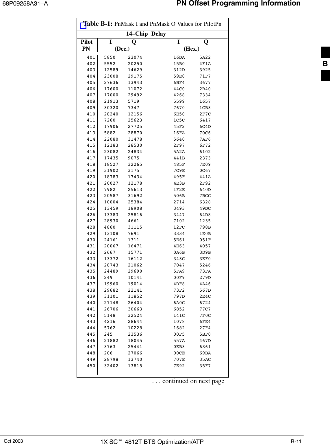
PN Offset Programming Information68P09258A31–AOct 2003 1X SCt 4812T BTS Optimization/ATP B-11Table B-1: PnMask I and PnMask Q Values for PilotPn14–Chip  Delay Pilot I Q I Q  PN (Dec.)          (Hex.)401 5850 23074 16DA 5A22402 5552 20250 15B0 4F1A403 12589 14629 312D 3925404 23008 29175 59E0 71F7405 27636 13943 6BF4 3677406 17600 11072 44C0 2B40407 17000 29492 4268 7334408 21913 5719 5599 1657409 30320 7347 7670 1CB3410 28240 12156 6E50 2F7C411 7260 25623 1C5C 6417412 17906 27725 45F2 6C4D413 5882 28870 16FA 70C6414 22080 31478 5640 7AF6415 12183 28530 2F97 6F72416 23082 24834 5A2A 6102417 17435 9075 441B 2373418 18527 32265 485F 7E09419 31902 3175 7C9E 0C67420 18783 17434 495F 441A421 20027 12178 4E3B 2F92422 7982 25613 1F2E 640D423 20587 31692 506B 7BCC424 10004 25384 2714 6328425 13459 18908 3493 49DC426 13383 25816 3447 64D8427 28930 4661 7102 1235428 4860 31115 12FC 798B429 13108 7691 3334 1E0B430 24161 1311 5E61 051F431 20067 16471 4E63 4057432 2667 15771 0A6B 3D9B433 13372 16112 343C 3EF0434 28743 21062 7047 5246435 24489 29690 5FA9 73FA436 249 10141 00F9 279D437 19960 19014 4DF8 4A46438 29682 22141 73F2 567D439 31101 11852 797D 2E4C440 27148 26404 6A0C 6724441 26706 30663 6852 77C7442 5148 32524 141C 7F0C443 4216 28644 1078 6FE4444 5762 10228 1682 27F4445 245 23536 00F5 5BF0446 21882 18045 557A 467D447 3763 25441 0EB3 6361448 206 27066 00CE 69BA449 28798 13740 707E 35AC450 32402 13815 7E92 35F7. . . continued on next pageB
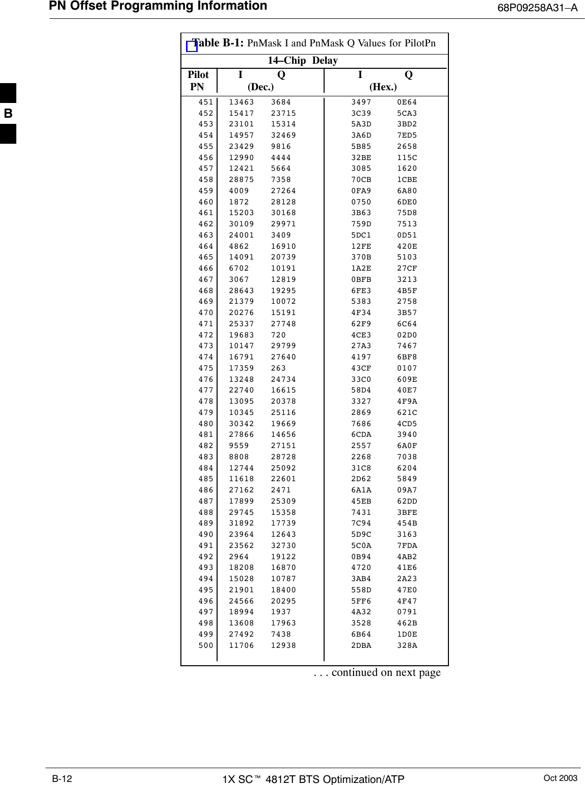
PN Offset Programming Information 68P09258A31–AOct 20031X SCt 4812T BTS Optimization/ATPB-12Table B-1: PnMask I and PnMask Q Values for PilotPn14–Chip  Delay Pilot I Q I Q  PN (Dec.)          (Hex.)451 13463 3684 3497 0E64452 15417 23715 3C39 5CA3453 23101 15314 5A3D 3BD2454 14957 32469 3A6D 7ED5455 23429 9816 5B85 2658456 12990 4444 32BE 115C457 12421 5664 3085 1620458 28875 7358 70CB 1CBE459 4009 27264 0FA9 6A80460 1872 28128 0750 6DE0461 15203 30168 3B63 75D8462 30109 29971 759D 7513463 24001 3409 5DC1 0D51464 4862 16910 12FE 420E465 14091 20739 370B 5103466 6702 10191 1A2E 27CF467 3067 12819 0BFB 3213468 28643 19295 6FE3 4B5F469 21379 10072 5383 2758470 20276 15191 4F34 3B57471 25337 27748 62F9 6C64472 19683 720 4CE3 02D0473 10147 29799 27A3 7467474 16791 27640 4197 6BF8475 17359 263 43CF 0107476 13248 24734 33C0 609E477 22740 16615 58D4 40E7478 13095 20378 3327 4F9A479 10345 25116 2869 621C480 30342 19669 7686 4CD5481 27866 14656 6CDA 3940482 9559 27151 2557 6A0F483 8808 28728 2268 7038484 12744 25092 31C8 6204485 11618 22601 2D62 5849486 27162 2471 6A1A 09A7487 17899 25309 45EB 62DD488 29745 15358 7431 3BFE489 31892 17739 7C94 454B490 23964 12643 5D9C 3163491 23562 32730 5C0A 7FDA492 2964 19122 0B94 4AB2493 18208 16870 4720 41E6494 15028 10787 3AB4 2A23495 21901 18400 558D 47E0496 24566 20295 5FF6 4F47497 18994 1937 4A32 0791498 13608 17963 3528 462B499 27492 7438 6B64 1D0E500 11706 12938 2DBA 328A. . . continued on next pageB
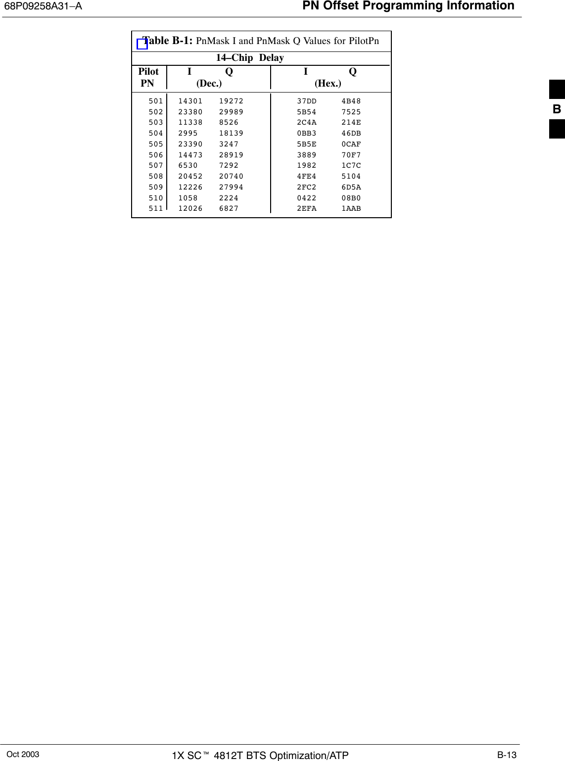
PN Offset Programming Information68P09258A31–AOct 2003 1X SCt 4812T BTS Optimization/ATP B-13Table B-1: PnMask I and PnMask Q Values for PilotPn14–Chip  Delay Pilot I Q I Q  PN (Dec.)          (Hex.)501 14301 19272 37DD 4B48502 23380 29989 5B54 7525503 11338 8526 2C4A 214E504 2995 18139 0BB3 46DB505 23390 3247 5B5E 0CAF506 14473 28919 3889 70F7507 6530 7292 1982 1C7C508 20452 20740 4FE4 5104509 12226 27994 2FC2 6D5A510 1058 2224 0422 08B0511 12026 6827 2EFA 1AAB B
PN Offset Programming Information 68P09258A31–AOct 20031X SCt 4812T BTS Optimization/ATPB-14NotesB
Oct 2003 1X SCt 4812T BTS Optimization/ATP C-1Appendix CFRU Optimization/ATP Test MatrixC
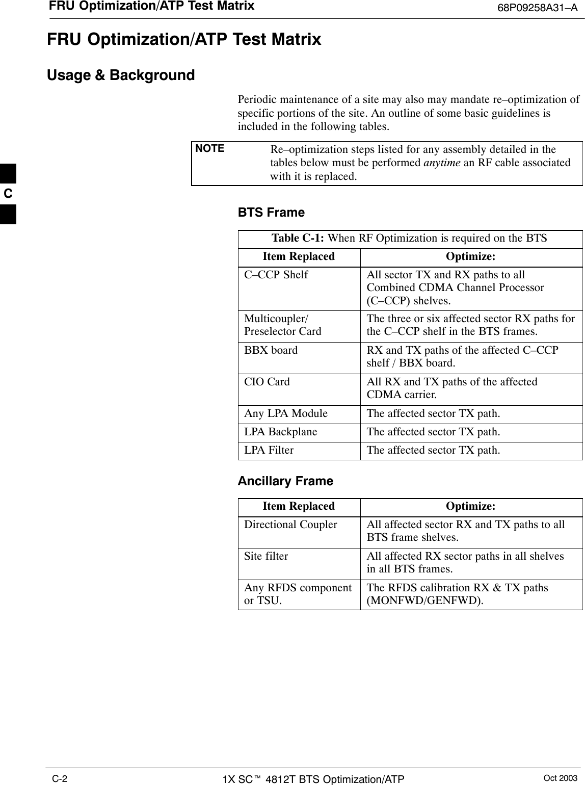
FRU Optimization/ATP Test Matrix 68P09258A31–AOct 20031X SCt 4812T BTS Optimization/ATPC-2FRU Optimization/ATP Test MatrixUsage & BackgroundPeriodic maintenance of a site may also may mandate re–optimization ofspecific portions of the site. An outline of some basic guidelines isincluded in the following tables.NOTE Re–optimization steps listed for any assembly detailed in thetables below must be performed anytime an RF cable associatedwith it is replaced.BTS FrameTable C-1: When RF Optimization is required on the BTSItem Replaced Optimize:C–CCP Shelf All sector TX and RX paths to allCombined CDMA Channel Processor(C–CCP) shelves.Multicoupler/Preselector CardThe three or six affected sector RX paths forthe C–CCP shelf in the BTS frames.BBX board RX and TX paths of the affected C–CCPshelf / BBX board.CIO Card All RX and TX paths of the affectedCDMA carrier.Any LPA Module The affected sector TX path.LPA Backplane The affected sector TX path.LPA Filter The affected sector TX path.Ancillary Frame Item Replaced Optimize:Directional Coupler All affected sector RX and TX paths to allBTS frame shelves.Site filter All affected RX sector paths in all shelvesin all BTS frames.Any RFDS componentor TSU.The RFDS calibration RX & TX paths(MONFWD/GENFWD).C
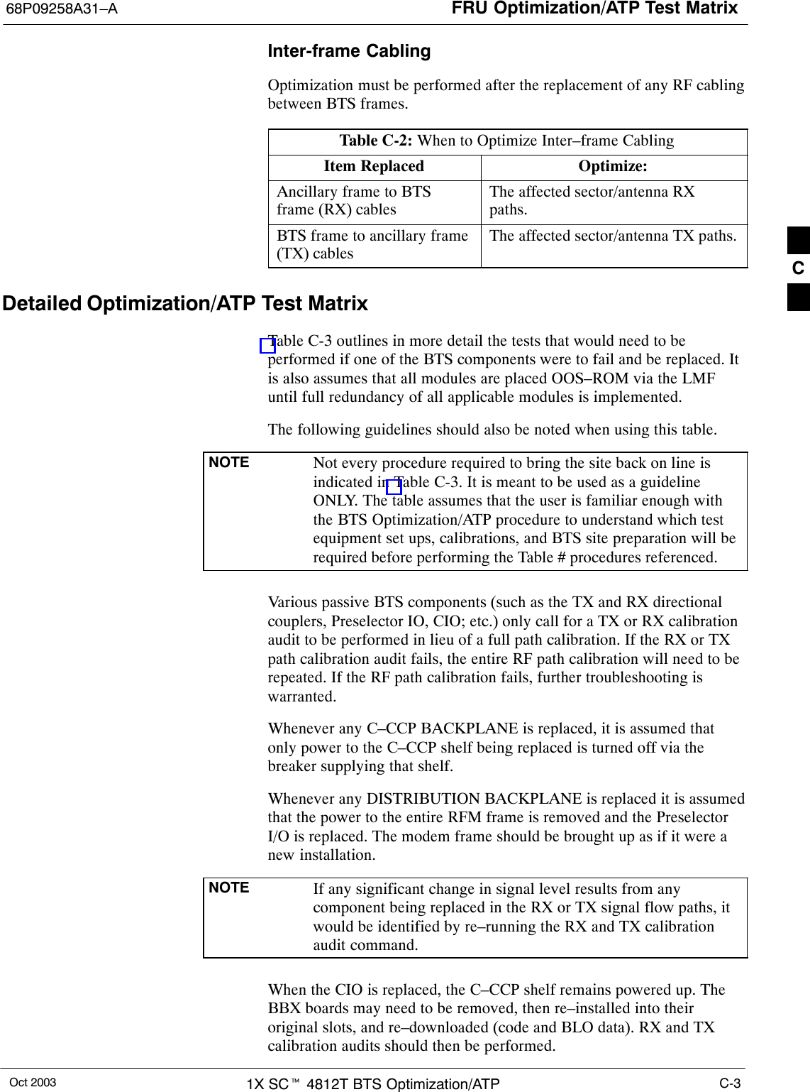
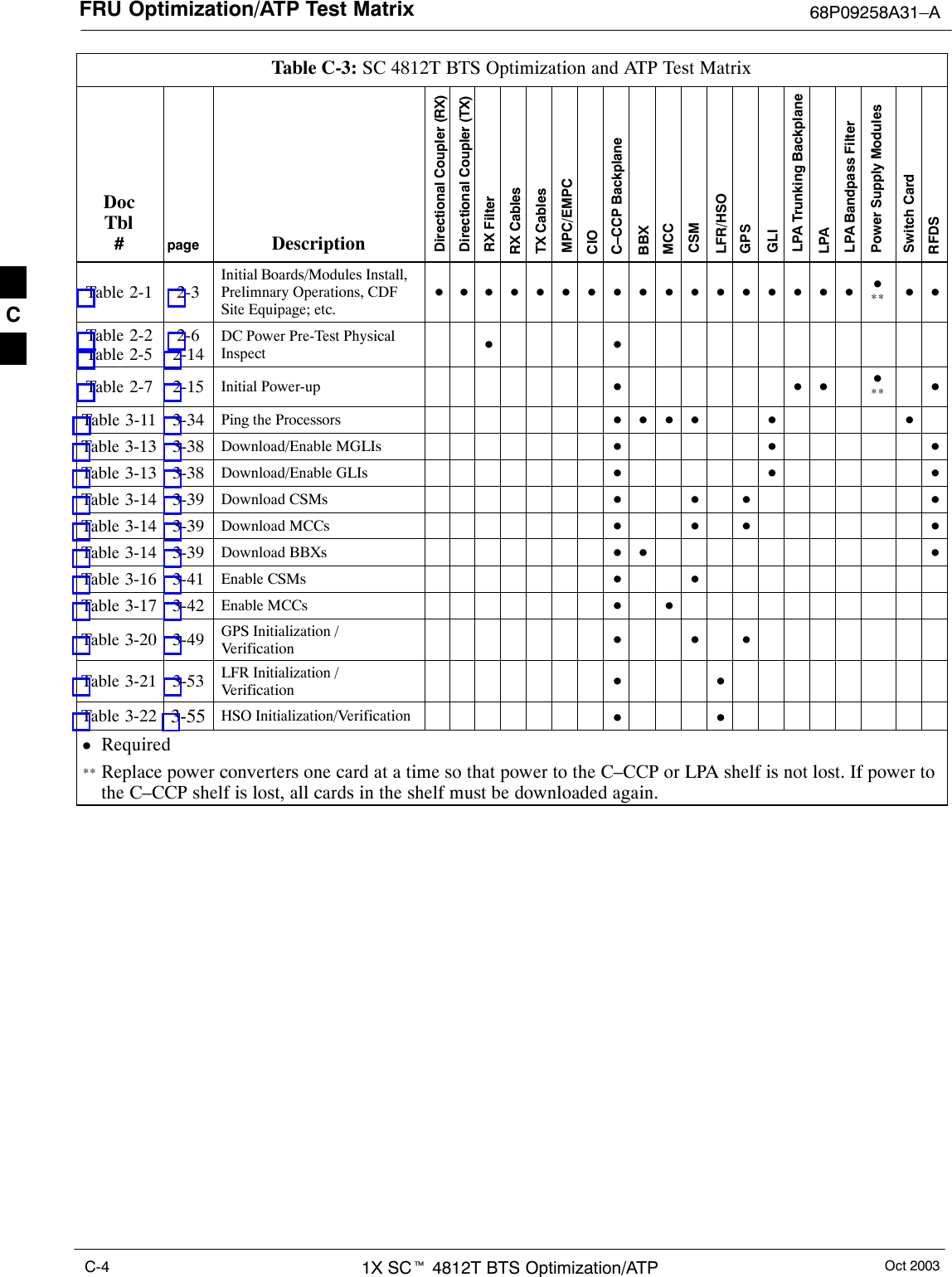
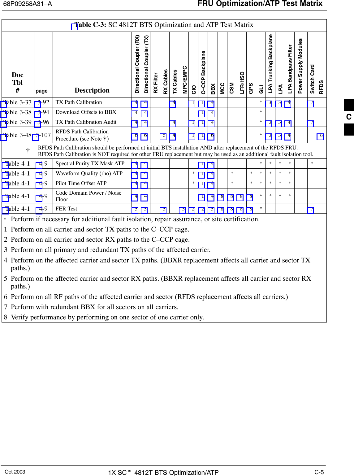
FRU Optimization/ATP Test Matrix68P09258A31–AOct 2003 1X SCt 4812T BTS Optimization/ATP C-3Inter-frame CablingOptimization must be performed after the replacement of any RF cablingbetween BTS frames.Table C-2: When to Optimize Inter–frame CablingItem Replaced Optimize:Ancillary frame to BTSframe (RX) cablesThe affected sector/antenna RXpaths.BTS frame to ancillary frame(TX) cablesThe affected sector/antenna TX paths.Detailed Optimization/ATP Test MatrixTable C-3 outlines in more detail the tests that would need to beperformed if one of the BTS components were to fail and be replaced. Itis also assumes that all modules are placed OOS–ROM via the LMFuntil full redundancy of all applicable modules is implemented.The following guidelines should also be noted when using this table.NOTE Not every procedure required to bring the site back on line isindicated in Table C-3. It is meant to be used as a guidelineONLY. The table assumes that the user is familiar enough withthe BTS Optimization/ATP procedure to understand which testequipment set ups, calibrations, and BTS site preparation will berequired before performing the Table # procedures referenced.Various passive BTS components (such as the TX and RX directionalcouplers, Preselector IO, CIO; etc.) only call for a TX or RX calibrationaudit to be performed in lieu of a full path calibration. If the RX or TXpath calibration audit fails, the entire RF path calibration will need to berepeated. If the RF path calibration fails, further troubleshooting iswarranted.Whenever any C–CCP BACKPLANE is replaced, it is assumed thatonly power to the C–CCP shelf being replaced is turned off via thebreaker supplying that shelf.Whenever any DISTRIBUTION BACKPLANE is replaced it is assumedthat the power to the entire RFM frame is removed and the PreselectorI/O is replaced. The modem frame should be brought up as if it were anew installation.NOTE If any significant change in signal level results from anycomponent being replaced in the RX or TX signal flow paths, itwould be identified by re–running the RX and TX calibrationaudit command.When the CIO is replaced, the C–CCP shelf remains powered up. TheBBX boards may need to be removed, then re–installed into theiroriginal slots, and re–downloaded (code and BLO data). RX and TXcalibration audits should then be performed.C
FRU Optimization/ATP Test Matrix 68P09258A31–AOct 20031X SCt 4812T BTS Optimization/ATPC-4Table C-3: SC 4812T BTS Optimization and ATP Test MatrixDocTbl#page DescriptionDirectional Coupler (RX)Directional Coupler (TX)RX FilterRX CablesTX CablesMPC/EMPCCIOC–CCP BackplaneBBXMCCCSMLFR/HSOGPSGLILPA Trunking BackplaneLPALPA Bandpass FilterPower Supply ModulesSwitch CardRFDSTable 2-1 2-3Initial Boards/Modules Install,Prelimnary Operations, CDFSite Equipage; etc.DDDDDDDDDDDDDDDDD D** D DTable 2-2Table 2-52-62-14DC Power Pre-Test PhysicalInspect D DTable 2-7 2-15 Initial Power-up D D D D** DTable 3-11 3-34 Ping the Processors D D D D D DTable 3-13 3-38 Download/Enable MGLIs D D DTable 3-13 3-38 Download/Enable GLIs D D DTable 3-14 3-39 Download CSMs D D D DTable 3-14 3-39 Download MCCs D D D DTable 3-14 3-39 Download BBXs D D DTable 3-16 3-41 Enable CSMs D DTable 3-17 3-42 Enable MCCs D DTable 3-20 3-49 GPS Initialization /Verification D D DTable 3-21 3-53 LFR Initialization /Verification D DTable 3-22 3-55 HSO Initialization/Verification D DDRequired** Replace power converters one card at a time so that power to the C–CCP or LPA shelf is not lost. If power tothe C–CCP shelf is lost, all cards in the shelf must be downloaded again.C
FRU Optimization/ATP Test Matrix68P09258A31–AOct 2003 1X SCt 4812T BTS Optimization/ATP C-5Table C-3: SC 4812T BTS Optimization and ATP Test MatrixDocTbl#RFDSSwitch CardPower Supply ModulesLPA Bandpass FilterLPALPA Trunking BackplaneGLIGPSLFR/HSOCSMMCCBBXC–CCP BackplaneCIOMPC/EMPCTX CablesRX CablesRX FilterDirectional Coupler (TX)Directional Coupler (RX)DescriptionpageTable 3-37 3-92 TX Path Calibration 4 4 4 1 1 4* 3 3 47Table 3-38 3-94 Download Offsets to BBX 4 4 1 4 *Table 3-39 3-96 TX Path Calibration Audit 44 4 1 1 4 * 3 3 4 7Table 3-48 3-107 RFDS Path CalibrationProcedure (see Note [)6 6 541 1 6* 3 3 46[RFDS Path Calibration should be performed at initial BTS installation AND after replacement of the RFDS FRU. RFDS Path Calibration is NOT required for other FRU replacement but may be used as an additional fault isolation tool.Table 4-1 4-9 Spectral Purity TX Mask ATP 4 4 14**** *Table 4-1 4-9 Waveform Quality (rho) ATP 4 4 * 1 4* *****Table 4-1 4-9 Pilot Time Offset ATP 4 4 * 1 4* *****Table 4-1 4-9 Code Domain Power / NoiseFloor 4 4 148888****Table 4-1 4-9 FER Test 5 5 5 5 2 2 5 8 8 8 8 * 7*Perform if necessary for additional fault isolation, repair assurance, or site certification.1 Perform on all carrier and sector TX paths to the C–CCP cage.2 Perform on all carrier and sector RX paths to the C–CCP cage.3 Perform on all primary and redundant TX paths of the affected carrier.4 Perform on the affected carrier and sector TX paths. (BBXR replacement affects all carrier and sector TXpaths.)5 Perform on the affected carrier and sector RX paths. (BBXR replacement affects all carrier and sector RXpaths.)6 Perform on all RF paths of the affected carrier and sector (RFDS replacement affects all carriers.)7 Perform with redundant BBX for all sectors on all carriers.8 Verify performance by performing on one sector of one carrier only.C
FRU Optimization/ATP Test Matrix 68P09258A31–AOct 20031X SCt 4812T BTS Optimization/ATPC-6NotesC
Oct 2003 1X SCt 4812T BTS Optimization/ATP D-1Appendix DBBX Gain Set Point vs. BTS OutputD
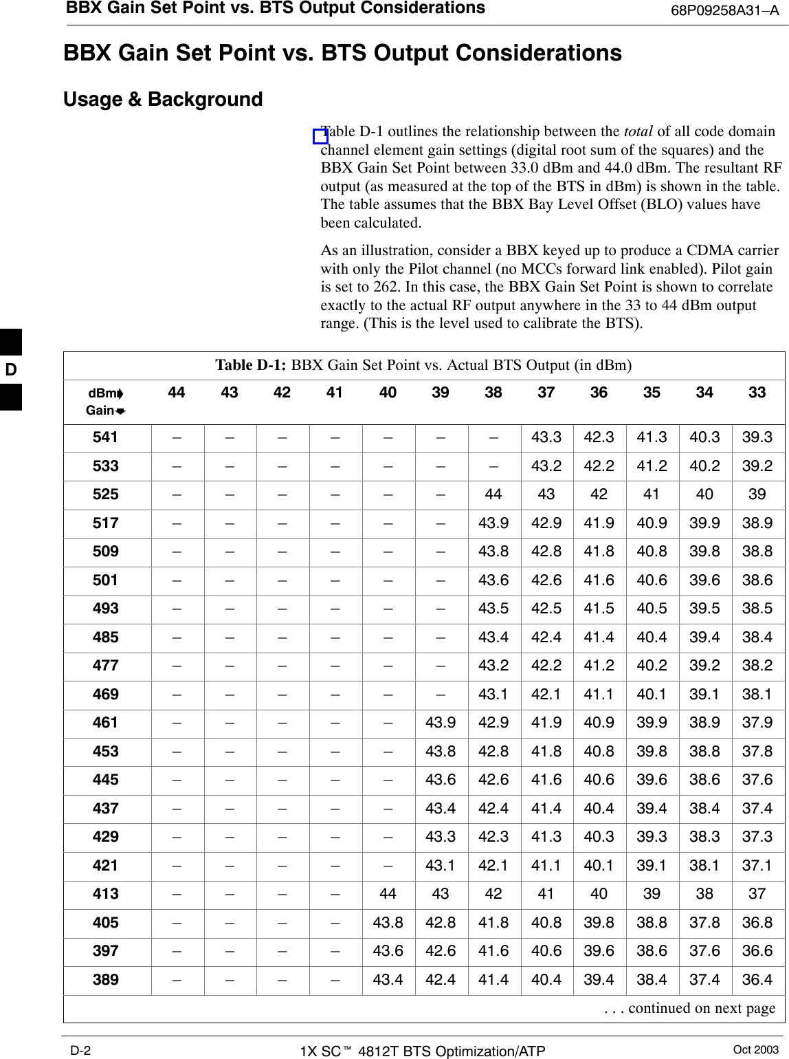
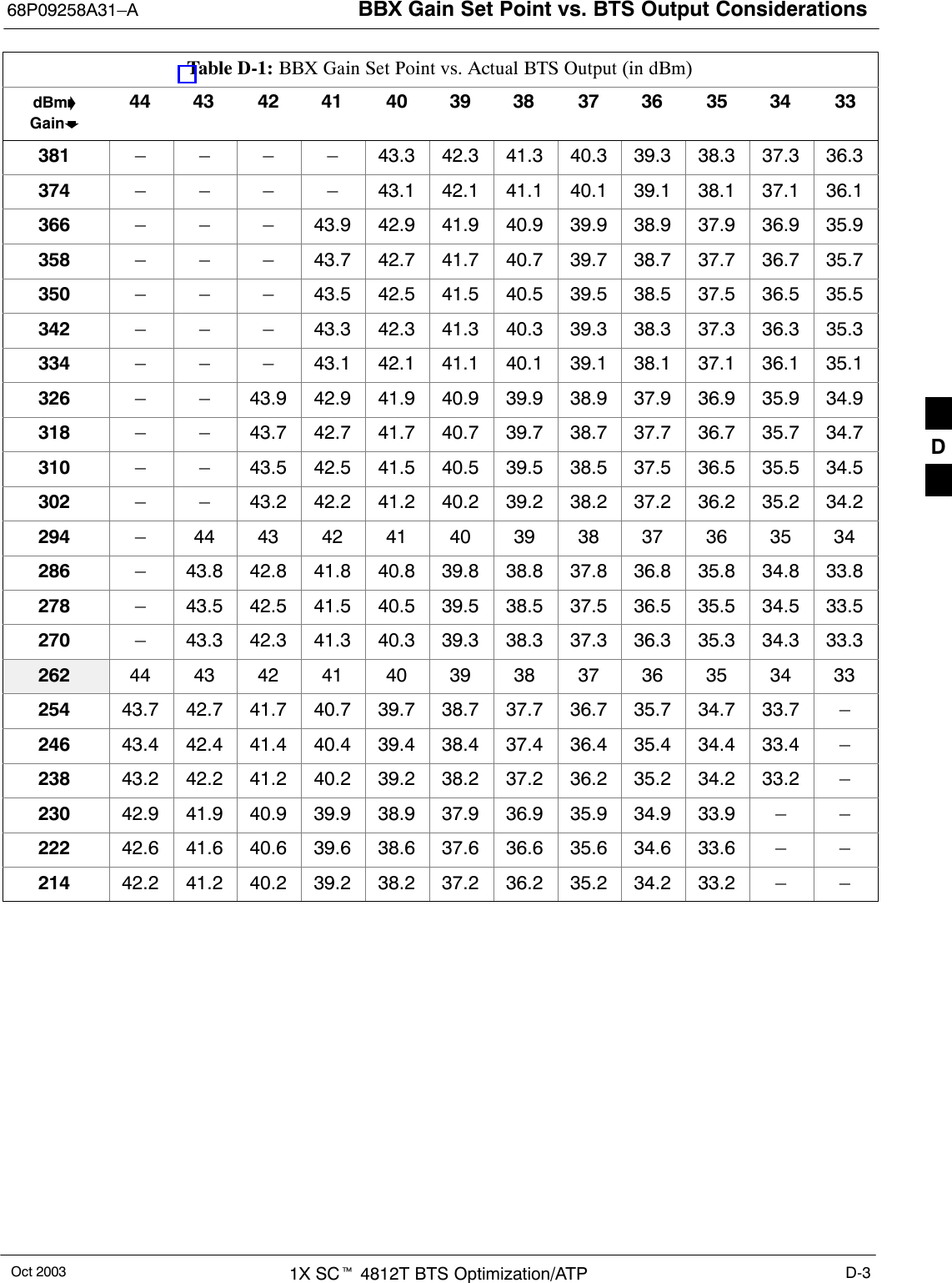
BBX Gain Set Point vs. BTS Output Considerations 68P09258A31–AOct 20031X SCt 4812T BTS Optimization/ATPD-2BBX Gain Set Point vs. BTS Output ConsiderationsUsage & BackgroundTable D-1 outlines the relationship between the total of all code domainchannel element gain settings (digital root sum of the squares) and theBBX Gain Set Point between 33.0 dBm and 44.0 dBm. The resultant RFoutput (as measured at the top of the BTS in dBm) is shown in the table.The table assumes that the BBX Bay Level Offset (BLO) values havebeen calculated.As an illustration, consider a BBX keyed up to produce a CDMA carrierwith only the Pilot channel (no MCCs forward link enabled). Pilot gainis set to 262. In this case, the BBX Gain Set Point is shown to correlateexactly to the actual RF output anywhere in the 33 to 44 dBm outputrange. (This is the level used to calibrate the BTS).Table D-1: BBX Gain Set Point vs. Actual BTS Output (in dBm)dBm’Gainb44 43 42 41 40 39 38 37 36 35 34 33541 – – – – – – – 43.3 42.3 41.3 40.3 39.3533 – – – – – – – 43.2 42.2 41.2 40.2 39.2525 – – – – – – 44 43 42 41 40 39517 – – – – – – 43.9 42.9 41.9 40.9 39.9 38.9509 – – – – – – 43.8 42.8 41.8 40.8 39.8 38.8501 – – – – – – 43.6 42.6 41.6 40.6 39.6 38.6493 – – – – – – 43.5 42.5 41.5 40.5 39.5 38.5485 – – – – – – 43.4 42.4 41.4 40.4 39.4 38.4477 – – – – – – 43.2 42.2 41.2 40.2 39.2 38.2469 – – – – – – 43.1 42.1 41.1 40.1 39.1 38.1461 – – – – – 43.9 42.9 41.9 40.9 39.9 38.9 37.9453 – – – – – 43.8 42.8 41.8 40.8 39.8 38.8 37.8445 – – – – – 43.6 42.6 41.6 40.6 39.6 38.6 37.6437 – – – – – 43.4 42.4 41.4 40.4 39.4 38.4 37.4429 – – – – – 43.3 42.3 41.3 40.3 39.3 38.3 37.3421 – – – – – 43.1 42.1 41.1 40.1 39.1 38.1 37.1413 – – – – 44 43 42 41 40 39 38 37405 – – – – 43.8 42.8 41.8 40.8 39.8 38.8 37.8 36.8397 – – – – 43.6 42.6 41.6 40.6 39.6 38.6 37.6 36.6389 – – – – 43.4 42.4 41.4 40.4 39.4 38.4 37.4 36.4 . . . continued on next pageD
BBX Gain Set Point vs. BTS Output Considerations68P09258A31–AOct 2003 1X SCt 4812T BTS Optimization/ATP D-3Table D-1: BBX Gain Set Point vs. Actual BTS Output (in dBm)dBm’Gainb333435363738394041424344381 – – – – 43.3 42.3 41.3 40.3 39.3 38.3 37.3 36.3374 – – – – 43.1 42.1 41.1 40.1 39.1 38.1 37.1 36.1366 – – – 43.9 42.9 41.9 40.9 39.9 38.9 37.9 36.9 35.9358 – – – 43.7 42.7 41.7 40.7 39.7 38.7 37.7 36.7 35.7350 – – – 43.5 42.5 41.5 40.5 39.5 38.5 37.5 36.5 35.5342 – – – 43.3 42.3 41.3 40.3 39.3 38.3 37.3 36.3 35.3334 – – – 43.1 42.1 41.1 40.1 39.1 38.1 37.1 36.1 35.1326 – – 43.9 42.9 41.9 40.9 39.9 38.9 37.9 36.9 35.9 34.9318 – – 43.7 42.7 41.7 40.7 39.7 38.7 37.7 36.7 35.7 34.7310 – – 43.5 42.5 41.5 40.5 39.5 38.5 37.5 36.5 35.5 34.5302 – – 43.2 42.2 41.2 40.2 39.2 38.2 37.2 36.2 35.2 34.2294 – 44 43 42 41 40 39 38 37 36 35 34286 – 43.8 42.8 41.8 40.8 39.8 38.8 37.8 36.8 35.8 34.8 33.8278 – 43.5 42.5 41.5 40.5 39.5 38.5 37.5 36.5 35.5 34.5 33.5270 – 43.3 42.3 41.3 40.3 39.3 38.3 37.3 36.3 35.3 34.3 33.3262 44 43 42 41 40 39 38 37 36 35 34 33254 43.7 42.7 41.7 40.7 39.7 38.7 37.7 36.7 35.7 34.7 33.7 –246 43.4 42.4 41.4 40.4 39.4 38.4 37.4 36.4 35.4 34.4 33.4 –238 43.2 42.2 41.2 40.2 39.2 38.2 37.2 36.2 35.2 34.2 33.2 –230 42.9 41.9 40.9 39.9 38.9 37.9 36.9 35.9 34.9 33.9 – –222 42.6 41.6 40.6 39.6 38.6 37.6 36.6 35.6 34.6 33.6 – –214 42.2 41.2 40.2 39.2 38.2 37.2 36.2 35.2 34.2 33.2 – –D
BBX Gain Set Point vs. BTS Output Considerations 68P09258A31–AOct 20031X SCt 4812T BTS Optimization/ATPD-4NotesD
Oct 2003 1X SCt 4812T BTS Optimization/ATP E-1Appendix ECDMA Operating FrequencyE
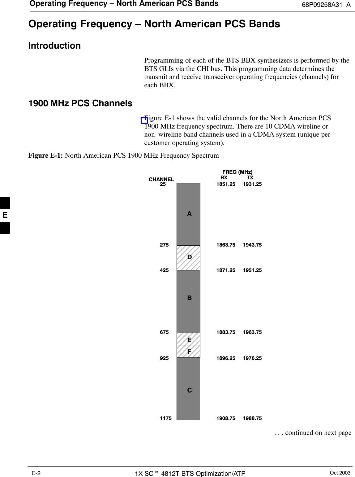
Operating Frequency – North American PCS Bands 68P09258A31–AOct 20031X SCt 4812T BTS Optimization/ATPE-2Operating Frequency – North American PCS BandsIntroductionProgramming of each of the BTS BBX synthesizers is performed by theBTS GLIs via the CHI bus. This programming data determines thetransmit and receive transceiver operating frequencies (channels) foreach BBX.1900 MHz PCS ChannelsFigure E-1 shows the valid channels for the North American PCS1900 MHz frequency spectrum. There are 10 CDMA wireline ornon–wireline band channels used in a CDMA system (unique percustomer operating system).Figure E-1: North American PCS 1900 MHz Frequency Spectrum  FREQ  (MHz)RX              TX2751175CHANNEL1863.759251851.25251871.25425675 1883.751896.251908.751943.751931.251951.251963.751976.251988.75ADBEFC . . . continued on next pageE
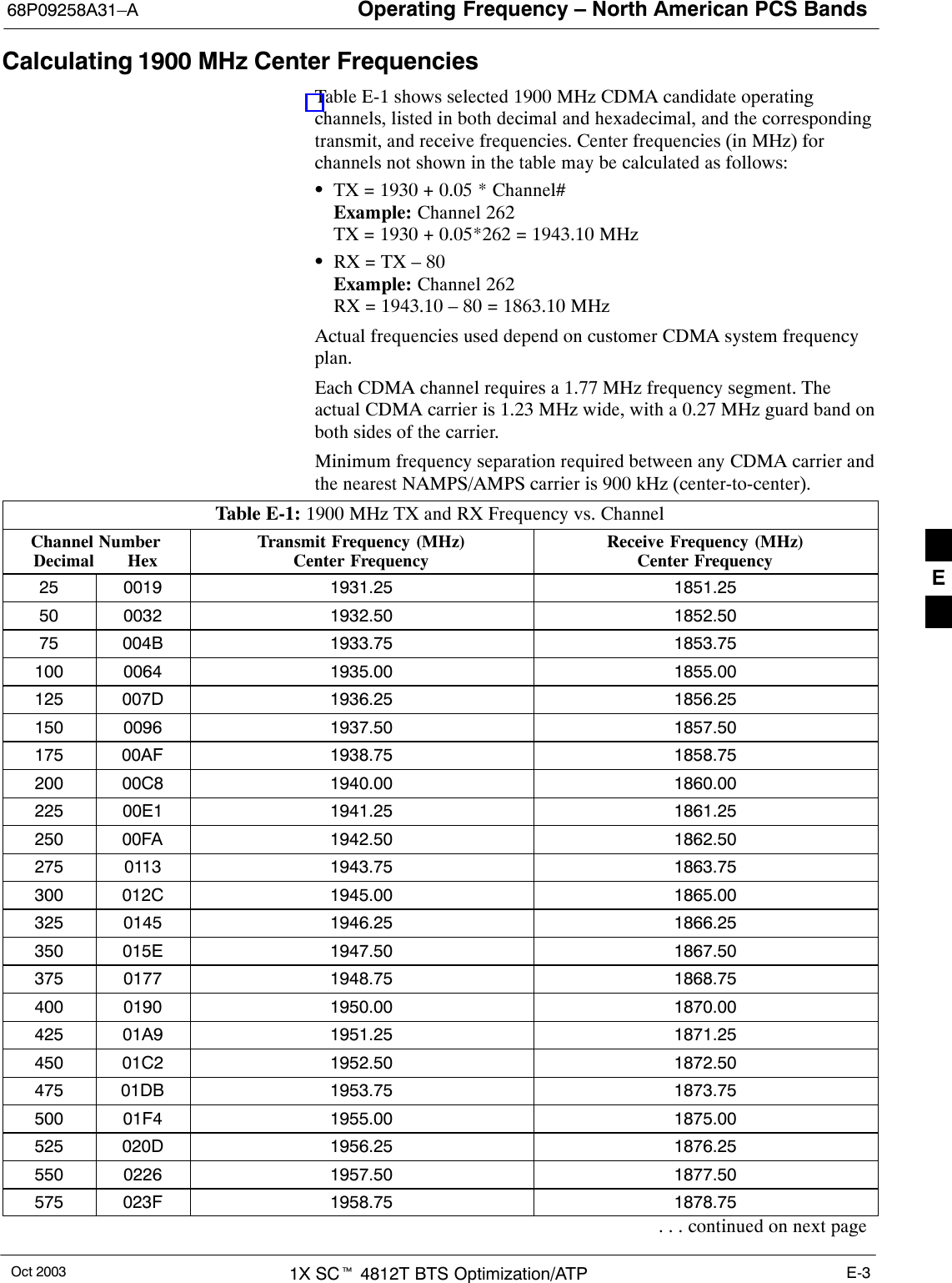
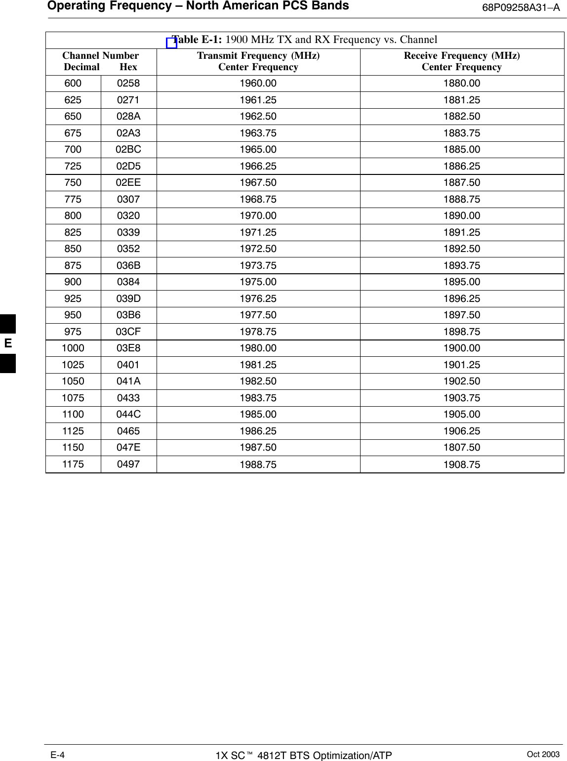
Operating Frequency – North American PCS Bands68P09258A31–AOct 2003 1X SCt 4812T BTS Optimization/ATP E-3Calculating 1900 MHz Center FrequenciesTable E-1 shows selected 1900 MHz CDMA candidate operatingchannels, listed in both decimal and hexadecimal, and the correspondingtransmit, and receive frequencies. Center frequencies (in MHz) forchannels not shown in the table may be calculated as follows:STX = 1930 + 0.05 * Channel#Example: Channel 262TX = 1930 + 0.05*262 = 1943.10 MHzSRX = TX – 80Example: Channel 262RX = 1943.10 – 80 = 1863.10 MHzActual frequencies used depend on customer CDMA system frequencyplan.Each CDMA channel requires a 1.77 MHz frequency segment. Theactual CDMA carrier is 1.23 MHz wide, with a 0.27 MHz guard band onboth sides of the carrier.Minimum frequency separation required between any CDMA carrier andthe nearest NAMPS/AMPS carrier is 900 kHz (center-to-center).Table E-1: 1900 MHz TX and RX Frequency vs. ChannelChannel NumberDecimal       HexTransmit Frequency (MHz)Center FrequencyReceive Frequency (MHz)Center Frequency25 0019 1931.25 1851.2550 0032 1932.50 1852.5075 004B 1933.75 1853.75100 0064 1935.00 1855.00125 007D 1936.25 1856.25150 0096 1937.50 1857.50175 00AF 1938.75 1858.75200 00C8 1940.00 1860.00225 00E1 1941.25 1861.25250 00FA 1942.50 1862.50275 0113 1943.75 1863.75300 012C 1945.00 1865.00325 0145 1946.25 1866.25350 015E 1947.50 1867.50375 0177 1948.75 1868.75400 0190 1950.00 1870.00425 01A9 1951.25 1871.25450 01C2 1952.50 1872.50475 01DB 1953.75 1873.75500 01F4 1955.00 1875.00525 020D 1956.25 1876.25550 0226 1957.50 1877.50575 023F 1958.75 1878.75. . . continued on next pageE
Operating Frequency – North American PCS Bands 68P09258A31–AOct 20031X SCt 4812T BTS Optimization/ATPE-4Table E-1: 1900 MHz TX and RX Frequency vs. ChannelChannel NumberDecimal       HexReceive Frequency (MHz)Center FrequencyTransmit Frequency (MHz)Center Frequency600 0258 1960.00 1880.00625 0271 1961.25 1881.25650 028A 1962.50 1882.50675 02A3 1963.75 1883.75700 02BC 1965.00 1885.00725 02D5 1966.25 1886.25750 02EE 1967.50 1887.50775 0307 1968.75 1888.75800 0320 1970.00 1890.00825 0339 1971.25 1891.25850 0352 1972.50 1892.50875 036B 1973.75 1893.75900 0384 1975.00 1895.00925 039D 1976.25 1896.25950 03B6 1977.50 1897.50975 03CF 1978.75 1898.751000 03E8 1980.00 1900.001025 0401 1981.25 1901.251050 041A 1982.50 1902.501075 0433 1983.75 1903.751100 044C 1985.00 1905.001125 0465 1986.25 1906.251150 047E 1987.50 1807.501175 0497 1988.75 1908.75 E
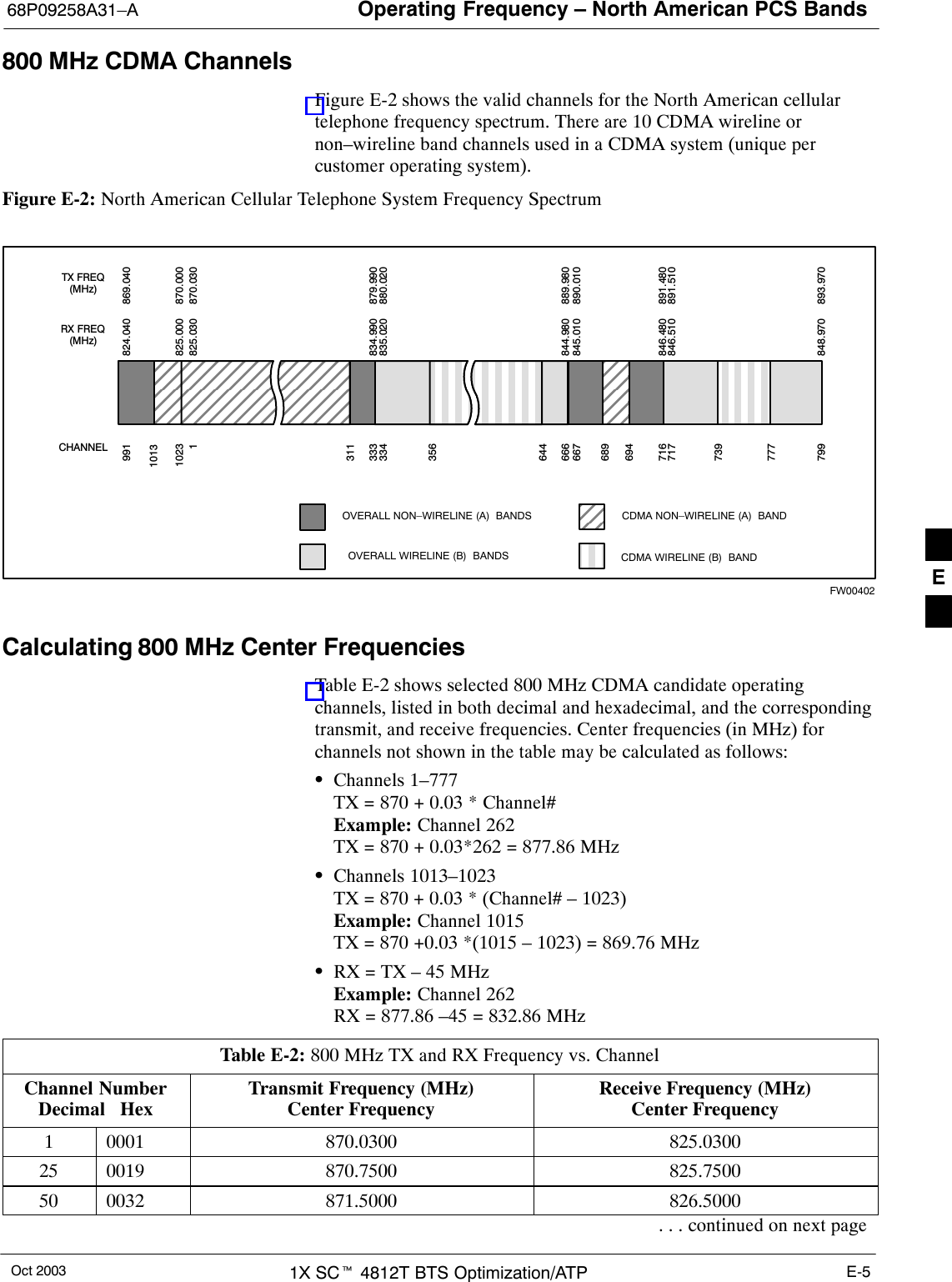
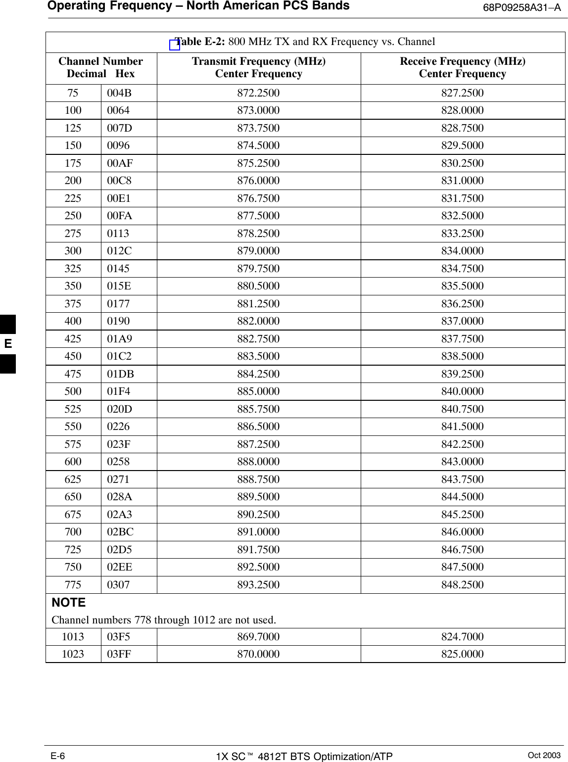
Operating Frequency – North American PCS Bands68P09258A31–AOct 2003 1X SCt 4812T BTS Optimization/ATP E-5800 MHz CDMA ChannelsFigure E-2 shows the valid channels for the North American cellulartelephone frequency spectrum. There are 10 CDMA wireline ornon–wireline band channels used in a CDMA system (unique percustomer operating system).Figure E-2: North American Cellular Telephone System Frequency SpectrumRX  FREQ(MHz)99110231333334666667716717799CHANNELOVERALL NON–WIRELINE (A)  BANDSOVERALL WIRELINE (B)  BANDS824.040825.000825.030834.990835.020844.980845.010846.480846.510848.970869.040870.000870.030879.990880.020889.980890.010891.480891.510893.970TX  FREQ(MHz)1013694689311356644739777CDMA NON–WIRELINE (A)  BANDCDMA WIRELINE (B)  BANDFW00402Calculating 800 MHz Center FrequenciesTable E-2 shows selected 800 MHz CDMA candidate operatingchannels, listed in both decimal and hexadecimal, and the correspondingtransmit, and receive frequencies. Center frequencies (in MHz) forchannels not shown in the table may be calculated as follows:SChannels 1–777TX = 870 + 0.03 * Channel#Example: Channel 262TX = 870 + 0.03*262 = 877.86 MHzSChannels 1013–1023TX = 870 + 0.03 * (Channel# – 1023)Example: Channel 1015TX = 870 +0.03 *(1015 – 1023) = 869.76 MHzSRX = TX – 45 MHzExample: Channel 262RX = 877.86 –45 = 832.86 MHzTable E-2: 800 MHz TX and RX Frequency vs. ChannelChannel NumberDecimal   HexTransmit Frequency (MHz)Center FrequencyReceive Frequency (MHz)Center Frequency1 0001 870.0300 825.030025 0019 870.7500 825.750050 0032 871.5000 826.5000. . . continued on next pageE
Operating Frequency – North American PCS Bands 68P09258A31–AOct 20031X SCt 4812T BTS Optimization/ATPE-6Table E-2: 800 MHz TX and RX Frequency vs. ChannelChannel NumberDecimal   HexReceive Frequency (MHz)Center FrequencyTransmit Frequency (MHz)Center Frequency75 004B 872.2500 827.2500100 0064 873.0000 828.0000125 007D 873.7500 828.7500150 0096 874.5000 829.5000175 00AF 875.2500 830.2500200 00C8 876.0000 831.0000225 00E1 876.7500 831.7500250 00FA 877.5000 832.5000275 0113 878.2500 833.2500300 012C 879.0000 834.0000325 0145 879.7500 834.7500350 015E 880.5000 835.5000375 0177 881.2500 836.2500400 0190 882.0000 837.0000425 01A9 882.7500 837.7500450 01C2 883.5000 838.5000475 01DB 884.2500 839.2500500 01F4 885.0000 840.0000525 020D 885.7500 840.7500550 0226 886.5000 841.5000575 023F 887.2500 842.2500600 0258 888.0000 843.0000625 0271 888.7500 843.7500650 028A 889.5000 844.5000675 02A3 890.2500 845.2500700 02BC 891.0000 846.0000725 02D5 891.7500 846.7500750 02EE 892.5000 847.5000775 0307 893.2500 848.2500NOTEChannel numbers 778 through 1012 are not used.1013 03F5 869.7000 824.70001023 03FF 870.0000 825.0000 E
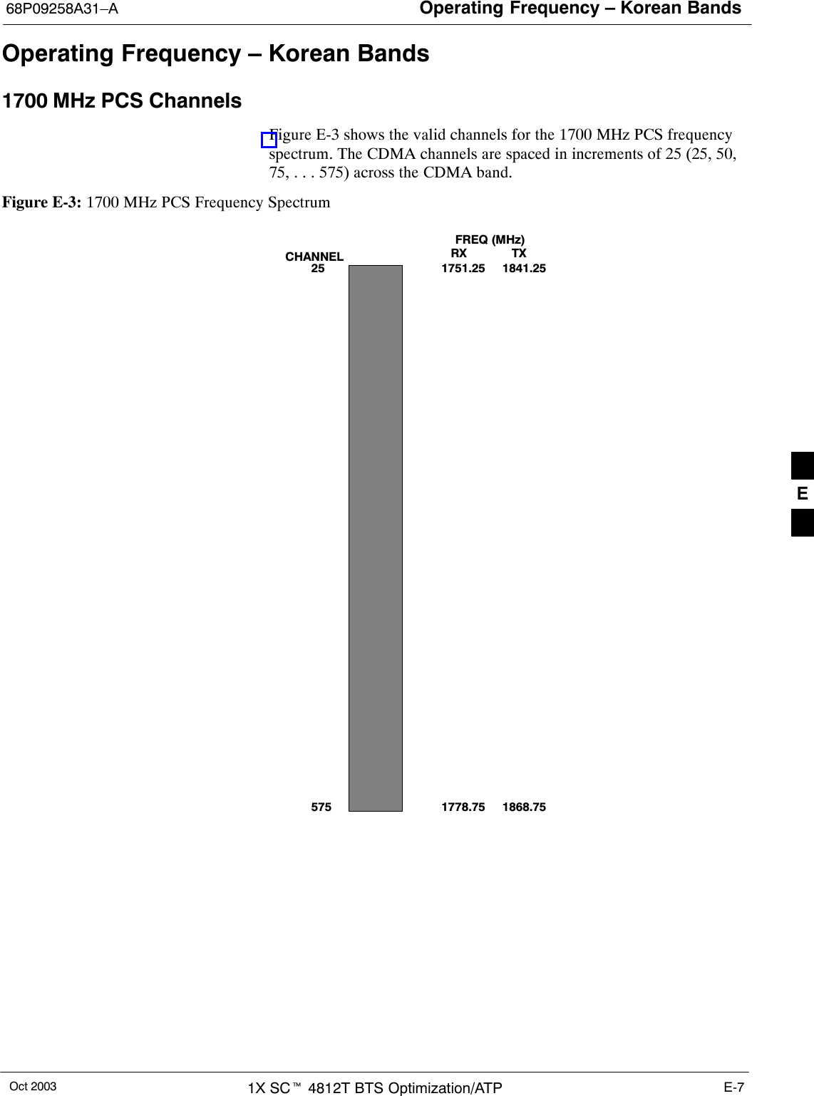
Operating Frequency – Korean Bands68P09258A31–AOct 2003 1X SCt 4812T BTS Optimization/ATP E-7Operating Frequency – Korean Bands1700 MHz PCS ChannelsFigure E-3 shows the valid channels for the 1700 MHz PCS frequencyspectrum. The CDMA channels are spaced in increments of 25 (25, 50,75, . . . 575) across the CDMA band.Figure E-3: 1700 MHz PCS Frequency Spectrum  FREQ  (MHz)RX              TX575CHANNEL 1751.25251778.751841.251868.75E
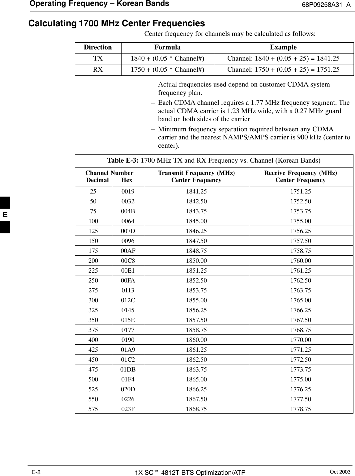
Operating Frequency – Korean Bands 68P09258A31–AOct 20031X SCt 4812T BTS Optimization/ATPE-8Calculating 1700 MHz Center FrequenciesCenter frequency for channels may be calculated as follows:Direction Formula ExampleTX 1840 + (0.05 * Channel#) Channel: 1840 + (0.05 + 25) = 1841.25RX 1750 + (0.05 * Channel#) Channel: 1750 + (0.05 + 25) = 1751.25– Actual frequencies used depend on customer CDMA systemfrequency plan.– Each CDMA channel requires a 1.77 MHz frequency segment. Theactual CDMA carrier is 1.23 MHz wide, with a 0.27 MHz guardband on both sides of the carrier– Minimum frequency separation required between any CDMAcarrier and the nearest NAMPS/AMPS carrier is 900 kHz (center tocenter).Table E-3: 1700 MHz TX and RX Frequency vs. Channel (Korean Bands)Channel NumberDecimal       HexTransmit Frequency (MHz)Center FrequencyReceive Frequency (MHz)Center Frequency25 0019 1841.25 1751.2550 0032 1842.50 1752.5075 004B 1843.75 1753.75100 0064 1845.00 1755.00125 007D 1846.25 1756.25150 0096 1847.50 1757.50175 00AF 1848.75 1758.75200 00C8 1850.00 1760.00225 00E1 1851.25 1761.25250 00FA 1852.50 1762.50275 0113 1853.75 1763.75300 012C 1855.00 1765.00325 0145 1856.25 1766.25350 015E 1857.50 1767.50375 0177 1858.75 1768.75400 0190 1860.00 1770.00425 01A9 1861.25 1771.25450 01C2 1862.50 1772.50475 01DB 1863.75 1773.75500 01F4 1865.00 1775.00525 020D 1866.25 1776.25550 0226 1867.50 1777.50575 023F 1868.75 1778.75E
Oct 2003 1X SCt 4812T BTS Optimization/ATP F-1Appendix FTest Equipment PreparationF
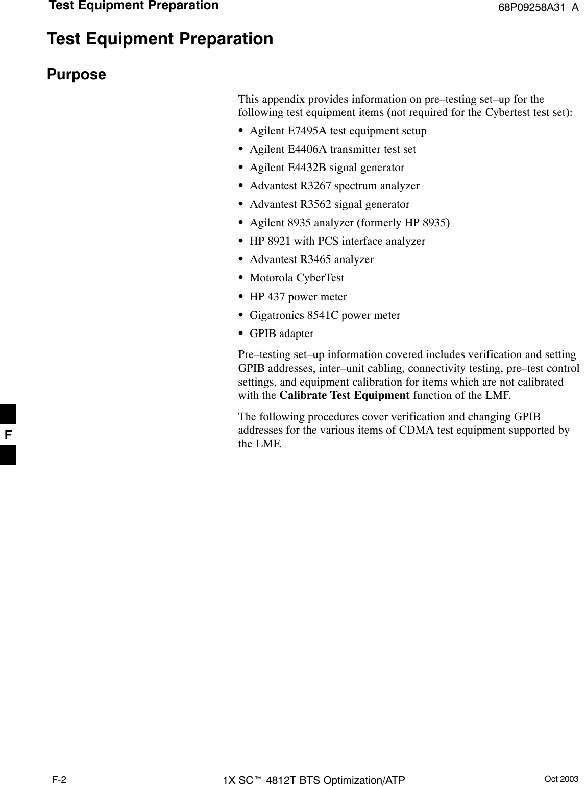
Test Equipment Preparation 68P09258A31–AOct 20031X SCt 4812T BTS Optimization/ATPF-2Test Equipment PreparationPurposeThis appendix provides information on pre–testing set–up for thefollowing test equipment items (not required for the Cybertest test set):SAgilent E7495A test equipment setupSAgilent E4406A transmitter test setSAgilent E4432B signal generatorSAdvantest R3267 spectrum analyzerSAdvantest R3562 signal generatorSAgilent 8935 analyzer (formerly HP 8935)SHP 8921 with PCS interface analyzerSAdvantest R3465 analyzerSMotorola CyberTestSHP 437 power meterSGigatronics 8541C power meterSGPIB adapterPre–testing set–up information covered includes verification and settingGPIB addresses, inter–unit cabling, connectivity testing, pre–test controlsettings, and equipment calibration for items which are not calibratedwith the Calibrate Test Equipment function of the LMF.The following procedures cover verification and changing GPIBaddresses for the various items of CDMA test equipment supported bythe LMF.F
Test Equipment Preparation68P09258A31–AOct 2003 1X SCt 4812T BTS Optimization/ATP F-3Agilent R7495A Test Equipment SetupThis test equipment requires a warm-up period of at least 30 minutesbefore BTS testing or calibration begins.Using the Agilent E7495A with the LMFThe Agilent E7495A does not require the use of the 19MHz frequencyreference; if connected, it will be ignored. The Even Sec SYNCconnection is required.The Agilent E7495A signal generator is only calibrated down to –80db.In order to achieve accurate FER testing, be sure the RX setup includesat least 40db of attenuation. This will ensure the signal generator willoutput sufficient power to operate in the calibrated range.Set the IP Address as described in Table F-1.Table F-1: Set IP Address on Agilent E7495A test setnStep Action1Use the System Button > Controls >IPAdmin to set anIP address on the E7495A as 128.0.0.49, and Netmask to255.255.255.128. ConnectionsIt is recommended that you use a hub with BNC and RJ–45 connections.[Suggested models: Netgear model EN104 (4 port) or EN108 (8 port).Do NOT use model numbers ending with “TP”; those have no BNCconnectors.]The LMF will connect to the hub which in turn is connected to the BTSand to the Agilent E7495A.Agilent E7495A to Hub – This is an Ethernet cable, RJ–45 to RJ–45.LMF to Hub – Use one of the following cables to connect the LMF tothe Hub:– Ethernet cable, RJ–45 to RJ–45 (be sure that the LAN card is set foreither AUTO or to use the RJ–45 only).– Coax cable between LAN card and Hub.  (Use a “T” on the hub andconnect a cable between the other end of the “T” and the BTS LANconnection).Hub to BTS – Use BNC “T” connector on the hub. [If your hub doesn’thave BNC ports, use a BNC to UTP adapter.]F
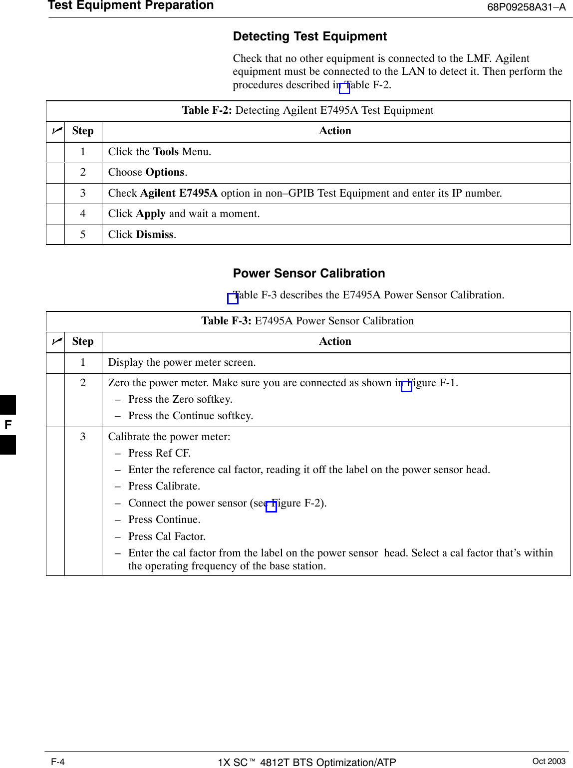
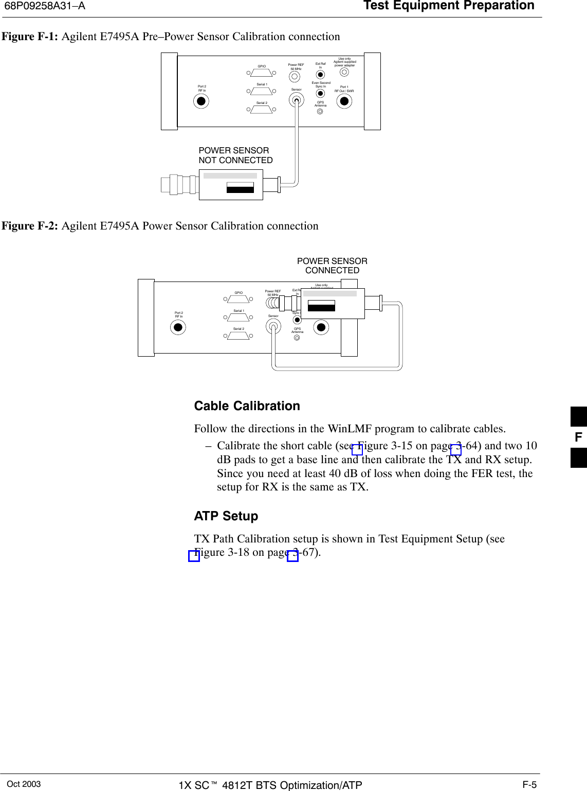
Test Equipment Preparation 68P09258A31–AOct 20031X SCt 4812T BTS Optimization/ATPF-4Detecting Test EquipmentCheck that no other equipment is connected to the LMF. Agilentequipment must be connected to the LAN to detect it. Then perform theprocedures described in Table F-2.Table F-2: Detecting Agilent E7495A Test EquipmentnStep Action1Click the Tools Menu.2 Choose Options.3 Check Agilent E7495A option in non–GPIB Test Equipment and enter its IP number.4 Click Apply and wait a moment.5 Click Dismiss. Power Sensor CalibrationTable F-3 describes the E7495A Power Sensor Calibration.Table F-3: E7495A Power Sensor CalibrationnStep Action1Display the power meter screen.2Zero the power meter. Make sure you are connected as shown in Figure F-1.– Press the Zero softkey.– Press the Continue softkey.3Calibrate the power meter:– Press Ref CF.– Enter the reference cal factor, reading it off the label on the power sensor head.– Press Calibrate.– Connect the power sensor (see Figure F-2).– Press Continue.– Press Cal Factor.– Enter the cal factor from the label on the power sensor  head. Select a cal factor that’s withinthe operating frequency of the base station. F
Test Equipment Preparation68P09258A31–AOct 2003 1X SCt 4812T BTS Optimization/ATP F-5Figure F-1: Agilent E7495A Pre–Power Sensor Calibration connectionUse onlyAgilent suppliedpower adapterGPSGPIOSerial 1Serial 2Power REF50 MHzSensorExt RefInEven SecondSync InAntennaPort 1RF Out / SWRPort 2RF InPOWER SENSORNOT CONNECTEDFigure F-2: Agilent E7495A Power Sensor Calibration connectionUse onlyAgilent suppliedpower adapterGPSGPIOSerial 1Serial 2Power REF50 MHzSensorExt RefInEven SecondSync InAntennaPort 1RF Out / SWRPort 2RF InPOWER SENSORCONNECTEDCable CalibrationFollow the directions in the WinLMF program to calibrate cables.– Calibrate the short cable (see Figure 3-15 on page 3-64) and two 10dB pads to get a base line and then calibrate the TX and RX setup.Since you need at least 40 dB of loss when doing the FER test, thesetup for RX is the same as TX.ATP SetupTX Path Calibration setup is shown in Test Equipment Setup (seeFigure 3-18 on page 3-67).F
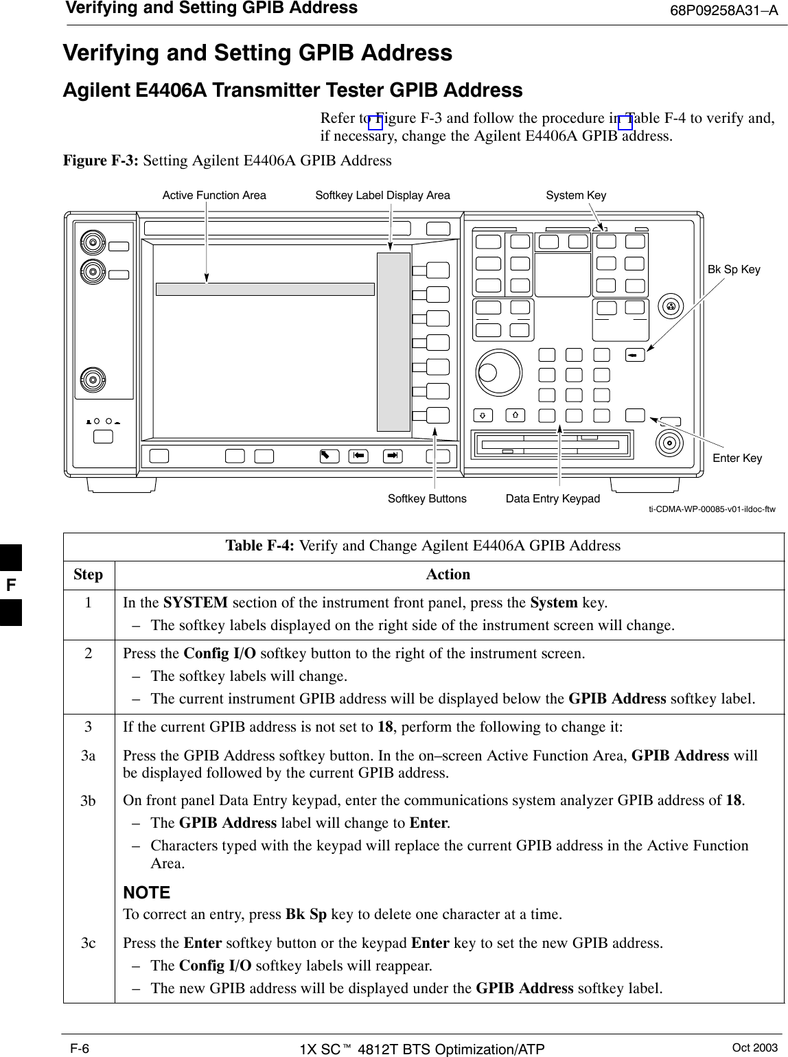
Verifying and Setting GPIB Address 68P09258A31–AOct 20031X SCt 4812T BTS Optimization/ATPF-6Verifying and Setting GPIB AddressAgilent E4406A Transmitter Tester GPIB AddressRefer to Figure F-3 and follow the procedure in Table F-4 to verify and,if necessary, change the Agilent E4406A GPIB address.Figure F-3: Setting Agilent E4406A GPIB AddressSystem KeyBk Sp KeyEnter KeyData Entry KeypadSoftkey ButtonsSoftkey Label Display AreaActive Function Areati-CDMA-WP-00085-v01-ildoc-ftwTable F-4: Verify and Change Agilent E4406A GPIB AddressStep Action1In the SYSTEM section of the instrument front panel, press the System key.– The softkey labels displayed on the right side of the instrument screen will change.2Press the Config I/O softkey button to the right of the instrument screen.– The softkey labels will change.– The current instrument GPIB address will be displayed below the GPIB Address softkey label.3If the current GPIB address is not set to 18, perform the following to change it:3a Press the GPIB Address softkey button. In the on–screen Active Function Area, GPIB Address willbe displayed followed by the current GPIB address.3b On front panel Data Entry keypad, enter the communications system analyzer GPIB address of 18.– The GPIB Address label will change to Enter.– Characters typed with the keypad will replace the current GPIB address in the Active FunctionArea.NOTETo correct an entry, press Bk Sp key to delete one character at a time.3c Press the Enter softkey button or the keypad Enter key to set the new GPIB address.– The Config I/O softkey labels will reappear.– The new GPIB address will be displayed under the GPIB Address softkey label. F
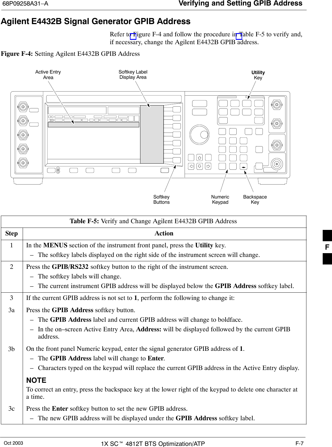
Verifying and Setting GPIB Address68P09258A31–AOct 2003 1X SCt 4812T BTS Optimization/ATP F-7Agilent E4432B Signal Generator GPIB AddressRefer to Figure F-4 and follow the procedure in Table F-5 to verify and,if necessary, change the Agilent E4432B GPIB address.Figure F-4: Setting Agilent E4432B GPIB AddressNumericKeypadSoftkeyButtonsSoftkey LabelDisplay AreaActive EntryAreaBackspaceKeyUtilityKeyTable F-5: Verify and Change Agilent E4432B GPIB AddressStep Action1In the MENUS section of the instrument front panel, press the Utility key.– The softkey labels displayed on the right side of the instrument screen will change.2Press the GPIB/RS232 softkey button to the right of the instrument screen.– The softkey labels will change.– The current instrument GPIB address will be displayed below the GPIB Address softkey label.3If the current GPIB address is not set to 1, perform the following to change it:3a Press the GPIB Address softkey button.– The GPIB Address label and current GPIB address will change to boldface.– In the on–screen Active Entry Area, Address: will be displayed followed by the current GPIBaddress.3b On the front panel Numeric keypad, enter the signal generator GPIB address of 1.– The GPIB Address label will change to Enter.– Characters typed on the keypad will replace the current GPIB address in the Active Entry display.NOTETo correct an entry, press the backspace key at the lower right of the keypad to delete one character ata time.3c Press the Enter softkey button to set the new GPIB address.– The new GPIB address will be displayed under the GPIB Address softkey label. F
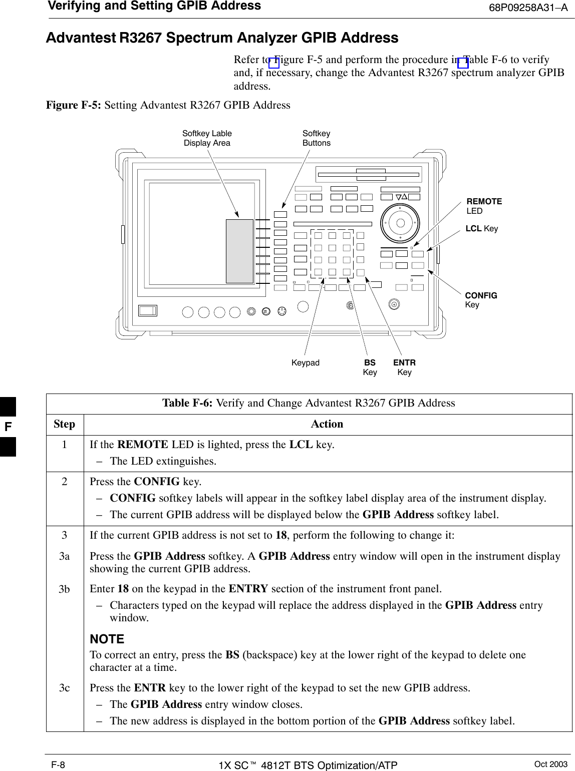
Verifying and Setting GPIB Address 68P09258A31–AOct 20031X SCt 4812T BTS Optimization/ATPF-8Advantest R3267 Spectrum Analyzer GPIB AddressRefer to Figure F-5 and perform the procedure in Table F-6 to verifyand, if necessary, change the Advantest R3267 spectrum analyzer GPIBaddress.Figure F-5: Setting Advantest R3267 GPIB AddressonREMOTELEDLCL KeyCONFIGKeySoftkey LableDisplay AreaSoftkeyButtonsKeypad BSKeyENTRKeyTable F-6: Verify and Change Advantest R3267 GPIB AddressStep Action1If the REMOTE LED is lighted, press the LCL key.– The LED extinguishes.2Press the CONFIG key.–CONFIG softkey labels will appear in the softkey label display area of the instrument display.– The current GPIB address will be displayed below the GPIB Address softkey label.3If the current GPIB address is not set to 18, perform the following to change it:3a Press the GPIB Address softkey. A GPIB Address entry window will open in the instrument displayshowing the current GPIB address.3b Enter 18 on the keypad in the ENTRY section of the instrument front panel.– Characters typed on the keypad will replace the address displayed in the GPIB Address entrywindow.NOTETo correct an entry, press the BS (backspace) key at the lower right of the keypad to delete onecharacter at a time.3c Press the ENTR key to the lower right of the keypad to set the new GPIB address.– The GPIB Address entry window closes.– The new address is displayed in the bottom portion of the GPIB Address softkey label. F
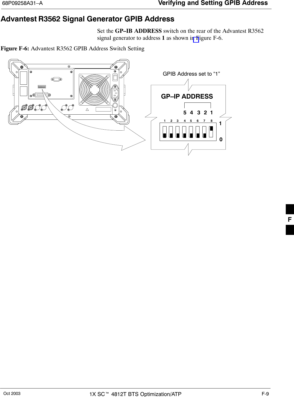
Verifying and Setting GPIB Address68P09258A31–AOct 2003 1X SCt 4812T BTS Optimization/ATP F-9Advantest R3562 Signal Generator GPIB AddressSet the GP–IB ADDRESS switch on the rear of the Advantest R3562signal generator to address 1 as shown in Figure F-6.Figure F-6: Advantest R3562 GPIB Address Switch Setting123 4567 854321GP–IP ADDRESS10GPIB Address set to “1”F
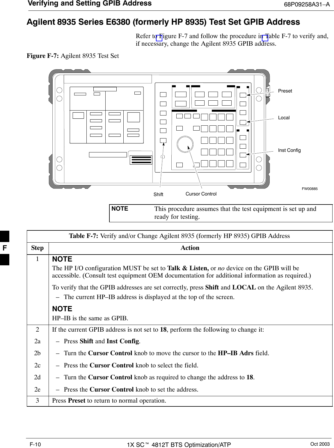
Verifying and Setting GPIB Address 68P09258A31–AOct 20031X SCt 4812T BTS Optimization/ATPF-10Agilent 8935 Series E6380 (formerly HP 8935) Test Set GPIB AddressRefer to Figure F-7 and follow the procedure in Table F-7 to verify and,if necessary, change the Agilent 8935 GPIB address.Figure F-7: Agilent 8935 Test SetFW00885PresetCursor ControlShiftInst ConfigLocalNOTE This procedure assumes that the test equipment is set up andready for testing.Table F-7: Verify and/or Change Agilent 8935 (formerly HP 8935) GPIB AddressStep Action1NOTEThe HP I/O configuration MUST be set to Talk & Listen, or no device on the GPIB will beaccessible. (Consult test equipment OEM documentation for additional information as required.)To verify that the GPIB addresses are set correctly, press Shift and LOCAL on the Agilent 8935.– The current HP–IB address is displayed at the top of the screen.NOTEHP–IB is the same as GPIB.2If the current GPIB address is not set to 18, perform the following to change it:2a – Press Shift and Inst Config.2b – Turn the Cursor Control knob to move the cursor to the HP–IB Adrs field.2c – Press the Cursor Control knob to select the field.2d – Turn the Cursor Control knob as required to change the address to 18.2e – Press the Cursor Control knob to set the address.3 Press Preset to return to normal operation.F
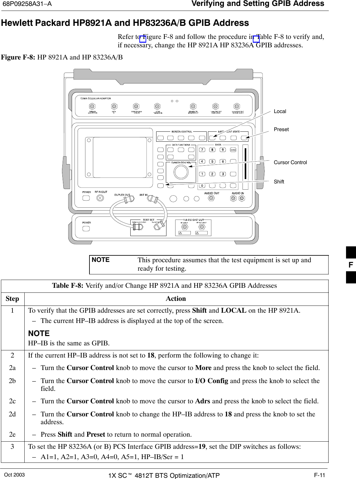
Verifying and Setting GPIB Address68P09258A31–AOct 2003 1X SCt 4812T BTS Optimization/ATP F-11Hewlett Packard HP8921A and HP83236A/B GPIB AddressRefer to Figure F-8 and follow the procedure in Table F-8 to verify and,if necessary, change the HP 8921A HP 83236A GPIB addresses.Figure F-8: HP 8921A and HP 83236A/BPresetCursor ControlShiftLocalNOTE This procedure assumes that the test equipment is set up andready for testing.Table F-8: Verify and/or Change HP 8921A and HP 83236A GPIB AddressesStep Action1To verify that the GPIB addresses are set correctly, press Shift and LOCAL on the HP 8921A.– The current HP–IB address is displayed at the top of the screen.NOTEHP–IB is the same as GPIB.2If the current HP–IB address is not set to 18, perform the following to change it:2a – Turn the Cursor Control knob to move the cursor to More and press the knob to select the field.2b – Turn the Cursor Control knob to move the cursor to I/O Config and press the knob to select thefield.2c – Turn the Cursor Control knob to move the cursor to Adrs and press the knob to select the field.2d – Turn the Cursor Control knob to change the HP–IB address to 18 and press the knob to set theaddress.2e – Press Shift and Preset to return to normal operation.3To set the HP 83236A (or B) PCS Interface GPIB address=19, set the DIP switches as follows:– A1=1, A2=1, A3=0, A4=0, A5=1, HP–IB/Ser = 1F
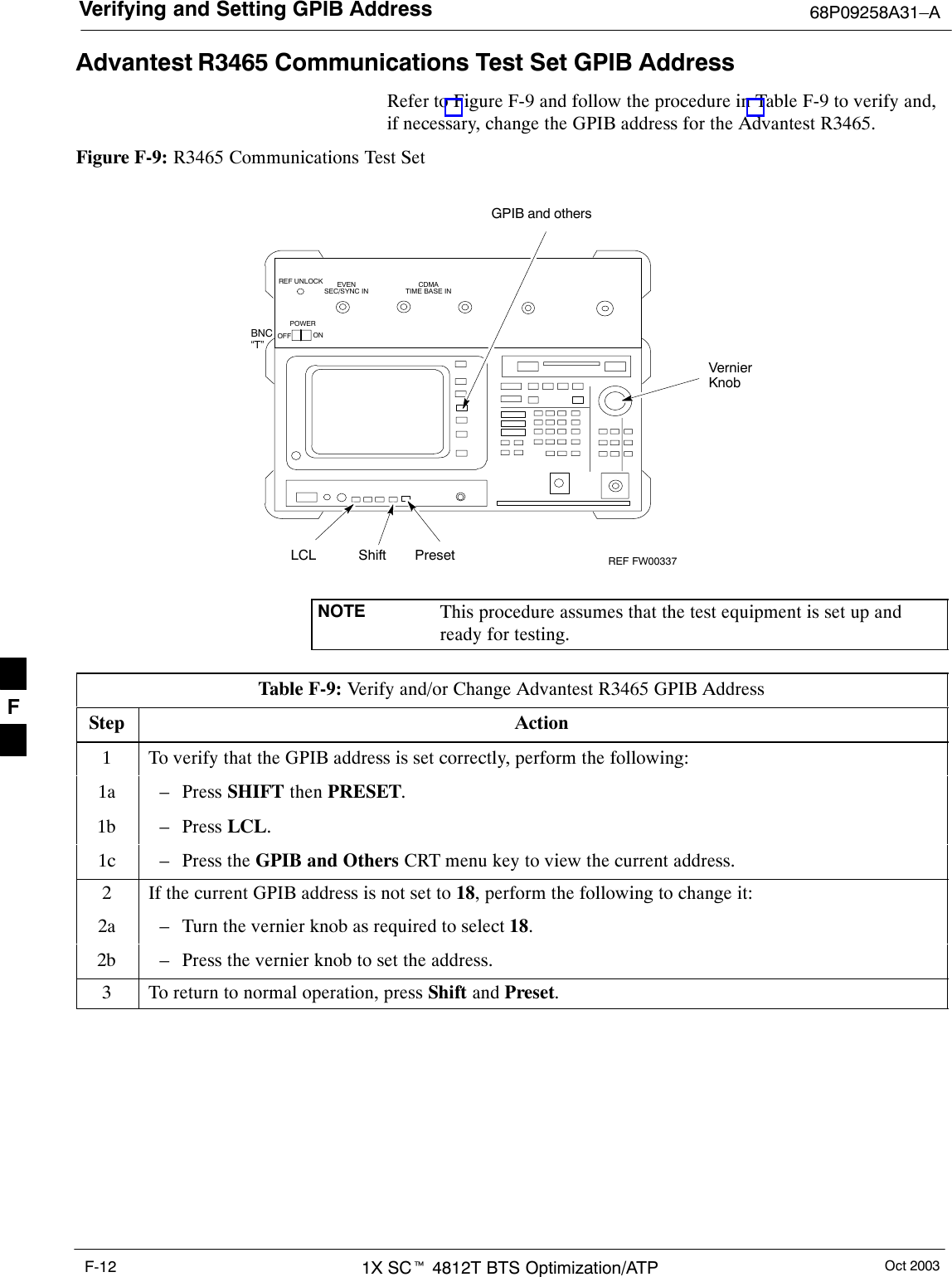
Verifying and Setting GPIB Address 68P09258A31–AOct 20031X SCt 4812T BTS Optimization/ATPF-12Advantest R3465 Communications Test Set GPIB AddressRefer to Figure F-9 and follow the procedure in Table F-9 to verify and,if necessary, change the GPIB address for the Advantest R3465.Figure F-9: R3465 Communications Test SetBNC“T”REF UNLOCK EVENSEC/SYNC IN CDMATIME BASE INPOWEROFF ONREF FW00337LCL Shift PresetGPIB and othersVernierKnobNOTE This procedure assumes that the test equipment is set up andready for testing.Table F-9: Verify and/or Change Advantest R3465 GPIB AddressStep Action1To verify that the GPIB address is set correctly, perform the following:1a – Press SHIFT then PRESET.1b – Press LCL.1c – Press the GPIB and Others CRT menu key to view the current address.2If the current GPIB address is not set to 18, perform the following to change it:2a – Turn the vernier knob as required to select 18.2b – Press the vernier knob to set the address.3To return to normal operation, press Shift and Preset.F
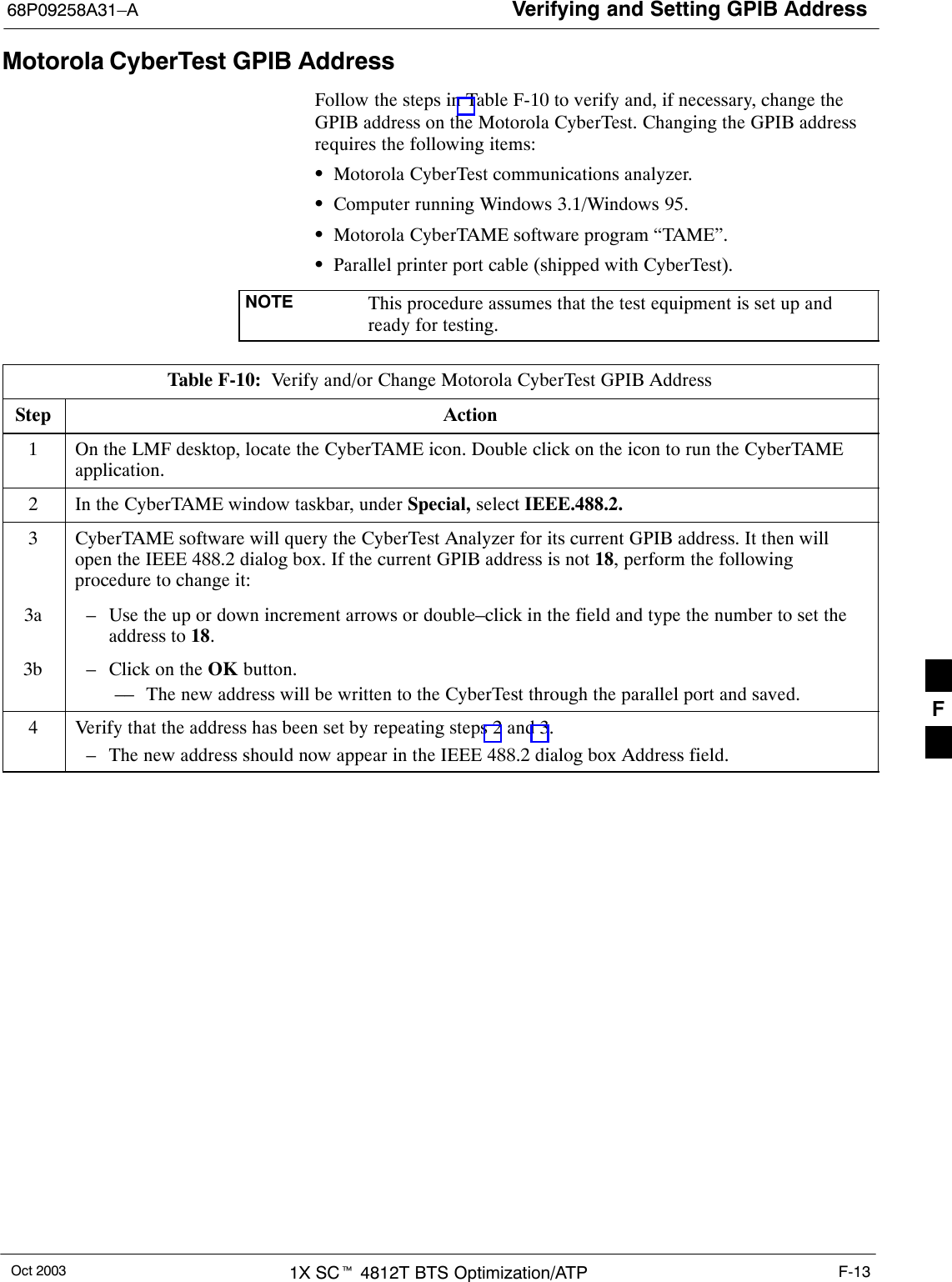
Verifying and Setting GPIB Address68P09258A31–AOct 2003 1X SCt 4812T BTS Optimization/ATP F-13Motorola CyberTest GPIB AddressFollow the steps in Table F-10 to verify and, if necessary, change theGPIB address on the Motorola CyberTest. Changing the GPIB addressrequires the following items:SMotorola CyberTest communications analyzer.SComputer running Windows 3.1/Windows 95.SMotorola CyberTAME software program “TAME”.SParallel printer port cable (shipped with CyberTest).NOTE This procedure assumes that the test equipment is set up andready for testing.Table F-10:  Verify and/or Change Motorola CyberTest GPIB AddressStep Action1On the LMF desktop, locate the CyberTAME icon. Double click on the icon to run the CyberTAMEapplication.2In the CyberTAME window taskbar, under Special, select IEEE.488.2.3CyberTAME software will query the CyberTest Analyzer for its current GPIB address. It then willopen the IEEE 488.2 dialog box. If the current GPIB address is not 18, perform the followingprocedure to change it:3a – Use the up or down increment arrows or double–click in the field and type the number to set theaddress to 18.3b – Click on the OK button.–– The new address will be written to the CyberTest through the parallel port and saved.4Verify that the address has been set by repeating steps 2 and 3.– The new address should now appear in the IEEE 488.2 dialog box Address field.F
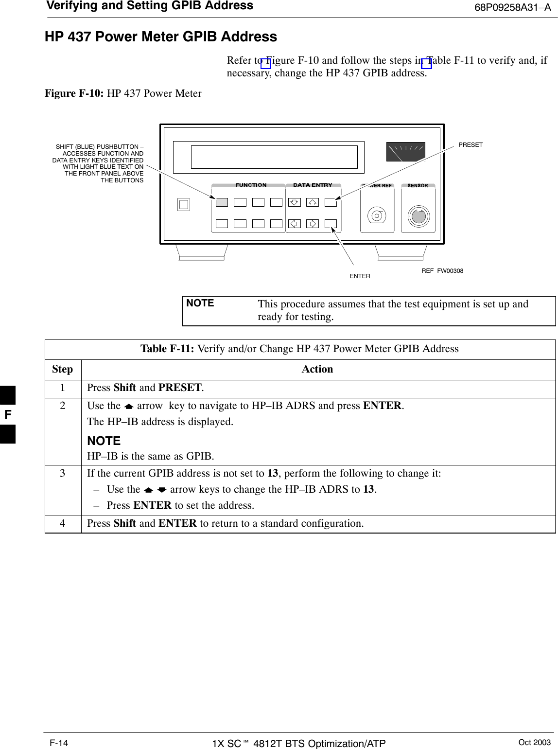
Verifying and Setting GPIB Address 68P09258A31–AOct 20031X SCt 4812T BTS Optimization/ATPF-14HP 437 Power Meter GPIB AddressRefer to Figure F-10 and follow the steps in Table F-11 to verify and, ifnecessary, change the HP 437 GPIB address.Figure F-10: HP 437 Power MeterENTERPRESETSHIFT (BLUE) PUSHBUTTON –ACCESSES FUNCTION ANDDATA ENTRY KEYS IDENTIFIEDWITH LIGHT BLUE TEXT ONTHE FRONT PANEL ABOVETHE BUTTONSFW00308REFNOTE This procedure assumes that the test equipment is set up andready for testing.Table F-11: Verify and/or Change HP 437 Power Meter GPIB AddressStep Action1 Press Shift and PRESET.2Use the y arrow  key to navigate to HP–IB ADRS and press ENTER.The HP–IB address is displayed.NOTEHP–IB is the same as GPIB.3If the current GPIB address is not set to 13, perform the following to change it:– Use the y b arrow keys to change the HP–IB ADRS to 13.– Press ENTER to set the address.4 Press Shift and ENTER to return to a standard configuration. F
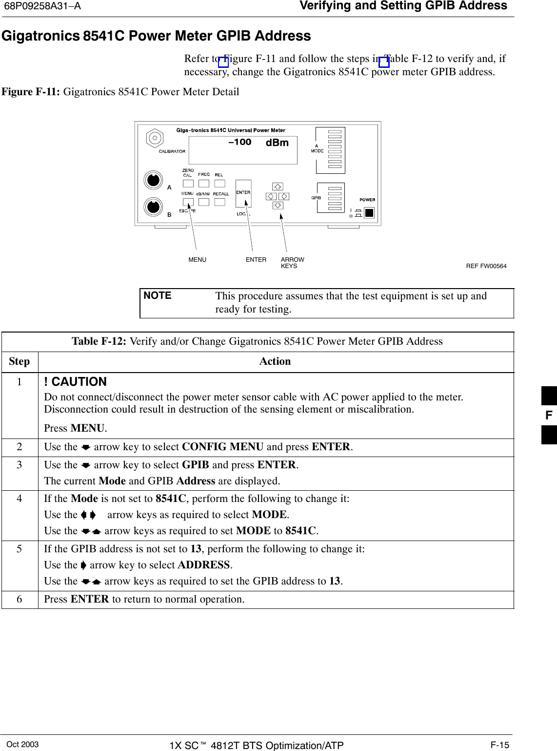
Verifying and Setting GPIB Address68P09258A31–AOct 2003 1X SCt 4812T BTS Optimization/ATP F-15Gigatronics 8541C Power Meter GPIB AddressRefer to Figure F-11 and follow the steps in Table F-12 to verify and, ifnecessary, change the Gigatronics 8541C power meter GPIB address.Figure F-11: Gigatronics 8541C Power Meter DetailMENU ENTER ARROWKEYS1REF FW00564NOTE This procedure assumes that the test equipment is set up andready for testing.Table F-12: Verify and/or Change Gigatronics 8541C Power Meter GPIB AddressStep Action1! CAUTIONDo not connect/disconnect the power meter sensor cable with AC power applied to the meter.Disconnection could result in destruction of the sensing element or miscalibration.Press MENU.2Use the b arrow key to select CONFIG MENU and press ENTER.3Use the b arrow key to select GPIB and press ENTER.The current Mode and GPIB Address are displayed.4If the Mode is not set to 8541C, perform the following to change it:Use the a ’  arrow keys as required to select MODE.Use the by arrow keys as required to set MODE to 8541C.5If the GPIB address is not set to 13, perform the following to change it:Use the ’ arrow key to select ADDRESS.Use the by arrow keys as required to set the GPIB address to 13.6 Press ENTER to return to normal operation.F
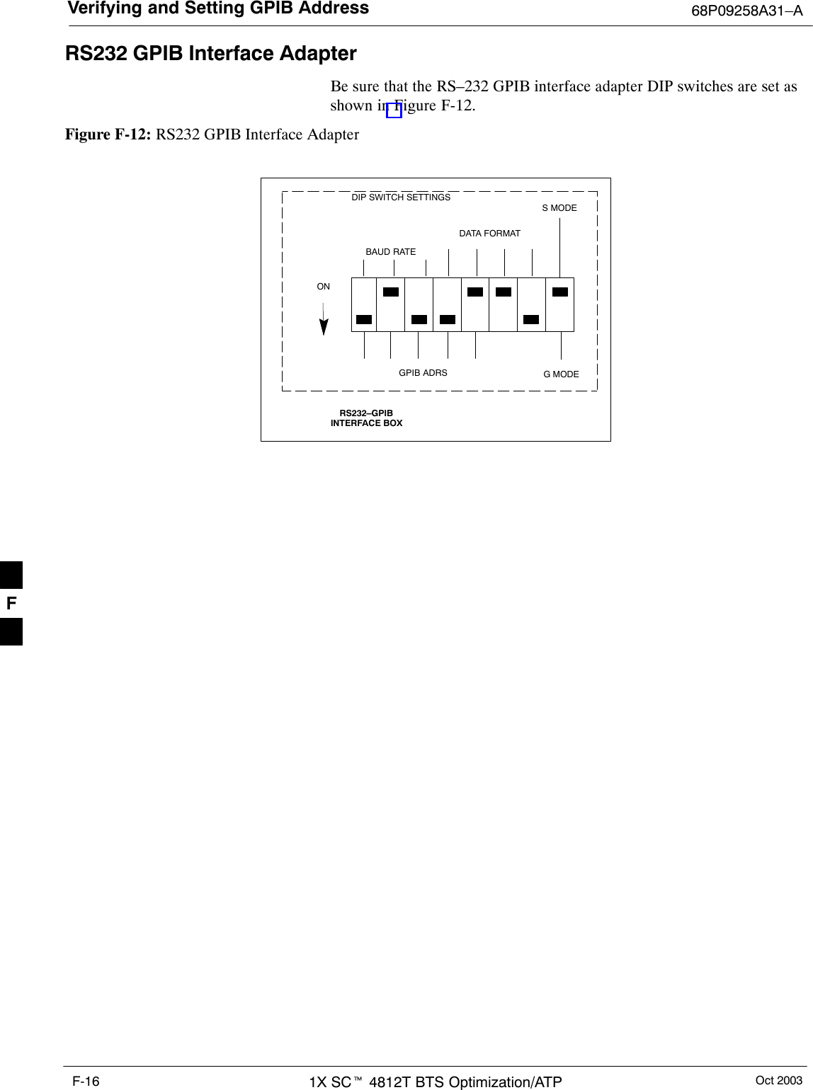
Verifying and Setting GPIB Address 68P09258A31–AOct 20031X SCt 4812T BTS Optimization/ATPF-16RS232 GPIB Interface AdapterBe sure that the RS–232 GPIB interface adapter DIP switches are set asshown in Figure F-12.Figure F-12: RS232 GPIB Interface AdapterRS232–GPIBINTERFACE BOXS MODEDATA FORMATBAUD RATEGPIB ADRSONDIP SWITCH SETTINGSG MODEF
Test Equipment Set-up68P09258A31–AOct 2003 1X SCt 4812T BTS Optimization/ATP F-17Test Equipment Set-upPurposeThis section covers other test equipment and peripherals not covered inChapter 3. Procedures for the manual testing are covered here, alongwith procedures to calibrate the TX and RX cables using the signalgenerator and spectrum analyzer.Equipment Warm upNOTE Warm-up BTS equipment for a minimum of 60 minutes prior toperforming the BTS optimization procedure. This assures BTSsite stability and contributes to optimization accuracy. (Timespent running initial power-up, hardware/firmware audit, and BTS download counts as warm-up time.)CAUTION If any piece of test equipment (i.e., test cable, RF adapter) hasbeen replaced, re-calibration must be performed. Failure to do socould introduce measurement errors, resulting in incorrectmeasurements and degradation to system performance.NOTE Calibration of the communications test set (or equivalent testequipment) must be performed at the site before calibrating theoverall test set. Calibrate the test equipment  after it has beenallowed to warm-up and stabilize for a minimum of 60 minutes.PrerequisitesPrior to performing any of these procedures, all preparations forpreparing the LMF, updating LMF files, and any other pre-calibrationprocedures, as stated in Chapter 3, must have been completed.F
Test Equipment Set-up 68P09258A31–AOct 20031X SCt 4812T BTS Optimization/ATPF-18HP8921A System Connectivity TestFollow the steps in Table F-13 to verify that the connections between thePCS Interface and the HP8921A are correct, and cables are intact. Thesoftware also performs basic functionality checks of each instrument.NOTE Disconnect other GPIB devices, especially system controllers,from the system before running the connectivity software.Table F-13: System ConnectivityStep ActionNOTE– Perform this procedure after test equipment has been allowed to warm–up and stabilize for aminimum of 60 minutes.1Insert HP 83236A Manual Control/System card into memory card slot.2Press the [PRESET] pushbutton.3Press the Screen Control [TESTS] pushbutton to display the “Tests” Main Menu screen.4Position the cursor at Select Procedure Location and select by pressing the cursor control knob.In the Choices selection box, select Card.5Position the cursor at Select Procedure Filename and select by pressing the cursor control knob.In the Choices selection box, select SYS_CONN.6Position the cursor at RUN TEST and select it.The software will prompt you through the connectivity setup.7When the test is complete, position the cursor on STOP TEST and select it; OR press the [K5]pushbutton.8To return to the main menu, press the [K5] pushbutton.F
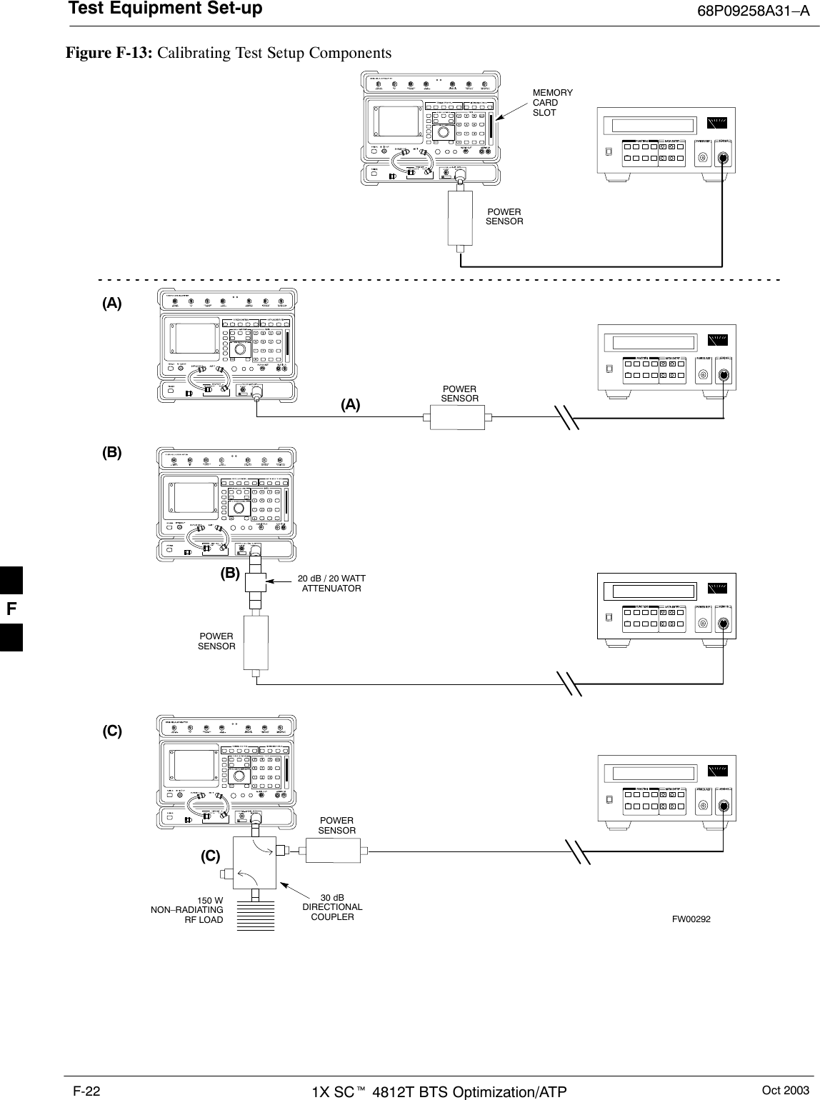
Test Equipment Set-up68P09258A31–AOct 2003 1X SCt 4812T BTS Optimization/ATP F-19Manual Cable Calibration using HP8921 with HP PCS Interface (HP83236)NOTEThis calibration method must be executed with great care. Somelosses are measured close to the minimum limit of the powermeter sensor (–30 dBm).PrerequisitesEnsure the following prerequisites have been met before proceeding:STest equipment to be calibrated has been connected correctly for cablecalibration.STest equipment has been selected and calibrated.Refer to Figure F-13 for location of the components on the PCSInterface and Communications Test Set.Test Equipment Set-upPerform the procedure in Table F-14 to calibrate the test equipmentusing the HP8921 Cellular Communications Analyzer equipped with theHP83236 PCS Interface.Table F-14: Manual Cable Calibration Test Equipment Setup (using the HP PCS Interface)Step ActionNOTEVerify that GPIB controller is turned off.1Insert HP 83236A Manual Control System card into memory card slot (see Figure F-13).2Press the Preset pushbutton.3 Under Screen Controls, press the TESTS pushbutton to display the TESTS (Main Menu) screen.4Position the cursor at Select Procedure Location and select it. In the Choices selection box, selectCARD.5Position the cursor at Select Procedure Filename and select it. In the Choices selection box, selectMANUAL.6Position the cursor at RUN TEST and select it. HP must be in Control Mode Select YES.7If using HP 83236A:Set channel number=<chan#>:– Position cursor at ChannelNumber and select it.– Enter the chan# using the numerickeypad; press [Enter] and thescreen will go blank.– When the screen reappears, thechan# will be displayed on thechannel number line.If using HP 83236B:Set channel frequency:– Position cursor at Frequency Band and press Enter.– Select User Defined Frequency.– Go Back to Previous Menu.– Position the cursor to 83236 generator frequency andenter actual RX frequency.– Position the cursor to 83236 analyzer frequency andenter actual TX frequency.8Set RF Generator level:– Position the cursor at RF Generator Level and select it.– Enter –10 using the numeric keypad; press [Enter] and the screen will go blank.– When the screen reappears, the value –10 dBm will be displayed on the RF Generator Level line.. . . continued on next pageF
Test Equipment Set-up 68P09258A31–AOct 20031X SCt 4812T BTS Optimization/ATPF-20Table F-14: Manual Cable Calibration Test Equipment Setup (using the HP PCS Interface)Step Action9Set the user fixed Attenuation Setting to 0 dBm:– Position cursor at Analyzer Attenuation and select it– Position cursor at User Fixed Atten Settings and select it.– Enter 0 (zero) using the numeric keypad and press [Enter].10 Select Back to Previous Menu.11 Record the HP83236 Generator Frequency Level:Record the HP83236B Generator Frequency Level:– Position cursor at Show Frequency and Level Details and select it.– Under HP83236 Frequencies and Levels, record the Generator Level.– Under HP83236B Frequencies and Levels, record the Generator Frequency Level(1850 – 1910 MHz for 1.9 GHz or 1750 – 1780 for 1.7 GHz).– Position cursor at Prev Menu and select it.12 Click on Pause for Manual Measurement.13 Connect the power sensor directly to the RF OUT ONLY port of the PCS Interface.14 On the HP8921A, under To Screen, select CDMA GEN.15 Move the cursor to the Amplitude field and click on the Amplitude value.16 Increase the Amplitude value until the power meter reads 0 dBm ±0.2 dB.NOTEThe Amplitude value can be increased coarsely until 0 dBM is reached; then fine tune the amplitudeby adjusting the Increment Set to 0.1 dBm and targeting in on 0 dBm.17 Disconnect the power sensor from the RF OUT ONLY port of the PCS Interface.NOTEThe Power Meter sensor’s lower limit is –30 dBm. Thus, only components having losses ≤30 dBshould be measured using this method. For further accuracy, always re-zero the power meterbefore connecting the power sensor to the component being calibrated. After connecting thepower sensor to the component, record the calibrated loss immediately.18 Disconnect all components in the test setup and calibrate each one separately by connecting eachcomponent, one-at-a-time, between the RF OUT ONLY PORT and the power sensor (see Figure F-13,Setups A, B, or C). Record the calibrated loss value displayed on the power meter.SExample: (A) Test Cable(s) = –1.4 dB(B) 20 dB Attenuator  = –20.1 dB(B) Directional Coupler = –29.8 dB19 After all components are calibrated, reassemble all components together and calculate the total testsetup loss by adding up all the individual losses:SExample: Total test setup loss = –1.4 –29.8 –20.1 = –51.3 dB.This calculated value will be used in the next series of tests.20 Under Screen Controls press the TESTS button to display the TESTS (Main Menu) screen.21 Select Continue (K2).22 Select RF Generator Level and set to –119 dBm.. . . continued on next pageF
Test Equipment Set-up68P09258A31–AOct 2003 1X SCt 4812T BTS Optimization/ATP F-21Table F-14: Manual Cable Calibration Test Equipment Setup (using the HP PCS Interface)Step Action23 Click on Pause for Manual Measurement.24 Verify the HP8921A Communication Analyzer/83203A CDMA interface setup is as follows (fieldsnot indicated remain at default):SVerify the GPIB (HP–IB) address:– under To Screen, select More– select IO CONFIG– Set HP–IB Adrs to 18– set Mode to Talk&LstnSVerify the HP8921A is displaying frequency (instead of RF channel)– Press the blue [SHIFT] button, then press the Screen Control [DUPLEX] button; this switches tothe CONFIG (CONFIGURE) screen.– Use the cursor control to set RF Display to Freq25 Refer to Table 3-31 for assistance in manually setting the cable loss values into the LMF. F
Test Equipment Set-up 68P09258A31–AOct 20031X SCt 4812T BTS Optimization/ATPF-22Figure F-13: Calibrating Test Setup Components(A)(C)POWERSENSOR(A)POWERSENSOR(C)30 dBDIRECTIONALCOUPLER150 WNON–RADIATINGRF LOADPOWERSENSOR(B)POWERSENSOR(B)MEMORYCARDSLOT20 dB / 20 WATTATTENUATORFW00292F
Test Equipment Set-up68P09258A31–AOct 2003 1X SCt 4812T BTS Optimization/ATP F-23HP PCS Interface Test Equipment Setup for Manual TestingFollow the procedure in Table F-15 to setup the HP PCS Interface Boxfor manual testing.Table F-15: HP PCS Interface Test Equipment Setup for Manual TestingnStep ActionNOTEVerify GPIB controller is turned off.1Insert HP83236B Manual Control/System card into the memory card slot.2 Under Screen Controls, press the [TESTS] push-button to display the TESTS (Main Menu)screen.3Position the cursor at Select Procedure Location and select. In the Choices selection box, selectCARD.4Position the cursor at Select Procedure Filename and select. In the Choices selection box, selectMANUAL.5Position the cursor at RUN TEST and select OR press the K1 push-button.6Set channel number=<chan#>:– Position cursor at Channel Number and select.– Enter the chan# using the numeric keypad and then press [Enter] (the screen will blank).– When the screen reappears, the chan# will be displayed on the channel number line.NOTEIf using a TMPC with Tower Top Amplifier (TTA) skip Step 7.7SSet RF Generator level= –119 dBm + Cal factorExample: –119 dBm + 2 dB = –117 dBmSContinue with Step 9 (skip Step 8).8Set RF Generator level= –116 dBm + Cal factor.Example: –116 dBm + 2 dB = –114 dBm9Set the user fixed Attenuation Setting to 0 dB:– Position cursor at RF Generator Level and select.– Position  cursor at User Fixed Atten Settings and select.– Enter 0 (zero) using the numeric keypad and press [Enter].10 Select Back to Previous Menu.11 Select Quit, then select Yes.F
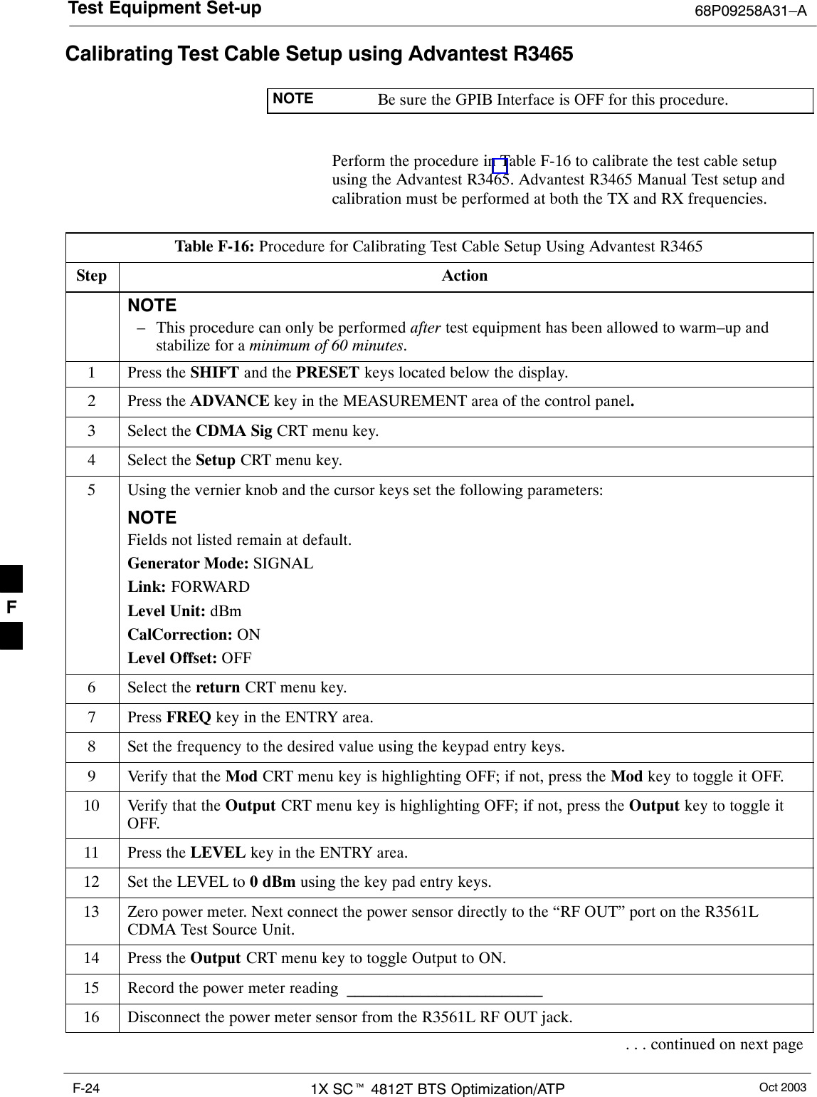
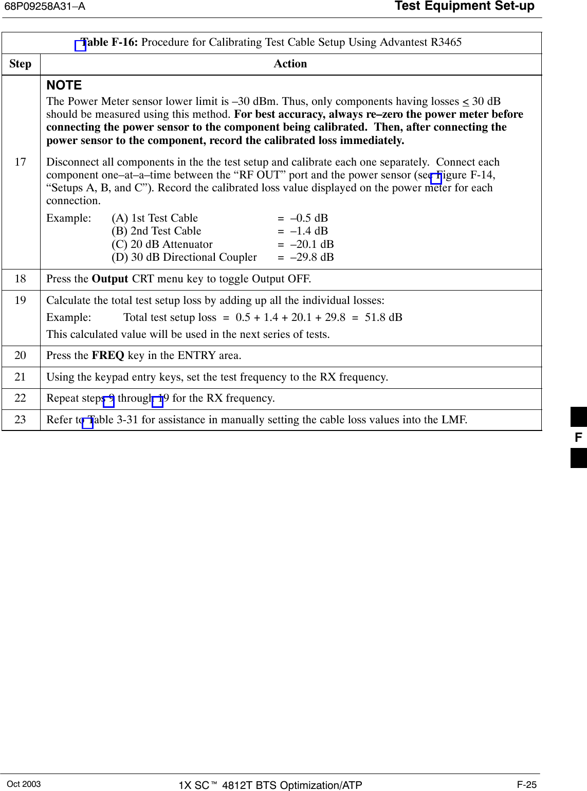
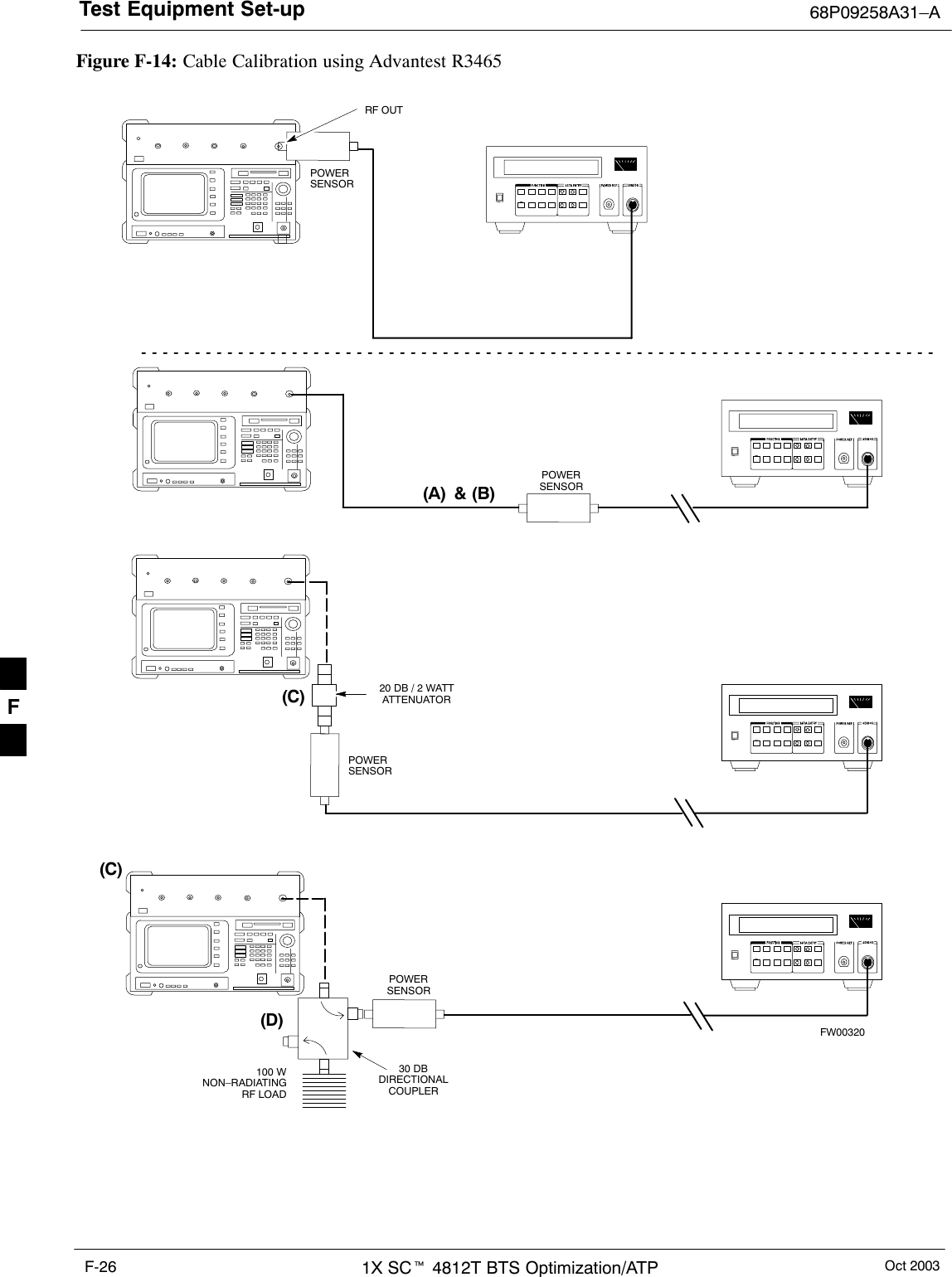
Test Equipment Set-up 68P09258A31–AOct 20031X SCt 4812T BTS Optimization/ATPF-24Calibrating Test Cable Setup using Advantest R3465NOTE Be sure the GPIB Interface is OFF for this procedure.Perform the procedure in Table F-16 to calibrate the test cable setupusing the Advantest R3465. Advantest R3465 Manual Test setup andcalibration must be performed at both the TX and RX frequencies.Table F-16: Procedure for Calibrating Test Cable Setup Using Advantest R3465Step ActionNOTE– This procedure can only be performed after test equipment has been allowed to warm–up andstabilize for a minimum of 60 minutes.1Press the SHIFT and the PRESET keys located below the display.2Press the ADVANCE key in the MEASUREMENT area of the control panel.3Select the CDMA Sig CRT menu key.4Select the Setup CRT menu key.5Using the vernier knob and the cursor keys set the following parameters:NOTEFields not listed remain at default.Generator Mode: SIGNALLink: FORWARDLevel Unit: dBmCalCorrection: ONLevel Offset: OFF6Select the return CRT menu key.7 Press FREQ key in the ENTRY area.8Set the frequency to the desired value using the keypad entry keys.9Verify that the Mod CRT menu key is highlighting OFF; if not, press the Mod key to toggle it OFF.10 Verify that the Output CRT menu key is highlighting OFF; if not, press the Output key to toggle itOFF.11 Press the LEVEL key in the ENTRY area.12 Set the LEVEL to 0 dBm using the key pad entry keys.13 Zero power meter. Next connect the power sensor directly to the “RF OUT” port on the R3561LCDMA Test Source Unit.14 Press the Output CRT menu key to toggle Output to ON.15 Record the power meter reading  ________________________16 Disconnect the power meter sensor from the R3561L RF OUT jack.. . . continued on next pageF
Test Equipment Set-up68P09258A31–AOct 2003 1X SCt 4812T BTS Optimization/ATP F-25Table F-16: Procedure for Calibrating Test Cable Setup Using Advantest R3465Step ActionNOTEThe Power Meter sensor lower limit is –30 dBm. Thus, only components having losses < 30 dBshould be measured using this method. For best accuracy, always re–zero the power meter beforeconnecting the power sensor to the component being calibrated.  Then, after connecting thepower sensor to the component, record the calibrated loss immediately.17 Disconnect all components in the the test setup and calibrate each one separately.  Connect eachcomponent one–at–a–time between the “RF OUT” port and the power sensor (see Figure F-14,“Setups A, B, and C”). Record the calibrated loss value displayed on the power meter for eachconnection.Example:  (A) 1st Test Cable =  –0.5 dB(B) 2nd Test Cable  =  –1.4 dB(C) 20 dB Attenuator  =  –20.1 dB(D) 30 dB Directional Coupler  =  –29.8 dB18 Press the Output CRT menu key to toggle Output OFF.19 Calculate the total test setup loss by adding up all the individual losses:Example:  Total test setup loss  =  0.5 + 1.4 + 20.1 + 29.8  =  51.8 dBThis calculated value will be used in the next series of tests.20 Press the FREQ key in the ENTRY area.21 Using the keypad entry keys, set the test frequency to the RX frequency.22 Repeat steps 9 through 19 for the RX frequency.23 Refer to Table 3-31 for assistance in manually setting the cable loss values into the LMF. F
Test Equipment Set-up 68P09258A31–AOct 20031X SCt 4812T BTS Optimization/ATPF-26Figure F-14: Cable Calibration using Advantest R3465POWERSENSOR20 DB / 2 WATTATTENUATOR(A)(C)POWERSENSOR(D)30 DBDIRECTIONALCOUPLER(C)100 WNON–RADIATINGRF LOADPOWERSENSORRF OUTPOWERSENSOR& (B)FW00320F
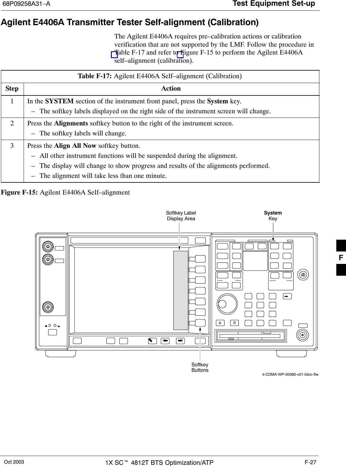
Test Equipment Set-up68P09258A31–AOct 2003 1X SCt 4812T BTS Optimization/ATP F-27Agilent E4406A Transmitter Tester Self-alignment (Calibration)The Agilent E4406A requires pre–calibration actions or calibrationverification that are not supported by the LMF. Follow the procedure inTable F-17 and refer to Figure F-15 to perform the Agilent E4406Aself–alignment (calibration).Table F-17: Agilent E4406A Self–alignment (Calibration)Step Action1In the SYSTEM section of the instrument front panel, press the System key.– The softkey labels displayed on the right side of the instrument screen will change.2Press the Alignments softkey button to the right of the instrument screen.– The softkey labels will change.3Press the Align All Now softkey button.– All other instrument functions will be suspended during the alignment.– The display will change to show progress and results of the alignments performed.– The alignment will take less than one minute.Figure F-15: Agilent E4406A Self–alignmentSystemKeySoftkeyButtonsSoftkey LabelDisplay Areati-CDMA-WP-00080-v01-ildoc-ftwF
Test Equipment Set-up 68P09258A31–AOct 20031X SCt 4812T BTS Optimization/ATPF-28NotesF
Oct 2003 1X SCt 4812T BTS Optimization/ATP G-1Appendix GDownload ROM CodeG
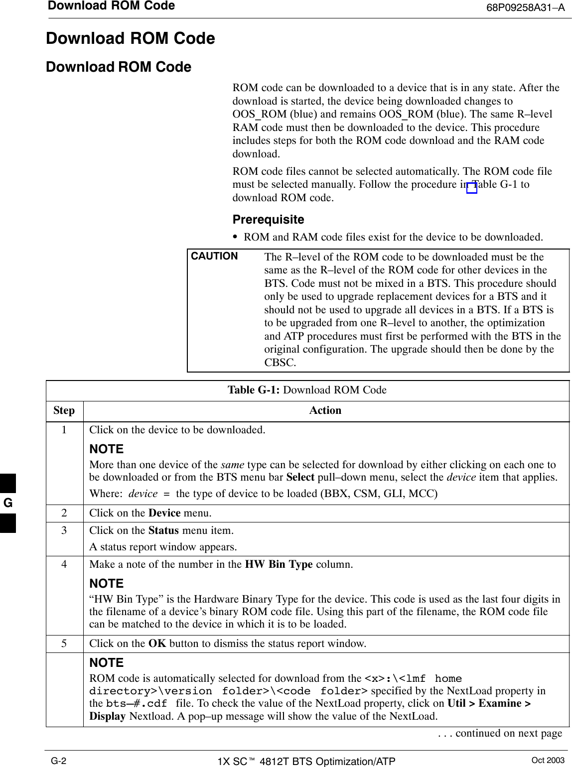
Download ROM Code 68P09258A31–AOct 20031X SCt 4812T BTS Optimization/ATPG-2Download ROM CodeDownload ROM CodeROM code can be downloaded to a device that is in any state. After thedownload is started, the device being downloaded changes toOOS_ROM (blue) and remains OOS_ROM (blue). The same R–levelRAM code must then be downloaded to the device. This procedureincludes steps for both the ROM code download and the RAM codedownload.ROM code files cannot be selected automatically. The ROM code filemust be selected manually. Follow the procedure in Table G-1 todownload ROM code.PrerequisiteSROM and RAM code files exist for the device to be downloaded.CAUTION The R–level of the ROM code to be downloaded must be thesame as the R–level of the ROM code for other devices in theBTS. Code must not be mixed in a BTS. This procedure shouldonly be used to upgrade replacement devices for a BTS and itshould not be used to upgrade all devices in a BTS. If a BTS isto be upgraded from one R–level to another, the optimizationand ATP procedures must first be performed with the BTS in theoriginal configuration. The upgrade should then be done by theCBSC.Table G-1: Download ROM CodeStep Action1Click on the device to be downloaded.NOTEMore than one device of the same type can be selected for download by either clicking on each one tobe downloaded or from the BTS menu bar Select pull–down menu, select the device item that applies.Where:  device  =  the type of device to be loaded (BBX, CSM, GLI, MCC)2Click on the Device menu.3Click on the Status menu item.A status report window appears.4Make a note of the number in the HW Bin Type column.NOTE“HW Bin Type” is the Hardware Binary Type for the device. This code is used as the last four digits inthe filename of a device’s binary ROM code file. Using this part of the filename, the ROM code filecan be matched to the device in which it is to be loaded.5Click on the OK button to dismiss the status report window.NOTEROM code is automatically selected for download from the <x>:\<lmf homedirectory>\version folder>\<code folder> specified by the NextLoad property inthe bts–#.cdf file. To check the value of the NextLoad property, click on Util > Examine >Display Nextload. A pop–up message will show the value of the NextLoad.. . . continued on next pageG
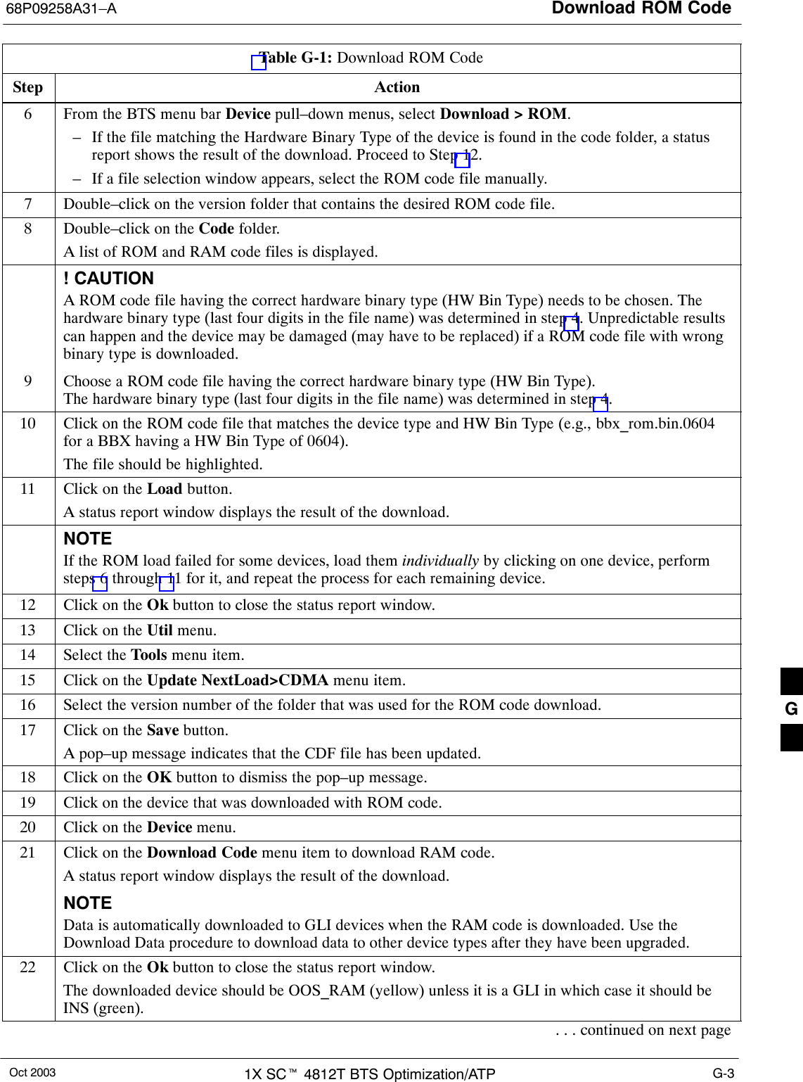
Download ROM Code68P09258A31–AOct 2003 1X SCt 4812T BTS Optimization/ATP G-3Table G-1: Download ROM CodeStep Action6From the BTS menu bar Device pull–down menus, select Download > ROM.– If the file matching the Hardware Binary Type of the device is found in the code folder, a statusreport shows the result of the download. Proceed to Step 12.– If a file selection window appears, select the ROM code file manually.7Double–click on the version folder that contains the desired ROM code file.8Double–click on the Code folder.A list of ROM and RAM code files is displayed.! CAUTIONA ROM code file having the correct hardware binary type (HW Bin Type) needs to be chosen. Thehardware binary type (last four digits in the file name) was determined in step 4. Unpredictable resultscan happen and the device may be damaged (may have to be replaced) if a ROM code file with wrongbinary type is downloaded.9Choose a ROM code file having the correct hardware binary type (HW Bin Type).The hardware binary type (last four digits in the file name) was determined in step 4.10 Click on the ROM code file that matches the device type and HW Bin Type (e.g., bbx_rom.bin.0604for a BBX having a HW Bin Type of 0604).The file should be highlighted.11 Click on the Load button.A status report window displays the result of the download.NOTEIf the ROM load failed for some devices, load them individually by clicking on one device, performsteps 6 through 11 for it, and repeat the process for each remaining device.12 Click on the Ok button to close the status report window.13 Click on the Util menu.14 Select the Tools menu item.15 Click on the Update NextLoad>CDMA menu item.16 Select the version number of the folder that was used for the ROM code download.17 Click on the Save button.A pop–up message indicates that the CDF file has been updated.18 Click on the OK button to dismiss the pop–up message.19 Click on the device that was downloaded with ROM code.20 Click on the Device menu.21 Click on the Download Code menu item to download RAM code.A status report window displays the result of the download.NOTEData is automatically downloaded to GLI devices when the RAM code is downloaded. Use theDownload Data procedure to download data to other device types after they have been upgraded.22 Click on the Ok button to close the status report window.The downloaded device should be OOS_RAM (yellow) unless it is a GLI in which case it should beINS (green).. . . continued on next pageG
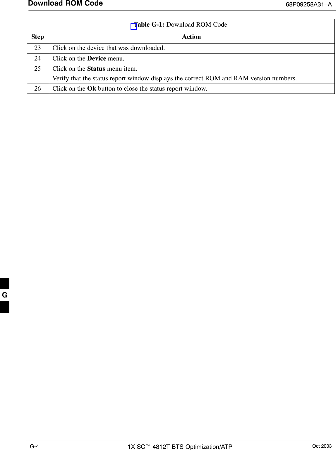
Download ROM Code 68P09258A31–AOct 20031X SCt 4812T BTS Optimization/ATPG-4Table G-1: Download ROM CodeStep Action23 Click on the device that was downloaded.24 Click on the Device menu.25 Click on the Status menu item.Verify that the status report window displays the correct ROM and RAM version numbers.26 Click on the Ok button to close the status report window. G
Oct 2003 1X SCt 4812T BTS Optimization/ATP H-1Appendix HIn–Service CalibrationH
Introduction 68P09258A31–AOct 20031X SCt 4812T BTS Optimization/ATPH-2IntroductionPurposeThis procedure is a guide to expanding your system with multiplecarriers while the system remains in service. This procedure also allowsyou to perform on site maintenance (replace defective boards andrecalibrate) while the remainder of the site stays in service.Motorola recommends that you perform this procedure during amaintenance window.This procedure cannot be performed on BTSs with 4–to–1 combiners.The procedure can only be performed on one side of the BTS at onetime. That is, LPAs 1, 2 ,3, 7, 8, 9 (feed antennas 1, 2, 3) can becalibrated while LPAs 6, 7, 8, 10, 11, 12 (feed antennas 4, 5, 6) remainin service and vice versa.Equipment Warm upNOTE Calibration of the communications test set (or equivalent testequipment) must be performed at the site before calibrating theoverall test set. Calibrate the test equipment  after it has beenallowed to warm-up and stabilize for a minimum of 60 minutes.CAUTION If any piece of test equipment (i.e., test cable, RF adapter) hasbeen replaced, re-calibration must be performed. Failure to do socould introduce measurement errors, causing incorrectmeasurements and degradation to system performance.H
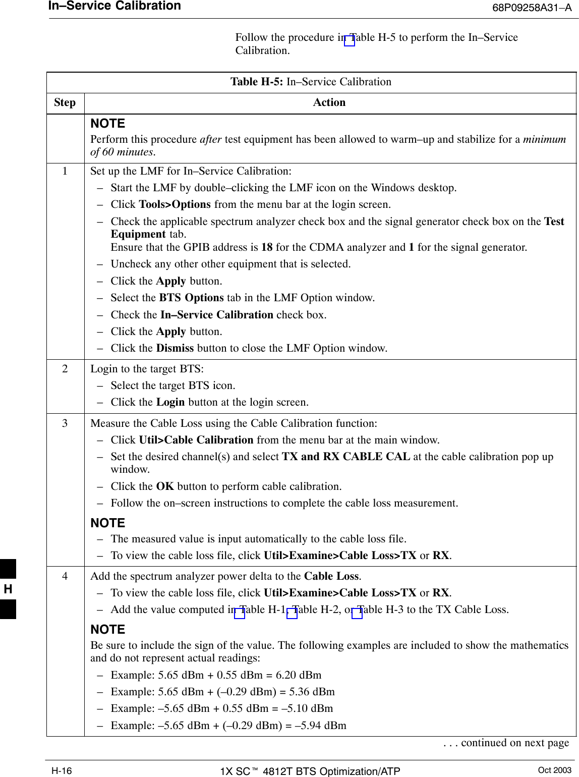
Power Delta Calibration68P09258A31–AOct 2003 1X SCt 4812T BTS Optimization/ATP H-3Power Delta CalibrationPower Delta Calibration IntroductionThe In–service calibration procedure has several differences from anormal calibration procedure. One of these is the use of a spectrumanalyzer instead of a power meter to measure power. Power meters arebroadband measurement devices and cannot be used to measure powerduring In–service Calibration since other carriers are operating. Aspectrum analyzer can be used because it measures power at a givenfrequency. However, measuring power using a spectrum analyzer is lessaccurate than using a power meter. Therefore, you must compensate forthe difference (delta) between the power meter and the spectrumanalyzer.HP8921A Power Delta CalibrationUse the HP8921A Spectrum Analyzer to measure power duringIn–Service Calibration for 800 MHz systems. After the offset value hasbeen calculated, add it to the TX cable loss value.Follow the procedure in Table H-1 to perform the HP8921A Power DeltaCalibration procedure.NOTE This procedure requires two HP8921As.Table H-1: HP8921A Power Delta Calibration ProcedureStep ActionNOTEPerform this procedure after test equipment has been allowed to warm–up and stabilize for a minimumof 60 minutes.1Connect a short RF cable between the HP8921A Duplex Out port and the HP437B power sensor (seeFigure H-1).2Set the HP8921A signal source as follows:– Measure mode to CDMA Generator– Frequency to the CDMA Calibration target frequency– CW RF Path to IQ– Output Port to Dupl– Data Source to Random– Amplitude to 0 dBm3Measure and record the power value reading on the HP437B Power Meter.4Record the Power Meter reading as result A ________________________.5Turn off the source HP8921A signal output, and disconnect the HP437B.NOTELeave the settings on the source HP8921A for convenience in the following steps.6Connect the short RF cable between the source HP8921A Duplex Out port and the measuringHP8921A RF–IN port (see Figure H-2).. . . continued on next pageH
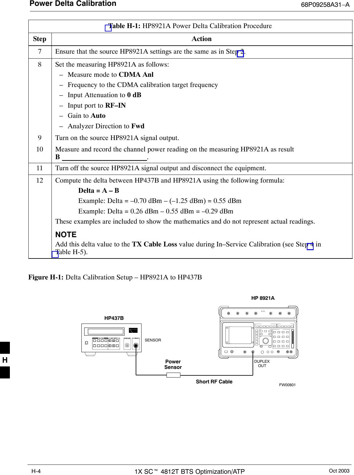
Power Delta Calibration 68P09258A31–AOct 20031X SCt 4812T BTS Optimization/ATPH-4Table H-1: HP8921A Power Delta Calibration ProcedureStep Action7Ensure that the source HP8921A settings are the same as in Step 2.8Set the measuring HP8921A as follows:– Measure mode to CDMA Anl– Frequency to the CDMA calibration target frequency– Input Attenuation to 0 dB– Input port to RF–IN– Gain to Auto– Analyzer Direction to Fwd9Turn on the source HP8921A signal output.10 Measure and record the channel power reading on the measuring HP8921A as resultB ________________________.11 Turn off the source HP8921A signal output and disconnect the equipment.12 Compute the delta between HP437B and HP8921A using the following formula:Delta = A – BExample: Delta = –0.70 dBm – (–1.25 dBm) = 0.55 dBmExample: Delta = 0.26 dBm – 0.55 dBm = –0.29 dBmThese examples are included to show the mathematics and do not represent actual readings.NOTEAdd this delta value to the TX Cable Loss value during In–Service Calibration (see Step 4 inTable H-5). Figure H-1: Delta Calibration Setup – HP8921A to HP437BShort RF CableHP 8921ADUPLEXOUTHP437BPowerSensorSENSORFW00801H
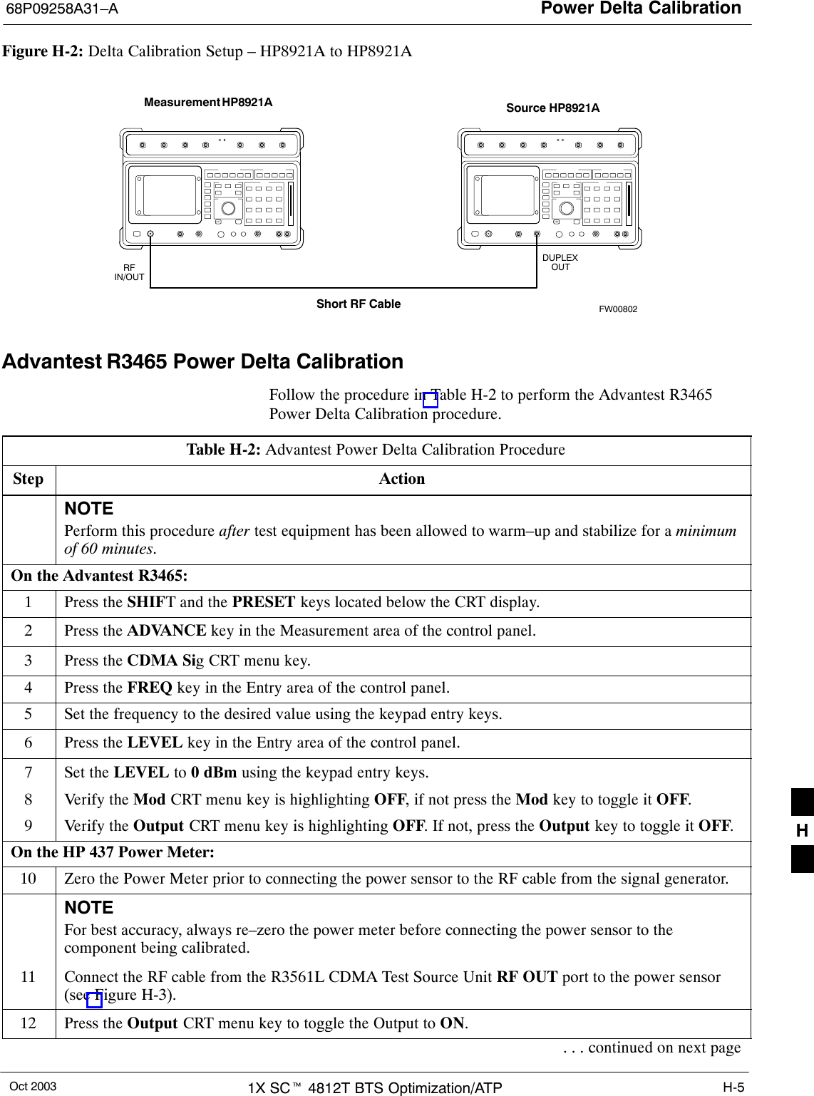
Power Delta Calibration68P09258A31–AOct 2003 1X SCt 4812T BTS Optimization/ATP H-5Figure H-2: Delta Calibration Setup – HP8921A to HP8921AMeasurement HP8921A Source HP8921AShort RF CableDUPLEXOUTRFIN/OUTFW00802Advantest R3465 Power Delta CalibrationFollow the procedure in Table H-2 to perform the Advantest R3465Power Delta Calibration procedure.Table H-2: Advantest Power Delta Calibration ProcedureStep ActionNOTEPerform this procedure after test equipment has been allowed to warm–up and stabilize for a minimumof 60 minutes.On the Advantest R3465:1Press the SHIFT and the PRESET keys located below the CRT display.2Press the ADVANCE key in the Measurement area of the control panel.3Press the CDMA Sig CRT menu key.4Press the FREQ key in the Entry area of the control panel.5Set the frequency to the desired value using the keypad entry keys.6Press the LEVEL key in the Entry area of the control panel.7Set the LEVEL to 0 dBm using the keypad entry keys.8Verify the Mod CRT menu key is highlighting OFF, if not press the Mod key to toggle it OFF.9Verify the Output CRT menu key is highlighting OFF. If not, press the Output key to toggle it OFF.On the HP 437 Power Meter:10 Zero the Power Meter prior to connecting the power sensor to the RF cable from the signal generator.NOTEFor best accuracy, always re–zero the power meter before connecting the power sensor to thecomponent being calibrated.11 Connect the RF cable from the R3561L CDMA Test Source Unit RF OUT port to the power sensor(see Figure H-3).12 Press the Output CRT menu key to toggle the Output to ON.. . . continued on next pageH
Power Delta Calibration 68P09258A31–AOct 20031X SCt 4812T BTS Optimization/ATPH-6Table H-2: Advantest Power Delta Calibration ProcedureStep Action13 Record the Power Meter reading as result A ________________________.14 Press the Output CRT menu key to toggle the Output to OFF.15 Connect the RF cable from the R3561L CDMA Test Source Unit RF OUT port to the SpectrumAnalyzer INPUT Port (see Figure H-4).16 Press the Output CRT menu key to change the Output to ON.17 Press the CW key in the Measurement area of the control panel.18 Press the LEVEL key in the Entry area of the control panel.19 Set the REF LEVEL to 10 dBm using the keypad entry keys.20 Press the dB/div CRT menu key.21 Press the 10 dB/div CRT menu key.22 Press the FREQ key in Entry area of the control panel.23 Set the frequency to the desired value using the keypad entry keys.24 Press the more 1/2 CRT menu key.25 Press the Preselector CRT menu key to highlight 3.0G.26 Press the FORMAT key in the Display Control area of the control panel.27 Press the TRACE CRT menu key.28 Press the AVG A CRT menu key.29 Set AVG to 20 using keypad entry keys.30 Press the return CRT menu key.31 Press the SPAN key in the Entry area of the control panel.32 Press the Zero Span CRT menu key.33 Press the BW key in the Entry area of the control panel.34 Press the RBW CRT menu key to highlight MNL.35 Set RBW to 30 kHz using keypad entry keys.36 Press the VBW CRT menu key to highlight MNL.37 Set VBW to 1 MHz using keypad entry keys.38 Press the Marker ON key in the Display Control area of the control panel.39 Record the Marker Level reading as result B ________________________.. . . continued on next pageH
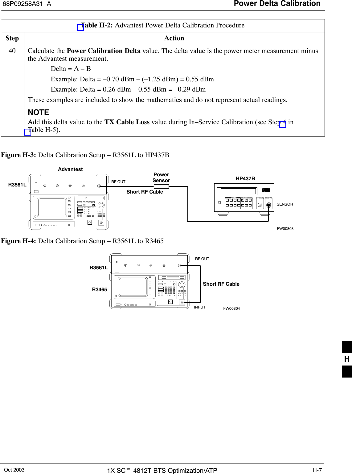
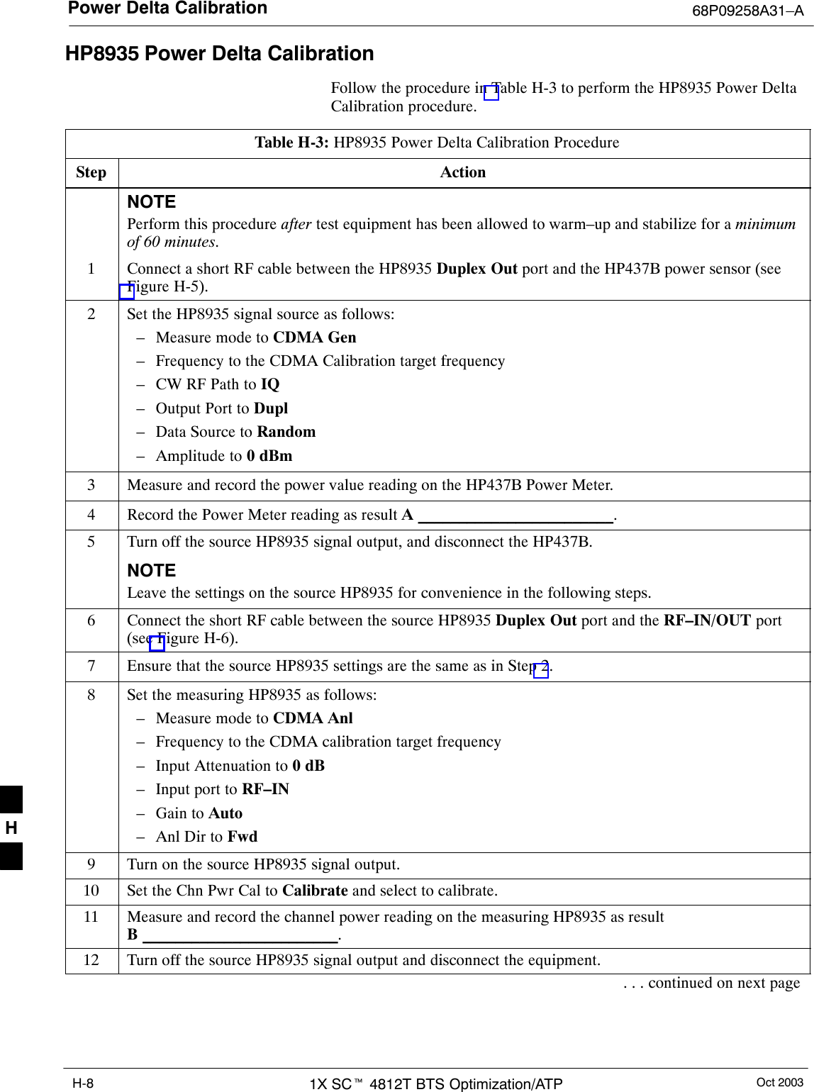
Power Delta Calibration68P09258A31–AOct 2003 1X SCt 4812T BTS Optimization/ATP H-7Table H-2: Advantest Power Delta Calibration ProcedureStep Action40 Calculate the Power Calibration Delta value. The delta value is the power meter measurement minusthe Advantest measurement.Delta = A – BExample: Delta = –0.70 dBm – (–1.25 dBm) = 0.55 dBmExample: Delta = 0.26 dBm – 0.55 dBm = –0.29 dBmThese examples are included to show the mathematics and do not represent actual readings.NOTEAdd this delta value to the TX Cable Loss value during In–Service Calibration (see Step 4 inTable H-5). Figure H-3: Delta Calibration Setup – R3561L to HP437BAdvantestPowerSensorRF OUTShort RF CableHP437BSENSORR3561LFW00803Figure H-4: Delta Calibration Setup – R3561L to R3465R3561LRF OUTINPUTShort RF CableR3465FW00804H
Power Delta Calibration 68P09258A31–AOct 20031X SCt 4812T BTS Optimization/ATPH-8HP8935 Power Delta CalibrationFollow the procedure in Table H-3 to perform the HP8935 Power DeltaCalibration procedure.Table H-3: HP8935 Power Delta Calibration ProcedureStep ActionNOTEPerform this procedure after test equipment has been allowed to warm–up and stabilize for a minimumof 60 minutes.1Connect a short RF cable between the HP8935 Duplex Out port and the HP437B power sensor (seeFigure H-5).2Set the HP8935 signal source as follows:– Measure mode to CDMA Gen– Frequency to the CDMA Calibration target frequency– CW RF Path to IQ– Output Port to Dupl– Data Source to Random– Amplitude to 0 dBm3Measure and record the power value reading on the HP437B Power Meter.4Record the Power Meter reading as result A ________________________.5Turn off the source HP8935 signal output, and disconnect the HP437B.NOTELeave the settings on the source HP8935 for convenience in the following steps.6Connect the short RF cable between the source HP8935 Duplex Out port and the RF–IN/OUT port(see Figure H-6).7Ensure that the source HP8935 settings are the same as in Step 2.8Set the measuring HP8935 as follows:– Measure mode to CDMA Anl– Frequency to the CDMA calibration target frequency– Input Attenuation to 0 dB– Input port to RF–IN– Gain to Auto– Anl Dir to Fwd9Turn on the source HP8935 signal output.10 Set the Chn Pwr Cal to Calibrate and select to calibrate.11 Measure and record the channel power reading on the measuring HP8935 as resultB ________________________.12 Turn off the source HP8935 signal output and disconnect the equipment.. . . continued on next pageH
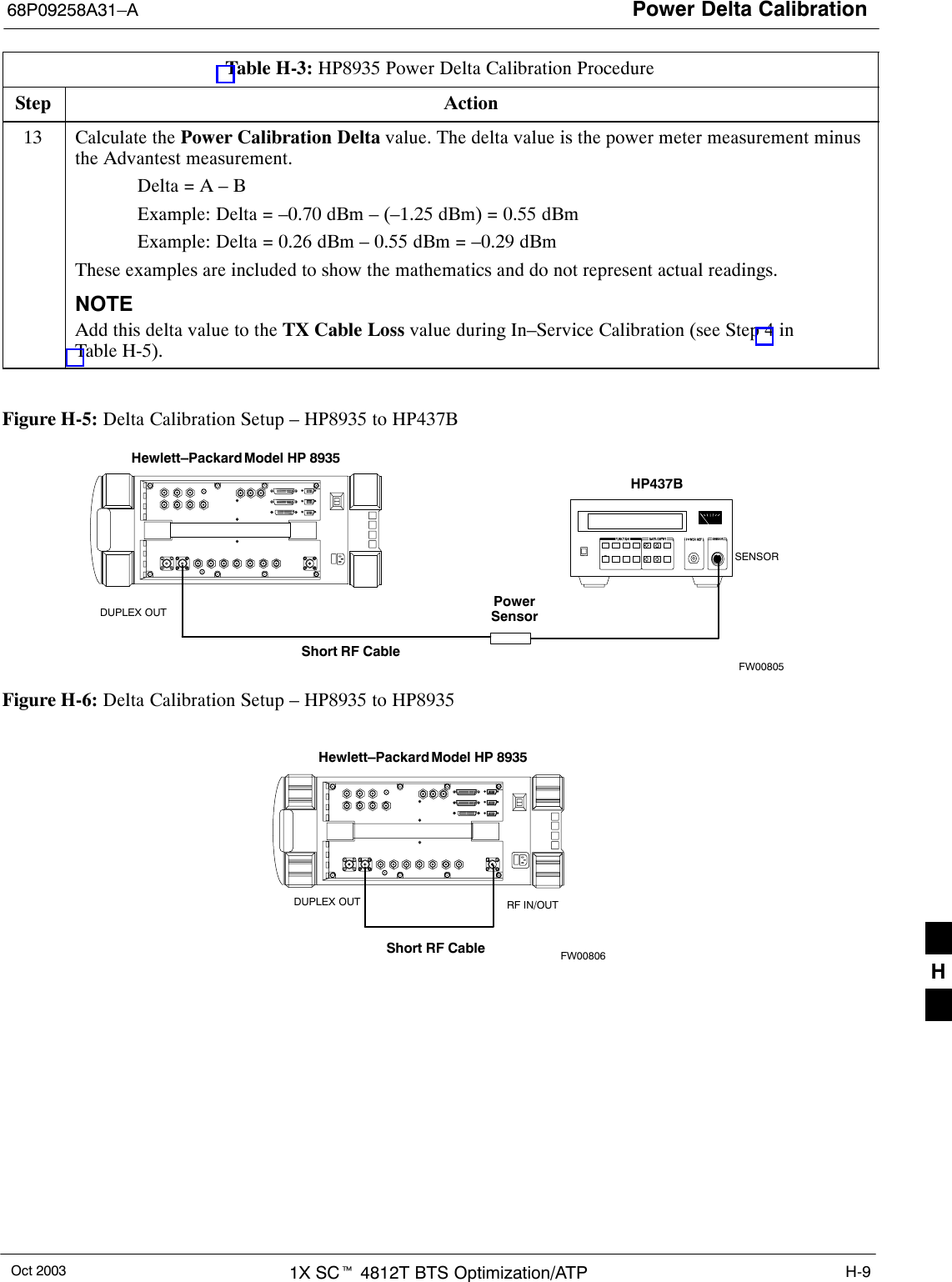
Power Delta Calibration68P09258A31–AOct 2003 1X SCt 4812T BTS Optimization/ATP H-9Table H-3: HP8935 Power Delta Calibration ProcedureStep Action13 Calculate the Power Calibration Delta value. The delta value is the power meter measurement minusthe Advantest measurement.Delta = A – BExample: Delta = –0.70 dBm – (–1.25 dBm) = 0.55 dBmExample: Delta = 0.26 dBm – 0.55 dBm = –0.29 dBmThese examples are included to show the mathematics and do not represent actual readings.NOTEAdd this delta value to the TX Cable Loss value during In–Service Calibration (see Step 4 inTable H-5). Figure H-5: Delta Calibration Setup – HP8935 to HP437BPowerSensorHewlett–Packard Model HP 8935DUPLEX OUTShort RF CableHP437BSENSORFW00805Figure H-6: Delta Calibration Setup – HP8935 to HP8935Hewlett–Packard Model HP 8935Short RF CableDUPLEX OUT RF IN/OUTFW00806H
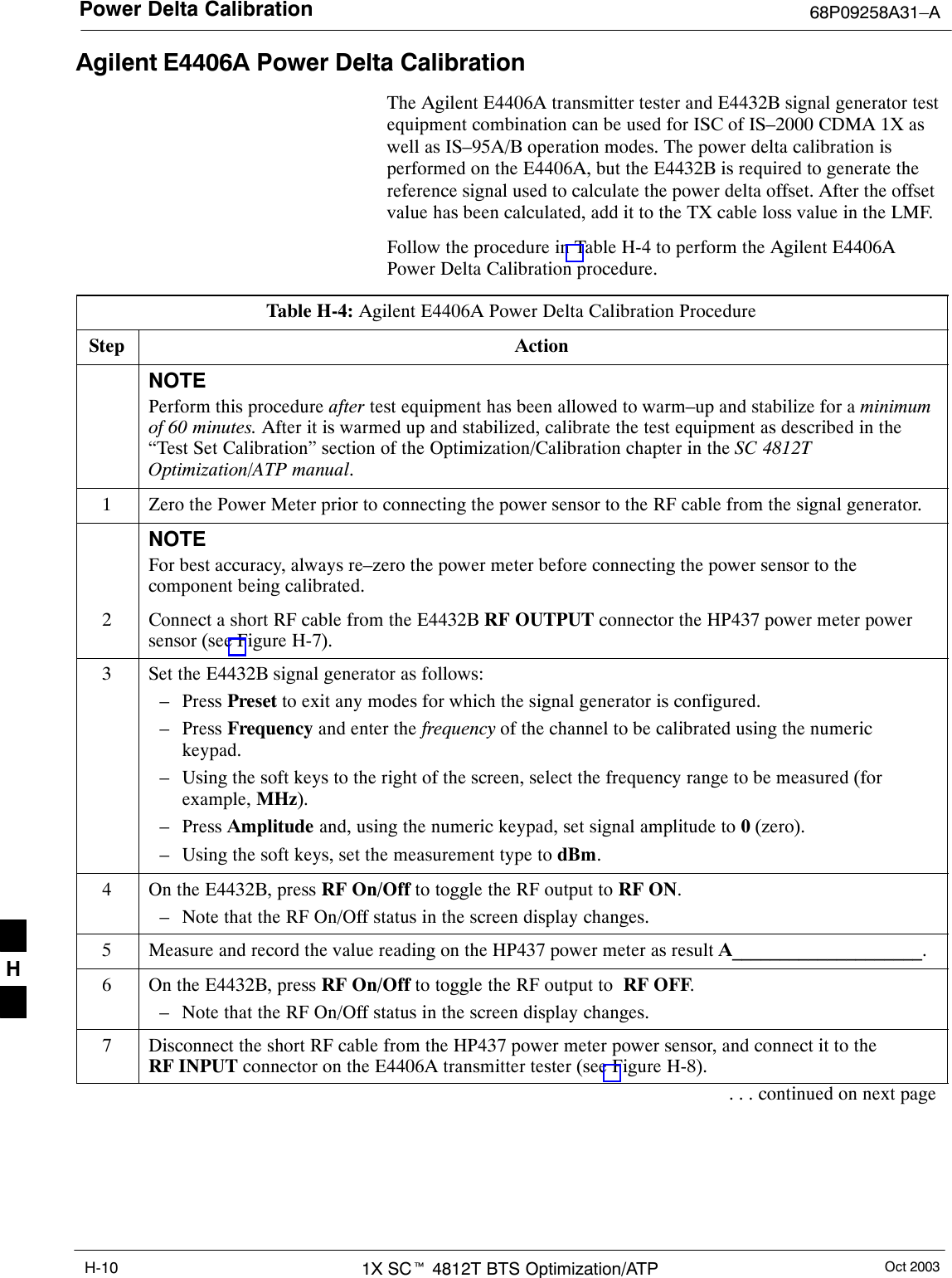
Power Delta Calibration 68P09258A31–AOct 20031X SCt 4812T BTS Optimization/ATPH-10Agilent E4406A Power Delta CalibrationThe Agilent E4406A transmitter tester and E4432B signal generator testequipment combination can be used for ISC of IS–2000 CDMA 1X aswell as IS–95A/B operation modes. The power delta calibration isperformed on the E4406A, but the E4432B is required to generate thereference signal used to calculate the power delta offset. After the offsetvalue has been calculated, add it to the TX cable loss value in the LMF.Follow the procedure in Table H-4 to perform the Agilent E4406APower Delta Calibration procedure.Table H-4: Agilent E4406A Power Delta Calibration ProcedureStep ActionNOTEPerform this procedure after test equipment has been allowed to warm–up and stabilize for a minimumof 60 minutes. After it is warmed up and stabilized, calibrate the test equipment as described in the“Test Set Calibration” section of the Optimization/Calibration chapter in the SC 4812TOptimization/ATP manual.1Zero the Power Meter prior to connecting the power sensor to the RF cable from the signal generator.NOTEFor best accuracy, always re–zero the power meter before connecting the power sensor to thecomponent being calibrated.2Connect a short RF cable from the E4432B RF OUTPUT connector the HP437 power meter powersensor (see Figure H-7).3Set the E4432B signal generator as follows:– Press Preset to exit any modes for which the signal generator is configured.– Press Frequency and enter the frequency of the channel to be calibrated using the numerickeypad.– Using the soft keys to the right of the screen, select the frequency range to be measured (forexample, MHz).– Press Amplitude and, using the numeric keypad, set signal amplitude to 0 (zero).– Using the soft keys, set the measurement type to dBm.4On the E4432B, press RF On/Off to toggle the RF output to RF ON.– Note that the RF On/Off status in the screen display changes.5Measure and record the value reading on the HP437 power meter as result A____________________.6On the E4432B, press RF On/Off to toggle the RF output to  RF OFF.– Note that the RF On/Off status in the screen display changes.7Disconnect the short RF cable from the HP437 power meter power sensor, and connect it to theRF INPUT connector on the E4406A transmitter tester (see Figure H-8).. . . continued on next pageH
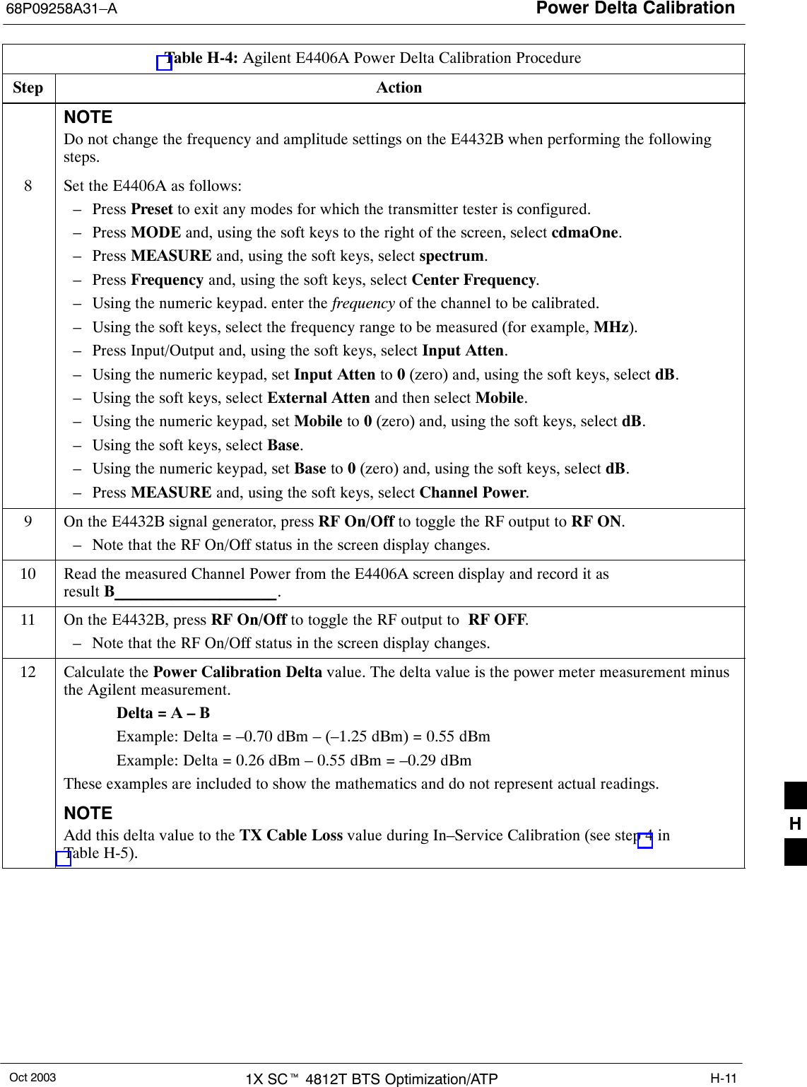
Power Delta Calibration68P09258A31–AOct 2003 1X SCt 4812T BTS Optimization/ATP H-11Table H-4: Agilent E4406A Power Delta Calibration ProcedureStep ActionNOTEDo not change the frequency and amplitude settings on the E4432B when performing the followingsteps.8Set the E4406A as follows:– Press Preset to exit any modes for which the transmitter tester is configured.– Press MODE and, using the soft keys to the right of the screen, select cdmaOne.– Press MEASURE and, using the soft keys, select spectrum.– Press Frequency and, using the soft keys, select Center Frequency.– Using the numeric keypad. enter the frequency of the channel to be calibrated.– Using the soft keys, select the frequency range to be measured (for example, MHz).– Press Input/Output and, using the soft keys, select Input Atten.– Using the numeric keypad, set Input Atten to 0 (zero) and, using the soft keys, select dB.– Using the soft keys, select External Atten and then select Mobile.– Using the numeric keypad, set Mobile to 0 (zero) and, using the soft keys, select dB.– Using the soft keys, select Base.– Using the numeric keypad, set Base to 0 (zero) and, using the soft keys, select dB.– Press MEASURE and, using the soft keys, select Channel Power.9On the E4432B signal generator, press RF On/Off to toggle the RF output to RF ON.– Note that the RF On/Off status in the screen display changes.10 Read the measured Channel Power from the E4406A screen display and record it as result B____________________.11 On the E4432B, press RF On/Off to toggle the RF output to  RF OFF.– Note that the RF On/Off status in the screen display changes.12 Calculate the Power Calibration Delta value. The delta value is the power meter measurement minusthe Agilent measurement.Delta = A – BExample: Delta = –0.70 dBm – (–1.25 dBm) = 0.55 dBmExample: Delta = 0.26 dBm – 0.55 dBm = –0.29 dBmThese examples are included to show the mathematics and do not represent actual readings.NOTEAdd this delta value to the TX Cable Loss value during In–Service Calibration (see step 4 inTable H-5). H
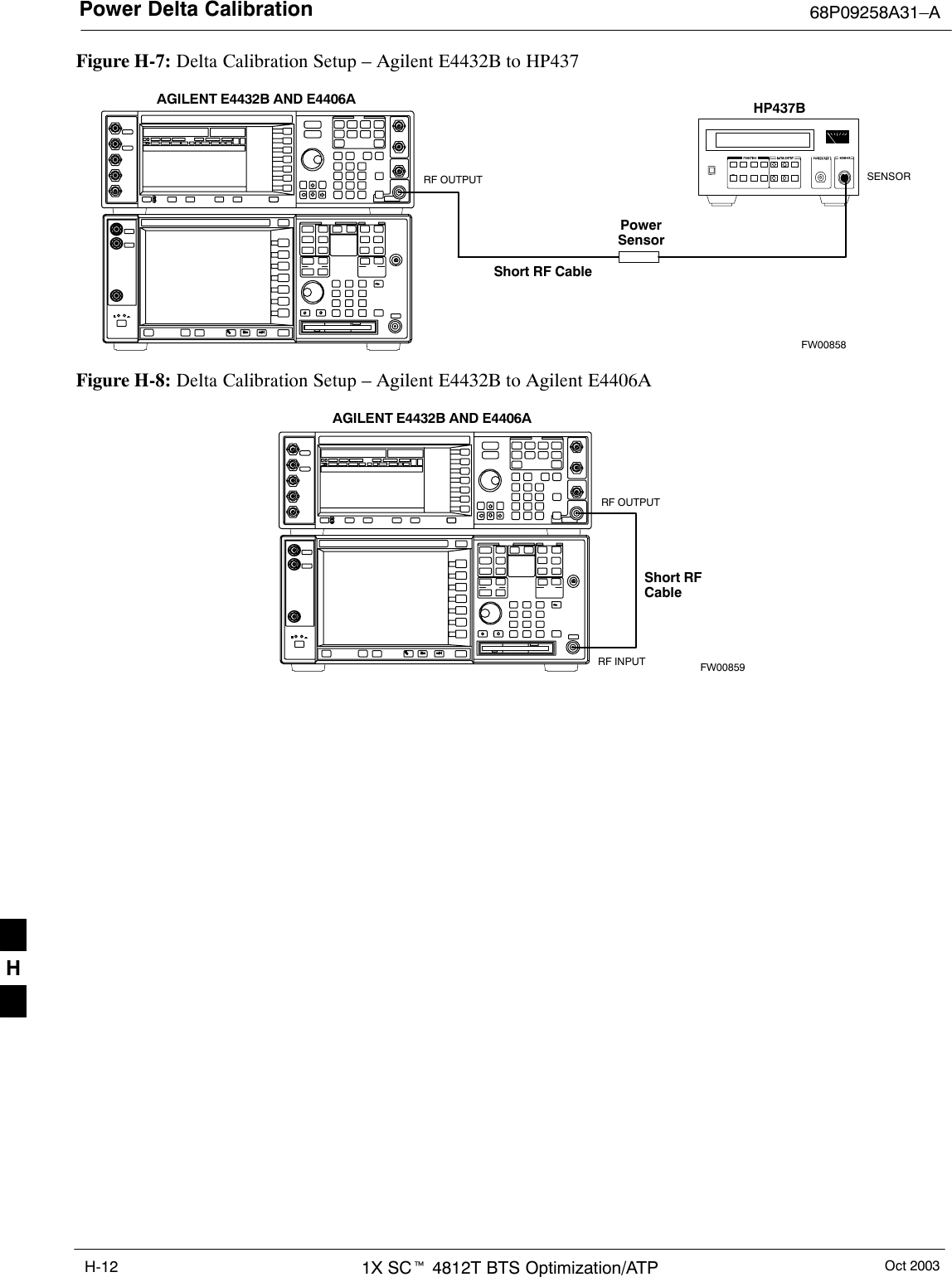
Power Delta Calibration 68P09258A31–AOct 20031X SCt 4812T BTS Optimization/ATPH-12Figure H-7: Delta Calibration Setup – Agilent E4432B to HP437PowerSensorAGILENT E4432B AND E4406AShort RF CableHP437BSENSORRF OUTPUTFW00858Figure H-8: Delta Calibration Setup – Agilent E4432B to Agilent E4406AShort RFCableRF INPUTAGILENT E4432B AND E4406ARF OUTPUTFW00859H
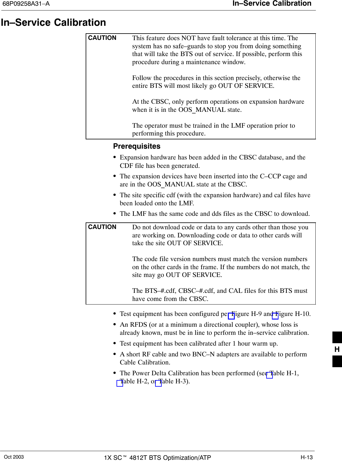
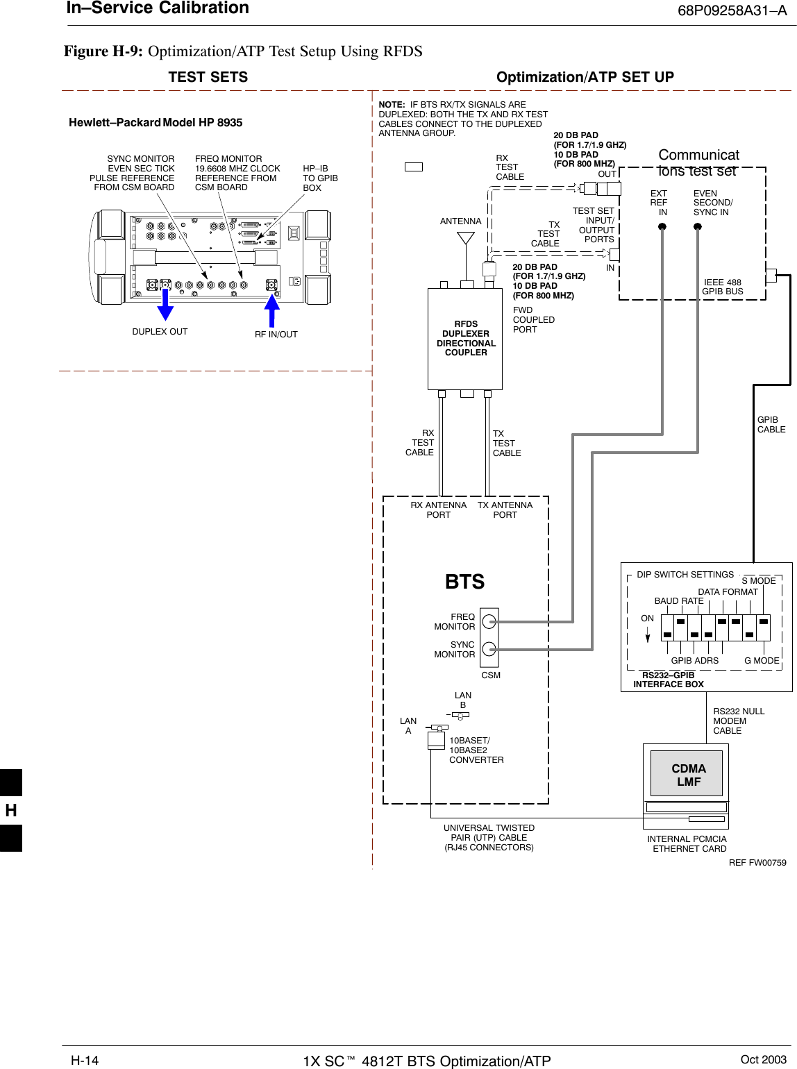
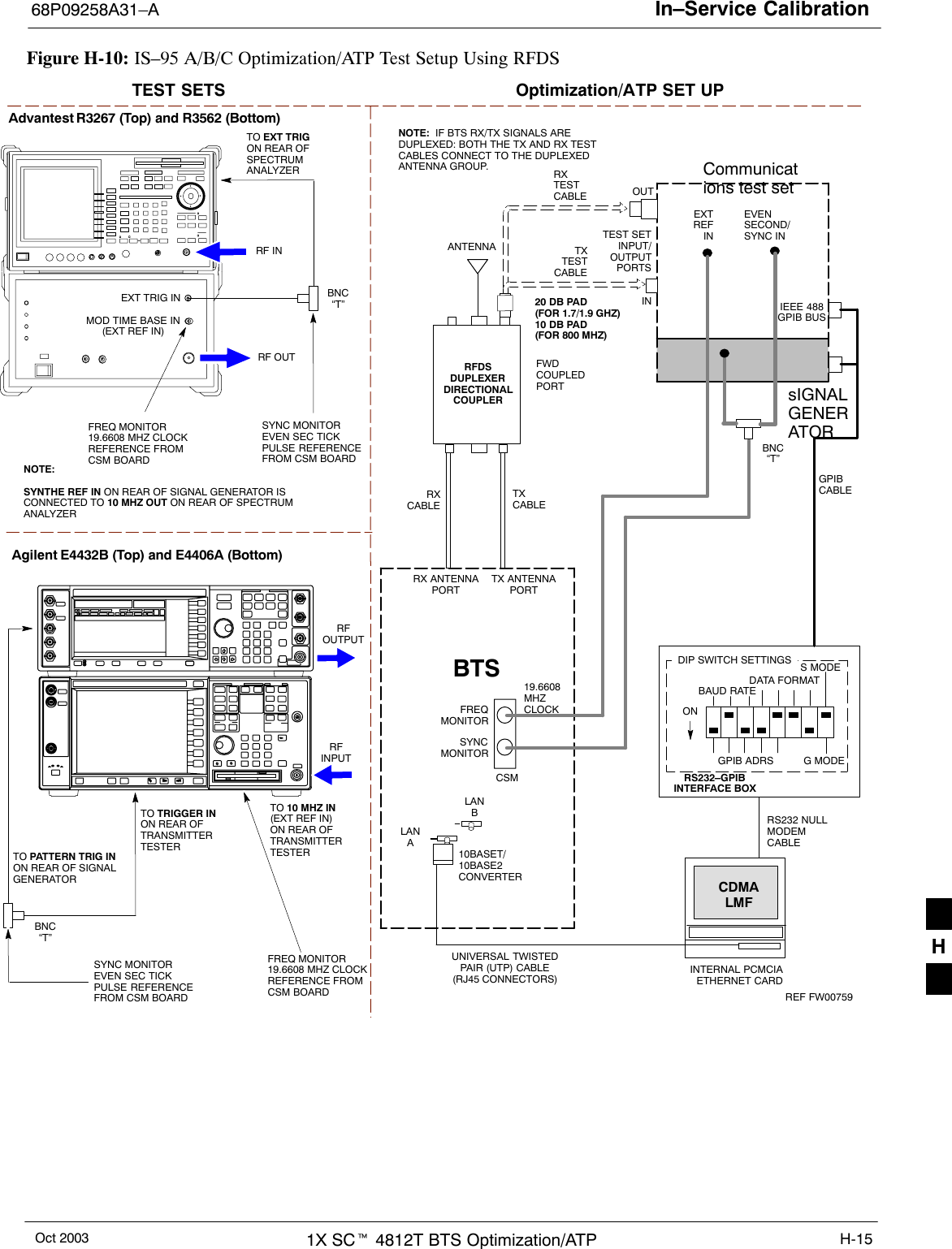
In–Service Calibration68P09258A31–AOct 2003 1X SCt 4812T BTS Optimization/ATP H-13In–Service CalibrationCAUTION This feature does NOT have fault tolerance at this time. Thesystem has no safe–guards to stop you from doing somethingthat will take the BTS out of service. If possible, perform thisprocedure during a maintenance window.Follow the procedures in this section precisely, otherwise theentire BTS will most likely go OUT OF SERVICE.At the CBSC, only perform operations on expansion hardwarewhen it is in the OOS_MANUAL state.The operator must be trained in the LMF operation prior toperforming this procedure.PrerequisitesSExpansion hardware has been added in the CBSC database, and theCDF file has been generated.SThe expansion devices have been inserted into the C–CCP cage andare in the OOS_MANUAL state at the CBSC.SThe site specific cdf (with the expansion hardware) and cal files havebeen loaded onto the LMF.SThe LMF has the same code and dds files as the CBSC to download.CAUTION Do not download code or data to any cards other than those youare working on. Downloading code or data to other cards willtake the site OUT OF SERVICE.The code file version numbers must match the version numberson the other cards in the frame. If the numbers do not match, thesite may go OUT OF SERVICE.The BTS–#.cdf, CBSC–#.cdf, and CAL files for this BTS musthave come from the CBSC.STest equipment has been configured per Figure H-9 and Figure H-10.SAn RFDS (or at a minimum a directional coupler), whose loss isalready known, must be in line to perform the in–service calibration.STest equipment has been calibrated after 1 hour warm up.SA short RF cable and two BNC–N adapters are available to performCable Calibration.SThe Power Delta Calibration has been performed (see Table H-1,Table H-2, or Table H-3).H
In–Service Calibration 68P09258A31–AOct 20031X SCt 4812T BTS Optimization/ATPH-14Figure H-9: Optimization/ATP Test Setup Using RFDSTXTESTCABLEHewlett–Packard Model HP 8935DUPLEX OUTTEST SETS Optimization/ATP SET UPRF IN/OUTHP–IBTO GPIBBOXRX ANTENNAPORTTX ANTENNAPORTRS232–GPIBINTERFACE BOXINTERNAL PCMCIAETHERNET CARDGPIBCABLEUNIVERSAL TWISTEDPAIR (UTP) CABLE(RJ45 CONNECTORS)RS232 NULLMODEMCABLES MODEDATA FORMATBAUD RATEGPIB ADRS G MODEONBTSTXTESTCABLECDMALMFDIP SWITCH SETTINGS10BASET/10BASE2CONVERTERLANBLANARXTESTCABLECommunications test setIEEE 488GPIB BUSINTEST SETINPUT/OUTPUTPORTSOUTNOTE:  IF BTS RX/TX SIGNALS AREDUPLEXED: BOTH THE TX AND RX TESTCABLES CONNECT TO THE DUPLEXEDANTENNA GROUP.ANTENNARFDSDUPLEXERDIRECTIONALCOUPLEREVENSECOND/SYNC INEXTREF INFREQMONITORSYNCMONITORCSMREF FW00759SYNC MONITOREVEN SEC TICKPULSE REFERENCEFROM CSM BOARDFREQ MONITOR19.6608 MHZ CLOCKREFERENCE FROMCSM BOARDRXTESTCABLEFWDCOUPLEDPORT20 DB PAD(FOR 1.7/1.9 GHZ)10 DB PAD(FOR 800 MHZ)20 DB PAD(FOR 1.7/1.9 GHZ)10 DB PAD(FOR 800 MHZ)H
In–Service Calibration68P09258A31–AOct 2003 1X SCt 4812T BTS Optimization/ATP H-15Figure H-10: IS–95 A/B/C Optimization/ATP Test Setup Using RFDSTEST SETS Optimization/ATP SET UPRFINPUTRFOUTPUTAgilent E4432B (Top) and E4406A (Bottom)FREQ MONITOR19.6608 MHZ CLOCKREFERENCE FROMCSM BOARDSYNC MONITOREVEN SEC TICKPULSE REFERENCEFROM CSM BOARDBNC“T”TO TRIGGER INON REAR OFTRANSMITTERTESTERTO PATTERN TRIG INON REAR OF SIGNALGENERATORTO 10 MHZ IN(EXT REF IN) ON REAR OFTRANSMITTERTESTER RF INRF OUTAdvantest R3267 (Top) and R3562 (Bottom)FREQ MONITOR19.6608 MHZ CLOCKREFERENCE FROMCSM BOARDSYNC MONITOREVEN SEC TICKPULSE REFERENCEFROM CSM BOARDBNC“T”NOTE:SYNTHE REF IN ON REAR OF SIGNAL GENERATOR ISCONNECTED TO 10 MHZ OUT ON REAR OF SPECTRUMANALYZERTO EXT TRIG ON REAR OFSPECTRUMANALYZERTXTESTCABLERX ANTENNAPORTTX ANTENNAPORTRS232–GPIBINTERFACE BOXINTERNAL PCMCIAETHERNET CARDGPIBCABLEUNIVERSAL TWISTEDPAIR (UTP) CABLE(RJ45 CONNECTORS)RS232 NULLMODEMCABLES MODEDATA FORMATBAUD RATEGPIB ADRS G MODEONBTSTXCABLECDMALMFDIP SWITCH SETTINGS10BASET/10BASE2CONVERTERLANBLANARXTESTCABLECommunications test setIEEE 488GPIB BUSINTEST SETINPUT/OUTPUTPORTSOUTNOTE:  IF BTS RX/TX SIGNALS AREDUPLEXED: BOTH THE TX AND RX TESTCABLES CONNECT TO THE DUPLEXEDANTENNA GROUP.ANTENNARFDSDUPLEXERDIRECTIONALCOUPLEREVENSECOND/SYNC INEXTREF INFREQMONITORSYNCMONITORCSMREF FW00759RXCABLEFWDCOUPLEDPORT sIGNALGENERATOREXT TRIG INMOD TIME BASE IN(EXT REF IN)19.6608MHZCLOCKBNC“T”20 DB PAD(FOR 1.7/1.9 GHZ)10 DB PAD(FOR 800 MHZ)H
In–Service Calibration 68P09258A31–AOct 20031X SCt 4812T BTS Optimization/ATPH-16Follow the procedure in Table H-5 to perform the In–ServiceCalibration.Table H-5: In–Service CalibrationStep ActionNOTEPerform this procedure after test equipment has been allowed to warm–up and stabilize for a minimumof 60 minutes.1Set up the LMF for In–Service Calibration:– Start the LMF by double–clicking the LMF icon on the Windows desktop.– Click Tools>Options from the menu bar at the login screen.– Check the applicable spectrum analyzer check box and the signal generator check box on the TestEquipment tab.Ensure that the GPIB address is 18 for the CDMA analyzer and 1 for the signal generator.– Uncheck any other other equipment that is selected.– Click the Apply button.– Select the BTS Options tab in the LMF Option window.– Check the In–Service Calibration check box.– Click the Apply button.– Click the Dismiss button to close the LMF Option window.2Login to the target BTS:– Select the target BTS icon.– Click the Login button at the login screen.3Measure the Cable Loss using the Cable Calibration function:– Click Util>Cable Calibration from the menu bar at the main window.– Set the desired channel(s) and select TX and RX CABLE CAL at the cable calibration pop upwindow.– Click the OK button to perform cable calibration.– Follow the on–screen instructions to complete the cable loss measurement.NOTE– The measured value is input automatically to the cable loss file.– To view the cable loss file, click Util>Examine>Cable Loss>TX or RX.4Add the spectrum analyzer power delta to the Cable Loss.– To view the cable loss file, click Util>Examine>Cable Loss>TX or RX.– Add the value computed in Table H-1, Table H-2, or Table H-3 to the TX Cable Loss.NOTEBe sure to include the sign of the value. The following examples are included to show the mathematicsand do not represent actual readings:– Example: 5.65 dBm + 0.55 dBm = 6.20 dBm– Example: 5.65 dBm + (–0.29 dBm) = 5.36 dBm– Example: –5.65 dBm + 0.55 dBm = –5.10 dBm– Example: –5.65 dBm + (–0.29 dBm) = –5.94 dBm. . . continued on next pageH
In–Service Calibration68P09258A31–AOct 2003 1X SCt 4812T BTS Optimization/ATP H-17Table H-5: In–Service CalibrationStep Action5Input the Coupler Loss for the TX and RX tests:– Click Util>Edit>Coupler Loss>TX or RX from the menu bar at the main window.– Input the appropriate coupler loss for the target carrier(s) by referring to the information taken atthe time of BTS installation.– Click the Save button.– Click the Dismiss button to close the window.– To view the coupler loss file, click Util>Examine>Coupler Loss>TX or RX.6Have the CBSC operator put the redundant BBX OOS_MANUAL.! CAUTIONBe sure to download OOS devices only. Loading in–service devices takes them OUT OF SERVICEand can result in dropped calls.The code file version numbers must match the version numbers on the other cards in the frame. If thenumbers do not match, the site may go OUT OF SERVICE.NOTEBe sure to include the redundant BBX in steps 7, 8, and 9.7Download code and data to the target devices:– Click Tools>Update NextLoad>CDMA to set the code version that will be downloaded.– Select the BTS(s) you need, check the appropriate code version in the pop up window, and clickthe Save button to close.– Select the target BBX(s) on the C–CCP cage picture.– Click Device>Download>Code/Data to start downloading code.– Select the target BBX(s) on the C–CCP cage picture.– Click Device>Download>Data to start downloading data.. . . continued on next pageH
In–Service Calibration 68P09258A31–AOct 20031X SCt 4812T BTS Optimization/ATPH-18Table H-5: In–Service CalibrationStep Action! CAUTIONPerform the In–service Calibration procedure on OOS devices only.8Select the desired test:– Select the target BBX(s) on the C–CCP cage picture.– Click Tests>[desired test] from the menu bar at the main window.– Select the target carrier and confirm the channel number in the pop up window.– Leave the Verify BLO check box checked.– From the Test Pattern pick list, select a test pattern.– Click the OK button to start calibration.– Follow the on–screen instructions, except, do not connect to the BTS antenna port, connect to thedirectional coupler (fwd) port associated with the on screen prompt antenna port.NOTESSelecting Pilot (default) performs tests using a pilot signal only.SSelecting Standard performs tests using pilot, synch, paging and six traffic channels. This requiresan MCC to be selected.SSelecting CDFPilot performs tests using a pilot signal, however, the gain for the channel elementsis specified in the CDF file.SSelecting CDF performs tests using pilot, synch, paging and six traffic channels, however, the gainfor the channel elements is specified in the CDF file.9Save the result and download the BLO data to the target BBX(s):– Click the Save Result button on the result screen.The window closes automatically.10 Logout from the BTS and close the LMF session:– Click BTS>Logout to close the BTS connection.– Close the LMF window.11 Restore the new “bts–*.cal” file to the CBSC.12 Enable the target device(s) from the CBSC. H
Oct 2003 1X SCt 4812T BTS Optimization/ATP I-1Appendix IVSWRI
Transmit & Receive Antenna VSWR 68P09258A31–AOct 20031X SCt 4812T BTS Optimization/ATPI-2Transmit & Receive Antenna VSWRPurposeThe following procedures will verify that the Voltage Standing WaveRatio (VSWR) of all antennas and associated feed lines fall withinacceptable limits. The tests will be performed on all antennas in asequential manner (i.e., ANT 1, then ANT 2) until all antennas/feedlineshave been verified.These procedures should be performed periodically by measuring eachrespective antenna’s VSWR (reflected power) to verify that the antennasystem is within acceptable limits. This will ensure continued peaksystem performance.The antenna VSWR will be calculated at the CDMA carrier frequencyassigned to each antenna. Record and verify that they meet the testspecification of less than or equal to 1.5:1.NOTE Motorola  recommends that the installer be familiar with thefollowing procedure in its entirety before beginning the actualprocedure. Ensure that the entire site is currently not in service.This test is used to test RX antennas by substituting RXfrequencies for TX frequencies.Study the site engineering documents and perform the following testsonly after first verifying that the RF cabling configuration required tointerconnect the BTS frames and antennas meet requirements called outin the BTS Installation Manual.Test equipmentThe following pieces of test equipment will be required to perform thistest:SLMFSDirectional couplerSCommunications test setWARNING Prior to performing antenna tests, insure that no CDMA BBXchannels are keyed. Failure to do so could result in personalinjury or serious equipment damage.I
Transmit & Receive Antenna VSWR68P09258A31–AOct 2003 1X SCt 4812T BTS Optimization/ATP I-3Equipment Setup – HP Test Set Follow the procedure in Table I-1 to set up test equipment required tomeasure and calculate the VSWR for each antenna.Table I-1: VSWR Measurement Procedure – HP Test SetStep Action HP TEST SET1If you have not already done so, refer to the procedure in Table 3-5 on page 3-17 to set up testequipment & interface the LMF computer to the BTS.2For manual VSWR testing, using external directional coupler, refer to Figure I-1 (1700/1900 MHz)or Figure I-2 (800 MHz).– Connect the communications test set RF OUT ONLY port to the INPUT port of the directionalcoupler.– Connect the RF IN/OUT port of the communication test set to the reverse (RVS) port on thedirectional coupler. Terminate the forward port with a 50 ohm load.– Install the antenna feed line to the output port on the directional coupler.NOTEManual Communications Analyzer test setup (fields not indicated remain at default):SSet screen to RF GEN.– For 1900 MHz systems, set the RF Gen Freq to center frequency of actual CDMA carrierbetween 1930–1990 MHz for TX and 1850–1910 MHz for RX. For 800 MHz systems, set theRF Gen Freq to center frequency of actual CDMA carrier between 869–894 MHz for TX and824–849 MHz for RX. For 1700 MHz systems, set the RF Gen Freq to center frequency ofactual CDMA carrier between 1840–1870 MHz for TX and 1750–1780 MHz for RX.– Set Amplitude to –30 dBm.– Set Output Port to RF OUT.– Set AFGen1 & AFGen2 to OFF.3Remove the antenna feed line and install an “RF short” onto the directional coupler output port.NOTESet–up communication test set as follows (fields not indicated remain at default):SSet  screen to SPEC ANL.– Under Controls, set input port to ANT.–Set Ref Level to –40 dBm.– Under Controls, select Main, select Auxiliary.– Under Controls, select AV G . Set Avg = 20.4– Record the reference level on the communications analyzer and Note as PS for reference. – Replace the short with the antenna feedline. Record the reference level on the communicationsanalyzer and Note for as PA reference.– Record the difference of the two readings in dB.. . . continued on next page I
Transmit & Receive Antenna VSWR 68P09258A31–AOct 20031X SCt 4812T BTS Optimization/ATPI-4Table I-1: VSWR Measurement Procedure – HP Test SetStep HP TEST SETAction5Calculate the VSWR per the equation shown to the right.Where:RL(dB) =PA(dBm) – PS(dBm) PA = Power reflected from antennaPS = Power reflected from shortA calculated value of  –13.98 dB equates to VSWR of better than 1.5:1.VSWR +ȧȧȡȢ1)10RL201–10RL20ȧȧȣȤ6If the readings indicate a potential problem, verify the physical integrity of all cables (including anyin–line components, pads, etc.) and associated connections up to the antenna. If problem still persists,consult antenna OEM documentation for additional performance verification tests or replacementinformation.7Repeat steps 2 through 6 for all remaining TX sectors/antennas.8Repeat steps 2 through 6 for all remaining RX sectors/antennas. Figure I-1: Manual VSWR Test Setup Using HP8921 Test Set (1700/1900 MHz)RF OUTONLYPORTRFIN/OUTPORTRVS(REFLECTED)PORTFEED LINE TOANTENNAUNDER TESTRF SHORT30 DBDIRECTIONALCOUPLEROUTPUTPORTFWD (INCIDENT)PORT 50–OHMTERMINATED LOADINPUTPORTFW00342I
Transmit & Receive Antenna VSWR68P09258A31–AOct 2003 1X SCt 4812T BTS Optimization/ATP I-5Figure I-2: Manual VSWR Test Setup Using HP8921 Test Set (800 MHz)FWD (INCIDENT)PORT 50–OHMTERMINATED LOADRVS(REFLECTED)PORTFEED LINE TOANTENNAUNDER TESTRF SHORT30 DBDIRECTIONALCOUPLER OUTPUTPORTINPUTPORTFW00343Equipment Setup – Advantest  Test SetFollow the steps in Table I-2 to set up test equipment required tomeasure and calculate the VSWR for each antenna.Table I-2: VSWR Measurement Procedure – Advantest Test SetStep Action ADVANTEST1If you have not already done so, refer to the procedure in Table 3-5 on page 3-17 to set up testequipment and interface the LMF computer to the BTS.2For manual VSWR testing using external directional coupler, refer to Figure I-3.– Connect the communications test set RF OUT port to the input port of the directional coupler.– Connect the INPUT port of the communication test set to the forward port on the directionalcoupler. Terminate the forward port with a 50 Ohm load.– Connect the RF short to the directional coupler output port.. . . continued on next pageI
Transmit & Receive Antenna VSWR 68P09258A31–AOct 20031X SCt 4812T BTS Optimization/ATPI-6Table I-2: VSWR Measurement Procedure – Advantest Test SetStep ADVANTESTAction3Preform the following to instruct the calibrated test set to generate a CDMA RF carrier (RVL call)with all zero longcode at the assigned RX frequency at –10 dBm:SPush the ADVANCE Measurement key.SPush the CDMA Sig CRT menu key.SPush the FREQ Entry key:– For 1900 MHz systems, set RF Gen Freq to center frequency of actual CDMA carrier between1930–1990 MHz for  TX and 1850–1910 MHz for RX.– For 800 MHz systems, set RF Gen Freq to center frequency of actual CDMA carrier between869–894 MHz for  TX and 824–849 MHz for RX.– For 1700 MHz systems, set RF Gen Freq to center frequency of actual CDMA carrier between1840–1870 MHz for  TX and 1750–1780 MHz for RX.SPush the LEVEL Entry key; set to 0 dBm (by entering 0 and pushing the –dBm key).SVerify  that ON is active in the Output CRT menu key.SVerify  that OFF is active in the Mod CRT menu key.SPush the CW Measurement key.SPush the FREQ Entry key.– Push the more 1/2 CRT menu key.– Set Preselect CRT menu key to 3.0G.SPush the Transient Measurement key.– Push the Tx Power CRT menu key.– Push the LEVEL entry key (set to 7 dBm by entering 7 and pushing the the dBm key).– Set Avg Times CRT menu key to ON. Set to 20 (by entering 20 and pushing the Hz ENTERkey).SPush the REPEAT Start key to take the measurement.4Record the Burst Power display on the communications analyzer and Note as PS for reference.5Install the antenna feedline to the output port of the directional coupler.6SPush the Auto Level Set CRT menu key.SPush the REPEAT Start key to take the measurement.7Record the Burst Power on the communications analyzer and Note as PA level for reference.Record the difference of the two readings in dBm.8Calculate the VSWR per the equation shown to the right.Where:RL(dB) =PA(dBm) – PS(dBm) PA = Power reflected from antennaPS = Power reflected from shortA calculated value of  –13.98 dB equates to VSWR of better than 1.5:1.VSWR +ȧȧȡȢ1)10RL201–10RL20ȧȧȣȤ. . . continued on next pageI
Transmit & Receive Antenna VSWR68P09258A31–AOct 2003 1X SCt 4812T BTS Optimization/ATP I-7Table I-2: VSWR Measurement Procedure – Advantest Test SetStep ADVANTESTAction9If the readings indicate a potential problem, verify the physical integrity of all cables (including anyin–line components, pads, etc.) and associated connections up to the antenna. If problem still persists,consult antenna OEM documentation for additional performance verification tests or replacementinformation.10 Repeat steps 2 through 9 for all remaining TX sectors/antennas.11 Repeat steps 2 through 9 for all remaining RX sectors/antennas. Figure I-3: Manual VSWR Test Setup Using Advantest R3465RVS(REFLECTED)PORTFEED LINE TOANTENNAUNDER TESTRF SHORT30 DBDIRECTIONALCOUPLEROUTPUTPORTFWD (INCIDENT)PORT 50–OHMTERMINATED LOADINPUTPORTRF OUTRF INFW00332I
Transmit & Receive Antenna VSWR 68P09258A31–AOct 20031X SCt 4812T BTS Optimization/ATPI-8NotesI
Oct 2003 1X SCt 4812T BTS Optimization/ATP J-1Appendix JPacket Backhaul ConfigurationJ
BTS Router Initial Configuration 68P09258A31–AOct 20031X SCt 4812T BTS Optimization/ATPJ-2BTS Router Initial ConfigurationOverviewThis appendix contains information and operations related to loading anMWR 1941 BTS router with the minimum standard (canned)configuration necessary for network communications. Once the router iscommunicating on the network, the full, site-specific, operationalconfiguration can be downloaded to the router over the network. Thisappendix includes sections on:STerminal SetupSDownloading canned BTS router configuration filesSVerifying IOS canned version of CF memory cardSReplacing installed BTS router CF memory card IOS versionSVerify and upgrade rommon versionSRecovery from BTS router boot to rommonSEntering or changing router FE interface IP addressSPreparation for site turn–overJ
Terminal Setup68P09258A31–AOct 2003 1X SCt 4812T BTS Optimization/ATP J-3Terminal SetupGeneralThis section provides the procedures to configure and save a terminalsession for communicating with the MWR 1941 BTS router. Terminalsettings are the same as those used for BTS card and moduleMan–Machine Interface (MMI) communication sessions. The proceduresare for a Pentiumr processor–based computer operating with eitherWindows 98 Second Edition (SE) or Windows 2000.Using the LMF computerLMF computer platforms can be used for communicating with therouters, and the MMI terminal connection created for BTS card/moduleoptimization actions will operate with the BTS routers. See the“Establishing a BTS Router Communication Session” section of thisappendix for additional interface hardware required for BTS routercommunication.Terminal SettingsFollow the procedure in Table J-1 to create a named HyperTerminalconnection for BTS router interface and generate a Windows desktopshortcut for it.NOTE There are differences between Windows 2000 and Windows 98 inthe menus and screens used for creating a HyperTerminalconnection. In the following procedure, items applicable to:SWindows 2000 will be identified with Win2000SWindows 98 will be identified with Win98Table J-1: Establish HyperTerminal ConnectionStep Action1From the Windows Start menu, select Programs > Accessories2Perform one of the following:SFor Win2000, select Hyperterminal and then click on HyperTerminalSFor Win98, select Communications, double click the Hyperterminal folder, and then double clickon the Hypertrm.exe icon in the window which opens.NOTESIf a Location Information Window appears, enter the required information, then click on theClose button. (This is required the first time a HyperTerminal connection is configured, even if amodem is not to be used.)SIf a You need to install a modem..... message appears, click on NO.3When the Connection Description box opens:– Type a name for the connection being defined (for example, BTSRTR Session, MMI) in theName: window,– Highlight any icon preferred for the named connection in the Icon: chooser window, and– Click  OK.. . . continued on next page J
Terminal Setup 68P09258A31–AOct 20031X SCt 4812T BTS Optimization/ATPJ-4Table J-1: Establish HyperTerminal ConnectionStep Action4From the Connect using: pick list in the Connect To box displayed, select the RS–232 port to beused for the connection (e.g., COM1 or COM2 – Win2000 or Direct to Com 1 or Direct to Com 2 –Win98), and click OK.5In the Port Settings tab of the COM# Properties window displayed, configure the RS–232 portsettings as follows:SBits per second:  9600SData bits:  8SParity:  NoneSStop bits: 1SFlow control: None6 Click OK.7With the HyperTerminal window still open and the connection running, select:File > Properties8Click the Settings tab, click the arrow in the Emulation window, and select VT100 from thedropdown list.9Click the ASCII Setup button, uncheck all boxes in the ASCII Setup window which appears, andclick OK.10 Click OK for the connection Properties box.11 Save the defined connection by selecting:File > Save12 Close the HyperTerminal window by selecting:File > Exit13 Click the Yes button to disconnect when prompted.14 Perform one of the following:SIf the Hyperterminal folder window is still open (Win98), proceed to step 16, orSFrom the Windows Start menu, select Programs > Accessories15 Perform one of the following:SFor Win2000, select Hyperterminal and release any pressed mouse buttons.SFor Win98, select Communications and double click the Hyperterminal folder.16 Highlight the newly–created connection icon by moving the cursor over it (Win2000) or clicking on it(Win98).17 Right click and drag the highlighted connection icon to the Windows desktop and release the rightmouse button.18 From the popup menu displayed, select Create Shortcut(s) Here.. . . continued on next pageJ
Terminal Setup68P09258A31–AOct 2003 1X SCt 4812T BTS Optimization/ATP J-5Table J-1: Establish HyperTerminal ConnectionStep Action19 If desired, reposition the shortcut icon for the new connection by dragging it to another location on theWindows desktop.NOTEThe shortcut icon can now be double–clicked to open a BTS router or BTS card/module MMIHyperTerminal session without the need to negotiate multiple menu levels. BTS Router Serial CommunicationFor those procedures which require serial communication with BTSrouters, follow the procedures in Table J-2 to initiate the communicationsession. This procedure calls out the LMF computer platform, but anyVT100–equivalent terminal or computer equipped with terminalemulation software and a hardware serial connector may be used.Required ItemsThe following items are required to perform the verification:SLMF computer platform or equivalent (see this manual forrequirements)SEight–conductor (four–pair, unshielded twisted pair is acceptable)rollover cable, two 8–contact modular plugs (see Figure J-1 for cablewiring requirements)SAdapter, DB–9 plug–to–8–contact modular plug, Global ComputerSupplies C4717 or equivalent (see Figure J-2 for adapter wiringrequirements)Figure J-1: Wiring Diagram, BTS Router Communication Rollover Cable8–contact PlugContact Numbering(Insertion End)1234567812345678123456788–contactModularPlug8–contactModularPlugLockingClipJ
Terminal Setup 68P09258A31–AOct 20031X SCt 4812T BTS Optimization/ATPJ-6Figure J-2: Wiring Diagram, DB–9 Plug–to–8–contact Modular Plug AdapterAdapterDB–9 Receptacle Socket Numbering(Mating Side)Adapter8–contact  ReceptacleContact Numbering(Mating Side)1234567891234567812345678912345678NCNCDB–9Receptacle8–contactModularReceptacleTable J-2: Establishing BTS Router Serial CommunicationStep Action1If it has not been done, start the computer and allow it to complete boot–up.2If a named HyperTerminal connection for BTS router serial communication or BTS card/module MMIcommunication has not been created on the LMF computer, create one as described in Table J-1 in the“Terminal Set–up” section of this appendix.3Connect the computer to the BTS router as shown in Figure J-3.4Start the named HyperTerminal connection for BTS router communication sessions by double clickingon its Windows desktop shortcut.NOTEIf a Windows desktop shortcut was not created for the communication session, access the connectionfrom the Windows Start menu by selecting:Programs > Accessories > Hyperterminal > HyperTerminal > <Named HyperTerminalConnection (for example, BTSRTR)>5Once the connection window opens, establish communication with the BTS router by pressing thecomputer Enter key until the prompt identified in the applicable procedure is obtained. J
Terminal Setup68P09258A31–AOct 2003 1X SCt 4812T BTS Optimization/ATP J-7Figure J-3: LMF Computer  Connections to BTS RouterTo BTS routerCONSOLEreceptacleCOM1ORCOM2LMF COMPUTEROR EQUIVALENTOPTOATP0001–0ROLLOVERCABLEDB9–TO–RJ48CADAPTERJ
Downloading Minimum Canned BTS Router Configuration Files 68P09258A31–AOct 20031X SCt 4812T BTS Optimization/ATPJ-8Downloading Minimum Canned BTS Router Configuration FilesDownloading OverviewAfter they are generated on the OMC–R, the BTS router cannedconfiguration files must be transferred to another computer platformfrom which they can be installed into the BTS routers. A number ofprocedures may be used to move the canned configuration files from theOMC–R to a platform from which they can be loaded into the routers.Some alternatives are:1. If a floppy diskette drive is available at the OMC–R, such as the onefor UNO workstations, the configuration files can be transferred toan LMF computer or similar machine using the CDF file transferprocedure in the Preparing the LMF section of this manual.Directories identified in Table J-3 must be used rather than those inthe CDF file transfer procedure.2. If a Windows–based server connection is available in the operator’snetwork and it can provide an FTP or telnet connection to theOMC–R, files may be transferred by either the FTP or telnetmethods.3. If a dial–up connection is available for accessing the OMC–R, anFTP or telnet session may be possible to transfer files to thecomputer used to load the CF memory cards.The procedure provided in this section covers FTP transfer using aWindows–based server in the operator’s network. Coordinate with thelocal network administrator to determine the method and procedure touse on a specific network.PrerequisitesThe following must be obtained from the local network administratorbefore performing the canned configuration file FTP procedure inTable J-3:SUser ID and password to log onto the OMC–RSName of the sub–directory where the specific BTS router groupcanned configuration files to be downloaded were createdFTP File Transfer from the OMC–RThis procedure uses the Windows–based LMF computer platform todownload BTS router canned configuration files from the OMC–R.Follow the procedure in Table J-3.Table J-3: BTS Router Canned Configuration File FTP Transfer from the OMC–RStep Action1If it has not been done, create a directory on the LMF computer where the BTS router cannedconfiguration files will be stored.2If it has not been done, obtain the OMC–R logon user ID and password from the local networkadministrator.. . . continued on next pageJ
Downloading Minimum Canned BTS Router Configuration Files68P09258A31–AOct 2003 1X SCt 4812T BTS Optimization/ATP J-9Table J-3: BTS Router Canned Configuration File FTP Transfer from the OMC–RStep Action3Connect the LMF computer to the local network and log on.NOTEThis procedure uses the command line FTP client supplied with Windows 98, Second Edition (Win98SE) and Windows 2000 (Win2K); however, any commercially available FTP client application can beused. Follow the manufacturer’s instructions for operation of an alternative application.4Open a command line (MS DOS) window by clicking on Start > Programs > Command Prompt.5When the command line window opens, change to the directory where the canned configuration fileswill be stored on the LMF computer by entering:cd  pathnameWhere pathname  =  the path to the required directory.A response similar to the following will be displayed:C:\> cd Can_CfgC:\Can_Cfg>6Check the contents of the directory by entering the following:dirA response similar to the following will be displayed:C:\Can_Cfg>dir Volume in drive C is MAIN Volume Serial Number is F2AA–1721 Directory of C:\Can_Cfg>08/22/2002  03:46p      <DIR>          .08/22/2002  03:46p      <DIR>          ..08/22/2002  03:46p               2,223 btsrtr_canned.blue08/22/2002  03:47p               2,223 btsrtr_canned.red               2 File(s)          4,644 bytes               2 Dir(s)   2,556,045,312 bytes freeC:\Can_Cfg>7If either or both of the following files are found in the directory, delete them or move them to anotherdirectory:Sbtsrtr_config.blueSbtsrtr_config.red8Begin the FTP session by entering the following:ftp  hostnameWhere hostname = the OMC–R hostname or IP address.A response similar to the following will be displayed:C:\Can_Cfg> ftp OMCR–1C:\Can_Cfg>Connected to OMCR–1.220 OMCR–1 FTP server (SunOS 5.6) ready.User (OMCR–1:(none)):. . . continued on next pageJ
Downloading Minimum Canned BTS Router Configuration Files 68P09258A31–AOct 20031X SCt 4812T BTS Optimization/ATPJ-10Table J-3: BTS Router Canned Configuration File FTP Transfer from the OMC–RStep Action9Enter  the User ID and password when prompted, pressing the Enter key after each. A responsesimilar to the following will be displayed:User (OMCR–1:(none)): scadm331 Password required for scadm.Password:230 User scadm logged in.ftp>10 Change to the directory where the BTS router canned configuration file sub–directories are created andverify the present working directory by entering the following, pressing the Enter key after each:cd  /home/scadm/btsrtr_canned_configspwdA response similar to the following will be displayed:ftp> cd /home/scadm/btsrtr_canned_configs240 CWD command successful.ftp> pwd245 ”/home/scadm/btsrtr_canned_configs” is current directory.11 Enter the ls command to list the contents of the directory and be sure the specific canned configurationdirectory name provided by the administrator exists. A response similar to the following will bedisplayed:ftp> ls200 PORT command successful.150 ASCII data connection for /bin/ls (10.182.29.117,80) (0 bytes).Mon_Jul_2_01:55:07_CDT_2002Wed_Jul_24_09:35:41_CDT_2002Tue_Aug_04_10:35:22_CDT_2002226 ASCII Transfer complete.ftp: 30 bytes received in 0.02Seconds 1.50Kbytes/sec.ftp>NOTEDirectory names where canned configuration files are located will consist of theweekday_month_day_time_year when the canned configuration files were created on the OMC–R.12 Change to the directory specified for the BTS router group to be configured and list the directorycontents by entering the following, pressing the Enter key after each command:cd  weekday_month_day_time_yearlsA response similar to the following will be displayed:ftp> cd Wed_Jul_24_09:35:41_CDT_2002250 CWD command successful.ftp> ls200 PORT command successful.150 ASCII data connection for /bin/ls (10.182.29.117,80) (0 bytes).btsrtr_canned.bluebtsrtr_canned.red226 ASCII Transfer complete.ftp: 39 bytes received in 0.05Seconds 0.78Kbytes/sec.ftp>. . . continued on next pageJ
Downloading Minimum Canned BTS Router Configuration Files68P09258A31–AOct 2003 1X SCt 4812T BTS Optimization/ATP J-11Table J-3: BTS Router Canned Configuration File FTP Transfer from the OMC–RStep Action13 Change to the binary transfer mode and, if desired, turn on hash mark printing for transfer progress byentering the following, pressing the Enter key after each command:binhashA response similar to the following will be displayed:ftp> bin200 Type set to I.ftp> hashHash mark printing On  ftp: (2048 bytes/hash mark) .ftp>NOTEWith Win98 SE, turning on hash mark printing can slow down file transfer in certain circumstances,but the canned configuration files are quite small (approximately 2.5 KB) so there should be littlenoticeable effect.14 Download the BTS router canned configuration files to the LMF computer by performing the following:14a – Enter the following to download the first canned configuration file:get  btsrtr_canned.blueA response similar to the following will be displayed:ftp> get btsrtr_canned.blue200 PORT command successful.150 Binary data connection for btsrtr_canned.blue (10.182.29.117,80) (2223 bytes).#226 Binary Transfer complete.ftp: 2223 bytes received in 0.59Seconds 3.76Kbytes/sec.ftp>14b – Enter the following to download the second BTS router canned configuration file:get  btsrtr_canned.redA response similar to the following will be displayed:ftp> get btsrtr_canned.red200 PORT command successful.150 Binary data connection for btsrtr_canned.red (10.182.29.117,80) (2223 bytes).#226 Binary Transfer complete.ftp: 2223 bytes received in 0.59Seconds 3.76Kbytes/sec.ftp>. . . continued on next pageJ
Downloading Minimum Canned BTS Router Configuration Files 68P09258A31–AOct 20031X SCt 4812T BTS Optimization/ATPJ-12Table J-3: BTS Router Canned Configuration File FTP Transfer from the OMC–RStep Action15 Before terminating the FTP session, open Windows Explorer and view the contents of the directorywhere the canned configuration files are to be stored to be sure the files are present. Perform thefollowing:15a – Click Start > Programs > Windows Explorer.15b – In the left–hand pane of Windows Explorer, perform one of the following depending on the LMFcomputer operating system:–– Win98 SE: If necessary, expand the directory display for the drive where the canned configu-ration file storage directory is located by clicking on the  +  next to the drive icon.–– Win2K: Expand the user profile and directory display for the drive where the canned configu-ration file storage directory is located by clicking on the  +  next to each icon, respectively.15c – Expand any sub–directories as required to display the directory folder where the cannedconfiguration files are to be stored.15d – Click on  the directory folder icon where the canned configuration files are to be stored.15e – In the right–hand  pane, verify that the files btsrtr_canned.blue and btsrtr_canned.redappear.15f – If the files appear, proceed to step 16.15g – If the files do not appear, repeat step 14, its sub–steps, step 15 and its sub–steps.16 Close Windows Explorer, and, in the command line window, enter the bye command to terminate theFTP session. A response similar to the following will be displayed:ftp> bye221 Goodbye.C:\Can_Cfg>17 Close the command line window by entering the  exit command.18 BTS router canned configuration files are now ready for transfer to a BTS router. J
Verifying IOS Canned Version of the CF Memory Card68P09258A31–AOct 2003 1X SCt 4812T BTS Optimization/ATP J-13Verifying IOS Canned Version of the CF Memory CardOverviewThis section covers the procedures and commands required to verify theIOS version loaded on BTS router CF memory cards and copy standardcanned configuration files to the routers. Because of the set–up requiredand the length of some of the procedures, Motorola recommendsperforming the actions covered in this section at a central location toprepare the BTS routers for installation prior to the site visit.IOS Version Verification and File Sequence PositionVersion verification – The IOS version loaded on the BTS router CFmemory card should be verified as the version required for operation onthe network where the routers will be installed. If the loaded IOS versionis not correct, it can be replaced with a different version. There areseveral methods available to accomplish version verification. Thesedepend on the equipment and software applications the user selects touse in installing the canned configuration files in the BTS routers.Appropriate verification procedures are included in each of the twocanned configuration installation methods covered in this section.Methods to change the loaded IOS version are provided in the ChangeBTS Router IOS Version section of this appendix and are referenced atthe appropriate places in the canned configuration installation methods.File sequence position – During initialization, the MWR 1941 routerwill first search the startup–config file for a boot system commandline telling it in what directory and file to find the boot loader. If this lineis not found, the router will default to attempting to boot from the firstfile in its flash memory. Flash memory for the MWR 1941 is the CFmemory card (software identifier slot0:). The canned configuration filesused for BTS router installation do not contain a boot system commandline because of the need to maintain flexibility for IOS version changes.Because of this, it is critical that the IOS file is the first file listed on theCF memory card. The canned configuration installation procedurescontain steps to assure that this is the case, and, if it is not, provideguidance to correct the condition. It is important to remember that, if therouter boots and displays a rommon 1 > prompt, the IOS file ismissing, out of sequence, has a corrupted flash memory image or thestartup–config file contains a boot system line which specifies amissing or incorrect IOS pathname/filename.Canned Configuration File InstallationFilename and installation location requirements – The cannedconfiguration files for the BTS routers must be copied to the CF memorycard. The filename of the file on the CF memory card must becanned–config. Canned configuration file location and filenamerequirements are a result of Mobile Wireless Center (MWC) actionsduring the process of switching a BTS from packet to circuit mode. Inthis process, the MWC will query the BTS routers’ slot0: directory for afile named canned–config. A missing or mis–named file will causeproblems with execution of the mode–switching process. J
Verifying IOS Canned Version of the CF Memory Card 68P09258A31–AOct 20031X SCt 4812T BTS Optimization/ATPJ-14Installation Methods –  The startup–config configuration file usedby the BTS router during initialization is stored in NVRAM. This is amemory device internal to the router and is separate from the CFmemory card. To install the canned configuration file so the router willuse it during boot–up, the file must be copied into thestartup–config file in NVRAM. There are two methods available toaccomplish this:1. Using a tftp server application to copy the canned configuration filefrom the Windows–based LMF computer to the CF memory cardinstalled in a router, and then copying it to the startup–configfile in the router’s NVRAM2. Using a CF memory card reader to copy the canned configurationfile to a CF memory card, and then, once the CF memory card isinstalled in the router, using a HyperTerminal communicationsession to copy the file from the CF memory card to thestartup–config file in the router’s NVRAMComparison of methods –  Preparation for using the tftp serverapplication method is extensive and requires setting up simultaneousserial and FE communication sessions with the router. This methodoffers the advantage of being able to verify IOS file sequence positionimmediately and supporting direct file transfers between the router andLMF computer without removing the CF memory card. As analternative, using a CF memory card reader to copy the cannedconfiguration file to a CF memory card, and from there to thestartup–config file requires very little set–up. With this method, theIOS file sequence position can only be verified once the CF memorycard is installed in the router, and any file transfers between the routerand LMF computer require physically moving the CF memory cardbetween the router and card reader.Procedures to use each method – Using the tftp server application tocopy the canned configuration file to a CF memory card is covered in theMethod 1 subsection. Performing the transfer process with a card readeris covered in the Method 2 subsection. The applicable procedures forverifying the loaded IOS version and file sequence position are includedin each method.File operations using a CF memory card reader – Only file transfersshould be performed using the CF memory card reader. CF memory cardformatting should be performed in a BTS router using a HyperTerminalconnection. Attempting to format a CF memory card from aWindows–based computer using a card reader could result inunpredictable BTS router operation.CAUTION Do not format BTS router CF memory cards using aWindows–based computer. Only format CF memory cards in aBTS router.J
Verifying IOS Canned Version of the CF Memory Card68P09258A31–AOct 2003 1X SCt 4812T BTS Optimization/ATP J-15Method 1: Using a TFTP Server to Load to CF Memory CardRequired Equipment and SoftwareThe following items are required to perform this procedure:SA Windows–based computer which meets the requirements of theLMF computer platform as specified in this manual.SOne of the following operating systems for the Windows–basedcomputer:–Windows 2000–Windows 98 Second Edition (SE) using the FAT32 file systemCAUTION BTS router CF memory cards loaded using computers equippedwith Windows 98 versions earlier than Windows 98 SE and usingthe FAT16 file system will not operate properly, resulting in acomplete site outage.SOne of the following for the Windows–based computer:– Internal 10/100baseT Network Interface Card (NIC)– PCMCIA 10/100baseT NICSCable, Ethernet crossover, Category 5E or better, unshielded twistedpair, two 8–contact modular plugs, in one of the following lengths, asdetermined necessary:– 0.3 m (11.8 in) (Motorola pn 3088643C07)– 0.6 m (23.6 in)(Motorola pn 3088643C13)– 1.0 m (39.4 in) (Motorola pn 3088643C15)– 2.1 m (84 in) (Motorola pn 3088643C08)– 3.0 m (120 in) (Motorola pn 3088643C09)SCable, rollover, as described in the Establishing a BTS RouterCommunication Session section of this AppendixSDB–9 plug–to–8–contact modular plug adapter as described in theEstablishing a BTS Router Communication Session section of thisAppendixSA tftp server software application (refer to the Setting Up the TFTPServer – Procedure in Cellular System Administration – CDMAOnLine Documentation) such as:– Cisco tftp server– PumpKIN tftp server– Any other equivalent tftp server applicationSA copy of the MWR 1941 router IOS version required for the networkwhere the routers are to be installed (contact the network administratoror the Motorola account team for information on obtaining therequired MWR 1941 IOS version)SA +27 Vdc power supply to power the BTS router duringconfiguration file operationsRequired MaterialsThe following material is required to perform this method:SMarking material to identify the BTS router and CF memory card withthe installed configuration (blue or red) J
Verifying IOS Canned Version of the CF Memory Card 68P09258A31–AOct 20031X SCt 4812T BTS Optimization/ATPJ-16Required PublicationsThe following publications are required to perform procedures in thissection:Sthis manualSCellular System Administration – CDMA OnLine DocumentationSMWR1941 Wireless Mobile Edge Router Software ConfigurationGuide; part number 78–13983–01Preparation for Canned Configuration File TFTPTransfer to CF Memory CardPreparation for a canned configuration file tftp transfer consists of thefollowing activities:1. Setting the LMF computer NIC IP address2. Creating a directory (folder) on the LMF computer to be used for alltftp file transfers3. Installing the tftp server application on the LMF computer, andsetting the tftp server application root directory to the directorycreated in 2, above4. Connecting the LMF computer to the BTS router for bothHyperTerminal (serial) and Ethernet communication5. BTS router power–up and initial configuration for EthernetcommunicationThe following procedures are used to accomplish all of these preparatoryactions.Set LMF computer NIC TCP/IP address and create the defaultTFTP directory – Follow the procedure in Table J-4 to set the NIC IPaddress.NOTE IMPORTANT! If the IP address for the LAN connection on anLMF computer is being changed to support tftp downloads to aBTS router, the BTS 10base–2 LAN IP address and subnet maskfor the NIC must be restored before the LMF can log into a BTSto perform an optimization or ATP.NOTE There are differences between Windows 2000 and Windows 98 inthe menus and screens used for setting or changing a NICconnection. In the following procedure, items applicableto:Windows 2000 will be identified with Win2000Windows 98will be identified with Win98J
Verifying IOS Canned Version of the CF Memory Card68P09258A31–AOct 2003 1X SCt 4812T BTS Optimization/ATP J-17Table J-4: Set LMF Computer NIC IP Address and Create a Default TFTP DirectoryStep Action1Start the computer.2Login and allow the computer to boot to the desktop.3Depending on the installed operating system, from the Windows Start menu, select one of thefollowing:SWin2000: Settings > Network and Dial–up ConnectionsSWin98: Settings > Control Panel and double–click  Network.4Perform one of the following as applicable for the installed operating system:SFor Win2000, in the list of displayed connections, locate the Local Area Network connection for theNIC to be used for BTS router Ethernet communication.SFor Win98, in the Configuration tab of the Network dialog box, locate the TCP/IP connection forthe installed NIC.– If TCP/IP does not appear in the displayed list of installed network components, refer to theoperating system documentation and install TCP/IP.5Perform one of the following as applicable for the installed operating system:SFor Win2000,  highlight the connection for the NIC and right click the highlighted connection, andselect Properties from the pop–up menu.SFor Win98:– Highlight the TCP/IP NIC connection in the displayed list of installed network components.– Click the Properties button.– Skip to step 8.6 For Win2000 , in the Local Area Connection Properties dialog box which appears, if InternetProtocol (TCP/IP) is not showing in the Components checked are used by this connection: listbox,refer to the operating system documentation and install TCP/IP.7 For Win2000, if the checkbox next to the Internet Protocol (TCP/IP) entry is not checked, click in thebox to check it.8Perform one of the following:SWin2000: Highlight the Internet Protocol (TCP/IP) entry, and click on the Properties button belowthe Components checked are used by this connection: listbox.SWin98: From the tabs displayed in the TCP/IP Properties dialog box which opens, select the IPAddress tab if it is not at the front.. . . continued on next pageJ
Verifying IOS Canned Version of the CF Memory Card 68P09258A31–AOct 20031X SCt 4812T BTS Optimization/ATPJ-18Table J-4: Set LMF Computer NIC IP Address and Create a Default TFTP DirectoryStep Action9In the Internet Protocol (TCP/IP) Properties dialog box which appears (Win2000) or the IP Addresstab of the TCP/IP Properties dialog box (Win98), perform the following:9a – If a black dot is not showing in the the radio button circle next to Use the following IP address:(Win2000) or Specify an IP address (Win98), click on the radio button.–– A black dot will appear in the circle.9b – If using an LMF computer, record the IP address and subnet mask used for LMF–BTScommunication so they can be re–entered when tftp transfer activities for the BTS router arecompleted.9c – Enter 100.100.100.1 in the IP address: box.9d – Enter 255.255.255.252 in the Subnet mask: box.10 Click the OK button for the Internet Protocol (TCP/IP) Properties dialog box (Win2000) or theTCP/IP Properties box (Win98).11 Click the OK button for the Local Area Connection Properties box (Win2000) or the Network box(Win98).12 In Win98, click File > Close to close the Control Panel window.13 Click Start > Programs > Windows Explorer to open Windows Explorer.14 If the default tftp directory will be the same directory in which the files downloaded from the OMC–Rare stored, proceed to step 22.15 In the left–hand pane of Windows Explorer, locate the icon for the drive where the default tftpdirectory is to be created.16 Highlight the drive icon and click Files > New > Folder.17 While observing the new folder icon in the right–hand pane, type the name for the folder (for example,tftp_files), and press the Enter key.18 In Windows Explorer, locate the directory where the canned configuration files downloaded from theOMC–R are stored.19 In the left–hand pane, highlight the directory where the files are stored.20 Scroll the  left–hand pane until the newly–created default tftp directory is visible.21 In the right–hand pane, highlight the canned configuration files and drag them to the default tftpdirectory.22 In the left–hand pane, click on the default tftp directory, and verify that the canned configuration filesappear in the right–hand pane.23 Load a copy of the required BTS router IOS version into the default tftp directory using FTP, internetdownload, or media such as a Zip disk (file size is over 7 MB).24 Click Files > Close to close Windows Explorer. J
Verifying IOS Canned Version of the CF Memory Card68P09258A31–AOct 2003 1X SCt 4812T BTS Optimization/ATP J-19Install and configure tftp server applicationTo obtain, install, and configure the Cisco or PumpKIN tftp softwareapplications, refer to the Setting Up the TFTP Server – Procedure inCellular System Administration – CDMA OnLine Documentation Forother tftp server applications, install and configure the applicationaccording to the manufacturer’s instructions.NOTE Important: When entering the name of the tftp server rootdirectory while configuring the tftp server application, be sure touse the name of the directory identified in Table J-4, step 14, orcreated in Table J-4, step 17, above.Connect the LMF computer to the BTS routerConnect the LMF computer to the BTS router by following theprocedure in Table J-5 and referring to Figure J-4..Figure J-4:  LMF Computer TFTP Connections to BTS RouterTo BTS routerCONSOLEreceptacleCOM1ORCOM2LMF COMPUTEROR EQUIVALENTROLLOVERCABLEDB9–TO–RJ48CADAPTERBTSRTR0025ETHERNETCROSSOVERCABLE10/100BASE TNIC PORTFAST ETHERNET PORT FE 0(SOFTWARE DESIGNATION FA0/0)CONSOLEPORTJ
Verifying IOS Canned Version of the CF Memory Card 68P09258A31–AOct 20031X SCt 4812T BTS Optimization/ATPJ-20Table J-5: Connecting the LMF Computer to the BTS Router for TFTP File TransferStep Action1If the BTS router has not been connected to a power source, be sure the +27 Vdc power source is noton, and connect it to the router.2Connect the LMF computer to the BTS router as shown in Figure J-4, referring to the list of requiredequipment in this section as required.3If the LMF computer has not been started, turn it on, login, and allow it to boot to the desktop.4Refer to the procedure in Table J-2 of this appendix, and start a HyperTerminal communication sessionfor the BTS router.5Start the tftp server application as specified for the software (refer to the Setting Up the TFTP Server –Procedure in Cellular System Administration – CDMA OnLine Documentation or the manufacturer’sinstructions). BTS router power–up and initial configuration forEthernet communication Follow the procedure in Table J-6 to apply power to the router and setan initial configuration for Ethernet communication.SThe required version of the IOS is loaded on the CF memory cardSThe CF memory card is installed in the BTS routerTable J-6: BTS Router Power–up and Initial Ethernet ConfigurationStep Action* IMPORTANTThis procedure does not cover all aspects of BTS router operation and programming. Before performing thisprocedure, review BTS router initialization, operation, and programming information and procedures inMWR1941 Wireless Mobile Edge Router Software Configuration Guide; part number 78–13983–01. Have thispublication available for reference while performing this procedure.1Be sure a CF memory card loaded with the Cisco IOS is installed in the BTS router (refer to the BTS RouterCard and Module Replacement section of the 1X SC 4812T BTS FRU Guide  68P09258A64  for instructionsto access the CF memory card slot).2* IMPORTANTIn this step do not touch the computer keyboard until the router completes the boot process. The routerwill buffer any keystrokes made during the boot process and interpret them as commands to beexecuted immediately following boot completion.Apply power to the router and allow it to complete boot–up.3If a message similar to the following, is displayed, press the Enter key and proceed to step 5:Press RETURN to get started!. . . continued on next pageJ
Verifying IOS Canned Version of the CF Memory Card68P09258A31–AOct 2003 1X SCt 4812T BTS Optimization/ATP J-21Table J-6: BTS Router Power–up and Initial Ethernet ConfigurationStep Action4If a message similar to the following, is displayed type no and press the Enter key:Basic management setup configures only enough connectivityfor management of the system, extended setup will ask youto configure each interface on the systemWould you like to enter basic management setup? [yes/no]:A response similar to the following will be displayed:Would you like to enter basic management setup? [yes/no]: noCisco Internetwork Operating System SoftwareIOS (tm) 1941 Software (MWR1941–I–M), Version 12.2(20020127:101239Copyright (c) 1986–2002 by cisco Systems, Inc.Compiled Sun 27–Jan–02 06:08 by walrobinRouter>5At the Router> user EXEC mode prompt, enter the following to access the privileged EXEC mode:enableA response similar to the following will be displayed:Router>enableRouter#6At the Router# privileged EXEC mode prompt, enter the following to access the configure submode:configure  terminalA response similar to the following will be displayed:Router#conf tEnter configuration commands, one per line. End with CNTL/Z.Router(config)#The router is now in the global configuration mode and ready to accept configuration changes enteredfrom the keyboard.. . . continued on next pageJ
Verifying IOS Canned Version of the CF Memory Card 68P09258A31–AOct 20031X SCt 4812T BTS Optimization/ATPJ-22Table J-6: BTS Router Power–up and Initial Ethernet ConfigurationStep Action7At the global configuration mode prompt, type each of the following commands, pressing the Enterkey after each command:hostname  btsrtr1interface  fa0/0ip  address  100.100.100.2  255.255.255.252speed  100duplex  fullno shutdownline  con  0exec–timeout  0  0no  loginline  vty  0  4no loginResponses similar to the following will be displayed:Router(config)#hostname BTSRTR1BTSRTR1(config)#interface fa0/0BTSRTR1(config–if)#ip address 100.100.100.2 255.255.255.252BTSRTR1(config–if)#speed 100BTSRTR1(config–if)#duplex fullBTSRTR1(config–if)#no shutdownBTSRTR1(config–if)#line con 0BTSRTR1(config–line)#exec–timeout 0 0BTSRTR1(config–line)#no loginBTSRTR1(config–line)#line vty 0 4BTSRTR1(config–line)#no loginBTSRTR1(config–line)#8Once the correct parameters have been set, return to the privileged EXEC mode prompt by holdingdown the Ctrl key and pressing z (Ctrl+z). A response similar to the following will be displayed:BTSRTR1(config–line)#  ^z01:11:27: %SYS–5–CONFIG_I: Configured from console by consoleBTSRTR1#NOTEEntering exit twice, pressing the Enter key after each entry, will also complete the configurationprocess and return the router to the privileged EXEC mode.9Verify  port FE 0 (fa0/0) is configured with the correct IP address by entering the following:show ip interface briefA response similar to the following will be displayed:BTSRTR1#sh ip int brInterface IP Address OK? Method Status ProtocolFastEthernet0/0 100.100.100.2 YES manual up upSerial0:0 unassigned YES unset administratively down downFastEthernet0/1 unassigned YES unset administratively down downSerial1:0 unassigned YES unset administratively down downBTSRTR1#10 The router is now configured for Ethernet communication on FE 0, and the canned configuration filecan be transferred by tftp. Proceed to Table J-7. J
Verifying IOS Canned Version of the CF Memory Card68P09258A31–AOct 2003 1X SCt 4812T BTS Optimization/ATP J-23Verifying IOS Version and Canned Configuration FileTFTP Transfer to the BTS RouterPrerequisites – The following is required prior to performing thisprocedure:SA copy of the required MWR 1941 router IOS version file is installedin the default tftp directory (transfer the file to the LMF computerusing FTP, internet download, or media such as a Zip disk; file size isapproximately 7–8 MB)IOS verification and canned configuration file transfer – Follow theprocedure in Table J-7 to verify the loaded IOS version and transfer thecanned configuration files from the LMF computer to the BTS router CFmemory card.NOTE IMPORTANT: MWR 1941 routers must be loaded with IOSversion mwr1900–i–mz.122–8.MC2d.bin or later. This routermodel will not function properly with earlier IOS versions.NOTE This procedure does not cover all aspects of BTS routeroperation and programming. Before performing this procedure,review BTS router initialization, operation, and programminginformation and procedures in MWR1941 Wireless Mobile EdgeRouter Software Configuration Guide; part number78–13983–01. Have this publication available for referencewhile performing this procedure.Table J-7: Transfer Canned Configuration Files to the BTS Router Using a TFTP ServerStep ActionCAUTIONIf personal firewall and/or intrusion detection software such as Black ICE is running on the LMF computer,shut it down before performing this procedure. If this is not done, the tftp transfer process will not operate.1On the LMF computer, if it has not been done, start the tftp server according to the manufacturer’sdirections (refer to the Setting Up the TFTP Server – Procedure in the Cellular System Administration– CDMA OnLine Documentation).* IMPORTANTMWR 1941 routers must be loaded with IOS version mwr1900–i–mz.122–8.MC2d.bin or later. Thisrouter model will not function properly with earlier IOS versions.2If a HyperTerminal communication session with the BTS router is not  running, start one following theprocedure in Table J-2.3In the HyperTerminal window, the router must be in  the privileged EXEC mode, as indicated by anumber sign at the end of the prompt:BTSRTR1#4Be sure the Ethernet crossover cable is connected between the LMF computer NIC port and the BTSrouter FE 0 port (see Figure J-4).. . . continued on next page J
Verifying IOS Canned Version of the CF Memory Card 68P09258A31–AOct 20031X SCt 4812T BTS Optimization/ATPJ-24Table J-7: Transfer Canned Configuration Files to the BTS Router Using a TFTP ServerStep Action5Begin verification that the CF memory card contains the correct version of the Cisco IOS by enteringthe following:dir  slot0:A response similar to the following will be displayed:BTSRTR1#dir slot0:Directory of slot0:/  1  –rw–  7051976   Mar 01 1993 00:11:34  mwr1941–i–mz.122–8.MC2a.bin31932416 bytes total (24879104 bytes free)BTSRTR1#NOTE1. The IOS defaults to the CF memory card (slot0:) directory unless the present working directory hasbeen changed using the  cd  command. Determine the present working directory by entering  pwd.If the present working directory has been changed, enter the command  cd  slot0:  to return to thedefault setting.2. If slot0: is included in the command, be sure to include the colon (:) after slot0 when typing thecommand.3. The IOS filename will be similar to the following:mwr1941–i–mz.122–8.MC2a.bin. . . continued on next pageJ
Verifying IOS Canned Version of the CF Memory Card68P09258A31–AOct 2003 1X SCt 4812T BTS Optimization/ATP J-25Table J-7: Transfer Canned Configuration Files to the BTS Router Using a TFTP ServerStep Action6Direct the router to show the version information by entering the following:show versionA response similar to the following will be displayed:BTSRTR1#sh verCisco Internetwork Operating System Software IOS (tm) 1941 Software (MWR1941–I–M), Version 12.2(8)MC2a, EARLY DEPLOYMENT RELEASESOFTWARE (fc1)TAC Support: http://www.cisco.com/tacCopyright (c) 1986–2002 by cisco Systems, Inc.Compiled Mon 05–Aug–02 11:07 by nmasaImage text–base: 0x60008940, data–base: 0x60B54000ROM: System Bootstrap, Version 12.2(20020113:235343) [sbose–wilma 109], DEVELOPMENTSOFTWAREROM: 1941 Software (MWR1941–I–M), Version 12.2(8)MC2a, EARLY DEPLOYMENT RELEASE SOFT-WARE (fc1)Router uptime is 1 minuteSystem returned to ROM by power–onSystem image file is ”slot0:mwr1941–i–mz.122–8.MC2a.bin”cisco mwr1941 (R7000) processor (revision 0.1) with 121856K/18432K bytes of memory.Processor board ID JMX0611K5TSR7000 CPU at 240Mhz, Implementation 39, Rev 3.3, 256KB L2 CacheBridging software.X.25 software, Version 3.0.0.Primary Rate ISDN software, Version 1.1.Toaster processor tmc is running.2 FastEthernet/IEEE 802.3 interface(s)2 Serial network interface(s)2 Channelized T1/PRI port(s)DRAM configuration is 64 bits wide with parity disabled.55K bytes of non–volatile configuration memory.31360K bytes of ATA Slot0 CompactFlash (Read/Write)Configuration register is 0x101BTSRTR1#7Compare the IOS filename returned in step 5 and the second line of the version information in step 6.Note the correspondence between the filename and IOS version information.8If the IOS filename from the CF memory card returned in step 5 is different than the filename of therequired IOS version loaded in the LMF computer default tftp directory, perform the procedure inTable J-13 to load the required version, and then return to step 9, below.. . . continued on next pageJ
Verifying IOS Canned Version of the CF Memory Card 68P09258A31–AOct 20031X SCt 4812T BTS Optimization/ATPJ-26Table J-7: Transfer Canned Configuration Files to the BTS Router Using a TFTP ServerStep ActionCAUTIONThe file sequence on the CF memory card can not be verified with application programs which placethe listed file names in alphabetical order (for example, certain Unix telnet applications, Unixdirectory listing commands, and Windows file managers such as Windows Explorer). This portion ofthe procedure is intended for use only with applications, such as HyperTerminal, which do not listdirectory contents alphabetically.9If the IOS version is correct and there is more than one file loaded on the CF memory card, be sure theIOS file is the first file listed in the directory content display. If it is not, perform the following:9a – Backup all files on the CF memory card to the LMF computer default tftp directory by performingsteps 3 through 10 of Table J-13.9b – Perform steps 25 through 29 of Table J-13, as applicable.9c – Type the following to delete a possible boot system line in the startup–config file, pressing theEnter key after the command and at each prompt to confirm the filename and deletion operation:del  nvram:startup–configA response similar to the following will be displayed:BTSRTR1#del nvram:startup–configDelete filename [startup–config]? Delete nvram:startup–config? [confirm][OK]BTSRTR1#NOTEBe sure to include the colon (:) after nvram when typing the command.9d – Verify the startup–config file size has been reduced to a minimum by entering the following:dir  nvram:A response similar to the following will be displayed:Router#dir nvram:Directory of nvram:/   53  –rw–           5              <no date>  startup–config   54  ––––           5              <no date>  private–config57336 bytes total (57274 bytes free)BTSRTR1#10 At the privileged EXEC mode prompt, enter the following:copy  tftp:btsrtr_canned.color  slot0:canned–configWhere color  =  blue  or  red, as applicable.A response similar to the following will be displayed:BTSRTR1#copy tftp:btsrtr_canned.blue slot0:canned–configAddress or name of remote host []?. . . continued on next pageJ
Verifying IOS Canned Version of the CF Memory Card68P09258A31–AOct 2003 1X SCt 4812T BTS Optimization/ATP J-27Table J-7: Transfer Canned Configuration Files to the BTS Router Using a TFTP ServerStep Action11 At the prompt for the remote host address or name, enter the IP address of the LMF computer NIC:100.100.100.1A response similar to the following will be displayed:BTSRTR1#copy tftp:btsrtr_canned.blue slot0:canned–configAddress or name of remote host []? 100.100.100.1Destination filename [canned–config]?12 At the prompt for the destination filename, press the Enter key. A response similar to the followingwill be displayed:BTSRTR1#copy tftp:btsrtr_canned.blue slot0:canned–configAddress or name of remote host []? 100.100.100.1Destination filename [canned–config]?Loading btsrtr_canned.blue from 100.100.100.1 (via Ethernet0/0): ![OK – 2457/4096 bytes]2457 bytes copied in 84.724 secs (29 bytes/sec)BTSRTR1#13 Verify that the canned configuration file is saved on the CF memory card by entering dir command.  Aresponse similar to the following will be displayed:Directory of slot0:/  1  –rw–  7051976   Mar 01 1993 00:11:34  mwr1941–i–mz.122–8.MC2a.bin  2  –rw–     2457   Mar 01 1993 00:14:48  canned–config31932416 bytes total (24877983 bytes free)BTSRTR1#14 To allow the BTS router to boot using the canned configuration, enter the following:copy canned–config  startup–configA response similar to the following will be displayed:BTSRTR1#copy canned–config startDestination filename [startup–config]?15 When prompted for the destination file name, press the Enter key. A response similar to the followingwill be displayed:BTSRTR1#copy canned–config startDestination filename [startup–config]?2457 bytes copied in 3.52 secsBTSRTR1#16 Display and note the file size of startup–config by entering the following:dir  nvram:A response similar to the following will be displayed:Directory of nvram:/   26  –rw–        2457              <no date>  startup–config   27  ––––           5              <no date>  private–config29688 bytes total (24774 bytes free)BTSRTR1#. . . continued on next page J
Verifying IOS Canned Version of the CF Memory Card 68P09258A31–AOct 20031X SCt 4812T BTS Optimization/ATPJ-28Table J-7: Transfer Canned Configuration Files to the BTS Router Using a TFTP ServerStep Action17 Scroll the HyperTerminal window back to the slot0: directory display obtained in step 13, above.18 Compare the file size of startup–config to the canned configuration file to verify the copy operation.File sizes should be the same.19 If desired, the contents of the startup–config file may be verified against the file listings at the end ofthis appendix for the blue or red canned configuration, as applicable, by entering the following:show  startup–configNOTEPressing the space bar at the MORE prompt will scroll another screen–full of data. Pressing the Enterkey will scroll the screen one line at a time.20 Verify the router will boot properly on the IOS and revised startup–config files by entering thefollowing:reloadA response similar to the following will be displayed:BTSRTR1#reloadSystem configuration has been modified. Save? [yes/no]: nProceed with reload? [confirm]21 If prompted to save a modified configuration, enter  n  for “no,” and press the Enter key.22 When prompted to proceed with reload, press the Enter key to continue the reload operation.23 Verify the router reboots without displaying the rommon 1 > prompt or error messages related to portconfigurations. If the router boots to the rommon prompt, proceed to the Recovery from BTS RouterBoot to rommon section of this appendix.24 Using the tagging materials, tag the router to clearly identify the installed configuration (blue(BTSRTR1) or red (BTSRTR2)).25 Remove the CF memory from the router following the procedure in the 1X SC 4812T BTS FRU Guide, mark the installed configuration (blue or red) on the card label, and install the card in the routerfollowing the procedure in the FRU Guide.26 If an additional router must have the canned configuration installed, perform the following:26a – Disconnect the cabling from the BTS router.26b – Remove power from the router and disconnect it from the power supply.26c – Repeat the procedures in Table J-5, Table J-6, and this table (Table J-7) using the additional router.27 If no additional routers must be configured, perform steps 26a and 26b.28 On the LMF computer, shut down the tftp server application and exit the HyperTerminal session.29 If no additional tftp transfer activities will be performed, change the NIC IP address and subnet maskback to those for LMF–BTS communication recorded in Table J-4, step 9b.CAUTIONIf the BTS 10base–2 LAN IP address and subnet mask for the LMF computer’s NIC are not restored,the LMF can not log into a BTS when attempting to perform a BTS optimization or ATP. J
Verifying IOS Canned Version of the CF Memory Card68P09258A31–AOct 2003 1X SCt 4812T BTS Optimization/ATP J-29Method 2: Using a CF Memory Card Reader to Load CF Memory CardRequired Equipment and SoftwareThe following items are required to perform this procedure:SA Windows–based computer which meets the requirements of theLMF computer platform as specified in this manual.SOne of the following operating systems for the Windows–basedcomputer:–Windows 2000–Windows 98 Second Edition (SE) using the FAT32 file systemCAUTION BTS router CF memory cards loaded using computers equippedwith Windows 98 versions earlier than Windows 98 SE and usingthe FAT16 file system will not operate properly, resulting in acomplete site outage.SCompact Flash memory card reader device and software driver for theoperating system installed on the LMF computerCAUTION Card readers for other non–volatile, solid–state memory devicessuch as Smart Media cards will not work with the CF memorycards used in the MWR 1941 routers. Do not attempt to use acard reader intended for another type of memory device.SCable, rollover, as described in the Establishing a BTS RouterCommunication Session section of this AppendixSDB–9 plug–to–8–contact modular plug adapter as described in theEstablishing a BTS Router Communication Session section of thisAppendixSA copy of the MWR 1941 router IOS version required for the networkwhere the routers are to be installed (contact the network administratorand the Motorola account team for information on obtaining therequired MWR 1941 IOS version)SA +27 Vdc power supply to power the BTS router duringconfiguration file operationsRequired MaterialsThe following material is required to perform this method:STagging and marking material to identify the BTS router and CFmemory card with the installed configuration (blue or red)Required PublicationsThe following publications are required to perform procedures in thissection:SCellular System Administration – CDMA OnLine DocumentationSMWR1941 Wireless Mobile Edge Router Software ConfigurationGuide; part number 78–13983–01File Operations Using a CF Memory Card ReaderOnly file transfers should be performed using the CF memory cardreader. CF memory card formatting should be performed in a BTS router J
Verifying IOS Canned Version of the CF Memory Card 68P09258A31–AOct 20031X SCt 4812T BTS Optimization/ATPJ-30using a HyperTerminal connection. Attempting to format a CF memorycard from a Windows–based computer using a card reader could result inunpredictable BTS router operation.CAUTION Do not format BTS router CF memory cards using aWindows–based computer. Only format CF memory cards in aBTS router.Verifying IOS Version and Loading BTS Router CannedConfiguration File to CF Memory Card Using a CFMemory Card ReaderThe process of transferring a canned configuration file to a BTS routerusing a CF memory card reader consists of the following activities:1. Transfer the canned configuration file to the router’s CF memorycard using a CF memory card reader2. Copy the file from the CF memory card to the router’sstartup–config fileThe following procedures are used to accomplish these actions.PrerequisitesThe following is required prior to performing this procedure:SA copy of the required MWR 1941 router IOS version file is installedin the default tftp directory (transfer the file to the LMF computerusing FTP, internet download, or media such as a Zip disk; file size isapproximately 7–8 MB)Verifying IOS version and transferring cannedconfiguration file to the router’s CF memory cardNOTE IMPORTANT: MWR 1941 routers must be loaded with IOSversion mwr1900–i–mz.122–8.MC2d.bin or later. This routermodel will not function properly with earlier IOS versions.Transfer canned configuration files from the LMF computer to a BTSrouter CF memory card by following the procedure in Table J-8.Table J-8: Transfer Canned Configuration File to CF Memory Card with CF Memory Card ReaderStep Action* IMPORTANTThis procedure does not cover all aspects of BTS router operation and programming. Before performing thisprocedure, review BTS router initialization, operation, and programming information and procedures inMWR1941 Wireless Mobile Edge Router Software Configuration Guide; part number 78–13983–01. Have thispublication available for reference while performing this procedure.1If it has not been done, install a CF memory card loaded with the IOS in the BTS router by following theprocedure in the 1X SC 4812T BTS FRU Guide .* IMPORTANTMWR 1941 routers must be loaded with IOS version mwr1900–i–mz.122–8.MC2d.bin or later. Thisrouter model will not function properly with earlier IOS versions.. . . continued on next pageJ
Verifying IOS Canned Version of the CF Memory Card68P09258A31–AOct 2003 1X SCt 4812T BTS Optimization/ATP J-31Table J-8: Transfer Canned Configuration File to CF Memory Card with CF Memory Card ReaderStep Action2Connect the LMF computer to the BTS router and start a HyperTerminal communication session withthe router by following the procedure in Table J-2.3If it has not been done, be sure the +27 Vdc power supply output is  OFF,  and connect the BTS routerto the +27 Vdc power supply.4* IMPORTANTIn this step do not touch the computer keyboard until the router completes the boot process. The routerwill buffer any keystrokes made during the boot process and interpret them as commands to beexecuted immediately following boot completion.Apply power to the router and allow it to complete boot–up.5If a message similar to the following, is displayed, press the Enter key and proceed to step 7:Press RETURN to get started!6If a message similar to the following, is displayed type no and press the Enter key:Basic management setup configures only enough connectivityfor management of the system, extended setup will ask youto configure each interface on the systemWould you like to enter basic management setup? [yes/no]:A response similar to the following will be displayed:Would you like to enter basic management setup? [yes/no]: noCisco Internetwork Operating System SoftwareIOS (tm) 1941 Software (MWR1941–I–M), Version 12.2(20020127:101239Copyright (c) 1986–2002 by cisco Systems, Inc.Compiled Sun 27–Jan–02 06:08 by walrobinRouter>7CAUTIONUse only a card reader specifically designed for CF memory cards to perform this procedure. Cardreaders for other non–volatile, solid–state memory devices such as Smart Media cards will not workwith the CF memory cards used in the MWR 1941 routers.If it has not been done, follow the CF memory card reader manufacturer’s instructions to load the CFmemory card driver application for the operating system being used onto the LMF computer.8Connect the CF memory card reader to the LMF computer following the card reader manufacturer’sinstructions.9Remove the CF memory card from the BTS router by following the procedure in the 1X SC 4812T BTS FRU Guide 10 Insert the CF memory card into the card reader as specified by the card reader manufacturer’sinstructions.11 On the LMF computer, click Start > Programs > Windows Explorer to open Windows Explorer.. . . continued on next pageJ
Verifying IOS Canned Version of the CF Memory Card 68P09258A31–AOct 20031X SCt 4812T BTS Optimization/ATPJ-32Table J-8: Transfer Canned Configuration File to CF Memory Card with CF Memory Card ReaderStep Action12 NOTEThe CF memory card reader will appear as a disk drive in Windows Explorer with a disk drive letterand icon.Scroll the left–hand pane of Windows Explorer to locate the icon for the CF memory card.13 Verify that the CF memory card contains the required version of the IOS by performing the following:13a – In the left–hand pane of WindowsExplorer, highlight the CF memory card icon.13b – In the right–hand pane, note the IOS filename loaded on the card, and record it.NOTEThe IOS filename will be similar to mwr1941–i–mz.122–8.MC2a.bin.14 Scroll the left–hand pane of Windows Explorer to locate the icon for the directory where the cannedconfiguration files downloaded from the OMC–R and required IOS version are stored.15 In the left–hand pane, highlight the directory where the files are stored.16 In the the right–hand pane, locate the filename of the required IOS version and compare it to thefilename recorded in step 13b, above.17 If filenames are different, proceed to Table J-11 to replace the IOS on the CF memory card and returnto step 18, below.18 In the right–hand pane, highlight the canned configuration file to be transferred to the CF memorycard and drag it to the CF memory card disk drive icon.19 Verify the canned configuration file has been copied to the CF memory card by clicking on the CFmemory card disk drive icon in the left–hand pane, and verifying that the canned configuration fileappears in the in the right–hand pane.NOTEDo not be concerned if the canned configuration file appears before the IOS file in the file sequencedisplayed by Windows Explorer. The position of the IOS file in the sequence of files on the CFmemory card can not be verified until the CF memory card is installed in the BTS router.20 With the CF memory card disk drive icon still selected, change the name of the canned configurationfile on the card to canned–config by doing the following:20a – In the right–hand pane of Windows Explorer, click on the canned configuration filename.–– The filename will be highlighted.20b – Wait approximately two seconds, and then click on the canned configuration file filename again.–– A hair–line rectangle will appear around the highlighted filename.20c – After the rectangle appears around the highlighted filename, type the following:canned–config20d – Press the Enter key or click on the canned configuration file icon.–– The rectangle around the canned configuration filename will disappear and the filename willremain highlighted.21 Click Files > Close to close Windows Explorer.. . . continued on next pageJ
Verifying IOS Canned Version of the CF Memory Card68P09258A31–AOct 2003 1X SCt 4812T BTS Optimization/ATP J-33Table J-8: Transfer Canned Configuration File to CF Memory Card with CF Memory Card ReaderStep Action22 Remove the CF memory card with the IOS version and canned configuration file from the card reader,and mark the card label with the canned configuration (blue or red) copied to it.23 Install the CF memory card in the BTS router by following the procedure in the 1X SC 4812T BTSFRU Guide .24 Proceed to Table J-9 to copy the canned configuration from the CF memory card to the BTS router’sstartup–config file. Copy Canned Configuration File from the CF MemoryCard to the BTS Router’s Startup Configuration andverify IOS file sequence To allow the BTS router to automatically boot using the cannedconfiguration, the configuration must be copied to the the router’sstartup–config file in NVRAM. Follow the procedure in Table J-9 toaccomplish this.Table J-9: Copy Canned Configuration File to BTS Router Startup Configuration and Verify IOS File PositionStep Action* IMPORTANTThis procedure does not cover all aspects of BTS router operation and programming. Before performing thisprocedure, review BTS router initialization, operation, and programming information and procedures inMWR1941 Wireless Mobile Edge Router Software Configuration Guide; part number 78–13983–01. Have thispublication available for reference while performing this procedure.1If it has not been done, install the CF memory card with the canned configuration and required IOSversion in the BTS router by following the procedure in the 1X SC 4812T BTS FRU Guide .2At this point, the router should be powered up and displaying the Router> prompt in theHyperTerminal window of the LMF computer communication session. If it is not, perform steps 1through 6 of Table J-8.3At the Router> user EXEC mode prompt, enter the following to access the privileged EXEC mode:enableA response similar to the following will be displayed:Router>enableRouter#. . . continued on next pageJ
Verifying IOS Canned Version of the CF Memory Card 68P09258A31–AOct 20031X SCt 4812T BTS Optimization/ATPJ-34Table J-9: Copy Canned Configuration File to BTS Router Startup Configuration and Verify IOS File PositionStep Action4NOTEThe IOS defaults to the CF memory card (slot0:) directory unless the present working directory hasbeen changed using the  cd  command. Determine the present working directory by entering  pwd. Ifthe present working directory has been changed, enter the command  cd  slot0:  to return to the defaultsetting.Display the directory listing of the CF memory card by entering the following:dirA response similar to the following will be displayed:Router#dir slot0:Directory of slot0:/    1  –rw–     7051976   Sep 23 2002 07:24:18  mwr1941–i–mz.122–8.MC2a.bin    2  –rw–        2212   Mar 01 1993 00:14:48  canned–config31932416 bytes total (24885606 bytes free)Router#5Be sure the IOS file is the first file listed in the directory content display. If it is not, perform theprocedure in Table J-12, and then return to step 6, below.6Copy the canned configuration to the BTS router’s startup configuration file by entering the following:copy  slot0:canned–config  startup–configA response similar to the following will be displayed:Router#copy slot0:canned–config startDestination filename [startup–config]?7When prompted for the destination file name, press the Enter key. A response similar to the followingwill be displayed:Router#copy slot0:canned–config startDestination filename [startup–config]?2218 bytes copied in 3.52 secsRouter1#8Check the file size of the startup–config to verify the copy operation by entering the following:dir  nvram:A response similar to the following will be displayed:Directory of nvram:/   26  –rw–        2218              <no date>  startup–config   27  ––––           5              <no date>  private–config29688 bytes total (25247 bytes free)Router#NOTEBe sure to include the colon (:) after nvram when typing the command.. . . continued on next pageJ
Verifying IOS Canned Version of the CF Memory Card68P09258A31–AOct 2003 1X SCt 4812T BTS Optimization/ATP J-35Table J-9: Copy Canned Configuration File to BTS Router Startup Configuration and Verify IOS File PositionStep Action9If desired, the contents of the startup–config file may be verified against the file listings at the end ofthis appendix for the blue or red canned configuration, as applicable, by entering the following:show  startup–configNOTEPressing the space bar at the MORE prompt will scroll another screen–full of data. Pressing the Enterkey will scroll the screen one line at a time.10 Verify the router will boot properly on the IOS and revised startup–config files by entering thefollowing:reloadA response similar to the following will be displayed:Router#reloadSystem configuration has been modified. Save? [yes/no]: nProceed with reload? [confirm]11 If prompted to save a modified configuration, enter  n  for “no,” and press the Enter key.12 When prompted to proceed with reload, press the Enter key to continue the reload operation.13 Verify the router reboots without displaying the rommon 1 > prompt or error messages related to portconfigurations. If the router boots to the rommon prompt, proceed to the Recovery from BTS RouterBoot to rommon section of this appendix.14 Using the tagging materials, tag the router to clearly identify the installed configuration (blue(BTSRTR1) or red (BTSRTR2)).15 If an additional router must have the canned configuration installed, perform the following:15a – Disconnect the cabling for the HyperTerminal communications session from the BTS router, andminimize the HyperTerminal window on the LMF computer.15b – Remove power from the router and disconnect it from the power supply.15c – Repeat the procedures in Table J-8 and this table (Table J-9) using the additional router.16 If no additional routers must be configured, perform steps 15a and 15b.17 On the LMF computer, exit the HyperTerminal session. J
Replacing Installed BTS Router CF Memory Card IOS Version 68P09258A31–AOct 20031X SCt 4812T BTS Optimization/ATPJ-36Replacing Installed BTS Router CF Memory Card IOS VersionBackgroundBTS routers are supplied with CF memory cards pre–loaded with aversion of the IOS. Prior to installing the routers in a BTS, the loadedIOS version should be verified as being the one required for the network.It is critical to also verify that the IOS file is the first file on the CFmemory card. If another file precedes the IOS file, the BTS router willnot boot properly and will not function in the network.Equipment and Software Required for Verification MethodsThe following items are required to perform this procedure:SA Windows–based computer which meets the requirements of theLMF computer platform as specified in Chapter 3 of this manual:SOne of the following operating systems for the Windows–basedcomputer:–Windows 2000–Windows 98 Second Edition (SE) using the FAT32 file systemCAUTION BTS router CF memory cards loaded using computers equippedwith Windows 98 versions earlier than Windows 98 SE and usingthe FAT16 file system will not operate properly, resulting in acomplete site outage.SCable, rollover, as described in the Establishing a BTS RouterCommunication Session section of this AppendixSDB–9 plug–to–8–contact modular plug adapter as described in theEstablishing a BTS Router Communication Session section of thisAppendixSA copy of the MWR 1941 router IOS version required for the networkwhere the routers are to be installedNOTE Contact the network administrator or the Motorola AccountTeam for assistance in determining and obtaining a copy of therequired IOS version.SThe MWR 1941 will accept a voltage from –60 Vdc to + 60 Vdcduring configuration and file operationsRequired PublicationsThe following publication is required to perform procedures in thissection:SMWR1941 Wireless Mobile Edge Router Software ConfigurationGuide; part number 78–13983–01J
Replacing Installed BTS Router CF Memory Card IOS Version68P09258A31–AOct 2003 1X SCt 4812T BTS Optimization/ATP J-37Method 1: Replacement of Installed Router CF Card IOS DataDescriptionThis procedure covers using an LMF computer equipped with a tftpserver application to perform the following activities:1. Verify the IOS version loaded on a CF memory card and running ona BTS router2. Replace the IOS version installed in a BTS router3. Ensure the IOS file is the first file on the CF memory cardAdditional required equipment/softwareFor this method, the following software application is required inaddition to the common items required for both methods:SCable, Ethernet crossover, Category 5E or better, unshielded twistedpair, two 8–contact modular plugs, in one of the following lengths, asdetermined necessary:– 0.3 m (11.8 in) (Motorola pn 3088643C07)– 0.6 m (23.6 in)(Motorola pn 3088643C13)– 1.0 m (39.4 in) (Motorola pn 3088643C15)– 2.1 m (84 in) (Motorola pn 3088643C08)– 3.0 m (120 in) (Motorola pn 3088643C09)SA tftp server software application (refer to the Setting Up the TFTPServer – Procedure in Cellular System Administration – CDMAOnLine Documentation) such as:– Cisco tftp server– PumpKIN tftp server– Any other equivalent tftp server applicationPrerequisitesThe following are required prior to performing this procedure:SThe LMF computer and BTS router have been prepared for tftp filetransfer and are operating as they would be after performing theprocedures in Table J-4, Table J-5, Table J-6, and steps 1 through 8 ofTable J-7SA copy of the required IOS version is loaded into the tftp defaultdirectory of the LMF computerReplacing installed IOS version and verifying filesequence positionFollow the procedure in Table J-10 to replace the installed IOS versionusing the tftp server application, and ensure the IOS file is first in thestored file sequence on the CF memory card. J
Replacing Installed BTS Router CF Memory Card IOS Version 68P09258A31–AOct 20031X SCt 4812T BTS Optimization/ATPJ-38Table J-10: Using a TFTP Server Application for Replacing Loaded IOS Version and Verifying File Sequence PositionStep Action* IMPORTANTThis procedure does not cover all aspects of BTS router operation and programming. Before performing thisprocedure, review BTS router initialization, operation, and programming information and procedures inMWR1941 Wireless Mobile Edge Router Software Configuration Guide; part number 78–13983–01. Have thispublication available for reference while performing this procedure.1This procedure assumes the LMF computer and BTS router are configured, connected, and operatingas they would be after performing the procedures in Table J-4, Table J-5, Table J-6, and steps 1through 8 of Table J-7. If necessary, perform these procedures now.2NOTEThe IOS present working directory defaults to the CF memory card (slot0:) directory unless thepresent working directory has been changed using the  cd  command. Determine the present workingdirectory by entering  pwd. If the present working directory has been changed, enter the command  cdslot0:  to return to the default setting.Identify the filename of the currently loaded IOS which must be replaced by entering dir command. Aresponse similar to the following will be displayed:BTSRTR1#dirDirectory of slot0:/    1  –rw–     7051844   Sep 23 2002 07:15:08  mwr1941–i–mz.07022002.bin    2  –rw–        2212   Mar 01 1993 00:11:00  canned–config31932416 bytes total (24878360 bytes free)BTSRTR1#3Begin to backup the currently installed version of the router’s IOS to the LMF computer’s default tftpdirectory by entering the following:copy  old_IOS_filename  tftp:Where old_IOS_filename  =  the filename of the IOS currently loaded on the BTS router CF memorycard.A response similar to the following will be displayed:BTSRTR1#copy mwr1941–i–mz.07022002.bin tftp:Address or name of remote host []?4At the remote host prompt, enter the following:100.100.100.1A response similar to the following will be displayed:Address or name of remote host []? 100.100.100.1Destination filename [mwr1941–i–mz.07022002.bin]?. . . continued on next pageJ
Replacing Installed BTS Router CF Memory Card IOS Version68P09258A31–AOct 2003 1X SCt 4812T BTS Optimization/ATP J-39Table J-10: Using a TFTP Server Application for Replacing Loaded IOS Version and Verifying File Sequence PositionStep Action5If the default filename displayed in the prompt is correct, press the Enter key to accept it. If it ismissing or not correct, enter the correct filename.A response similar to the following will be displayed if the default filename is selected:Address or name of remote host []? 100.100.100.1Destination filename [mwr1941–i–mz.07022002.bin]?!!!!!!!!!!!!!!!!!!!!!!!!!!!!!!!!!!!!!!!!!!!!!!!!!!!!!!!!!!!!!!!!!!!!!!!!!!!!!!!!!!!!!!!!!!!!!!!!!!!!!!!!!!!!!!!!!!!!!!!!!!!!!!!!!!!!!!!!!!!!!!!!!!!!!!!!!!!!!!!!!!!!!!!!!!!!!!!!!!!!!!!!!!!!!!!!!!!!!!!!!!!!!!!!!!!!!!!!!!!!!!!!!!!!!!!!!!!!!!!!!!!!!!!!!!!!!!!!!!!!!!!!!!!!!!!!!!!!!!!!!!!!!!!!!!!!!!!!!!!!!!!!!!!!!!!!!!!!!!!!!!!!!!!!!!!!!!!!!!!!!!!!!!!!!!!!!!!!!!!!!!!!!!!!!!!!!!!!!!!!!!!!!!!!!!!!!!!!!!!!!!!!!!!!!!!!!!!!!!!!!!!!!!!!!!!!!!!!!!!!!!!!!!!!!!!!!!!!!!!!!!!!!!!!!!!!!!!!!!!!!!!!!!!!!!!!!!!!!!!!!!!!!!!!!!!!!!!!!!!!!!!!!!!!!!!!!!!!!!!!!!!!!!!!!!!!!!!!!!!!!!!!!!!!!!!!!!!!!!!!!!!!!!!!!!!!!!!!!!!!!!!!!!!!!!!!!!!!!!!!!!!!!!!!!!!!!!!!!!!!!!!!!!!!!!!!!!!!!!!!!!!!!!!!!!!!!!!!!!!!!!!!!!!!!!!!!!!!!!!!!!!!!!!!!!!!!!!!!!!!!!!!!!!!!!!!!!!!!!!!!!!!!!!!!!!!!!!!!!!!!!!!!!!!!!!!!!!!!!!!!!!!!!!!!!!!!!!!!!!!!!!!!!!!!!!!!!!!!!!!!!!!!!!!!!!!!!!!!!!!!!!!!!!!!!!!!!!!!!!!!!!!!!!!!!!!!!!!!!!!!!!!!!!!!!!!!!!!!!!!!!!!!!!!!!!!!!!!!!!!!!!!!!!!!!!!!!!!!!!!!!!!!!!!!!!!!!!!!!!!!!!!!!!!!!!!!!!!!!!!!!!!!!!!!!!!!!!!!!!!!!!!!!!!!!!!!!!!!!!!!!!!!!!!!!!!!!!!!!!!!!!!!!!!!!!!!!!!!!!!!!!!!!!!!!!!!!!!!!!!!!!!!!!!!!!!!!!!!!!!!!!!!!!!!!!!!!!!!!!!!!!!!!!!!!!!!!!!!!!!!!!!!!!!!!!!!!!!!!!!!!!!!!!!!!!!!!!!!!!!!!!!!!!!!!!!!!!!!!!!!!!!!!!!!!!!!!!!!!!!!!!!!!!!!!!!!!!!!!!!!!!!!!!!!!!!!!!!!!!!!!!!!!!!!!!!!!!!!!!!!!!!!!!!!!!!!!!!!!!!!!!!!!!!!!!!!!!!!!!!!!!!!!!!!!!!!!!!!!!!!!!!!!!!!!!!!!!!!!!!!!!!!!!!!!!!!!!!!!!7051844 bytes copied in 109.92 secs (64697 bytes/sec)BTSRTR1#6If additional files are stored on the CF memory card, begin backing them up to the LMF computer’sdefault tftp directory by entering the following:copy  additional_filename  tftp:Where additional_filename  =  the filename of an additional file loaded on the BTS router CF memorycard.A response similar to the following will be displayed:BTSRTR1#copy canned–config tftp:Address or name of remote host [100.100.100.1]?7If the default IP address displayed in the prompt is correct, press the Enter key to accept it. If it ismissing or not correct, enter the correct IP address for the LMF computer.A response similar to the following will be displayed if the default filename is selected:Address or name of remote host [100.100.100.1]? Source filename [canned–config]?8If the default filename displayed in the prompt is correct, press the Enter key to accept it. If it ismissing or not correct, enter the correct filename.A response similar to the following will be displayed if the default filename is selected:Source filename [canned–config]? Destination filename [canned–config]?. . . continued on next pageJ
Replacing Installed BTS Router CF Memory Card IOS Version 68P09258A31–AOct 20031X SCt 4812T BTS Optimization/ATPJ-40Table J-10: Using a TFTP Server Application for Replacing Loaded IOS Version and Verifying File Sequence PositionStep Action9If the default filename displayed in the prompt is correct, press the Enter key to accept it. If it ismissing or not correct, enter the correct filename. A response similar to the following will bedisplayed:Destination filename [canned–config]?![OK – 2212/4096 bytes]2212 bytes copied in 0.152 secsBTSRTR1#10 If more files are stored on the CF memory card, repeat steps 6 through 9 until all files have beenbacked up to the LMF computer.11 Delete all files from the CF memory card by entering the following command:format  slot0:A response similar to the following will be displayed:BTSRTR1#format slot0:Format operation may take a while. Continue? [confirm]12 Press the Enter key to continue the format operation. A response similar to the following will bedisplayed:Format operation may take a while. Continue? [confirm]Format operation will destroy all data in ”slot0:”.  Continue? [confirm]13 Press the Enter key to continue the format operation. A response similar to the following will bedisplayed:Format operation will destroy all data in ”slot0:”.  Continue? [confirm]Format: Drive communication & 1st Sector Write OK...Writing Monlibsectors....................................................................................Monlib write complete.Format: All system sectors written. OK...Format: Total sectors in formatted partition: 62560Format: Total bytes in formatted partition: 32030720Format: Operation completed successfully.Format of slot0 completeBTSRTR1#14 Verify all files have been deleted from the CF memory card by entering the dir command. A responsesimilar to the following will be displayed:Directory of slot0:/No files in directory31932416 bytes total (31932416 bytes free)BTSRTR1#. . . continued on next pageJ
Replacing Installed BTS Router CF Memory Card IOS Version68P09258A31–AOct 2003 1X SCt 4812T BTS Optimization/ATP J-41Table J-10: Using a TFTP Server Application for Replacing Loaded IOS Version and Verifying File Sequence PositionStep Action15 Begin to copy the required version of the IOS from the LMF computer to the BTS router by entering thefollowing:copy  tftp:new_IOS_filename  slot0:Where new_IOS_filename  =  the filename of the required IOS for the BTS router.A response similar to the following will be displayed:BTSRTR1#copy tftp:mwr1941–i–mz.122–8.MC2a.bin slot0:Address or name of remote host [100.100.100.1]?16 If the default IP address displayed in the prompt is correct, press the Enter key to accept it. If it ismissing or not correct, enter the correct IP address for the LMF computer. A response similar to thefollowing will be displayed if the default filename is selected:Address or name of remote host [100.100.100.1]? Source filename [mwr1941–i–mz.122–8.MC2a.bin]?17 If the default filename displayed in the prompt is correct, press the Enter key to accept it. If it ismissing or not correct, enter the correct filename. A response similar to the following will bedisplayed if the default filename is selected:Source filename [mwr1941–i–mz.122–8.MC2a.bin]? Destination filename [mwr1941–i–mz.122–8.MC2a.bin]?18 If the default filename displayed in the prompt is correct, press the Enter key to accept it. If it is notcorrect, enter the correct filename. A response similar to the following will be displayed if the defaultfilename is selected:Destination filename [mwr1941–i–mz.122–8.MC2a.bin]? Accessing tftp://100.100.100.1/mwr1941–i–mz.122–8.MC2a.bin...Loading mwr1941–i–mz.122–8.MC2a.bin from 100.100.100.1 (via FastEthernet0/0): !!!!Loading mwr1941–i–mz.122–8.MC2a.bin from 100.100.100.1 (via FastEthernet0/0):!!!!!!!!!!!!!!!!!!!!!!!!!!!!!!!!!!!!!!!!!!!!!!!!!!!!!!!!!!!!!!!!!!!!!!!!!!!!!!!!!!!!!!!!!!!!!!!!!!!!!!!!!!!!!!!!!!!!!!!!!!!!!!!!!!!!!!!!!!!!!!!!!!!!!!!!!!!!!!!!!!!!!!!!!!!!!!!!!!!!!!!!!!!!!!!!!!!!!!!!!!!!!!!!!!!!!!!!!!!!!!!!!!!!!!!!!!!!!!!!!!!!!!!!!!!!!!!!!!!!!!!!!!!!!!!!!!!!!!!!!!!!!!!!!!!!!!!!!!!!!!!!!!!!!!!!!!!!!!!!!!!!!!!!!!!!!!!!!!!!!!!!!!!!!!!!!!!!!!!!!!!!!!!!!!!!!!!!!!!!!!!!!!!!!!!!!!!!!!!!!!!!!!!!!!!!!!!!!!!!!!!!!!!!!!!!!!!!!!!!!!!!!!!!!!!!!!!!!!!!!!!!!!!!!!!!!!!!!!!!!!!!!!!!!!!!!!!!!!!!!!!!!!!!!!!!!!!!!!!!!!!!!!!!!!!!!!!!!!!!!!!!!!!!!!!!!!!!!!!!!!!!!!!!!!!!!!!!!!!!!!!!!!!!!!!!!!!!!!!!!!!!!!!!!!!!!!!!!!!!!!!!!!!!!!!!!!!!!!!!!!!!!!!!!!!!!!!!!!!!!!!!!!!!!!!!!!!!!!!!!!!!!!!!!!!!!!!!!!!!!!!!!!!!!!!!!!!!!!!!!!!!!!!!!!!!!!!!!!!!!!!!!!!!!!!!!!!!!!!!!!!!!!!!!!!!!!!!!!!!!!!!!!!!!!!!!!!!!!!!!!!!!!!!!!!!!!!!!!!!!!!!!!!!!!!!!!!!!!!!!!!!!!!!!!!!!!!!!!!!!!!!!!!!!!!!!!!!!!!!!!!!!!!!!!!!!!!!!!!!!!!!!!!!!!!!!!!!!!!!!!!!!!!!!!!!!!!!!!!!!!!!!!!!!!!!!!!!!!!!!!!!!!!!!!!!!!!!!!!!!!!!!!!!!!!!!!!!!!!!!!!!!!!!!!!!!!!!!!!!!!!!!!!!!!!!!!!!!!!!!!!!!!!!!!!!!!!!!!!!!!!!!!!!!!!!!!!!!!!!!!!!!!!!!!!!!!!!!!!!!!!!!!!!!!!!!!!!!!!!!!!!!!!!!!!!!!!!!!!!!!!!!!!!!!!!!!!!!!!!!!!!!!!!!!!!!!!!!!!!!!!!!!!!!!!!!!!!!!!!!!!!!!!!!!!!!!!!!!!!!!!!!!!!!!!!!!!!!!!!!!!!!!!!!!!!!!!!!!!!!!!!!!!!!!!!!!!!!!!!!!!!!!!!!!!!!!!!!!!!!!!!!!!!!!!!!!!!!!!!!!!!!!!!!!!!!!!!!!!!!!!!!!!!!!!!!!!!!!!!!!!!!!!!!!!!!!!!!![OK – 7051976/14103552 bytes]7051976 bytes copied in 145.108 secs (48634 bytes/sec)BTSRTR1#. . . continued on next pageJ
Replacing Installed BTS Router CF Memory Card IOS Version 68P09258A31–AOct 20031X SCt 4812T BTS Optimization/ATPJ-42Table J-10: Using a TFTP Server Application for Replacing Loaded IOS Version and Verifying File Sequence PositionStep Action19 Display the CF memory card directory to verify that the new IOS file is there by entering the dircommand.  A response similar to the following will be displayed:BTSRTR1#dirDirectory of slot0:/    1  –rw–     7051976   Sep 23 2002 07:25:36  mwr1941–i–mz.122–8.MC2a.bin31932416 bytes total (24880440 bytes free)BTSRTR1#20 If any additional files previously stored on the CF memory card are to be copied to the card, performthe following:copy  tftp:filename  slot0:Where filename  =  the filename of the file to be copied to the CF memory cardA response similar to the following will be displayed:BTSRTR1#copy tftp:canned–config slot0:Address or name of remote host [100.100.100.1]?21 If the default IP address displayed in the prompt is correct, press the Enter key to accept it. If it ismissing or not correct, enter the correct IP address for the LMF computer. A response similar to thefollowing will be displayed if the default IP address is selected:Address or name of remote host [100.100.100.1]? Destination filename [canned–config]?22 If the default filename displayed in the prompt is correct, press the Enter key to accept it. If it ismissing or not correct, enter the correct filename. A response similar to the following will bedisplayed if the default filename is selected:Destination filename [canned–config]? Accessing tftp://100.100.100.1/canned–config...Loading basic_config from 100.100.100.1 (via FastEthernet0/0): ![OK – 2212/4096 bytes]2212 bytes copied in 0.152 secsBTSRTR1#23 After the additional file is copied to the CF memory card, display the CF memory card directory byentering the dir command.  A response similar to the following will be displayed:BTSRTR1#dirDirectory of slot0:/1  –rw–     7051976   Sep 23 2002 07:24:18  mwr1941–i–mz.122–8.MC2a.bin2  –rw–        2212   Mar 01 1993 00:09:06  canned–config24 The IOS file must be the first file listed for the BTS router to boot properly. If it is, proceed to step 29.. . . continued on next pageJ
Replacing Installed BTS Router CF Memory Card IOS Version68P09258A31–AOct 2003 1X SCt 4812T BTS Optimization/ATP J-43Table J-10: Using a TFTP Server Application for Replacing Loaded IOS Version and Verifying File Sequence PositionStep ActionCAUTIONThe file sequence on the CF memory card can not be verified with application programs which placethe listed file names in alphabetical order (for example, certain Unix telnet applications, Unixdirectory listing commands, and Windows file managers such as Windows Explorer). This portion ofthe procedure is intended for use only with applications, such as HyperTerminal, which do not listdirectory contents alphabetically.25 If another file is listed before the IOS file, delete the file by performing steps 11 through 13 anddisplay the directory of the CF memory card as described in step 23 to be sure the file is deleted.26 Copy the file from the LMF computer to the CF memory card again by performing steps 20 through23.27 If the file is again listed before the IOS file in the CF memory card directory display, format the CFmemory card by performing steps 11 through 14 of this table.28 Copy the IOS file and any other required file to the formatted CF memory card by performing steps 15through 24.29 If additional files are to be transferred to the CF memory card, perform steps 20 through 24 for eachone.30 After making sure the IOS file is the first file on the CF memory card, restart the BTS router with thenew IOS version by entering the following:reloadA response similar to the following will be displayed:BTSRTR1#reloadSystem configuration has been modified. Save? [yes/no]: nProceed with reload? [confirm]31 If prompted to save a modified configuration, enter  n  for “no,” and press the Enter key.32 When prompted to proceed with reload, press the Enter key to continue the reload operation.33 Once the router has completed rebooting, change to the privileged EXEC mode and confirm thebooted IOS version is correct by entering the following:show versionA response similar to the following partial example will be displayed:BTSRTR1#sh verCisco Internetwork Operating System Software IOS (tm) 1941 Software (MWR1941–I–M), Version 12.2(8)MC2a, EARLY DEPLOYMENT RELEASESOFTWARE (fc1)...BTSRTR1#34 Verify the version number displayed in the second line of the version information is the correct IOSversion.35 If this procedure was entered from step 8 of Table J-7, return to Table J-7, step 9.. . . continued on next page J
Replacing Installed BTS Router CF Memory Card IOS Version 68P09258A31–AOct 20031X SCt 4812T BTS Optimization/ATPJ-44Table J-10: Using a TFTP Server Application for Replacing Loaded IOS Version and Verifying File Sequence PositionStep Action36 If no other BTS router file operations or configuration actions are required, perform the following:36a – Remove power from the router and disconnect it from the power supply.36b – Disconnect all other cabling from the BTS router.36c – On the LMF computer, exit the HyperTerminal communications session.37 If no additional tftp transfer activities will be performed, change the NIC IP address and subnet maskback to those for LMF–BTS communication recorded in Table J-4, step 9b.CAUTIONIf the BTS 10base–2 LAN IP address and subnet mask for the LMF computer’s NIC are not restored,the LMF can not log into a BTS when attempting to perform a BTS optimization or ATP. Method 2: Using a CF Memory Card Reader for Replacement of Installed IOSVersion and Changing File Sequence PositionThis subsection contains the file replacement and file sequencemanipulation procedures to use when transferring files with a CFmemory card reader.Replace IOS Version Installed on the CF Memory CardDescription – This procedure covers using an LMF computer equippedwith a CF memory card reader to perform the following activities:1. Verify the IOS version loaded on a CF memory card and running ona BTS router2. Replace the IOS version installed in a BTS router3. Ensure the IOS file is the first file on the CF memory cardAdditional required equipment/software – For this method, thefollowing equipment item and associated software is required in additionto the common items required for both methods:SCompact Flash memory card reader device and software driver for theoperating system installed on the LMF computerCAUTION Card readers for other non–volatile, solid–state memory devicessuch as Smart Media cards will not work with the CF memorycards used in the MWR 1941 routers. Do not attempt to use acard reader intended for another type of memory device.Prerequisites – The following are required prior to performing thisprocedure:SThe LMF computer and BTS router have been prepared for CFmemory card reader file transfer and are operating as they would beafter performing the procedures in steps 1 through 8 of Table J-8SA copy of the required IOS version is loaded into the desired directoryof the LMF computerJ
Replacing Installed BTS Router CF Memory Card IOS Version68P09258A31–AOct 2003 1X SCt 4812T BTS Optimization/ATP J-45File operations using a CF memory card reader – Only file transfersshould be performed using the CF memory card reader. CF memory cardformatting should be performed in a BTS router using a HyperTerminalconnection. Attempting to format a CF memory card from aWindows–based computer using a card reader could result inunpredictable BTS router operation.CAUTION Do not format BTS router CF memory cards using aWindows–based computer. Only format CF memory cards in aBTS router.Replacing installed IOS version – Follow the procedure in Table J-11to replace the installed IOS version using a CF memory card reader andto ensure the IOS file is first in the stored file sequence on the CFmemory card.Table J-11: Using a CF Memory Card Reader for Replacing Loaded IOS Version and Verifying File Sequence PositionStep Action* IMPORTANTThis procedure does not cover all aspects of BTS router operation and programming. Before performing thisprocedure, review BTS router initialization, operation, and programming information and procedures inMWR1941 Wireless Mobile Edge Router Software Configuration Guide; part number 78–13983–01. Have thispublication available for reference while performing this procedure.1This procedure assumes the LMF computer and BTS router are configured, connected, and operatingas they would be after performing the procedures in steps 1 through 17 of Table J-8. If necessary,perform these procedures now.2With the CF memory card in the CF memory card reader and the card reader icon highlighted in theleft–hand pane of Windows Explorer, perform the following to delete the IOS file from the card:2a – In the right–hand pane of Windows Explorer, highlight the IOS file to be removed.2b – Right–click and select Delete from the popup menu.3CAUTIONWhen performing the following step and its associated substeps, files should be moved to and fromthe CF memory card one by one to reduce the potential for disrupting the the CF memory card filesequence. Do not attempt to move multiple files by highlighting and dragging and dropping all ofthem at one time.If there are more files on the CF memory card which must be retained, perform the following:3a – Scroll the left–hand pane of Windows Explorer to locate the LMF computer directory where therequired IOS version and canned configuration files are stored.3b – In the right–hand pane, highlight the additional file on the CF memory card which is to beretained.3c – While holding down the Ctrl key on the LMF computer, drag and drop the highlighted file intothe directory in the left–hand pane where the required IOS and canned config files are stored.3d – If additional files loaded on the CF memory card must be retained, repeat steps 3b and 3c for eachfile until all files have been moved from the CF memory card to the directory on the LMFcomputer.. . . continued on next page J
Replacing Installed BTS Router CF Memory Card IOS Version 68P09258A31–AOct 20031X SCt 4812T BTS Optimization/ATPJ-46Table J-11: Using a CF Memory Card Reader for Replacing Loaded IOS Version and Verifying File Sequence PositionStep Action4When all files on the CF memory card have been deleted or moved, as applicable, highlight thedirectory in the left–hand pane where the required IOS version and canned configuration files arestored.5Verify that all files from the CF memory card which must be retained were moved to the directory bychecking the filenames in the right–hand pane.6Scroll the left–hand pane of Windows Explorer to locate the CF memory card reader icon.7In the right–hand pane, highlight the icon for the required version of the IOS.8Drag and drop the IOS icon to the CF memory card reader icon to copy it to the CF memory card.9If an additional file in the LMF computer directory must be moved to the CF memory card, performthe following:9a – In the right–hand pane, highlight one additional file which is to be moved to the CF memory card.9b – While holding down the Ctrl key on the LMF computer, drag and drop the highlighted file intothe CF memory card reader directory in the left–hand pane.9c – If additional files in the directory must be placed on the CF memory card, repeat steps 9a and 9bfor each file until all files have been moved one at a time from the LMF computer to the CFmemory card.10 In the left–hand pane, highlight the CF memory card reader icon.11 Verify that all required files were moved to the CF memory card by checking the filenames in theright–hand pane.12 Scroll the left–hand pane of Windows Explorer to locate the LMF computer directory where therequired IOS version and canned configuration files are stored.13 Highlight the directory in the left–hand pane.14 If this procedure was entered from step 17 of Table J-8, return to Table J-8, step 18.15 If no other file transfer activities between the LMF computer and CF memory card are required at thistime, click Files > Close to close Windows Explorer.16 Remove the CF memory card from the card reader and install it in the BTS router by following theprocedure in the 1X SC 4812T BTS FRU Guide .17 At this point, the router should be powered up and displaying the user EXEC prompt in theHyperTerminal window of the LMF computer communication session. If it is not, perform steps 1through 6 of Table J-8.18 At the Router> user EXEC mode prompt, enter the following to access the privileged EXEC mode:enableA response similar to the following will be displayed:Router>enableRouter#. . . continued on next pageJ
Replacing Installed BTS Router CF Memory Card IOS Version68P09258A31–AOct 2003 1X SCt 4812T BTS Optimization/ATP J-47Table J-11: Using a CF Memory Card Reader for Replacing Loaded IOS Version and Verifying File Sequence PositionStep ActionNOTEThe IOS present working directory defaults to the CF memory card (slot0:) directory unless thepresent working directory has been changed using the  cd  command. Determine the present workingdirectory by entering  pwd. If the present working directory has been changed, enter the command  cdslot0:  to return to the default setting.19 Display the directory listing of the CF memory card by entering the following:dirA response similar to the following will be displayed:Router#dir slot0:Directory of slot0:/1  –rw–     7051976   Sep 23 2002 07:24:18  mwr1941–i–mz.122–8.MC2a.bin2  –rw–        2212   Mar 01 1993 00:14:48  canned–config31932416 bytes total (24885606 bytes free)Router#CAUTIONThe file sequence on the CF memory card can not be verified with application programs which placethe listed file names in alphabetical order (for example, certain Unix telnet applications, Unixdirectory listing commands, and Windows file managers such as Windows Explorer). This portion ofthe procedure is intended for use only with applications, such as HyperTerminal, which do not listdirectory contents alphabetically.20 Be sure the IOS file is the first file listed in the directory content display. If it is not, perform theprocedure in Table J-12, and then return to step 21, below.21 Verify the router will boot properly on the IOS and revised startup–config files by entering thefollowing:reloadA response similar to the following will be displayed:Router#reloadSystem configuration has been modified. Save? [yes/no]: nProceed with reload? [confirm]22 If prompted to save a modified configuration, enter  n  for “no,” and press the Enter key.23 When prompted to proceed with reload, press the Enter key to continue the reload operation.24 Verify the router reboots without displaying the rommon 1 > prompt or error messages related to portconfigurations.25 If no other BTS router file operations or configuration actions are required, perform the following:25a – Remove power from the router and disconnect it from the power supply.25b – Disconnect all cabling from the BTS router.25c – On the LMF computer, exit the HyperTerminal communications session. J
Replacing Installed BTS Router CF Memory Card IOS Version 68P09258A31–AOct 20031X SCt 4812T BTS Optimization/ATPJ-48Change CF Memory Card File Sequence to Place IOS File First on the CardThis procedure covers using an LMF computer equipped with a CFmemory card reader to perform the following activities:1. Change the sequence of files on a CF memory card to place the IOSversion file first2. Formatting the CF memory card, if necessary, to achieve therequired file sequence positioning of the IOS version filePrerequisitesThe following are required prior to performing this procedure:SThe LMF computer and BTS router have been prepared for CFmemory card reader file transfer and are operating as they would beafter performing the procedures in Table J-8 and steps 1 through 5 ofTable J-9SCopies of the required IOS version and canned configuration files areloaded into the desired directory of the LMF computerOptional equipment/softwareIf they are available, the following items may be used to change the CFmemory card file sequence once the card is installed in the BTS router:SCable, Ethernet crossover, Category 5E or better, unshielded twistedpair, two 8–contact modular plugs, in one of the following lengths, asdetermined necessary:– 0.3 m (11.8 in) (Motorola pn 3088643C07)– 0.6 m (23.6 in)(Motorola pn 3088643C13)– 1.0 m (39.4 in) (Motorola pn 3088643C15)– 2.1 m (84 in) (Motorola pn 3088643C08)– 3.0 m (120 in) (Motorola pn 3088643C09)SA tftp server software application (refer to the Setting Up the TFTPServer – Procedure in Cellular System Administration – CDMAOnLine Documentation) such as:– Cisco tftp server– PumpKIN tftp server– Any other equivalent tftp server applicationChanging CF memory card file sequenceFollow the procedure in Table J-12 to place the installed IOS version filefirst in the stored file sequence on the CF memory card.J
Replacing Installed BTS Router CF Memory Card IOS Version68P09258A31–AOct 2003 1X SCt 4812T BTS Optimization/ATP J-49Table J-12: Use CF Memory Card Reader to Place IOS File First in CF Memory Card File SequenceStep ActionCAUTIONThe file sequence on the CF memory card can not be verified with application programs which place the listedfile names in alphabetical order (for example, certain Unix telnet applications, Unix directory listingcommands, and Windows file managers such as Windows Explorer). This procedure is intended for use onlywith applications, such as HyperTerminal, which do not list directory contents alphabetically.1This procedure assumes that the LMF computer and BTS router have been prepared for CF memorycard reader file transfer and are operating as they would be after performing the procedures inTable J-8 and steps 1 through 5 of Table J-9. If necessary, perform these procedures now.2NOTEThe IOS present working directory defaults to the CF memory card (slot0:) directory unless thepresent working directory has been changed using the  cd  command. Determine the present workingdirectory by entering  pwd. If the present working directory has been changed, enter the command  cdslot0:  to return to the default setting.With the CF memory card still installed in the router, display a CF memory card directory listing ifone is not showing by entering the dir command. A response similar to the following will bedisplayed:Router#dir slot0:Directory of slot0:/2  –rw–        2212   Mar 01 1993 00:14:48  canned–config1  –rw–     7051976   Sep 23 2002 07:24:18  mwr1941–i–mz.122–8.MC2a.bin31932416 bytes total (24878228 bytes free)Router#3Verify that the IOS file is not the first file on the CF memory card.4If a tftp server application is not available on the LMF computer, skip to step 23.5If a tftp server is available on the LMF computer, connect the Ethernet crossover cable as shown inFigure J-4.6If it has not been done, configure the LMF computer NIC as directed in Table J-4.. . . continued on next pageJ
Replacing Installed BTS Router CF Memory Card IOS Version 68P09258A31–AOct 20031X SCt 4812T BTS Optimization/ATPJ-50Table J-12: Use CF Memory Card Reader to Place IOS File First in CF Memory Card File SequenceStep Action7Configure FE port FE 0 (fa0/0) by performing the following:7a – At the Router> user EXEC mode prompt, enter the following to access the privileged EXECmode:enableA response similar to the following will be displayed:Router>enableRouter#7b – At the Router# privileged EXEC mode prompt, enter the following to access the configuresubmode:configure  terminalA response similar to the following will be displayed:Router#conf tEnter configuration commands, one per line. End with CNTL/Z.Router(config)#7c – At the global configuration mode prompt, type each of the following commands, pressing theEnter key after each command:hostname  btsrtr1interface  fa0/0ip  address  100.100.100.2  255.255.255.252speed  100duplex  fullno shutdownline  con  0exec–timeout  0  0no  loginline  vty  0  4no loginResponses similar to the following will be displayed:Router(config)#hostname BTSRTR1BTSRTR1(config)#interface fa0/0BTSRTR1(config–if)#ip address 100.100.100.2 255.255.255.252BTSRTR1(config–if)#speed 100BTSRTR1(config–if)#duplex fullBTSRTR1(config–if)#no shutdownBTSRTR1(config–if)#line con 0BTSRTR1(config–line)#exec–timeout 0 0BTSRTR1(config–line)#no loginBTSRTR1(config–line)#line vty 0 4BTSRTR1(config–line)#no loginBTSRTR1(config–line)#7d – Once the correct parameters have been set, return to the privileged EXEC mode prompt byholding down the Ctrl key and pressing z (Ctrl+z). A response similar to the following will bedisplayed:BTSRTR1(config–line)#  ^z01:11:27: %SYS–5–CONFIG_I: Configured from console by consoleBTSRTR1#. . . continued on next pageJ
Replacing Installed BTS Router CF Memory Card IOS Version68P09258A31–AOct 2003 1X SCt 4812T BTS Optimization/ATP J-51Table J-12: Use CF Memory Card Reader to Place IOS File First in CF Memory Card File SequenceStep Action7e – Verify  port FE 0 (fa0/0) is configured with the correct IP address by entering the following:show ip interface briefA response similar to the following will be displayed:BTSRTR1#sh ip int brInterface IP Address OK? Method Status ProtocolFastEthernet0/0 100.100.100.2 YES manual up upSerial0:0 unassigned YES unset administratively down downFastEthernet0/1 unassigned YES unset administratively down downSerial1:0 unassigned YES unset administratively down downBTSRTR1#8Be sure the required IOS file and canned configuration file for the BTS router are located in the tftpserver root directory (refer to Table J-4, step 14 or step 17, as applicable)9Delete files from the CF memory card by entering the del  filename command.  A response similar tothe following will be displayed:Router#del canned–configDelete filename [canned–config]?10 If the default filename displayed in the prompt is correct, press the Enter key to accept it. If it ismissing or not correct, enter the correct filename. A response similar to the following will bedisplayed if the default filename is selected:Delete filename [canned–config]? Delete slot0:canned–config? [confirm]11 Press the Enter key to confirm the deletion.A response similar to the following will be displayed if the default filename is selected:Delete filename [canned–config]? Delete slot0:canned–config? [confirm]Router#12 Confirm the file deletion by entering the dir  command.  A response similar to the following will bedisplayed:Router#dirDirectory of slot0:/    1  –rw–     7051976   Sep 23 2002 07:24:18  mwr1941–i–mz.122–8.MC2a.bin31932416 bytes total (24887818 bytes free)Router#13 Repeat steps 9 through 12 for each file until all files have been deleted from the CF memory card.. . . continued on next pageJ
Replacing Installed BTS Router CF Memory Card IOS Version 68P09258A31–AOct 20031X SCt 4812T BTS Optimization/ATPJ-52Table J-12: Use CF Memory Card Reader to Place IOS File First in CF Memory Card File SequenceStep Action14 Use the tftp server to copy the IOS file from the LMF computer to the CF memory card by enteringthe fol-lowing:copy  tftp:IOS_filename  slot0:Where IOS_filenamer  =  required IOS version filename in the LMF computer tftp server rootdirectory.A response similar to the following will be displayed:BTSRTR1#copy tftp:mwr1941–i–mz.122–8.MC2a.bin slot0:Address or name of remote host []?15 At the prompt for the remote host address or name, enter the IP address of the LMF computer NIC:100.100.100.1A response similar to the following will be displayed:BTSRTR1#copy tftp:mwr1941–i–mz.122–8.MC2a.bin slot0:Address or name of remote host []? 100.100.100.1Destination filename [mwr1941–i–mz.122–8.MC2a.bin]?16 At the prompt for the destination filename, press the Enter key. A response similar to the followingwill be displayed:BTSRTR1#copy tftp:mwr1941–i–mz.122–8.MC2a.bin slot0:Address or name of remote host []? 100.100.100.1Destination filename [mwr1941–i–mz.122–8.MC2a.bin]?Accessing tftp://100.100.100.1/mwr1941–i–mz.122–8.MC2a.bin...Loading mwr1941–i–mz.122–8.MC2a.bin from 100.100.100.1 (via FastEthernet0/0): !!!!Loading mwr1941–i–mz.122–8.MC2a.bin from 100.100.100.1 (via FastEthernet0/0):!!!!!!!!!!!!!!!!!!!!!!!!!!!!!!!!!!!!!!!!!!!!!!!!!!!!!!!!!!!!!!!!!!!!!!!!!!!!!!!!!!!!!!!!!!!!!!!!!!!!!!!!!!!!!!!!!!!!!!!!!!!!!!!!!!!!!!!!!!!!!!!!!!!!!!!!!!!!!!!!!!!!!!!!!!!!!!!!!!!!!!!!!!!!!!!!!!!!!!!!!!!!!!!!!!!!!!!!!!!!!!!!!!!!!!!!!!!!!!!!!!!!!!!!!!!!!!!!!!!!!!!!!!!!!!!!!!!!!!!!!!!!!!!!!!!!!!!!!!!!!!!!!!!!!!!!!!!!!!!!!!!!!!!!!!!!!!!!!!!!!!!!!!!!!!!!!!!!!!!!!!!!!!!!!!!!!!!!!!!!!!!!!!!!!!!!!!!!!!!!!!!!!!!!!!!!!!!!!!!!!!!!!!!!!!!!!!!!!!!!!!!!!!!!!!!!!!!!!!!!!!!!!!!!!!!!!!!!!!!!!!!!!!!!!!!!!!!!!!!!!!!!!!!!!!!!!!!!!!!!!!!!!!!!!!!!!!!!!!!!!!!!!!!!!!!!!!!!!!!!!!!!!!!!!!!!!!!!!!!!!!!!!!!!!!!!!!!!!!!!!!!!!!!!!!!!!!!!!!!!!!!!!!!!!!!!!!!!!!!!!!!!!!!!!!!!!!!!!!!!!!!!!!!!!!!!!!!!!!!!!!!!!!!!!!!!!!!!!!!!!!!!!!!!!!!!!!!!!!!!!!!!!!!!!!!!!!!!!!!!!!!!!!!!!!!!!!!!!!!!!!!!!!!!!!!!!!!!!!!!!!!!!!!!!!!!!!!!!!!!!!!!!!!!!!!!!!!!!!!!!!!!!!!!!!!!!!!!!!!!!!!!!!!!!!!!!!!!!!!!!!!!!!!!!!!!!!!!!!!!!!!!!!!!!!!!!!!!!!!!!!!!!!!!!!!!!!!!!!!!!!!!!!!!!!!!!!!!!!!!!!!!!!!!!!!!!!!!!!!!!!!!!!!!!!!!!!!!!!!!!!!!!!!!!!!!!!!!!!!!!!!!!!!!!!!!!!!!!!!!!!!!!!!!!!!!!!!!!!!!!!!!!!!!!!!!!!!!!!!!!!!!!!!!!!!!!!!!!!!!!!!!!!!!!!!!!!!!!!!!!!!!!!!!!!!!!!!!!!!!!!!!!!!!!!!!!!!!!!!!!!!!!!!!!!!!!!!!!!!!!!!!!!!!!!!!!!!!!!!!!!!!!!!!!!!!!!!!!!!!!!!!!!!!!!!!!!!!!!!!!!!!!!!!!!!!!!!!!!!!!!!!!!!!!!!!!!!!!!!!!!!!!!!!!!!!!!!!!!!!!!!!!!!!!!!!!!!!!!!!!!!!!!!!!!!!!!!!!!!!!!!!!!!!!!!!!!!!!!!!!!!!!!!!!!!!!!!!!!!!!!!!!!!!!!!!!!!!!![OK – 7051976/14103552 bytes]7051976 bytes copied in 145.108 secs (48634 bytes/sec). . . continued on next pageJ
Replacing Installed BTS Router CF Memory Card IOS Version68P09258A31–AOct 2003 1X SCt 4812T BTS Optimization/ATP J-53Table J-12: Use CF Memory Card Reader to Place IOS File First in CF Memory Card File SequenceStep Action17 Display the directory of the CF memory card to confirm the IOS file transfer by entering the dircommand. A response similar to the following will be displayed:Router#dirDirectory of slot0:/    1  –rw–     7051976   Sep 23 2002 07:24:18  mwr1941–i–mz.122–8.MC2a.bin31932416 bytes total (248880440 bytes free)Router#18 Copy the canned configuration file to the CF memory card by entering the following:copy  tftp:btsrtr_canned.color  slot0:canned–configWhere color  =  blue  or  red, as applicable.A response similar to the following will be displayed:BTSRTR1#copy tftp:btsrtr_canned.blue slot0:canned–configAddress or name of remote host [100.100.100.1]?19 If the default IP address for the LMF computer displayed in the prompt is correct, press the Enter keyto accept it. If it is missing or not correct, enter the correct IP address.A response similar to the following will be displayed if the default filename is accepted:Destination filename [canned–config]? 2212 bytes copied in 0.208 secsRouter#20 At the prompt for the destination filename, press the Enter key. A response similar to the followingwill be displayed:BTSRTR1#copy tftp:btsrtr_canned.blue slot0:canned–configAddress or name of remote host []? 100.100.100.1Destination filename [canned–config]?Loading btsrtr_canned.blue from 100.100.100.1 (via Ethernet0/0): ![OK – 2457/4096 bytes]2457 bytes copied in 84.724 secs (29 bytes/sec)BTSRTR1#21 Determine if the IOS file is now the first file displayed in the directory listing by entering the dircommand. A response similar to the following will be displayed:Router#dirDirectory of slot0:/    1  –rw–     7051976   Mar 01 1993 00:14:48  mwr1941–i–mz.122–8.MC2a.bin    2  –rw–        2212   Sep 23 2002 07:24:18  canned–config31932416 bytes total (24878228 bytes free)Router#22 If the IOS file is the first file displayed, as shown in step 21, above, proceed to step 30.. . . continued on next pageJ
Replacing Installed BTS Router CF Memory Card IOS Version 68P09258A31–AOct 20031X SCt 4812T BTS Optimization/ATPJ-54Table J-12: Use CF Memory Card Reader to Place IOS File First in CF Memory Card File SequenceStep Action23 If the IOS is not the first file displayed, as shown in step 2, above, format the CF memory card byentering the following:format  slot0:A response similar to the following will be displayed:BTSRTR1#format slot0:Format operation may take a while. Continue? [confirm]24 Press the Enter key to continue the format operation. A response similar to the following will bedisplayed:Format operation may take a while. Continue? [confirm]Format operation will destroy all data in ”slot0:”.  Continue? [confirm]25 Press the Enter key to continue the format operation. A response similar to the following will bedisplayed:Format operation will destroy all data in ”slot0:”.  Continue? [confirm]Format: Drive communication & 1st Sector Write OK...Writing Monlibsectors....................................................................................Monlib write complete.Format: All system sectors written. OK...Format: Total sectors in formatted partition: 62560Format: Total bytes in formatted partition: 32030720Format: Operation completed successfully.Format of slot0 completeBTSRTR1#26 If a tftp server is available on the LMF computer, repeat steps 14 through 22 to transfer the IOS andcanned configuration files to the CF memory card.27 Once the format operation is completed, remove the CF memory card from the router following theprocedure in the 1X SC 4812T BTS FRU Guide , insert it in the card reader connected to the LMFcomputer, and copy the IOS file to the card by performing step 4 and steps 6 through 11 of Table J-11,as required.28 Remove the CF memory card from the card reader and install it in the router following the procedurein the BTS FRU Guide.29 Be sure that the IOS file is now the first file displayed in the directory listing by entering the dircommand. A response similar to the following will be displayed:Router#dirDirectory of slot0:/    1  –rw–     7051976   Sep 23 2002 07:24:18  mwr1941–i–mz.122–8.MC2a.bin    2  –rw–        2212   Mar 01 1993 00:14:48  canned–config31932416 bytes total (24885606 bytes free)Router#30 If this procedure was entered from step 5 of Table J-9, return to Table J-9, step 6.. . . continued on next pageJ
Replacing Installed BTS Router CF Memory Card IOS Version68P09258A31–AOct 2003 1X SCt 4812T BTS Optimization/ATP J-55Table J-12: Use CF Memory Card Reader to Place IOS File First in CF Memory Card File SequenceStep Action31 If this procedure was entered from step 20 of Table J-11, return to Table J-11, step 21.32 If no other BTS router file operations or configuration actions are required, perform the following:32a – Remove power from the router and disconnect it from the power supply.32b – Disconnect all cabling from the BTS router.32c – On the LMF computer, exit the HyperTerminal communications session.33 If a tftp server was used in this procedure and no additional tftp transfer activities will be performed,change the NIC IP address and subnet mask back to those for LMF–BTS communication recorded inTable J-4, step 9b.CAUTIONIf the BTS 10base–2 LAN IP address and subnet mask for the LMF computer’s NIC are not restored,the LMF can not log into a BTS when attempting to perform a BTS optimization or ATP. J
Verify and Upgrade rommon Version 68P09258A31–AOct 20031X SCt 4812T BTS Optimization/ATPJ-56Verify and Upgrade rommon VersionIntroductionBTS routers are supplied pre–loaded with a version of the ROM monitor(rommon) low–level operating system. Along with the IOS version, theloaded rommon version should be verified as being the one required forthe network. Procedures in this section are used to verify the loadedrommon version, and, if necessary, change it to the required version.Methods are provided for using either a tftp server or CF memory cardreader to transfer the required rommon version to a BTS router’s CFmemory card.Equipment and Software Required for VerificationThe following items are required to perform rommon verification:SA Windows–based computer which meets the requirements of theLMF computer platform as specified in this manual.SOne of the following operating systems for the Windows–basedcomputer:–Windows 2000–Windows 98 Second Edition (SE) using the FAT32 file systemCAUTION BTS router CF memory cards loaded using computers equippedwith Windows 98 versions earlier than Windows 98 SE and usingthe FAT16 file system will not operate properly, resulting in acomplete site outage.SCable, rollover, as described in the Establishing a BTS RouterCommunication Session section of this AppendixSDB–9 plug–to–8–contact modular plug adapter as described in theEstablishing a BTS Router Communication Session section of thisAppendixSA copy of the MWR 1941 router rommon version required for thenetwork where the routers are to be installedNOTE Contact the network administrator or the Motorola AccountTeam for assistance in determining and obtaining a copy of therequired rommon version.SA +27 Vdc power supply to power the BTS router duringconfiguration file operationsRequired PublicationsThe following publication is required to perform procedures in thissection:SMWR1941 Wireless Mobile Edge Router Software ConfigurationGuide; part number 78–13983–01J
Verify and Upgrade rommon Version68P09258A31–AOct 2003 1X SCt 4812T BTS Optimization/ATP J-57Method 1: In–Router Verification and Replacement of Installed rommonVersionDescriptionThis procedure covers using an LMF computer equipped with a tftpserver application to perform the following activities:1. Verify the rommon version loaded and running on a BTS router2. Replace the rommon version installed in a BTS routerAdditional required equipment/softwareFor this method, the following equipment and software application isrequired in addition to the common items required for both methods:SCable, Ethernet crossover, Category 5E or better, unshielded twistedpair, two 8–contact modular plugs, in one of the following lengths, asdetermined necessary:– 0.3 m (11.8 in) (Motorola pn 3088643C07)– 0.6 m (23.6 in)(Motorola pn 3088643C13)– 1.0 m (39.4 in) (Motorola pn 3088643C15)– 2.1 m (84 in) (Motorola pn 3088643C08)– 3.0 m (120 in) (Motorola pn 3088643C09)SA tftp server software application (refer to the Setting Up the TFTPServer – Procedure in Cellular System Administration – CDMAOnLine Documentation) such as:– Cisco tftp server– PumpKIN tftp server– Any other equivalent tftp server applicationPrerequisitesThe following are required prior to performing this procedure:SThe LMF computer and BTS router have been prepared for tftp filetransfer and are operating as they would be after performing theprocedures in Table J-4, Table J-5, Table J-6, and steps 1 through 8 ofTable J-7SA copy of the required rommon version is loaded into the tftp defaultdirectory of the LMF computerVerifying and replacing installed rommon versionFollow the procedure in Table J-13 to verify and, if necessary, replacethe installed rommon version using the tftp server application.J
Verify and Upgrade rommon Version 68P09258A31–AOct 20031X SCt 4812T BTS Optimization/ATPJ-58Table J-13: Verify and Replace Installed rommon Version Using a tftp ServerStep Action* IMPORTANTThis procedure does not cover all aspects of BTS router operation and programming. Before performing thisprocedure, review BTS router initialization, operation, and programming information and procedures inMWR1941 Wireless Mobile Edge Router Software Configuration Guide; part number 78–13983–01. Have thispublication available for reference while performing this procedure.1This procedure assumes the LMF computer and BTS router are configured, connected, and operatingas they would be after performing the procedures in Table J-4, Table J-5, Table J-6, and steps 1through 4 of Table J-7. If necessary, perform these procedures now.2Determine the currently installed rommon version by entering the following at the router privilegedEXEC mode prompt:show versionA response similar to the following will be displayed:BTSRTR1#sh verCisco Internetwork Operating System Software IOS (tm) 1941 Software (MWR1941–I–M), Version 12.2(8)MC2b, EARLY DEPLOYMENT RELEASESOFTWARE (fc3)TAC Support: http://www.cisco.com/tacCopyright (c) 1986–2002 by cisco Systems, Inc.Compiled Mon 05–Aug–02 11:07 by nmasaImage text–base: 0x60008940, data–base: 0x60B54000ROM: System Bootstrap, Version 12.2(20020113:235343) [sbose–wilma 109], DEVELOPMENTSOFTWAREROM: 1941 Software (MWR1941–I–M), Version 12.2(8)MC2b, EARLY DEPLOYMENT RELEASE SOFT-WARE (fc3)Router uptime is 1 minuteSystem returned to ROM by power–onSystem image file is ”slot0:mwr1941–i–mz.122–8.MC2b.bin”cisco mwr1941 (R7000) processor (revision 0.1) with 121856K/18432K bytes of memory.Processor board ID JMX0611K5TSR7000 CPU at 240Mhz, Implementation 39, Rev 3.3, 256KB L2 CacheBridging software.X.25 software, Version 3.0.0.Primary Rate ISDN software, Version 1.1.Toaster processor tmc is running.2 FastEthernet/IEEE 802.3 interface(s)2 Serial network interface(s)2 Channelized T1/PRI port(s)DRAM configuration is 64 bits wide with parity disabled.55K bytes of non–volatile configuration memory.31360K bytes of ATA Slot0 CompactFlash (Read/Write)Configuration register is 0x101BTSRTR1#3To determine the currently installed rommon version, examine the ROM: System Bootstrap line in theresponse.. . . continued on next pageJ
Verify and Upgrade rommon Version68P09258A31–AOct 2003 1X SCt 4812T BTS Optimization/ATP J-59Table J-13: Verify and Replace Installed rommon Version Using a tftp ServerStep Action4Compare the installed rommon version information with the filename of the rommon version requiredfor the network.NOTE1. Rommon filename format is similar to the following:MWR1941_RM2.srec.122–8r.MC3.bin2. The rommon filename reflects the version number of the software (122–8r.MC3).5If the installed version is the one required for the network skip to step 26.6If the installed rommon version is not the one required for the network, backup the current BTS routerconfiguration to the LMF computer by entering the following:copy nvram:startup–config tftpA response similar to the following will be displayed:BTSRTR1#copy nvram:start tftpAddress or name of remote host []?NOTEBe sure to include the colon (:) after nvram when typing the command.7At the prompt for the remote host address or name, enter the IP address of the LMF computer NIC:100.100.100.1A response similar to the following will be displayed:BTSRTR1#copy copy nvram:start tftpAddress or name of remote host []? 100.100.100.1Source filename [startup–config]?8If the default filename displayed in the prompt is correct, press the Enter key to accept it. If it ismissing or not correct, enter the correct filename. A response similar to the following will bedisplayed if the default filename is selected:Source filename [startup–config]? Destination filename [startup–config]?9If the default filename displayed in the prompt is correct, press the Enter key to accept it. If it ismissing or not correct, enter the correct filename. A response similar to the following will bedisplayed:Destination filename [startup–config]?![OK – 2212/4096 bytes]2212 bytes copied in 0.152 secsBTSRTR1#. . . continued on next pageJ
Verify and Upgrade rommon Version 68P09258A31–AOct 20031X SCt 4812T BTS Optimization/ATPJ-60Table J-13: Verify and Replace Installed rommon Version Using a tftp ServerStep Action10 NOTEThe IOS defaults to the CF memory card (slot0:) directory unless the present working directory hasbeen changed using the  cd  command. Determine the present working directory by entering  pwd. Ifthe present working directory has been changed, enter the command  cd  slot0:  to return to the defaultsetting.Determine the amount of memory available (bytes free) on the CF memory card by entering the dircommand. A response similar to the following will be displayed:BTSRTR1#dirDirectory of slot0:/1  –rw–     7051976   Sep 23 2002 07:24:18  mwr1941–i–mz.122–8.MC2b.bin2  –rw–        2212   Mar 01 1993 00:14:48  canned–config31932416 bytes total (24885606 bytes free)Router#11 Be sure there is at least 1 MB (1048580) of free memory.NOTEA rommon version file requires approximately 0.7 MB.12 Begin to copy the required version of the rommon file from the LMF computer to the BTS router by enteringthe following:copy  tftp:new_rommon_filename  slot0:Where new_rommon_filename  =  the filename of the required rommon version for the BTS router.A response similar to the following will be displayed:BTSRTR1#copy tftp:MWR1941_RM2.srec.122–8r.MC3.bin slot0:Address or name of remote host [100.100.100.1]?13 If the default IP address displayed in the prompt is correct, press the Enter key to accept it. If it ismissing or not correct, enter the correct IP address for the LMF computer. A response similar to thefollowing will be displayed if the default filename is selected:Address or name of remote host [100.100.100.1]? Source filename [MWR1941_RM2.srec.122–8r.MC3.bin]?14 If the default filename displayed in the prompt is correct, press the Enter key to accept it. If it ismissing or not correct, enter the correct filename. A response similar to the following will bedisplayed if the default filename is selected:Source filename [MWR1941_RM2.srec.122–8r.MC3.bin]? Destination filename [MWR1941_RM2.srec.122–8r.MC3.bin]?. . . continued on next pageJ
Verify and Upgrade rommon Version68P09258A31–AOct 2003 1X SCt 4812T BTS Optimization/ATP J-61Table J-13: Verify and Replace Installed rommon Version Using a tftp ServerStep Action15 If the default filename displayed in the prompt is correct, press the Enter key to accept it. If it is notcorrect, enter the correct filename. A response similar to the following will be displayed if the defaultfilename is selected:Destination filename [MWR1941_RM2.srec.122–8r.MC3.bin]? Accessing tftp://100.100.100.1/MWR1941_RM2.srec.122–8r.MC3.bin...Loading MWR1941_RM2.srec.122–8r.MC3.bin from 100.100.100.1 (via FastEthernet0/0): !!!!Loading MWR1941_RM2.srec.122–8r.MC3.bin from 100.100.100.1 (via FastEthernet0/0):!!!!!!!!!!!!!!!!!!!!!!!!!!!!!!!!!!!!!!!!!!!!!!!!!!!!!!!!!!!!!!!!!!!!!!!!!!!!!!!!!!!!!!!!!!!!!!!!!!!!!!!!!!!!!!!!!!!!!!!!!![OK – 614306/14103552 bytes]614306 bytes copied in 13.059 secs (48634 bytes/sec)BTSRTR1#16 Display the CF memory card directory to verify that the new rommon version file is there by enteringthe dir command. A response similar to the following will be displayed:BTSRTR1#dirDirectory of slot0:/  1  –rw–    7051976   Sep 23 2002 07:25:36  mwr1941–i–mz.122–8.MC2b.bin  2  –rw–       2212   Mar 01 1993 00:09:06  canned–config  3  –rw–     614306   Dec 13 2002 14:59:36  MWR1941_RM2.srec.122–8r.MC3.bin31932416 bytes total (24263922 bytes free)BTSRTR1#17 Replace the existing rommon version with the new one copied to the CF memory card by entering thefollowing:upgrade rom–monitor file  slot0:MWR1941_RM2.srec.122–8r.MC3A response similar to the following will be displayed:BTSRTR1#This command will reload the router. Continue?[yes/no]18 When prompted to continue, enter  yes  and press the Enter key. A response similar to the followingwill be displayed:BTSRTR1#This command will reload the router. Continue?[yes/no] yesROMMON image upgrade in progressErasing boot flasheeeeeeeeeeeeeeeeeeeeeeeeeeeeeeeeeeeeeeeeeeeeeeeeeeeeeeeeeeeeeeeeeeProgramming boot flash ppppNow reloading19 When the router has completed initialization, change to the router privileged EXEC mode by enteringthe following:enableA response similar to the following will be displayed:BTSRTR1>enableBTSRTR1#. . . continued on next pageJ
Verify and Upgrade rommon Version 68P09258A31–AOct 20031X SCt 4812T BTS Optimization/ATPJ-62Table J-13: Verify and Replace Installed rommon Version Using a tftp ServerStep Action20 Verify the router has initialized with the new rommon version by entering the following:show versionA response similar to the following partial response will be displayed:BTSRTR1#sh verCisco Internetwork Operating System Software IOS (tm) 1941 Software (MWR1941–I–M), Version 12.2(8)MC2b, EARLY DEPLOYMENT RELEASESOFTWARE (fc3)TAC Support: http://www.cisco.com/tacCopyright (c) 1986–2002 by cisco Systems, Inc.Compiled Mon 05–Aug–02 11:07 by nmasaImage text–base: 0x60008940, data–base: 0x60B54000ROM: System Bootstrap, Version 12.2(8r)MC3 RELEASE SOFTWARE (fc1)21 Compare the version displayed in the response ROM: System Bootstrap line to the filename of thenew rommon version file copied to the CF memory card.22 If the router successfully rebooted with the new rommon version, the rommon file can be deleted fromthe CF memory card by entering the following:delete  slot0:new_rommon_filenameWhere new_rommon_filename  =  the filename of the required rommon version copied to the CFmemory card in steps 12 through 15, above.A response similar to the following will be displayed:BTSRTR1#del slot0:MWR1941_RM2.srec.122–8r.MC3.binDelete filename [MWR1941_RM2.srec.122–8r.MC3.bin]?23 If the default filename displayed in the prompt is correct, press the Enter key to accept it. If it ismissing or not correct, enter the correct filename. A response similar to the following will bedisplayed if the default filename is selected:Delete filename [MWR1941_RM2.srec.122–8r.MC3.bin]? Delete slot0:MWR1941_RM2.srec.122–8r.MC3.bin? [confirm]24 Press the Enter key to confirm the deletion. A response similar to the following will be displayed ifthe default filename is selected:Delete filename [MWR1941_RM2.srec.122–8r.MC3.bin]? Delete slot0:MWR1941_RM2.srec.122–8r.MC3.bin? [confirm]BTSRTR1#CAUTIONIn this step, do not delete the IOS and canned–config files from the CF memory card. The BTS routermust have these files on the card to properly boot or switch between packet and circuit mode.25 If additional unnecessary files, such as a backup of the startup–config file, are also on the CFmemory card, delete them by repeating steps 22 through 24 for each file.26 If no other BTS router file operations or configuration actions are required, perform the following:26a – Remove power from the router and disconnect it from the power supply.26b – Disconnect all cabling from the BTS router.26c – On the LMF computer, exit the HyperTerminal communications session.. . . continued on next pageJ
Verify and Upgrade rommon Version68P09258A31–AOct 2003 1X SCt 4812T BTS Optimization/ATP J-63Table J-13: Verify and Replace Installed rommon Version Using a tftp ServerStep Action27 If no additional tftp transfer activities will be performed, change the NIC IP address and subnet maskback to those for LMF–BTS communication recorded in Table J-4, step 9b.CAUTIONIf the BTS 10base–2 LAN IP address and subnet mask for the LMF computer’s NIC are not restored,the LMF can not log into a BTS when attempting to perform a BTS optimization or ATP. Method 2: Verification and Replacement of Installed rommon Version Usinga CF Memory Card ReaderDescriptionThis procedure covers using an LMF computer equipped with a CFmemory card reader to perform the following activities:1. Verify the rommon version loaded and running on a BTS router2. Replace the rommon version installed in a BTS routerAdditional required equipment/softwareFor this method, the following equipment item and associated softwareis required in addition to the common items required for both methods:SCF memory card reader device and software driver for the operatingsystem installed on the LMF computerCAUTION Card readers for other non–volatile, solid–state memory devicessuch as Smart Media cards will not work with the CF memorycards used in the MWR 1941 routers. Do not attempt to use acard reader intended for another type of memory device.PrerequisitesThe following are required prior to performing this procedure:SThe LMF computer and BTS router have been prepared for CFmemory card reader file transfer and are operating as they would beafter performing the procedures in steps 1 through 8 of Table J-8SA copy of the required rommon version is loaded into the desireddirectory of the LMF computerFile operations using a CF memory card readerOnly file transfers should be performed using the CF memory cardreader. CF memory card formatting should be performed in a BTS routerusing a HyperTerminal connection. Attempting to format a CF memorycard from a Windows–based computer using a card reader could result inunpredictable BTS router operation.CAUTION Do not format BTS router CF memory cards using aWindows–based computer. Only format CF memory cards in aBTS router. J
Verify and Upgrade rommon Version 68P09258A31–AOct 20031X SCt 4812T BTS Optimization/ATPJ-64Verifying and replacing installed rommon versionFollow the procedure in Table J-14 to verify and, if necessary replace theinstalled rommon version using a CF memory card reader.Table J-14: Verify and Replace Installed rommon Version Using a CF Memory Card ReaderStep Action* IMPORTANTThis procedure does not cover all aspects of BTS router operation and programming. Before performing thisprocedure, review BTS router initialization, operation, and programming information and procedures inMWR1941 Wireless Mobile Edge Router Software Configuration Guide; part number 78–13983–01. Have thispublication available for reference while performing this procedure.1This procedure assumes the LMF computer and BTS router are configured, connected, and operatingas they would be after performing the procedures in steps 1 through 8 of Table J-8. If necessary,perform these procedures now.2Determine the currently installed rommon version by entering the following at the router privilegedEXEC mode prompt:show versionA response similar to the following will be displayed:BTSRTR1#sh verCisco Internetwork Operating System Software IOS (tm) 1941 Software (MWR1941–I–M), Version 12.2(8)MC2b, EARLY DEPLOYMENT RELEASESOFTWARE (fc3)TAC Support: http://www.cisco.com/tacCopyright (c) 1986–2002 by cisco Systems, Inc.Compiled Mon 05–Aug–02 11:07 by nmasaImage text–base: 0x60008940, data–base: 0x60B54000ROM: System Bootstrap, Version 12.2(20020113:235343) [sbose–wilma 109], DEVELOPMENTSOFTWAREROM: 1941 Software (MWR1941–I–M), Version 12.2(8)MC2b, EARLY DEPLOYMENT RELEASE SOFT-WARE (fc3)Router uptime is 1 minuteSystem returned to ROM by power–onSystem image file is ”slot0:mwr1941–i–mz.122–8.MC2b.bin”cisco mwr1941 (R7000) processor (revision 0.1) with 121856K/18432K bytes of memory.Processor board ID JMX0611K5TSR7000 CPU at 240Mhz, Implementation 39, Rev 3.3, 256KB L2 CacheBridging software.X.25 software, Version 3.0.0.Primary Rate ISDN software, Version 1.1.Toaster processor tmc is running.2 FastEthernet/IEEE 802.3 interface(s)2 Serial network interface(s)2 Channelized T1/PRI port(s)DRAM configuration is 64 bits wide with parity disabled.55K bytes of non–volatile configuration memory.31360K bytes of ATA Slot0 CompactFlash (Read/Write)Configuration register is 0x101BTSRTR1#3To determine the currently installed rommon version, examine the ROM: System Bootstrap line inthe response.. . . continued on next pageJ
Verify and Upgrade rommon Version68P09258A31–AOct 2003 1X SCt 4812T BTS Optimization/ATP J-65Table J-14: Verify and Replace Installed rommon Version Using a CF Memory Card ReaderStep Action4Compare the installed rommon version information with the filename of the rommon version requiredfor the network.NOTE1. Rommon filename format is similar to the following:MWR1941_RM2.srec.122–8r.MC3.bin2. The rommon filename reflects the version number of the software (122–8r.MC3).5If the installed version is the one required for the network skip to step 25.6NOTEThe IOS defaults to the CF memory card (slot0:) directory unless the present working directory hasbeen changed using the  cd  command. Determine the present working directory by entering  pwd. Ifthe present working directory has been changed, enter the command  cd  slot0:  to return to the defaultsetting.If the installed rommon version is not the one required for the network, determine the amount ofmemory available (bytes free) on the CF memory card by entering the following:dirA response similar to the following will be displayed:BTSRTR1#dirDirectory of slot0:/    1  –rw–     7051976   Sep 23 2002 07:24:18  mwr1941–i–mz.122–8.MC2b.bin    2  –rw–        2212   Mar 01 1993 00:14:48  canned–config31932416 bytes total (24885606 bytes free)Router#7Be sure there is at least 1 MB (1048580) of free memory.NOTEA rommon version file requires approximately 0.7 MB, and space must also be available for a backupof the router’s startup–config file.8Create a backup of the current BTS router configuration on the CF memory card by entering thefollowing:copy nvram:startup–config slot:0A response similar to the following will be displayed:BTSRTR1#copy nvram:startup–config slot0:Destination filename [startup–config]?9If the default filename displayed in the prompt is correct, press the Enter key to accept it. If it ismissing or not correct, enter the correct filename. A response similar to the following will bedisplayed:Destination filename [startup–config]? 2212 bytes copied in 4.96 secs (553 bytes/sec)BTSRTR1#10 Remove the CF memory card from the router by following the procedure in the 1X SC 4812T BTSFRU Guide .. . . continued on next pageJ
Verify and Upgrade rommon Version 68P09258A31–AOct 20031X SCt 4812T BTS Optimization/ATPJ-66Table J-14: Verify and Replace Installed rommon Version Using a CF Memory Card ReaderStep Action11 Insert the CF memory card into the card reader as specified by the card reader manufacturer’sinstructions.12 On the LMF computer, click Start > Programs > Windows Explorer to open Windows Explorer.13 NOTEThe CF memory card reader will appear as a disk drive in Windows Explorer with a disk drive letterand icon.Scroll the left–hand pane of Windows Explorer to locate the icon for the CF memory card.14 In the left–hand pane of WindowsExplorer, highlight the CF memory card icon.15 In the right–hand pane, verify the files displayed in step 6, above, appear.16 Scroll the left–hand pane of Windows Explorer to locate the icon for the directory where the requiredrommon version file is stored.17 In the right–hand pane, highlight the startup–config file on the CF memory card, note its file size,and drag it to the icon for the directory where the required rommon version file is stored.NOTEAfter highlighting the startup–config file in the right–hand pane, it may be necessary to scroll theleft–hand pane to see the directory icon where the required rommon version file is stored beforedragging the file.18 In the left–hand pane, highlight the directory where the required rommon version file is stored.19 In the right–hand pane, verify the startup–config file is in the directory and the file size is thesame as the original on the CF memory card.20 In the right–hand pane, highlight the required rommon version file to be transferred to the CF memorycard and drag it to the CF memory card disk drive icon.NOTEAfter highlighting the rommon version file in the right–hand pane, it may be necessary to scroll theleft–hand pane to see the CF memory card disk drive icon before dragging the file.21 Verify the rommon version file has been copied to the CF memory card by clicking on the CF memorycard disk drive icon in the left–hand pane, and being sure that the rommon version file appears in thein the right–hand pane.22 Click Files > Close to close Windows Explorer.23 Remove the CF memory card with the rommon version file from the card reader.24 Install the CF memory card in the BTS router by following the procedure in the 1X SC 4812T BTSFRU Guide .25 Proceed to Replace installed rommon version, below. J
Recovery From BTS Router Boot to rommon68P09258A31–AOct 2003 1X SCt 4812T BTS Optimization/ATP J-67Recovery From BTS Router Boot to rommonIntroductionROM monitor boot conditionsUnder certain circumstances the BTS router will initialize with the ROMmonitor (rommon) operating system rather than the IOS. Thesecircumstances include:SIOS file is missing from the CF memory cardSIOS file is not the first file on the CF memory cardSIOS file image on the CF memory card is corruptedSStartup–config file contains an outdated boot system line specifyingan IOS file which has been replaced with an updated versionSStartup–config file contains boot system line with typographicalerror(s) in the IOS filenameDescriptionRouter operation on rommon is signalled by the display of the  rommon# >  prompt, where # is a number which increments each time acommand is issued. Rommon is a low–level operating system whichprovides limited capabilities for router testing and troubleshootingoperations, but does not support any operations on files beyond viewingdirectory contents or booting from a specified file. As a result, files cannot be copied or deleted when the router is operating on rommon.Recovery methodsTwo recovery methods are included in this section. The first is thesimplest and requires that a valid, uncorrupted IOS version is installedon the CF memory card. The second method requires additionalequipment and must be used in instances such as when an IOS file is notinstalled on the CF memory card or the installed IOS image is corrupted.Simple Recovery from Boot to rommonRequirementsUnless it is certain, that the IOS image on the CF memory card iscorrupted, this method should always be the first attempted to recoverthe router from a rommon initialization. This method does not requireany additional equipment beyond the items necessary to load cannedconfiguration files into the BTS router. To be effective, this method doesrequire that a valid, uncorrupted IOS image file is installed on therouter’s CF memory card.RecoveryFollow the procedure in Table J-15 to attempt a simple recovery from aBTS router rommon initialization. J
Recovery From BTS Router Boot to rommon 68P09258A31–AOct 20031X SCt 4812T BTS Optimization/ATPJ-68Table J-15: Simple Recovery from BTS Router rommon BootStep Action* IMPORTANTThis procedure does not cover all aspects of BTS router operation and programming. Before performing thisprocedure, review BTS router initialization, operation, and programming information and procedures inMWR1941 Wireless Mobile Edge Router Software Configuration Guide; part number 78–13983–01. Have thispublication available for reference while performing this procedure.1This procedure assumes the LMF computer is set up and connected to the BTS router with an activeHyperTerminal communication session. If it is not, follow the procedure in Table J-2 to establish aHyperTerminal communication session.2With the rommon 1 > prompt displayed in the HyperTerminal window, enter the following to identifythe IOS file on the CF memory card:dir  slot0:A response similar to the following will be displayed:rommon 1 > dir slot0:program load complete, entry point: 0x80008000, size: 0xb2a0Directory of slot0:2      2212      –rw–     canned–config3      7051976   –rw–     mwr1941–i–mz.122–8.MC2a.binrommon 2 >. . . continued on next pageJ
Recovery From BTS Router Boot to rommon68P09258A31–AOct 2003 1X SCt 4812T BTS Optimization/ATP J-69Table J-15: Simple Recovery from BTS Router rommon BootStep Action3Note the IOS filename, and enter the following to begin recovery to an IOS boot:boot  slot0:IOS_filenameWhere IOS_filename  =  the filename of the IOS noted in step 2, above.A successful IOS re–boot operation will result in display of a response which begins and ends similarto the following:rommon 2 > boot slot0:mwr1941–i–mz.122–8.MC2a.binprogram load complete, entry point: 0x80008000, size: 0xb2a0program load complete, entry point: 0x80008000, size: 0x6b99acSelf decompressing the image :################################################################### [OK]Smart Init is enabledsmart init is sizing iomem  ID            MEMORY_REQ                 TYPE00031A          0X005F3C00 MWR1941 Mainboard                0X000F3BB0 public buffer pools                0X00211000 public particle poolsTOTAL:          0X008F87B0...Press RETURN to get started!4If the router successfully reboots with the IOS, proceed to step 7.5If the router does not reboot with the IOS, perform the following:5a – Scroll the HyperTerminal display down until the directory display from step 2, above, is visible.5b – Compare the IOS filename from the directory display with the filename entered in performing step3, above.5c – If the filename was typed incorrectly, repeat step 3, using care to type the filename correctly.6If the router does not reboot with the IOS after typing the filename correctly, proceed to Table J-16 andperform the extended recovery procedure.. . . continued on next pageJ
Recovery From BTS Router Boot to rommon 68P09258A31–AOct 20031X SCt 4812T BTS Optimization/ATPJ-70Table J-15: Simple Recovery from BTS Router rommon BootStep ActionCAUTIONThe file sequence on the CF memory card can not be verified with application programs which placethe listed file names in alphabetical order (for example, certain Unix telnet applications, Unixdirectory listing commands, and Windows file managers such as Windows Explorer). This portion ofthe procedure is intended for use only with applications, such as HyperTerminal, which do not listdirectory contents alphabetically.7After a successful reboot with IOS, perform the following to correct the cause of the boot to rommon:7a – Enter the  dir  slot0:  command to display the CF memory card directory, and, if the IOS file isnot the first file listed, perform the procedure in Table J-10, steps 25 through 32, or Table J-12, asapplicable, to correct the situation.7b – If the IOS file is the first file, enter the following command to display the contents of thestartup–config file:show  startup–configA response which begins similar to the following will be displayed:BTSRTR1#sh startUsing 1589 out of 57336 bytes!version 12.2service timestamps debug uptimeservice timestamps log uptimeno service password–encryption!hostname BTSRTR1!boot system slot0:mwr1941–i–mz.07132002.binno logging console!username cisco password 0 cisco!redundancy  mode y–cable   standalone!7c – If the file listing contains a “boot system” line, examine it for the correct IOS filename.7d – If the boot system slot0: filename is incorrect, enter the following, using care to type the filenamecorrectly:boot system slot0:IOS_filenameWhere IOS_filename  =  the filename of the IOS noted in step 2, above.7e – Replace the boot system line in the startup–config file with the line entered in step 7d, above, byentering the following:copy  runing–config  startup–config. . . continued on next pageJ
Recovery From BTS Router Boot to rommon68P09258A31–AOct 2003 1X SCt 4812T BTS Optimization/ATP J-71Table J-15: Simple Recovery from BTS Router rommon BootStep Action7f – Verify the correct IOS filename is now included in the listing by entering the following:show  startup–configA response which begins similar to the following will be displayed:BTSRTR1#sh startUsing 1589 out of 57336 bytes!version 12.2service timestamps debug uptimeservice timestamps log uptimeno service password–encryption!hostname BTSRTR1!boot system slot0:mwr1941–i–mz.122–8.MC2a.binno logging console!username cisco password 0 cisco!redundancy  mode y–cable   standalone!7g – If the filename is correctly written, enter the following to determine if the router will reboot toIOS:reloadA response similar to the following will be displayed:BTSRTR1#reloadSystem configuration has been modified. Save? [yes/no]: nProceed with reload? [confirm]8If prompted to save a modified configuration, enter  n  for “no,” and press the Enter key.9When prompted to proceed with reload, press the Enter key to continue the reload operation.10 After a successful reboot with IOS, proceed with other BTS router activities or remove power from therouter and disconnect it11 If the router still will not successfully boot with IOS, proceed to Table J-16 and perform the extendedrecovery procedure. Extended Recovery from Boot to rommonRequirementsIf rommon boot recovery attempts fail using the simple recoverymethod, this method must be used to reboot a BTS router which hasinitialized with rommon. This method requires additional equipmentbeyond the items necessary to load canned configuration files into theBTS router. Extended recovery requires formatting the CF memory cardfrom the rommon–initialized router and reloading the reformatted CFmemory card with the required IOS version. J
Recovery From BTS Router Boot to rommon 68P09258A31–AOct 20031X SCt 4812T BTS Optimization/ATPJ-72Additional equipment requiredAn additional, formatted, 32 MB CF memory card with the requiredversion of the IOS installed is required in addition to the equipment andsoftware required for BTS router canned configuration installation. Thiscard may be:SA spare CF memory card which is loaded with the required IOSversionSA CF memory card from an additional BTS router which is loadedwith the required IOS versionRecoveryFollow the procedure in Table J-15 to perform an extended recoveryfrom a BTS router rommon initialization.Table J-16: Extended Recovery from BTS Router rommon BootStep Action1This procedure assumes the BTS router is powered and operating on rommon with the LMF computerset up and connected to the router with an active HyperTerminal communication session. If it is not,follow the procedure in Table J-2 to establish a HyperTerminal communication session.2Remove the CF memory card from the BTS router following the procedure in the 1X SC 4812T BTSFRU Guide .3Install the additional CF memory card in the router following the procedure in the BTS FRU Guide.4Enter the following to obtain the filename of the IOS version loaded on the CF memory card:dir  slot0:A response similar to the following will be displayed:rommon 1 > dir slot0:program load complete, entry point: 0x80008000, size: 0xb2a0Directory of slot0:1      7051976   –rw–     mwr1941–i–mz.122–8.MC2a.binrommon 2 >5Note the exact filename displayed for the IOS version.. . . continued on next pageJ
Recovery From BTS Router Boot to rommon68P09258A31–AOct 2003 1X SCt 4812T BTS Optimization/ATP J-73Table J-16: Extended Recovery from BTS Router rommon BootStep Action6Enter the following to initialize the router with the IOS on the additional CF memory card:boot  slot0:IOS_filenameWhere IOS_filename  =  the filename of the IOS noted in step 5, above.A successful IOS re–boot operation will result in display of a response which begins and ends similarto the following:rommon 2 > boot slot0:mwr1941–i–mz.122–8.MC2a.binprogram load complete, entry point: 0x80008000, size: 0xb2a0program load complete, entry point: 0x80008000, size: 0x6b99acSelf decompressing the image :################################################################### [OK]Smart Init is enabledsmart init is sizing iomem  ID            MEMORY_REQ                 TYPE00031A          0X005F3C00 MWR1941 Mainboard                0X000F3BB0 public buffer pools                0X00211000 public particle poolsTOTAL:          0X008F87B0...         ––– System Configuration Dialog –––Would you like to enter the initial configuration dialog? [yes/no]: n7If the router prompts with a question to enter the initial dialog as shown in step 6, above, type  no  andpress the Enter key to obtain the user EXEC mode prompt.8If the router prompts with Press RETURN to get started!, press the Enter key to obtain the userEXEC mode prompt.9At the user EXEC mode prompt, enter the following to access the privileged EXEC mode:enableA response similar to the following will be displayed:Router> enableRouter#10 Remove the additional CF memory card from the BTS router following the procedure in the 1X SC4812T BTS FRU Guide .11 Install the original CF memory card in the router following the procedure in the BTS FRU Guide.. . . continued on next pageJ
Recovery From BTS Router Boot to rommon 68P09258A31–AOct 20031X SCt 4812T BTS Optimization/ATPJ-74Table J-16: Extended Recovery from BTS Router rommon BootStep Action12 Format the original CF memory card by entering the following:format  slot0:A response similar to the following will be displayed:Router#format slot0:Format operation may take a while. Continue? [confirm]13 Press the Enter key to continue the format operation. A response similar to the following will bedisplayed:Format operation may take a while. Continue? [confirm]Format operation will destroy all data in ”slot0:”.  Continue? [confirm]14 Press the Enter key to continue the format operation. A response similar to the following will bedisplayed:Format operation will destroy all data in ”slot0:”.  Continue? [confirm]Format: Drive communication & 1st Sector Write OK...Writing Monlibsectors....................................................................................Monlib write complete.Format: All system sectors written. OK...Format: Total sectors in formatted partition: 62560Format: Total bytes in formatted partition: 32030720Format: Operation completed successfully.Format of slot0 completeRouter#15 Copy the required IOS version to the formatted original CF memory card by performing one of thefollowing:SUse the LMF computer and a tftp server following the procedure in Table J-10SUse the LMF computer and a CF memory card reader following the procedure in Table J-1116 If applicable, perform IOS initialization troubleshooting as described in Table J-15, steps 7 through 10. J
Entering or Changing Router FE Interface IP Address68P09258A31–AOct 2003 1X SCt 4812T BTS Optimization/ATP J-75Entering or Changing Router FE Interface IP AddressIt may be necessary to enter or change the IP addresses and/or operatingparameters for BTS router FE interfaces FE 0 and FE1 without makingother changes in the router configuration files. Procedures in this sectioncover these operations.PrerequisitesThe following must be accomplished before entering or changing BTSrouter FE port IP addresses and/or operating parameters:SThe user has read and understands the content of MWR1941 WirelessMobile Edge Router Software Configuration Guide; part number78–13983–01SBTS routers must have the required version of the IOS saved on theirinstalled CF memory cardSBTS routers must have power applied, be operating without alarmsother than span alarms, and have completed boot–up to the user EXECmode prompt (BTSRTR–bts#–1–1>)SThe BTS router privileged EXEC mode password has been obtainedfrom the network administratorEntering or Changing FE Interface IP AddressesTo enter or change FE interface IP addresses, follow the procedure inTable J-17.Table J-17: Enter/Change BTS Router FE Interface IP Addresses & Operating ParametersStep Action* IMPORTANTThis procedure does not cover all aspects of BTS router operation and programming. Before performing thisprocedure, review BTS router initialization, operation, and programming information and procedures inMWR1941 Wireless Mobile Edge Router Software Configuration Guide; part number 78–13983–01. Have thispublication available for reference while performing this procedure.1Obtain the correct IP addresses and subnet masks for the BTS router FE interfaces from the networkadministrator.2If a HyperTerminal connection for BTS card/module MMI or BTS router (BTSRTR) communicationhas not been created, create one as described in Table J-1 of this appendix.3Connect the LMF computer to the BTS router, and start a communication session as described inTable J-2 in this appendix.. . . continued on next pageJ
Entering or Changing Router FE Interface IP Address 68P09258A31–AOct 20031X SCt 4812T BTS Optimization/ATPJ-76Table J-17: Enter/Change BTS Router FE Interface IP Addresses & Operating ParametersStep Action4NOTEExamples in this procedure show prompts for BTSRTR–bts#–1–1 and BTSRTR–bts#–1–2, but theprocedure can be used for any router in any BTS router group or a router running the cannedconfiguration file (BTSRTR1 or BTSRTR2).At the BTSRTR–bts#–1–1> user EXEC mode prompt, enter the following to access the privileged EXECmode:enableA response similar to the following will be displayed:BTSRTR–bts#–1–1> enablePassword:5Enter the privileged EXEC mode password. A response similar to the following will be displayed:BTSRTR–bts#–1–1> enablePassword:BTSRTR–bts#–1–1#6At the BTSRTR–bts#–1–1# privileged EXEC mode prompt, display the FE interface IP addresses bytyping:show ip interface briefA response similar to the following will be displayed:BTSRTR–bts#–1–1#  show ip interface briefInterface IP Address OK? MethodStatus ProtocolFastEthernet0/0 192.168.146.1 YESNVRAM up upSerial0:0 unassigned YES unsetadministratively down downFastEthernet0/1 unassigned YESunset administratively down downSerial1:0 unassigned YES unsetadministratively down downBTSRTR–bts#–1–1#7For a FastEthernet0/0 (fa0/0) or FastEthernet0/1(fa0/1) interface which does not have a correct or anassigned IP address, enter the following at the router prompt to access the global configuration mode:configure  terminalA response similar to the following will be displayed:BTSRTR–bts#–1–1#  conf tEnter configuration commands, one per line. End with CNTL/Z.BTSRTR–bts#–1–1(config)#. . . continued on next pageJ
Entering or Changing Router FE Interface IP Address68P09258A31–AOct 2003 1X SCt 4812T BTS Optimization/ATP J-77Table J-17: Enter/Change BTS Router FE Interface IP Addresses & Operating ParametersStep Action8At the global configure mode prompt, enter the following to access the configure interface submodefor the interface requiring IP address assignment/change:interface  fastethernetinterface#Where interface#  =  0/0 or 0/1, as applicable.A response similar to the following will be displayed:BTSRTR–bts#–1–1(config)#  int fa0/1BTSRTR–bts#–1–1(config–if)#9At the configure interface submode prompt, assign or change the interface IP address by entering:ip address  IP_addr  subnet_maskWhere:IP_addr  =  the required IP address for the interface; for example, 192.168.147.1subnet_mask  =  the required subnet mask for the interface; for example, 255.255.255.0A response similar to the following will be displayed:BTSRTR–bts#–1–1(config–if)#  ip address  192.168.147.1  255.255.255.0BTSRTR–bts#–1–1(config–if)#10 To complete configuration of the interface, enter the following parameter settings, one at a time,pressing Enter after each:duplex fullspeed 100keepalive 1no shutdown11 Return to the global configuration mode by entering the exit command. A response similar to thefollowing will be displayed:BTSRTR–bts#–1–1(config–if)#  exitBTSRTR–bts#–1–1(config)#12 If the IP address and/or parameters for the other FE interface on the router must be assigned orchanged at this time, repeat steps 8 through 11 for the other FE interface.13 Once the correct parameters have been set for all FE interfaces, return to the privileged EXEC modeprompt by holding down the Ctrl key and pressing z (Ctrl +z).  A response similar to the followingwill be displayed:BTSRTR–bts#–1–1(config–if)#  ^z01:11:27: %SYS–5–CONFIG_I: Configured from console by consoleBTSRTR–bts#–1–1#NOTEEntering exit twice, pressing the Enter key after each entry, will also complete the interfaceconfiguration and return the router to the privileged EXEC mode.. . . continued on next pageJ
Entering or Changing Router FE Interface IP Address 68P09258A31–AOct 20031X SCt 4812T BTS Optimization/ATPJ-78Table J-17: Enter/Change BTS Router FE Interface IP Addresses & Operating ParametersStep Action14 Save the interface configuration changes to the startup configuration file on the CF memory card byentering the following:copy  running–config  startup–configA response similar to the following will be displayed:BTSRTR–bts#–1–1#  copy run startBTSRTR–bts#–1–1#  Destination filename [startup–config]?15 Press Enter. A response similar to the following will be displayed:BTSRTR–bts#–1–1#  copy run startBTSRTR–bts#–1–1#  Destination filename [startup–config]?Building configuration...!!!!!!!!!!!!!!!!!!!!!!!!!!!!!!!!!!!!!!!!!!!!!!!!!!!!!!!!!!!!!!!!!!!!!!!!!!!!!!!!!![OK]BTSRTR–bts#–1–1#16 If all FE IP address entries/changes for the router are complete, enter the following to return the routerto user EXEC mode:disableA response similar to the following will be displayed:BTSRTR–bts#–1–1#  disableBTSRTR–bts#–1–1>17 If no other router requires the FE interfaces to be assigned/changed, proceed to step 20.18 If FE interfaces on another router must be assigned/changed, disconnect the 8–contact modular plugfrom the current router CONSOLE port and connect it to the CONSOLE port of the other router.19 Press the Enter key, and when the router user EXEC mode prompt appears repeat steps 3 through 16for the other router.20 When the router is in user EXEC mode, close the HyperTerminal session and disconnect the LMFcomputer and additional components from the BTS router. J
Entering or Changing Router FE Interface IP Address68P09258A31–AOct 2003 1X SCt 4812T BTS Optimization/ATP J-79BTS Router Canned Configuration FileThis section presents listings of the blue and red router cannedconfiguration file contents for the MWR 1941 BTS routers. The bluerouter is the primary router on the BTS LAN subnet 192.168.146.0, andthe red router is the primary on BTS LAN subnet 192.168.147.0. Thecanned configuration files allow communication with the BTS routersfor both on–site FE cabling connectivity verification and fordownloading the routers from the network with the full, site–specificoperational configuration.Obtaining the Latest Configuration File ContentThe files included here are for example only. The correct cannedconfiguration file content for each BTS router should be generated at theOMC–R using the /screl/active/bin/gen_btsrtr_canned_config.ksh script.Configuration File ExamplesExamples of both configuration files are provided in the followingsubsections.J
Entering or Changing Router FE Interface IP Address 68P09258A31–AOct 20031X SCt 4812T BTS Optimization/ATPJ-80“Blue” BTS Router Canned Configuration! Canned Config file for BTSRTR1version 12.2service timestamps debug uptimeservice timestamps log uptimeno service password–encryption!hostname BTSRTR1!no logging console!!ip subnet–zero ip classlessip pim bidir–enable!disable–eadi!redundancy  mode y–cable    standby use–interface Loopback101 health    standby use–interface Loopback102 revertive    standby use–interface Multilink1 backhaulinterface loopback 101  description  BTSRTR health loopback  no ip address  interface loopback 102  description  BTSRTR revertive loopback  no ip address  !! configure 1 DS0 for BTSRTRLINK!controller T1 0/0  description  1st span on BTSRTR  framing esf  linecode b8zs  cablelength short 133  clock source line  channel–group 0 timeslots 1–24 speed 64! MLPPP bundle with BTSRTRLINK.! This performs IPCP with RPM when BTSRTR is rebootedinterface Multilink 1  ip address negotiated  no ip route–cache  no cdp enable  ppp multilink  multilink–group 1  no shutdown!! Setup Serial Interface for PPP and IPCP, no MLPPP at this time!interface Serial0/0:0  no ip address  encapsulation ppp  keepalive 1  ppp multilink  multilink–group 1  no shutdown!J
Entering or Changing Router FE Interface IP Address68P09258A31–AOct 2003 1X SCt 4812T BTS Optimization/ATP J-81! Setup Ethernet Interfaces and HSRP between them!interface FastEthernet0/0  ip address 192.168.146.1 255.255.255.0  keepalive 1  speed 100  full–duplex  standby 1 timers 1 3  standby 1 preempt  standby 1 priority 100  standby 1 ip 192.168.146.3   standby 1 name one  standby 1 track Fa0/1 10  standby 1 track Multilink1 10  ! Track the MWR 1941 health interface  standby 1 track Loopback101 10  ! Track the MWR 1941 revertive (compensation) interface  standby 1 track Loopback102 5  no shutdown!interface FastEthernet0/1  ip address 192.168.147.1 255.255.255.0  keepalive 1  speed 100  full–duplex  standby 2 timers 1 3  standby 2 preempt  standby 2 priority 100  standby 2 ip 192.168.147.3  standby 2 name two  standby 2 track Fa0/0 10  standby 2 track Multilink1 10  ! Track the MWR 1941 health interface  standby 2 track Loopback101 10  ! Track the MWR 1941 revertive (compensation) interface  standby 2 track Loopback102 5  no shutdown!! Set a default route to RPM thru BTSRTRLINK!ip route 0.0.0.0 0.0.0.0 Multilink 1!line con 0 exec–timeout 15 0 password ciscoline aux 0 login  password ciscoline vty 0 4 login  password ciscoendJ
Entering or Changing Router FE Interface IP Address 68P09258A31–AOct 20031X SCt 4812T BTS Optimization/ATPJ-82“Red” BTS Router Canned Configuration! Canned Config file for BTSRTR2version 12.2service timestamps debug uptimeservice timestamps log uptimeno service password–encryption!hostname BTSRTR2!no logging console!!ip subnet–zero ip classlessip pim bidir–enable!disable–eadi!redundancy  mode y–cable    standby use–interface Loopback101 health    standby use–interface Loopback102 revertive    standby use–interface Multilink1 backhaulinterface loopback 101  description  BTSRTR health loopback  no ip address  interface loopback 102  description  BTSRTR revertive loopback  no ip address  !! configure 1 DS0 for BTSRTRLINK!controller T1 0/0  description  1st span on BTSRTR  framing esf  linecode b8zs  cablelength short 133  clock source line  channel–group 0 timeslots 1–24 speed 64! MLPPP bundle with BTSRTRLINK.! This performs IPCP with RPM when BTSRTR is rebootedinterface Multilink 1  ip address negotiated  no ip route–cache  no cdp enable  ppp multilink  multilink–group 1  no shutdown!! Setup Serial Interface for PPP and IPCP, no MLPPP at this time!interface Serial0/0:0  no ip address  encapsulation ppp  keepalive 1  ppp multilink  multilink–group 1  no shutdown!J
Entering or Changing Router FE Interface IP Address68P09258A31–AOct 2003 1X SCt 4812T BTS Optimization/ATP J-83! Setup Ethernet Interfaces and HSRP between them!interface FastEthernet0/0  ip address 192.168.146.2 255.255.255.0  keepalive 1  speed 100  full–duplex  standby 1 timers 1 3  standby 1 preempt  standby 1 priority 100  standby 1 ip 192.168.146.3   standby 1 name one  standby 1 track Fa0/1 10  standby 1 track Multilink1 10  ! Track the MWR 1941 health interface  standby 1 track Loopback101 10  ! Track the MWR 1941 revertive (compensation) interface  standby 1 track Loopback102 5  no shutdown!interface FastEthernet0/1  ip address 192.168.147.2 255.255.255.0  keepalive 1  speed 100  full–duplex  standby 2 timers 1 3  standby 2 preempt  standby 2 priority 100  standby 2 ip 192.168.147.3  standby 2 name two  standby 2 track Fa0/0 10  standby 2 track Multilink1 10  ! Track the MWR 1941 health interface  standby 2 track Loopback101 10  ! Track the MWR 1941 revertive (compensation) interface  standby 2 track Loopback102 5  no shutdown!! Set a default route to RPM thru BTSRTRLINK!ip route 0.0.0.0 0.0.0.0 Multilink 1!line con 0 exec–timeout 15 0 password ciscoline aux 0 login  password ciscoline vty 0 4 login  password ciscoendJ
Preparation for Site Turn–over 68P09258A31–AOct 20031X SCt 4812T BTS Optimization/ATPJ-84Preparation for Site Turn–overPrepare the BTS site for turn–over to the control of the OMC–R byperforming the procedures in Table J-18 and Table J-19.Table J-18: Prepare for Site Turn–overStep Action1After disconnecting it from the BTS router, shut down the LMF computer.2If any additional external support equipment was used during the installation process, shut it down,disconnect it from the frame.3Account for all tools used and parts removed from the frame during the installation, being sure nonewere left inside the frame.4Visually inspect the frame for any foreign objects left inside, and remove any discovered.5Visually inspect all cable connections, ensuring they are connected as required for normal BTSoperation.6Be sure all internal frame cables are routed and secured to prevent damage to them when the framedoors are closed.7Be sure all external frame and BTS router cables are routed and secured so they will not interfere withnormal maintenance and operational activities at the site.8Be sure the BTS routers are powered up and not reporting alarms other than span alarms. Returning the Site to OMC–R ControlFollow the procedure in Table J-19 to return the site to OMC–R control.Table J-19: Returning the Site to Operational ControlStep Action1Contact the OMC–R, and notify the operator the installation is complete. Request notification fromthe operator when the routers have been downloaded with the full site–specific configurations and areverified as functioning normally.2When notified router operation has been verified and the OMC–R can assume control of the site,perform the following:2a – On any frames which were opened, close and secure the cabinet doors.2b – Verify no alarm conditions are being reported to the OMC–R with the frame doors closed.2c – Prepare all equipment, tools, and parts removed from the frame for transport from the site. What to Do NextThe installation of the Packet Backhaul option is complete. When thesite is secured, there are no further actions to perform at the BTS site.J
Oct 2003 1X SCt 4812T BTS Optimization/ATP Index-1Index
Index 68P09258A31–A1X SCt 4812T BTS Optimization/ATP Oct 2003Index-2Numbers10BaseT/10Base2 Converter, 1-8LMF to BTS connection, 3-171700 MHz Center Frequencies, Calculating, E-81700 MHz PCS Channels, E-71900 MHz Center Frequencies, Calculating, E-31900 MHz PCS Channels, E-22–way Splitter, 1-113C–PC–COMBO CBL, 1-8800 MHz CDMA Channels, E-5800 MHz Center Frequencies, Calculating, E-5AACTIVE LEDGLI2, 6-23MCC, 6-27Advantest R3267 Spectrum Analyzer GPIB Address,F-8Advantest R3465, 3-57Calibrating Test Cable, F-24Advantest R3465 Communications Test Set GPIBAddress, F-12Advantest R3562 Signal Generator GPIB Address,F-9Agilent 8935 Series E6380 (formerly HP 8935) TestSet GPIB Address, F-10Agilent E4406A, calibration, F-27Agilent E4406A Transmitter Tester GPIB Address,F-6Agilent E4432B Signal Generator GPIB Address, F-7Alarm Connector Location/Pin Numbering SC4850/4850E, 3-121ALARM LED, GLI2, 6-23Alarm Monitor window, 3-120alarm redundancy tests, BBX2, 3-114Alarm Reporting Display, 3-120Alarm tests, redundancy, 3-109Alarm/Redundancy Tests, Distribution Shelf, 3-113All Cal/Audit procedure, 3-92All Cal/Audit Test, 3-97AMR, No control, 6-17AMR CDI Alarm Input Verification, test data sheets,A-18Ancillary Equipment Frame identification, 1-15Ancillary frame, when to optimize, C-2Antenna Map, 3-104ATP,   4-2generate report, 4-16Report, 4-16test matrix/detailed optimization, C-3Test Prerequisites, 4-5Test Procedure, 4-9Automated Acceptance Test Procedure, 4-2BBackplane DIP switch settings, 2-4Bay Level Offset calibration failure, 6-7BBX2alarm redundancy tests, 3-114Connector, 6-15gain set point vs BTS output considerations, D-2No control in the shelf, 6-17BLOCalibration, 3-85Calibration Audit, 3-94calibration data file, 3-86Calibration Failure, 6-7Download, 3-94BTSEthernet LAN interconnect diagram, 3-33LMF connection, 3-16, 3-17system software download, 3-4test data sheets, redundancy/alarm tests, A-17when to optimize, C-2BTS frameDC Distribution Pre–test, 2-10DC Power Pre–test, 2-8initial power–up, 2-15BTS login, GUI environment, 3-26BTS router communication session, establishing, J-6BTS router connections, programming, J-7Create CAL File, 3-98CC–CCP Backplane, Troubleshooting, 6-14, 6-15
Index68P09258A31–AOct 2003 1X SCt 4812T BTS Optimization/ATP Index-3C–CCP Shelf, 1-21Site Serial Number Check List, A-19CableGPIB, 1-10LAN Cable, 1-10Null Modem, 3-45Setting Loss Values, 3-83Timimg Reference, 1-10Cable CalibrationHP8921 with HP PCS Interface (HP83236), F-19Manual, F-19cable calibration, automatic, test set–upAgilent 8935, 3-61Agilent E4406A/E4432B, 3-63CAL File, 3-98Calculating Center Frequencies1700 MHz, E-81900 MHz, E-3800 MHz, E-5Calibrate Test CablingCommunications System Analyzer, 3-80Signal Generator & Spectrum Analyzer, 3-81Calibrating, Test Equipment, 3-78Calibrating Cables, Overview, 3-79Calibrating Test Cable, Advantest R3465, F-24CalibrationBLO, 3-85Cable, 1-6data file, BLO, 3-86In–Service, H-16RF Path, Test Equipment Setup, 3-89RFDS, 3-106Test Equipment, 1-6TX Path, 3-86, 3-89Test Cable Calibration, 1-6Test Equipment Calibration, 1-6Calibration Audit Failure, Troubleshooting, 6-8Cannot communicate to Communications Analyzer,6-4Cannot communicate to Power Meter, 6-3Cannot download CODE to any device card, 6-5Cannot Download DATA to any device card, 6-5Cannot ENABLE device, 6-6Cannot load BLO, 6-8Cannot Log into cell–site, 6-3Cannot perform Code Domain Noise Powermeasurement, 6-10Cannot perform Rho or pilot time offsetmeasurement, 6-9Cannot perform Txmask measurement, 6-9CDF, 3-3site equipage verification, 3-4site type and equipage data information, 2-2CDI Alarmwith Alarms Test Box, 3-122without Alarms Test Box, 3-124Cell Siteequipage verification, 2-2preliminary operations, 2-2types, 3-3Cell Site Data File. See CDFCF Memory Card, J-13Load, J-15, J-29Channel elements, No or missing, 6-18Channels1700 MHz, E-71900 MHz, E-2800 MHz, E-5Checksum Failure, 6-12CIO, Connectors, 6-15CLI, 3-25Format Conventions, 3-25Logging Out, 3-30Clock Sync Module. See CSMCobra RFDSexternal housing, 1-35RF connector panel detail, 1-35Code Domain Power, 4-7Code Domain Power and Noise Floor MeasurementFailure, Troubleshooting, 6-10Code Download Failure, Troubleshooting, 6-5Command Line Interface, 3-25command terminal, settings, J-3Common power supply verification, 2-14Communications Analyzer Communication Failure,Troubleshooting, 6-4communications test set, TX acceptance tests, 4-6configure tftp server application, J-19Connect LMF computer to BTS router, J-19Connector Functionality, Backplane,Troubleshooting, 6-14
Index 68P09258A31–A1X SCt 4812T BTS Optimization/ATP Oct 2003Index-4Copy and Load Cal File to to CBSC, 5-2Copy CAL Files From Diskette to the CBSC, 5-3Copy CBSC CDF Files to the LMF, 3-11Copying CAL files from CDMA LMF to the CBSC,5-2Copy CAL files to the CBSC, 5-3CSMClock Source, 3-40clock source, select, 3-40Enable, 3-41frequency verification, 3-45functions, 3-43LEDs, 3-43MMI terminal connection, illustration, 3-47redundancy/alarm tests, 3-116Reference Source Configuration Error, 6-12Troubleshooting, 6-12, 6-13CSM clock source, select, 3-40CyberTest, 3-57DData Download Failure, Troubleshooting, 6-5DC Power Pre–test+27 V BTS frame detail, 2-8–48 V BTS frame detail, 2-10BTS Frame, 2-6RFDS, 2-12RFDS detail, 2-12DC Power Problems, 6-19DC/DC Converter, LED Status Combinations, 6-21Device Enable (INS) Failure, Troubleshooting, 6-6Digital Control Problems, C–CCP BackplaneTroubleshooting, 6-16Digital Multimeter, 1-10Directional Coupler, 1-10Distribution shelf, alarm/redundancy tests, 3-113DownloadBLO, 3-94BTS, 3-35BTS system software, 3-4Non–MGLI2 Devices, 3-39ROM Code, G-2Download/Enable MGLIs, 3-38EE1, isolate BTS from the E1 spans, 3-15E4406A, calibration, F-27EnableCSMs, 3-41MCCs, 3-42Redundant GLIs, 3-42Equipment setup, VSWR, HP Test Set, I-3Ethernet LANinterconnect diagram, 3-33Transceiver, 1-8Ethernet maintenance connector interface, illustration,3-17External Test Equipment Removal, 5-4FFolder Structure Overview, 3-7Foreword, xxiFrame Error Rate, 4-8FREQ Monitor Connector, CSM, 6-23Frequency counter, optional test equipment, 1-11Frequency SpectrumKorean PCS (1700 MHz), E-7North American Cellular Telephone System (800MHz), E-5North American PCS (1900 MHz), E-2GGain set point, BBX, D-2General Safety, xxiiiGenerating an ATP Report, 4-16General optimization checklist, test data sheets, A-5Gigatronics 8541C Power Meter GPIB Address, F-15Gigatronics Power Meter, 3-57GLI. See Master (MGLI2) and Slave (SGLI2) GroupLine InterfaceGLI2Connector, 6-15Ethernet Connections, 6-15LED Status, 6-23No Control through span line connection, 6-16No Control via LMF, 6-16GPIB, set address, HP 437B, F-14GPIB Cable, 1-10
Index68P09258A31–AOct 2003 1X SCt 4812T BTS Optimization/ATP Index-5GPIB AddressAdvantest R3267, F-8Advantest R3465, F-12Advantest R3562, F-9Agilent (formerly HP) 8935, F-10Agilent E4406A, F-6Agilent E4432B, F-7Gigatronics 8541C Power Meter, F-15Hewlett Packard HP8921a & HP83236A/B, F-11Motorola CyberTest, F-13GPIB Interface Box, RS232, F-16GPSInitialization/Verification, 3-48receiver operation, test data sheets, A-6redundancy alarm tests, 3-116Test Equipment Setup, 3-46GPS Bad RX Message Type, 6-12GPS satellite system, 3-41Graphical User Interface, 3-19GUI, 3-19Logging Out, 3-29HHardware Requirements, 1-7Hewlett Packard HP8921A and HP83236A/B GPIBAddress, F-11High Stability 10 MHz Rubidium Standard, 1-11High–impedance Conductive Wrist Strap, 1-10HP 437, setting GPIB address, F-14HP 437B, 3-57HP 83236 A, F-19HP 83236A, F-18HP 8921, 3-57HP 8921A, System Connectivity Test, F-18HP 8935, 3-57HP PCS Interface Test Equipment Setup for ManualTesting, F-23HP Test Set, VSWR, I-3HSOInitialization/Verification, 3-54redundancy/alarm tests, 3-116HSO Initialization/Verification, 3-44HyperTerminal Connection, Creating, 3-13II and Q values, B-2In–Service Calibration, H-13, H-16Individual ATP Test BackgroundCode Domain Power/Noise Floor, 4-13Pilot Time Offset, 4-13RX Frame Error Rate (FER), 4-14Tx Mask, 4-11Waveform Quality (Rho), 4-12Initial Installation of Boards/Modules, preliminaryoperations, 2-3Initial power tests, test data sheets, A-4Initial power–upBTS frame, 2-15RFDS, 2-15Initialization/VerificationGPS, 3-48HSO, 3-54LFR, 3-52Inter–frame cabling, when to optimize, C-3IOS Version Verification, J-13IP Addresses, Agilent E7495A, 3-75IS–97 specification, B-2ISB connectors, 6-14Isolation, T1/E1 Span, 3-15Itasca Alarms Test Box, 1-11LLANBTS frame interconnect, illustration, 3-33Tester, 1-11LAN Connectors, GLI2, 6-24LED, CSM, 3-43LED Status, 6-21BBX2, 6-27CSM, 6-22DC/DC Converter, 6-21GLI2, 6-23LPA, 6-28MCC, 6-27LFRInitialization / Verification, 3-52receiver operation, test data sheets, A-7redundancy/alarm tests, 3-116LFR/HSO, Test Equipment Setup, 3-46LIF, Load Information File, 3-9
Index 68P09258A31–A1X SCt 4812T BTS Optimization/ATP Oct 2003Index-6Line Build Out parametersconfigure, 5-6verify, 5-5LMF, 3-61X FER acceptance test, 4-6BTS connection, 3-17Ethernet maintenance connector interface detail,illustration, 3-17Installation and Update Procedures, 3-10platform requirements, 1-7to BTS connection, 3-16, 3-17TX acceptance tests, 4-6LMF BTS displays, 3-19LMF computer and software, 1-7LMF Operation, 3-18LMF Removal, 5-8Load Information File, 3-9Loading Code, 3-35Local Maintenance Facility. See LMFLogging In to a BTS, 3-26Logging Out, 3-29CLI, 3-30GUI, 3-29Logical BTS, 1-15Numbering, 1-16Login, GUI, 3-26Login Failure, Troubleshooting, 6-3LPAredundancy test, 3-118test data sheetsconvergence, A-9IM Reduction, A-8LPA Module LED, 6-28LPAs, Site Serial Number Check List, A-20MManual, overview, 1-3Manual Scope and Layout, 1-2MASTER LED, GLI2, 6-23MCC, Enable, 3-42MGLI, redundancy test RFM frame, 3-119MGLI2, board detail, MMI port connections, 5-6Miscellaneous errors, Troubleshooting, 6-6MMI Connection, 3-31MMI ConnectorCSM, 6-23GLI2, 6-24MCC, 6-27MMI equipment setup, 3-32 MMI Interface Kit, 1-9Module status indicators, 6-21Motorola CyberTest GPIB Address, F-13Multi–FER test Failure, Troubleshooting, 6-11NNAM, Valid Ranges, 3-103NECF, 3-3No DC input voltage to  Power Supply Module, 6-19No DC voltage +5 +65 or +15 Volts to a specificGLI2 BBX2 or Switch board, 6-20No GPS Reference Source, 6-12Non–GLI2, Download, 3-39Null Modem Cable, 3-45OOnline Help, 3-32OptimizationProcess, 3-2purpose, 1-4When, 1-5Optional Test Equipment, 1-11frequency counter, 1-11Oscilloscope, 1-11PPA Shelves, 1-22PCMCIA, Ethernet adapter, LMF to BTS connection,3-17Pilot Gain, 4-12, 4-13, 4-14Pilot Time Offset, 4-7Pin/Signal Information for ARM A Cable, 3-126Ping, 3-33PN Offsetprogramming information, B-2usage, B-2PnMask, I and PnMask Q Values, B-3Power Conversion Shelf (–48 V BTS Only), SiteSerial Number Check List, A-20
Index68P09258A31–AOct 2003 1X SCt 4812T BTS Optimization/ATP Index-7Power Delta CalibrationAdvantest, H-5HP8921A, H-3HP8935, H-8Power Input, 6-14Power Meter, setting GPIB address, HP437B, F-14Power meter, TX acceptance tests, 4-6Power Meter Communication Failure,Troubleshooting, 6-3Power supply, converter redundancy, 3-111Power Supply Module Interface, 6-15power supply/converter redundancy, 3-111Pre–power tests, test data sheets, A-4Preliminary operationscell Site types, 2-2test data sheets, A-3Prepare to Leave the SiteBTS Site Span Configuration Verification, 5-5External Test Equipment Removal, 5-4Procedures to Copy Files to a Diskette, 5-2Pushbuttons and Connectors, GLI2, 6-24PWR/ALM LEDBBX2, 6-27CSM, 6-22DC/DC Converter, 6-21generic, 6-21MCC, 6-27RRDM, 6-14Reduced ATP, 4-3, 6-9redundancy/alarm tests, 3-109Redundant GLIs, Enable, 3-42Reference Distribution Module, 6-14Required documents, 1-12Required test equipment, communications systemanalyzer, 1-9Required Test Equipment and Software, 1-6RESET Pushbutton, GLI2, 6-24Revision History, xxvRFAdapters, 1-10Attenuators, 1-10Load, 1-10RF Path Calibration, 3-89RFDSCalibration, 3-106DC Power Pre–test, 2-12Description, 3-99initial power–up, 2-15Layout, 1-35Parameter Settings, 3-99Set Configuration Data, 3-105RFDS calibration, procedure, 3-107RFDS parameterschecking, 3-100setting, 3-100RFDS TSU Calibration Channel Frequencies, 3-106rho, 4-7ROM Code, Download, G-2router configuration, initial , J-20Router Configuration Files, Canned, J-8Router Initial Configuration, J-2router power–up, J-20Router Serial Communication, J-5RS–232 to GPIB Interface, 1-8RS232 GPIB Interface Box, F-16RX, antenna VSWR, test data sheets, A-18RX Acceptance Tests, Frame Error Rate, 4-8SSector Configuration, 1-30Selecting Test Equipment, 3-75Set Antenna Map Data, 3-104Set RFDS Configuration Data, 3-105Set–up for TX Calibration, 3-91Setting Cable Loss Values, 3-83Setting TX Coupler Loss Value, 3-84SGLI2, board detail, MMI port connections, 5-6Shelf Configuration Switch, 2-4Signal Generator, 3-82signal generator, 1X FER acceptance test, 4-6Site, equipage verification, 3-4
Index 68P09258A31–A1X SCt 4812T BTS Optimization/ATP Oct 2003Index-8Site checklist, data sheets, A-3Site equipage, CDF/NECF, 3-3Site I/O board, T1 span cable connection, 5-9Site Serial Number Check List, A-19Software Release caveats, 5-2Span Framing Formatconfigure, 5-6verify, 5-5Span I/O boardE1 span isolation, illustration, 3-15T1 span isolation, illustration, 3-15Span Lineconnector , 6-14T1/E1 Verification Equipment, 1-11Span line, troubleshooting, 6-29Span line configuration, troubleshooting, 6-32Span line traffic, No or missing, 6-17SPANS LED, GLI2, 6-24Spectral Purity TX Mask, 4-7Spectrum Analyzer, 1-11, 3-82Spectrum Analyzer , HP8594E, 3-57STATUS LED, GLI2, 6-24SYNC Monitor Connector, CSM, 6-23System Connectivity Test, HP8921A, F-18TT1isolate BTS from the T1 spans, 3-15span connection, 5-9terminal communication settings, J-3Test data sheetsAMR CDI Alarm Input Verification, A-18BTS redundancy/alarm tests, A-17general optimization checklist, A-5GPS receiver operation, A-6initial power tests, A-4LFR receiver operation, A-7LPAconvergence, A-9IM Reduction, A-8pre–power tests, A-4preliminary operations, A-3RX antenna VSWR, A-18site checklist, A-3TX antenna VSWR, A-17TX BLOOffset/Power Output Verification, A-10Power Output Verification, A-15Test EquipmentAutomatically Selecting, 3-77Calibrating, 3-78Connecting test equipment to the BTS, 3-56Manually Selecting, 3-76Reference Chart, 3-58Selecting, 3-75verification data sheets, A-2VSWR, I-2Test equipmentsystem analyzer, 1-9TX acceptance tests, 4-6Test Equipment Setup, 3-56GPS & LFR/HSO, 3-46HP PCS Interface, F-23RF path  calibration, 3-89Test Matrix, C-4ATP optimization, C-3Timing Reference Cables, 1-10Top Interconnect Plate, 1-21
Index68P09258A31–AOct 2003 1X SCt 4812T BTS Optimization/ATP Index-9TroubleshootingBBX2 Control Good – No (or Missing) Span LineTraffic, 6-17BLO Calibration Failure, 6-7C–CCP Backplane, 6-14, 6-15Calibration Audit Failure, 6-8Code Domain Power and Noise Floor MeasurementFailure, 6-10Code Download Failure, 6-5Communications Analyzer Communication Failure,6-4CSM Checklist, 6-12Data Download Failure, 6-5DC Power Problems, 6-19Device Enable (INS) Failure, 6-6Login Failure, 6-3MGLI2 Control Good – No Control over AMR,6-17MGLI2 Control Good – No Control overCo–located GLI2, 6-16Miscellaneous Failures, 6-6Multi–FER Failure, 6-11No BBX2 Control in the Shelf – No Control overCo–located GLI2s, 6-17No DC Input Voltage to any C–CCP Shelf Module,6-20No DC Input Voltage to Power Supply Module,6-19No GLI2 Control through Span Line Connection,6-16No GLI2 Control via LMF, 6-16No MCC24 Channel Elements, 6-18Power Meter Communication Failure, 6-3Rho and Pilot Time Offset Measurement Failure,6-9Set span configuration, 6-32span problems, 6-29TX and RX Signal Routing, 6-20TX Mask Measurement Failure, 6-9TSU NAMParameters, 3-102Program, 3-108TXacceptance tests, equipment setup, 4-6antenna VSWR, test data sheets, A-17TX & RX Path Calibration, 3-85TX and RX Frequency vs Channel1700 MHz, E-81900 MHz, E-3800 MHz, E-5TX and RX Signal Routing, C–CCP BackplaneTroubleshooting, 6-20TX ATP Setup, 3-72TX Audit Test, 3-95TX BLO, test data sheetsOffset/Power Output Verification, A-10Power Output Verification, A-15Tx BLO Nominal Offset, Setup for TX Cal, 3-91TX calibration, 3-92All Cal/Audit, 3-92set–up, Agilent 8935, 3-65, 3-68RX Frame Error Rate (FER) ATP Background, 4-14TX Code Domain Power/Noise Floor ATPBackground, 4-13TX Mask Verification, spectrum analyzer display,illustration, 4-12TX OUT connection, 4-5TX Output Acceptance TestsCode domain power, 4-7Pilot Time Offset, 4-7Spectral purity TX mask, 4-7Waveform quality (rho), 4-7TX Path, calibration, 3-86TX pathaudit, 3-95calibration, 3-89TX path calibration, 3-92TX Pilot Time Offset ATP Background, 4-13TX Spectral Purity (Tx Mask) ATP Background, 4-11TX Waveform Quality (Rho) ATP Background, 4-12UUpdating Calibration Data FilesCopy and Load Cal File to to CBSC, 5-2Software Release caveats, 5-2UTP, LMF to BTS connection, 3-17VVerification of Test Equipment, data sheets, A-2Verify GLI ROM code load, 3-37Voltage Standing Wave Ratio. See VSWRVSWRAdvantest Test Set, I-5Calculation, I-4, I-6Equation, I-4, I-6manual test setup detailAdvantest illustration, I-7
Index 68P09258A31–A1X SCt 4812T BTS Optimization/ATP Oct 2003Index-10HP illustration, I-4, I-5required test equipment, I-2transmit and receive antenna, I-2WWalsh channels, 4-13Warm–up, 1-7Waveform Quality (rho), 4-7When to optimizeAncillary – table, C-2BTS, C-2inter–frame cabling, C-3XXircom Model PE3–10B2, LMF to BTS connection,3-17
68P09258A31–AOct 2003ENGLISHCDMASoftware Release R2.16.3.xTechnicalInformation1X SCt 4812T BTS Optimization/ATP 800 and 1900 Mhz
SOFTWARE RELEASE X.X.X800 and 1900 MhzCDMA1X SCt 4812T BTS Optimization/ATP ENGLISHOct 200368P09258A31–A
STANDARD MANUAL PRINTING INSTRUCTIONSSTANDARD SPECIFICATIONS – FOR REFERENCE–DO NOT MODIFYPart Number:  68P09258A31–A APC:Title:  1X SCt 4812T BTS Optimization/ATP PAPER:Body: 70 lb.Inside Cover: 65 lb. CougarTabs: 110 lb. IndexBinder Cover: Standard TEDcover – 10 pt. Carolina1st. LEVEL TABS:Single Sided5 CutsClear MylarPantone 2706–CBlack Ink2nd. LEVEL TABS: FINISHING:3–Ring BinderSlant–D3–Hole Punched(5/16–in. dia.)Shrink Wrap BodyBlack ink for body, inside cover, and binder cover.SPECIAL INSTRUCTIONSTAB and SHEET SIZE/QUANTITY7X9 8.5x11 11x17NON–STANDARD SPECIFICATIONSTape Bound Corner Stitch   Other: Meet with manager to determine the deliverable.Sheets = (Total Pages) / 2Single Sided7 CutsClear MylarWhiteBlack InkFilename:1st Level Tabs 2nd Level TabsVolume of DatePrint Vendor:

Navigation menu