Nokia Solutions and Networks T6AQ2 SC300 Microcell 1.9GHz User Manual frtcov
Nokia Solutions and Networks SC300 Microcell 1.9GHz frtcov
UserManual.wiki
>
Nokia Solutions and Networks
>
T6AQ2 User Manual
>
1 of 2
Contents
1.
1 of 2
2.
2 of 2
1 of 2
Navigation menu
Upload a User Manual
Namespaces
Wiki Guide
HTML
PDF
Info
Views
User Manual
Discussion / Help
Navigation
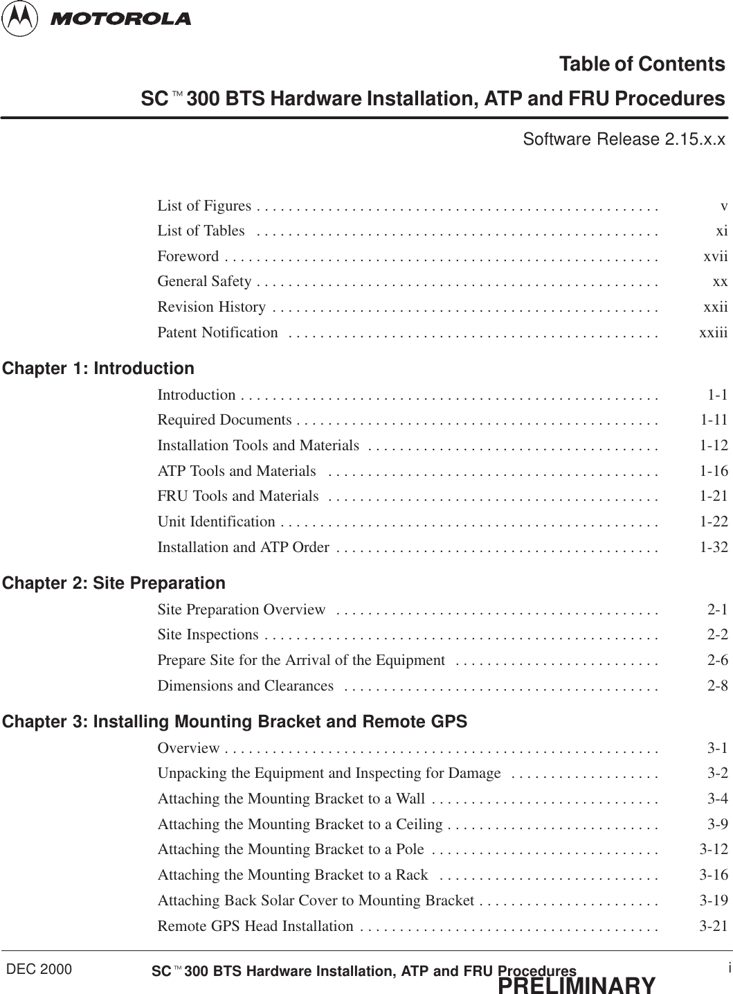
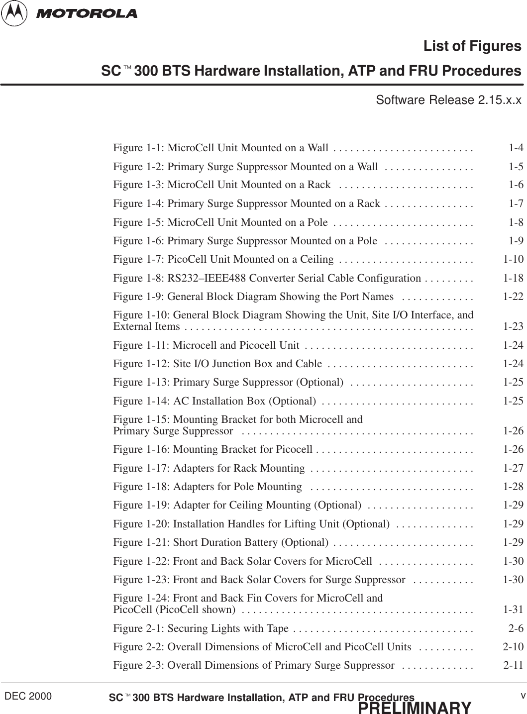

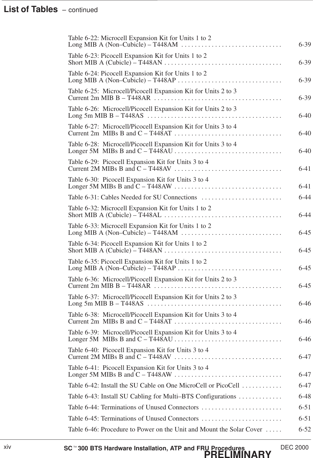
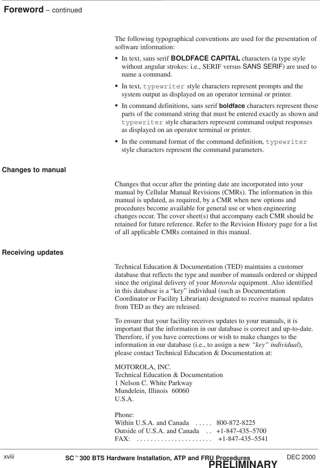
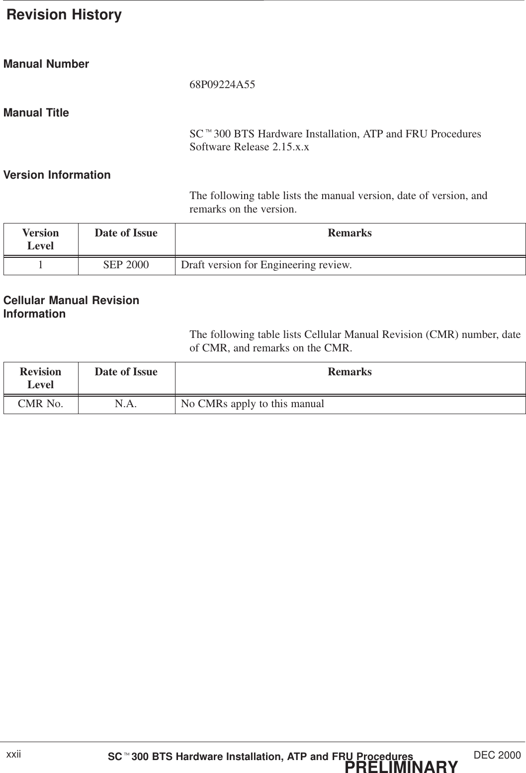
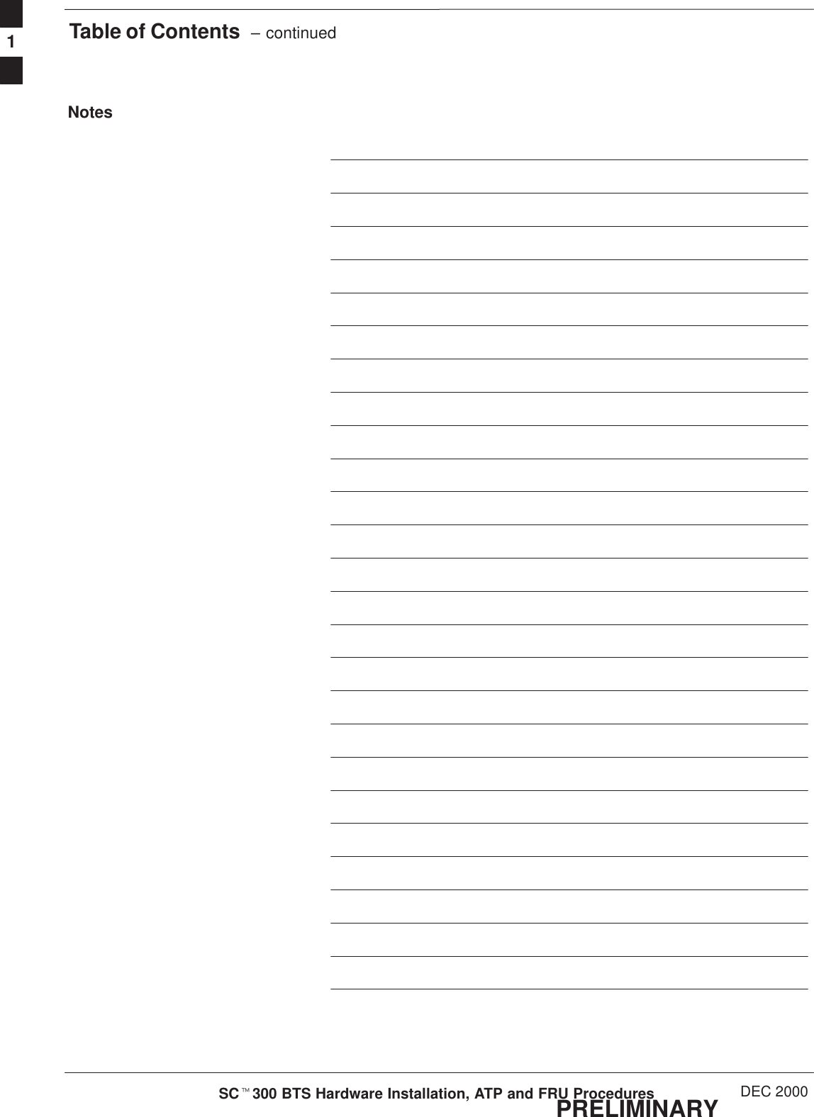
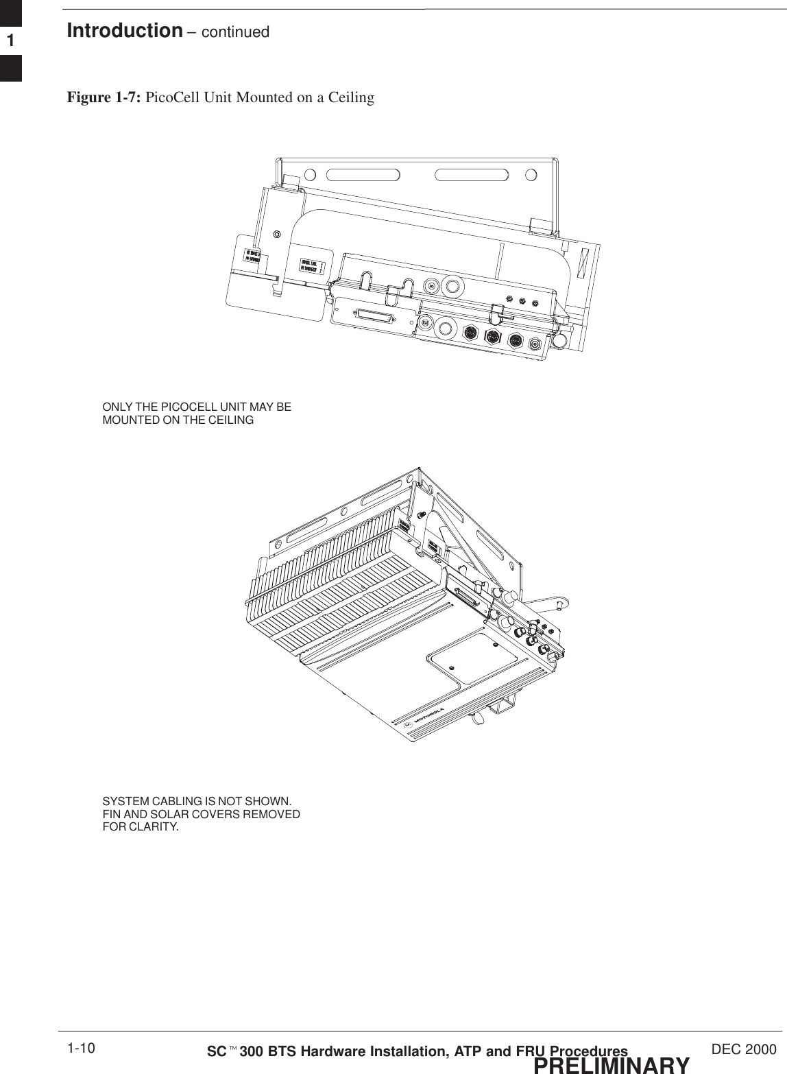
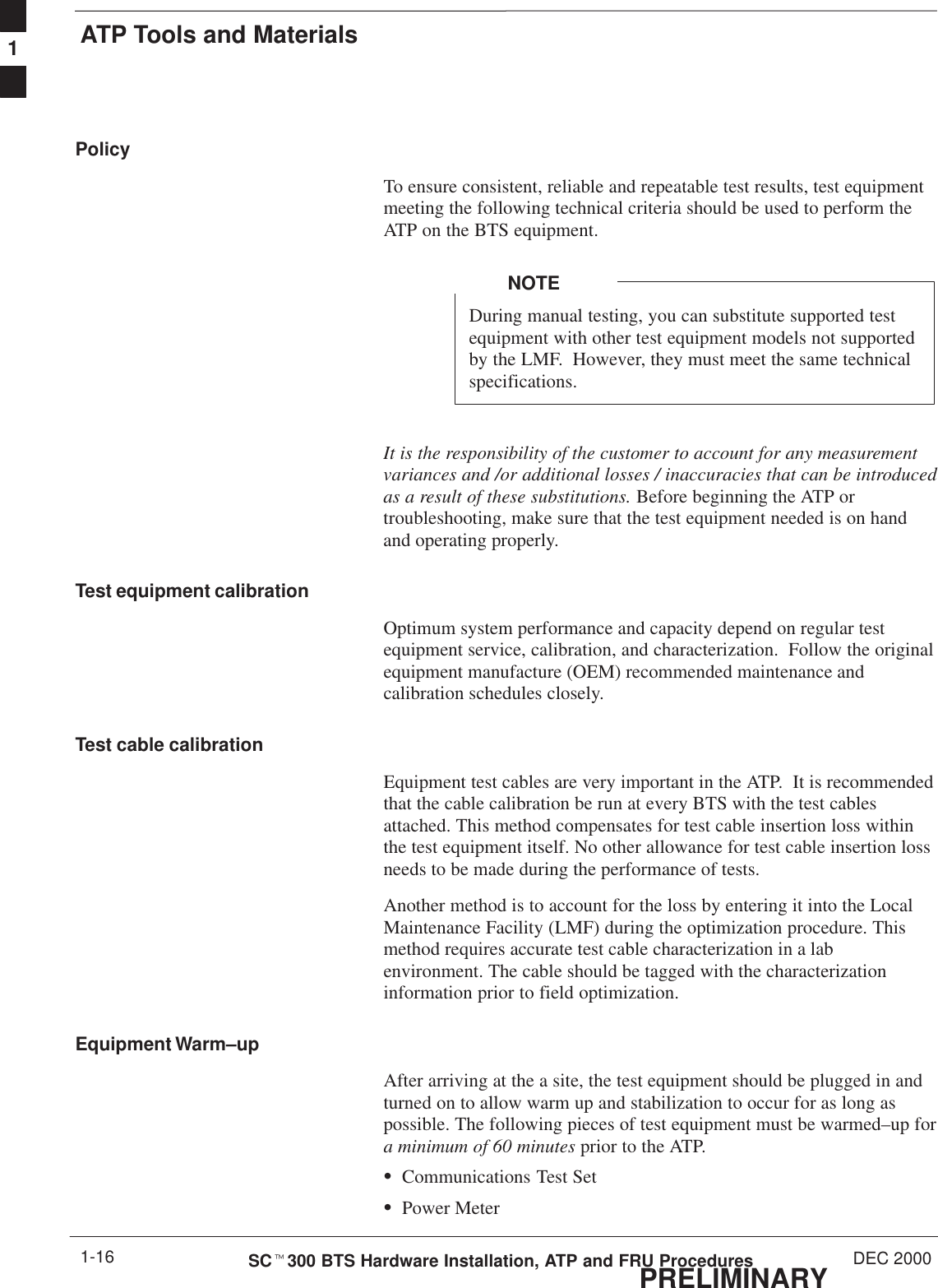

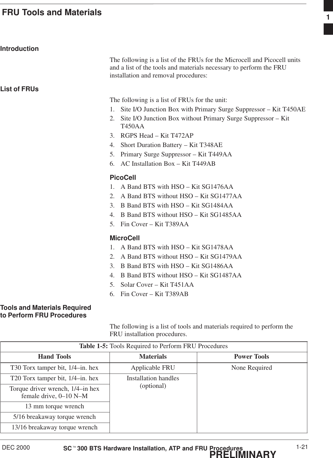
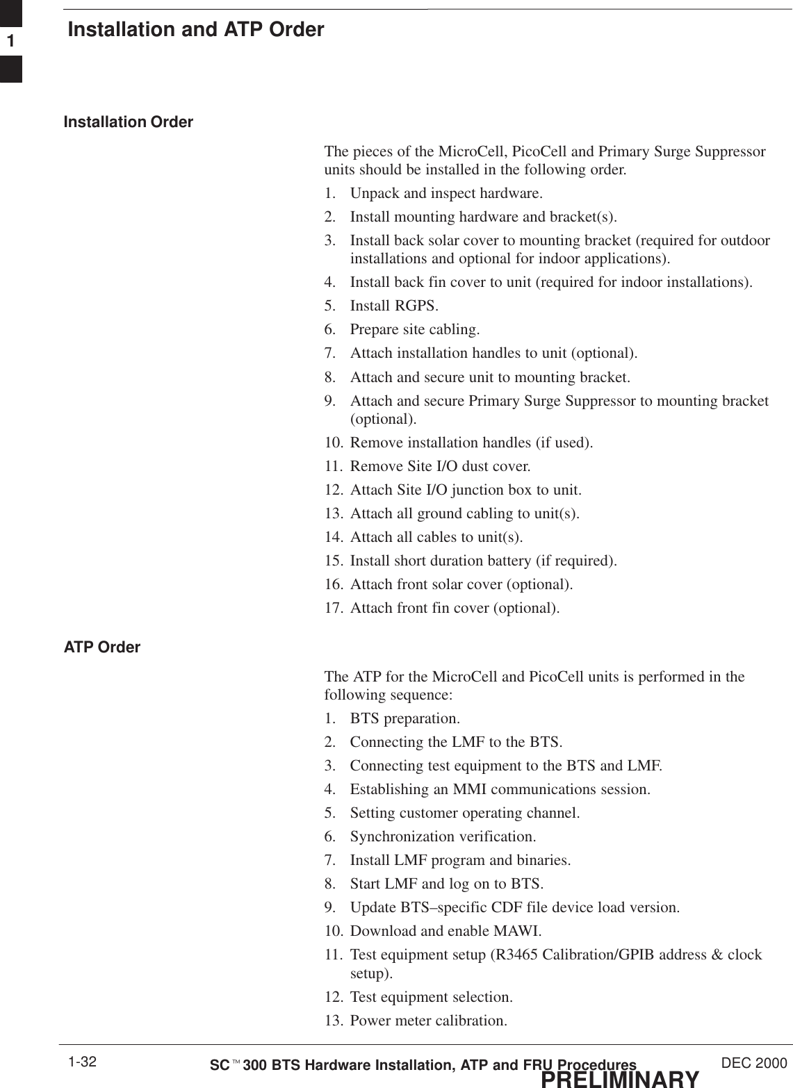
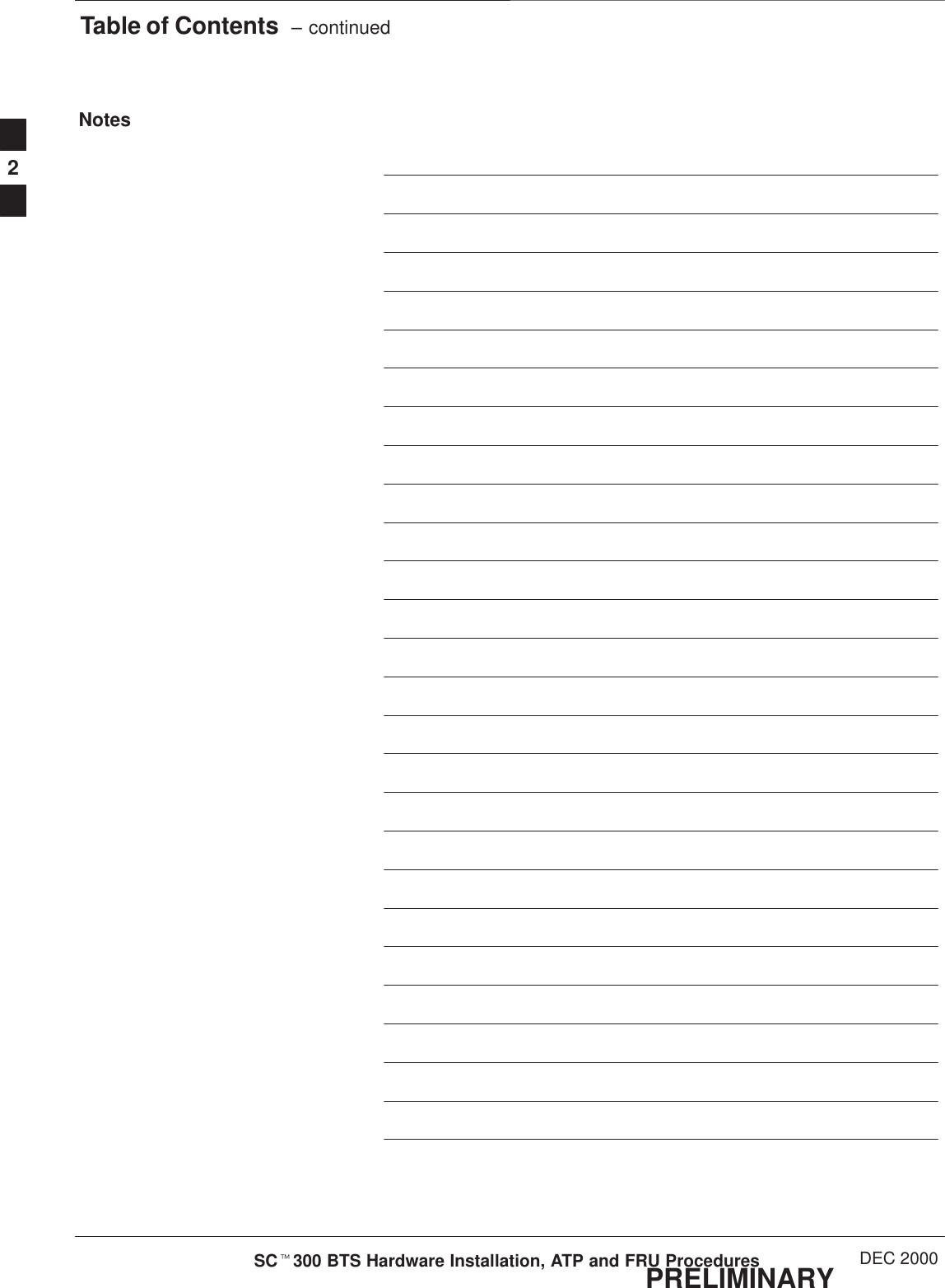
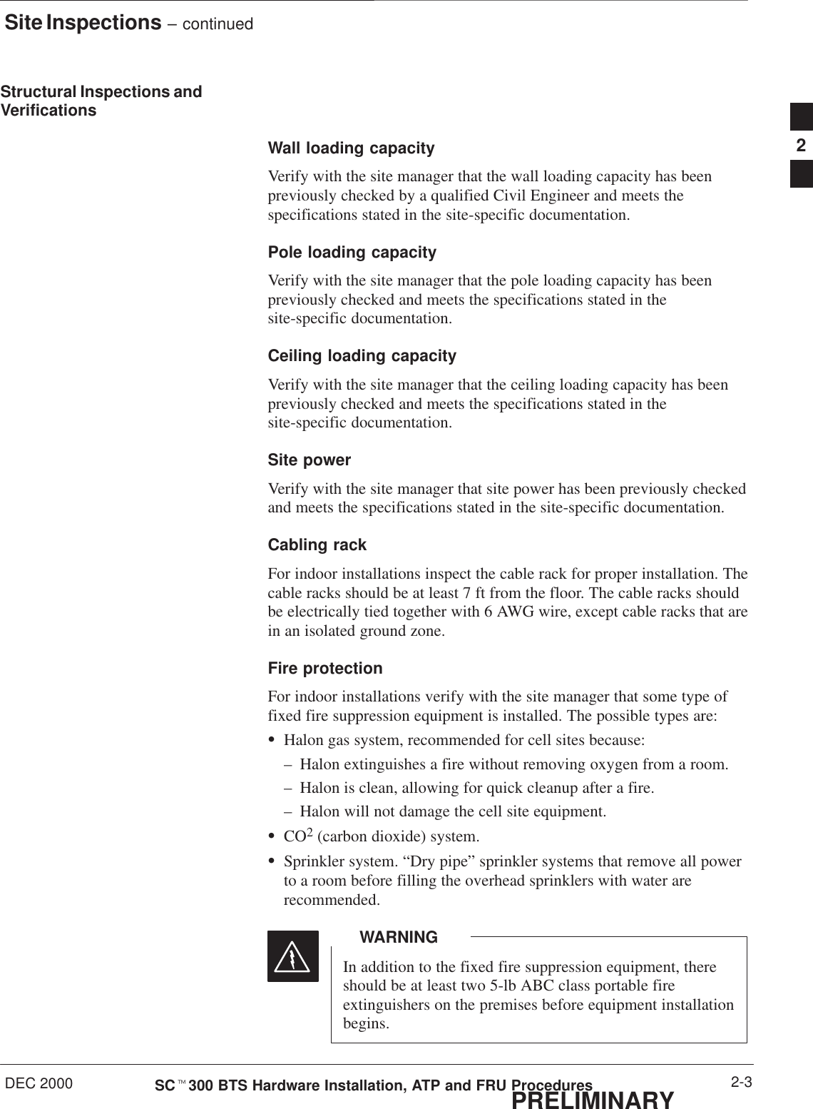
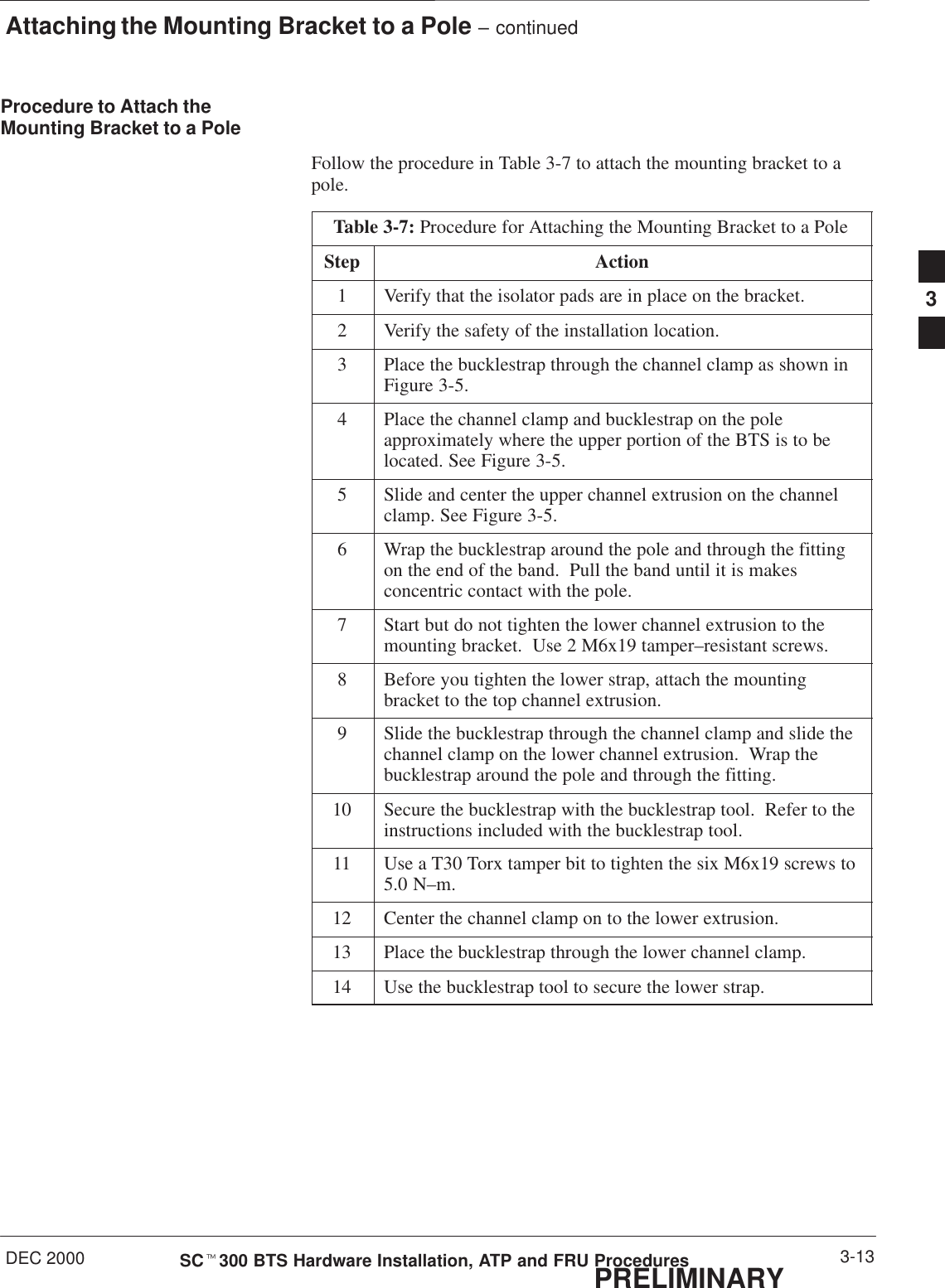
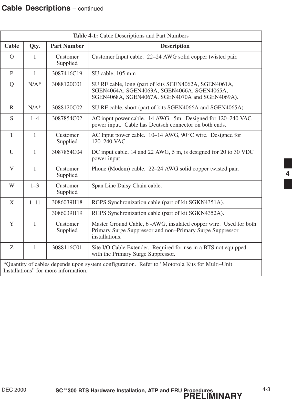
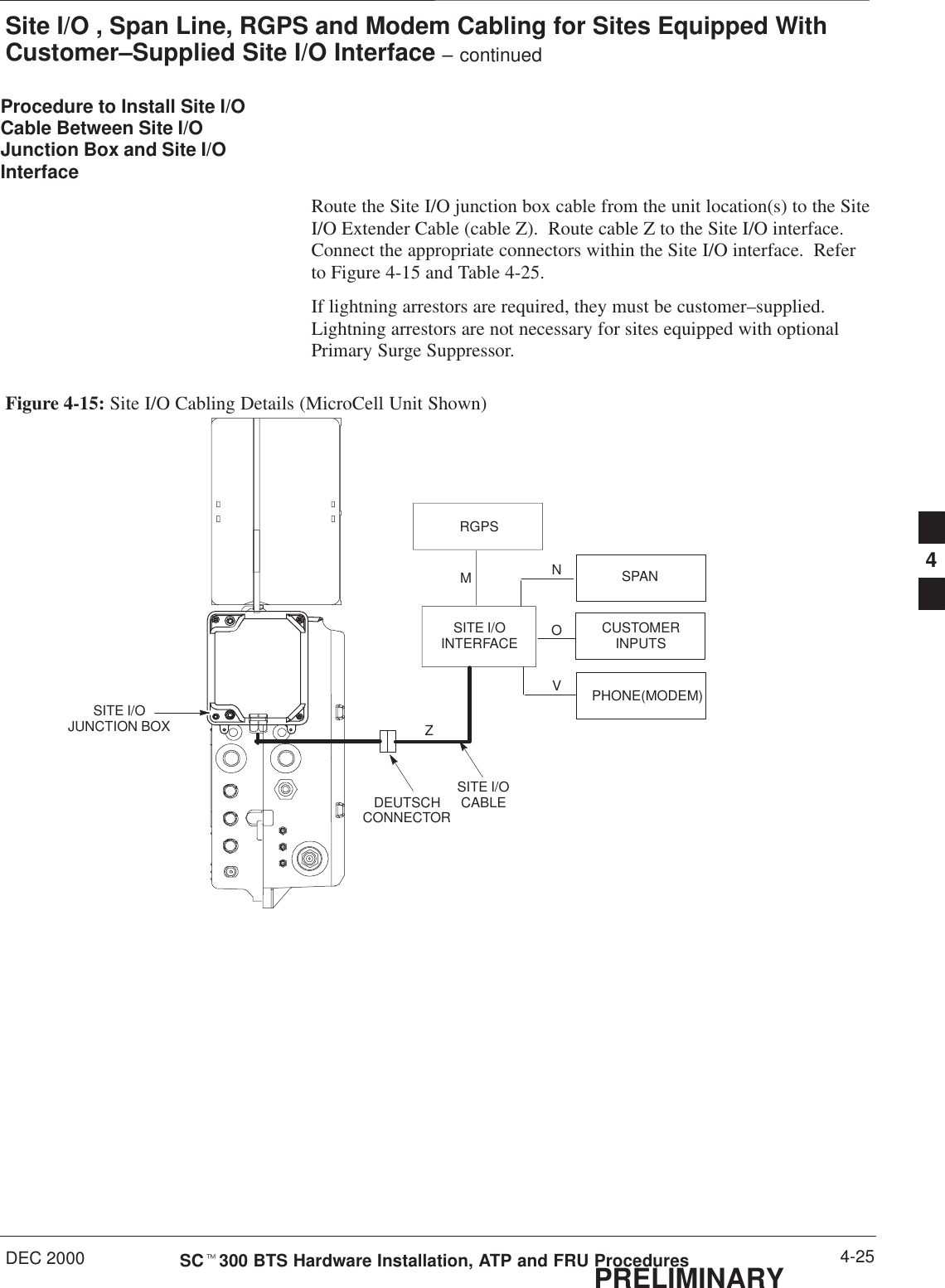
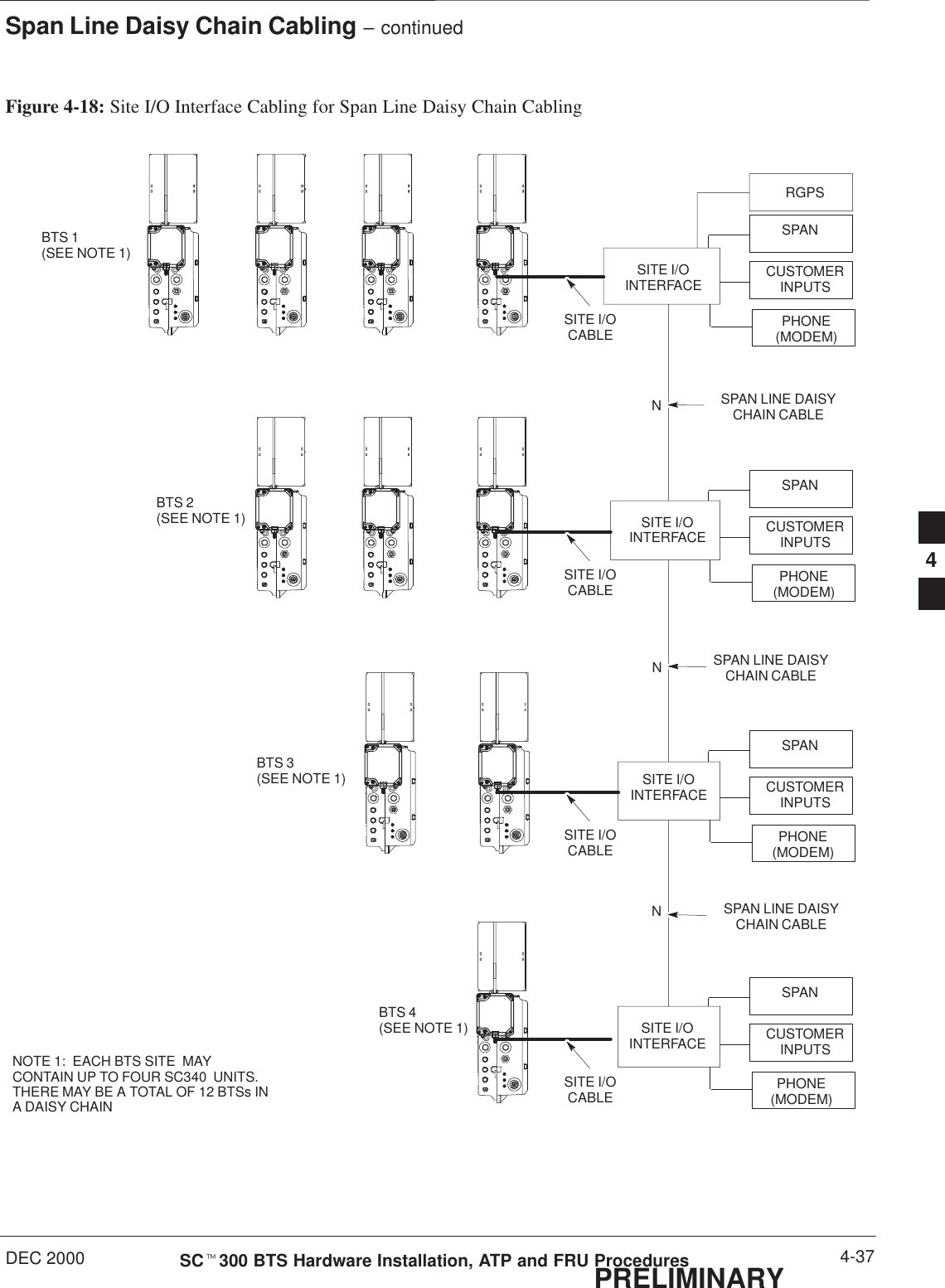
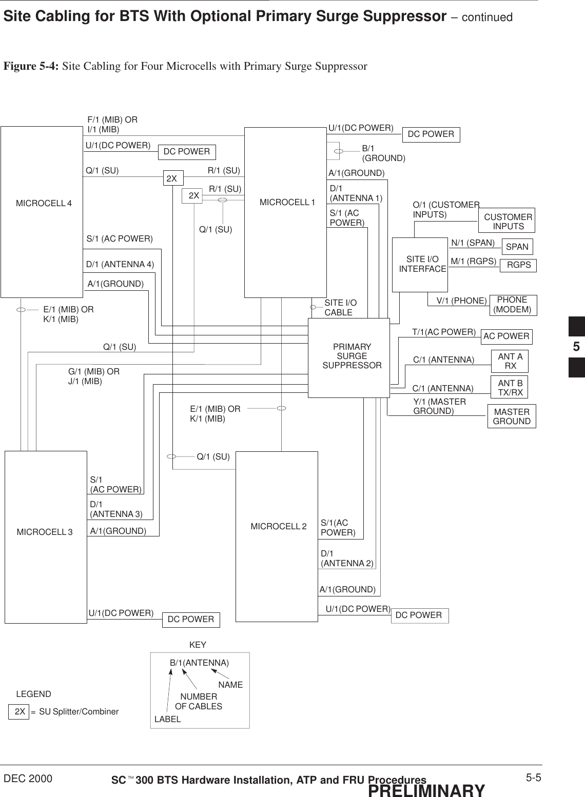
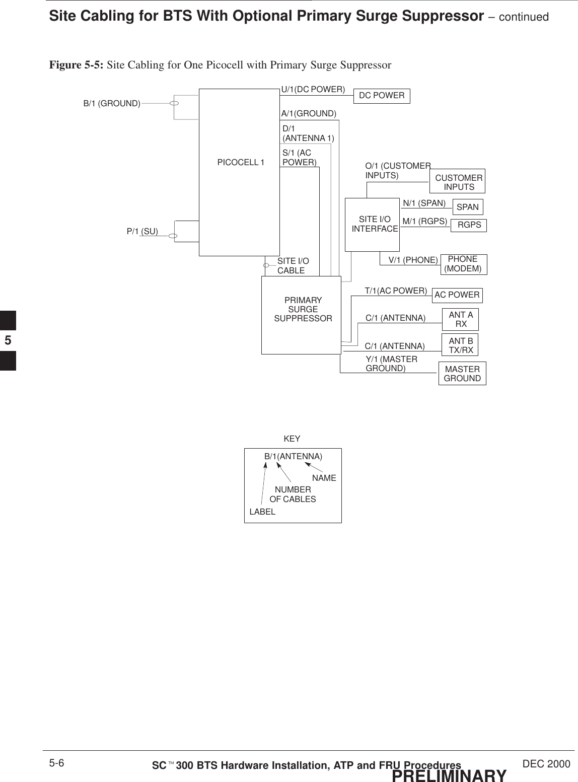
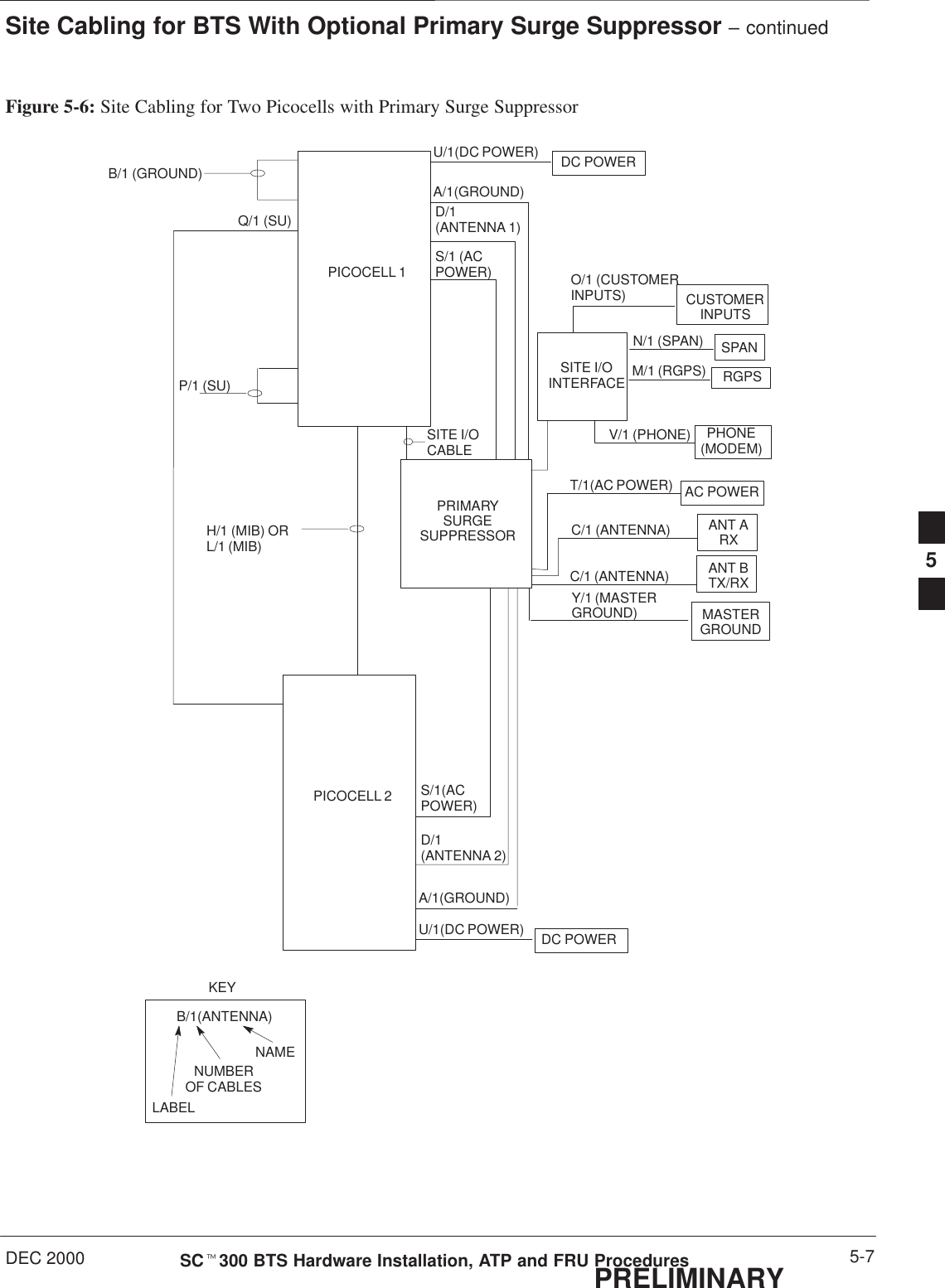
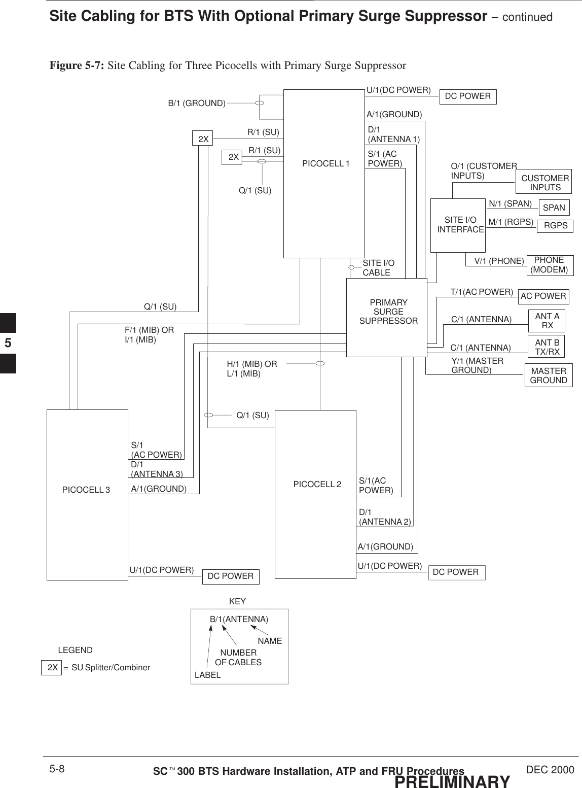
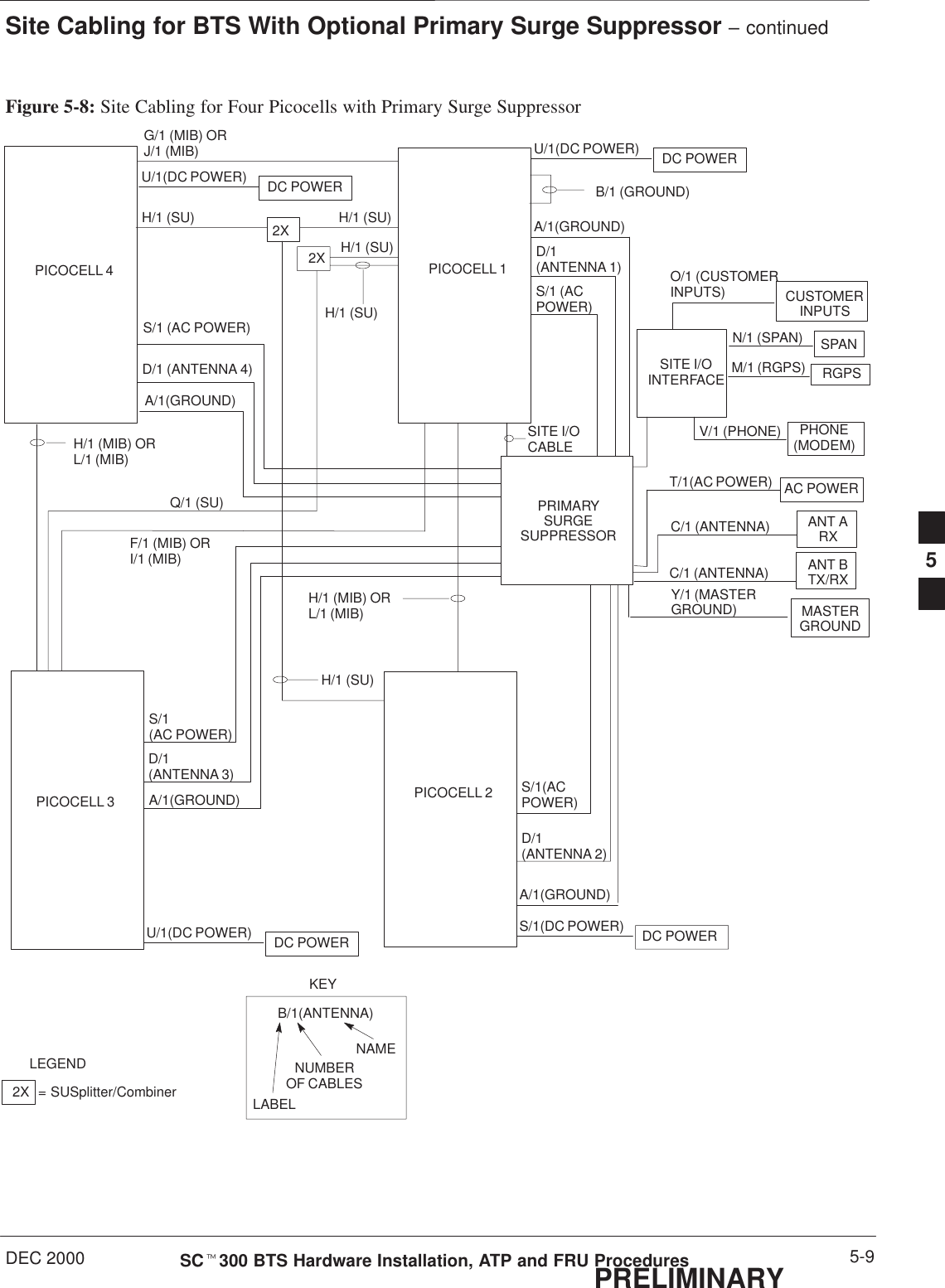
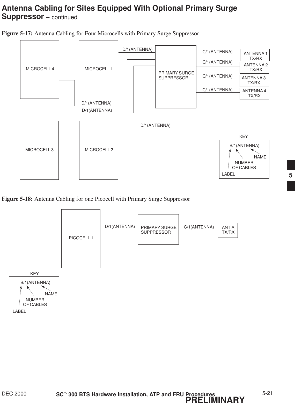
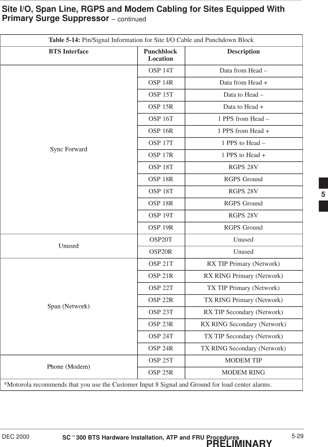
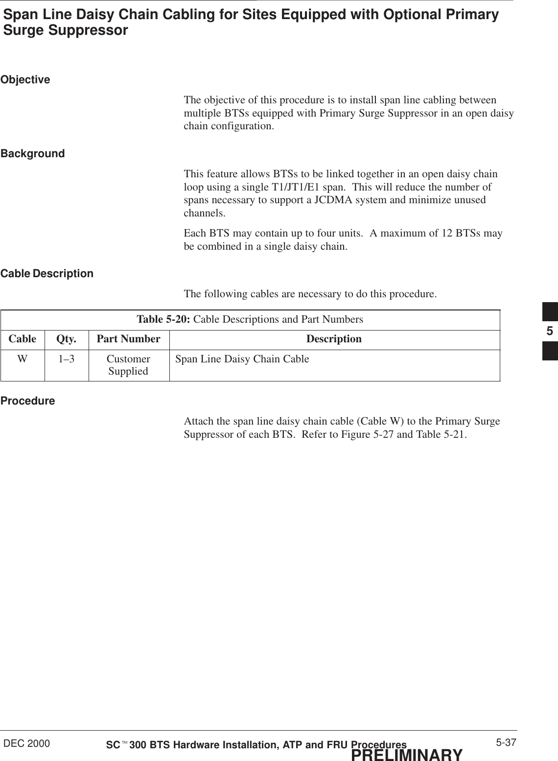
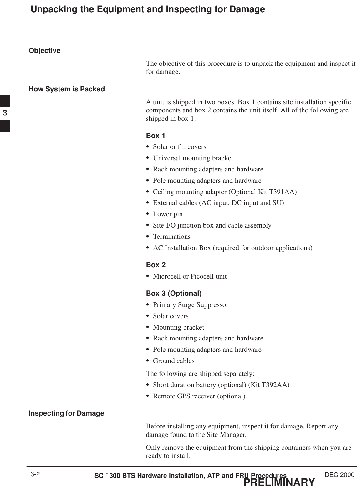
![Site Inspections – continuedDEC 2000 2-5SCt300 BTS Hardware Installation, ATP and FRU ProceduresPRELIMINARYAlarmsVerify with the site manager that any of the following alarms called outin the site-specific documentation have been installed and previouslychecked for meeting the site-specific documentation specifications.SvandalismSsurface waterSintrusionSfireSbuilding high/low temperaturesSany customer-specific options.The interface of the alarms to the Motorola equipment will be part of thecell site equipment installation.Environmental Inspections(indoor only)Temperature controlVerify with the site manager that the cell site building has beenpreviously checked for the ability to maintain a temperature range asspecified by Motorola. The life span of electronic equipment isshortened by environmental variations, even though it is designed tooperate in extreme temperatures.Grounding InspectionsFor external installationsFor outside installations refer to the site specific documentation.For internal installationsFor indoor installations refer to the Grounding Guideline for CellularRadio Installations (68P81150E62) for all grounding inspectionprocedures.Verify the following:SAll ground cables have a bend radius of 20 cm (8 inches) or more.SMetallic lines (span, phone[modem], RGPS, power and antenna) thatenter or leave the site should be equipped with a 3-electrode gas tubeprotector. The ground side of the gas tubes should be tied to theMaster Ground Bus (MGB). This is not necessary if your site isequipped with the Primary Surge Suppressor.SAll installed cable racks (in the same ground zone) are jumperedtogether.Cable racks in an Isolated Ground Zone (IGZ) are not to beconnected to a cable rack in a non-IGZ. For moreinformation on IGZ, see Grounding Guideline for CellularRadio Installations, Motorola part number 68P81150E62.WARNING2](https://usermanual.wiki/Nokia-Solutions-and-Networks/T6AQ2.1-of-2/User-Guide-141659-Page-69.png)
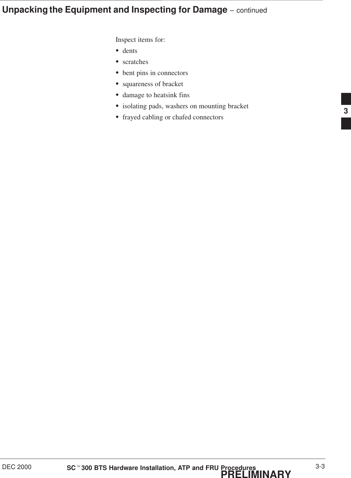
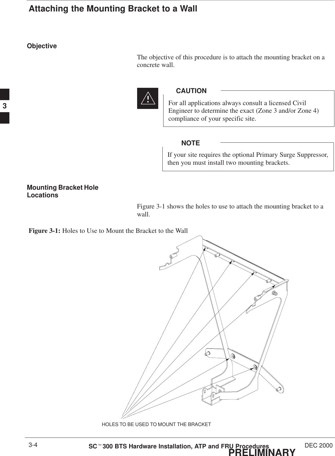
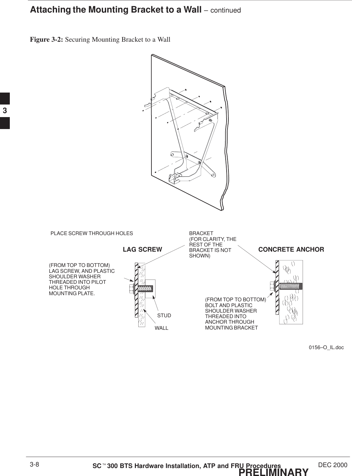
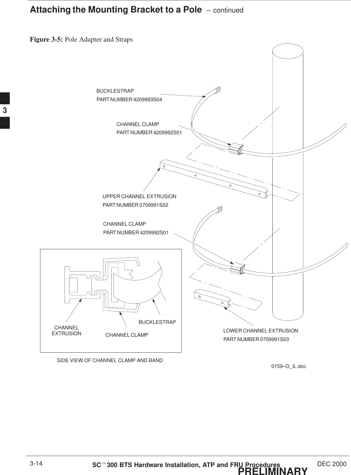
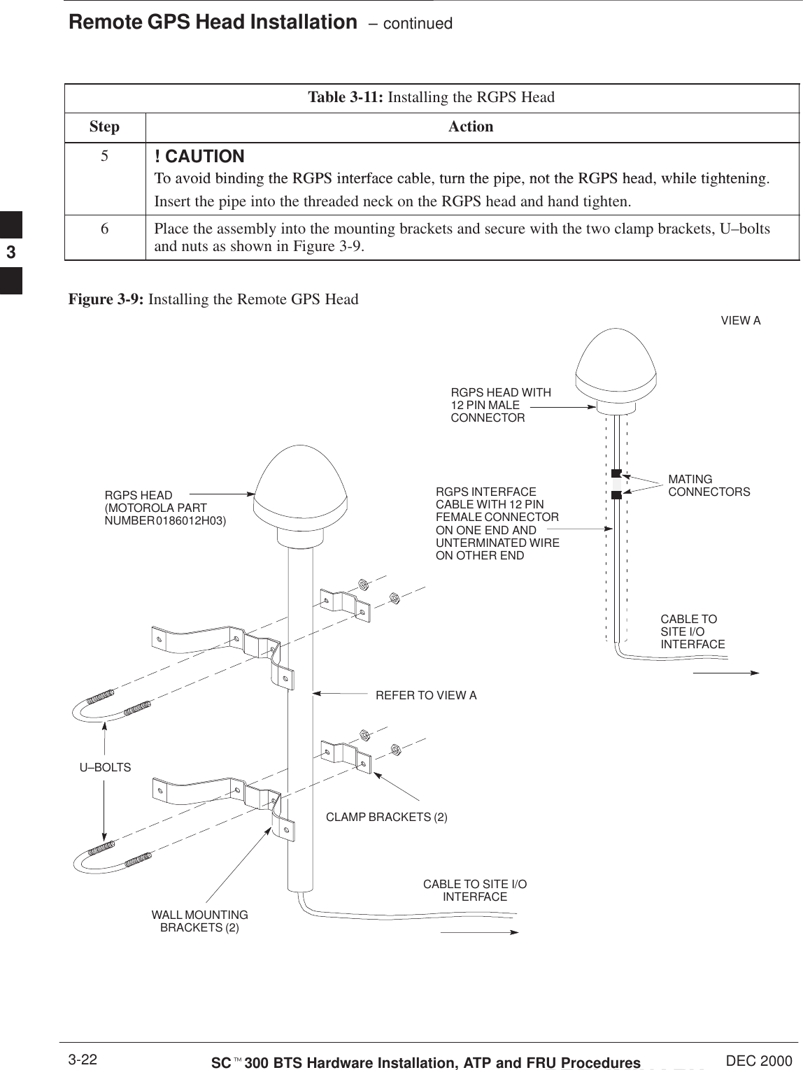
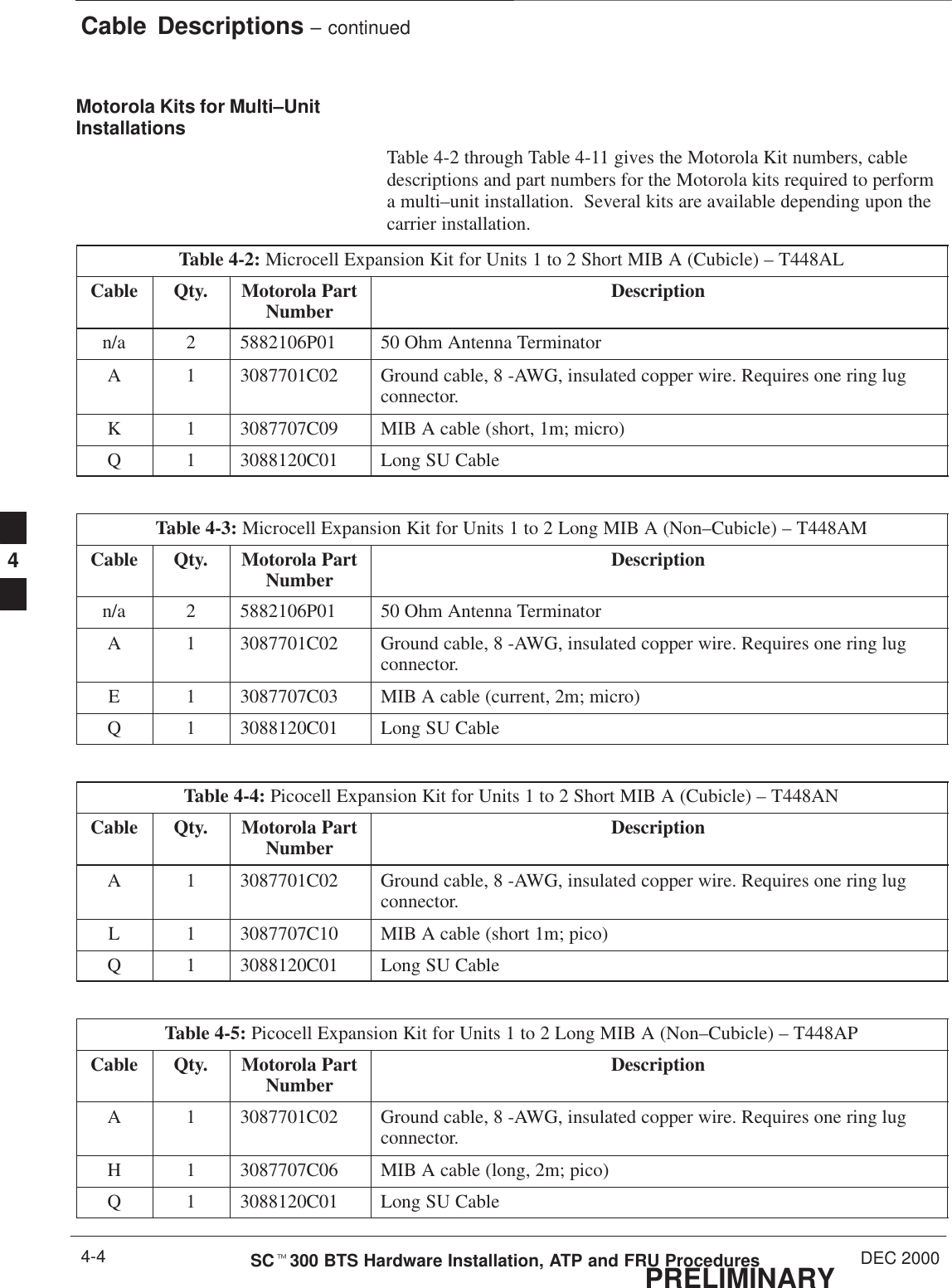
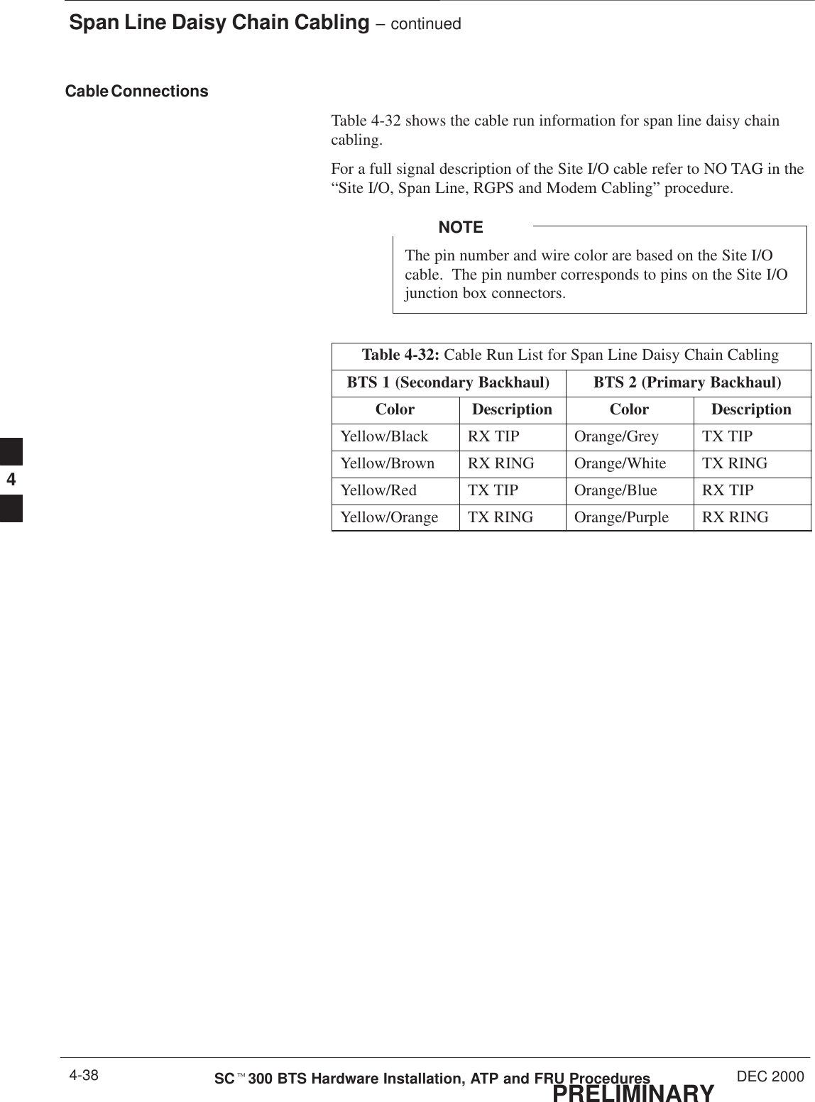
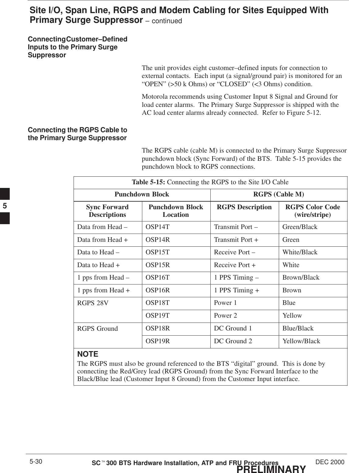
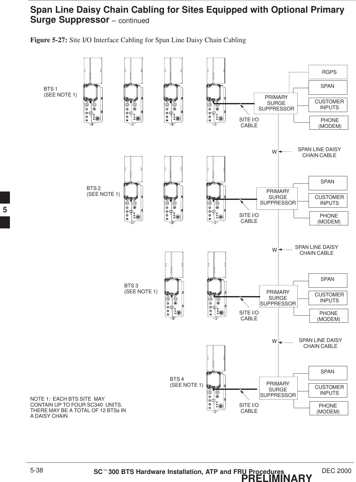
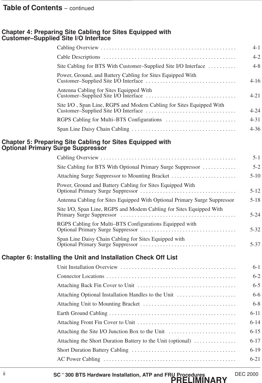
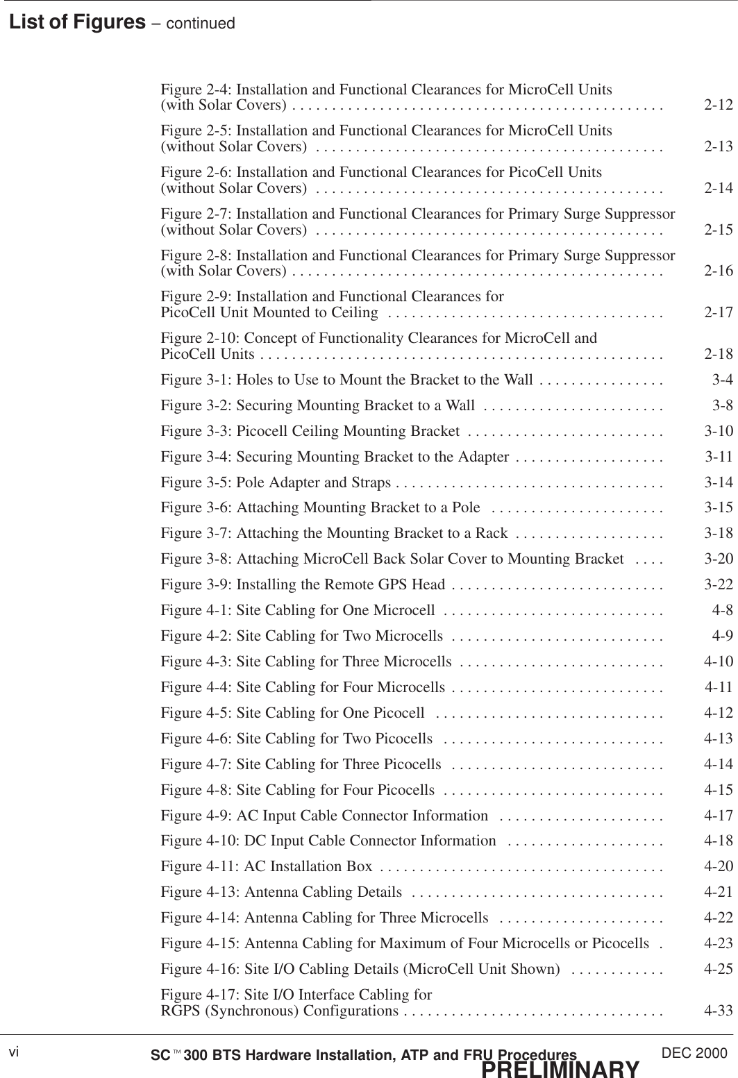
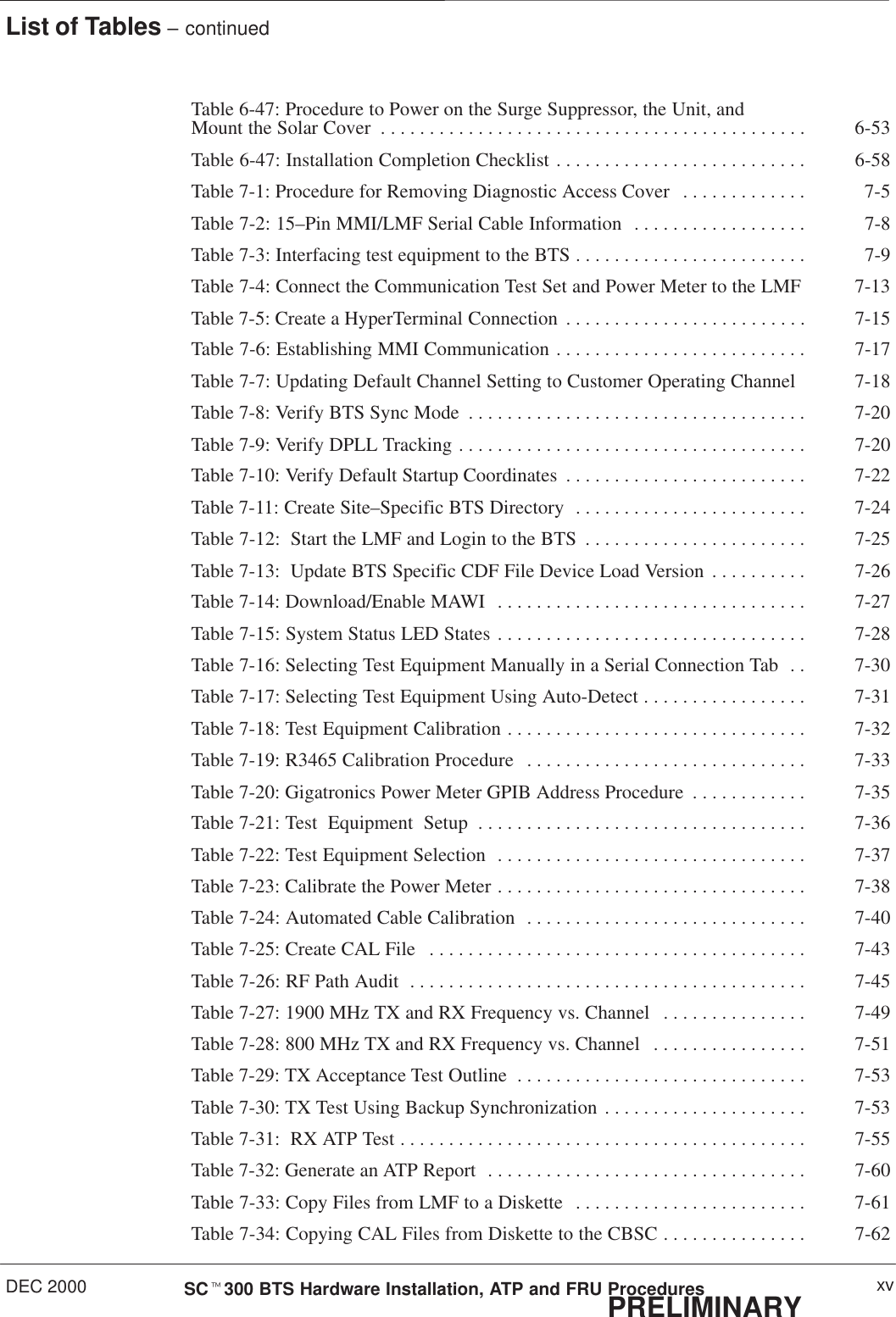
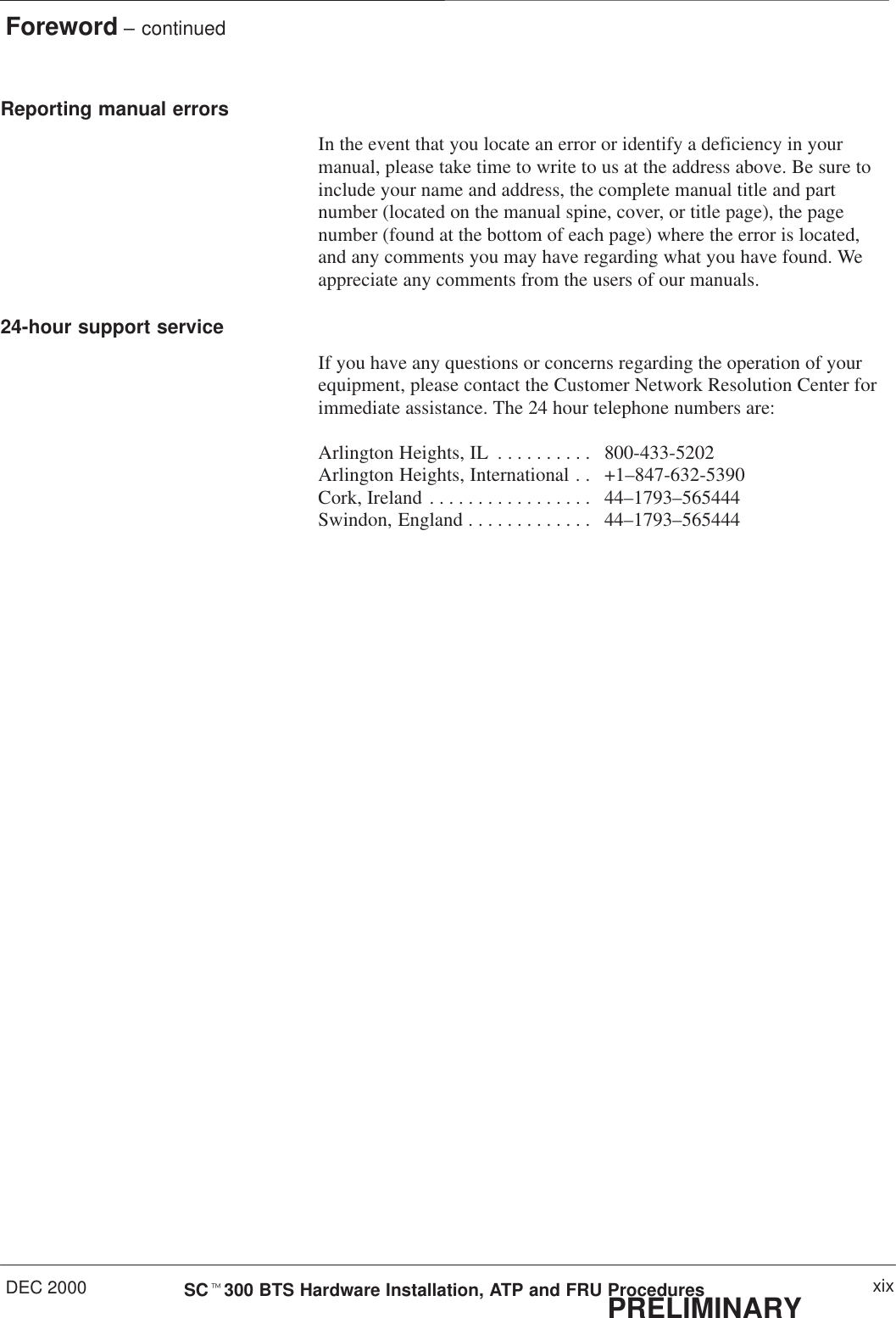
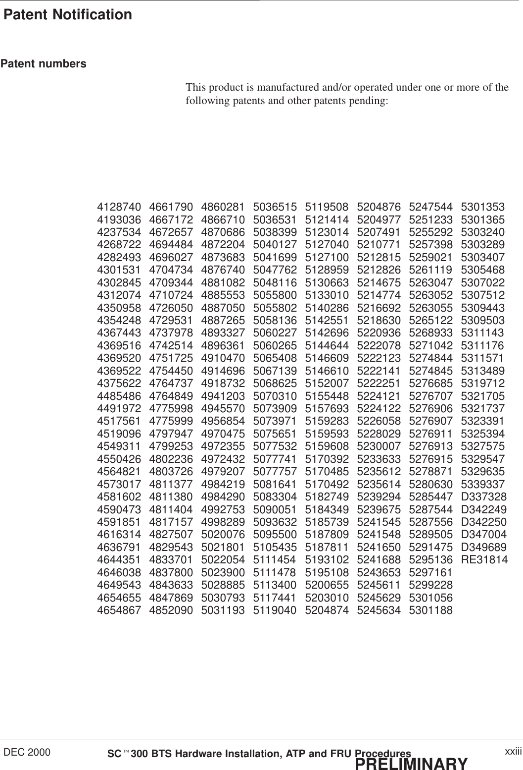
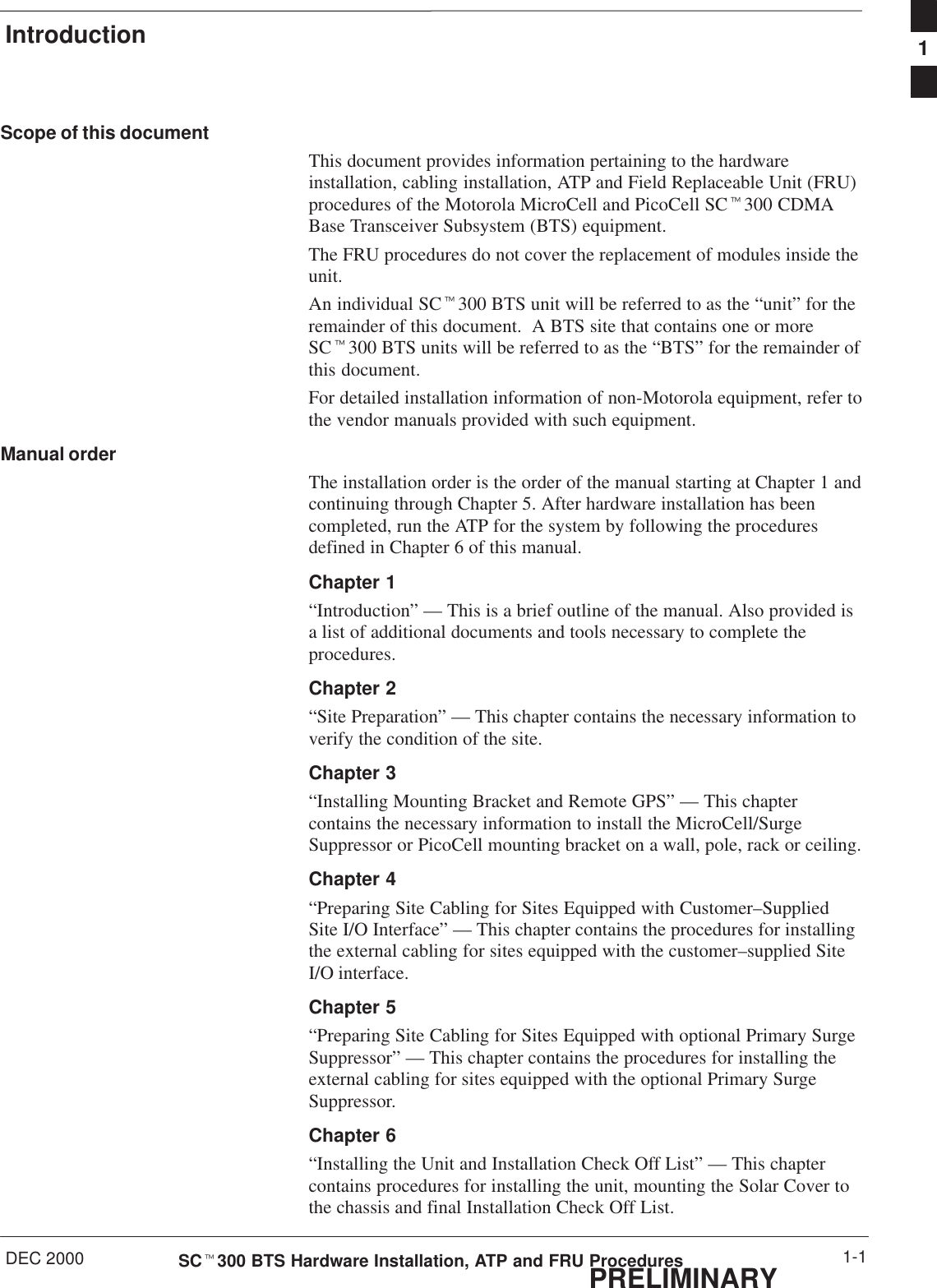
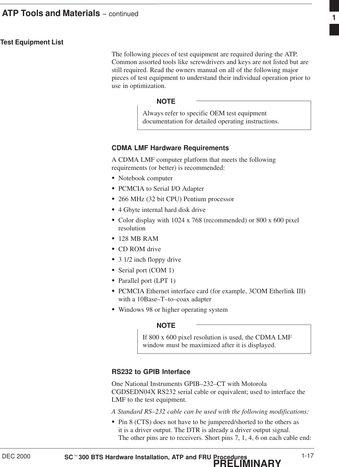
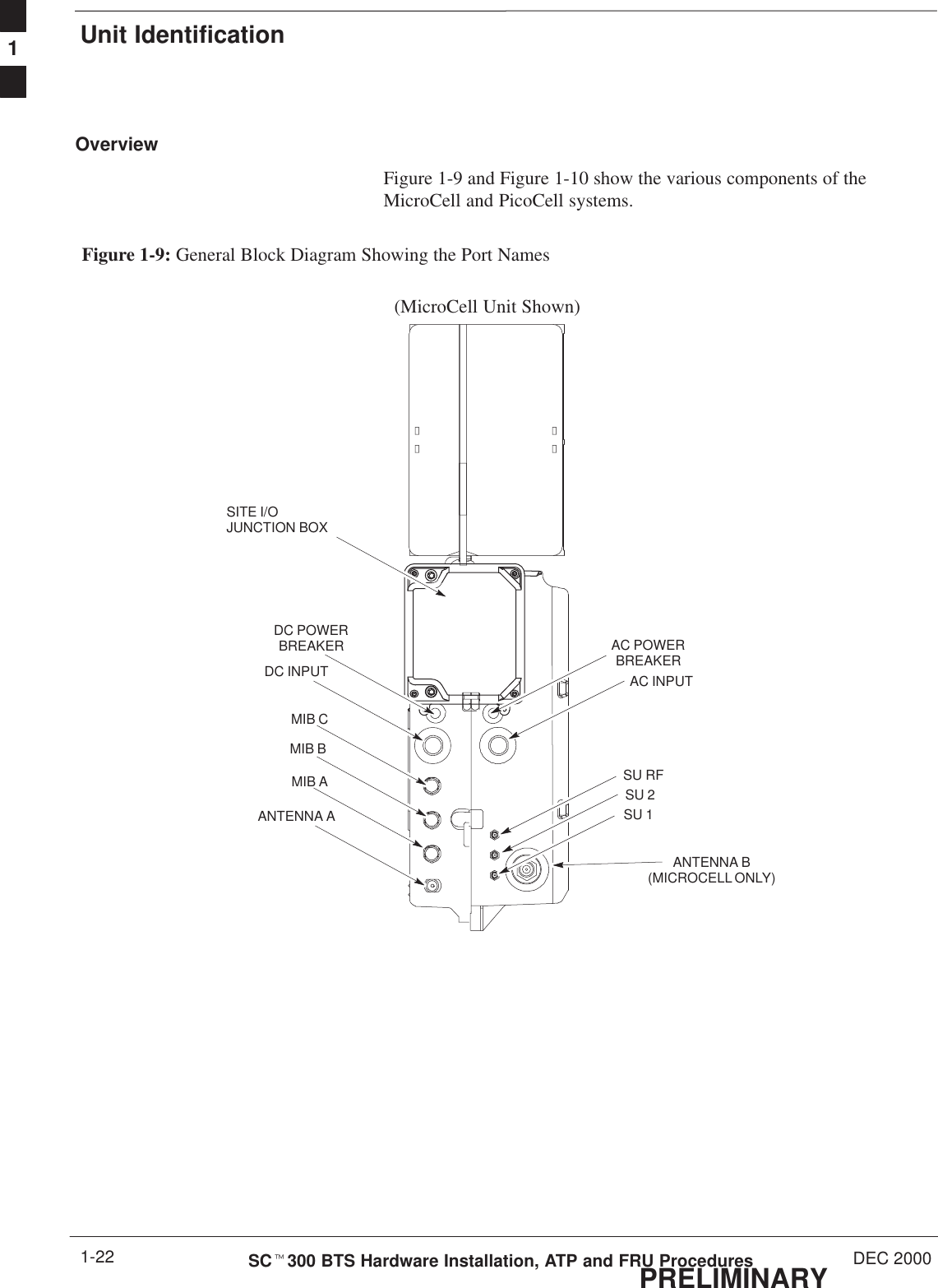
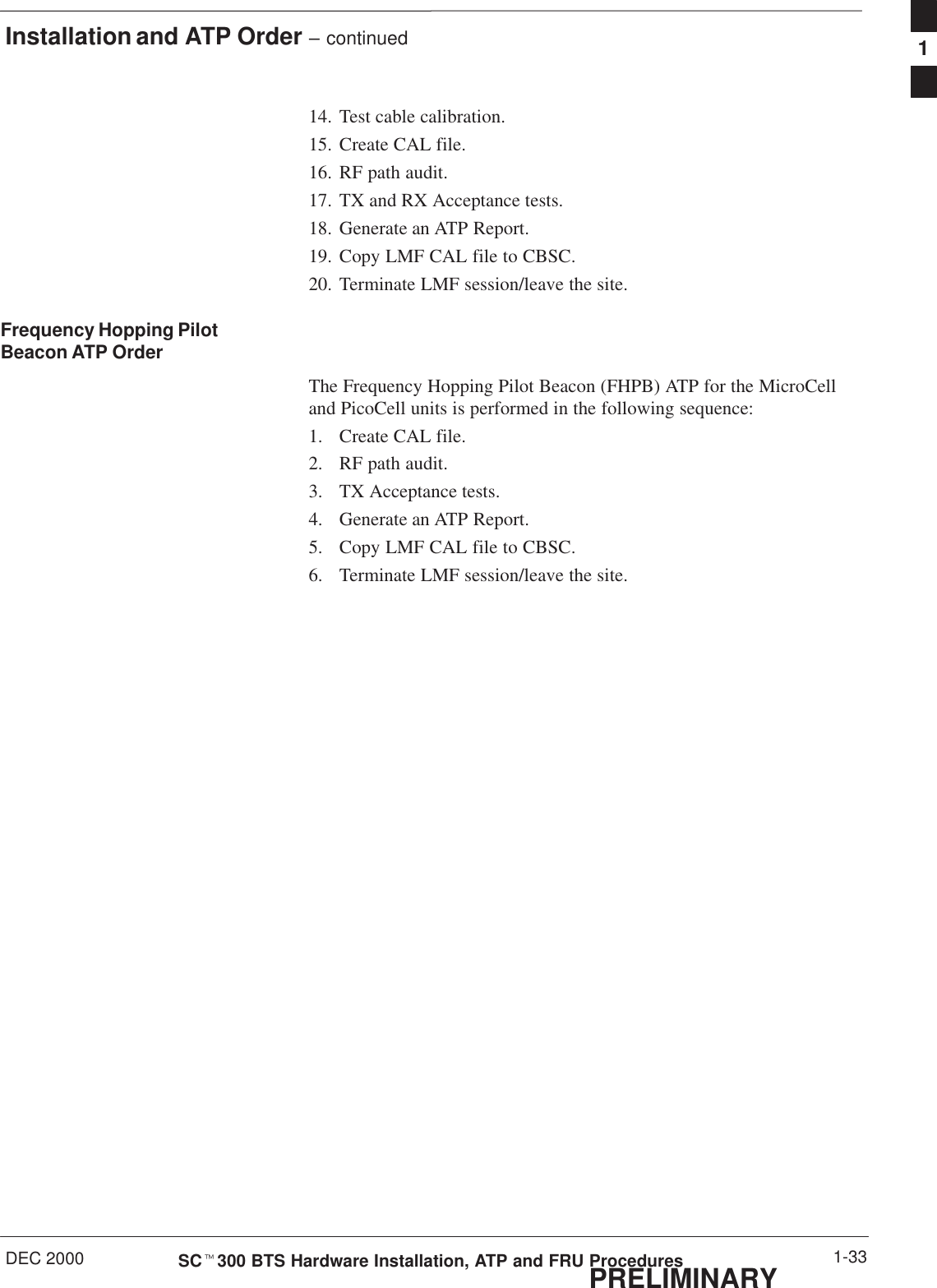
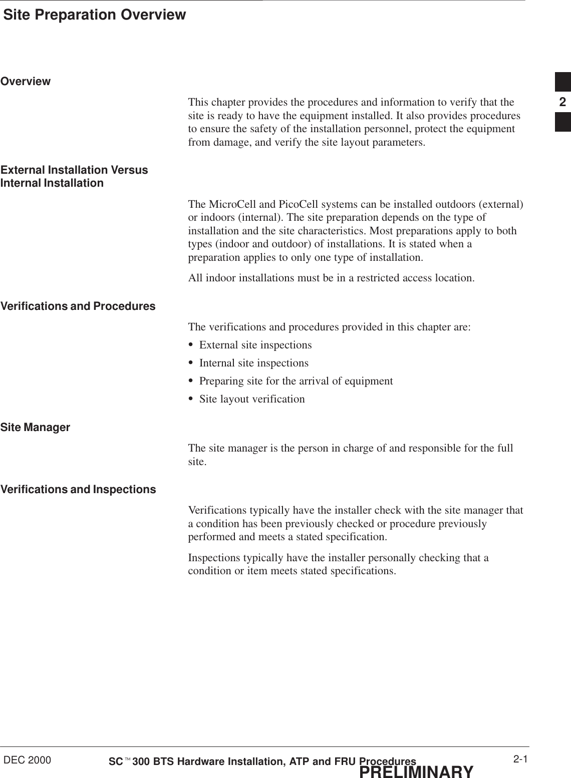
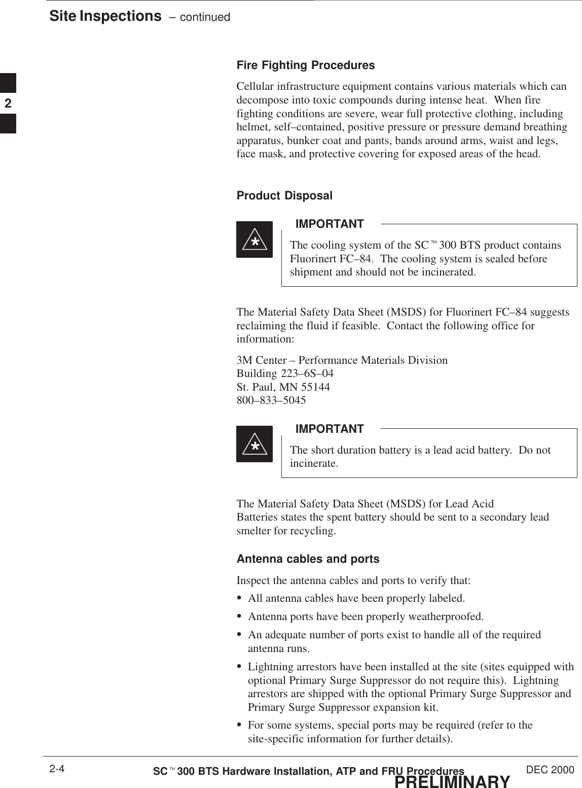
![Attaching the Mounting Bracket to a PolePRELIMINARYSCt300 BTS Hardware Installation, ATP and FRU Procedures DEC 20003-12ObjectiveThe objective of this procedure is to attach the mounting bracket to apole.The mounting pole structure must be reviewed for itsability to support the weight of the MicroCell [38.5 kg(84.7 lbs.)]; PicoCell [30.5 kg (67.1 lbs.)] and PrimarySurge Suppressor [19.17 kg (42.26 lbs.)] under high winds,earthquakes, etc.SInstalling the BTS on an inadequate pole may result inserious personal injury even death or damage to theequipment.SPlacement of the BTS should not present a hazard topedestrians by impeding passage, nor to field service personnel by being placed near high voltage or other hazardous conditions.SAll cabling must be constrained in or on the pole inaccordance to local building codes.WARNINGFor all applications always consult a licensed CivilEngineer to determine the exact (Zone 3 and/or Zone 4)compliance of your specific site.CAUTIONRequired Tools and Materialsfor Pole MountingThe following tools and materials are required to properly and safelyinstall the mounting bracket to a pole.Table 3-6: Tools and Materials for Pole MountingHand Tools Materials Power ToolsSafety Glasses MicroCell or PicoCellMounting Kit No Power Tools RequiredBucklestrap Cutting Tool (Motorolapart number 6604809N01) electrical tapeT30 Torx tamper bit, 1/4–in. hexTorque driver wrench, 1/4–in. hexfemale drive, 0–10 N–MBall Peen (Metal Working) HammerHeavy GlovesTape Measure3](https://usermanual.wiki/Nokia-Solutions-and-Networks/T6AQ2.1-of-2/User-Guide-141659-Page-96.png)