Nokia Solutions and Networks T6AQ2 SC300 Microcell 1.9GHz User Manual frtcov
Nokia Solutions and Networks SC300 Microcell 1.9GHz frtcov
UserManual.wiki
>
Nokia Solutions and Networks
>
T6AQ2 User Manual
>
2 of 2
Contents
1.
1 of 2
2.
2 of 2
2 of 2
Navigation menu
Upload a User Manual
Namespaces
Wiki Guide
HTML
PDF
Info
Views
User Manual
Discussion / Help
Navigation

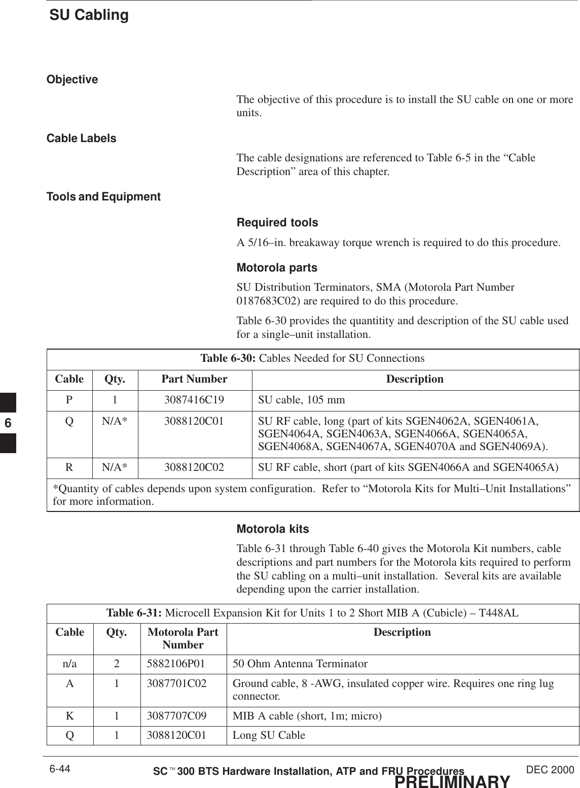

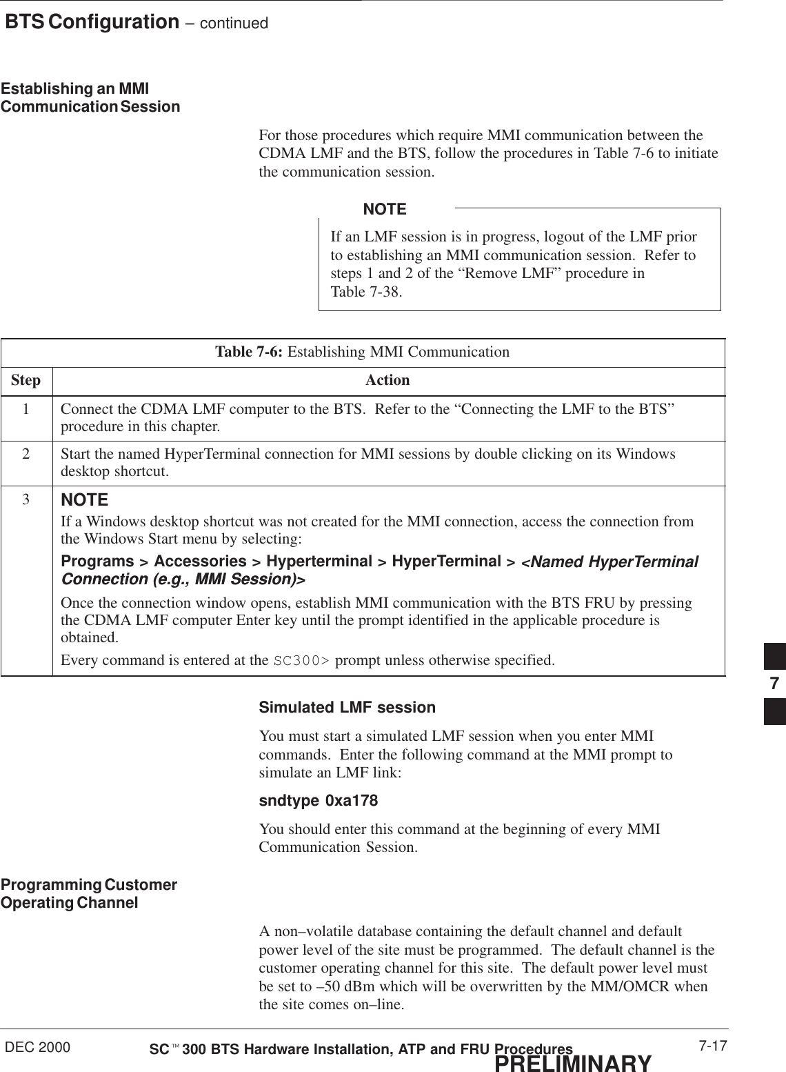
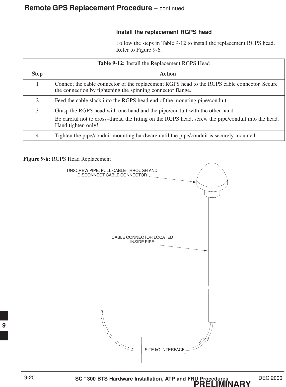
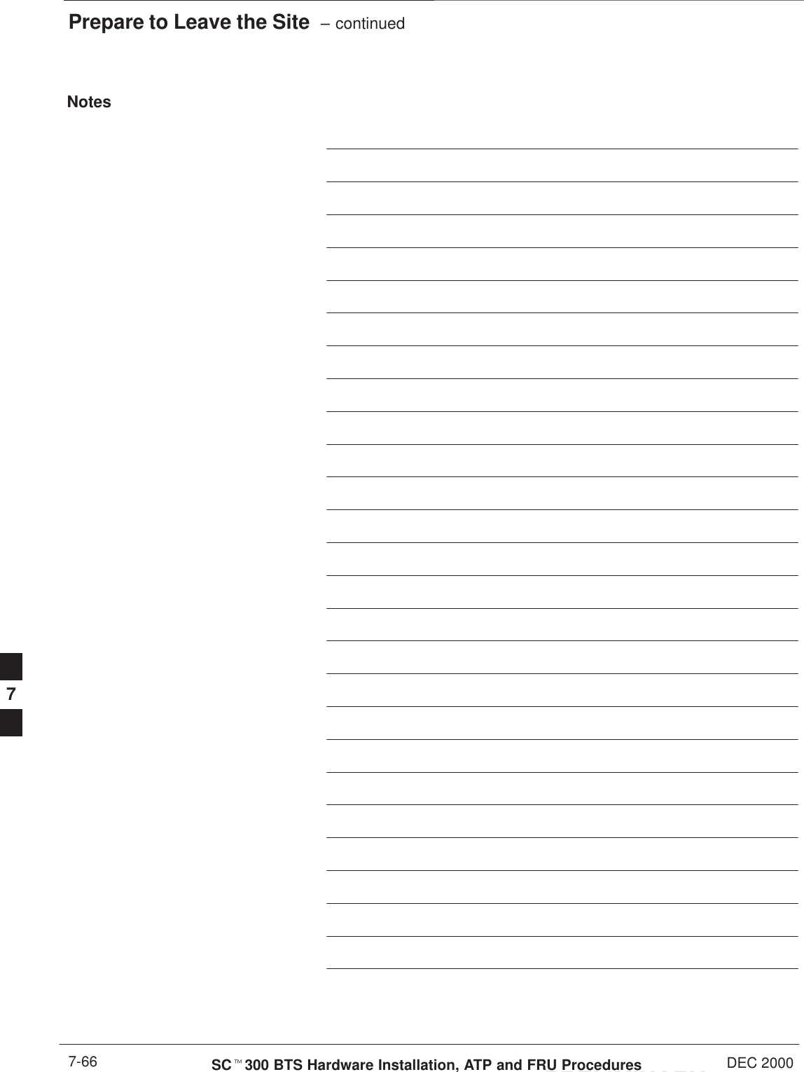
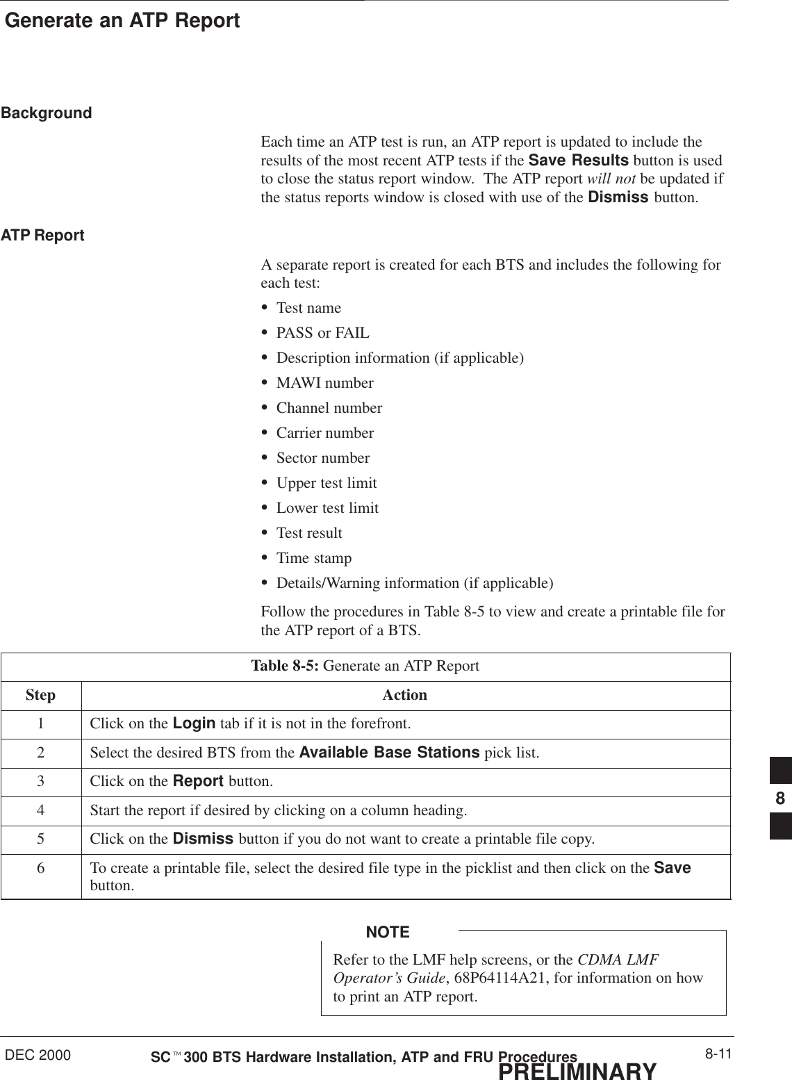
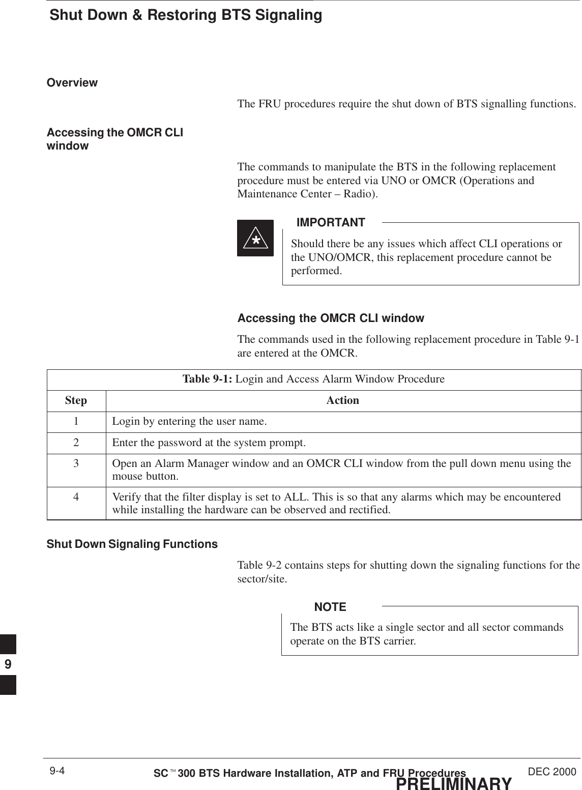
![BTS Configuration – continuedDEC 2000 7-21SCt300 BTS Hardware Installation, ATP and FRU ProceduresPRELIMINARYTable 7-9: Verify DPLL TrackingStep Action7Enter the gps_status command to display the current state of the RGPS. Observe the followingtypical response:gps_statusGPS Receiver Identification:Current GPS Time :8 03 1999 23:01:12Current GPS Receiver Status :8Number of Satellites Currently visible :11Number of Satellites Currently received :5Number of Satellites Currently tracked :5GPS Receiver Type :UTCurrent GPS Task State :GPS_TRACKCurrent Dilution of Precision (HDOP (2D)/antenna ok [0x01]): 0Chan: 0, SVID: 9, Mode: 8, RSSI: 44, Status: 0xaaChan: 1, SVID: 4, Mode: 8, RSSI: 46, Status: 0xaaChan: 2, SVID: 10, Mode: 8, RSSI: 44, Status: 0xaaChan: 3, SVID: 6, Mode: 8, RSSI: 41, Status: 0xaaChan: 4, SVID: 7, Mode: 8, RSSI: 43, Status: 0xaaChan: 5, SVID: 24, Mode: 8, RSSI: 47, Status: 0xaaChan: 6, SVID: 30, Mode: 8, RSSI: 45, Status: 0xaaChan: 7, SVID: 5, Mode: 8, RSSI: 48, Status: 0xaaCurrent Longitude: –350250952Current Latitude: 118244730Current Height: 240198The RGPS must have a Current GPS Task State of GPS_TRACK to proceed.NOTENOTEGPS tracking times vary depending on location and installation.9Issue the dpll_status command to display the current state of the DPLL. Observe the followingtypical response:Current source set to: GPS referenceDPLL control task state: DPLL track.DPLL status (not valid if using even sec src): c:0000 off: –8639450,6736579,7204904 TK(Note: This must say TK. A1 and A2 states will have preceded it)Mode cntr: 120 ip: 9, iq: 4aip1: 9, aiq1: 4aip2: 6, aiq2: –2 tip: 3, tiq: –9integrator: 4096 . . . continued on next page7](https://usermanual.wiki/Nokia-Solutions-and-Networks/T6AQ2.2-of-2/User-Guide-141660-Page-89.png)
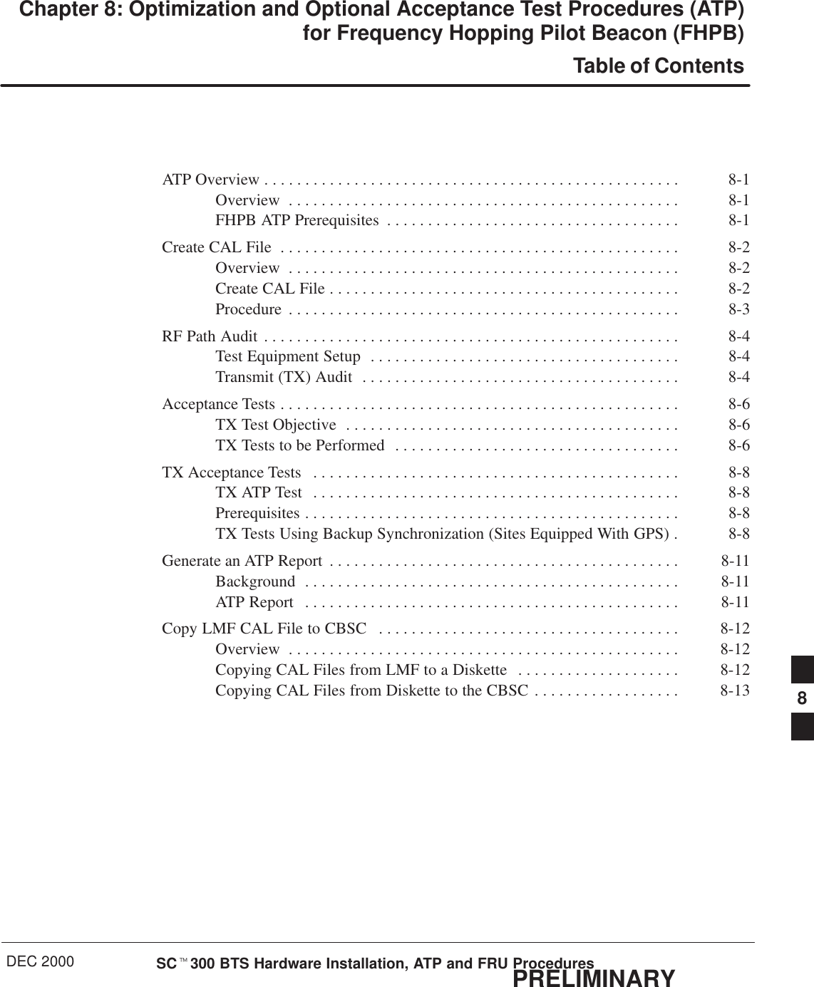

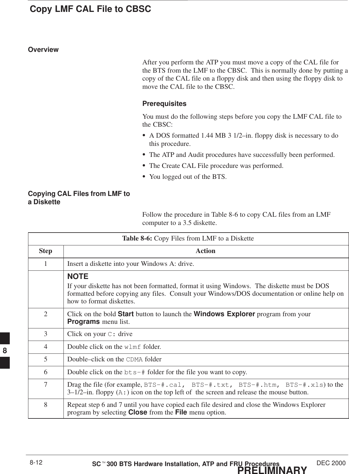

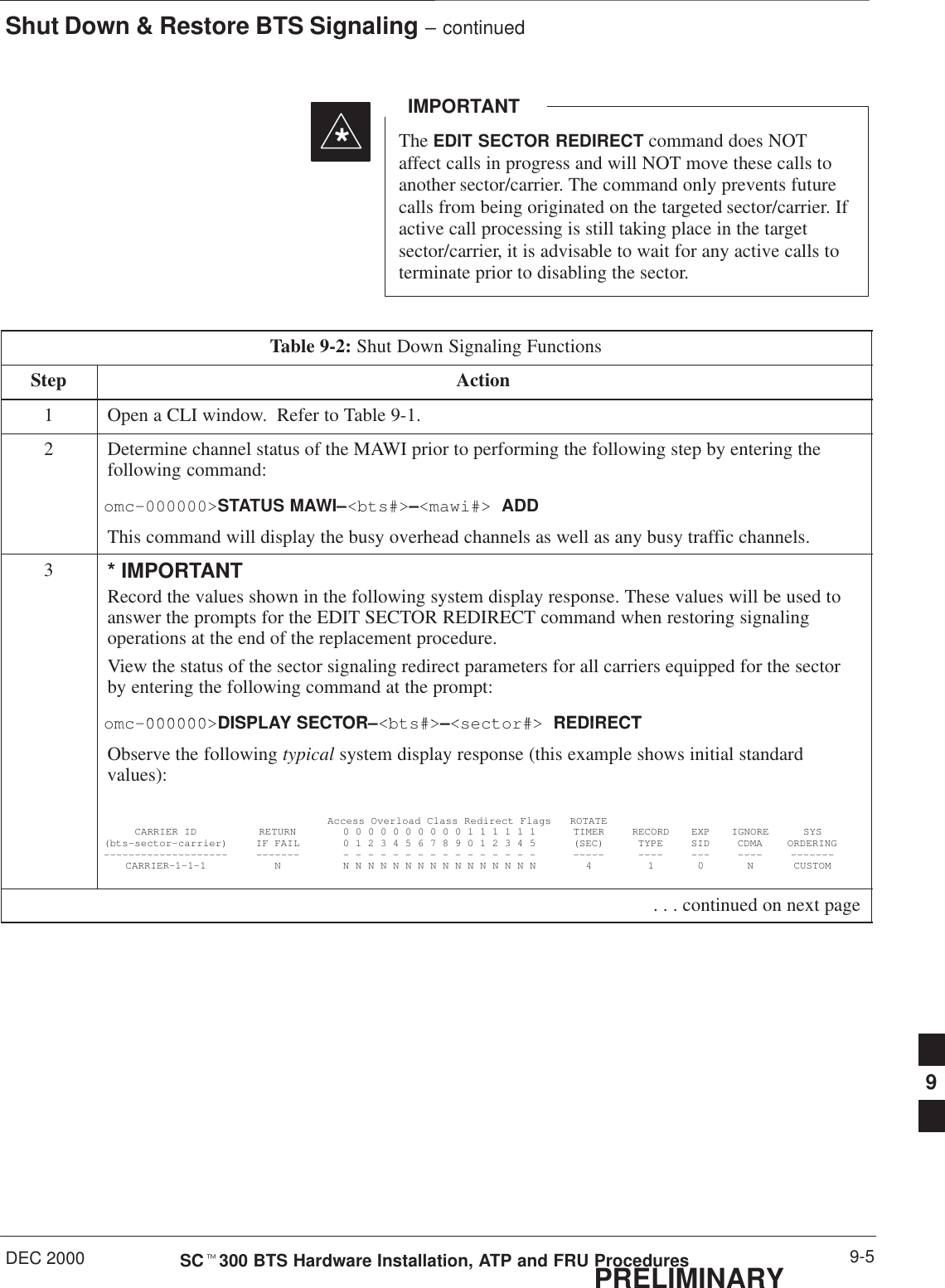
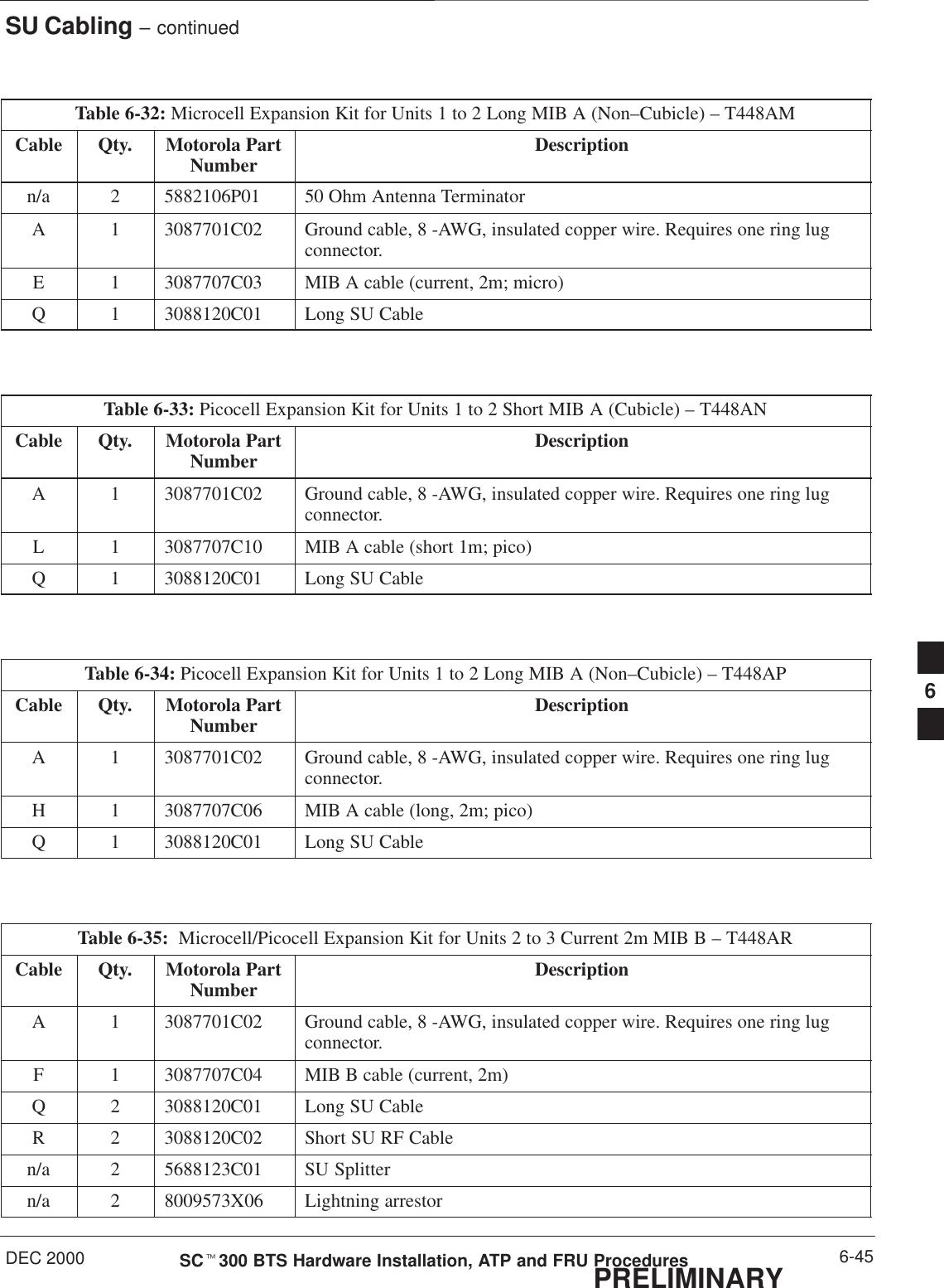
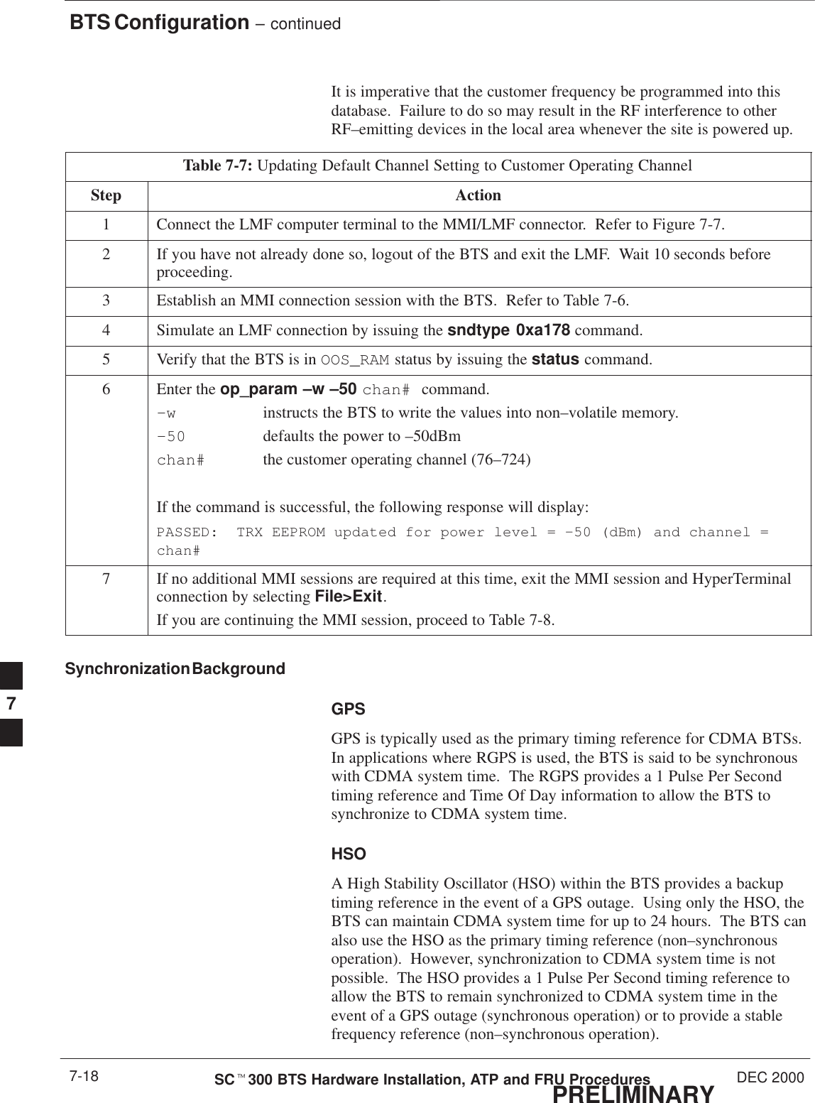
![Shut Down & Restore BTS Signaling – continuedPRELIMINARYSCt300 BTS Hardware Installation, ATP and FRU Procedures DEC 20009-6Table 9-2: Shut Down Signaling FunctionsStep Action4NOTEThis step edits the redirect parameters so that the Global Service Redirect Message broadcast onthe paging channel redirects all subscribers away from the sector with the failed equipment andonto a different system.Enter the following command at the prompt:omc–000000>EDIT SECTOR–<bts#>–<sector#> REDIRECT !The system will prompt you to enter each command parameter value one at a time. Answer theprompts in the following order:<accolc0> enter Y, <accolc1> enter Y, ... <accolc15> enter Y(All Access Overload Classes must be set to yes to ensure that all subscribers are redirected.)<returniffail> , enter N(Must be set to no to ensure that subscribers do not return if redirect is unsuccessful.)<recordtype> , enter 4 (A value of four redirects subscribers to a JTACS analog site )(A value of four redirects subscribers to a JTACS analog site.)<expectedsid> , enter 13 (Use the Area ID the subscriber units should expect to find on the system they are beingredirected to. This example uses 13.)<ignorecdma> , enter Y<sysordering> , enter CUSTOM (System ordering value does not matter because it is not used in JTACS systems.)<rotatetimer> , enter 4 (Call processing continuously rotates, circular right–shifts, the Y/N values of Access OverloadClass Redirect Flags 0 to 9. Values are shifted one flag at the end of the timer period; then timerre–starts. Valid values are 0–255; 4 is default.)The system will display the command that will be sent. Verify the command syntax.omc–000000>Accept [yes/no]?Enter Y to accept the command.5View the status of the sector signaling redirect parameters to verify that the sector is ready formaintenance.omc–000000>DISPLAY SECTOR–<bts#>–<sector#> REDIRECTEnsure that the values in the system display response match the values input in step 4 (seeexample below).Access Overload Class Redirect Flags ROTATECARRIER ID RETURN 0 0 0 0 0 0 0 0 0 0 1 1 1 1 1 1 TIMER RECORD EXP IGNORE SYS(bts–sector–carrier) IF FAIL 0 1 2 3 4 5 6 7 8 9 0 1 2 3 4 5 (SEC) TYPE SID CDMA ORDERING–––––––––––––––––––– ––––––– – – – – – – – – – – – – – – – – ––––– –––– –––– ––– ––––––––CARRIER–1–1–1 N Y Y Y Y Y Y Y Y Y Y Y Y Y Y Y Y 4 4 13 Y CUSTOM . . . continued on next page9](https://usermanual.wiki/Nokia-Solutions-and-Networks/T6AQ2.2-of-2/User-Guide-141660-Page-158.png)
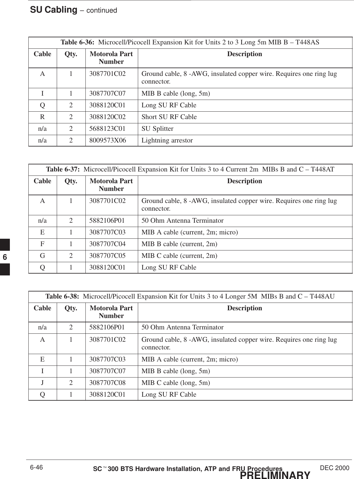
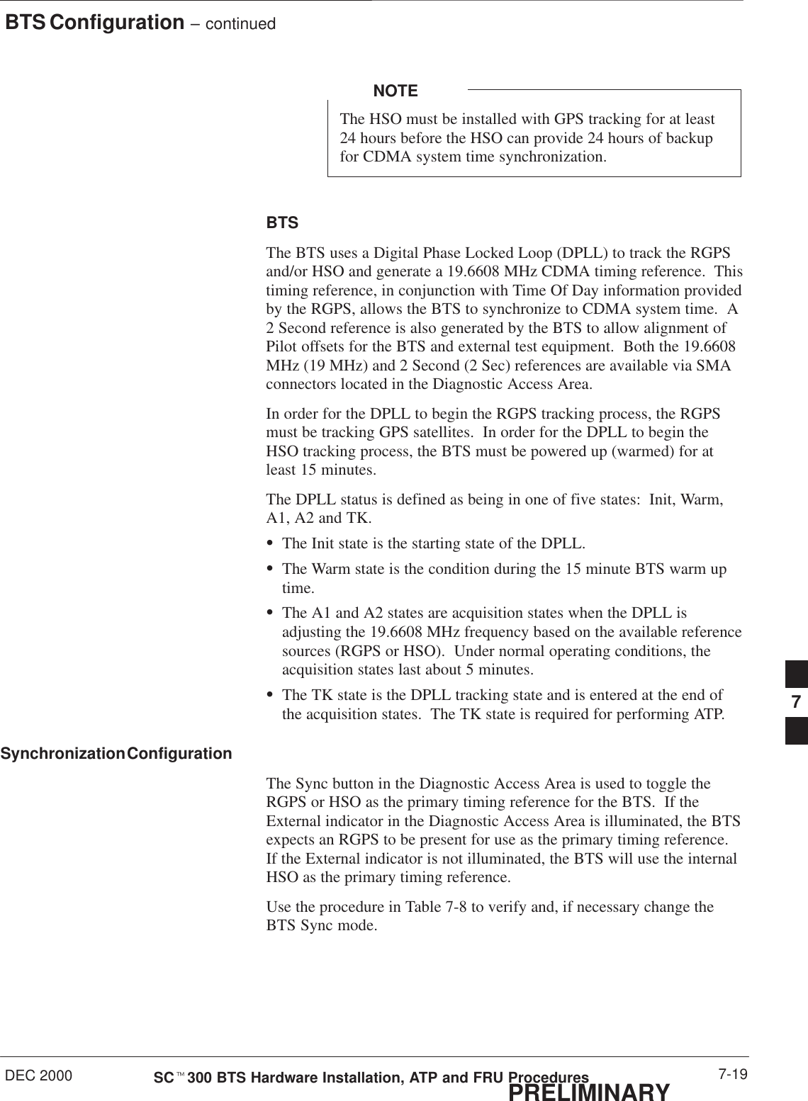
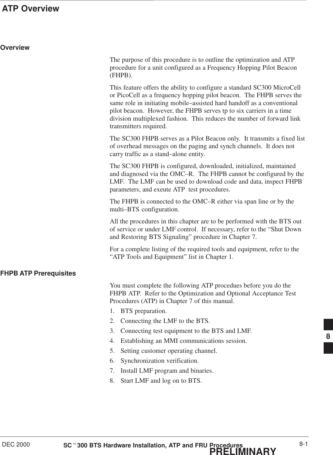
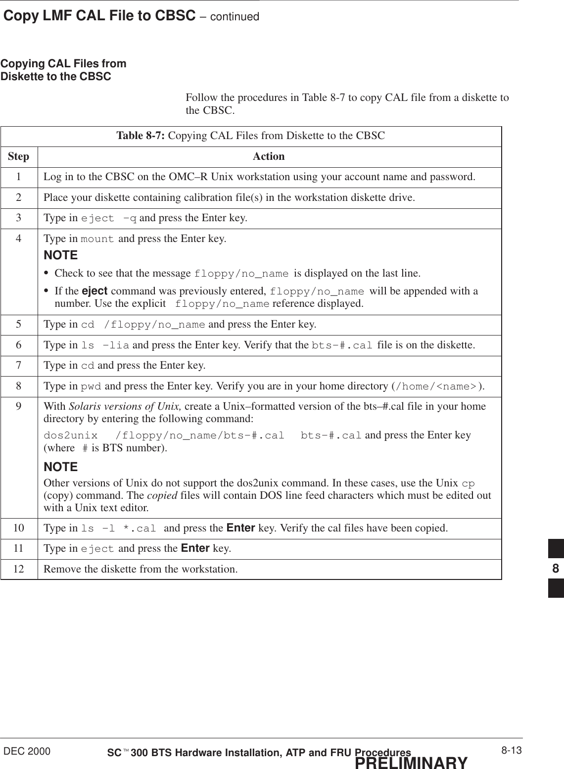
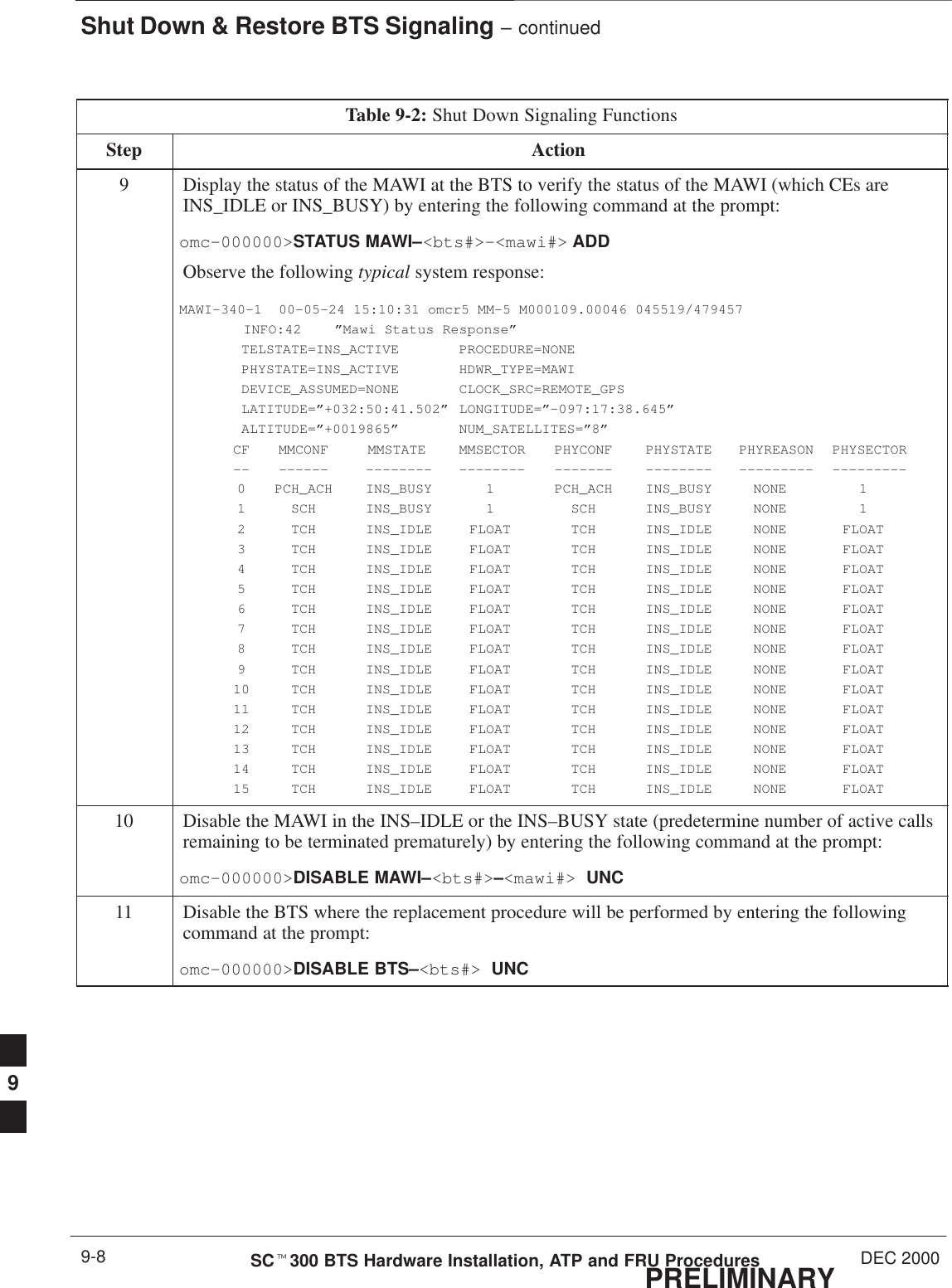
![Shut Down & Restore BTS Signaling – continuedDEC 2000 9-7SCt300 BTS Hardware Installation, ATP and FRU ProceduresPRELIMINARYTable 9-2: Shut Down Signaling FunctionsStep Action6View the existing congestion control parameters for all carriers equipped for the sector by enteringthe following command at the prompt:omc–000000>DISPLAY SECTOR–<bts#>–<sector#> CONGESTCONFObserve the following typical system display response:CARRIER NEWCALL REG AGG(bts#–sector#–carrier#) SET ALARMFLAG ALARMFLAG ALARMFLAG ANALOGREDIRECT GLOBALREDIRECT––––––––––––––––––––––– ––– ––––––––– –––––––––– –––––––––– –––––––––––––– ––––––––––––––340–1–4 1 ENABLE ENABLE ENABLE DISABLE DISABLE7NOTEIn this step, you will change the value of the Global Service Redirection Flag(GLOBALREDIRECT) in the congestion control parameters so that the Global Service RedirectMessage is broadcast on the sector paging channel.Enter the following command at the prompt:omc–000000>EDIT SECTOR–<bts#>–<sector#> CONGESTCONF !The system will prompt you to enter each control parameter value one at a time. Skip through theprompts until you get to the following:<globalredirect> , enter ENABLE <globalredirect> , enter ENABLE (This will force the Global Service Redirect Message to be broadcast on the sector pagingchannel.)The system will display the values of the control parameters. Verify that only theGLOBALREDIRECT value changed.omc–000000>Accept [yes/no]?Enter Y to accept the change.Now the Global Service Redirection Message is sent over the sector paging channels. Allsubscribers are redirected away from the sector and onto a different system. This effectively shutsdown the sector.8Display the status of the MAWI at the BTS by entering the following command at the prompt:omc–000000>DISPLAY BTS–<bts#> STATUSObserve the following typical system response for the entry of: DISPLAY BTS – 340 STATUSDEVSYNCConfig Calibration Calibration ISO RELATEDDEVICE CBSC STATUS Data Data Sync STATE–––––––––––––––––– –––– –––––– –––– –––– ––––––– ––––––––––––BTS–340 1 INS n/a n/a UNLOCKED UNLOCKEDBTSSPAN–340–1 1 INS n/a n/a n/a n/aBTSLINK–340–1 1 INS n/a n/a n/a n/aLPA–340–1 1 OOS_PARENT n/a n/a n/a n/aMDM–340–1 1 PRECUT n/a n/a n/a n/aMAWI–340–1 1 INS GOOD GOOD GOOD KEYED . . . continued on next page9](https://usermanual.wiki/Nokia-Solutions-and-Networks/T6AQ2.2-of-2/User-Guide-141660-Page-159.png)
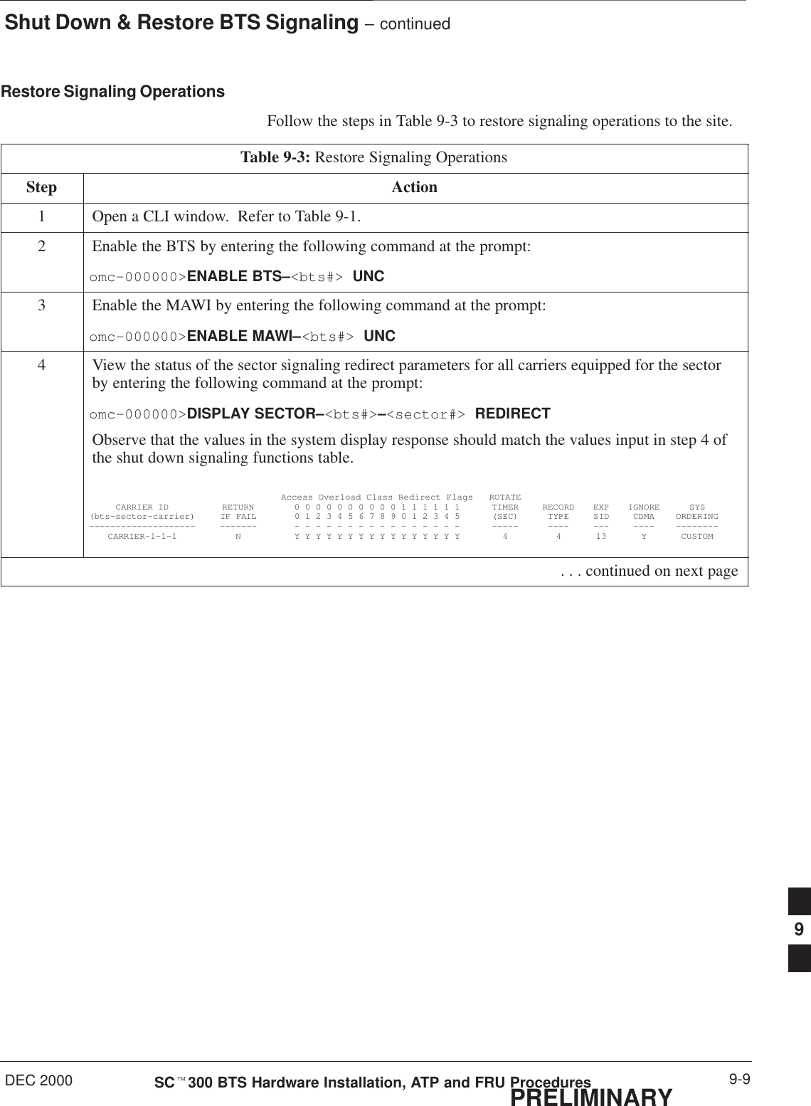
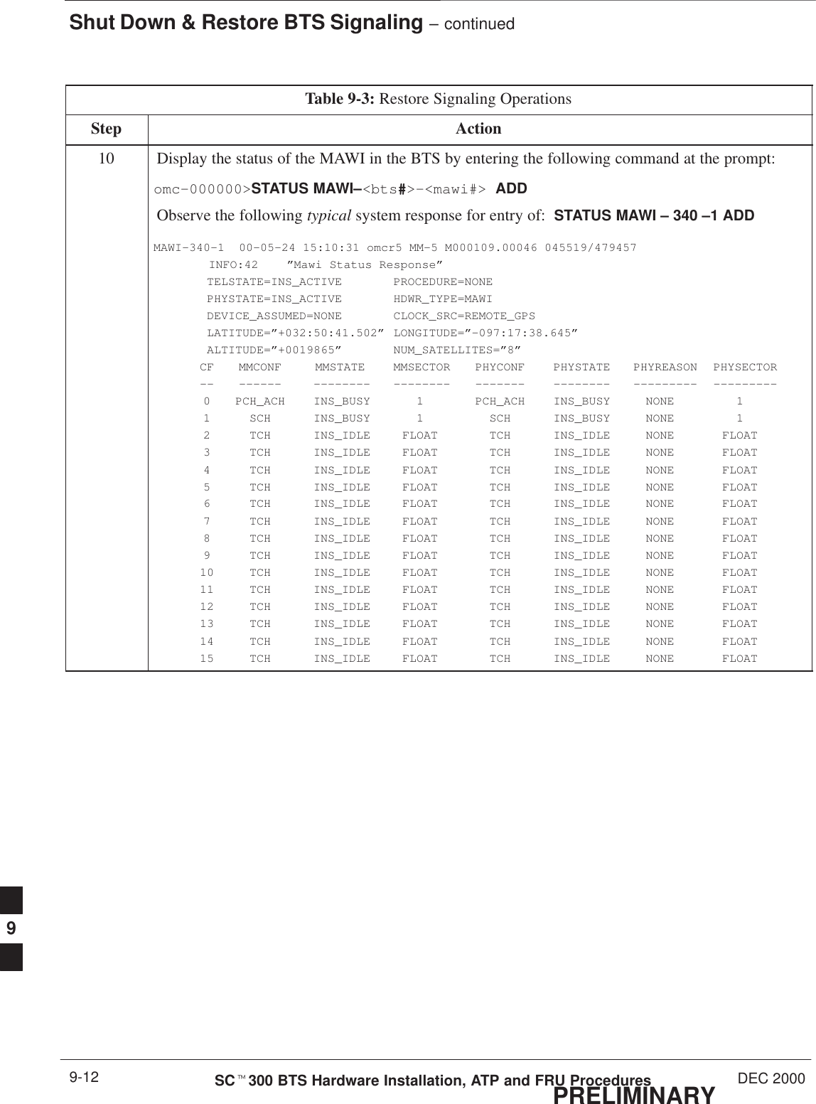
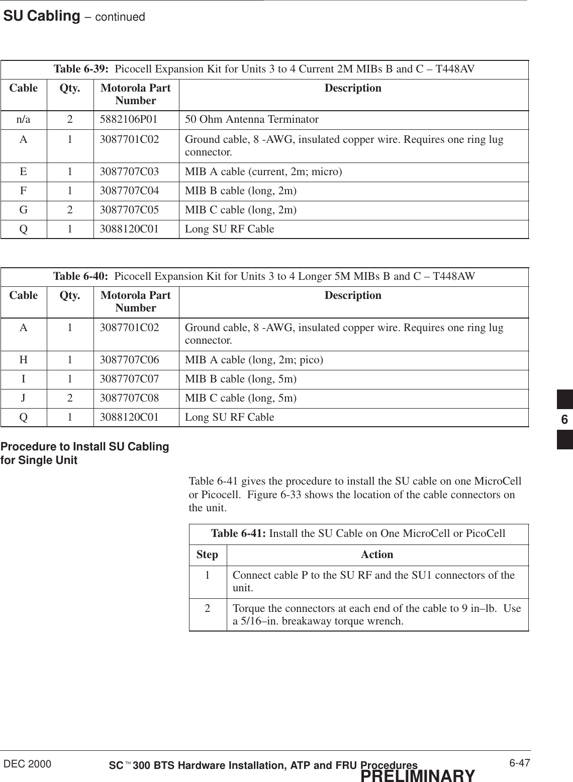
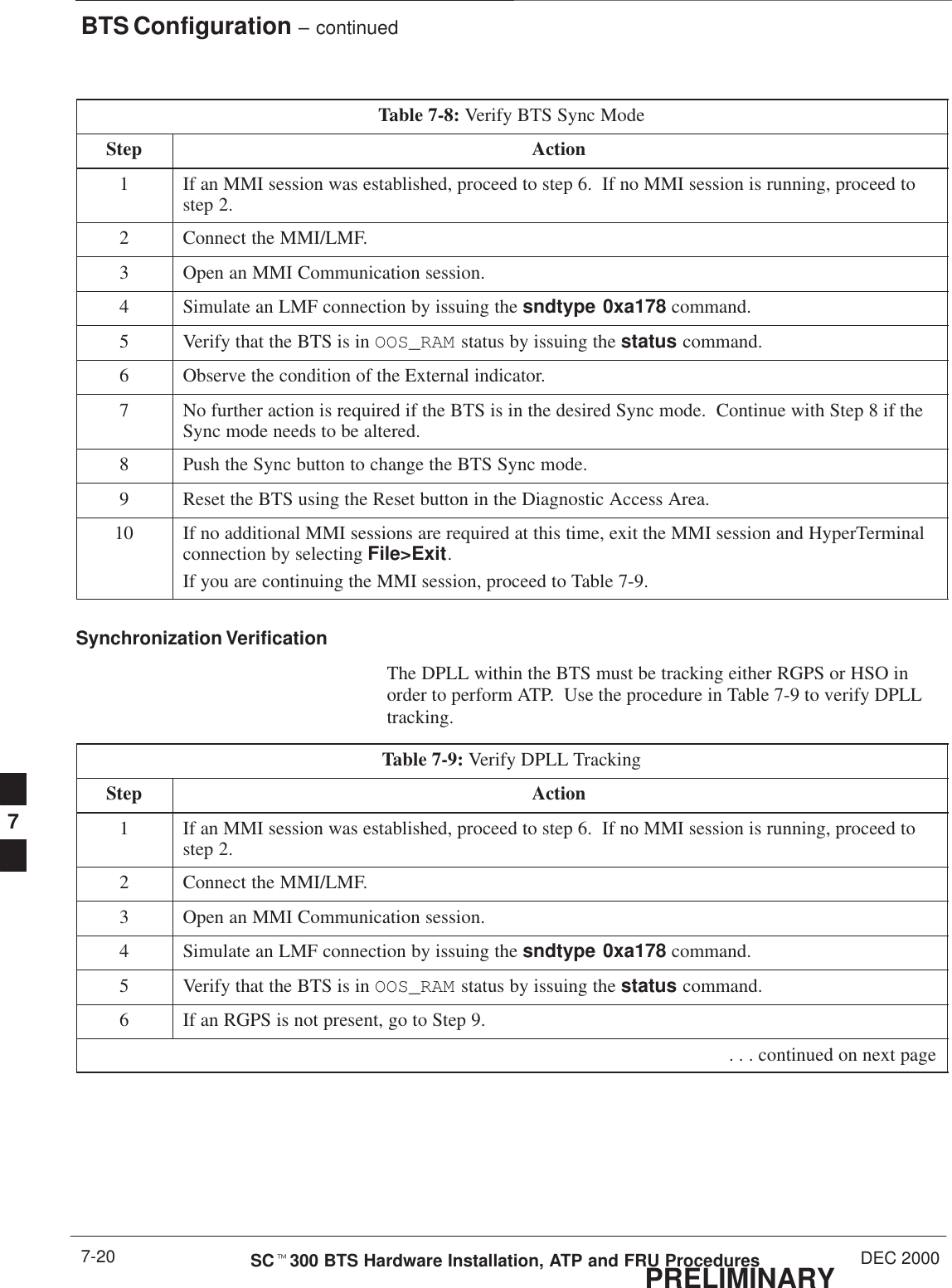
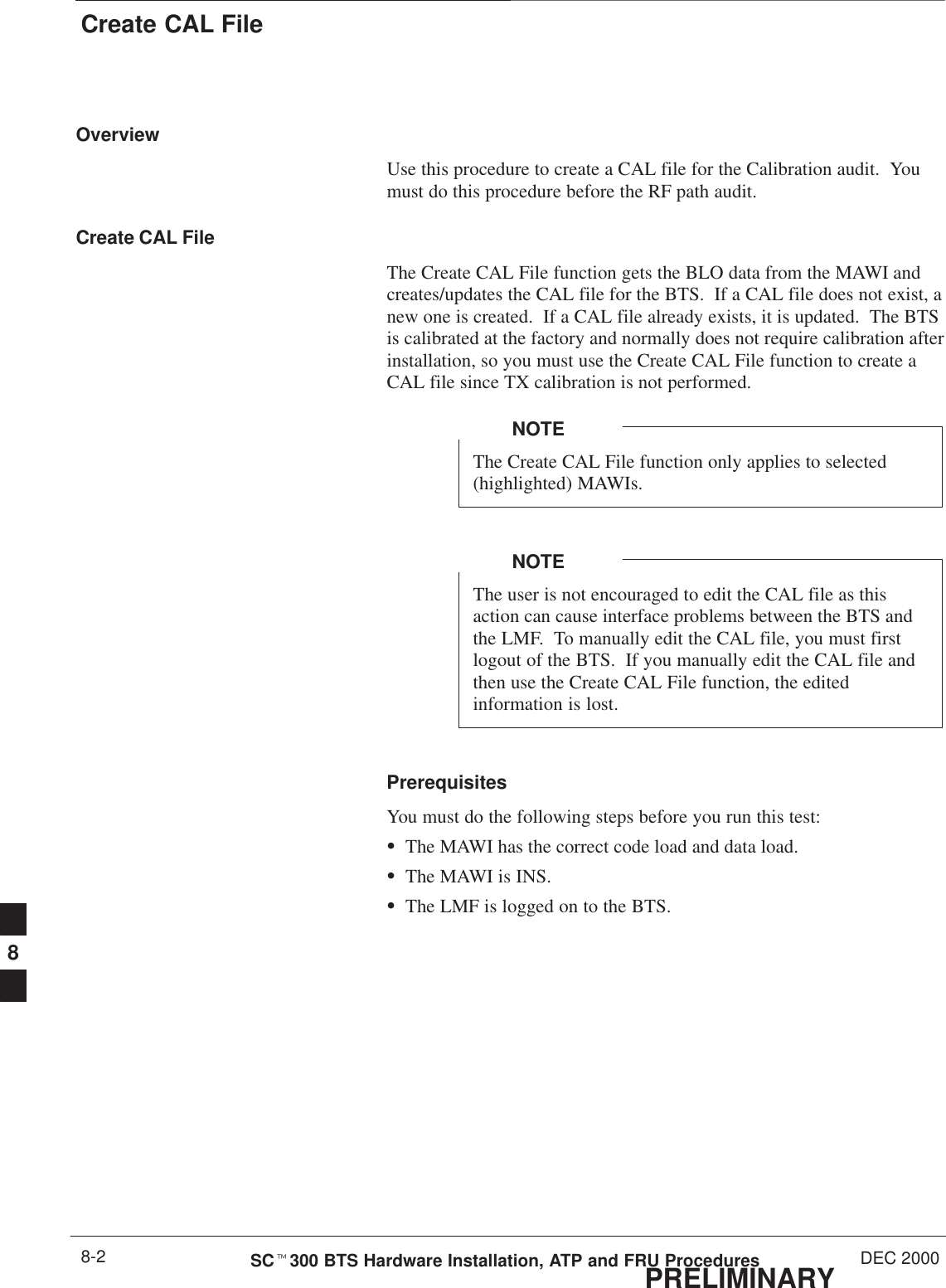
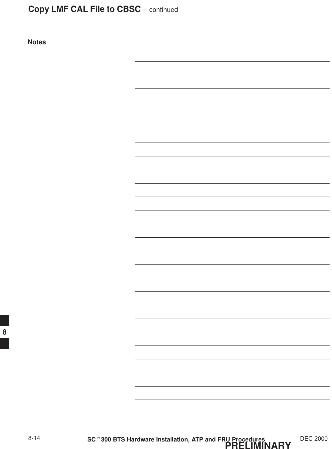
![Shut Down & Restore BTS Signaling – continuedPRELIMINARYSCt300 BTS Hardware Installation, ATP and FRU Procedures DEC 20009-10Table 9-3: Restore Signaling OperationsStep Action5* IMPORTANTIn this step, use the values recorded in step 3 of the shut down signaling functions table to answerthe prompts for the EDIT SECTOR REDIRECT command; except for record type enter 2.NOTEThis step shows the entry of initial standard values which is consistent with the original example;except record type must be 2. Your entries may be different.Restore the values of all redirect parameters by entering the following command at the prompt:omc–000000>EDIT SECTOR–<bts#>–<sector#> REDIRECT !The system will prompt you to enter each command parameter one at a time. Answer the promptsin the following order (Note that the following specified values are consistent with the originalexample. Yours may be different):<accolc0> Enter N, <accolc1> Enter N, ... <accolc15> enter N<returniffail> , enter N<recordtype> , enter 2<expectedsid>enter 0<expectedsid> , enter 0<ignorecdma> , enter N<sysordering> , enter CUSTOM<rotatetimer> , enter 4The system will display the command that will be sent. Verify the command syntax.omc–000000>Accept [yes/no]?Enter Y to accept the command.6View the status of the sector signaling redirect parameters to verify that the sector is ready formaintenance.omc–000000>DISPLAY SECTOR–<bts#>–<sector#> REDIRECTEnsure that the values in the system display response match the values input by the operator instep 5 (see example below).Access Overload Class Redirect Flags ROTATECARRIER ID RETURN 0 0 0 0 0 0 0 0 0 0 1 1 1 1 1 1 TIMER RECORD EXP IGNORE SYS(bts–sector–carrier) IF FAIL 0 1 2 3 4 5 6 7 8 9 0 1 2 3 4 5 (SEC) TYPE SID CDMA ORDERING–––––––––––––––––––– ––––––– – – – – – – – – – – – – – – – – ––––– –––– ––– –––– ––––––––CARRIER–1–1–1 N N N N N N N N N N N N N N N N N 4 2 0 N CUSTOM . . . continued on next page9](https://usermanual.wiki/Nokia-Solutions-and-Networks/T6AQ2.2-of-2/User-Guide-141660-Page-162.png)
![Shut Down & Restore BTS Signaling – continuedDEC 2000 9-11SCt300 BTS Hardware Installation, ATP and FRU ProceduresPRELIMINARYTable 9-3: Restore Signaling OperationsStep Action7View the congestion control parameters for all carriers equipped for the sector by entering thefollowing command at the prompt:omc–000000>DISPLAY SECTOR–<bts#>–<sector#> CONGESTCONFObserve the following typical system display response:CARRIER NEWCALL REG AGG(bts#–sector#–carrier#) SET ALARMFLAG ALARMFLAG ALARMFLAG ANALOGREDIRECT GLOBALREDIRECT––––––––––––––––––––––– ––– ––––––––– ––––––––– ––––––––– –––––––––––––– ––––––––––––––340–1–4 1 ENABLE ENABLE ENABLE DISABLE ENABLE8NOTEIn this step, you will change the value of the Global Service Redirection Flag(GLOBALREDIRECT) in the congestion control parameters so that the Global Service RedirectMessage is only broadcast on the sector paging channel when there is traffic congestion in thesector.Enter the following command at the prompt:omc–000000>EDIT SECTOR–<bts#>–<sector#> CONGESTCONF !The system will prompt you to enter each control parameter value one at a time. Skip through theprompts until you get to the following:prompts until you get to the following:<globalredirect> , enter DISABLE (This will revert the Global Service Redirect Message to congestion control.)The system will display the values of the control parameters. Verify that only theGLOBALREDIRECT value changed.omc–000000>Accept [yes/no]?Enter Y to accept the change.Now the Global Service Redirection Message will only be sent over the sector paging channelswhen there is traffic congestion in the sector.9Display the status of the MAWI at the BTS by entering the following command at the prompt:omc–000000>DISPLAY BTS–<bts#> STATUSObserve the following typical system response:DEVSYNCConfig Calibration Calibration ISO RELATEDDEVICE CBSC STATUS Data Data Sync STATE–––––––––––––––––– –––– –––––– –––– –––– ––––––– ––––––––––––BTS–340 1 INS n/a n/a UNLOCKED UNLOCKEDBTSSPAN–340–1 1 INS n/a n/a n/a n/aBTSLINK–340–1 1 INS n/a n/a n/a n/aLPA–340–1 1 OOS_PARENT n/a n/a n/a n/aMDM–340–1 1 PRECUT n/a n/a n/a n/aMAWI–340–1 1 INS GOOD GOOD GOOD KEYED . . . continued on next page9](https://usermanual.wiki/Nokia-Solutions-and-Networks/T6AQ2.2-of-2/User-Guide-141660-Page-163.png)