Nokia Solutions and Networks T6AQ2 SC300 Microcell 1.9GHz User Manual frtcov
Nokia Solutions and Networks SC300 Microcell 1.9GHz frtcov
Contents
- 1. 1 of 2
- 2. 2 of 2
2 of 2

DEC 2000 SCt300 BTS Hardware Installation, ATP and FRU Procedures
PRELIMINARY
Chapter 6: Installing the Unit and Installation Check Off List
Table of Contents
Unit Installation Overview 6-1. . . . . . . . . . . . . . . . . . . . . . . . . . . . . . . . . . . . . . . . .
Overview 6-1. . . . . . . . . . . . . . . . . . . . . . . . . . . . . . . . . . . . . . . . . . . . . . . .
Unit Installation Procedure Order 6-1. . . . . . . . . . . . . . . . . . . . . . . . . . . . .
Connector Locations 6-2. . . . . . . . . . . . . . . . . . . . . . . . . . . . . . . . . . . . . . . . . . . . . .
Connector Locations 6-2. . . . . . . . . . . . . . . . . . . . . . . . . . . . . . . . . . . . . . .
Attaching Back Fin Cover to Unit 6-5. . . . . . . . . . . . . . . . . . . . . . . . . . . . . . . . . . .
Objective 6-5. . . . . . . . . . . . . . . . . . . . . . . . . . . . . . . . . . . . . . . . . . . . . . . .
When to Use the Fin Covers 6-5. . . . . . . . . . . . . . . . . . . . . . . . . . . . . . . . .
Procedure 6-5. . . . . . . . . . . . . . . . . . . . . . . . . . . . . . . . . . . . . . . . . . . . . . . .
Attaching Optional Installation Handles to the Unit 6-6. . . . . . . . . . . . . . . . . . . . .
Objective 6-6. . . . . . . . . . . . . . . . . . . . . . . . . . . . . . . . . . . . . . . . . . . . . . . .
Required Tools and Materials 6-6. . . . . . . . . . . . . . . . . . . . . . . . . . . . . . . .
Procedure to Attach the Installation Handles to the Unit 6-6. . . . . . . . . . .
Attaching Unit to Mounting Bracket 6-8. . . . . . . . . . . . . . . . . . . . . . . . . . . . . . . . .
Objective 6-8. . . . . . . . . . . . . . . . . . . . . . . . . . . . . . . . . . . . . . . . . . . . . . . .
Background 6-8. . . . . . . . . . . . . . . . . . . . . . . . . . . . . . . . . . . . . . . . . . . . . .
Tools and Materials 6-8. . . . . . . . . . . . . . . . . . . . . . . . . . . . . . . . . . . . . . . .
Procedure to Attach the Unit to the Mounting Bracket 6-9. . . . . . . . . . . . .
Earth Ground Cabling 6-11. . . . . . . . . . . . . . . . . . . . . . . . . . . . . . . . . . . . . . . . . . . . .
Objective 6-11. . . . . . . . . . . . . . . . . . . . . . . . . . . . . . . . . . . . . . . . . . . . . . . .
Other Grounding Considerations 6-11. . . . . . . . . . . . . . . . . . . . . . . . . . . . . .
Cable Description 6-11. . . . . . . . . . . . . . . . . . . . . . . . . . . . . . . . . . . . . . . . .
Tools and Materials 6-11. . . . . . . . . . . . . . . . . . . . . . . . . . . . . . . . . . . . . . . .
Attaching Front Fin Cover to Unit 6-14. . . . . . . . . . . . . . . . . . . . . . . . . . . . . . . . . . .
Objective 6-14. . . . . . . . . . . . . . . . . . . . . . . . . . . . . . . . . . . . . . . . . . . . . . . .
When to Use the Fin Covers 6-14. . . . . . . . . . . . . . . . . . . . . . . . . . . . . . . . .
Procedure 6-14. . . . . . . . . . . . . . . . . . . . . . . . . . . . . . . . . . . . . . . . . . . . . . . .
Attaching the Site I/O Junction Box to the Unit 6-15. . . . . . . . . . . . . . . . . . . . . . . .
Objective 6-15. . . . . . . . . . . . . . . . . . . . . . . . . . . . . . . . . . . . . . . . . . . . . . . .
Required Tools and Materials 6-15. . . . . . . . . . . . . . . . . . . . . . . . . . . . . . . .
Procedure to Attach the Site I/O Junction Box to the Unit 6-15. . . . . . . . . .
Procedure to Attach a Site I/O Cap to the Unit (optional) 6-16. . . . . . . . . .
6

Table of Contents – continued
PRELIMINARY
SCt300 BTS Hardware Installation, ATP and FRU Procedures DEC 2000
Attaching the Short Duration Battery to the Unit (optional) 6-17. . . . . . . . . . . . . . .
Objective 6-17. . . . . . . . . . . . . . . . . . . . . . . . . . . . . . . . . . . . . . . . . . . . . . . .
Required Tools and Materials 6-17. . . . . . . . . . . . . . . . . . . . . . . . . . . . . . . .
Procedure to Attach the Battery to the Unit 6-17. . . . . . . . . . . . . . . . . . . . .
Short Duration Battery Cabling 6-19. . . . . . . . . . . . . . . . . . . . . . . . . . . . . . . . . . . . .
Objective 6-19. . . . . . . . . . . . . . . . . . . . . . . . . . . . . . . . . . . . . . . . . . . . . . . .
Battery Cable 6-19. . . . . . . . . . . . . . . . . . . . . . . . . . . . . . . . . . . . . . . . . . . . .
Procedure 6-19. . . . . . . . . . . . . . . . . . . . . . . . . . . . . . . . . . . . . . . . . . . . . . . .
AC Power Cabling 6-21. . . . . . . . . . . . . . . . . . . . . . . . . . . . . . . . . . . . . . . . . . . . . . .
Objective 6-21. . . . . . . . . . . . . . . . . . . . . . . . . . . . . . . . . . . . . . . . . . . . . . . .
Cable Description 6-21. . . . . . . . . . . . . . . . . . . . . . . . . . . . . . . . . . . . . . . . .
Power Cable and Connector Signal Information 6-21. . . . . . . . . . . . . . . . . .
Procedure 6-21. . . . . . . . . . . . . . . . . . . . . . . . . . . . . . . . . . . . . . . . . . . . . . . .
DC Power Cabling 6-23. . . . . . . . . . . . . . . . . . . . . . . . . . . . . . . . . . . . . . . . . . . . . . .
Objective 6-23. . . . . . . . . . . . . . . . . . . . . . . . . . . . . . . . . . . . . . . . . . . . . . . .
Cable Decription 6-23. . . . . . . . . . . . . . . . . . . . . . . . . . . . . . . . . . . . . . . . . .
Power Cable and Connector Signal Information 6-23. . . . . . . . . . . . . . . . . .
Procedure 6-23. . . . . . . . . . . . . . . . . . . . . . . . . . . . . . . . . . . . . . . . . . . . . . . .
Antenna Cabling for Sites Equipped With
Customer–Supplied Site I/O Interface 6-25. . . . . . . . . . . . . . . . . . . . . . . . . . . . . . . .
Objective 6-25. . . . . . . . . . . . . . . . . . . . . . . . . . . . . . . . . . . . . . . . . . . . . . . .
Cable Labels 6-25. . . . . . . . . . . . . . . . . . . . . . . . . . . . . . . . . . . . . . . . . . . . .
Cable Descriptions 6-25. . . . . . . . . . . . . . . . . . . . . . . . . . . . . . . . . . . . . . . . .
Procedure 6-25. . . . . . . . . . . . . . . . . . . . . . . . . . . . . . . . . . . . . . . . . . . . . . . .
Antenna Cabling for Sites Equipped with Optional Primary Surge Suppressor 6-30
Objective 6-30. . . . . . . . . . . . . . . . . . . . . . . . . . . . . . . . . . . . . . . . . . . . . . . .
Cable Labels 6-30. . . . . . . . . . . . . . . . . . . . . . . . . . . . . . . . . . . . . . . . . . . . .
Cable Descriptions 6-30. . . . . . . . . . . . . . . . . . . . . . . . . . . . . . . . . . . . . . . . .
Procedure 6-30. . . . . . . . . . . . . . . . . . . . . . . . . . . . . . . . . . . . . . . . . . . . . . . .
MIB Cabling for Multi–Unit Configurations 6-38. . . . . . . . . . . . . . . . . . . . . . . . . . .
Overview 6-38. . . . . . . . . . . . . . . . . . . . . . . . . . . . . . . . . . . . . . . . . . . . . . . .
Cable Labels 6-38. . . . . . . . . . . . . . . . . . . . . . . . . . . . . . . . . . . . . . . . . . . . .
Tools and Equipment 6-38. . . . . . . . . . . . . . . . . . . . . . . . . . . . . . . . . . . . . . .
Procedure 6-41. . . . . . . . . . . . . . . . . . . . . . . . . . . . . . . . . . . . . . . . . . . . . . . .
SU Cabling 6-44. . . . . . . . . . . . . . . . . . . . . . . . . . . . . . . . . . . . . . . . . . . . . . . . . . . . .
Objective 6-44. . . . . . . . . . . . . . . . . . . . . . . . . . . . . . . . . . . . . . . . . . . . . . . .
Cable Labels 6-44. . . . . . . . . . . . . . . . . . . . . . . . . . . . . . . . . . . . . . . . . . . . .
Tools and Equipment 6-44. . . . . . . . . . . . . . . . . . . . . . . . . . . . . . . . . . . . . . .
Procedure to Install SU Cabling for Single Unit 6-47. . . . . . . . . . . . . . . . . .
SU Cabling for Multi–Unit Configurations 6-48. . . . . . . . . . . . . . . . . . . . . .
Terminating Unused Connections 6-51. . . . . . . . . . . . . . . . . . . . . . . . . . . . . . . . . . . .
Objective 6-51. . . . . . . . . . . . . . . . . . . . . . . . . . . . . . . . . . . . . . . . . . . . . . . .
Termination List (MicroCell) 6-51. . . . . . . . . . . . . . . . . . . . . . . . . . . . . . . .
Termination List (PicoCell) 6-51. . . . . . . . . . . . . . . . . . . . . . . . . . . . . . . . . .
Procedure 6-51. . . . . . . . . . . . . . . . . . . . . . . . . . . . . . . . . . . . . . . . . . . . . . . .
6

Table of Contents – continued
DEC 2000 SCt300 BTS Hardware Installation, ATP and FRU Procedures
PRELIMINARY
Powering on Unit and Mounting the Solar Cover 6-52. . . . . . . . . . . . . . . . . . . . . . .
Objective 6-52. . . . . . . . . . . . . . . . . . . . . . . . . . . . . . . . . . . . . . . . . . . . . . . .
You May Want to Wait 6-52. . . . . . . . . . . . . . . . . . . . . . . . . . . . . . . . . . . . . .
Tools Required 6-52. . . . . . . . . . . . . . . . . . . . . . . . . . . . . . . . . . . . . . . . . . . .
Procedure to Power On Unit and Mount Solar Cover 6-52. . . . . . . . . . . . . .
Procedure to Power On Surge Suppressor, Unit and Mount Solar Cover 6-52
Site Cleanup 6-56. . . . . . . . . . . . . . . . . . . . . . . . . . . . . . . . . . . . . . . . . . . . . . . . . . . .
Remove protective covering 6-56. . . . . . . . . . . . . . . . . . . . . . . . . . . . . . . . .
Lighting fixtures 6-56. . . . . . . . . . . . . . . . . . . . . . . . . . . . . . . . . . . . . . . . . .
Tools 6-56. . . . . . . . . . . . . . . . . . . . . . . . . . . . . . . . . . . . . . . . . . . . . . . . . . .
Materials 6-56. . . . . . . . . . . . . . . . . . . . . . . . . . . . . . . . . . . . . . . . . . . . . . . .
Remove debris 6-56. . . . . . . . . . . . . . . . . . . . . . . . . . . . . . . . . . . . . . . . . . . .
Environment 6-56. . . . . . . . . . . . . . . . . . . . . . . . . . . . . . . . . . . . . . . . . . . . .
Installation Completion Checklist 6-57. . . . . . . . . . . . . . . . . . . . . . . . . . . . . . . . . . .
Directions 6-57. . . . . . . . . . . . . . . . . . . . . . . . . . . . . . . . . . . . . . . . . . . . . . . .
Installation completion checklist 6-58. . . . . . . . . . . . . . . . . . . . . . . . . . . . . .
6

Table of Contents – continued
PRELIMINARY
SCt300 BTS Hardware Installation, ATP and FRU Procedures DEC 2000
Notes
6

Unit Installation Overview
DEC 2000 6-1
SCt300 BTS Hardware Installation, ATP and FRU Procedures
PRELIMINARY
Overview
This chapter provides the procedures for unit installation and cabling.
The site cabling has been installed and routed to the location of the BTS.
In this chapter, the cables will be attached to the unit(s). Cabling
installation will be repeated as necessary for each unit at the BTS.
This chapter provides the information and procedures to:
SAttach the unit to the mounting bracket
SAttach cables to the unit
SPower on the unit
SMount the solar covers
SComplete the installation completion checklist
Unit Installation Procedure
Order
The process of installing the unit requires that the following procedures
be completed in the order shown:
1. Attaching fin covers to the unit – optional
2. Attaching the installation handles to the unit
3. Attaching the unit to the mounting bracket and removing the
installation handles
4. Attaching earth ground cable and optional master ground cable.
5. Attaching the Site I/O junction box to the unit
6. Attaching the short duration battery (optional)
7. Attaching the AC input power or DC input power cable
8. Attaching antenna cable(s)
9. Attaching the MIB cables (optional)
10. Attaching the SU cables (optional)
11. Terminating unused connectors
12. Powering on the unit
13. Mounting solar cover
14. Cleaning up site
15. Filling out the installation completion checklist
6
Connector Locations
PRELIMINARY
SCt300 BTS Hardware Installation, ATP and FRU Procedures DEC 2000
6-2
Connector Locations
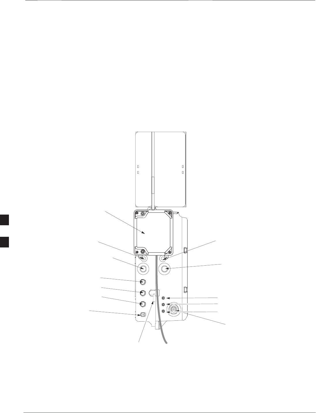
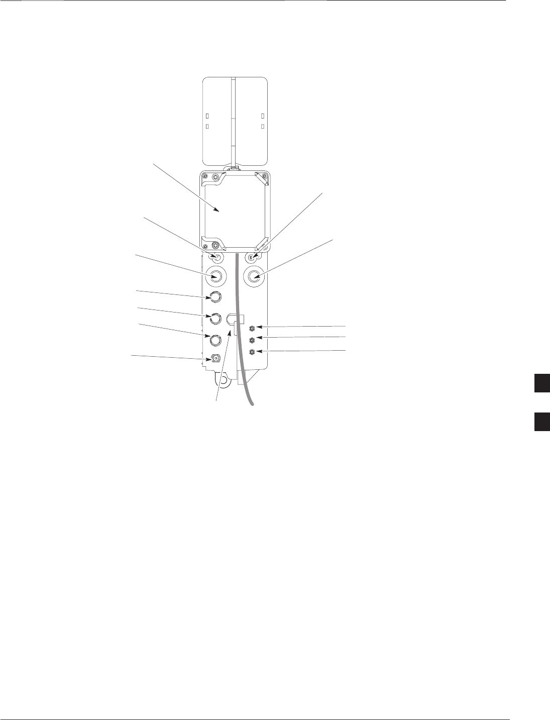
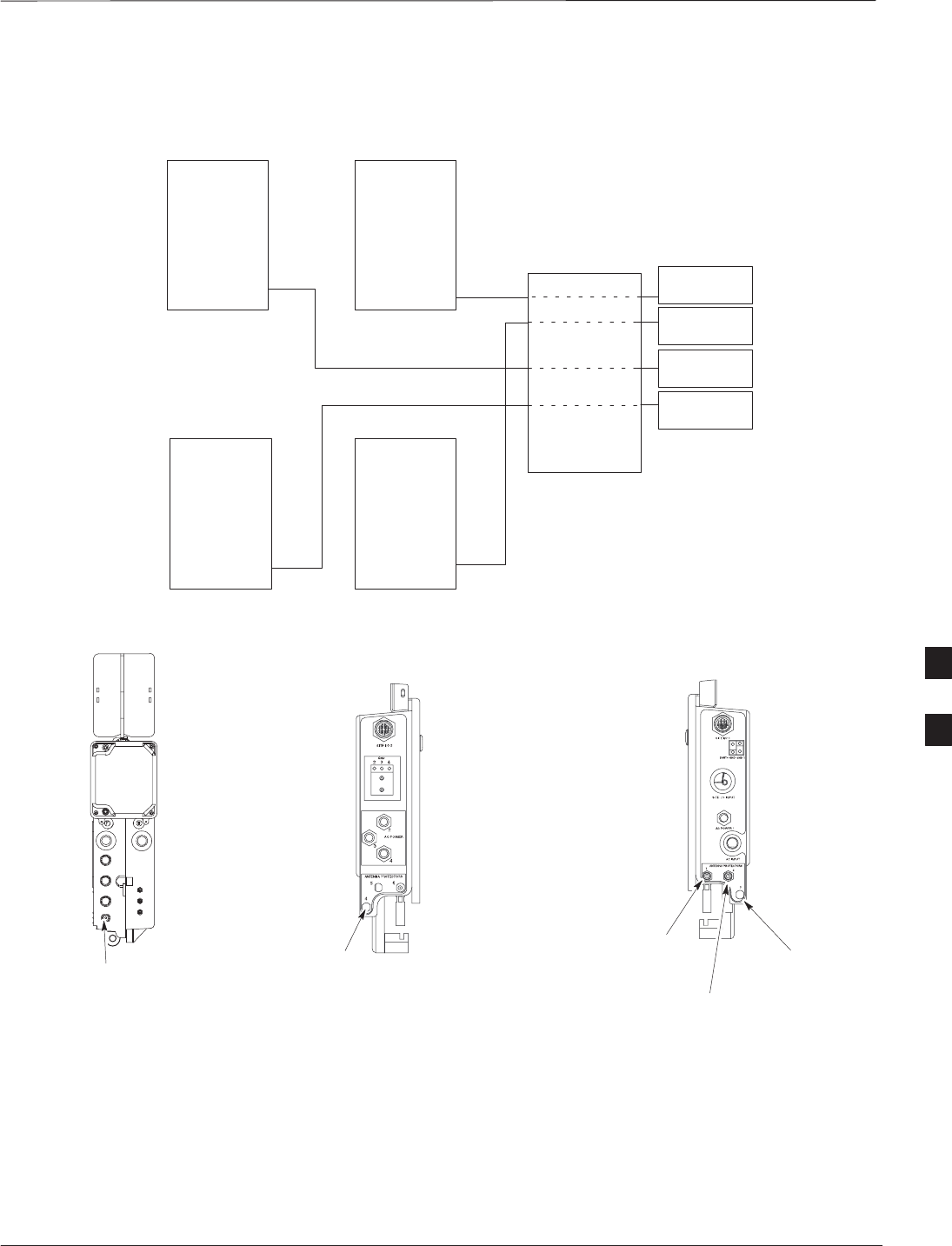
Figure 6-1, Figure 6-2, and Figure 6-3 show the location of the cable
connectors on the Microcell, Picocell, and Primary Surge Suppressor.
The system configuration determines which connectors are used.
Figure 6-1: Location of MicroCell Unit Connectors
SITE I/O
JUNCTION BOX
DC POWER BREAKER
DC INPUT
MIB C
ANTENNA B
AC INPUT
AC POWER BREAKER
SU RF
ANTENNA A
0169–O_IL.doc
TIE WRAP LOCATION
SU 2
SU 1
MIB B
MIB A
6
Connector Locations – continued
DEC 2000 6-3
SCt300 BTS Hardware Installation, ATP and FRU Procedures
PRELIMINARY
Figure 6-2: Location of PicoCell Unit Connectors
AC INPUT
AC POWER BREAKER
SITE I/O
JUNCTION BOX
DC POWER BREAKER
DC INPUT
ANTENNA A
0170–O_IL.doc
TIE WRAP LOCATION
MIB C
MIB B
MIB A SU RF
SU 2
SU 1
6
Connector Locations – continued
PRELIMINARY
SCt300 BTS Hardware Installation, ATP and FRU Procedures DEC 2000
6-4
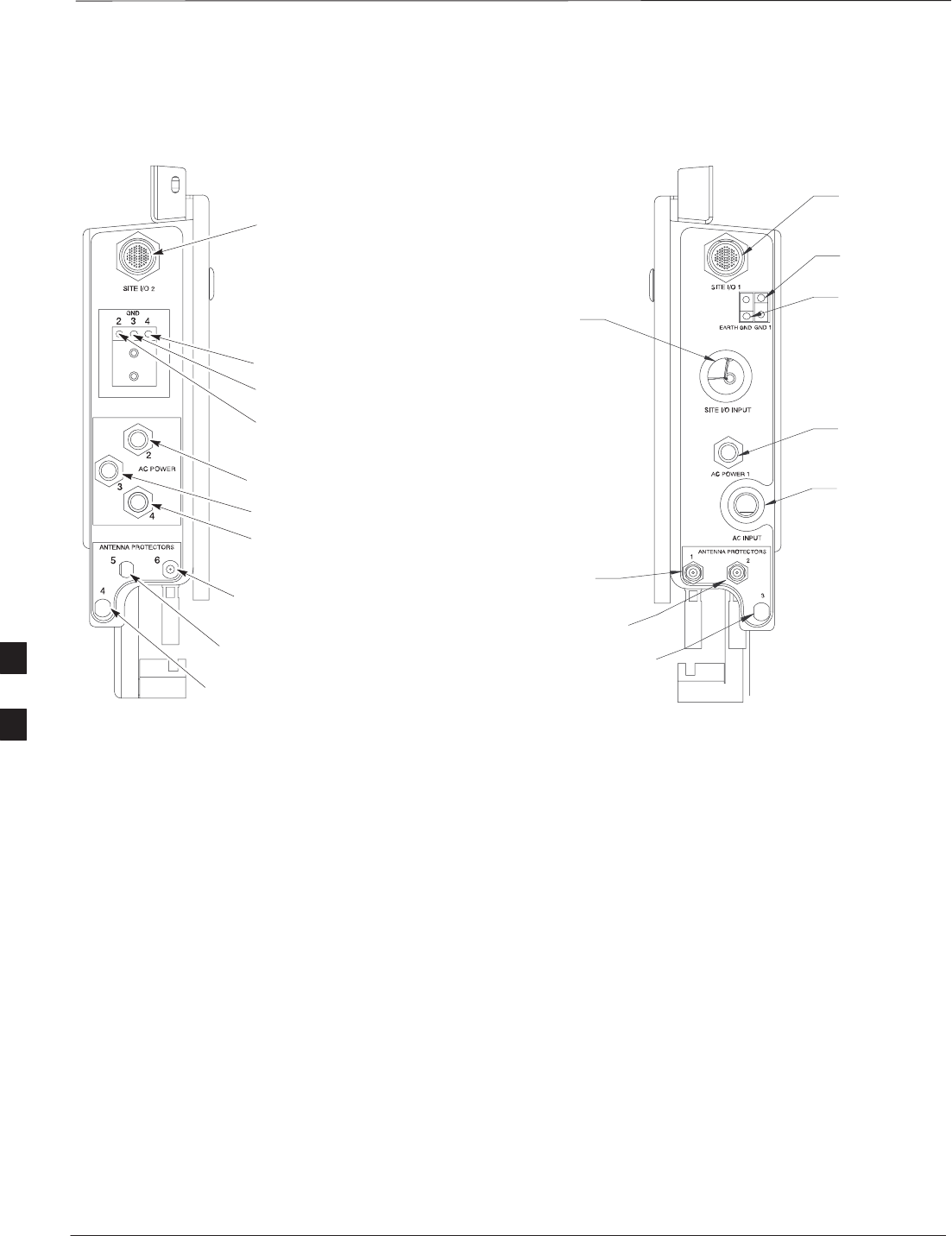
Figure 6-3: Location of Primary Surge Suppressor Connectors
SITE I/O 2
AC POWER 2
AC POWER 3
AC POWER 4
AC POWER 1
AC INPUT
(Conduit Hole)
SITE I/O INPUT
(Conduit Hole)
SITE I/O 1
ANTENNA PROTECTOR 2
ANTENNA PROTECTOR 1
LEFT SIDE RIGHT SIDE
GROUND 4
GROUND 3
GROUND 2
GROUND 1
EARTH
GROUND
ANTENNA PROTECTOR 3
(FOR FUTURE EXPANSION)
ANTENNA PROTECTOR 6
(FOR FUTURE EXPANSION)
ANTENNA PROTECTOR 5
(FOR FUTURE EXPANSION)
ANTENNA PROTECTOR 4
(FOR FUTURE EXPANSION)
6
Attaching Back Fin Cover to Unit
DEC 2000 6-5
SCt300 BTS Hardware Installation, ATP and FRU Procedures
PRELIMINARY
Objective
The objective of this procedure is to attach the back fin cover to the
PicoCell and MicroCell units. The front fin cover is mounted to the unit
after the unit is mounted to the mounting bracket.
When to Use the Fin Covers
The fin covers should always be used in an indoor application.
Procedure
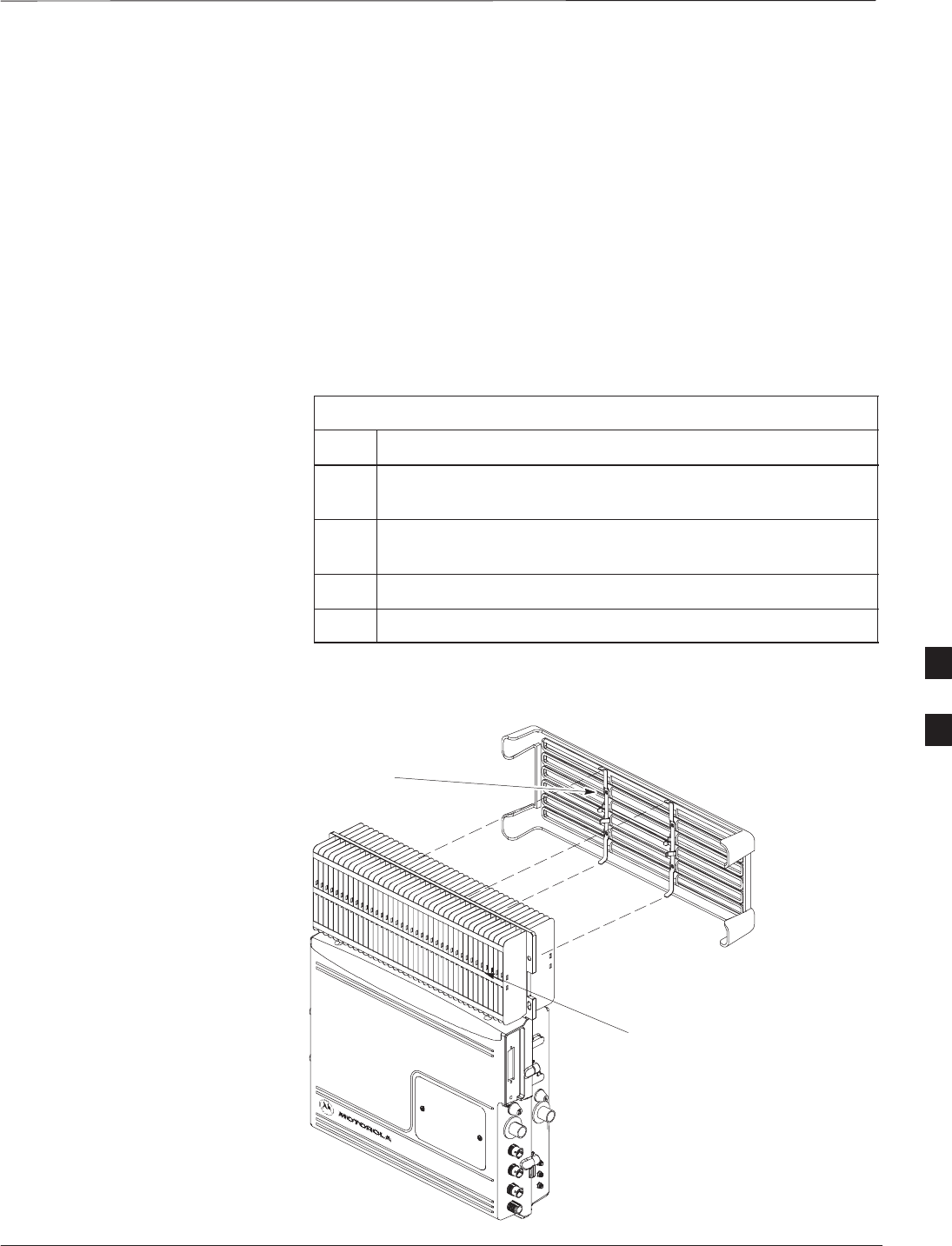
Attach the rear fin cover to the unit by following the procedures in
Table 6-1 and the information in Figure 6-4.
Table 6-1: Procedure to Attach Rear Fin Cover to Units
Step Action
1Install back fin cover prior to placing unit on the mounting
bracket.
2Center fin cover on the fins of the unit. See Figure 6-4 for
snap locations.
3Align snap with center tab on fins.
4Push fin cover into place.
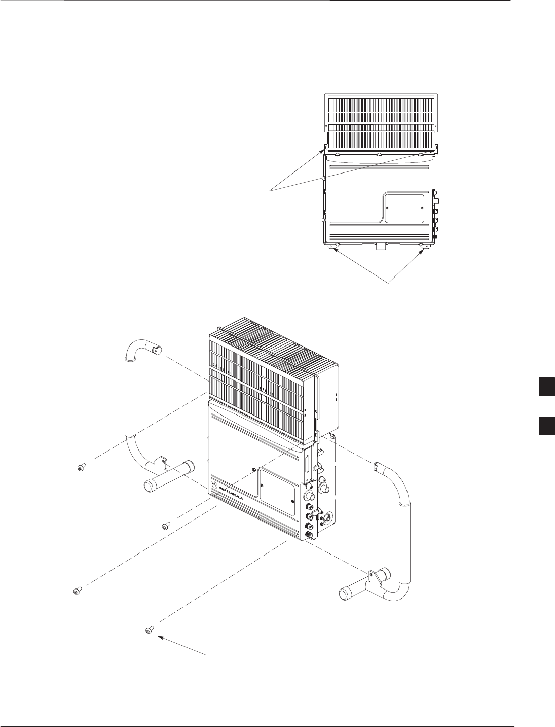
Figure 6-4: Attaching Back Fin Cover to Unit (Picocell Shown)
LOCATION OF SNAPS TO ATTACH
FIN COVER TO UNIT
PICOCELL FINS
6

Attaching Optional Installation Handles to the Unit
PRELIMINARY
SCt300 BTS Hardware Installation, ATP and FRU Procedures DEC 2000
6-6
Objective
The objective of this procedure is to attach the optional installation
handles to the unit. The location for the handles is shown in Figure 6-5.
The handles should be used when lifting or carrying the unit.
Required Tools and Materials
Tools
Attaching the installation handles to the unit requires:
ST30 Torx tamper bit
STorque driver wrench, 1/4–in. hex female drive, 0–10 N–M
Motorola parts
Table 6-2 lists the parts necessary to do this procedure.
Table 6-2: Installation Handle Kit – SGLN5754
Quantity Part Number Description
4 387541C03 Screws M6x190
1 0787668C01 Left Handle
1 0787668C02 Right Handle
Procedure to Attach the
Installation Handles to the Unit
Use the procedure in Table 6-3 to attach the installation handles to the
unit. Refer to Figure 6-5.
Table 6-3: Procedure to Attach the Installation Handles to the Unit
Step Action
1Hold the left handle in position and start the upper screw. The
handles are marked left and right. Refer to Figure 6-5.
2Position and start the lower screw.
3Use a T30 Torx tamper bit to torque both screws to 5.0 N–m.
4Repeat steps 1–3 for the right handle.
6
Attaching Installation Handles to the Unit – continued
DEC 2000 6-7
SCt300 BTS Hardware Installation, ATP and FRU Procedures
PRELIMINARY
Figure 6-5: Attaching the Installation Handles to the Unit (Picocell Shown)
M6X19 (4)
LEFT HANDLE
RIGHT HANDLE
HOLES USED FOR
MOUNTING HANDLES
HOLES USED FOR
MOUNTING HANDLES
0164–O_IL.doc
6
Attaching Unit to Mounting Bracket
PRELIMINARY
SCt300 BTS Hardware Installation, ATP and FRU Procedures DEC 2000
6-8
Objective
The objective of this procedure is to attach the unit to the mounting
bracket. This procedure applies to mounting brackets that are attached to
a rack, wall, ceiling or pole. This procedure also applies to both the
MicroCell and PicoCell units.
Background
The unit attaches to the mounting bracket with two (2) M6 screws and
the provided pin or a customer–supplied padlock.
For ceiling mount applications, two people must do this
procedure. One person must steady the unit while the
second person installs the unit.
WARNING
The handles should be mounted to the unit before
mounting the unit to the bracket. The handles should be
used to lift the unit onto the bracket. If the solar cover is to
be used, the back cover must be attached prior to mounting
the unit. Remove the handles once the unit has been
secured to the mounting bracket.
NOTE
Tools and Materials
The following tools and materials are required to attach the unit to the
mounting bracket:
STorque driver wrench, 1/4–in. hex female drive, 0–10 N–M
ST30 Torx tamper bit
STwo M6X19 screws (Motorola Part Number 0387541C03)
6
Attaching Unit to Mounting Bracket – continued
DEC 2000 6-9
SCt300 BTS Hardware Installation, ATP and FRU Procedures
PRELIMINARY
Procedure to Attach the Unit to
the Mounting Bracket
Follow the procedure in Table 6-4 to attach the unit to the mounting
bracket. Refer to Figure 6-6.
For ceiling mount applications, two people must do this
procedure. One person must steady the unit while the
second person installs the unit.
WARNING
Use caution when resting the MicroCell or PicoCell unit
on the hooks of the mounting bracket. Do not leave unit
supported by hooks only.
CAUTION
Table 6-4: Procedure to Attach the Unit to the Mounting Bracket
Step Action
1Lift the unit using the installation handles and place it on the
mounting bracket by aligning the bracket’s upper arms into
the rectangular cutouts in the heatsink. The unit will need to
be raised up slightly so that the lower bracket flange does not
contact the unit’s lower surface. For a ceiling application, use
caution when resting the PicoCell on the hooks on the
mounting bracket.
2Use a T30 Torx tamper bit to start, but not tighten, both
screws in the location shown in Figure 6-6.
3At the bottom of the unit, align the hole in the mounting
bracket with the hole in the unit. Place the pin or
customer–supplied padlock through this hole. Screw pin
together and tighten firmly.
4Use a T30 Torx tamper bit to torque the two mounting screws
to 5.0 N–M.
5Use a T30 Torx tamper bit to remove the installation handles.
6
Attaching Unit to Mounting Bracket – continued
PRELIMINARY
SCt300 BTS Hardware Installation, ATP and FRU Procedures DEC 2000
6-10
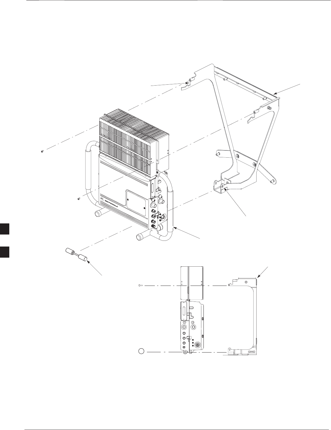
Figure 6-6: Attaching the Unit to the Mounting Bracket
ATTACH THE HANDLES TO THE UNIT
BEFORE LIFTING
HOOKS
MOUNTING BRACKET
SLIDE PIN THROUGH HOLES IN
BRACKET AND SCREW TOGETHER
MOUNTING BRACKET
M6 SCREWS (2)
PIN (P/N 5587660C03)
6

Earth Ground Cabling
DEC 2000 6-11
SCt300 BTS Hardware Installation, ATP and FRU Procedures
PRELIMINARY
Objective
The objective of this procedure is to attach the earth ground cabling to
one or more MicroCell or PicoCell units. This procedure covers just the
grounding cables that attach to the MicroCell or PicoCell.
Other Grounding
Considerations
Grounding considerations beyond the ground cables that attach to the
MicroCell and PicoCell are summarized in Appendix A. Refer to
Appendix A and the site documentation for other grounding
considerations.
If your site is equipped with the optional Primary Surge Suppressor,
refer to the “Power, Earth Ground, and Battery Cabling” Procedure in
chapter 4 for information about installing the Master Ground cable.
Cable Description
The following cables in Table 6-5 are necessary to do this procedure.
Table 6-5: Ground Cable Description and Part Number
Cable Qty. Part Number Description
A 1–4 3087701C02 Ground cable, 8 -AWG, insulated copper wire. Requires one ring lug
connector. Used for Primary Surge Suppressor Installation.
B 1–4 3087701C01 Ground cable, Site I/O Junction Box to Bracket.
Y 1 Customer
Supplied Master Ground Cable, 6 -AWG, insulated copper wire. Used for both
Primary Surge Suppressor and non–Primary Surge Suppressor
installations.
Tools and Materials
The following tools are required to attach ground cabling to the
MicroCell and PicoCell units.
S13 mm torque wrench set to 5.0 N–M
SFlathead screwdriver bit
ST30 TORX bit
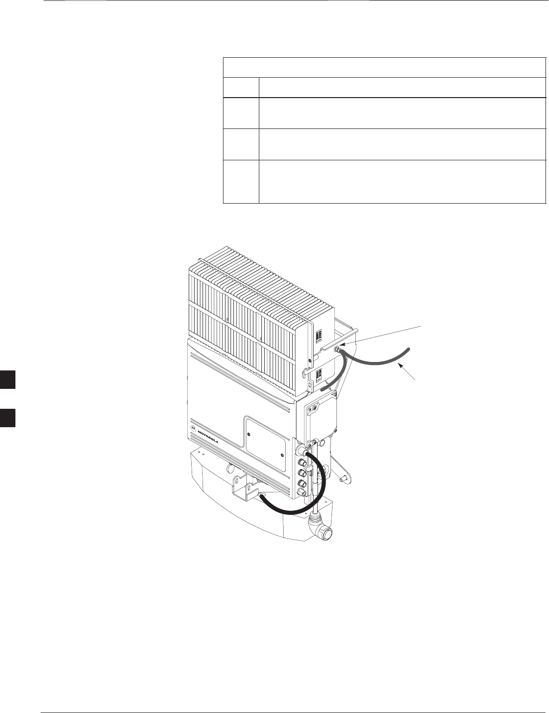
Procedure
Use the following procedure to attach the ground cables. Refer to
Table 6-6 and Figure 6-7.
Table 6-6: Procedure to Attach the Earth Ground Cables
Step Action
1Remove the hex nuts and lock washers from the ground stud
on the mounting bracket.
2Attach ground cable (cable A or Y) to ground stud on
mounting bracket.
. . . continued on next page
6
Earth Ground Cabling – continued
PRELIMINARY
SCt300 BTS Hardware Installation, ATP and FRU Procedures DEC 2000
6-12
Table 6-6: Procedure to Attach the Earth Ground Cables
Step Action
3Replace one lock washer and nut on the ground stud and
tighten to 5 N–m.
4Attach the ground cable from the Site I/O junction box (cable
B) to the ground stud on the mounting bracket.
5Replace the second lockwasher and hex nut to the ground stud
on mounting bracket. Use a torque wrench and a 13mm
socket to tighten to 5.0 N–m.
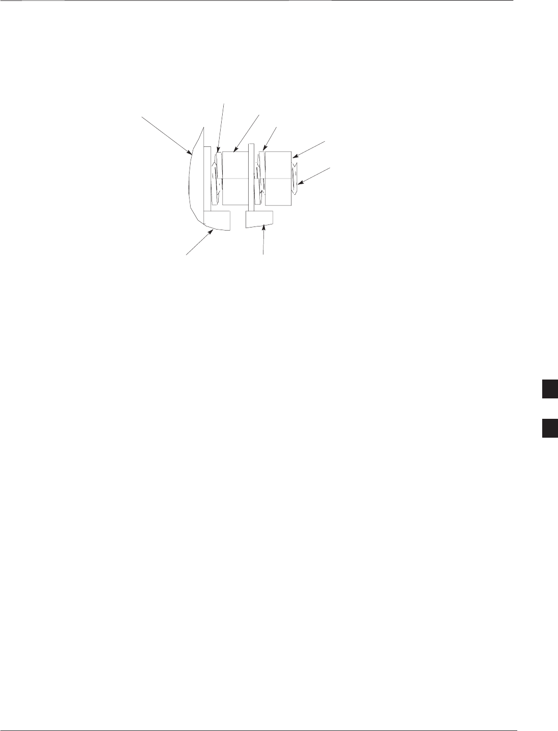
Figure 6-7: Detail Location of Ground Stud
GROUNDING STUD
TO CUSTOMER DEFINED MASTER
GROUND PLATE OR CARRIER
GROUND CONNECTOR ON PRIMARY
SURGE SUPPRESSOR
CABLE A OR Y
B
6
Earth Ground Cabling – continued
DEC 2000 6-13
SCt300 BTS Hardware Installation, ATP and FRU Procedures
PRELIMINARY
Figure 6-8: Grounding Stud on Mounting Bracket
LOCK WASHER
NUT
NUT
LOCK WASHER
MOUNTING BRACKET
CUSTOMER UNIT
GROUND LUG
SITE I/O
GROUND LUG
GROUNDING STUD
6
Attaching Front Fin Cover to Unit
PRELIMINARY
SCt300 BTS Hardware Installation, ATP and FRU Procedures DEC 2000
6-14
Objective
The objective of this procedure is to attach the front fin cover to the
PicoCell and MicroCell units.
When to Use the Fin Covers
Always use fin covers for an indoor application.
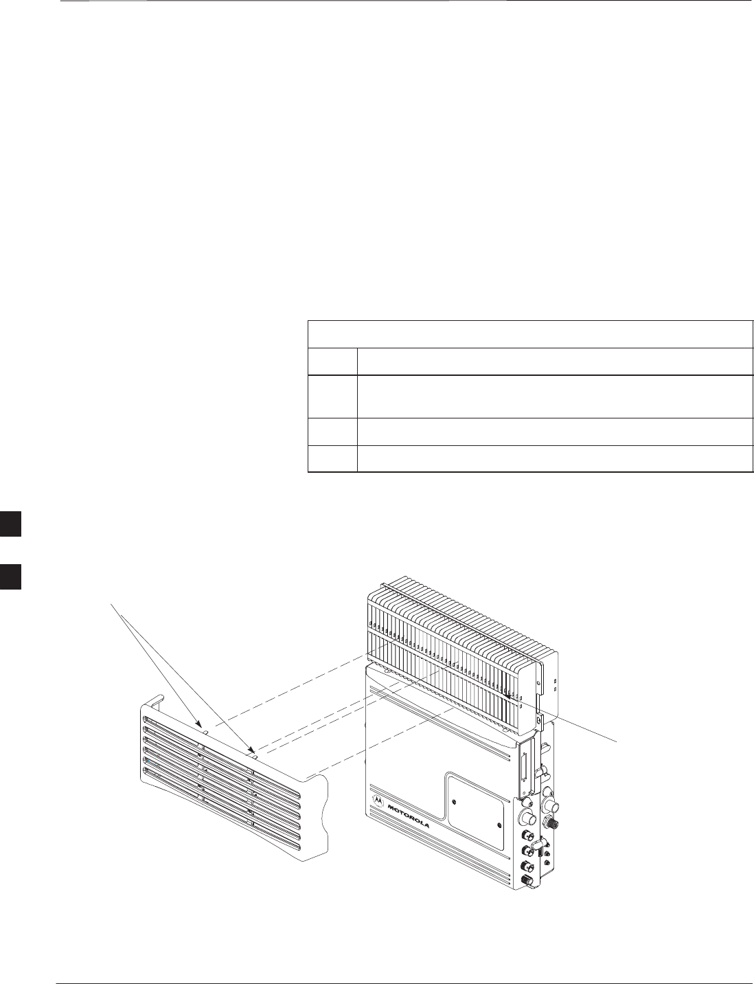
Procedure
Follow the procedure in Table 6-7 to attach the front fin cover to the
unit. Refer to Figure 6-9.
Table 6-7: Procedure to Attach Front Fin Cover to Unit
Step Action
1Center fin cover on the fins of the unit. See Figure 6-9 for
snap locations.
2Align snap with center tab on fins.
3Push fin cover into place.
Figure 6-9: Attaching Front Fin Cover to Unit (Picocell Shown)
PICOCELL FINS
LOCATION OF SNAPS TO ATTACH
FIN COVER TO UNIT
6

Attaching the Site I/O Junction Box to the Unit
DEC 2000 6-15
SCt300 BTS Hardware Installation, ATP and FRU Procedures
PRELIMINARY
Objective
The objective of this procedure is to attach the Site I/O junction box to
the unit. The location for the Site I/O junction box is shown in
Figure 6-10.
If you do not mount a Site I/O Junction box to a unit, leave the installed
Site I/O caps on the Site I/O Junction box connectors.
Required Tools and Materials
The following tools and materials are necessary to do this procedure:
STorque driver wrench, 1/4–in. hex female drive, 0–10 N–M
ST30 Torx tamper bit
SSite I/O Junction box
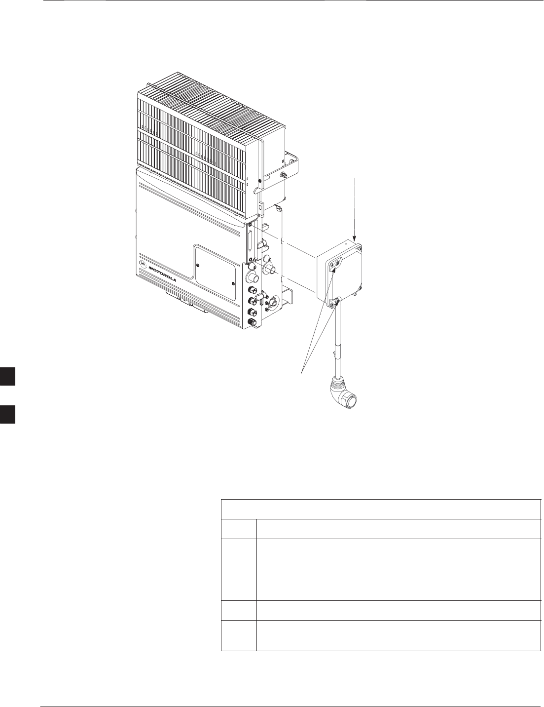
Procedure to Attach the Site
I/O Junction Box to the Unit
Follow the procedure below to attach the site I/O junction box to the
unit.
Table 6-8: Procedure to Attach the Site I/O Junction Box to the Unit
Step Action
1Use a T30 TORX bit to remove Site I/O Cap from the Site
I/O connector.
NOTE
Save Site I/O Cap for future use.
2Remove the Site I/O Plate from the Site I/O Junction Box.
3Attach one end of the Site I/O Ground cable to the Site I/O
Junction Box. Use one M6x19 tamper–resistant screw.
Torque to 5.0 N–m.
4The free end of the Site I/O junction box cable should be
connected to the customer–supplied Site I/O interface or to
the Primary Surge Suppressor.
5Position the Site I/O junction box as shown in NO TAG.
6Insert the Site I/O junction box on to the housing, using the
alignment feature on the housing.
7Use a T30 Torx tamper bit to tighten (but do not torque) the
upper tamper resistant screw.
8Tighten but do not torque the lower tamper resistant screw.
9Use a T30 Torx tamper bit to torque the upper and lower
screw to 5 N–m.
6
Attaching the Site I/O Junction Box to the Unit – continued
PRELIMINARY
SCt300 BTS Hardware Installation, ATP and FRU Procedures DEC 2000
6-16
Figure 6-10: Attaching the Site I/O Junction Box to the Unit
SITE I/O JUNCTION BOX
CAPTIVE SCREWS
Procedure to Attach a Site I/O
Cap to the Unit (optional)
Use the following procedure in Table 6-9 to attach a Site I/O Cap to the
unit.
Table 6-9: Procedure to Attach a Site I/O Cap to the Unit (optional)
Step Action
1Position the Site I/O cap, Motorola Part Number
3888121C01, over the Site I/O socket.
2Use a T30 Torx tamper bit to tighten (but do not torque) the
upper tamper resistant screw.
3Tighten but do not torque the lower tamper resistant screw.
4Use a T30 Torx tamper bit to torque the upper and lower
screw to 5 N–m.
6

Attaching the Short Duration Battery to the Unit (optional)
DEC 2000 6-17
SCt300 BTS Hardware Installation, ATP and FRU Procedures
PRELIMINARY
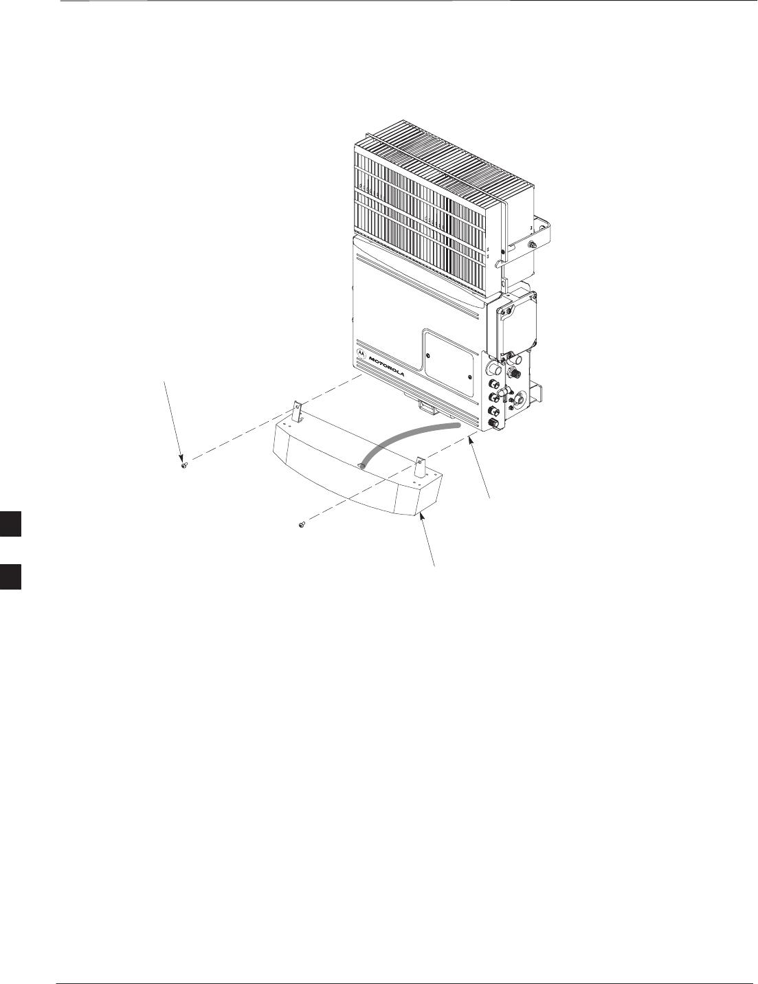
Objective
The objective of this procedure is to attach the short duration battery to
the unit.
Required Tools and Materials
Attaching the battery to the unit requires:
ST30 Torx tamper bit, 1/4–in. hex
STorque driver wrench, 1/4–in. hex female drive, 0–10 N–M
STwo (2) Screws M6x19 (Motorola Part Number 0387541C03)
Procedure to Attach the
Battery to the Unit
Follow the procedure in Table 6-10 to attach the short duration battery to
the unit. Refer to Figure 6-11.
Table 6-10: Procedure to Attach the Short Duration Battery to the Unit
Step Action
1Hold the battery in the position shown in Figure 6-11.
2The two holes at the end of the battery should align with the
mounting holes on the unit. See Figure 6-11.
3Start but do not tighten the M6x19 screws.
4Using a T30 Torx tamper bit wrench, 1/4–in. hex female
drive, 0–10 N–M, torque the screws to 5 N–M.
6
Attaching the Short Duration Battery to the Unit (optional) – continued
PRELIMINARY
SCt300 BTS Hardware Installation, ATP and FRU Procedures DEC 2000
6-18
Figure 6-11: Attaching the Short Duration Battery to the Unit
M6X19 SCREWS (2)
CONNECT TO DC INPUT CONNECTOR
WHEN BATTERY HAS BEEN SECURED
SHORT DURATION
BATTERY
6

Short Duration Battery Cabling
DEC 2000 6-19
SCt300 BTS Hardware Installation, ATP and FRU Procedures
PRELIMINARY
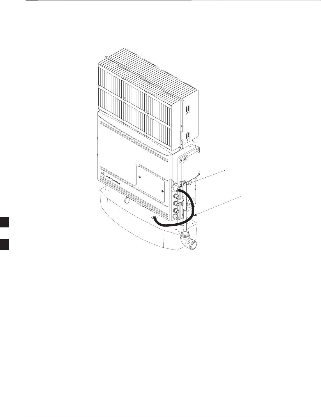
Objective
The objective of this procedure is to attach the short duration battery
cable.
Battery Cable
The battery cable is part of the battery assembly. The same type
connector is used for the short duration battery and DC input cables.
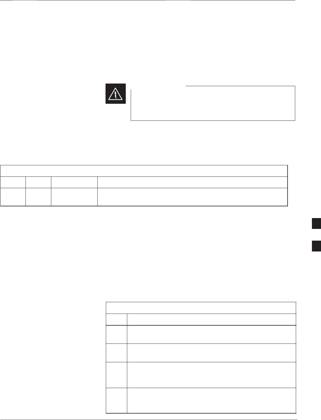
Procedure
Use the following procedure in Table 6-11 to attach the short duration
battery (DC input) cable to the DC input connector. Refer to
Figure 6-12. The cable should be connected before the solar cover is
attached.
The short duration battery should not be opened under any
circumstances. No wire termination is required by the user except
connection to the BTS, with the provided connector.
Table 6-11: Procedure to Connect the Short Duration Battery Cable to
Unit
Step Action
1Ensure that the ground wire has a connection to unit and the
Master Ground Bus (also called Master Ground Plate).
2Verify that the DC power breaker is open. The white collar on
the breaker is visible when it is open.
3Place the round, black connector of the DC input cable onto
the DC input connector on the BTS. Refer to Figure 6-12.
Turn the cable connector to align its key.
4Hand tighten the connector (a clicking sound is heard, this is
normal). When the red line on the connector on the unit is
covered, connection is complete.
6
Short Duration Battery Cabling – continued
PRELIMINARY
SCt300 BTS Hardware Installation, ATP and FRU Procedures DEC 2000
6-20
Figure 6-12: Battery Cable Installation
DC INPUT CONNECTOR
BATTERY CABLE IS PART
OF BATTERY ASSEMBLY
6
AC Power Cabling
DEC 2000 6-21
SCt300 BTS Hardware Installation, ATP and FRU Procedures
PRELIMINARY
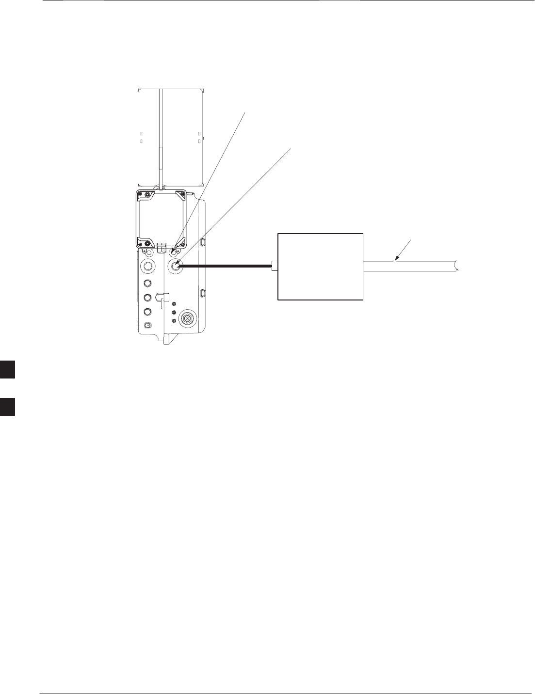
Objective
The objective of this procedure is to attach the AC input power cable to
the unit. Use this procedure only when AC power is used to power the
unit.
If the Primary Surge Suppressor is not used, the AC Installation Box is
required for all outdoor mounting applications.
This equipment uses dangerous voltages and is capable of
causing death. Use extreme caution when handling and
testing this equipment.
WARNING
Cable Description
The following cables in Table 6-5 are necesary to do this procedure:
Table 6-12: AC Input Cable Description and Part Number
Cable Qty. Part Number Description
S 1–4 3087854C02 AC input cable, 18 AWG, 5 m, is designed for 120–240 VAC power
input. Cable has Deutsch connector on both ends.
Power Cable and Connector
Signal Information
The AC input connector is located on the side of the unit as shown in
Figure 6-13. The unit is designed for 88–260 VAC power input.
Procedure
Use the following procedure in Table 6-13 to connect the AC input cable
to the unit. The AC input cable should be connected before the solar
cover is attached.
Table 6-13: Procedure to Connect AC Power to the Unit
Step Action
1Ensure that the ground wire has a connection to the Master
Ground Bus (also called Master Ground Plate).
2Verify that the AC power breaker is open. The white collar on
the breaker is visible when it is open.
3Place the round, black connector on the AC input cable (cable
S) onto the AC input connector. See Figure 6-13. Turn the
cable connector to align its key.
4Hand tighten the connector (a clicking sound is heard, this is
normal). When the red line on the connector on the unit is
covered, connection is complete.
6
AC Power Cabling – continued
PRELIMINARY
SCt300 BTS Hardware Installation, ATP and FRU Procedures DEC 2000
6-22
Figure 6-13: AC Power Cabling Details
AC INSTALL BOX
OR AC POWER
SOURCE OR
OPTIONAL
PRIMARY SURGE
SUPPRESSOR
AC INPUT
CONNECTOR
AC POWER
BREAKER
S
AC CONDUIT
6
DC Power Cabling
DEC 2000 6-23
SCt300 BTS Hardware Installation, ATP and FRU Procedures
PRELIMINARY
Objective
The objective of this procedure is to attach the DC input cable to the
unit. Use this procedure only when DC power is used to power the unit.
This equipment uses dangerous voltages and is capable of
causing death. Use extreme caution when handling and
testing this equipment.
WARNING
Cable Decription
The following cables in Table 6-14 are necessary to do this procedure.
Table 6-14: DC Input Cable Description and Part Number
Cable Qty. Part Number Description
U 1 3087854C04 DC input cable, 18 AWG, 5 m, is designed for 20 to 30 VDC power
input.
Power Cable and Connector
Signal Information
The DC input connector is located on the side of the unit. The unit is
designed for 40 to 60 VDC.
Procedure
Use the following procedure in Table 6-15 to connect the DC input cable
to the unit. Refer to Figure 6-14. The DC input cable should be
connected before the solar cover is attached.
Table 6-15: Procedure to Connect DC Power to the Unit
Step Action
1Ensure that the ground wire has a connection to the Master
Ground Bus (also called Master Ground Plate).
2Verify that the DC power breaker is open. The white collar on
the breaker is visible when it is open.
3Place the round, black connector of the DC input cable onto
the DC input connector. See Figure 6-14. Turn the cable
connector to align its key.
4Hand tighten the connector (a clicking sound is heard, this is
normal). When the red line on the connector on the unit is
covered, connection is complete.
6
DC Power Cabling – continued
PRELIMINARY
SCt300 BTS Hardware Installation, ATP and FRU Procedures DEC 2000
6-24
Figure 6-14: DC Power Cabling Details
DC INPUT
CONNECTOR
DC POWER
SOURCE
DC POWER BREAKER
U
0178–O_IL.doc
6

Antenna Cabling for Sites Equipped With Customer–Supplied Site I/O
Interface
DEC 2000 6-25
SCt300 BTS Hardware Installation, ATP and FRU Procedures
PRELIMINARY
Objective
The objective of this procedure is to attach the antenna cabling for one or
more units.
If your BTS is equipped with the optional Primary Surge Suppressor,
then proceed to the “Antenna Cabling for Sites Equipped with the
Optional Primary Surge Suppressor” procedure in Chapter 6.
Cable Labels
The cable designations are referenced to Table 6-16 in the “Cable
Description” area of Chapter 4.
Cable Descriptions
The following cables in Table 6-16 are necessary to do this procedure.
Table 6-16: Cable Descriptions and Part Numbers
Cable Qty. Part Number Description
C 1–8 Customer
Supplied Antenna cable, 50–Ohm coaxial terminated with at least one male,
N–type connector.
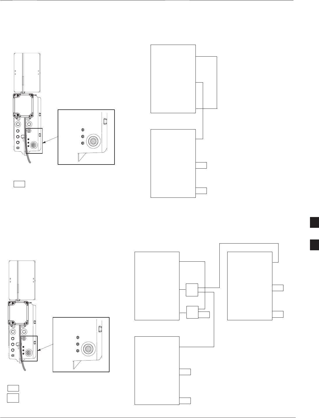
Procedure
The cabling is installed between the unit(s) and the external lightning
arrestors. If lightning arrestors are not present, it connects to the
antenna.
If your BTS has one unit, cable the unit as shown in Figure 6-15.
Torque the connectors to 4.3 N–M.
If your BTS has more than one unit, cable the unit as shown in
Figure 6-18, Figure 6-17, Figure 6-16, Figure 6-21, Figure 6-20, or
Figure 6-19.
6
Antenna Cabling for Sites Equipped With Customer–Supplied Site I/O
Interface – continued
PRELIMINARY
SCt300 BTS Hardware Installation, ATP and FRU Procedures DEC 2000
6-26
Figure 6-15: Antenna Cabling Details for MicroCell and PicoCell Unit
LIGHTNING
ARRESTOR
TX/RX
ANTENNA
LIGHTNING
ARRESTOR
RX
ANTENNA
LIGHTNING
ARRESTOR
TX/RX
ANTENNA
MICROCELL UNIT
PICOCELL UNIT
C
ANTENNA A ANTENNA B
ANTENNA A
C
C
C
C
C
6
Antenna Cabling for Sites Equipped With Customer–Supplied Site I/O
Interface – continued
DEC 2000 6-27
SCt300 BTS Hardware Installation, ATP and FRU Procedures
PRELIMINARY
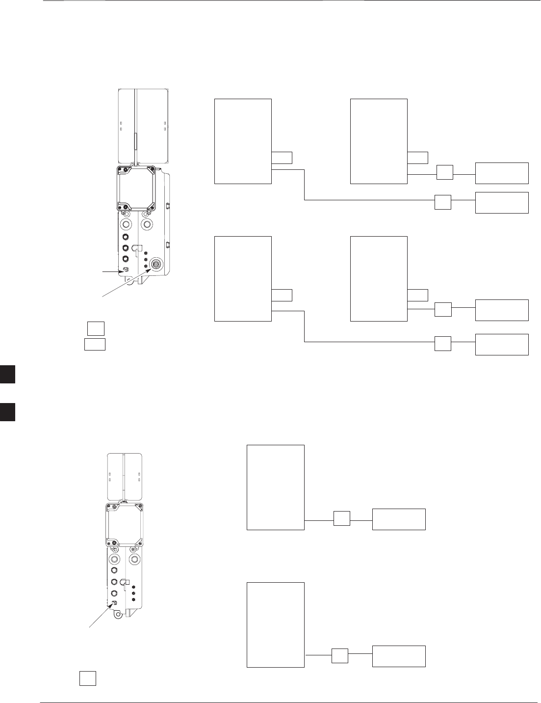
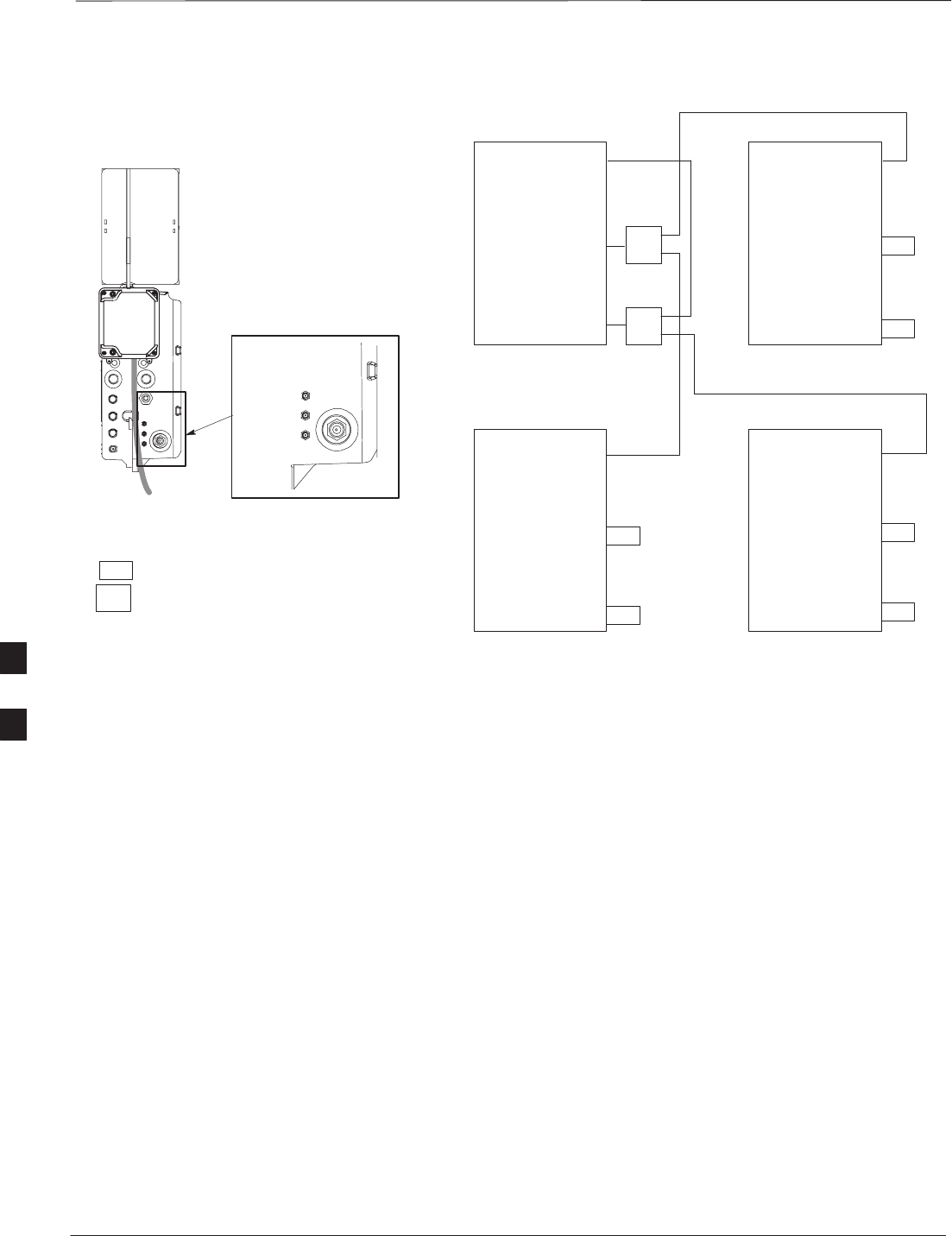
Figure 6-16: Antenna Cabling for Two Microcells
MICROCELL UNIT
ANTENNA A
ANT A
ANT B
RFT
ANT A
ANT B
RFT
LA
MICROCELL 1
MICROCELL 2
LA ANTENNA 2
TX/RX
LA ANTENNA 1
TX/RX
RFT
= LIGHTNING ARRESTOR
= 50 OHM RF TERMINATOR
KEY
C
C
ANTENNA B
Figure 6-17: Antenna Cabling for Three Microcells
MICROCELL UNIT
ANTENNA A
ANT A
ANT B
ANT A
ANT B
RFT
ANT A
ANT B
RFT
LA
LA
MICROCELL 1MICROCELL 3
MICROCELL 2
ANTENNA 3
TX/RX
LA ANTENNA 4
RX
LA ANTENNA 2
TX/RX
LA ANTENNA 1
TX/RX
RFT
= LIGHTNING ARRESTOR
= 50 OHM RF TERMINATOR
KEY
C
C
C
C
ANTENNA B
6
Antenna Cabling for Sites Equipped With Customer–Supplied Site I/O
Interface – continued
PRELIMINARY
SCt300 BTS Hardware Installation, ATP and FRU Procedures DEC 2000
6-28
Figure 6-18: Antenna Cabling for Four Microcells
MICROCELL UNIT
ANTENNA A
ANTENNA B
ANT A
ANT B
RFT ANT A
ANT B
RFT
ANT A
ANT B
RFT ANT A
ANT B
RFT
LA
LA
MICROCELL 1MICROCELL 3
MICROCELL 2MICROCELL 4
ANTENNA 3
TX/RX
LA ANTENNA 4
TX/RX
LA ANTENNA 2
TX/RX
LA ANTENNA 1
TX/RX
RFT
= LIGHTNING ARRESTOR
= 50 OHM RF TERMINATOR
KEY
C
C
C
C
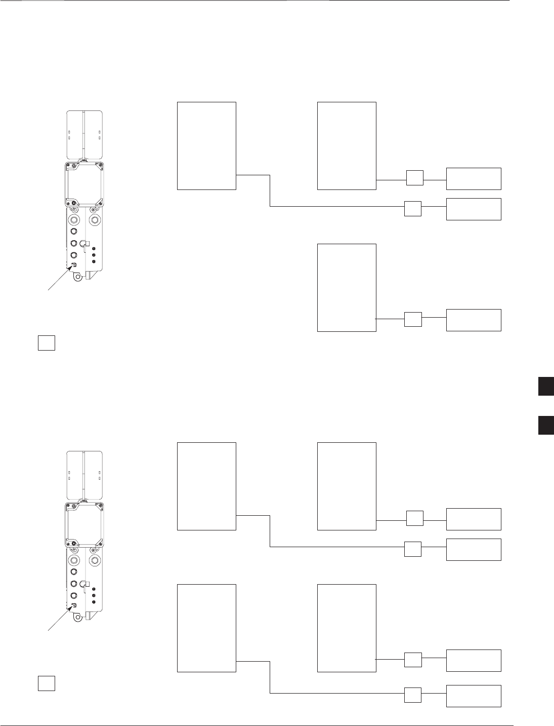
Figure 6-19: Antenna Cabling for Two Picocells
ANT A
ANT A
LA
PICOCELL 1
PICOCELL 2
LA ANTENNA 2
TX/RX
LA ANTENNA 1
TX/RX
= LIGHTNING ARRESTOR
KEY
PICOCELL UNIT
ANTENNA A
C
C
6
Antenna Cabling for Sites Equipped With Customer–Supplied Site I/O
Interface – continued
DEC 2000 6-29
SCt300 BTS Hardware Installation, ATP and FRU Procedures
PRELIMINARY
Figure 6-20: Antenna Cabling for Three Picocells
ANT A ANT A
ANT A
LA
LA
PICOCELL 1PICOCELL 3
PICOCELL 2
ANTENNA 3
TX/RX
LA ANTENNA 2
TX/RX
LA ANTENNA 1
TX/RX
= LIGHTNING ARRESTOR
KEY
PICOCELL UNIT
ANTENNA A
C
C
C
Figure 6-21: Antenna Cabling for Four Picocells
ANT A ANT A
ANT A ANT A
LA
LA
PICOCELL 1PICOCELL 3
PICOCELL 2PICOCELL 4
ANTENNA 3
TX/RX
LA ANTENNA 4
TX/RX
LA ANTENNA 2
TX/RX
LA ANTENNA 1
TX/RX
= LIGHTNING ARRESTOR
KEY
PICOCELL UNIT
ANTENNA A
C
C
C
C
6

Antenna Cabling for Sites Equipped with Optional Primary Surge
Suppressor
PRELIMINARY
SCt300 BTS Hardware Installation, ATP and FRU Procedures DEC 2000
6-30
Objective
The objective of this procedure is to attach the antenna cabling for one or
more units at a site equipped with the optional Primary Surge
Suppressor.
Cable Labels
The cable designations are referenced to Table 6-17 in the “Cable
Description” area of Chapter 4.
Cable Descriptions
The following cables in Table 6-17 are necessary to do this procedure.
Table 6-17: Cable Descriptions and Part Numbers
Cable Qty. Part Number Description
C 1–8 Customer
Supplied Antenna cable, 50–Ohm coaxial terminated with at least one male,
N–type connector.
D 2–6 Customer
Supplied Antenna cable, terminated with 2 male N–type connectors
Procedure
Lightning arrestors are shipped/installed in the Primary Surge
Suppressor for one or two unit configurations. If you are expanding
from two to three or from three to four units, then you must install
lightning arrestors for units three and four. Refer to the procedure in
Table 6-18 to install antenna lightning arrestors.
If your BTS has one unit and is equipped with the Primary Surge
Suppressor, cable the unit as shown in Figure 6-23.
If your BTS has more than one unit and is equipped with the Primary
Surge Suppressor, cable the units as shown in Figure 6-24 through
Figure 6-29.
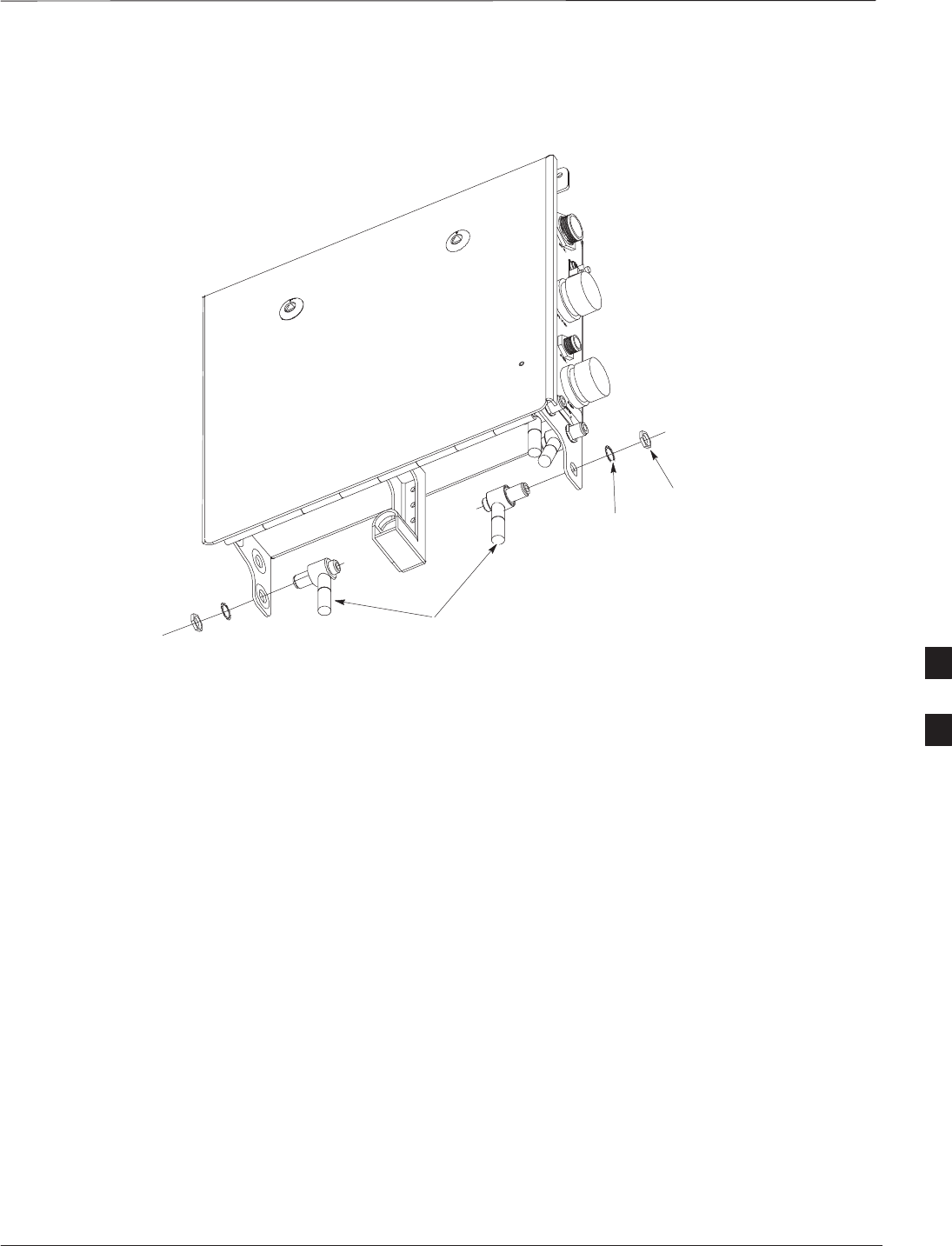
Table 6-18: Procedure to Install Antenna Lightning Arrestors
Step Action
1Remove the 3/4–in. nut and lock washer from N–type
connector on antenna lightning arrestor. Refer to Figure 6-22.
2Insert the antenna lightning arrestor through hole in mounting
flange.
NOTE
NOTE
Antenna cable connectors may be connected to either side of
the antenna protectors on the Primary Surge Suppressor.
3Install the lockwasher and 3/4–in. nut on the N–type
connector.
4Use a 3/4–in. wrench to tighten to 20 N–m.
6
Antenna Cabling for Sites Equipped with Optional Primary Surge
Suppressor – continued
DEC 2000 6-31
SCt300 BTS Hardware Installation, ATP and FRU Procedures
PRELIMINARY
Figure 6-22: Installation of Third and Fourth Antenna Lightning Arrestors
ANTENNA LIGHTNING
ARRESTORS
LOCKWASHER
3/4–IN NUT
6
Antenna Cabling for Sites Equipped with Optional Primary Surge
Suppressor – continued
PRELIMINARY
SCt300 BTS Hardware Installation, ATP and FRU Procedures DEC 2000
6-32
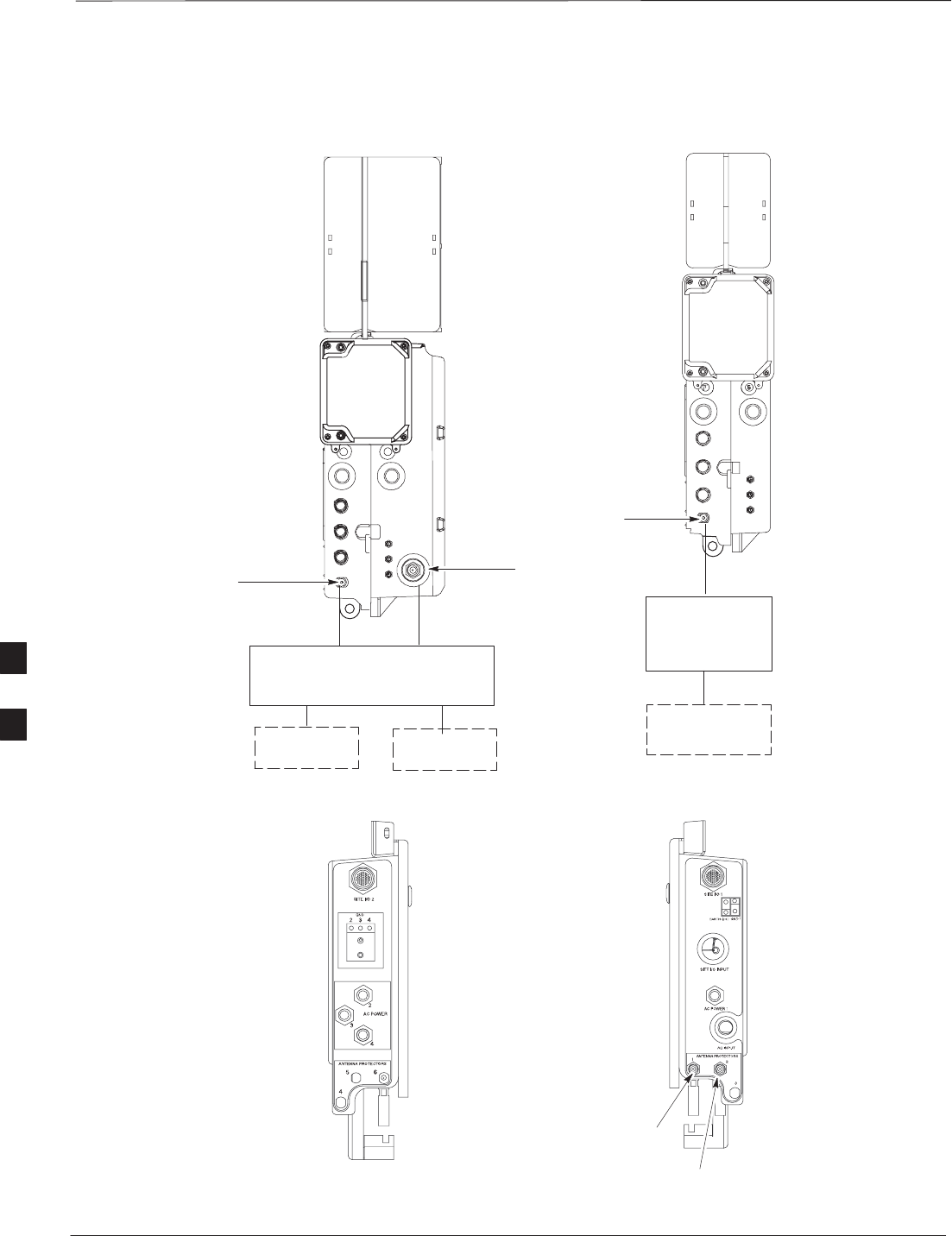
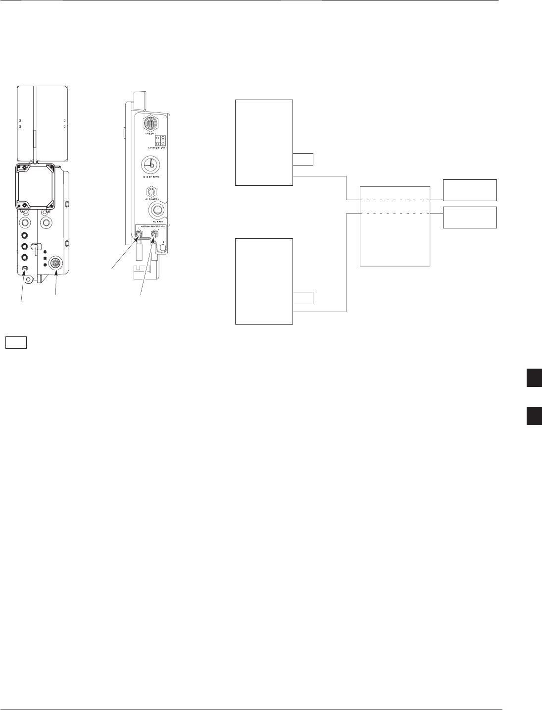
Figure 6-23: Antenna Cabling Details for MicroCell and PicoCell Unit Equipped with Primary Surge
Suppressor
TX/RX
ANTENNA
RX
ANTENNA
TX/RX
ANTENNA
MICROCELL UNIT PICOCELL UNIT
ANTENNA A ANTENNA B
ANTENNA A
PRIMARY
SURGE
SUPPRESSOR
PRIMARY
SURGE
SUPPRESSOR
12
1
ANTENNA LIGHTNING
ARRESTOR 1
ANTENNA LIGHTNING
ARRESTOR 2
PRIMARY SURGE
SUPPRESSOR
(RIGHT SIDE)
PRIMARY SURGE
SUPPRESSOR
(LEFT SIDE)
DD
D
C
CC
6
Antenna Cabling for Sites Equipped with Optional Primary Surge
Suppressor – continued
DEC 2000 6-33
SCt300 BTS Hardware Installation, ATP and FRU Procedures
PRELIMINARY
Figure 6-24: Antenna Cabling for Two Microcells Equipped with Primary Surge Suppressor
MICROCELL UNIT
ANTENNA A
ANT A
ANT B
RFT
ANT A
ANT B
RFT
MICROCELL 1
MICROCELL 2
RFT = 50 OHM RF TERMINATOR
KEY
D
D
ANTENNA B
PRIMARY
SURGE
SUPPRESSOR
ANTENNA 1
TX/RX
ANTENNA 2
TX/RX
ANTENNA
PROTECTOR 1
ANTENNA
PROTECTOR 2
PRIMARY SURGE
SUPPRESSOR
(RIGHT SIDE)
1
2
C
C
6
Antenna Cabling for Sites Equipped with Optional Primary Surge
Suppressor – continued
PRELIMINARY
SCt300 BTS Hardware Installation, ATP and FRU Procedures DEC 2000
6-34
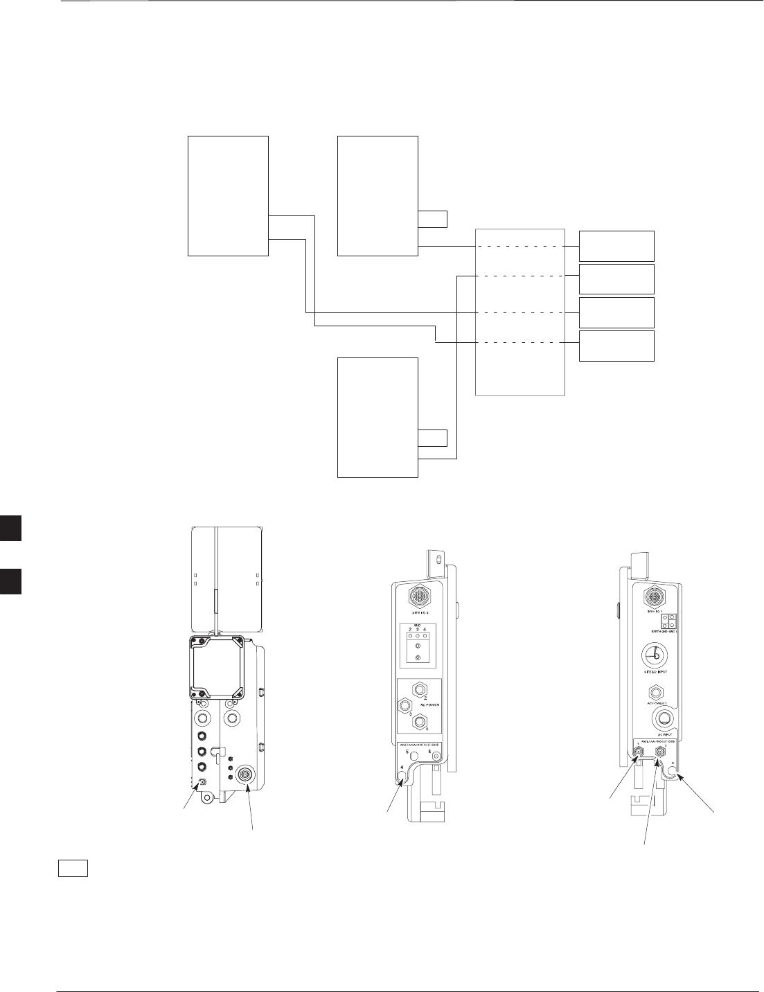
Figure 6-25: Antenna Cabling for Three Microcells Equipped with Primary Surge Suppressor
MICROCELL UNIT
ANTENNA A
ANT A
ANT B
ANT A
ANT B
RFT
ANT A
ANT B
RFT
MICROCELL 1MICROCELL 3
MICROCELL 2
ANTENNA 3
TX/RX
ANTENNA 4
RX
ANTENNA 2
TX/RX
ANTENNA 1
TX/RX
RFT = 50 OHM RF TERMINATOR
KEY
D
DD
D
ANTENNA B
PRIMARY
SURGE
SUPPRESSOR
ANTENNA
PROTECTOR 1
ANTENNA
PROTECTOR 2
ANTENNA
PROTECTOR 3
(SEE NOTE)
PRIMARY SURGE
SUPPRESSOR
(RIGHT SIDE)
1
2
3
4
PRIMARY SURGE
SUPPRESSOR
(LEFT SIDE)
ANTENNA
PROTECTOR 4
(SEE NOTE)
C
C
C
C
NOTE: YOU MUST INSTALL
ANTENNA PROTECTOR
6
Antenna Cabling for Sites Equipped with Optional Primary Surge
Suppressor – continued
DEC 2000 6-35
SCt300 BTS Hardware Installation, ATP and FRU Procedures
PRELIMINARY
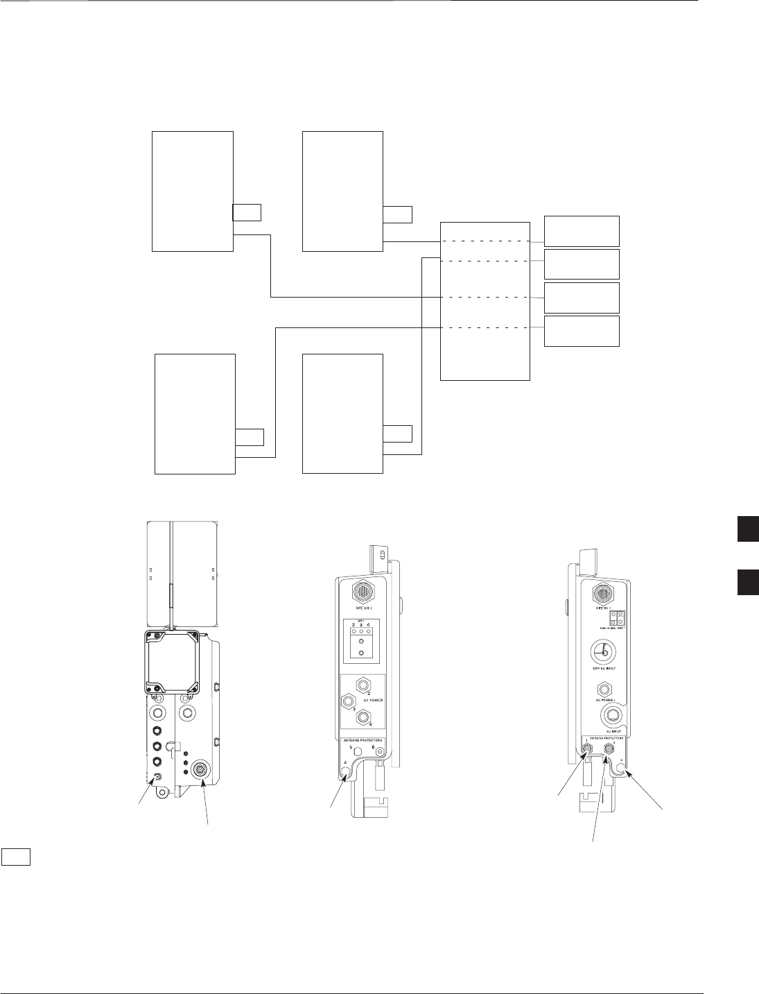
Figure 6-26: Antenna Cabling for Four Microcells Equipped with Primary Surge Suppressor
ANT A
ANT B
ANT A
ANT B
RFT
ANT A
ANT B
RFT
MICROCELL 1MICROCELL 3
MICROCELL 2
ANTENNA 3
TX/RX
ANTENNA 4
TX/RX
ANTENNA 2
TX/RX
ANTENNA 1
TX/RX
RFT = 50 OHM RF TERMINATOR
KEY
DD
D
PRIMARY
SURGE
SUPPRESSOR
ANT A
ANT B
MICROCELL 4
RFT
RFT
D
ANTENNA
PROTECTOR 1
ANTENNA
PROTECTOR 2
ANTENNA
PROTECTOR 3
(SEE NOTE)
PRIMARY SURGE
SUPPRESSOR
(RIGHT SIDE)
MICROCELL UNIT
ANTENNA A
ANTENNA B
PRIMARY SURGE
SUPPRESSOR
(LEFT SIDE)
ANTENNA
PROTECTOR 4
(SEE NOTE)
1
2
3
4
C
C
C
C
NOTE: YOU MUST INSTALL
ANTENNA PROTECTOR
6
Antenna Cabling for Sites Equipped with Optional Primary Surge
Suppressor – continued
PRELIMINARY
SCt300 BTS Hardware Installation, ATP and FRU Procedures DEC 2000
6-36
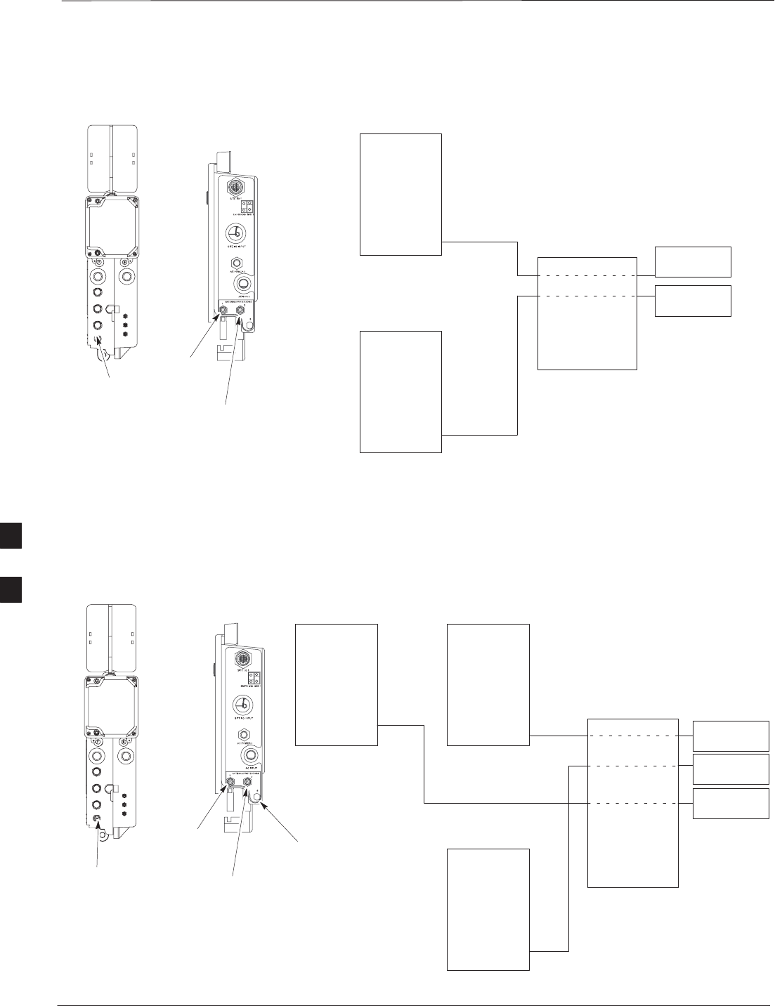
Figure 6-27: Antenna Cabling for Two Picocells Equipped with Primary Surge Suppressor
PICOCELL UNIT
ANTENNA A
ANT A
ANT A
PICOCELL 1
PICOCELL 2
D
D
PRIMARY
SURGE
SUPPRESSOR
ANTENNA 1
TX/RX
ANTENNA 2
TX/RX
ANTENNA
PROTECTOR 1
ANTENNA
PROTECTOR 2
PRIMARY SURGE
SUPPRESSOR
(RIGHT SIDE)
1
2
C
C
Figure 6-28: Antenna Cabling for Three Picocells Equipped with Primary Surge Suppressor
PICOCELL UNIT
ANTENNA A
ANT A ANT A
ANT A
PICOCELL 1PICOCELL 3
PICOCELL 2
ANTENNA 3
TX/RX
ANTENNA 2
TX/RX
ANTENNA 1
TX/RX
DD
D
PRIMARY
SURGE
SUPPRESSOR
ANTENNA
PROTECTOR 1
ANTENNA
PROTECTOR 2
ANTENNA
PROTECTOR 3
(SEE NOTE)
PRIMARY SURGE
SUPPRESSOR
(RIGHT SIDE)
1
2
3
C
C
C
NOTE: YOU MUST INSTALL
ANTENNA PROTECTOR
6
Antenna Cabling for Sites Equipped with Optional Primary Surge
Suppressor – continued
DEC 2000 6-37
SCt300 BTS Hardware Installation, ATP and FRU Procedures
PRELIMINARY
Figure 6-29: Antenna Cabling for Four Picocells Equipped with Primary Surge Suppressor
PICOCELL UNIT
ANTENNA A
ANT A ANT A
ANT A
PICOCELL 1PICOCELL 3
PICOCELL 2
ANTENNA 3
TX/RX
ANTENNA 4
TX/RX
ANTENNA 2
TX/RX
ANTENNA 1
TX/RX
DD
D
PRIMARY
SURGE
SUPPRESSOR
ANT A
PICOCELL 4
D
ANTENNA
PROTECTOR 1
ANTENNA
PROTECTOR 2
ANTENNA
PROTECTOR 3
(SEE NOTE)
PRIMARY SURGE
SUPPRESSOR
(RIGHT SIDE)
PRIMARY SURGE
SUPPRESSOR
(LEFT SIDE)
ANTENNA
PROTECTOR 4
(SEE NOTE)
1
2
3
4
C
C
C
C
NOTE: YOU MUST INSTALL
ANTENNA PROTECTOR
6

MIB Cabling for Multi–Unit Configurations
PRELIMINARY
SCt300 BTS Hardware Installation, ATP and FRU Procedures DEC 2000
6-38
Overview
The objective of this procedure is to attach the MIB cabling for a
multi–BTS configuration.
Cable Labels
The cable designations are referenced in Table 4–1 in the “Cable
Descriptions” procedure in Chapter 4.
Tools and Equipment
Motorola parts
The following terminators in Table 6-19 are necessary to do this
procedure for a single–unit installation and are shipped with the unit:
Table 6-19: MIB Terminators
Quantity Part Number Description
3 3009865S04 Terminator, MIB (Picocell)
1 3009865S02 Terminator, MIB (Microcell)
2 3009865S04 Terminator, MIB (Microcell)
Motorola kits for multi–unit installations
Table 6-20 through Table 6-29 give the Motorola kit numbers, cable
descriptions and part numbers for the Motorola kits required to perform
a multi–unit installation. Several kits are available depending upon the
carrier installation.
Table 6-20: Microcell Expansion Kit for Units 1 to 2 Short MIB A (Cubicle) – T448AL
Cable Qty. Motorola Part
Number Description
n/a 2 5882106P01 50 Ohm Antenna Terminator
A 1 3087701C02 Ground cable, 8 -AWG, insulated copper wire. Requires one ring lug
connector.
K 1 3087707C09 MIB A cable (short, 1m; micro)
Q 1 3088120C01 Long SU Cable
6

MIB Cabling for Multi–Unit Configurations – continued
DEC 2000 6-39
SCt300 BTS Hardware Installation, ATP and FRU Procedures
PRELIMINARY
Table 6-21: Microcell Expansion Kit for Units 1 to 2 Long MIB A (Non–Cubicle) – T448AM
Cable Qty. Motorola Part
Number Description
n/a 2 5882106P01 50 Ohm Antenna Terminator
A 1 3087701C02 Ground cable, 8 -AWG, insulated copper wire. Requires one ring lug
connector.
E 1 3087707C03 MIB A cable (current, 2m; micro)
Q 1 3088120C01 Long SU Cable
Table 6-22: Picocell Expansion Kit for Units 1 to 2 Short MIB A (Cubicle) – T448AN
Cable Qty. Motorola Part
Number Description
A 1 3087701C02 Ground cable, 8 -AWG, insulated copper wire. Requires one ring lug
connector.
L 1 3087707C10 MIB A cable (short 1m; pico)
Q 1 3088120C01 Long SU Cable
Table 6-23: Picocell Expansion Kit for Units 1 to 2 Long MIB A (Non–Cubicle) – T448AP
Cable Qty. Motorola Part
Number Description
A 1 3087701C02 Ground cable, 8 -AWG, insulated copper wire. Requires one ring lug
connector.
H 1 3087707C06 MIB A cable (long, 2m; pico)
Q 1 3088120C01 Long SU Cable
Table 6-24: Microcell/Picocell Expansion Kit for Units 2 to 3 Current 2m MIB B – T448AR
Cable Qty. Motorola Part
Number Description
A 1 3087701C02 Ground cable, 8 -AWG, insulated copper wire. Requires one ring lug
connector.
F 1 3087707C04 MIB B cable (current, 2m)
Q 2 3088120C01 Long SU Cable
R 2 3088120C02 Short SU RF Cable
n/a 2 5688123C01 SU Splitter
n/a 2 8009573X06 Lightning arrestor
6

MIB Cabling for Multi–Unit Configurations – continued
PRELIMINARY
SCt300 BTS Hardware Installation, ATP and FRU Procedures DEC 2000
6-40
Table 6-25: Microcell/Picocell Expansion Kit for Units 2 to 3 Long 5m MIB B – T448AS
Cable Qty. Motorola Part
Number Description
A 1 3087701C02 Ground cable, 8 -AWG, insulated copper wire. Requires one ring lug
connector.
I 1 3087707C07 MIB B cable (long, 5m)
Q 2 3088120C01 Long SU RF Cable
R 2 3088120C02 Short SU RF Cable
n/a 2 5688123C01 SU Splitter
n/a 2 8009573X06 Lightning arrestor
Table 6-26: Microcell/Picocell Expansion Kit for Units 3 to 4 Current 2m MIBs B and C – T448AT
Cable Qty. Motorola Part
Number Description
A 1 3087701C02 Ground cable, 8 -AWG, insulated copper wire. Requires one ring lug
connector.
n/a 2 5882106P01 50 Ohm Antenna Terminator
E 1 3087707C03 MIB A cable (current, 2m; micro)
F 1 3087707C04 MIB B cable (current, 2m)
G 2 3087707C05 MIB C cable (current, 2m)
Q 1 3088120C01 Long SU RF Cable
Table 6-27: Microcell/Picocell Expansion Kit for Units 3 to 4 Longer 5M MIBs B and C – T448AU
Cable Qty. Motorola Part
Number Description
n/a 2 5882106P01 50 Ohm Antenna Terminator
A 1 3087701C02 Ground cable, 8 -AWG, insulated copper wire. Requires one ring lug
connector.
E 1 3087707C03 MIB A cable (current, 2m; micro)
I 1 3087707C07 MIB B cable (long, 5m)
J 2 3087707C08 MIB C cable (long, 5m)
Q 1 3088120C01 Long SU RF Cable
6

MIB Cabling for Multi–Unit Configurations – continued
DEC 2000 6-41
SCt300 BTS Hardware Installation, ATP and FRU Procedures
PRELIMINARY
Table 6-28: Picocell Expansion Kit for Units 3 to 4 Current 2M MIBs B and C – T448AV
Cable Qty. Motorola Part
Number Description
n/a 2 5882106P01 50 Ohm Antenna Terminator
A 1 3087701C02 Ground cable, 8 -AWG, insulated copper wire. Requires one ring lug
connector.
E 1 3087707C03 MIB A cable (current, 2m; micro)
F 1 3087707C04 MIB B cable (long, 2m)
G 2 3087707C05 MIB C cable (long, 2m)
Q 1 3088120C01 Long SU RF Cable
Table 6-29: Picocell Expansion Kit for Units 3 to 4 Longer 5M MIBs B and C – T448AW
Cable Qty. Motorola Part
Number Description
A 1 3087701C02 Ground cable, 8 -AWG, insulated copper wire. Requires one ring lug
connector.
H 1 3087707C06 MIB A cable (long, 2m; pico)
I 1 3087707C07 MIB B cable (long, 5m)
J 2 3087707C08 MIB C cable (long, 5m)
Q 1 3088120C01 Long SU RF Cable
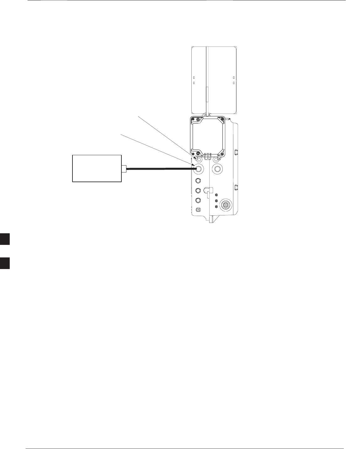
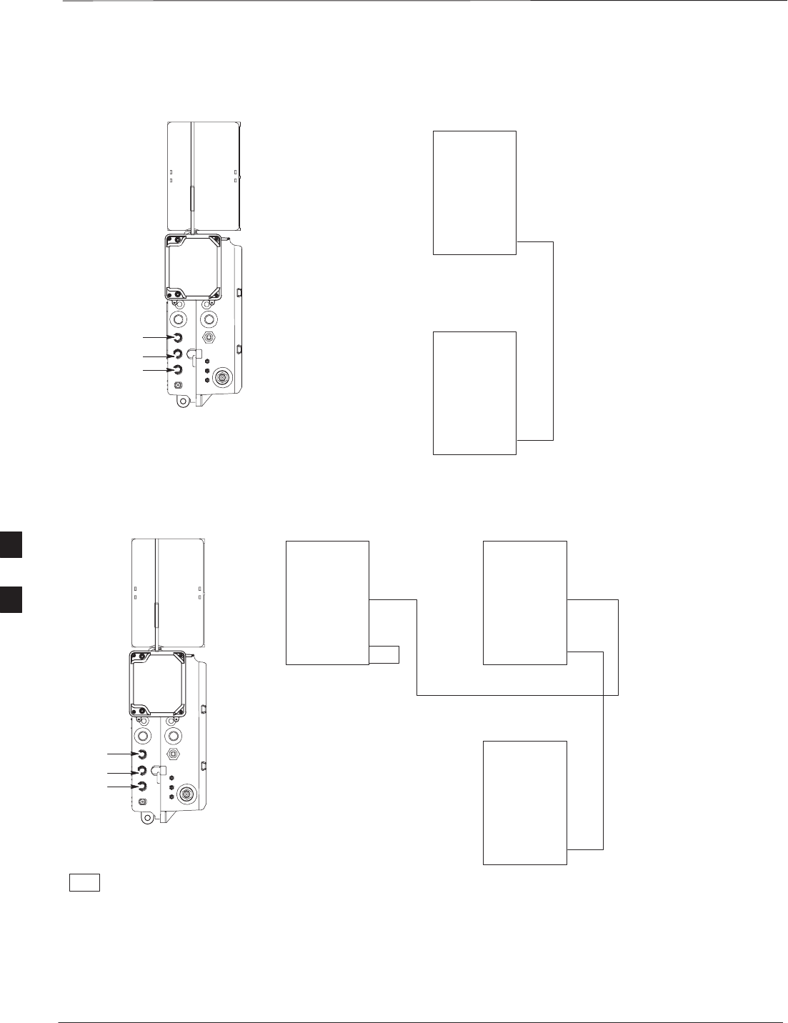
Procedure
Cable the units as shown in Figure 6-32, Figure 6-31 or Figure 6-30.
Make sure to terminate any unused connectors.
6
MIB Cabling for Multi–Unit Configurations – continued
PRELIMINARY
SCt300 BTS Hardware Installation, ATP and FRU Procedures DEC 2000
6-42
Figure 6-30: MIB Cabling for Two Units
MICROCELL SHOWN
MIB C
MIB B
MIB A
UNIT 1
UNIT 2
MIB C
MIB B
MIB A
MIB C
MIB B
MIB A
E/1 MIB (MICROCELL)
H/1 MIB (PICOCELL)
K/1 MIB (MICROCELL/CUBICLE)
L/1 MIB (PICOCELL/CUBICLE)
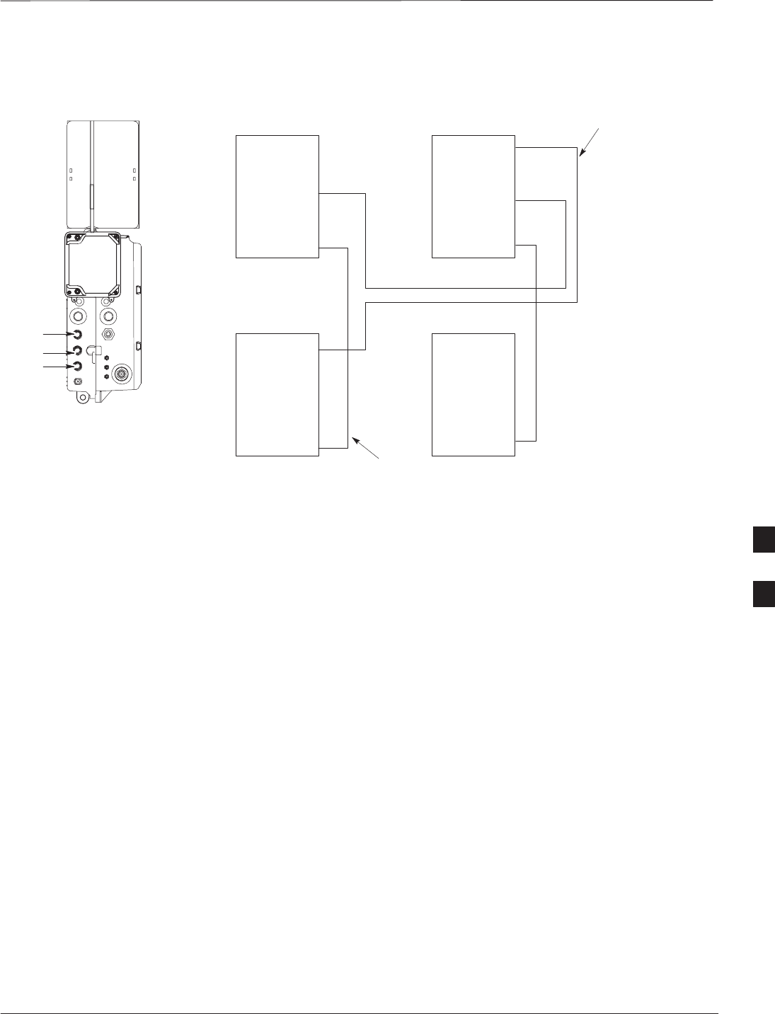
Figure 6-31: MIB Cabling for Three Units
MICROCELL SHOWN
MIB C
MT = MIB TERMINATOR
KEY
MIB B
MIB A
UNIT 1UNIT 3
UNIT 2
MIB C
MIB B
MIB A
MIB C
MIB B
MIB A
MIB C
MIB B
MIB A
MT
NOTE 1: NO MIB
TERMINATORS ARE USED ON
PICOCELLS
NOTE 2: MIB TERMINATOR
USED ON MICROCELL MIB A
CONNECTOR ONLY
E/1 MIB (MICROCELL)
H/1 MIB (PICOCELL)
K/1 MIB (MICROCELL/CUBICLE)
L/1 MIB (PICOCELL/CUBICLE)
F/1 MIB (MICRO/PICO)
I/1 MIB (MICRO/PICO)
6
MIB Cabling for Multi–Unit Configurations – continued
DEC 2000 6-43
SCt300 BTS Hardware Installation, ATP and FRU Procedures
PRELIMINARY
Figure 6-32: MIB Cabling for Four Units
MICROCELL SHOWN
MIB C
UNIT 1UNIT 3
UNIT 2UNIT 4
MIB B
MIB A
MIB C
MIB B
MIB A
MIB C
MIB B
MIB A
MIB C
MIB B
MIB A
MIB C
MIB B
MIB A
NOTES:
1. NO MIB TERMINATORS ARE USED
ON PICOCELLS
2. MIB A BETWEEN UNITS 3 AND 4
DOES NOT EXIST ON PICOCELL
E/1 MIB (MICROCELL)
H/1 MIB (PICOCELL)
K/1 MIB (MICROCELL/CUBICLE)
L/1 MIB (PICOCELL/CUBICLE)
E/1 MIB (MICROCELL)
H/1 MIB (PICOCELL)
K/1 MIB (MICROCELL/CUBICLE)
L/1 MIB (PICOCELL/CUBICLE)
(SEE NOTE 2)
G/1 MIB (MICROCELL/PICOCELL)
J/1 MIB (PICOCELL)
F/1 MIB (MICRO/PICO)
I/1 MIB (MICRO/PICO)
6

SU Cabling
PRELIMINARY
SCt300 BTS Hardware Installation, ATP and FRU Procedures DEC 2000
6-44
Objective
The objective of this procedure is to install the SU cable on one or more
units.
Cable Labels
The cable designations are referenced to Table 6-5 in the “Cable
Description” area of this chapter.
Tools and Equipment
Required tools
A 5/16–in. breakaway torque wrench is required to do this procedure.
Motorola parts
SU Distribution Terminators, SMA (Motorola Part Number
0187683C02) are required to do this procedure.
Table 6-30 provides the quantitity and description of the SU cable used
for a single–unit installation.
Table 6-30: Cables Needed for SU Connections
Cable Qty. Part Number Description
P 1 3087416C19 SU cable, 105 mm
Q N/A* 3088120C01 SU RF cable, long (part of kits SGEN4062A, SGEN4061A,
SGEN4064A, SGEN4063A, SGEN4066A, SGEN4065A,
SGEN4068A, SGEN4067A, SGEN4070A and SGEN4069A).
R N/A* 3088120C02 SU RF cable, short (part of kits SGEN4066A and SGEN4065A)
*Quantity of cables depends upon system configuration. Refer to “Motorola Kits for Multi–Unit Installations”
for more information.
Motorola kits
Table 6-31 through Table 6-40 gives the Motorola Kit numbers, cable
descriptions and part numbers for the Motorola kits required to perform
the SU cabling on a multi–unit installation. Several kits are available
depending upon the carrier installation.
Table 6-31: Microcell Expansion Kit for Units 1 to 2 Short MIB A (Cubicle) – T448AL
Cable Qty. Motorola Part
Number Description
n/a 2 5882106P01 50 Ohm Antenna Terminator
A 1 3087701C02 Ground cable, 8 -AWG, insulated copper wire. Requires one ring lug
connector.
K 1 3087707C09 MIB A cable (short, 1m; micro)
Q 1 3088120C01 Long SU Cable
6

SU Cabling – continued
DEC 2000 6-45
SCt300 BTS Hardware Installation, ATP and FRU Procedures
PRELIMINARY
Table 6-32: Microcell Expansion Kit for Units 1 to 2 Long MIB A (Non–Cubicle) – T448AM
Cable Qty. Motorola Part
Number Description
n/a 2 5882106P01 50 Ohm Antenna Terminator
A 1 3087701C02 Ground cable, 8 -AWG, insulated copper wire. Requires one ring lug
connector.
E 1 3087707C03 MIB A cable (current, 2m; micro)
Q 1 3088120C01 Long SU Cable
Table 6-33: Picocell Expansion Kit for Units 1 to 2 Short MIB A (Cubicle) – T448AN
Cable Qty. Motorola Part
Number Description
A 1 3087701C02 Ground cable, 8 -AWG, insulated copper wire. Requires one ring lug
connector.
L 1 3087707C10 MIB A cable (short 1m; pico)
Q 1 3088120C01 Long SU Cable
Table 6-34: Picocell Expansion Kit for Units 1 to 2 Long MIB A (Non–Cubicle) – T448AP
Cable Qty. Motorola Part
Number Description
A 1 3087701C02 Ground cable, 8 -AWG, insulated copper wire. Requires one ring lug
connector.
H 1 3087707C06 MIB A cable (long, 2m; pico)
Q 1 3088120C01 Long SU Cable
Table 6-35: Microcell/Picocell Expansion Kit for Units 2 to 3 Current 2m MIB B – T448AR
Cable Qty. Motorola Part
Number Description
A 1 3087701C02 Ground cable, 8 -AWG, insulated copper wire. Requires one ring lug
connector.
F 1 3087707C04 MIB B cable (current, 2m)
Q 2 3088120C01 Long SU Cable
R 2 3088120C02 Short SU RF Cable
n/a 2 5688123C01 SU Splitter
n/a 2 8009573X06 Lightning arrestor
6

SU Cabling – continued
PRELIMINARY
SCt300 BTS Hardware Installation, ATP and FRU Procedures DEC 2000
6-46
Table 6-36: Microcell/Picocell Expansion Kit for Units 2 to 3 Long 5m MIB B – T448AS
Cable Qty. Motorola Part
Number Description
A 1 3087701C02 Ground cable, 8 -AWG, insulated copper wire. Requires one ring lug
connector.
I 1 3087707C07 MIB B cable (long, 5m)
Q 2 3088120C01 Long SU RF Cable
R 2 3088120C02 Short SU RF Cable
n/a 2 5688123C01 SU Splitter
n/a 2 8009573X06 Lightning arrestor
Table 6-37: Microcell/Picocell Expansion Kit for Units 3 to 4 Current 2m MIBs B and C – T448AT
Cable Qty. Motorola Part
Number Description
A 1 3087701C02 Ground cable, 8 -AWG, insulated copper wire. Requires one ring lug
connector.
n/a 2 5882106P01 50 Ohm Antenna Terminator
E 1 3087707C03 MIB A cable (current, 2m; micro)
F 1 3087707C04 MIB B cable (current, 2m)
G 2 3087707C05 MIB C cable (current, 2m)
Q 1 3088120C01 Long SU RF Cable
Table 6-38: Microcell/Picocell Expansion Kit for Units 3 to 4 Longer 5M MIBs B and C – T448AU
Cable Qty. Motorola Part
Number Description
n/a 2 5882106P01 50 Ohm Antenna Terminator
A 1 3087701C02 Ground cable, 8 -AWG, insulated copper wire. Requires one ring lug
connector.
E 1 3087707C03 MIB A cable (current, 2m; micro)
I 1 3087707C07 MIB B cable (long, 5m)
J 2 3087707C08 MIB C cable (long, 5m)
Q 1 3088120C01 Long SU RF Cable
6

SU Cabling – continued
DEC 2000 6-47
SCt300 BTS Hardware Installation, ATP and FRU Procedures
PRELIMINARY
Table 6-39: Picocell Expansion Kit for Units 3 to 4 Current 2M MIBs B and C – T448AV
Cable Qty. Motorola Part
Number Description
n/a 2 5882106P01 50 Ohm Antenna Terminator
A 1 3087701C02 Ground cable, 8 -AWG, insulated copper wire. Requires one ring lug
connector.
E 1 3087707C03 MIB A cable (current, 2m; micro)
F 1 3087707C04 MIB B cable (long, 2m)
G 2 3087707C05 MIB C cable (long, 2m)
Q 1 3088120C01 Long SU RF Cable
Table 6-40: Picocell Expansion Kit for Units 3 to 4 Longer 5M MIBs B and C – T448AW
Cable Qty. Motorola Part
Number Description
A 1 3087701C02 Ground cable, 8 -AWG, insulated copper wire. Requires one ring lug
connector.
H 1 3087707C06 MIB A cable (long, 2m; pico)
I 1 3087707C07 MIB B cable (long, 5m)
J 2 3087707C08 MIB C cable (long, 5m)
Q 1 3088120C01 Long SU RF Cable
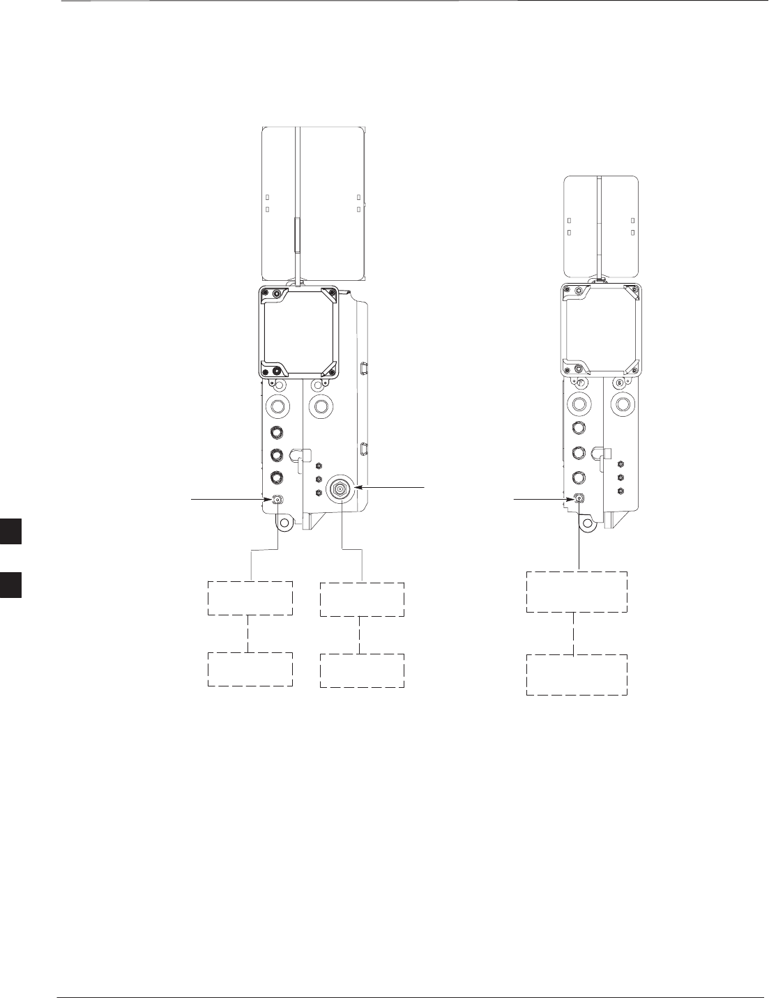
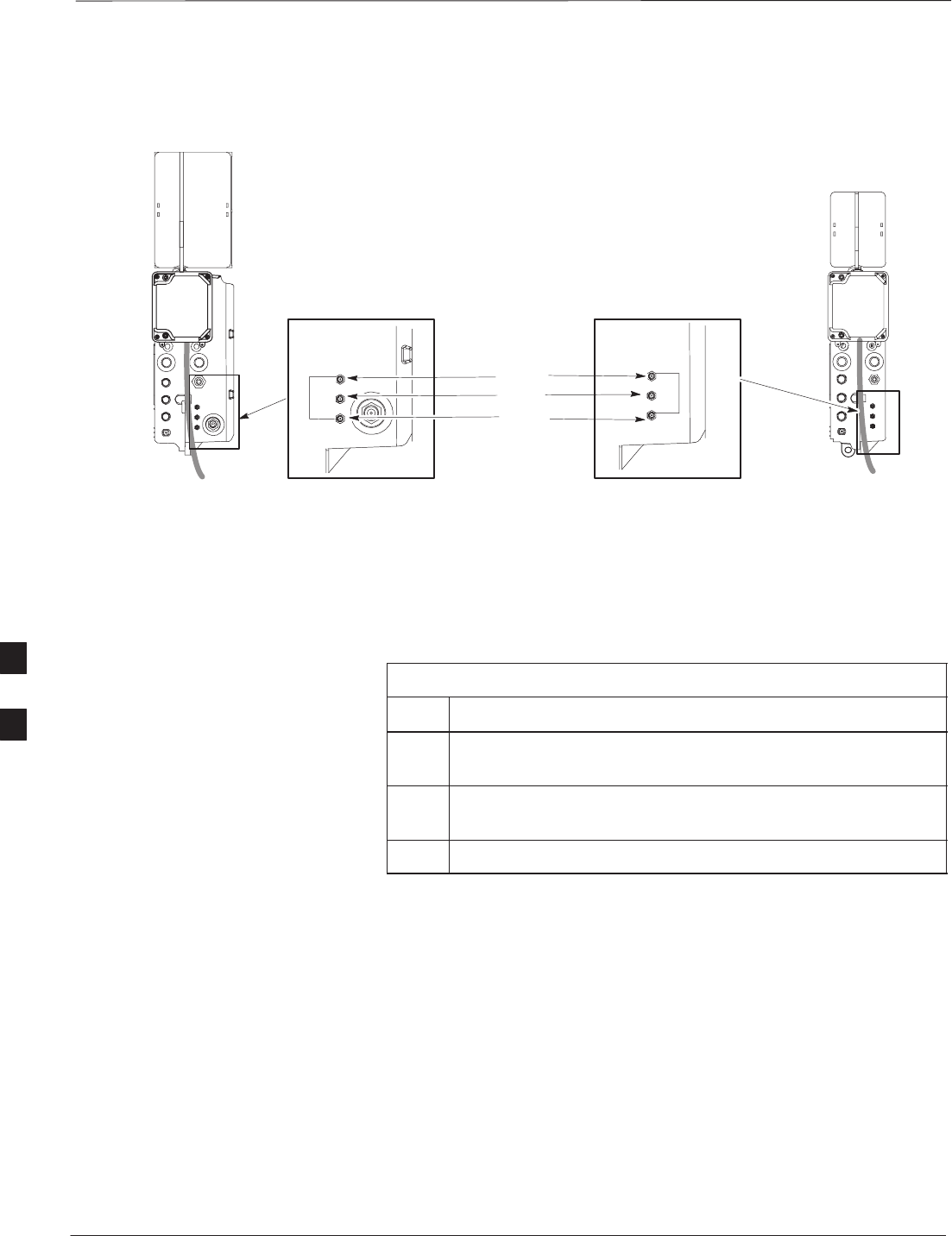
Procedure to Install SU Cabling
for Single Unit
Table 6-41 gives the procedure to install the SU cable on one MicroCell
or Picocell. Figure 6-33 shows the location of the cable connectors on
the unit.
Table 6-41: Install the SU Cable on One MicroCell or PicoCell
Step Action
1Connect cable P to the SU RF and the SU1 connectors of the
unit.
2Torque the connectors at each end of the cable to 9 in–lb. Use
a 5/16–in. breakaway torque wrench.
6
SU Cabling – continued
PRELIMINARY
SCt300 BTS Hardware Installation, ATP and FRU Procedures DEC 2000
6-48
Figure 6-33: SU Cabling Details for Single MicroCell or Picocell
SU RF
SU 2
SU 1
HH
MICROCELL PICOCELL
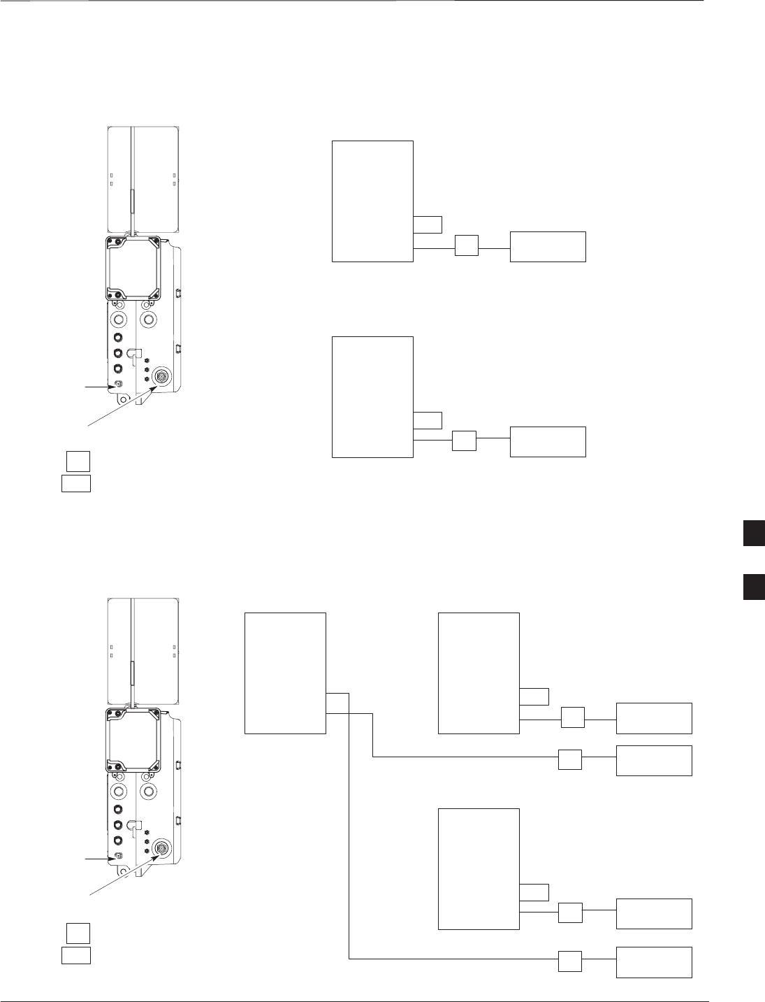
SU Cabling for Multi–Unit
Configurations
Table 6-42 gives the procedure to install the SU cabling for Multi–unit
configurations. Figure 6-34, Figure 6-35 and Figure 6-36 show the SU
cabling for multi–unit configurations.
Table 6-42: Install SU Cabling for Multi–BTS Configurations
Step Action
1Connect cable H to the appropriate SU connectors as shown
in Figure 6-34, Figure 6-35 and Figure 6-36.
2Torque the connectors at each end of the cable to 9 in–lb. Use
a 5/16–in. breakaway torque wrench.
3Terminate all unused SU connectors.
6
SU Cabling – continued
DEC 2000 6-49
SCt300 BTS Hardware Installation, ATP and FRU Procedures
PRELIMINARY
Figure 6-34: SU Cabling Details for Two Units UNIT 1
UNIT 2
MICROCELL
SHOWN
SU(2)
SU(1)
SU RF
SU(2)
SU(1)
SU RF
SU(2)
SU(1)
SU RF
RFT =50 OHM RF TERMINATION
KEY
RFT
RFT
H
H
Figure 6-35: SU Cabling Details for Three Units
UNIT 1
UNIT 2
MICROCELL
SHOWN
SU(2)
SU(1)
SU RF
SU(2)
SU(1)
SU RF
SU(2)
SU(1)
SU RF
UNIT 3
SU(2)
SU(1)
SU RF
2X
RFT
2X
RFT =50 OHM RF TERMINATION
2X =SU SPLITTER
KEY
RFT
RFT
RFT
RFT
H
H
H
H
6
SU Cabling – continued
PRELIMINARY
SCt300 BTS Hardware Installation, ATP and FRU Procedures DEC 2000
6-50
Figure 6-36: SU Cabling Details for Four Units
UNIT 1
UNIT 2
MICROCELL
SHOWN
SU(2)
SU(1)
SU RF
SU(2)
SU(1)
SU RF
SU(2)
SU(1)
SU RF
UNIT 3
SU(2)
SU(1)
SU RF
2X
2X
2X = SU SPLITTER
KEY
UNIT 4
SU(2)
SU(1)
SU RF
RFT =50 OHM RF TERMINATION
RFT
RFT
RFT
RFT
RFT
RFT
H
H
H
H
H
H
6

Terminating Unused Connections
DEC 2000 6-51
SCt300 BTS Hardware Installation, ATP and FRU Procedures
PRELIMINARY
Objective
The objective of this procedure is to terminate any unused connections.
Terminate all unused connections.
IMPORTANT
*
Termination List (MicroCell)
Table 6-43: Terminations of Unused Connectors
Connector Motorola Part # Description
AC Input 5887659C02 Terminator, AC
DC Input 5887659C04 Terminator, DC
MIB A 3009865S02 Terminator, MIB
SU Distribution 0187683C02 Terminator, SMA
MIB B, C 3009865S04 Cap, MIB
Termination List (PicoCell)
Table 6-44: Terminations of Unused Connectors
Connector Motorola Part # Description
AC Input 5887659C02 Terminator, AC
DC Input 5887659C04 Terminator, DC
MIB A, B, C 3009865S04 Cap, MIB
SU Distribution 0187683C01 Terminator, SMA
Procedure
The unit is shipped with the above terminators. Verify that a terminator
is on each unused connector. Tighten the SMA terminators using a
5/16 Breakaway 9 in. lb. Hand tighten all other terminators.
6

Powering on Unit and Mounting the Solar Cover
PRELIMINARY
SCt300 BTS Hardware Installation, ATP and FRU Procedures DEC 2000
6-52
Objective
The objective of this procedure is to power on the unit and mount the
solar cover on the chassis.
You May Want to Wait
Do not mount the front solar cover on the unit if you wish to perform the
Acceptance Test Procedures (ATP). Otherwise, mount the front solar
cover until you perform the ATP.
Tools Required
The following tamper–resistant keys are required to do this procedure.
SKey for tamper–resistant stud (provided) for the solar cover.
SKey for tamper–resistant locks (provided) for the Primary Surge
Suppressor.
Procedure to Power On Unit
and Mount Solar Cover
Refer to the procedure in Table 6-45 to power on the unit and mount the
solar cover.
Table 6-45: Procedure to Power on the Unit and Mount the Solar
Cover
Step Action
1n WARNING
Make sure the unit is properly grounded and that all
connections are connected before powering on unit.
If l i AC 2 If l i AC
If not applying AC power, go to step 2. If applying AC
power, push down on the AC power breaker until it clicks and
remains down. The white collar on the breaker is not visible
when the breaker is closed.
2If not applying DC power or providing for battery backup, go
to step 3. If applying DC power or have short or long
duration batteries present, push down on the DC power
breaker until it clicks and remains down. The white collar on
the breaker is not visible when the breaker is closed.
3Position the solar cover so the cooling vents are at the top and
place the solar cover on the unit. Use the key to tighten the
four tamper–resistant studs (two on each side). Refer to
Figure 6-37.
Procedure to Power On Surge
Suppressor, Unit and Mount
Solar Cover
If your BTS is equipped with the Primary Surge Suppressor, refer to the
procedure in Table 6-46 to power on the unit and mount the solar cover.
6

Powering on Unit and Mounting the Solar Cover – continued
DEC 2000 6-53
SCt300 BTS Hardware Installation, ATP and FRU Procedures
PRELIMINARY
Table 6-46: Procedure to Power on the Surge Suppressor, the Unit, and
Mount the Solar Cover
Step Action
1If closed, open the front cover of the Primary Surge
Suppressor. Use the tamper–resistant key and turn both the
locks counter–clockwise. Refer to Figure 6-37.
2If not applying AC power, go to step 6. If applying AC
power, push the main AC power breaker on the Surge
Suppressor to the “On“ position. Refer to Figure 6-38.
3Push the AC power breakers for each individual carrier to the
“On” position. All unused power breakers must be in the
“Off” position.
4Close the Primary Surge Suppressor door. Use the
tamper–resistant key to turn the locks clockwise to the
“Locked” position.
5Push down on the AC power breaker on the unit until it clicks
and remains down. The white collar on the breaker is not
visible when the breaker is closed.
6If not applying DC power or providing for battery backup, go
to step 7. If applying DC power or have short or long
duration batteries present, push down on the DC power
breaker until it clicks and remains down. The white collar on
the breaker is not visible when the breaker is closed.
7Position the solar cover so the cooling vents are at the top and
place the solar cover on the unit. Use the tamper–resistant
key to tighten the four screws (two on each side) to 2.2 N–M.
Refer to Figure 6-39.
6
Powering on Unit and Mounting the Solar Cover – continued
PRELIMINARY
SCt300 BTS Hardware Installation, ATP and FRU Procedures DEC 2000
6-54
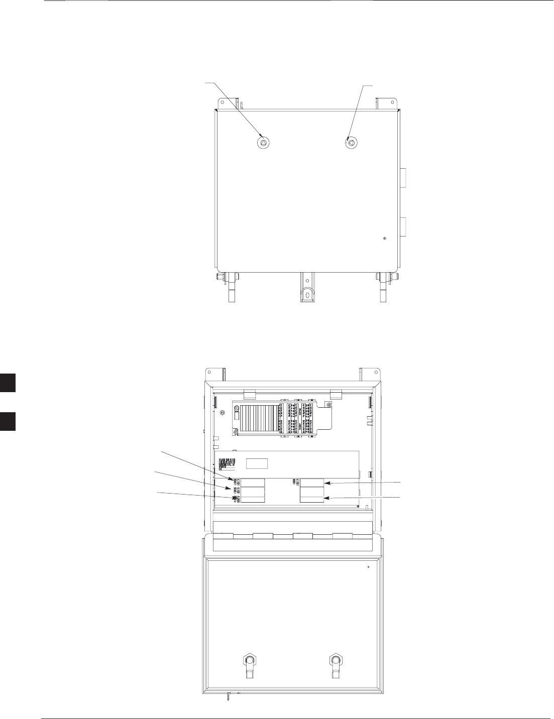
Figure 6-37: Lock Positions on Primary Surge Suppressor
LATCHED POSITION UNLATCHED POSITION
Figure 6-38: Location of AC Power Breakers on Primary Surge Suppressor
AC POWER BREAKER
CARRIER 1
AC POWER BREAKER
CARRIER 2
AC POWER BREAKER
CARRIER 3
AC POWER BREAKER
CARRIER 4
MAIN INPUT BREAKER
NOTE: INTERNAL CABLING
NOT SHOWN FOR CLARITY
6

Powering on Unit and Mounting the Solar Cover – continued
DEC 2000 6-55
SCt300 BTS Hardware Installation, ATP and FRU Procedures
PRELIMINARY
Figure 6-39: Front Solar Cover
FRONT COVER
MOUNTING
SCREWS (4)
6

Site Cleanup
PRELIMINARY
SCt300 BTS Hardware Installation, ATP and FRU Procedures DEC 2000
6-56
Remove protective covering
Remove any antistatic plastic or cloth sheeting that was used to cover the
equipment.
Lighting fixtures
Remove the masking tape from the fluorescent light fixtures.
Tools
Place all hand and power tools in the installation tool kit or other
appropriate place. Note any tools that need replacement, cleaning, or
adjustment.
Materials
Place any leftover materials in a location specified by the site manager.
Remove debris
Remove any packing material.
Ensure that all scrap materials have been removed from any tables or
stands.
Clean/sweep the floor. Ensure that all alignment marks have been
removed.
Environment
Remove any temporary weather protection used for installation.
Check that all covers are in place.
Check that the power connections are tight.
Organize any items (manuals, materials, etc.) left on site and place them
in a location specified by the site manager.
Check that the unit lock is secure and key is removed.
Check that solar cover is secure.
Verify that cabling is properly secured between unit and enclosures.
6

Installation Completion Checklist
DEC 2000 6-57
SCt300 BTS Hardware Installation, ATP and FRU Procedures
PRELIMINARY
Directions
Fill out the installation completion checklist and make any necessary
copies. You may copy this check sheet as needed.
6

Installation Completion Checklist – continued
PRELIMINARY
SCt300 BTS Hardware Installation, ATP and FRU Procedures DEC 2000
6-58
Installation completion
checklist
Date Hardware Installation Completed: ________________________
Site:_______________________________________________________
Serial Number(s):__________________________
__________________________________________________________
Checklist Completed By:_____________________________________
Checklist Reviewed By:______________________________________
Table 6-47: Installation Completion Checklist
Status No. Item Notes
1Air flow clearance requirements are met.
2Equipment is not damaged.
3Mounting bracket is level and secure.
4Back solar cover (if applicable) is securely
attached to the mounting bracket.
5RGPS head and mast are secure.
6RGPS head has a clear view of the sky and is
not in a location which accumulates debris.
Make sure the RGPS is located away from
the BTS transmit antenna.
7Mounting bracket is connected to the Master
ground.
8The connection to the AC source is secure (if
applicable).
9The AC source is protected by a lightning
arrestor (if applicable).
10 The connection to the DC source is secure (if
applicable).
11 The connection to the battery is secure (if
applicable).
12 The connection to the auxiliary device is
secure (if applicable).
13 The antenna connections are secure.
14 The antenna cables are protected by lightning
arrestors (if applicable).
15 Customer input alarm connections are
complete between the Site I/O cable and the
Site I/O interface(s).
16 RGPS connections are complete between the
Site I/O cable and the Site I/O interface(s).
6

Installation Completion Checklist – continued
DEC 2000 6-59
SCt300 BTS Hardware Installation, ATP and FRU Procedures
PRELIMINARY
Table 6-47: Installation Completion Checklist
Status NotesItemNo.
17 Phone (modem) connections are complete
between the Site I/O cable and the Site I/O
interface(s).
18 Span connections are complete between the
Site I/O cable and the Site I/O interface(s).
19 Span, phone, and RGPS connections are
protected by lightning arrestors (if
applicable).
20 The RGPS/HSO cabling for multi–BTS
configurations is secure (if applicable).
21 The span line daisy chain cabling for
multi–BTS configurations is secure.
22 The RGPS ground lead is connected to the
BTS digital ground reference.
23 Fin covers are secure.
24 Installation hardware is removed.
25 The lock is in place and the key removed.
26 The site I/O junction box is secure.
27 The short–duration battery is secure (if
applicable).
28 The short–duration battery cable (DC input
cable) is secure (if applicable).
29 The earth ground connection is secure
between the site I/O junction box and the
mounting bracket.
30 The AC input cable is securely attached to the
AC input connector (if applicable).
31 The DC input cable is securely attached to the
DC input connector (if applicable).
32 The DC output cable is securely attached to
the DC output connector (if applicable).
33 The unit–to–unit SU cabling is secure (if
applicable).
34 The unit–to–unit MIB cabling is secure (if
applicable)
35 The antenna N–type connectors are securely
attached to the antenna A and B connectors
(if applicable).
6

Installation Completion Checklist – continued
PRELIMINARY
SCt300 BTS Hardware Installation, ATP and FRU Procedures DEC 2000
6-60
Table 6-47: Installation Completion Checklist
Status NotesItemNo.
36 All unused ports are properly terminated.
37 All cables are dressed and tied.
38 The external power source (AC or DC) is
active.
39 The AC and/or DC power breakers on the
BTS are engaged (pushed in).
40 The front solar cover is secure (if applicable).
41 The auxiliary device is switched on (if
applicable).
42 The site is cleaned, swept and trash removed.
43 The site specific documentation is present at
the site.
6

DEC 2000 SCt300 BTS Hardware Installation, ATP and FRU Procedures
PRELIMINARY
Chapter 7: Optimization and Optional Acceptance Test Procedures (ATP)
Table of Contents
ATP Overview 7-1. . . . . . . . . . . . . . . . . . . . . . . . . . . . . . . . . . . . . . . . . . . . . . . . . . .
Overview 7-1. . . . . . . . . . . . . . . . . . . . . . . . . . . . . . . . . . . . . . . . . . . . . . . .
BTS Preparation 7-2. . . . . . . . . . . . . . . . . . . . . . . . . . . . . . . . . . . . . . . . . . . . . . . . .
Overview 7-2. . . . . . . . . . . . . . . . . . . . . . . . . . . . . . . . . . . . . . . . . . . . . . . .
Tools Required 7-2. . . . . . . . . . . . . . . . . . . . . . . . . . . . . . . . . . . . . . . . . . . .
Remove Solar Cover 7-2. . . . . . . . . . . . . . . . . . . . . . . . . . . . . . . . . . . . . . .
BTS Power Up 7-2. . . . . . . . . . . . . . . . . . . . . . . . . . . . . . . . . . . . . . . . . . . .
Removing Diagnostic Access Cover Procedure 7-5. . . . . . . . . . . . . . . . . .
Test Equipment and LMF Connection 7-7. . . . . . . . . . . . . . . . . . . . . . . . . . . . . . . .
Overview 7-7. . . . . . . . . . . . . . . . . . . . . . . . . . . . . . . . . . . . . . . . . . . . . . . .
LMF to BTS Connection 7-7. . . . . . . . . . . . . . . . . . . . . . . . . . . . . . . . . . . .
Procedure 7-7. . . . . . . . . . . . . . . . . . . . . . . . . . . . . . . . . . . . . . . . . . . . . . . .
Test Equipment Connection 7-8. . . . . . . . . . . . . . . . . . . . . . . . . . . . . . . . . .
Connecting Test Equipment to the BTS and LMF 7-9. . . . . . . . . . . . . . . .
Connecting Advantest R3465 to BTS 7-9. . . . . . . . . . . . . . . . . . . . . . . . . .
Connecting the Communication Test Set and Power Meter to the LMF 7-13
Cable Configuration 7-14. . . . . . . . . . . . . . . . . . . . . . . . . . . . . . . . . . . . . . . .
BTS Configuration 7-15. . . . . . . . . . . . . . . . . . . . . . . . . . . . . . . . . . . . . . . . . . . . . . .
Objective 7-15. . . . . . . . . . . . . . . . . . . . . . . . . . . . . . . . . . . . . . . . . . . . . . . .
Creating a Named HyperTerminal Connection for
MMI Communication 7-15. . . . . . . . . . . . . . . . . . . . . . . . . . . . . . . . . . . . . .
Establishing an MMI Communication Session 7-17. . . . . . . . . . . . . . . . . . .
Programming Customer Operating Channel 7-17. . . . . . . . . . . . . . . . . . . . .
Synchronization Background 7-18. . . . . . . . . . . . . . . . . . . . . . . . . . . . . . . . .
Synchronization Configuration 7-19. . . . . . . . . . . . . . . . . . . . . . . . . . . . . . .
Synchronization Verification 7-20. . . . . . . . . . . . . . . . . . . . . . . . . . . . . . . . .
Location Coordinates 7-22. . . . . . . . . . . . . . . . . . . . . . . . . . . . . . . . . . . . . . .
BTS Software 7-24. . . . . . . . . . . . . . . . . . . . . . . . . . . . . . . . . . . . . . . . . . . . . . . . . . .
Objective 7-24. . . . . . . . . . . . . . . . . . . . . . . . . . . . . . . . . . . . . . . . . . . . . . . .
Install the LMF Program and BTS Binaries 7-24. . . . . . . . . . . . . . . . . . . . .
Create a Site–Specific BTS Directory 7-24. . . . . . . . . . . . . . . . . . . . . . . . . .
Start the LMF and Login to the BTS 7-24. . . . . . . . . . . . . . . . . . . . . . . . . . .
Update BTS Specific CDF File Device Load Version 7-25. . . . . . . . . . . . .
Download/Enable MAWI 7-26. . . . . . . . . . . . . . . . . . . . . . . . . . . . . . . . . . .
Cell Site Data File (CDF) 7-27. . . . . . . . . . . . . . . . . . . . . . . . . . . . . . . . . . .
7

Table of Contents – continued
PRELIMINARY
SCt300 BTS Hardware Installation, ATP and FRU Procedures DEC 2000
Test Equipment Setup 7-29. . . . . . . . . . . . . . . . . . . . . . . . . . . . . . . . . . . . . . . . . . . . .
Purpose 7-29. . . . . . . . . . . . . . . . . . . . . . . . . . . . . . . . . . . . . . . . . . . . . . . . .
Required Test Equipment 7-29. . . . . . . . . . . . . . . . . . . . . . . . . . . . . . . . . . .
Test Set Calibration Background 7-29. . . . . . . . . . . . . . . . . . . . . . . . . . . . . .
Purpose of Test set Calibration 7-30. . . . . . . . . . . . . . . . . . . . . . . . . . . . . . .
Selecting Test Equipment 7-30. . . . . . . . . . . . . . . . . . . . . . . . . . . . . . . . . . .
Manually Selecting Test Equipment in a Serial Connection Tab 7-30. . . . .
Automatically Selecting Test Equipment in a Serial Connection Tab 7-31. .
Calibrating Test Equipment 7-32. . . . . . . . . . . . . . . . . . . . . . . . . . . . . . . . . .
R3465 Calibration/GPIB Address & Clock Setup 7-33. . . . . . . . . . . . . . . .
Power Meter GPIB Setup 7-35. . . . . . . . . . . . . . . . . . . . . . . . . . . . . . . . . . .
Acceptance Test (ATP) Equipment Setup 7-36. . . . . . . . . . . . . . . . . . . . . . .
Test Equipment Selection 7-37. . . . . . . . . . . . . . . . . . . . . . . . . . . . . . . . . . . . . . . . . .
Objective 7-37. . . . . . . . . . . . . . . . . . . . . . . . . . . . . . . . . . . . . . . . . . . . . . . .
Prerequisites 7-37. . . . . . . . . . . . . . . . . . . . . . . . . . . . . . . . . . . . . . . . . . . . . .
Procedure 7-37. . . . . . . . . . . . . . . . . . . . . . . . . . . . . . . . . . . . . . . . . . . . . . . .
Power Meter Calibration 7-38. . . . . . . . . . . . . . . . . . . . . . . . . . . . . . . . . . . . . . . . . . .
Objective 7-38. . . . . . . . . . . . . . . . . . . . . . . . . . . . . . . . . . . . . . . . . . . . . . . .
Prerequisites 7-38. . . . . . . . . . . . . . . . . . . . . . . . . . . . . . . . . . . . . . . . . . . . . .
Procedure 7-38. . . . . . . . . . . . . . . . . . . . . . . . . . . . . . . . . . . . . . . . . . . . . . . .
Test Cable Calibration 7-39. . . . . . . . . . . . . . . . . . . . . . . . . . . . . . . . . . . . . . . . . . . .
Background 7-39. . . . . . . . . . . . . . . . . . . . . . . . . . . . . . . . . . . . . . . . . . . . . .
Purpose 7-39. . . . . . . . . . . . . . . . . . . . . . . . . . . . . . . . . . . . . . . . . . . . . . . . .
Automated Cable Calibration Procedure 7-40. . . . . . . . . . . . . . . . . . . . . . . .
Create CAL File 7-42. . . . . . . . . . . . . . . . . . . . . . . . . . . . . . . . . . . . . . . . . . . . . . . . .
Overview 7-42. . . . . . . . . . . . . . . . . . . . . . . . . . . . . . . . . . . . . . . . . . . . . . . .
Create CAL File 7-42. . . . . . . . . . . . . . . . . . . . . . . . . . . . . . . . . . . . . . . . . . .
Procedure 7-43. . . . . . . . . . . . . . . . . . . . . . . . . . . . . . . . . . . . . . . . . . . . . . . .
RF Path Audit 7-44. . . . . . . . . . . . . . . . . . . . . . . . . . . . . . . . . . . . . . . . . . . . . . . . . . .
Test Equipment Setup 7-44. . . . . . . . . . . . . . . . . . . . . . . . . . . . . . . . . . . . . .
Transmit (TX) Audit 7-44. . . . . . . . . . . . . . . . . . . . . . . . . . . . . . . . . . . . . . .
Acceptance Tests 7-46. . . . . . . . . . . . . . . . . . . . . . . . . . . . . . . . . . . . . . . . . . . . . . . . .
TX Test Objective 7-46. . . . . . . . . . . . . . . . . . . . . . . . . . . . . . . . . . . . . . . . .
TX Tests to be Performed 7-46. . . . . . . . . . . . . . . . . . . . . . . . . . . . . . . . . . .
RX Test Objective 7-47. . . . . . . . . . . . . . . . . . . . . . . . . . . . . . . . . . . . . . . . .
RX Test to be Performed 7-47. . . . . . . . . . . . . . . . . . . . . . . . . . . . . . . . . . . .
CDMA Operating Frequency Programming Information – North American
PCS Bands 7-48. . . . . . . . . . . . . . . . . . . . . . . . . . . . . . . . . . . . . . . . . . . . . . . . . . . . .
Introduction 7-48. . . . . . . . . . . . . . . . . . . . . . . . . . . . . . . . . . . . . . . . . . . . . .
1900 MHz PCS Channels 7-48. . . . . . . . . . . . . . . . . . . . . . . . . . . . . . . . . . .
Calculating 1900 MHz Center Frequencies 7-49. . . . . . . . . . . . . . . . . . . . . .
800 MHz CDMA Channels 7-51. . . . . . . . . . . . . . . . . . . . . . . . . . . . . . . . . .
Calculating 800 MHz Center Frequencies 7-51. . . . . . . . . . . . . . . . . . . . . . .
TX & RX Acceptance Tests 7-53. . . . . . . . . . . . . . . . . . . . . . . . . . . . . . . . . . . . . . . .
TX ATP Test 7-53. . . . . . . . . . . . . . . . . . . . . . . . . . . . . . . . . . . . . . . . . . . . .
7

Table of Contents – continued
DEC 2000 SCt300 BTS Hardware Installation, ATP and FRU Procedures
PRELIMINARY
Prerequisites 7-53. . . . . . . . . . . . . . . . . . . . . . . . . . . . . . . . . . . . . . . . . . . . . .
TX Tests Using Backup Synchronization (Sites Equipped With GPS) 7-53.
RX ATP Test 7-55. . . . . . . . . . . . . . . . . . . . . . . . . . . . . . . . . . . . . . . . . . . . .
Generate an ATP Report 7-60. . . . . . . . . . . . . . . . . . . . . . . . . . . . . . . . . . . . . . . . . . .
Background 7-60. . . . . . . . . . . . . . . . . . . . . . . . . . . . . . . . . . . . . . . . . . . . . .
ATP Report 7-60. . . . . . . . . . . . . . . . . . . . . . . . . . . . . . . . . . . . . . . . . . . . . .
Copy LMF CAL File to CBSC 7-61. . . . . . . . . . . . . . . . . . . . . . . . . . . . . . . . . . . . .
Overview 7-61. . . . . . . . . . . . . . . . . . . . . . . . . . . . . . . . . . . . . . . . . . . . . . . .
Copying CAL Files from LMF to a Diskette 7-61. . . . . . . . . . . . . . . . . . . .
Copying CAL Files from Diskette to the CBSC 7-62. . . . . . . . . . . . . . . . . .
Prepare to Leave the Site 7-63. . . . . . . . . . . . . . . . . . . . . . . . . . . . . . . . . . . . . . . . . .
Removing External Test Equipment 7-63. . . . . . . . . . . . . . . . . . . . . . . . . . .
Reset and Initialize Site Remotely 7-63. . . . . . . . . . . . . . . . . . . . . . . . . . . . .
Bringing BTS into Service with the CDMA LMF 7-63. . . . . . . . . . . . . . . .
Terminating LMF Session/Removing Terminal 7-64. . . . . . . . . . . . . . . . . .
Replace Diagnostic Access Cover 7-65. . . . . . . . . . . . . . . . . . . . . . . . . . . . .
Replace Solar Cover 7-65. . . . . . . . . . . . . . . . . . . . . . . . . . . . . . . . . . . . . . .
7

Table of Contents – continued
PRELIMINARY
SCt300 BTS Hardware Installation, ATP and FRU Procedures DEC 2000
Notes
7

ATP Overview
DEC 2000 7-1
SCt300 BTS Hardware Installation, ATP and FRU Procedures
PRELIMINARY
Overview
The purpose of this procedure is to outline the optimization and ATP
after a BTS installation. Calibration of the BTS is performed in the
factory and is not required. The ATP is also performed in the factory
and is optional.
All the procedures in this chapter are to be performed with the BTS out
of service or under LMF control. If necessary, refer to the “Shut Down
and Restoring BTS Signaling” procedure in Chapter 7.
For a complete listing of the required tools and equipment, refer to the
“ATP Tools and Equipment” list in Chapter 1.
7

BTS Preparation
PRELIMINARY
SCt300 BTS Hardware Installation, ATP and FRU Procedures DEC 2000
7-2
Overview
The purpose of this procedure is to prepare the BTS for the ATP. This
procedure consists of:
1. Solar Cover Removal
2. BTS Power Up
3. Diagnostic Access Cover Removal
Tools Required
The following tools and materials are necessary to do this procedure:
STorque driver wrench, 1/4–in. hex female drive, 0–10 N–M
ST20 Torx tamper bit
Remove Solar Cover
If you did not mount the solar cover during the unit installation, then this
procedure is not necessary.
Procedure
Remove the four captive screws (two on each side) that hold the front
solar cover. Refer to Figure 7-1.
Figure 7-1: Front Solar Cover (MicroCell Illustrated)
FRONT COVER
CAPTIVE SCREWS
CAPTIVE SCREWS
BTS Power Up
Figure 7-2 shows the location of the AC and DC Power breakers on the
Microcell unit. Both the AC and DC breakers must be pushed in to
power up the unit.
7
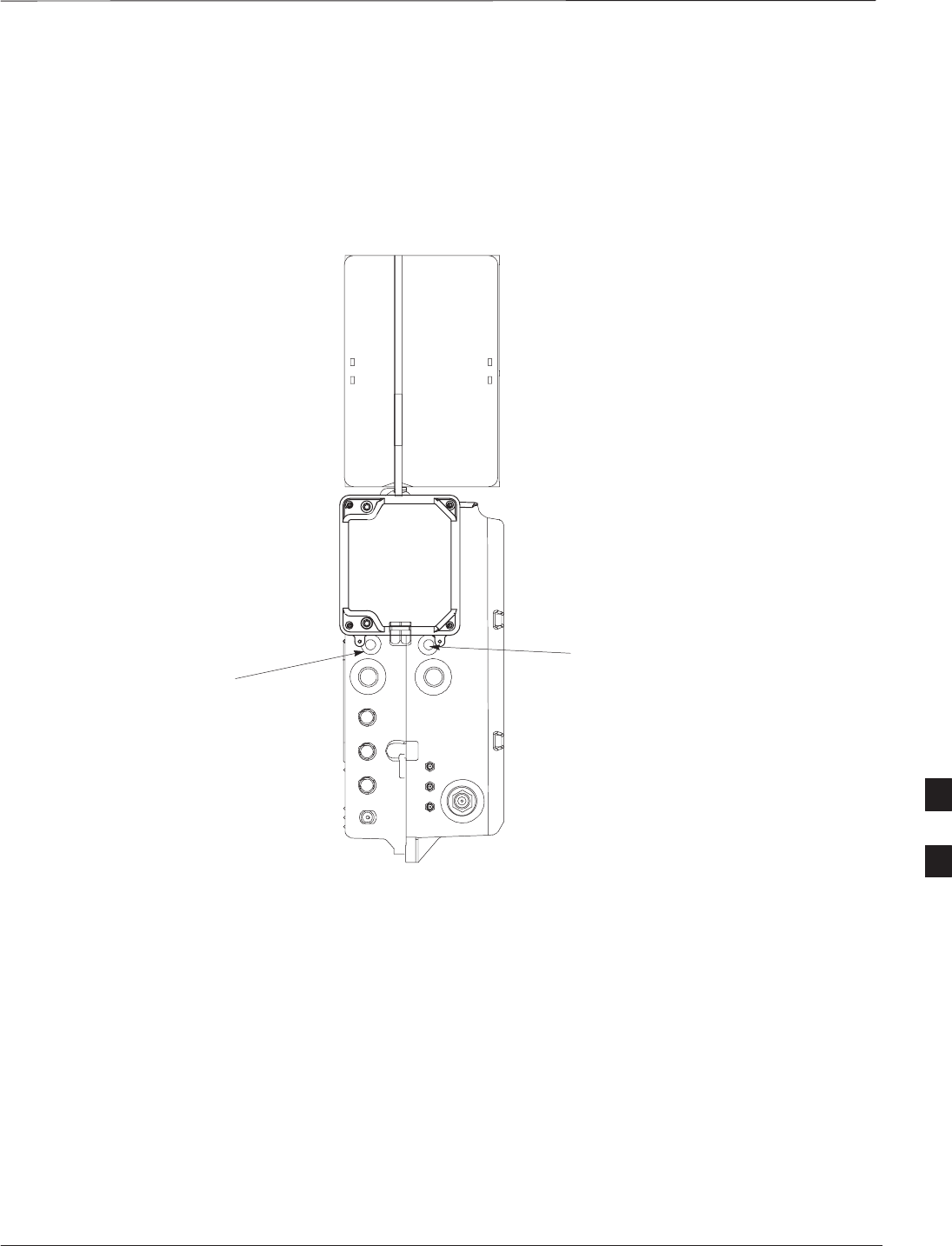
BTS Preparation – continued
DEC 2000 7-3
SCt300 BTS Hardware Installation, ATP and FRU Procedures
PRELIMINARY
Figure 7-3 shows the location of the AC power breakers inside the
optional Primary Surge Suppressor. The AC breakers must be closed
before you power up the Microcell or Picocell unit.
Figure 7-2: Location of AC and DC Power Breakers
AC POWER BREAKER
DC POWER BREAKER
0182–O_IL.doc
MICROCELL SHOWN
7
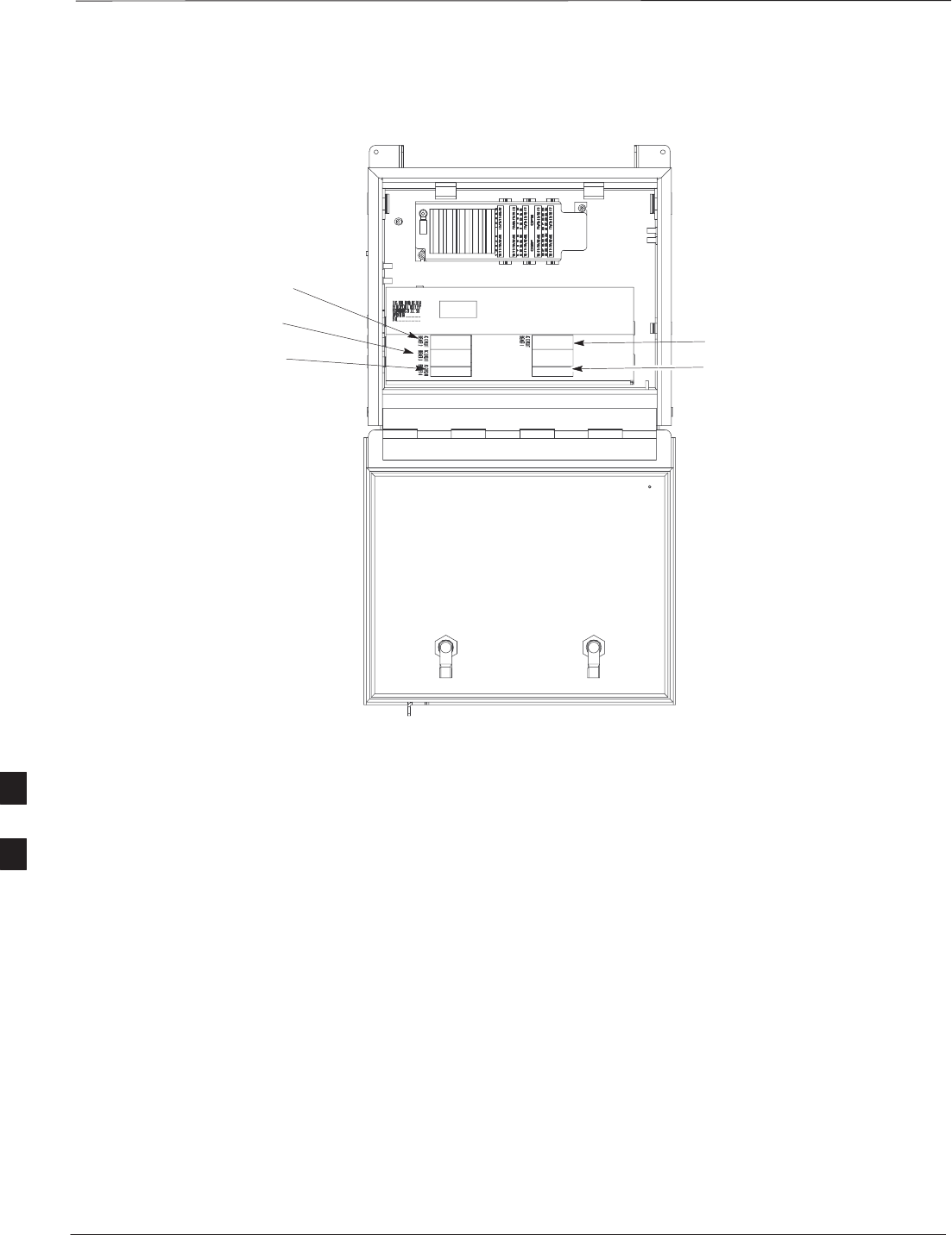
BTS Preparation – continued
PRELIMINARY
SCt300 BTS Hardware Installation, ATP and FRU Procedures DEC 2000
7-4
Figure 7-3: Location of AC Power Breakers Inside Primary Surge Suppressor
AC POWER BREAKER
CARRIER 1
AC POWER BREAKER
CARRIER 2
AC POWER BREAKER
CARRIER 3
AC POWER BREAKER
CARRIER 4
MAIN INPUT BREAKER
7
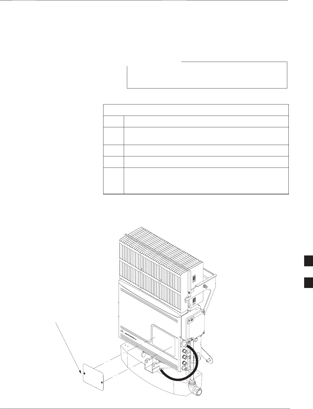
BTS Preparation – continued
DEC 2000 7-5
SCt300 BTS Hardware Installation, ATP and FRU Procedures
PRELIMINARY
Removing Diagnostic Access
Cover Procedure
The screws are captivated. Do not attempt to remove them
from the cover.
NOTE
Table 7-1: Procedure for Removing Diagnostic Access Cover
Step Action
1Using a T20 Torx tamper bit, loosen the two tamper resistant
M4 screws holding the cover. See Figure 7-4.
2Gently tap the cover to loosen if required.
3Remove the cover and set inside a secure place.
NOTE
The 19 MHz and 2 SEC connectors should not be terminated
with a 50 ohm terminator.
Figure 7-4: How To Remove The Diagnostic Access Cover (Microcell shown)
SCREWS IN DIAGNOSTIC
ACCESS COVER ARE CAPTIVE
7
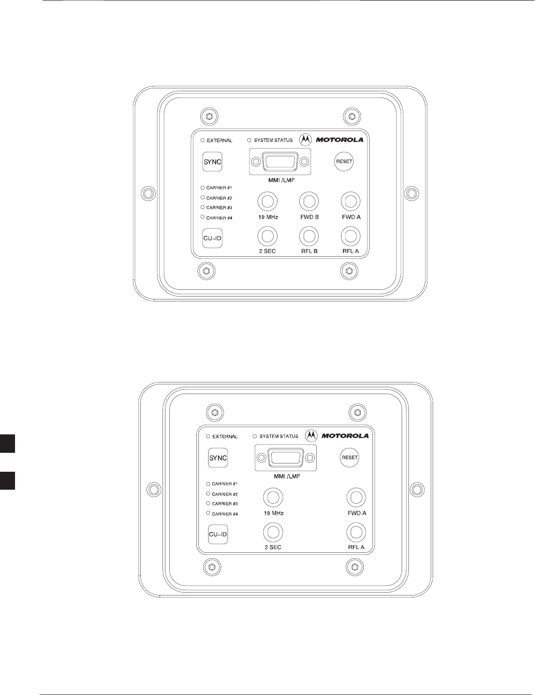
BTS Preparation – continued
PRELIMINARY
SCt300 BTS Hardware Installation, ATP and FRU Procedures DEC 2000
7-6
Figure 7-5: Detail Location of the Diagnostic Access Area for MicroCell
0181–O_IL.doc
Figure 7-6: Detail Location of the Diagnostic Access Area for PicoCell
7
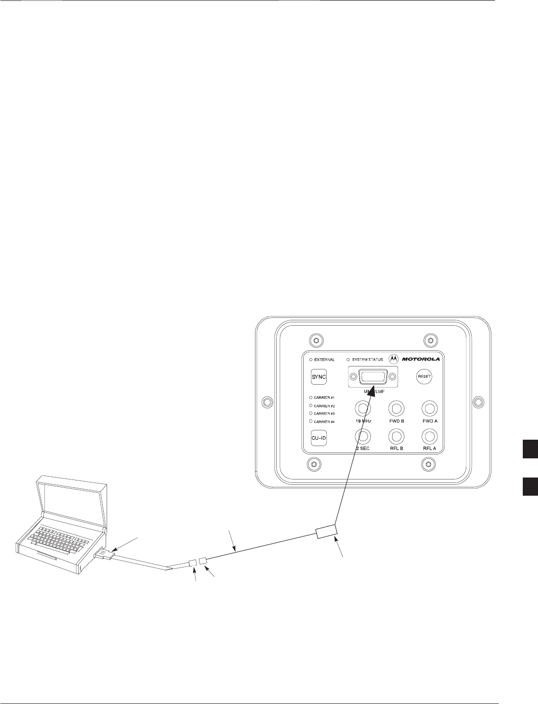
Test Equipment and LMF Connection
DEC 2000 7-7
SCt300 BTS Hardware Installation, ATP and FRU Procedures
PRELIMINARY
Overview
This procedure gives instructions to connect the LMF to the BTS.
LMF to BTS Connection
The LMF is connected to the MMI/LMF connector on the diagnostic
access area. The illustration (Figure 7-7) shows the connections between
the LMF and BTS.
The LMF serial port, or PCMCIA (Personal Computer Memory Card
International Association) Serial Adapter provides the connection
between the LMF and the MMI/LMF connector located on the
diagnostic access area.
Procedure
Connect the LMF to the BTS. Refer to Figure 7-7, Figure 7-8, and
Table 7-2.
Figure 7-7: BTS to LMF connection
DB9 DB9
LMF
CONNECT 15 TO 9–PIN
MMI/LMF CONNECTOR
TO MMI/LMF PORT
DB9 TO DB9
CABLE
CONNECT TO
PCMCIA SERIAL I/O
OR SERIAL I/O PORT
0183–O_IL.DOC
7

Test Equipment and LMF Connection – continued
PRELIMINARY
SCt300 BTS Hardware Installation, ATP and FRU Procedures DEC 2000
7-8
MMI/LMF serial connector information
Refer to Figure 7-8 and Table 7-2 for information for the 15–pin
MMI/LMF connector.
Figure 7-8: 15–Pin MMI/LMF Serial Connector
11 12 13 14 15
678910
12345
Table 7-2: 15–Pin MMI/LMF Serial Cable Information
Pin# Abbreviation Description
1RTS Request to Send
2 TXD Transmit Data
3 RXD Receive Data
4 TX+ Ethernet Transmit +
5 TX– Ethernet Transmit –
6 CTS Clear to Send
7 CTS Clear to Send
8 CTS Clear to Send
9 – Open
10 RI Ring Indicator
11 RI Ring Indicator
12 RX+ Ethernet Receive +
13 CTS Clear to Send
14 GND Ground
15 RX– Ethernet Receive –
Test Equipment Connection
The following test equipment setup applies to the BTS Acceptance Test
Procedure (ATP).
If you are not going to perform the ATP, then proceed to
the “Creating a Named HyperTerminal Connection for
MMI Communication” procedure in this chapter.
NOTE
7
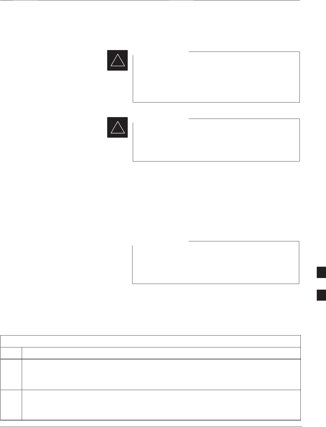
Test Equipment and LMF Connection – continued
DEC 2000 7-9
SCt300 BTS Hardware Installation, ATP and FRU Procedures
PRELIMINARY
Equipment warm-up
Warm-up BTS equipment site for a minimum of 60
minutes prior to the BTS ATP. This assures BTS site
stability and contributes to test accuracy.
(Time spent running initial power–up, hardware/firmware
audit, and BTS download counts as warm–up time).
IMPORTANT
*
Warm-up test equipment for a minimum of 60 minutes
prior to their use in the BTS ATP. This assures maximum
equipment measurement accuracy and consistency during
testing.
IMPORTANT
*
Connecting Test Equipment to
the BTS and LMF
All test equipment is controlled by the LMF via a Serial Cable/GPIB
bus. The LMF expects each piece of test equipment to have a factory-set
GPIB address. If there is a communications problem between the LMF
and any piece of test equipment, you should verify that the GPIB
addresses have been set correctly.
In the following procedure and illustrations, typical DIP
switch positions and/or configurations are shown. If
required, refer to the test equipment OEM user manuals for
additional information.
NOTE
Connecting Advantest R3465 to
BTS
Follow the procedure in Table 7-3 to connect the Advantest R3465 to the
BTS. Refer to Figure 7-9.
Table 7-3: Interfacing test equipment to the BTS
Step Action
1Connect an SMA/BNC coax cable between the following points:
– BNC on the Advantest CDMA TIMEBASE IN port.
– SMA on the 19 MHz port on the diagnostic access area of the BTS.
2Connect an SMA/BNC cable between the following points:
– BNC to one end of the BNC “T.”
– SMA on the 2 Sec port on the diagnostic access area of the BTS.
7

Test Equipment and LMF Connection – continued
PRELIMINARY
SCt300 BTS Hardware Installation, ATP and FRU Procedures DEC 2000
7-10
Table 7-3: Interfacing test equipment to the BTS
Step Action
3Connect a BNC/BNC cable between the following points:
– BNC to one end of the BNC “T.”
– BNC to the EXT TRIG port on the rear panel of the Advantest R3465.
4Connect the BNC “T” to the EVEN SEC/SYNC IN port of the Advantest R356IL.
5Verify the R3561 and R3465 rear panel connections are in place (These are common connections and
should already be installed):
– Serial cable between 3465A rear panel SERIAL I/O port and R3561 SERIAL I/O port.
– SMA cable between 3465A rear panel 1ST LO OUT port and R3561 LOCAL IN port.
7
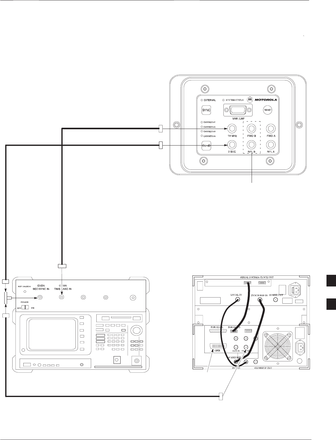
Test Equipment and LMF Connection – continued
DEC 2000 7-11
SCt300 BTS Hardware Installation, ATP and FRU Procedures
PRELIMINARY
Advantest R3465
front panel Advantest R3465
rear panel
BNC
“T”
CONNECTIONS DEPICTED BY HEAVY BOLD LINES ARE
STATIONARY AND SHOULD REMAIN INSTALLED DURING
TEST EQUIPMENT TRANSPORT FROM SITE TO SITE.
19.6608 MHZ REFERENCE
2 SECOND REFERENCE
GPIB
CONNECTOR
FROM EVEN
SEC/SYNC IN
Figure 7-9: R3465 Communications Test Set Timing Signal Detail (Advantest R3465)
THE FWD B AND RFL B
CONNECTORS ARE
NOT PRESENT ON THE
PICOCELL
BTS DIAGNOSTIC ACCESS
AREA (MICROCELL SHOWN)
7
Test Equipment and LMF Connection – continued
PRELIMINARY
SCt300 BTS Hardware Installation, ATP and FRU Procedures DEC 2000
7-12
CONNECTIONS DEPICTED BY DOTTED LINES ARE
STATIONARY AND SHOULD REMAIN INSTALLED DURING
TEST EQUIPMENT TRANSPORT FROM SITE TO SITE.
19.6608 MHZ REFERENCE
2 SECOND REFERENCE
Figure 7-10: Communications Test Set Timing Signal Detail (CyberTest, HP 8935, HP 8921)
THE FWD B AND RFL B
CONNECTORS ARE
NOT PRESENT ON THE
PICOCELL
BTS DIAGNOSTIC ACCESS
AREA (MICROCELL SHOWN)
MOTOROLA CYBERTEST
HP 8935
HP 8921
COMMUNICATIONS TEST SET
SYNC MONITOR
EVEN SEC TICK
PULSE REFERENCE
FROM CSM BOARD
FREQ MONITOR
19.6608 MHZ CLOCK
REFERENCE FROM
CSM BOARD
FREQ MONITOR 19.6608 MHZ CLOCK
REFERENCE FROM CSM BOARD
SYNC MONITOR
EVEN SEC TICK
PULSE REFERENCE
FROM CSM BOARD
FREQ MONITOR 19.6608 MHZ CLOCK
REFERENCE FROM CSM BOARD
SYNC MONITOR
EVEN SEC TICK
PULSE REFERENCE
FROM CSM BOARD
7
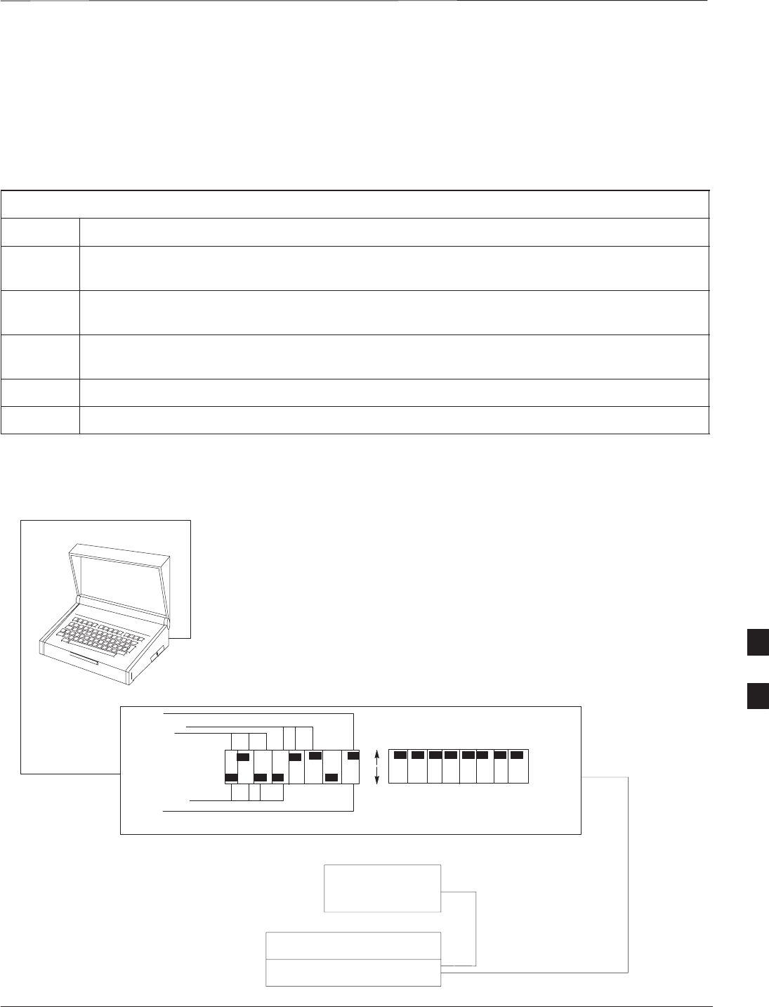
Test Equipment and LMF Connection – continued
DEC 2000 7-13
SCt300 BTS Hardware Installation, ATP and FRU Procedures
PRELIMINARY
Connecting the
Communication Test Set and
Power Meter to the LMF
Use the following procedure in Table 7-4 to connect the communication
test set to the power meter and to the LMF. Refer to Figure 7-11.
Table 7-4: Connect the Communication Test Set and Power Meter to the LMF
Step Action
1Connect the RS232–IEEE488 converter serial cable between the COM1 port of the LMF and the
RS232 port of the RS232–IEEE488 converter.
2Connect a GPIB cable between the RS232–IEEE488 converter and the GPIB port on the
communication test set.
3Connect a GPIB cable between the GPIB port on the communication test set and the GPIB port of
the power meter.
4Set the DIP switches on the RS232–IEEE488 converter as shown in Figure 7-11.
5Power on the communication test set, power meter and RS232–IEEE488 converter.
Figure 7-11: LMF to Test Equipment Connection
LMF
OFF
ON
S MODE
DATA FORMAT
BAUD RATE
GPIB ADDRESS
G MODE
RS232–IEEE488 CONVERTER
POWER METER
ADVANTEST R356IL
ADVANTEST R3645
GPIB CABLE(S) TO GPIB
CONNECTOR ON TEST
EQUIPMENT
RS–232 CABLE
TO COMM1 PORT ON CDMA
LMF NOTEBOOK
7

Test Equipment and LMF Connection – continued
PRELIMINARY
SCt300 BTS Hardware Installation, ATP and FRU Procedures DEC 2000
7-14
Cable Configuration
Figure 7-12 shows the cable configuration for the RS232–IEEE488
converter serial cable.
9–pin D (female) 9–pin D (female)
GND 5 5 GND
RX 3
3 RXTX 2
2 TX
RTS 7 7 RTS
RSD/DCD 1 1 RSD/DCD
DTR 4 4 DTR
DSR 6 6 DSR
Figure 7-12: RS232–IEEE488 Converter Serial Cable Configuration
CTS 8 8 CTS
ON BOTH CONNECTORS SHORT
PINS 7 AND 8;
SHORT PINS 1, 4 AND 6
7

BTS Configuration
DEC 2000 7-15
SCt300 BTS Hardware Installation, ATP and FRU Procedures
PRELIMINARY
Objective
The objective of this procedure is to configure the BTS and establish
communication sessions between the LMF and BTS. This procedure
consists of:
1. Creating a named hyperterminal connection for MMI
communication
2. Establishing an MMI communication session
3. Programming customer operating channel
4. Verifying BTS synchronization mode
5. Verifying DPLL tracking
Creating a Named
HyperTerminal Connection for
MMI Communication
Confirming or changing the configuration data of certain BTS Field
Replaceable Units (FRU) requires establishing an MMI communication
session between the CDMA LMF computer and the FRU. Using features
of the Windows operating system, the connection properties for an MMI
session can be saved on the CDMA LMF computer as a named Windows
HyperTerminal connection. This eliminates the need for setting up
connection parameters each time an MMI session is required to support
optimization.
Once the named connection is saved, a shortcut for it can be created on
the Windows desktop. Double–clicking the shortcut icon will start the
connection without the need to negotiate multiple menu levels.
Follow the procedures in Table 7-5 to establish a named HyperTerminal
connection and create a Windows desktop shortcut for it.
Table 7-5: Create a HyperTerminal Connection
Step Action
1From the Windows Start menu, select:
Programs > Accessories
2 Select Communications, double click the Hyperterminal folder, and then double click on the
Hypertrm.exe icon in the window which opens.
NOTE
SIf a Location Information Window appears, enter the required information, then click on the
Close button. (This is required the first time, even if a modem is not to be used.)
SIf a You need to install a modem..... message appears, click on NO.
3When the Connection Description box opens:
– Type a name for the connection being defined (e.g., MMI Session) in the Name: window,
– Highlight any icon preferred for the named connection in the Icon: chooser window, and
– Click OK.
. . . continued on next page
7

BTS Configuration – continued
PRELIMINARY
SCt300 BTS Hardware Installation, ATP and FRU Procedures DEC 2000
7-16
Table 7-5: Create a HyperTerminal Connection
Step Action
NOTE
For CDMA LMF computer configurations where COM1 is used by another interface such as test
equipment and a physical port is available for COM2, select COM2 in the following step to prevent
conflicts.
4From the Connect using: pick list in the Connect To box displayed, select Direct to Com 1 or
Direct to Com 2 for the RS–232 connection port, and click OK.
5In the Port Settings tab of the COM# Properties window displayed, configure the RS–232 port
settings as follows:
SBits per second: 9600
SData bits: 8
SParity: None
SStop bits: 1
SFlow control: None
6 Click OK.
7Save the defined connection by selecting:
File > Save
8Close the HyperTerminal window by selecting:
File > Exit
9Click the Yes button to disconnect when prompted.
10 If the Hyperterminal folder window is still open, proceed to step 12.
11 Select Communications and double click the Hyperterminal folder.
12 Highlight the newly–created connection icon by clicking on it.
13 Right click and drag the highlighted connection icon to the Windows desktop and release the right
mouse button.
14 From the popup menu which appears, select Create Shortcut(s) Here.
15 If desired, reposition the shortcut icon for the new connection by dragging it to another location on the
Windows desktop.
16 Close the Hyperterminal folder window by selecting:
File > Close
7

BTS Configuration – continued
DEC 2000 7-17
SCt300 BTS Hardware Installation, ATP and FRU Procedures
PRELIMINARY
Establishing an MMI
Communication Session
For those procedures which require MMI communication between the
CDMA LMF and the BTS, follow the procedures in Table 7-6 to initiate
the communication session.
If an LMF session is in progress, logout of the LMF prior
to establishing an MMI communication session. Refer to
steps 1 and 2 of the “Remove LMF” procedure in
Table 7-38.
NOTE
Table 7-6: Establishing MMI Communication
Step Action
1Connect the CDMA LMF computer to the BTS. Refer to the “Connecting the LMF to the BTS”
procedure in this chapter.
2Start the named HyperTerminal connection for MMI sessions by double clicking on its Windows
desktop shortcut.
3NOTE
If a Windows desktop shortcut was not created for the MMI connection, access the connection from
the Windows Start menu by selecting:
Programs > Accessories > Hyperterminal > HyperTerminal >
<Named HyperTerminal
Connection (e g MMI Session)>
C
onnec
ti
on
(
e.g.,
MMI
S
ess
i
on
)
>
Once the connection window opens, establish MMI communication with the BTS FRU by pressing
the CDMA LMF computer Enter key until the prompt identified in the applicable procedure is
obtained.
Every command is entered at the SC300> prompt unless otherwise specified.
Simulated LMF session
You must start a simulated LMF session when you enter MMI
commands. Enter the following command at the MMI prompt to
simulate an LMF link:
sndtype 0xa178
You should enter this command at the beginning of every MMI
Communication Session.
Programming Customer
Operating Channel
A non–volatile database containing the default channel and default
power level of the site must be programmed. The default channel is the
customer operating channel for this site. The default power level must
be set to –50 dBm which will be overwritten by the MM/OMCR when
the site comes on–line.
7

BTS Configuration – continued
PRELIMINARY
SCt300 BTS Hardware Installation, ATP and FRU Procedures DEC 2000
7-18
It is imperative that the customer frequency be programmed into this
database. Failure to do so may result in the RF interference to other
RF–emitting devices in the local area whenever the site is powered up.
Table 7-7: Updating Default Channel Setting to Customer Operating Channel
Step Action
1Connect the LMF computer terminal to the MMI/LMF connector. Refer to Figure 7-7.
2If you have not already done so, logout of the BTS and exit the LMF. Wait 10 seconds before
proceeding.
3Establish an MMI connection session with the BTS. Refer to Table 7-6.
4Simulate an LMF connection by issuing the sndtype 0xa178 command.
5Verify that the BTS is in OOS_RAM status by issuing the status command.
6Enter the op_param –w –50 chan# command.
–w instructs the BTS to write the values into non–volatile memory.
–50 defaults the power to –50dBm
chan# the customer operating channel (76–724)
If the command is successful, the following response will display:
PASSED: TRX EEPROM updated for power level = –50 (dBm) and channel =
chan#
7If no additional MMI sessions are required at this time, exit the MMI session and HyperTerminal
connection by selecting File>Exit.
If you are continuing the MMI session, proceed to Table 7-8.
Synchronization Background
GPS
GPS is typically used as the primary timing reference for CDMA BTSs.
In applications where RGPS is used, the BTS is said to be synchronous
with CDMA system time. The RGPS provides a 1 Pulse Per Second
timing reference and Time Of Day information to allow the BTS to
synchronize to CDMA system time.
HSO
A High Stability Oscillator (HSO) within the BTS provides a backup
timing reference in the event of a GPS outage. Using only the HSO, the
BTS can maintain CDMA system time for up to 24 hours. The BTS can
also use the HSO as the primary timing reference (non–synchronous
operation). However, synchronization to CDMA system time is not
possible. The HSO provides a 1 Pulse Per Second timing reference to
allow the BTS to remain synchronized to CDMA system time in the
event of a GPS outage (synchronous operation) or to provide a stable
frequency reference (non–synchronous operation).
7

BTS Configuration – continued
DEC 2000 7-19
SCt300 BTS Hardware Installation, ATP and FRU Procedures
PRELIMINARY
The HSO must be installed with GPS tracking for at least
24 hours before the HSO can provide 24 hours of backup
for CDMA system time synchronization.
NOTE
BTS
The BTS uses a Digital Phase Locked Loop (DPLL) to track the RGPS
and/or HSO and generate a 19.6608 MHz CDMA timing reference. This
timing reference, in conjunction with Time Of Day information provided
by the RGPS, allows the BTS to synchronize to CDMA system time. A
2 Second reference is also generated by the BTS to allow alignment of
Pilot offsets for the BTS and external test equipment. Both the 19.6608
MHz (19 MHz) and 2 Second (2 Sec) references are available via SMA
connectors located in the Diagnostic Access Area.
In order for the DPLL to begin the RGPS tracking process, the RGPS
must be tracking GPS satellites. In order for the DPLL to begin the
HSO tracking process, the BTS must be powered up (warmed) for at
least 15 minutes.
The DPLL status is defined as being in one of five states: Init, Warm,
A1, A2 and TK.
SThe Init state is the starting state of the DPLL.
SThe Warm state is the condition during the 15 minute BTS warm up
time.
SThe A1 and A2 states are acquisition states when the DPLL is
adjusting the 19.6608 MHz frequency based on the available reference
sources (RGPS or HSO). Under normal operating conditions, the
acquisition states last about 5 minutes.
SThe TK state is the DPLL tracking state and is entered at the end of
the acquisition states. The TK state is required for performing ATP.
Synchronization Configuration
The Sync button in the Diagnostic Access Area is used to toggle the
RGPS or HSO as the primary timing reference for the BTS. If the
External indicator in the Diagnostic Access Area is illuminated, the BTS
expects an RGPS to be present for use as the primary timing reference.
If the External indicator is not illuminated, the BTS will use the internal
HSO as the primary timing reference.
Use the procedure in Table 7-8 to verify and, if necessary change the
BTS Sync mode.
7

BTS Configuration – continued
PRELIMINARY
SCt300 BTS Hardware Installation, ATP and FRU Procedures DEC 2000
7-20
Table 7-8: Verify BTS Sync Mode
Step Action
1If an MMI session was established, proceed to step 6. If no MMI session is running, proceed to
step 2.
2Connect the MMI/LMF.
3Open an MMI Communication session.
4Simulate an LMF connection by issuing the sndtype 0xa178 command.
5Verify that the BTS is in OOS_RAM status by issuing the status command.
6Observe the condition of the External indicator.
7No further action is required if the BTS is in the desired Sync mode. Continue with Step 8 if the
Sync mode needs to be altered.
8Push the Sync button to change the BTS Sync mode.
9Reset the BTS using the Reset button in the Diagnostic Access Area.
10 If no additional MMI sessions are required at this time, exit the MMI session and HyperTerminal
connection by selecting File>Exit.
If you are continuing the MMI session, proceed to Table 7-9.
Synchronization Verification
The DPLL within the BTS must be tracking either RGPS or HSO in
order to perform ATP. Use the procedure in Table 7-9 to verify DPLL
tracking.
Table 7-9: Verify DPLL Tracking
Step Action
1If an MMI session was established, proceed to step 6. If no MMI session is running, proceed to
step 2.
2Connect the MMI/LMF.
3Open an MMI Communication session.
4Simulate an LMF connection by issuing the sndtype 0xa178 command.
5Verify that the BTS is in OOS_RAM status by issuing the status command.
6If an RGPS is not present, go to Step 9.
. . . continued on next page
7

BTS Configuration – continued
DEC 2000 7-21
SCt300 BTS Hardware Installation, ATP and FRU Procedures
PRELIMINARY
Table 7-9: Verify DPLL Tracking
Step Action
7Enter the gps_status command to display the current state of the RGPS. Observe the following
typical response:
gps_status
GPS Receiver Identification:
Current GPS Time :8 03 1999 23:01:12
Current GPS Receiver Status :8
Number of Satellites Currently visible :11
Number of Satellites Currently received :5
Number of Satellites Currently tracked :5
GPS Receiver Type :UT
Current GPS Task State :GPS_TRACK
Current Dilution of Precision (HDOP (2D)/antenna ok [0x01]): 0
Chan: 0, SVID: 9, Mode: 8, RSSI: 44, Status: 0xaa
Chan: 1, SVID: 4, Mode: 8, RSSI: 46, Status: 0xaa
Chan: 2, SVID: 10, Mode: 8, RSSI: 44, Status: 0xaa
Chan: 3, SVID: 6, Mode: 8, RSSI: 41, Status: 0xaa
Chan: 4, SVID: 7, Mode: 8, RSSI: 43, Status: 0xaa
Chan: 5, SVID: 24, Mode: 8, RSSI: 47, Status: 0xaa
Chan: 6, SVID: 30, Mode: 8, RSSI: 45, Status: 0xaa
Chan: 7, SVID: 5, Mode: 8, RSSI: 48, Status: 0xaa
Current Longitude: –350250952
Current Latitude: 118244730
Current Height: 24019
8The RGPS must have a Current GPS Task State of GPS_TRACK to proceed.
NOTE
NOTE
GPS tracking times vary depending on location and installation.
9Issue the dpll_status command to display the current state of the DPLL. Observe the following
typical response:
Current source set to: GPS reference
DPLL control task state: DPLL track.
DPLL status (not valid if using even sec src):
c:0000 off: –8639450,6736579,7204904 TK
(Note: This must say TK. A1 and A2 states will have preceded it)
Mode cntr: 120
ip: 9, iq: 4
aip1: 9, aiq1: 4
aip2: 6, aiq2: –2
tip: 3, tiq: –9
integrator: 4096
. . . continued on next page
7

BTS Configuration – continued
PRELIMINARY
SCt300 BTS Hardware Installation, ATP and FRU Procedures DEC 2000
7-22
Table 7-9: Verify DPLL Tracking
Step Action
10 Verify that the DPLL is “tracking” either the RGPS or HSO. The DPLL must have a Current
source set to of GPS reference or HSO reference. The DPLL must also have a
DPLL control task state of DPLL track.
11 If no additional MMI sessions are required at this time, exit the MMI session and HyperTerminal
connection by selecting File>Exit.
If you are continuing the MMI session, proceed to Table 7-10.
Location Coordinates
The BTS supplies the RGPS with default startup coordinates (latitude
and longitude) in order to assist the RGPS in tracking satellites. The
default startup coordinates can be modified and saved into non–volatile
memory to speed the tracking of satellites.
Use the procedure in Table 7-10 to verify and, if necessary, modify the
default startup coordinates. The procedure in Table 7-10 is only
applicable to sites equipped with an RGPS.
Table 7-10: Verify Default Startup Coordinates
Step Action
1If an MMI session was established, proceed to step 6. If no MMI session is running, proceed to
step 2.
2Connect the LMF/MMI.
3Open an MMI Communication session.
4Simulate an LMF connection by issuing the sndtype 0xa178 command.
5Verify that the BTS is in OOS_RAM status by issuing the status command.
6Issue the dpll_status command to display the current state of the DPLL. Verify that the DPLL
has a ”Current source set to” of GPS reference and a ”DPLL control task state” of DPLL
track. The DPLL must be tracking GPS in order to complete this procedure.
7* IMPORTANT
The values for longitude and latitude in response to the gps_status command are given in units
of milli arcseconds Be careful to record the values accurately including any leading negative ( )
o
f
m
illi
–arcsecon
d
s.
B
e care
f
u
l
to recor
d
t
h
e va
l
ues accurate
l
y
i
nc
l
u
di
ng any
l
ea
di
ng negat
i
ve
(
–
)
signs. The value of Current Height is given in units of centimeters.
Enter the gps_status command.
8Record the values displayed for Current Longitude, Current Latitude and
Current Height.
. . . continued on next page
7

BTS Configuration – continued
DEC 2000 7-23
SCt300 BTS Hardware Installation, ATP and FRU Procedures
PRELIMINARY
Table 7-10: Verify Default Startup Coordinates
Step Action
9* IMPORTANT
The gps_config command displays the default startup coordinates for the BTS. Note that
latitude is displayed first, followed by longitude. This is in reverse order compared to
the response of the gps_status command. The values for latitude and longitude are given in
units of milli–arcseconds. The value of Current Height is given in units of centimeters.
Enter the gps_config command to display the default startup coordinates for the BTS. Observe
the following typical response:
GPS Configuration data:
latitude: 151679715 msec
longitude: –316791269 msec
height: 19740 centi
–
meters
height
:
19740
centi
–
meters
height_type: 0
cable_delay: 0 nsec
accuracy: 0
If the default startup coordinates need to be modified, the gps_config command can be issued
with additional parameters. Using the Current Longitude, Current Latitude and
Current Height values recorded in step 8, issue the following command:
gps_config <latitude> <longitude> <height> 0 0 0
Be careful to input the latitude and longitude in the proper order along with any leading negative
(–) signs.
The GPS Height Type Configuration should be set to “0.”
10 Issue the gps_config to verify that the coordinates are set.
11 Reset the BTS to save the new coordinates.
12 Repeat the steps in Table 7-9 to verify the DPLL status prior to performing ATP.
13 If no additional MMI sessions are required at this time, exit the MMI session and HyperTerminal
connection by selecting File>Exit.7

BTS Software
PRELIMINARY
SCt300 BTS Hardware Installation, ATP and FRU Procedures DEC 2000
7-24
Objective
This objective of this procedure is to:
1. Install the LMF program.
2. Create a site specific BTS directory.
3. Start the LMF.
4. Login to the BTS
5. Update the BTS–specific CDF file.
6. Download and enable the MAWI
Install the LMF Program and
BTS Binaries
Install the LMF and BTS binaries on the PC to be used if they are not already
installed. Refer to the CDMA LMF Operator’s Guide, 68P64114A78 for
the installation procedure.
Create a Site–Specific BTS
Directory
Follow the steps in Table 7-11 to create a bts–
bts#
directory, to which
the bts–bts#.cdf, cbsc–1.cdf, bts–bts#.cal, and ATP
report files will reside.
Table 7-11: Create Site–Specific BTS Directory
Step Action
1Use MS Windows Explorer to create a bts–# folder under the wlmf\cdma folder
(where # is the bts number).
2Get the bts–#.cdf file and cbsc–#.cdf file from the CBSC and put a copy of
the files in the wlmf\cdma\bts–# folder. Refer to the LMF help screens or the
CDMA LMF Operator’s Guide, 68P64114A21 for the copy file procedure.
Start the LMF and Login to the
BTS
Use the following procedure in Table 7-12 to start the LMF and login to
the BTS.
Prerequisites
1. A bts–# folder with a correct CDF and CBSC file exists.
2. The LMF notebook is correctly set up and connected to the BTS.
Refer to Figure 7-7.
7

BTS Software – continued
DEC 2000 7-25
SCt300 BTS Hardware Installation, ATP and FRU Procedures
PRELIMINARY
Procedure
The Refresh button can be used to update the Available
Base Stations pick list to include any new bts–#
folders added/created after the LMF was started. To logout
of the BTS, click on Select>Logout. A confirm logout
pop–up message will appear.
NOTE
Table 7-12: Start the LMF and Login to the BTS
Step Action
1Click on the LMF desktop icon. The LMF window should appear.
2Click on the Login tab if it is not already displayed.
3Double–click on CDMA in the Available Base Stations pick list if the list of
available BTSs is not displayed.
4Click on the desired BTS.
5Is all of the information in the Serial Login tab and Equipage Information box
list correct?
– If YES, go to step 8.
– If NO, go to step 6.
6Click on the Serial Login tab if it is not in the forefront. Select the correct Com
Port (normally COM2) and select the desired Baud Rate (normally 9600 for tests
and 38400 for downloads).
7If applicable, change the Multi–Channel Preselector selection (normally MPC).
8Click on the Login button. A BTS tab with the BTS should be displayed.
NOTE
A SC6XX BTS picture will appear instead of a SC300 picture.
Update BTS Specific CDF File
Device Load Version
Follow the steps in Table 7-13 to update the existing BTS specific CDF
file NextLoad parameter to reflect the current device load version to be
downloaded.
The NextLoad version parameter in the CDF file for a BTS can be
updated to one of the existing version numbers in the
wlmf>cdma>loads folder. When code is downloaded the code file
used is determined by the NextLoad parameter in the CDF file. If a
version number folder that has the same number as the NextLoad
parameter is not found when the download code function is used the
LMF will not automatically select the code and data files to be
downloaded.
7

BTS Software – continued
PRELIMINARY
SCt300 BTS Hardware Installation, ATP and FRU Procedures DEC 2000
7-26
Device load version in the CDF file does not have to match
the current version loaded at the OMCR/CBSC.
NOTE
Table 7-13: Update BTS Specific CDF File Device Load Version
Step Action
1Click on the Util menu.
2Select the Tools menu item.
3Click on the Update NextLoad device.
4Select the desired version number (button next to desired version number must be darkened).
5Click on the Save button. A pop–up message will appear indicating that the CDF file has been
updated.
NOTE
NOTE
At this point, a backup copy of the original CDF is created with a _bak extension, (e.g.,
bts–812.cdf_bak ).
6Click on the OK button to dismiss the pop–up message.
Download/Enable MAWI
The objective of this procedure is to download and enable the BTS.
The BTS software platform is based on the Motorola Advanced
Wideband Interface (MAWI). The term MAWI is used to refer to the
Microcell or Picocell from the LMF’s point of view.
The BTS is shipped from the factory with all the software
downloaded. Use the load procedure only when new
software is loaded.
NOTE
Follow the steps outlined in Table 7-14 to download the code and data to
enable the MAWI.
Before the download/enable process, use the status function and verify
the MAWI responds with status information. Use this information to get
the current code loaded in MAWI.
7

BTS Software – continued
DEC 2000 7-27
SCt300 BTS Hardware Installation, ATP and FRU Procedures
PRELIMINARY
Table 7-14: Download/Enable MAWI
Step Action
1If the ATP is going to be run, the MAWI has to have the same code load as the LMF CDF or the site
specific information cannot be loaded to MAWI (PN offset, etc.) for ATP to complete.
2If downloading code, insure the LMF is logged into the BTS at 38400 Baud Rate for timely
download (20 minutes vs 2+ hours).
3Click on the MAWI and select Device>Download Code.
A status report is displayed that confirms the change in device status. Click OK to close status
window.
4Click on the MAWI and select Device>Download Data. A status report is displayed that
confirms the change in device status. Click OK to close status window.
5Click on the MAWI and select Device>Enable to enable the MAWI. The MAWI changes to green
(INS–ACT test mode).
Cell Site Data File (CDF)
The Configuration Data File (CDF) includes the CDMA channel element
allocation plan. This plan indicates how each CDMA carrier is
configured, and how the paging, sync, traffic, and access channel
elements (and associated gain values) are assigned.
The CDF file also contains a table for the Effective Rated Power (ERP)
for each transmit antenna. Motorola System Engineering specifies the
ERP of a transmit antenna based on site geography, antenna placement,
and government regulations. Working from this ERP requirement, the
antenna gain, (dependent on the units of measurement specified) and
antenna feed line loss can be combined to determine the required power
at the BTS TX output.
Refer to the CDMA LMF Operators Guide; 68P64114A78
for additional information on the layout of the LMF
directory structure (including cdf file locations and
formats).
NOTE
Site equipage verification
If you have not already done so, use an editor to view the CDF, and
review the site documentation. Verify the site engineering equipage data
in the CDF to the actual site hardware.
If the current LMF or BTS binaries need to be installed on
the LMF PC, or for more information on viewing CDF
files, refer to the CDMA LMF Operators Guide;
68P64114A78.
NOTE
7

BTS Software – continued
PRELIMINARY
SCt300 BTS Hardware Installation, ATP and FRU Procedures DEC 2000
7-28
System status LED states
Table 7-15 lists all of the possible system status LED states.
Table 7-15: System Status LED States
System Status LED Status Indication
Steady Green INS_ACT# or INS_SBY$, no alarms
Slow Flashing Red/Green
(0.2s Red, 1.4s Green) INS_ACT or INS_SBY w/alarms(s)
Fast Flashing Green/Off
(0.2s Green, 0.2s Off) OOS_RAM! with no alarms
Fast Flashing Red/Green
(0.2s Red, 0.2s Green) OOS_RAM with alarms(s)
Slow Flashing Green/Off
(0.2s Green, 1.4s Off) OOS_ROM@ with no alarms
Slow Flashing Green/Red
(0.2s Green, 1.4s Red) OOS_ROM with alarm(s)
Steady Red Critical hardware failure
Fast Flashing Red/Off
(0.25s Red/0.25s Off)%
NOTE
The MAWI has powered up in boot code because
the ROM code is either corrupt or not present.
This condition may indicate a MAWI hardware
failure.
#1: RAM test failure
#2: FLASH 1 (512K) manufacture/device ID mismatch
#3: FLASH 2 (512K) manufacture/device ID mismatch
#4: FLASH 3 (512K) manufacture/device ID mismatch
#5: Modem present but untrained
#6: Unknown interrupt event
#7: Reset by hardware watchdog timeout
#8: Reset by software watchdog timeout
#9: Reset by double bus fault
#10: Reset by loss of clock
#11: Reset by RESET instruction
#12: Reset by soft reset pin
Off No DC Power applied to module
!OOS_RAM refers to a MAWI that is loaded but not enabled
@OOS_ROM refers to a MAWI that is not loaded.
#INS_ACT refers to a MAWI that is in service and active.
$INS_SBY refers to a MAWI that is in service but on standby.
%The number of flashes equals the alarm #, with a three–second pause between flashes.
7
Test Equipment Setup
DEC 2000 7-29
SCt300 BTS Hardware Installation, ATP and FRU Procedures
PRELIMINARY
Purpose
The following test equipment setup applies to the BTS Acceptance Test
Procedure (ATP).
Required Test Equipment
The following pieces of test equipment will be required to perform these
ATP tests:
SLMF
SPower Meter
SCommunications Test Set
To prevent damage to the test equipment, all Microcell
transmit (TX) tests must be made using the 30 dB
attenuator.
CAUTION
Test Set Calibration
Background
Proper test equipment calibration ensures that the test equipment and
associated test cables do not introduce measurement errors, and that
measurements are correct.
If the test set being used to interface with the BTS has been
calibrated and maintained as a set, this procedure does not
need to be performed. (Test Set includes LMF terminal,
communications test set, additional test equipment,
associated test cables, and adapters.)
NOTE
This procedure must be performed prior to beginning the optimization.
Verify all test equipment (including all associated test cables and
adapters actually used to interface all test equipment and the BTS) has
been calibrated and maintained as a set.
If any piece of test equipment, test cable, or RF adapter,
that makes up the calibrated test equipment set, has been
replaced, re-calibration must be performed. Failure to do so
can introduce measurement errors, resulting in incorrect
measurements and degradation to system performance.
CAUTION
7

Test Equipment Setup – continued
PRELIMINARY
SCt300 BTS Hardware Installation, ATP and FRU Procedures DEC 2000
7-30
Calibration of the communications test set (or equivalent
test equipment) must be performed at the site before
calibrating the overall test set. Calibrate the test equipment
after it has been allowed to warm–up and stabilize for a
minimum of 60 minutes.
IMPORTANT
*
Purpose of Test set
Calibration
These procedures access the LMF automated calibration routine used to
determine the path losses of the supported communications analyzer,
power meter, associated test cables, and (if used) antenna switch that
make up the overall calibrated test set. After calibration, the gain/loss
offset values are stored in a test measurement offset file on the LMF.
Selecting Test Equipment
Use LMF Options from the Options menu list to select test equipment
automatically (using the autodetect feature) or manually.
A Serial Connection and a Network Connection tab are provided for
test equipment selection. The Serial Connection tab is used when the
test equipment items are connected directly to the LMF computer via a
GPIB box (normal setup). The Network Connection tab is used when
the test equipment is to be connected remotely via a network connection.
Prerequisites
Ensure the following prerequisites have been met before proceeding:
STest equipment is correctly connected and turned on.
SCDMA LMF computer serial port and test equipment are connected to
the GPIB box.
Manually Selecting Test
Equipment in a Serial
Connection Tab
Test equipment can be manually specified before, or after, the test
equipment is connected. The LMF does not check to see if the test
equipment is actually detected for manual specification. Follow the
procedure in Table 7-16 to select test equipment manually.
Table 7-16: Selecting Test Equipment Manually in a Serial Connection Tab
nStep Action
1From the Options menu, select LMF Options.
The LMF Options window appears.
2Click on the Serial Connection tab (if not in the forefront).
. . . continued on next page
7

Test Equipment Setup – continued
DEC 2000 7-31
SCt300 BTS Hardware Installation, ATP and FRU Procedures
PRELIMINARY
Table 7-16: Selecting Test Equipment Manually in a Serial Connection Tab
nActionStep
3Select the correct serial port in the COMM Port pick list (normally COM1).
4Click on the Manual Specification button (if not enabled).
5Click on the check box corresponding to the test item(s) to be used.
6Type the GPIB address in the corresponding GPIB address box.
Recommended Addresses
13=Power Meter
18=CDMA Analyzer
7Click on Apply. (The button darkens until the selection has been committed.)
NOTE
With manual selection, the LMF does not detect the test equipment to see if it is connected and
communicating with the LMF.
8Click on Dismiss to close the test equipment window.
Automatically Selecting Test
Equipment in a Serial
Connection Tab When using the auto-detection feature to select test equipment, the LMF
examines which test equipment items are actually communicating with
the LMF. Follow the procedure in Table 7-17 to use the auto-detect
feature.
Table 7-17: Selecting Test Equipment Using Auto-Detect
nStep Action
1From the Options menu, select LMF Options.
The LMF Options window appears.
2Click on the Serial Connection tab (if not in the forefront).
3Select the correct serial port in the COMM Port pick list (normally COM1).
4Click on Auto–Detection (if not enabled).
5Type in the GPIB addresses in the box labeled GPIB address to search (if not already displayed).
NOTE
When both a power meter and analyzer are selected, the first item listed in the GPIB addresses to
search box is used for RF power measurements (i.e., TX calibration). The address for a power
meter is normally 13 and the address for a CDMA analyzer is normally 18. If 13,18 is included in
the GPIB addresses to search box, the power meter (13) is used for RF power measurements. If
the test equipment items are manually selected the CDMA analyzer is used only if a power meter
is not selected.
. . . continued on next page
7

Test Equipment Setup – continued
PRELIMINARY
SCt300 BTS Hardware Installation, ATP and FRU Procedures DEC 2000
7-32
Table 7-17: Selecting Test Equipment Using Auto-Detect
nActionStep
6Click on Apply.
NOTE
The button darkens until the selection has been committed. A check mark appears in the Manual
Configuration section for detected test equipment items.
7 Click Dismiss to close the LMF Options window.
Calibrating Test Equipment
The calibrate test equipment function zeros the power measurement level
of the test equipment item that is to be used for TX calibration and audit.
If both a power meter and an analyzer are connected, only the power
meter is zeroed.
Use the Calibrate Test Equipment menu item from the Util menu to
calibrate test equipment. The test equipment must be selected before
calibration can begin. Follow the procedure in Table 7-18 to calibrate the
test equipment.
Prerequisites
Ensure the following prerequisites have been met before proceeding:
STest equipment to be calibrated has been connected correctly for tests
that are to be run.
STest equipment has been selected.
Table 7-18: Test Equipment Calibration
nStep Action
1From the Util menu, select Calibrate Test Equipment.
A Directions window is displayed.
2Follow the directions provided.
3Click on Continue to close the Directions window.
A status report window is displayed.
4Click on OK to close the status report window.
7

Test Equipment Setup – continued
DEC 2000 7-33
SCt300 BTS Hardware Installation, ATP and FRU Procedures
PRELIMINARY
R3465 Calibration/GPIB
Address & Clock Setup
Follow the steps in Table 7-20 to configure and calibrate the
communication test set.
Table 7-19: R3465 Calibration Procedure
Step Action
NOTE
The calibration should be performed only after the analyzer has been allowed to warm–up and stabilize
for a minimum of 60 minutes.
1Perform the following to set the standard parameters on the test set:
SPush the SHIFT and PRESET pushbutton (just below the CRT display)
SSelect TRANSIENT
– Select Setup STD in CRT menu.
2Verify and if required set the following parameters in the display (rotate the vernier knob to navigate
the screen, push the vernier knob to select):
SSet Type to Japan (800 MHz)
SSet Link to FORWARD
SVerify Rate to 9600/14400 (set Link to REVERSE if Rate needs to be set)
SSet Offset Level to 0.0 dB
SSet Freq Input to FREQUENCY
SSet Cont. Auto Level Set to OFF
– Select Return in CRT menu.
3Verify that the Communications test set GPIB address and Date/Time are set correctly.
SCommunications test set GPIB address = 18 (perform the following to view/set as required).
SSelect CW
SPush the LCL pushbutton (just below the CRT display)
– Push the GPIB and Others CRT menu key to view the current address.
–If required, change GPIB address to 18
(rotate the vernier knob to set, push the vernier knob to enter)
SVerify the current Date and Time in upper/right of CRT display
(perform the following to set if required).
– Push the Date/Time CRT menu key
–If required, change to correct Date/Time
(rotate the vernier knob to select and set, push the vernier knob to enter)
SSelect CW
7

Test Equipment Setup – continued
PRELIMINARY
SCt300 BTS Hardware Installation, ATP and FRU Procedures DEC 2000
7-34
Table 7-19: R3465 Calibration Procedure
Step Action
4Verify that the CDMA Clock Source References are set correctly:
SPush the ADVANCE key
SPush the CDMA Sig. CRT menu key
SPush the Setup CRT menu key
SPush the Ref Clock CRT menu key
–If required, change SynthRef (MHz) to 10
(rotate the vernier knob to set, push the vernier knob to enter)
–If required, change CDMA–TB Source to 19.6608
(rotate the vern
i
er knob to set push the vern
i
er knob to enter)
(
ro
t
a
t
e
th
e vern er
k
no
b
t
o se
t
, pus
h
th
e vern er
k
no
b
t
o en
t
er
)
SVerify that ON is active in the Output CRT menu key
SVerify that OFF is active in the Mod CRT menu key
SPush the return menu key
SPush the return menu key again
* IMPORTANT
– Test equipment warm–up may vary depending on operating environment or initial temperature of
unit upon turn–on. Consult test equipment OEM documentation for additional information as
required.
5Connect the male BNC to male N cable between the CAL OUT connector and the INPUT 50 W
connector.
6Perform the following to run the internal calibration on the test set:
SSelect CW
SPush the SHIFT and CAL pushbuttons
– Select Cal All in CRT menu.
Internal calibration should complete in about 6 minutes.
7
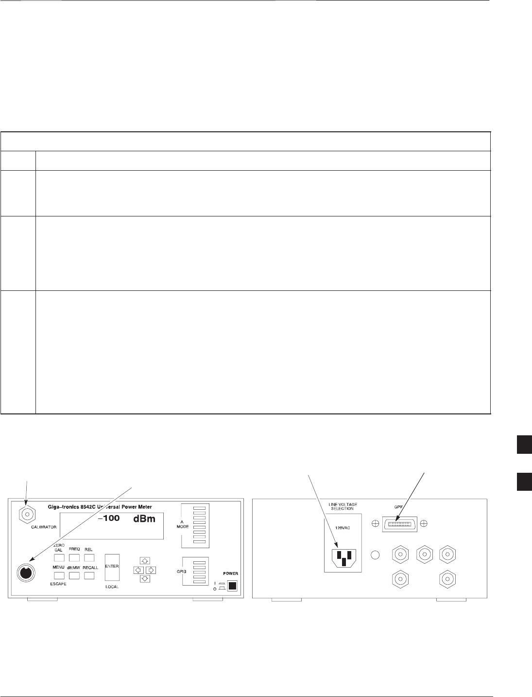
Test Equipment Setup – continued
DEC 2000 7-35
SCt300 BTS Hardware Installation, ATP and FRU Procedures
PRELIMINARY
Power Meter GPIB Setup
Precise transmit output power measurements are made using a
broadband power meter with a sensitive power sensor. Follow the steps
outlined in Table 7-20 to set the GPIB address of the power meter.
Refer to Figure 7-13.
Table 7-20: Gigatronics Power Meter GPIB Address Procedure
Step Action
! CAUTION
Do not connect/disconnect the power meter sensor cable with ac power applied to the meter.
Disconnection could result in destruction of the sensing element or mis–calibration.
1Make sure the power meter POWER pushbutton is OFF. Connect the power sensor cable to the
SENSOR input. Set the POWER pushbutton to ON.
NOTE
N
O
TE
The calibration should be performed only after the power meter and sensor have been allowed to
warm–up and stabilize for a minimum of 60 minutes.
2Verify that the Power Meter GPIB mode and address are set correctly:
SPower Meter (currently used by LMF for calibration)
GPIB address = 13 Consult test equipment OEM documentation for additional info as required).
– Press MENU. Use the b arrow key to select CONFIG MENU and press ENTER.
– Use the b arrow key to select GPIB and press ENTER.
– Use the by arrow keys as required to set MODE to 8541C or 8542C (as appropriate).
– Press ' and use the by arrow keys as required to set ADDRESS to 13.
– Press ENTER.
Figure 7-13: Power Meter Detail
CONNECT POWER SENSOR
WITH POWER METER
TURNED OFF
CONNECT POWER SENSOR TO
CALIBRATOR POWER REFERENCE WHEN
CALIBRATING/ZEROING UNIT
FRONT View REAR View
GPIB CONNECTION
AC POWER 7

Test Equipment Setup – continued
PRELIMINARY
SCt300 BTS Hardware Installation, ATP and FRU Procedures DEC 2000
7-36
Acceptance Test (ATP)
Equipment Setup
Follow the steps outlined in Table 7-21 to set up test equipment prior to
performing ATP tests.
LMF based measurements factor in cable and attenuator
loss between the BTS and test equipment. No additional
attenuation can be inserted as the additional losses would
not be factored in.
IMPORTANT
*
Table 7-21: Test Equipment Setup
Step Action
1If you have not already done so, interface the CDMA LMF computer to the BTS and login to the BTS.
2Refer to NO TAG to set up test equipment.
Verify that the coaxial cable from the appropriate TX connector on the BTS is connected to the test
equipment RF input port via the in line 30 dB high power attenuator for MicroCell BTSs.
7

Test Equipment Selection
DEC 2000 7-37
SCt300 BTS Hardware Installation, ATP and FRU Procedures
PRELIMINARY
Objective
The objective of this procedure is to select the test equipment used for
BTS testing. The LMF must select the test equipment before it is used
for BTS testing.
Prerequisites
The following are prerequisites for test equipment selection:
1. Test equipment to be used has been connected as shown in
Figure 7-11.
2. Power for the test equipment and GPIB box has been turned on.
3. LMF has been started (do not have to be logged in to the BTS).
Procedure
Follow the steps in Table 7-22 for test equipment selection
The test equipment can also be selected via a manual or
automatic connection. Refer to the CDMA LMF
Operator’s Guide, 68P64114A78 for the procedures.
NOTE
Table 7-22: Test Equipment Selection
Step Action
1Click on Options from the menu.
2Click on Options>LMF Options. A LMF Options window appears.
3Select the correct COM port from the ComPort pick list (normally COM1).
4Click on the Auto–Detection button if it is not enabled.
5If the GPIB addresses are not displayed, enter the GPIB addresses in the box labeled GPIB
address to search.
NOTE
When both a power meter and a communication test set are selected the first item listed in the
Wh
en
b
o
th
a power me
t
er an
d
a commun
i
ca
ti
on
t
es
t
se
t
are se
l
ec
t
e
d
,
th
e
fi
rs
t
it
em
li
s
t
e
d
i
n
th
e
GPIB address to search box will be used for RF power measurements (e.g., TX calibration
and audit). The address for a power meter is 13 and the address for a communications test set is
18. The numbers 13 and 18 must be included in the GPIB address to search box so the
power meter (13) will be used for TX calibration and audit.
6Click on the Apply button. The button will darken until the selection has been committed. A
check mark will appear in the Manual Configuration section for detected test equipment items.
7Click on the Dismiss button to close the LMF Options window.
7

Power Meter Calibration
PRELIMINARY
SCt300 BTS Hardware Installation, ATP and FRU Procedures DEC 2000
7-38
Objective
This procedure calibrates the power meter that will be used for cable
calibration and BTS testing.
Prerequisites
The following are prerequisites for power meter calibration:
1. The power meter is connected. Refer to Figure 7-11 in the “Test
Equipment Selection” procedure.
2. Test equipment has been selected.
Procedure
Follow the steps in Table 7-23 to calibrate the power meter.
Table 7-23: Calibrate the Power Meter
Step Action
1Click on Util>Calibrate Test Equipment. A cable connection direction pop–up is displayed.
2Follow the directions provided.
3Click on the OK button to close the status results window.
7
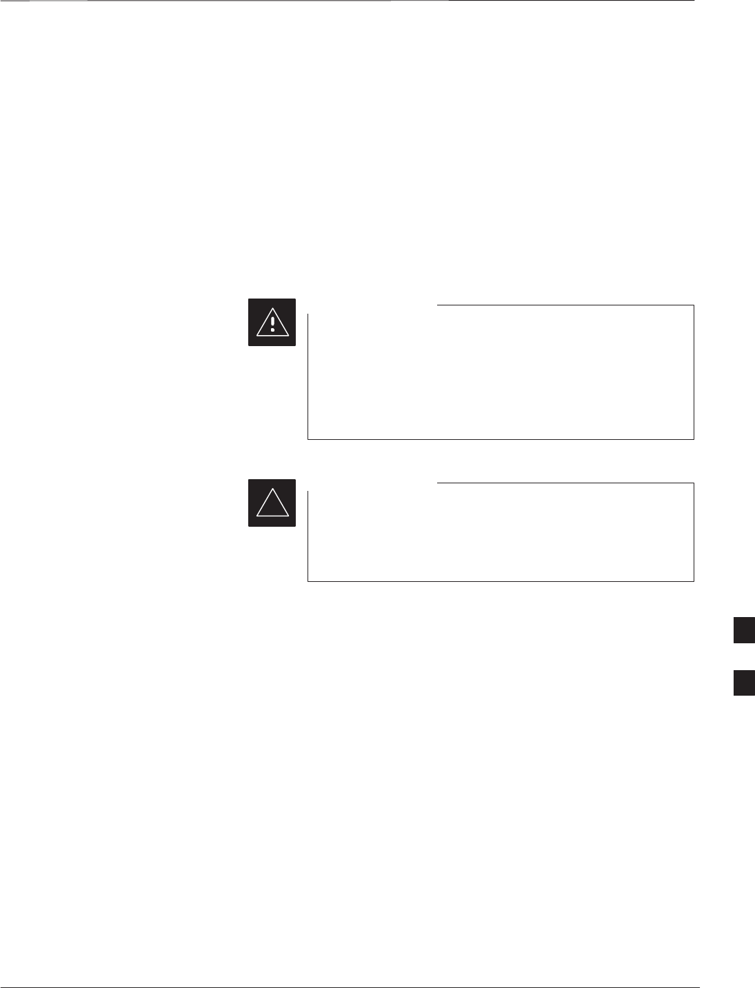
Test Cable Calibration
DEC 2000 7-39
SCt300 BTS Hardware Installation, ATP and FRU Procedures
PRELIMINARY
Background
Proper test equipment setup ensures that all measurements are correct,
and that test equipment and associated test cables do not introduce
measurement errors. Motorola recommends repeating cable calibration
prior to testing at each BTS site.
If not already done so, this procedure needs to be performed prior to
beginning the ATP. Verify that all test equipment (including all
associated test cables and adapters actually used to interface all test
equipment and the BTS together) has been calibrated.
In the event that any piece of test equipment, test cable, or
RF adaptor is replaced that makes up the calibrated test
equipment set, re–calibration should be performed. Failure
to do so can introduce measurement errors, resulting in
incorrect measurements or degradation to system
performance.
CAUTION
Calibration of the communications test set (or equivalent
test equipment) must be performed at the site before
calibrating the overall test set after it has been allowed to
warm–up and stabilize for a minimum of 60 minutes.
IMPORTANT
*
Purpose
This procedure accesses the LMF automated calibration routine used to
determine the path losses of the supported communications analyzer,
power meter, associated test cables, and (if used) RF Network making up
the overall calibrated test set. After calibration, the gain/loss offset
values are stored in a test measurement offset file on the LMF.
If you have obtained the test cable insertion loss values previously, you
can manually enter them using the Util>Edit>CableLoss>TX or RX
menu.
Do not use the manual method if you plan to run/have already run the
cable calibration procedure.
7

Test Cable Calibration – continued
PRELIMINARY
SCt300 BTS Hardware Installation, ATP and FRU Procedures DEC 2000
7-40
Automated Cable Calibration
Procedure
This procedure calibrates the cables that will be used for BTS testing.
Follow the steps in Table 7-24 to calibrate the test cables.
Prerequisites
1. Test equipment has been connected as shown in Figure 7-11.
2. Power for the test equipment and GPIB box has been turned on.
3. LMF has been started and BTS has been logged into.
Procedure
Follow the steps in Table 7-24 to calibrate the test cables. Refer to
Figure 7-14.
A 30 dB attenuator is used for Microcell (high power)
BTSs. A 10 dB attenuator is used for Picocell BTSs.
NOTE
Table 7-24: Automated Cable Calibration
Step Action
1Click on the Util>Cable Calibration menu item.
2Select one of the following options in the Cable
Calibration menu: TX and RX CABLE CAL, TX
CABLE CAL, or RX CABLE CAL.
N
O
TE
NOTE
Normally the option TX and RX CABLE CAL is used so
both the TX and RX cable configurations are calibrated. The
TX CABLE CAL and RX CABLE CAL options are used
only if one of the cable configurations needs to be calibrated.
3Click the OK button. A Directions pop–up is displayed for
each step of the cable calibration.
4Follow the directions displayed for each step. A status report
window is displayed with the results of the cable calibration.
5Click on OK to close the status report window.
7
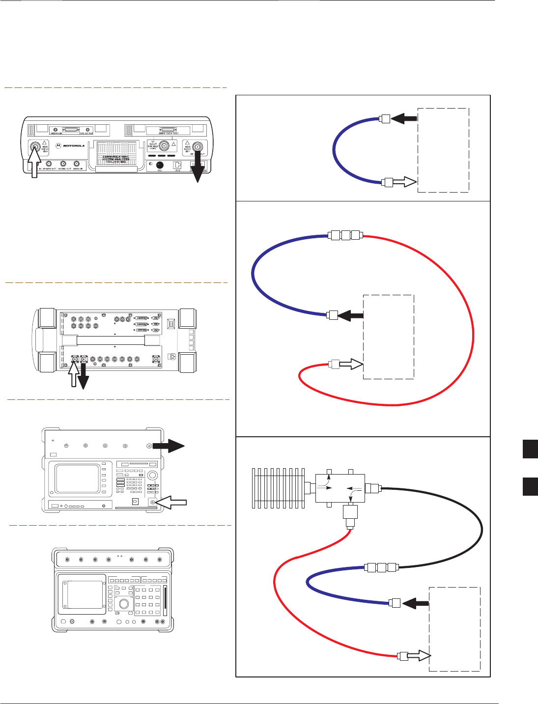
Test Cable Calibration – continued
DEC 2000 7-41
SCt300 BTS Hardware Installation, ATP and FRU Procedures
PRELIMINARY
Figure 7-14: Cable Calibration Test Setup
Motorola CyberTest
Hewlett–Packard Model HP 8935
Advantest Model R3465
DUPLEX
OUT
RF OUT
50–OHM
INPUT
50–OHM
RF GEN OUTANT IN
ANT
IN
SUPPORTED TEST SETS
100–WATT (MIN)
NON–RADIATING
RF LOAD
TEST
SET
A. SHORT CABLE CAL
SHORT
CABLE
B. RX TEST SETUP
TEST
SET
C. TX TEST SETUP
20 DB PAD
FOR 1.9 GHZ
CALIBRATION SET UP
N–N FEMALE
ADAPTER
TX
CABLE
TX
CABLE
SHORT
CABLE
Note: The Directional Coupler is not used with the
Cybertest Test Set. The TX cable is connected
directly to the Cybertest Test Set.
A 10dB attenuator must be used with the short test
cable for cable calibration with the CyberTest Test
Set. The 10dB attenuator is used only for the cable
calibration procedure, not with the test cables for
TX calibration and ATP tests.
TEST
SET
RX
CABLE
SHORT
CABLE
FW00089
Note: For 800 MHZ only. The HP8921A cannot
be used to calibrate cables for PCS frequencies.
Hewlett–Packard Model HP 8921A
DIRECTIONAL COUPLER
(30 DB)
N–N FEMALE
ADAPTER
7

Create CAL File
PRELIMINARY
SCt300 BTS Hardware Installation, ATP and FRU Procedures DEC 2000
7-42
Overview
Use this procedure to create a CAL file for the Calibration audit. You
must do this procedure before the RF path audit.
Create CAL File
The Create CAL File function gets the BLO data from the MAWI and
creates/updates the CAL file for the BTS. If a CAL file does not exist, a
new one is created. If a CAL file already exists, it is updated. The BTS
is calibrated at the factory and normally does not require calibration after
installation, so you must use the Create CAL File function to create a
CAL file since TX calibration is not performed.
The Create CAL File function only applies to selected
(highlighted) MAWIs.
NOTE
The user is not encouraged to edit the CAL file as this
action can cause interface problems between the BTS and
the LMF. To manually edit the CAL file, you must first
logout of the BTS. If you manually edit the CAL file and
then use the Create CAL File function, the edited
information is lost.
NOTE
Prerequisites
The following must be done before you run this test:
SThe MAWI has the correct code load and data load.
SThe MAWI is INS.
SThe LMF is logged on to the BTS.
7

Create CAL File – continued
DEC 2000 7-43
SCt300 BTS Hardware Installation, ATP and FRU Procedures
PRELIMINARY
Procedure
Use the following procedure in Table 7-25 to create a CAL file.
Table 7-25: Create CAL File
Step Action
1Log on to the BTS if you have not already done so.
2Select the MAWI.
3Click on the Device menu.
4Click on the Create Cal File menu item.
The status report window displays the results of the action.
5 Click OK.
The bts–#.cal is located in the wlmf\cdma\bts–#
folder (where # is the number of the BTS).
NOTE
7
RF Path Audit
PRELIMINARY
SCt300 BTS Hardware Installation, ATP and FRU Procedures DEC 2000
7-44
Test Equipment Setup
The BTS RF path is calibrated in the factory. There is no need to
calibrate during installation.
All tests are measured with respect to the Antenna output
connector. Additional losses must be compensated for. RF
calibration does not take the following into consideration:
– Antenna feedline losses.
– Antenna gain.
IMPORTANT
*
Transmit (TX) Audit
Prerequisites
The following steps must be completed before you do the TX RF path
audit.
1. MAWI has correct code load and data load.
2. MAWI is INS.
3. Test equipment and test cables are calibrated and connected to the
TX antenna outputs.
4. LMF is logged into the BTS.
Procedure
Follow the steps in Table 7-26 to audit the calibration.
To prevent damage to the test equipment all transmit (TX)
test connections must be via the 30 dB in-line attenuator
for the MicroCell BTS.
CAUTION
The TX audit actions can be performed separately by using
the applicable Device menu selections.
NOTE
7

RF Path Audit – continued
DEC 2000 7-45
SCt300 BTS Hardware Installation, ATP and FRU Procedures
PRELIMINARY
Table 7-26: RF Path Audit
Step Action
1Configure test equipment for TX path calibration according to NO TAG.
2Select the MAWI. Select Tests>All Cal/Audit.
3Type the appropriate channel number in the Carrier n Channels box.
4 Click OK.
5Follow the cable connection directions as they are displayed. The test results will be displayed in the
status report window.
6 Click OK to close the status report widow.
7

Acceptance Tests
PRELIMINARY
SCt300 BTS Hardware Installation, ATP and FRU Procedures DEC 2000
7-46
TX Test Objective
The following tests will verify the TX antenna path. Output power
control will also be verified. All tests will be performed using the power
meter and communication test set. Measurements will be via the
Antenna A (Picocell) and Antenna B (Microcell) connectors.
You must remove the antenna cables before you perform
the ATP.
NOTE
The BTS is keyed up to generate a CDMA carrier at 31 dBm for
MicroCell and 17 dBm for PicoCell.
TX Tests to be Performed
The following TX tests will be performed to verify the CDMA Forward
Link.
Near band & in band spurious emissions and occupied
bandwidth
You will verify that the transmitted CDMA carrier waveform generated
meets the Spurious Emissions specification (transmit spectral mask and
Occupied Bandwidth as defined in ARIB STD–T53) with respect to
either a pre–determined test pattern or test pattern generated by using
assigned cdf file values.
–+/– 750 kHz from center frequency to +/– 1980 kHz from center
frequency – at least –45 dBc
–+/– 1980 kHz from center frequency and out – at least –60 dBc
– all near band and out of band spurious emissions are verified to be
less than or equal to –60 dBc relative to reference power (measured
previously as total power).
Waveform quality (Rho) and pilot time tolerance (offset)
You will verify that the transmitted Pilot channel waveform quality (rho)
exceeds the minimum specified value in ARIB STD T53. Rho
represents the correlation between actual and perfect CDMA modulation
spectrum. 1.0000 represents 100% (or perfect correlation).
– Waveform quality (Rho) should be > 0.912 (–0.4 dB).
The Pilot Time Tolerance (Offset) is the difference between the CDMA
analyzer measurement interval (based on the BTS system time reference)
and the incoming block of transmitted data from the BTS (Pilot only,
Walsh code 0)
– Pilot Time Tolerance (Offset) should be < 10 uS. (< 3 uS typical)
CDMA carrier frequency verification
You will verify the frequency of the transmitted CDMA carrier signal to
be within 0.05 ppm.
7

Acceptance Tests – continued
DEC 2000 7-47
SCt300 BTS Hardware Installation, ATP and FRU Procedures
PRELIMINARY
Code domain power noise, pilot power, and total power
You will verify that the code domain noise floor of all unused Walsh
codes within the CDMA spectrum measures < –27 dB (with respect to
total power). Pilot power will be verified to measure –7.04 dB +/–0.5
dB (with respect to standard test patterns). Total power will be verified
to measure +2/–4 dB (with respect to CDF specific file parameters).
BTS frequency accuracy
BTS frequency accuracy can be verified manually during normal
operation by monitoring the 19.6608 MHz reference (19 MHz) from the
Diagnostic Access Area. A frequency counter with an accuracy of +/–
0.005 ppm can be used to check the BTS frequency accuracy.
RX Test Objective
The following test will verify the RX antenna path(s).
All tests will be performed using the communication test set.
Measurements will be via the Antenna A (Microcell and Picocell) and
Antenna B (Microcell) connectors.
RX Test to be Performed
The following RX test will be performed to verify the CDMA Reverse
Link.
BTS RX sensitivity/frame erasure rate
The default test verifies the BTS sensitivity on all Traffic Channel
elements (fullrate at 1% FER) at an RF input level of –117 dBm on the
RX antenna path.
There are no pass/fail criteria associated with FER readings
taken at level below –117 dBm; other than to verify that
the FER measurement reflects changes in RX input signal
level.
NOTE 7

CDMA Operating Frequency Programming Information – North American
PCS Bands
PRELIMINARY
SCt300 BTS Hardware Installation, ATP and FRU Procedures DEC 2000
7-48
Introduction
The following tables show each of the valid operating channels for North
American PCS Bands and their corresponding transmit and receive
frequencies.
1900 MHz PCS Channels
Figure 7-15 shows the valid channels for the North American PCS
1900 MHz frequency spectrum. There are 10 CDMA wireline or
non–wireline band channels used in a CDMA system (unique per
customer operating system).
FREQ (MHz)
RX TX
275
1175
CHANNEL
1863.75
925
1851.2525
1871.25425
675 1883.75
1896.25
1908.75
1943.75
1931.25
1951.25
1963.75
1976.25
1988.75
A
D
B
E
F
C
FW00463
Figure 7-15: North America PCS Frequency Spectrum (CDMA Allocation)
7

CDMA Operating Frequency Programming Information – North American
PCS Bands – continued
DEC 2000 7-49
SCt300 BTS Hardware Installation, ATP and FRU Procedures
PRELIMINARY
Calculating 1900 MHz Center
Frequencies
Table 7-27 shows selected 1900 MHz CDMA candidate operating
channels, listed in both decimal and hexadecimal, and the corresponding
transmit, and receive frequencies. Center frequencies (in MHz) for
channels not shown in the table may be calculated as follows:
STX = 1930 + 0.05 * Channel#
Example: Channel 262
TX = 1930 + 0.05*262 = 1943.10 MHz
SRX = TX – 80
Example: Channel 262
RX = 1943.10 – 50 = 1863.10 MHz
Actual frequencies used depend on customer CDMA system frequency
plan.
Each CDMA channel requires a 1.77 MHz frequency segment. The
actual CDMA carrier is 1.23 MHz wide, with a 0.27 MHz guard band on
both sides of the carrier.
Minimum frequency separation required between any CDMA carrier and
the nearest NAMPS/AMPS carrier is 900 kHz (center-to-center).
Table 7-27: 1900 MHz TX and RX Frequency vs. Channel
Channel Number
Decimal Hex Transmit Frequency (MHz)
Center Frequency Receive Frequency (MHz)
Center Frequency
25 0019 1931.25 1851.25
50 0032 1932.50 1852.50
75 004B 1933.75 1853.75
100 0064 1935.00 1855.00
125 007D 1936.25 1856.25
150 0096 1937.50 1857.50
175 00AF 1938.75 1858.75
200 00C8 1940.00 1860.00
225 00E1 1941.25 1861.25
250 00FA 1942.50 1862.50
275 0113 1943.75 1863.75
300 012C 1945.00 1865.00
325 0145 1946.25 1866.25
350 015E 1947.50 1867.50
375 0177 1948.75 1868.75
400 0190 1950.00 1870.00
425 01A9 1951.25 1871.25
450 01C2 1952.50 1872.50
475 01DB 1953.75 1873.75
500 01F4 1955.00 1875.00
525 020D 1956.25 1876.25
550 0226 1957.50 1877.50
575 023F 1958.75 1878.75
. . . continued on next page
7

CDMA Operating Frequency Programming Information – North American
PCS Bands – continued
PRELIMINARY
SCt300 BTS Hardware Installation, ATP and FRU Procedures DEC 2000
7-50
Table 7-27: 1900 MHz TX and RX Frequency vs. Channel
Channel Number
Decimal Hex Receive Frequency (MHz)
Center Frequency
Transmit Frequency (MHz)
Center Frequency
600 0258 1960.00 1880.00
625 0271 1961.25 1881.25
650 028A 1962.50 1882.50
675 02A3 1963.75 1883.75
700 02BC 1965.00 1885.00
725 02D5 1966.25 1886.25
750 02EE 1967.50 1887.50
775 0307 1968.75 1888.75
800 0320 1970.00 1890.00
825 0339 1971.25 1891.25
850 0352 1972.50 1892.50
875 036B 1973.75 1893.75
900 0384 1975.00 1895.00
925 039D 1976.25 1896.25
950 03B6 1977.50 1897.50
975 03CF 1978.75 1898.75
1000 03E8 1980.00 1900.00
1025 0401 1981.25 1901.25
1050 041A 1982.50 1902.50
1075 0433 1983.75 1903.75
1100 044C 1985.00 1905.00
1125 0465 1986.25 1906.25
1150 047E 1987.50 1807.50
1175 0497 1988.75 1908.75
7
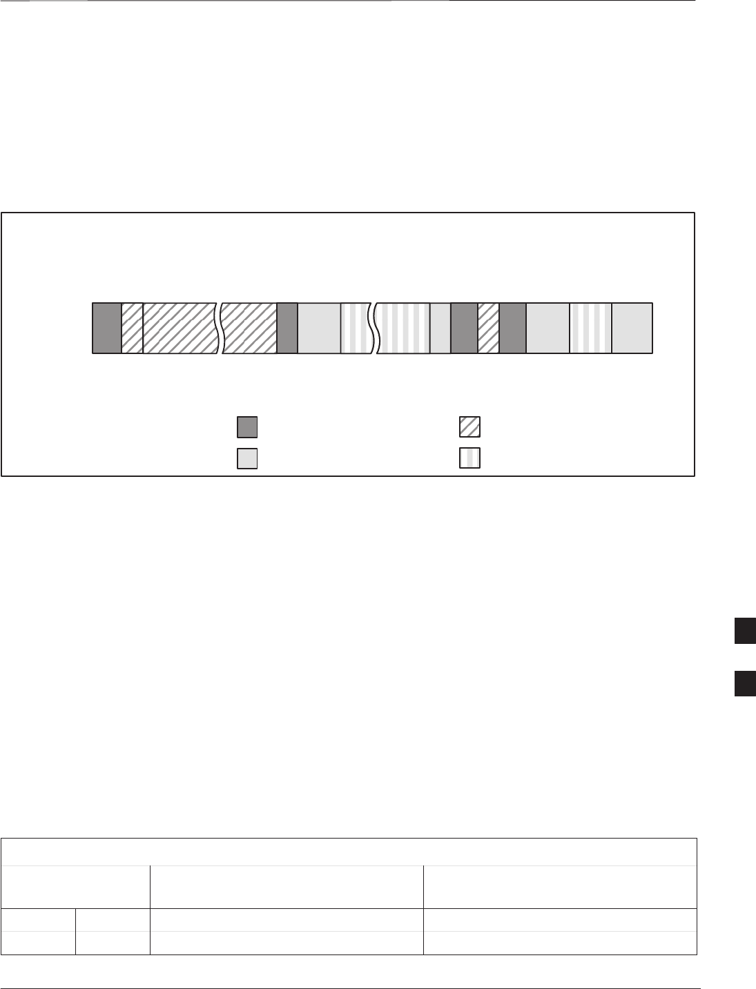
CDMA Operating Frequency Programming Information – North American
PCS Bands – continued
DEC 2000 7-51
SCt300 BTS Hardware Installation, ATP and FRU Procedures
PRELIMINARY
800 MHz CDMA Channels
Figure 7-16 shows the valid channels for the North American cellular
telephone frequency spectrum. There are 10 CDMA wireline or
non–wireline band channels used in a CDMA system (unique per
customer operating system).
Figure 7-16: North American Cellular Telephone System Frequency Spectrum (CDMA Allocation).
RX FREQ
(MHz)
991
1023
1
333
334
666
667
716
717
799
CHANNEL
OVERALL NON–WIRELINE (A) BANDS
OVERALL WIRELINE (B) BANDS
824.040
825.000
825.030
834.990
835.020
844.980
845.010
846.480
846.510
848.970
869.040
870.000
870.030
879.990
880.020
889.980
890.010
891.480
891.510
893.970
TX FREQ
(MHz)
1013
694
689
311
356
644
739
777
CDMA NON–WIRELINE (A) BAND
CDMA WIRELINE (B) BAND
FW00402
Calculating 800 MHz Center
Frequencies
Table 7-28 shows selected 800 MHz CDMA candidate operating
channels, listed in both decimal and hexadecimal, and the corresponding
transmit, and receive frequencies. Center frequencies (in MHz) for
channels not shown in the table may be calculated as follows:
SChannels 1–777
TX = 870 + 0.03 * Channel#
Example: Channel 262
TX = 870 + 0.03*262 = 877.86 MHz
SChannels 1013–1023
TX = 870 + 0.03 * (Channel# – 1023)
Example: Channel 1015
TX = 870 +0.03 *(1015 – 1023) = 869.76 MHz
SRX = TX – 45 MHz
Example: Channel 262
RX = 877.86 –45 = 832.86 MHz
Table 7-28: 800 MHz TX and RX Frequency vs. Channel
Channel Number
Decimal Hex Transmit Frequency (MHz)
Center Frequency Receive Frequency (MHz)
Center Frequency
1 0001 870.0300 825.0300
25 0019 870.7500 825.7500
. . . continued on next page
7

CDMA Operating Frequency Programming Information – North American
PCS Bands – continued
PRELIMINARY
SCt300 BTS Hardware Installation, ATP and FRU Procedures DEC 2000
7-52
Table 7-28: 800 MHz TX and RX Frequency vs. Channel
Channel Number
Decimal Hex Receive Frequency (MHz)
Center Frequency
Transmit Frequency (MHz)
Center Frequency
50 0032 871.5000 826.5000
75 004B 872.2500 827.2500
100 0064 873.0000 828.0000
125 007D 873.7500 828.7500
150 0096 874.5000 829.5000
175 00AF 875.2500 830.2500
200 00C8 876.0000 831.0000
225 00E1 876.7500 831.7500
250 00FA 877.5000 832.5000
275 0113 878.2500 833.2500
300 012C 879.0000 834.0000
325 0145 879.7500 834.7500
350 015E 880.5000 835.5000
375 0177 881.2500 836.2500
400 0190 882.0000 837.0000
425 01A9 882.7500 837.7500
450 01C2 883.5000 838.5000
475 01DB 884.2500 839.2500
500 01F4 885.0000 840.0000
525 020D 885.7500 840.7500
550 0226 886.5000 841.5000
575 023F 887.2500 842.2500
600 0258 888.0000 843.0000
625 0271 888.7500 843.7500
650 028A 889.5000 844.5000
675 02A3 890.2500 845.2500
700 02BC 891.0000 846.0000
725 02D5 891.7500 846.7500
750 02EE 892.5000 847.5000
775 0307 893.2500 848.2500
NOTE
Channel numbers 778 through 1012 are not used.
1013 03F5 869.7000 824.7000
1023 03FF 870.0000 825.0000
7

TX & RX Acceptance Tests
DEC 2000 7-53
SCt300 BTS Hardware Installation, ATP and FRU Procedures
PRELIMINARY
TX ATP Test
Refer to Table 7-29 to perform a TX ATP test. This procedure assumes
that the site specific CDF file is in the wlmf\cdma\bts–# folder.
The ALL TX list performs the following ATP tests:
1. TX Mask
2. Rho
3. Pilot Time Offset
4. Code Domain Power
Prerequisites
You must successfully complete all the procedures outlined in previous
chapters before you attempt to run an ATP.
Table 7-29: TX Acceptance Test Outline
Step Action
1Set up test equipment for TX tests per Figure 7-17 or Figure 7-18.
2Perform the following to run TX Acceptance Tests:
– Select the MAWI.
– Click on the Tests menu
– Select ALL TX.
* IMPORTANT
The DPLL must be tracking either GPS or HSO.
TX Tests Using Backup
Synchronization (Sites
Equipped With GPS)
Follow the steps in Table 7-30 to perform the TX test using backup
synchronization.
Table 7-30: TX Test Using Backup Synchronization
Step Action
1If logged into the BTS with the LMF, then logout.
2Open an MMI Communication session.
3Verify that the BTS is in OOS_RAM status by entering the status command.
4Simulate an LMF connection by entering the sndtype 0xa178 command.
. . . continued on next page
7

TX & RX Acceptance Tests – continued
PRELIMINARY
SCt300 BTS Hardware Installation, ATP and FRU Procedures DEC 2000
7-54
Table 7-30: TX Test Using Backup Synchronization
Step Action
5At the MMI prompt, enter dpll_info and verify that GPS and HSO are good reference sources.
Observe the following typical response:
current dpll task state info:
dpll task state: DPLL_LOCKED
global cdma time: enabled
local cdma time: disabled
Reference Ref_Status Ref_select Even_select(DPLL’s Ref source)
GPS TRUE TRUE TRUE
HSO TRUE FALSE FALSE
FREERUN FALSE FALSE FALSE
2SEC FALSE FALSE FALSE
The Ref_Status for the GPS and HSO must be TRUE. The Ref_select must be TRUE and
FALSE for the GPS and HSO, respectively.
6Verify that the HSO takes over for the GPS by simulating a failure of the GPS through software.
Simulate the GPS losing all tracked satellites by entering the gps_rx_debug nosats on
command at the MMI prompt. Observe the following typical response:
FM: #2716 Ticks=00140aab pc=08137df4 nid=30003004 org=6
info=09e200270000 file=gps_misc.c line=3904
send gps no sats SET –seeing no tracked sats.
7At the MMI prompt, enter dpll_info and verify that the BTS is now using the HSO as the
primary reference source. The Ref_select must be FALSE and TRUE for the GPS and HSO,
respectively.
8Enter the dpll_status command to display the current state of the DPLL. Observe the following
typical response.
Current source set to: HSO reference
DPLL control task state: DPLL track
DPLL status (not valid if using even sec src):
c:6CD6 off: –9697314,25154,8669797 TK
Mode cntr: 60
ip: 3, iq: –9
aip1: 9, aiq1: 4
aip2: 6, aiq2: –2
tip: 3, tiq: –9
integrator: –2511864
9Verify that the DPLL is “tracking” the HSO. The Current source set to field should
read HSO reference. The DPLL control task state field should read DPLL
track.
10 Exit the MMI communication session and login to the BTS with the LMF.
11 Under the JCdma menu, perform the JCdma Carrier and Jcdma PtOff tests to verify that the
BTS passes using the HSO as the backup synchronization source.
12 Logout of the BTS.
. . . continued on next page
7

TX & RX Acceptance Tests – continued
DEC 2000 7-55
SCt300 BTS Hardware Installation, ATP and FRU Procedures
PRELIMINARY
Table 7-30: TX Test Using Backup Synchronization
Step Action
13 If logged into the BTS with the LMF, then logout.
14 Open an MMI Communication session.
15 Verify that the BTS is in OOS_RAM status by entering the status command.
16 Simulate an LMF connection by entering the sndtype 0xa178 command.
17 Disable the simulation of the GPS losing tracked satellites by entering the gps_rx_debug
nosats off command at the MMI prompt.
NOTE
NOTE
The gps_rx_debug command simulates the “No Satellites Tracked” condition. In reality, the
receiver is tracking satellites. However, the software is masking that information. Be sure to turn
off the “No Satellites” condition after completing this test.
18 Follow the procedure in Table 7-9 (Synchronization Verification) to insure the BTS is tracking the
RGPS.
RX ATP Test
Refer to Table 7-31 to perform an RX ATP test. This procedure assumes
that the site specific CDF file is in the wlmf\cdma\bts–# folder.
Table 7-31: RX ATP Test
Step Action
1Set up test equipment per Figure 7-19 or Figure 7-20.
2Terminate diversity RX antenna inputs on FRU.
3Enter the following commands to run the RX Acceptance Tests.
– Select the MAWI.
– Click on the Tests menu.
– Select ALL RX.
NOTE
The LMF refers to the antennas as Main and Diversity. On a Microcell, the Main is Antenna B
and the Diversity is Antenna A. On a Picocell, the Main is Antenna A and there is no Diversity or
Antenna B.
NOTE
Select Both in the RX Branch pick list if a diversity antenna is used.
7
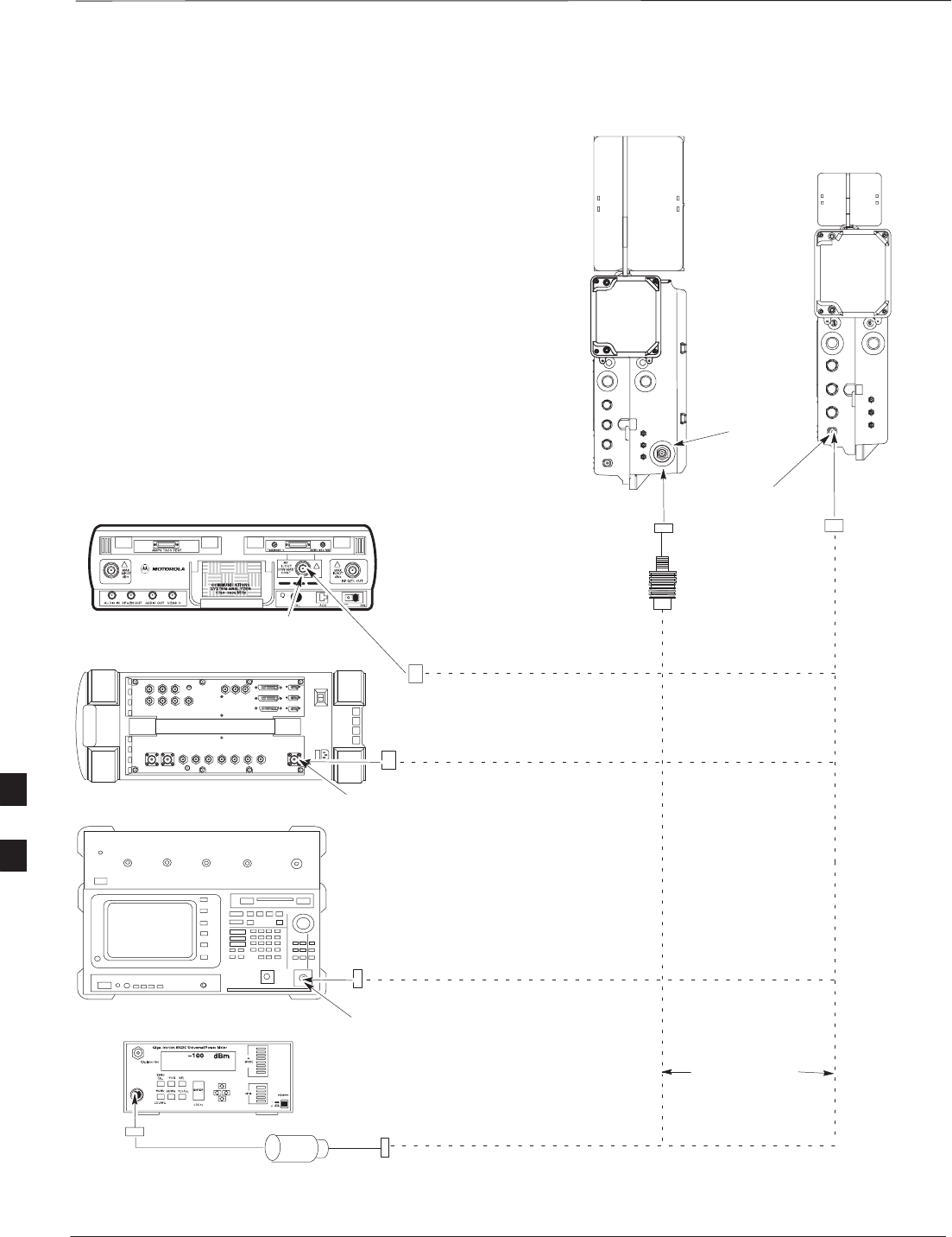
TX & RX Acceptance Tests – continued
PRELIMINARY
SCt300 BTS Hardware Installation, ATP and FRU Procedures DEC 2000
7-56
Figure 7-17: TX ATP Setup (CyberTest, HP 8935 and Advantest R3465
COMMUNICATIONS TEST SET
PICOCELL
UNIT
MICROCELL
UNIT
ANTENNA A
ANTENNA B
30DB IN-LINE
ATTENUATOR
FOR MICROCELL
NO ATTENUATOR
REQUIRED
FOR PICOCELL
TRANSMIT RF
TEST CABLE
POWER SENSOR NOTE: THE DOTTED LINES REPRESENT THAT
EITHER TX RF TEST CABLE CONNECTS TO
BOTH COMMUNICATIONS TEST SET AND
POWER METER
MOTOROLA CYBERTEST
HP 8935
ADVANTEST MODEL R3465
RF IN/OUT
RF IN/OUT
INPUT
50–OHM
POWER METER: GIGATRONICS
8541C OR HP 437B
7
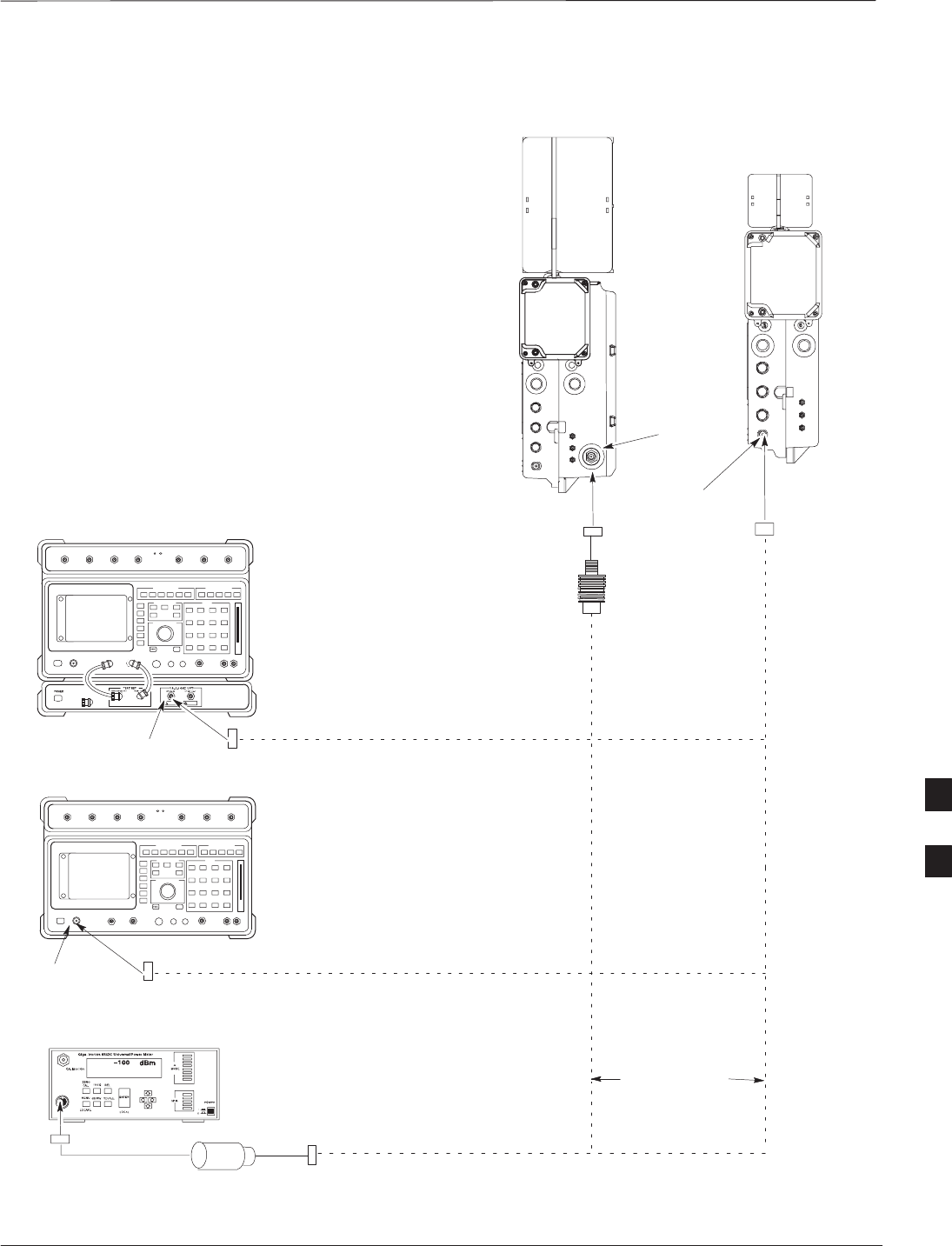
TX & RX Acceptance Tests – continued
DEC 2000 7-57
SCt300 BTS Hardware Installation, ATP and FRU Procedures
PRELIMINARY
Figure 7-18: TX ATP Setup (HP 8921A)
COMMUNICATIONS TEST SET
PICOCELL
UNIT
MICROCELL
UNIT
ANTENNA A
ANTENNA B
POWER METER: GIGATRONICS
8541C OR HP 437B
30DB IN-LINE
ATTENUATOR
FOR MICROCELL
NO ATTENUATOR
REQUIRED
FOR PICOCELL
TRANSMIT RF
TEST CABLE
POWER SENSOR NOTE: THE DOTTED LINES REPRESENT THAT
EITHER TX RF TEST CABLE CONNECTS TO
BOTH COMMUNICATIONS TEST SET AND
POWER METER
Hewlett–Packard Model HP 8921A W/PCS Interface
(for 1700 and 1900 MHz)
RF
IN/OUT
Hewlett–Packard Model HP 8921A (for
800 MHz)
RF
IN/OUT
7
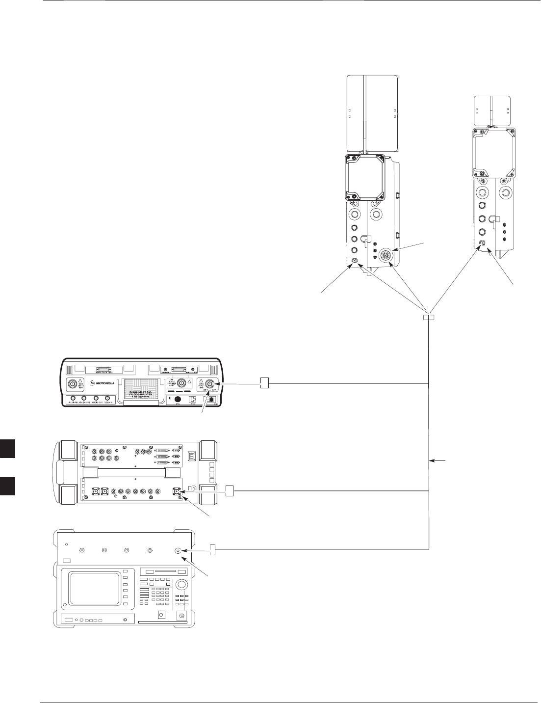
TX & RX Acceptance Tests – continued
PRELIMINARY
SCt300 BTS Hardware Installation, ATP and FRU Procedures DEC 2000
7-58
Figure 7-19: RX ATP Setup (CyberTest, HP 8935 and Advantest)
COMMUNICATIONS TEST SET
PICOCELL
UNIT
MICROCELL
UNIT
ANTENNA A
(MAIN)
ANTENNA B
(MAIN)
RECEIVE RF
TEST CABLE
MOTOROLA CYBERTEST
HP 8935 (REAR VIEW)
ADVANTEST MODEL R3465
RF GEN OUT
RF IN/OUT
RF OUT
ANTENNA A
(DIVERSITY)
7
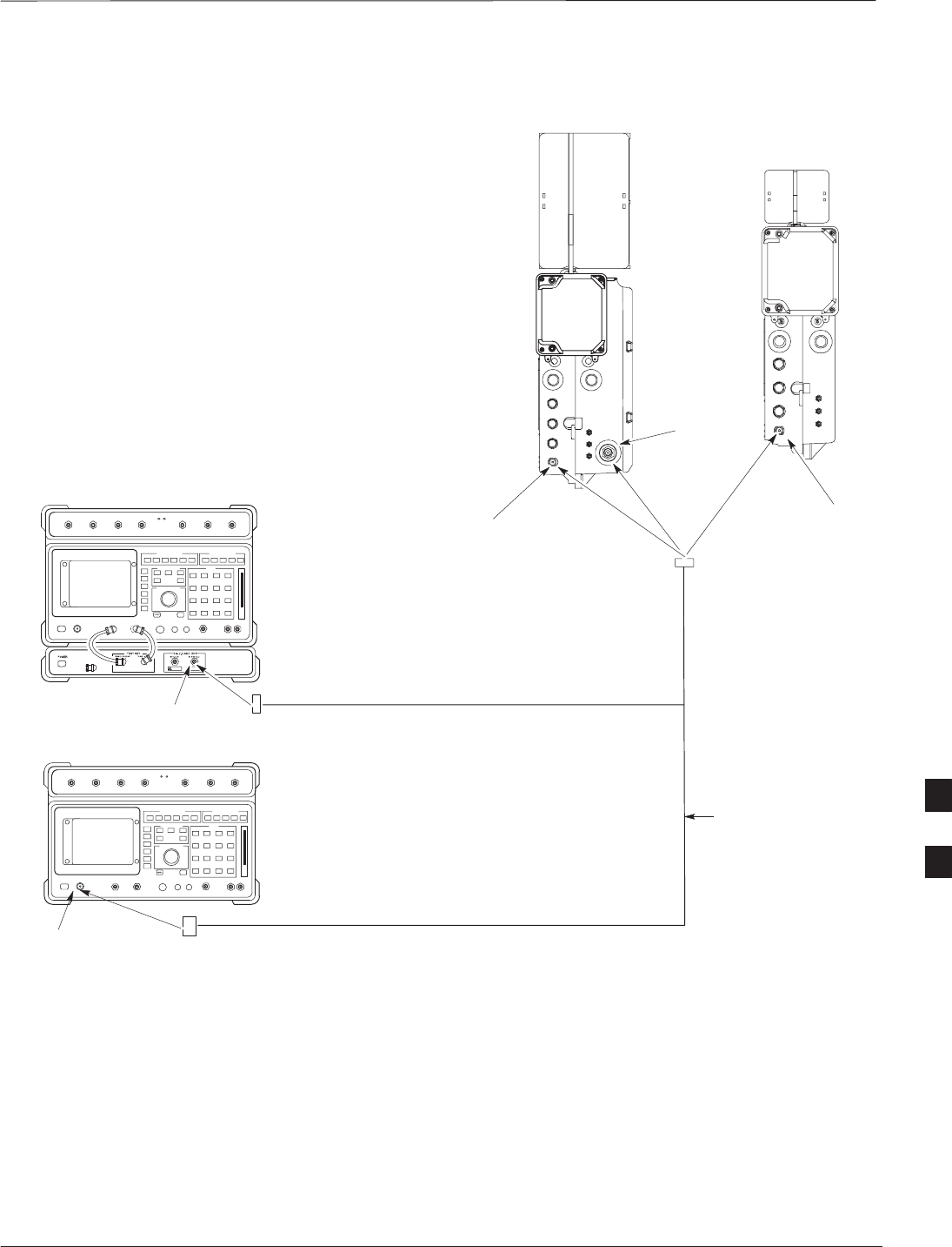
TX & RX Acceptance Tests – continued
DEC 2000 7-59
SCt300 BTS Hardware Installation, ATP and FRU Procedures
PRELIMINARY
Figure 7-20: RX ATP Setup (HP 8921A)
COMMUNICATIONS TEST SET
PICOCELL
UNIT
MICROCELL
UNIT
ANTENNA A
(MAIN)
ANTENNA B
(MAIN)
RECEIVE RF
TEST CABLE
ANTENNA A
(DIVERSITY)
Hewlett–Packard Model HP 8921A W/PCS Interface
(for 1700 and 1900 MHz)
RF OUT ONLY
Hewlett–Packard Model HP 8921A
(for 800 MHz)
RF
IN/OUT
7

Generate an ATP Report
PRELIMINARY
SCt300 BTS Hardware Installation, ATP and FRU Procedures DEC 2000
7-60
Background
Each time an ATP test is run, an ATP report is updated to include the
results of the most recent ATP tests if the Save Results button is used
to close the status report window. The ATP report will not be updated if
the status reports window is closed with use of the Dismiss button.
ATP Report
A separate report is created for each BTS and includes the following for
each test:
STest name
SPASS or FAIL
SDescription information (if applicable)
SMAWI number
SChannel number
SCarrier number
SSector number
SUpper test limit
SLower test limit
STest result
STime stamp
SDetails/Warning information (if applicable)
Follow the procedures in Table 7-32 to view and create a printable file
for the ATP report of a BTS.
Table 7-32: Generate an ATP Report
Step Action
1Click on the Login tab if it is not in the forefront.
2Select the desired BTS from the Available Base Stations pick list.
3Click on the Report button.
4Start the report if desired by clicking on a column heading.
5Click on the Dismiss button if you do not want to create a printable file copy.
6To create a printable file, select the desired file type in the picklist and then click on the Save
button.
Refer to the LMF help screens, or the CDMA LMF
Operator’s Guide, 68P64114A21, for information on how
to print an ATP report.
NOTE
7

Copy LMF CAL File to CBSC
DEC 2000 7-61
SCt300 BTS Hardware Installation, ATP and FRU Procedures
PRELIMINARY
Overview
After you perform the ATP you must move a copy of the CAL file for
the BTS from the LMF to the CBSC. This is normally done by putting a
copy of the CAL file on a floppy disk and then using the floppy disk to
move the CAL file to the CBSC.
Prerequisites
You must complete the following steps before you copy the LMF CAL
file to the CBSC:
SA DOS formatted 1.44 MB 3 1/2–in. floppy disk is necessary to do
this procedure.
SThe ATP and Audit procedures have successfully been performed.
SThe Create CAL File procedure was performed.
SYou logged out of the BTS.
Copying CAL Files from LMF to
a Diskette
Follow the procedure in Table 7-33 to copy CAL files from an LMF
computer to a 3.5 diskette.
Table 7-33: Copy Files from LMF to a Diskette
Step Action
1Insert a diskette into your Windows A: drive.
NOTE
If your diskette has not been formatted, format it using Windows. The diskette must be DOS
formatted before copying any files. Consult your Windows/DOS documentation or online help on
how to format diskettes.
2Click on the bold Start button to launch the Windows Explorer program from your
Programs menu list.
3Click on your C: drive
4Double click on the wlmf folder.
5Double–click on the CDMA folder
6Double click on the bts–# folder for the file you want to copy.
7Drag the file (for example, BTS–#.cal, BTS–#.txt, BTS–#.htm, BTS–#.xls) to the
3–1/2–in. floppy (A:) icon on the top left of the screen and release the mouse button.
8Repeat step 6 and 7 until you have copied each file desired and close the Windows Explorer
program by selecting Close from the File menu option.
7

Copy LMF CAL File to CBSC – continued
PRELIMINARY
SCt300 BTS Hardware Installation, ATP and FRU Procedures DEC 2000
7-62
Copying CAL Files from
Diskette to the CBSC
Follow the procedures in Table 7-34 to copy CAL file from a diskette to
the CBSC.
Table 7-34: Copying CAL Files from Diskette to the CBSC
Step Action
1Log in to the CBSC on the OMC–R Unix workstation using your account name and password.
2Place your diskette containing calibration file(s) in the workstation diskette drive.
3Type in eject –q and press the Enter key.
4Type in mount and press the Enter key.
NOTE
SCheck to see that the message floppy/no_name is displayed on the last line.
SIf the eject command was previously entered, floppy/no_name will be appended with a
number. Use the explicit floppy/no_name reference displayed.
5Type in cd /floppy/no_name and press the Enter key.
6Type in ls –lia and press the Enter key. Verify that the bts–#.cal file is on the diskette.
7Type in cd and press the Enter key.
8Type in pwd and press the Enter key. Verify you are in your home directory (/home/<name> ).
9 With Solaris versions of Unix, create a Unix–formatted version of the bts–#.cal file in your home
directory by entering the following command:
dos2unix /floppy/no_name/bts–#.cal bts–#.cal and press the Enter key
(where # is BTS number).
NOTE
Other versions of Unix do not support the dos2unix command. In these cases, use the Unix cp
(copy) command. The copied files will contain DOS line feed characters which must be edited out
with a Unix text editor.
10 Type in ls –l *.cal and press the Enter key. Verify the cal files have been copied.
11 Type in eject and press the Enter key.
12 Remove the diskette from the workstation.
7

Prepare to Leave the Site
DEC 2000 7-63
SCt300 BTS Hardware Installation, ATP and FRU Procedures
PRELIMINARY
Removing External Test
Equipment Perform the procedure in Table 7-35 to disconnect the test equipment
and prepare the BTS for active service.
Table 7-35: Remove External Test Equipment
Step Action
1Disconnect all test equipment from the antenna connectors on the BTS.
2Reconnect and visually inspect all antenna feed lines on the BTS.
3Disconnect all test equipment from the diagnostic access area.
Reset and Initialize Site
Remotely
The BTS should not be left with data and code loaded from the CDMA
LMF. The configuration data and code loads used for normal operation
could be different from those stored in the CDMA LMF files. By
resetting the BTS, the required data and code can be loaded from the
CBSC when spans are again active.
To reset the BTS and have the OMCR/CBSC bring up the site remotely,
perform the procedure in Table 7-36.
Table 7-36: Reset BTS and Remote Site Initialization
Step Action
1Terminate the CDMA LMF session by following the procedures in Table 7-38.
2Use the AC and DC power breakers to cycle BTS power off and on.
3Notify the OMCR/CBSC to take control of the site and download code and data to the BTS.
4Verify the CBSC can communicate with the MAWI.
Bringing BTS into Service with
the CDMA LMF
Whenever possible, have the OMCR/CBSC enable the
BTS.
IMPORTANT
*
If code and/or data could not be loaded remotely from the
OMCR/CBSC, follow the steps outlined in Table 7-37 as required to
bring the BTS from the OOS to INS mode.
7

Prepare to Leave the Site – continued
PRELIMINARY
SCt300 BTS Hardware Installation, ATP and FRU Procedures DEC 2000
7-64
Table 7-37: Bring BTS into Service
Step Action
1On the CDMA LMF, select the MAWI.
2Click on Device from the menu bar.
3Click on Enable from the Device menu. A status report window is displayed.
4 Click Cancel to close the transceiver parameters window, if applicable.
5 Click OK to close the status report window.
The selected devices that successfully change to INS change color to green.
Terminating LMF
Session/Removing Terminal
Perform the procedure in Table 7-38 to terminate the LMF session and
remove the CDMA LMF computer.
Table 7-38: Remove LMF
Step Action
! CAUTION
Do not power down the CDMA LMF terminal without performing the procedure below.
Corrupted/lost data files may result.
1Log out of all BTS sessions and exit CDMA LMF by clicking on the File selection in the menu bar
and selecting Exit from the File menu list.
2 Click Yes in the Confirm Logout pop–up message which appears.
3In the Windows Task Bar, click Start and select Shutdown.
4 Click Yes when the Shut Down Windows message appears.
5Wait for the system to shut down and the screen to go blank.
6Disconnect the CDMA LMF terminal serial cable from the BTS.
7Disconnect the CDMA LMF terminal serial port, the RS–232–IEEE488 converter and the GPIB
cables as required for equipment transport.
7
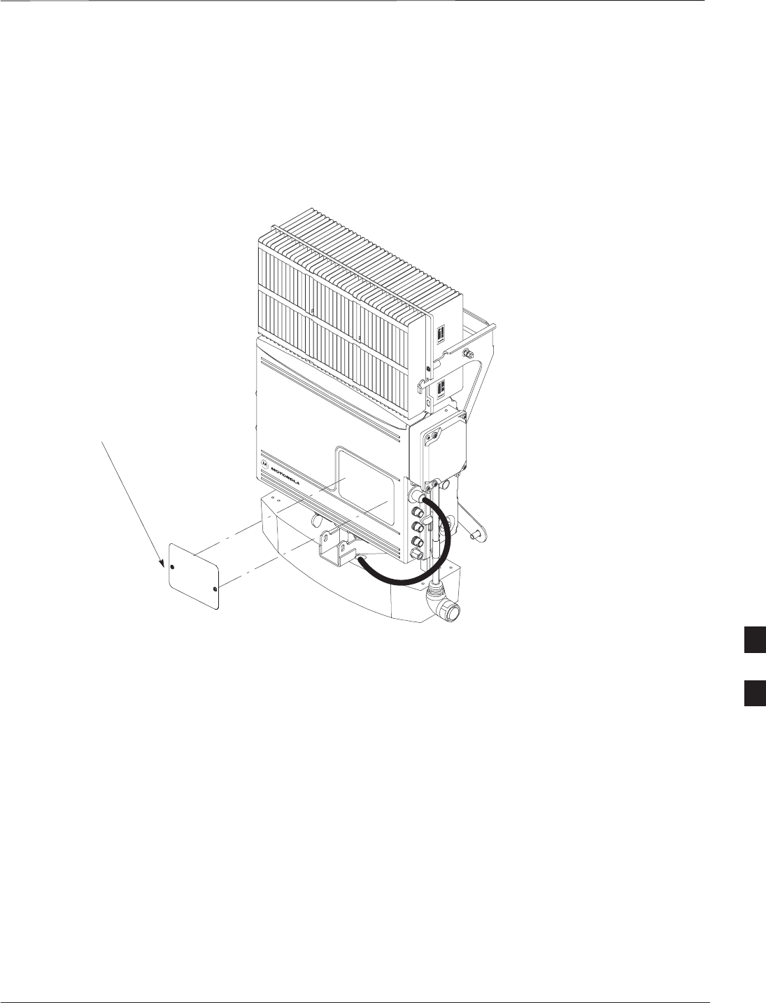
Prepare to Leave the Site – continued
DEC 2000 7-65
SCt300 BTS Hardware Installation, ATP and FRU Procedures
PRELIMINARY
Replace Diagnostic Access
Cover
Use a T20 Torx tamper bit to tighten the two tamper–resistant M4
screws holding the cover. Torque to 10 in–lb. Refer to Figure 7-21.
Figure 7-21: How To Replace The Diagnostic Access Cover (Microcell shown)
SCREWS IN DIAGNOSTIC
ACCESS COVER ARE CAPTIVE
Replace Solar Cover
Replace the solar cover. Refer to the “Powering on Unit and Mounting
the Solar Cover” procedure in Chapter 5.
7

Prepare to Leave the Site – continued
PRELIMINARY
SCt300 BTS Hardware Installation, ATP and FRU Procedures DEC 2000
7-66
Notes
7

DEC 2000 SCt300 BTS Hardware Installation, ATP and FRU Procedures
PRELIMINARY
Chapter 8: Optimization and Optional Acceptance Test Procedures (ATP)
for Frequency Hopping Pilot Beacon (FHPB)
Table of Contents
ATP Overview 8-1. . . . . . . . . . . . . . . . . . . . . . . . . . . . . . . . . . . . . . . . . . . . . . . . . . .
Overview 8-1. . . . . . . . . . . . . . . . . . . . . . . . . . . . . . . . . . . . . . . . . . . . . . . .
FHPB ATP Prerequisites 8-1. . . . . . . . . . . . . . . . . . . . . . . . . . . . . . . . . . . .
Create CAL File 8-2. . . . . . . . . . . . . . . . . . . . . . . . . . . . . . . . . . . . . . . . . . . . . . . . .
Overview 8-2. . . . . . . . . . . . . . . . . . . . . . . . . . . . . . . . . . . . . . . . . . . . . . . .
Create CAL File 8-2. . . . . . . . . . . . . . . . . . . . . . . . . . . . . . . . . . . . . . . . . . .
Procedure 8-3. . . . . . . . . . . . . . . . . . . . . . . . . . . . . . . . . . . . . . . . . . . . . . . .
RF Path Audit 8-4. . . . . . . . . . . . . . . . . . . . . . . . . . . . . . . . . . . . . . . . . . . . . . . . . . .
Test Equipment Setup 8-4. . . . . . . . . . . . . . . . . . . . . . . . . . . . . . . . . . . . . .
Transmit (TX) Audit 8-4. . . . . . . . . . . . . . . . . . . . . . . . . . . . . . . . . . . . . . .
Acceptance Tests 8-6. . . . . . . . . . . . . . . . . . . . . . . . . . . . . . . . . . . . . . . . . . . . . . . . .
TX Test Objective 8-6. . . . . . . . . . . . . . . . . . . . . . . . . . . . . . . . . . . . . . . . .
TX Tests to be Performed 8-6. . . . . . . . . . . . . . . . . . . . . . . . . . . . . . . . . . .
TX Acceptance Tests 8-8. . . . . . . . . . . . . . . . . . . . . . . . . . . . . . . . . . . . . . . . . . . . .
TX ATP Test 8-8. . . . . . . . . . . . . . . . . . . . . . . . . . . . . . . . . . . . . . . . . . . . .
Prerequisites 8-8. . . . . . . . . . . . . . . . . . . . . . . . . . . . . . . . . . . . . . . . . . . . . .
TX Tests Using Backup Synchronization (Sites Equipped With GPS) 8-8.
Generate an ATP Report 8-11. . . . . . . . . . . . . . . . . . . . . . . . . . . . . . . . . . . . . . . . . . .
Background 8-11. . . . . . . . . . . . . . . . . . . . . . . . . . . . . . . . . . . . . . . . . . . . . .
ATP Report 8-11. . . . . . . . . . . . . . . . . . . . . . . . . . . . . . . . . . . . . . . . . . . . . .
Copy LMF CAL File to CBSC 8-12. . . . . . . . . . . . . . . . . . . . . . . . . . . . . . . . . . . . .
Overview 8-12. . . . . . . . . . . . . . . . . . . . . . . . . . . . . . . . . . . . . . . . . . . . . . . .
Copying CAL Files from LMF to a Diskette 8-12. . . . . . . . . . . . . . . . . . . .
Copying CAL Files from Diskette to the CBSC 8-13. . . . . . . . . . . . . . . . . . 8

Table of Contents – continued
PRELIMINARY
SCt300 BTS Hardware Installation, ATP and FRU Procedures DEC 2000
Notes
8

ATP Overview
DEC 2000 8-1
SCt300 BTS Hardware Installation, ATP and FRU Procedures
PRELIMINARY
Overview
The purpose of this procedure is to outline the optimization and ATP
procedure for a unit configured as a Frequency Hopping Pilot Beacon
(FHPB).
This feature offers the ability to configure a standard SC300 MicroCell
or PicoCell as a frequency hopping pilot beacon. The FHPB serves the
same role in initiating mobile–assisted hard handoff as a conventional
pilot beacon. However, the FHPB serves tp to six carriers in a time
division multiplexed fashion. This reduces the number of forward link
transmitters required.
The SC300 FHPB serves as a Pilot Beacon only. It transmits a fixed list
of overhead messages on the paging and synch channels. It does not
carry traffic as a stand–alone entity.
The SC300 FHPB is configured, downloaded, initialized, maintained
and diagnosed via the OMC–R. The FHPB cannot be configured by the
LMF. The LMF can be used to download code and data, inspect FHPB
parameters, and exeute ATP test procedures.
The FHPB is connected to the OMC–R either via span line or by the
multi–BTS configuration.
All the procedures in this chapter are to be performed with the BTS out
of service or under LMF control. If necessary, refer to the “Shut Down
and Restoring BTS Signaling” procedure in Chapter 7.
For a complete listing of the required tools and equipment, refer to the
“ATP Tools and Equipment” list in Chapter 1.
FHPB ATP Prerequisites
You must complete the following ATP procedues before you do the
FHPB ATP. Refer to the Optimization and Optional Acceptance Test
Procedures (ATP) in Chapter 7 of this manual.
1. BTS preparation.
2. Connecting the LMF to the BTS.
3. Connecting test equipment to the BTS and LMF.
4. Establishing an MMI communications session.
5. Setting customer operating channel.
6. Synchronization verification.
7. Install LMF program and binaries.
8. Start LMF and log on to BTS.
8

Create CAL File
PRELIMINARY
SCt300 BTS Hardware Installation, ATP and FRU Procedures DEC 2000
8-2
Overview
Use this procedure to create a CAL file for the Calibration audit. You
must do this procedure before the RF path audit.
Create CAL File
The Create CAL File function gets the BLO data from the MAWI and
creates/updates the CAL file for the BTS. If a CAL file does not exist, a
new one is created. If a CAL file already exists, it is updated. The BTS
is calibrated at the factory and normally does not require calibration after
installation, so you must use the Create CAL File function to create a
CAL file since TX calibration is not performed.
The Create CAL File function only applies to selected
(highlighted) MAWIs.
NOTE
The user is not encouraged to edit the CAL file as this
action can cause interface problems between the BTS and
the LMF. To manually edit the CAL file, you must first
logout of the BTS. If you manually edit the CAL file and
then use the Create CAL File function, the edited
information is lost.
NOTE
Prerequisites
You must do the following steps before you run this test:
SThe MAWI has the correct code load and data load.
SThe MAWI is INS.
SThe LMF is logged on to the BTS.
8

Create CAL File – continued
DEC 2000 8-3
SCt300 BTS Hardware Installation, ATP and FRU Procedures
PRELIMINARY
Procedure
Use the following procedure in Table 8-1 to create a CAL file.
Table 8-1: Create CAL File
Step Action
1Log on to the BTS if you have not already done so.
2Select the MAWI.
3Click on the Device menu.
4Click on the Create Cal File menu item.
The status report window displays the results of the action.
5 Click OK.
The bts–#.cal is located in the wlmf\cdma\bts–#
folder (where # is the number of the BTS).
NOTE
8
RF Path Audit
PRELIMINARY
SCt300 BTS Hardware Installation, ATP and FRU Procedures DEC 2000
8-4
Test Equipment Setup
The BTS RF path is calibrated in the factory. There is no need to
calibrate during installation.
All tests are measured with respect to the Antenna output
connector. Additional losses must be compensated for. RF
calibration does not take the following into consideration:
– Antenna feedline losses.
– Antenna gain.
IMPORTANT
*
Transmit (TX) Audit
Prerequisites
You must complete the following steps before you do the TX RF path
audit:
1. MAWI has correct code load and data load.
2. MAWI is INS.
3. Test equipment and test cables are calibrated and connected to the
TX antenna outputs.
4. LMF is logged into the BTS.
Procedure
Follow the steps in Table 8-2 to audit the calibration.
To prevent damage to the test equipment all transmit (TX)
test connections must be via the 30 dB in-line attenuator
for the MicroCell BTS.
CAUTION
The TX audit actions can be performed separately by using
the applicable Device menu selections.
NOTE
8

RF Path Audit – continued
DEC 2000 8-5
SCt300 BTS Hardware Installation, ATP and FRU Procedures
PRELIMINARY
Table 8-2: RF Path Audit
Step Action
1Configure test equipment for TX path calibration according to NO TAG.
2Select the MAWI. Select Tests>All Cal/Audit.
3Type the appropriate channel number in the Carrier n Channels box.
4 Click OK.
5Follow the cable connection directions as they are displayed. The test results will be displayed in the
status report window.
6 Click OK to close the status report widow.
8

Acceptance Tests
PRELIMINARY
SCt300 BTS Hardware Installation, ATP and FRU Procedures DEC 2000
8-6
TX Test Objective
The following tests will verify the TX antenna path. Output power
control will also be verified. All tests will be performed using the power
meter and communication test set. Measurements will be via the
Antenna A (Picocell) and Antenna B (Microcell) connectors.
You must remove the antenna cables before you perform
the ATP.
NOTE
The BTS is keyed up to generate a CDMA carrier at 31 dBm for
MicroCell and 17 dBm for PicoCell.
TX Tests to be Performed
The following TX tests will be performed to verify the CDMA Forward
Link.
Near band & in band spurious emissions and occupied
bandwidth
You will verify that the transmitted CDMA carrier waveform generated
meets the Spurious Emissions specification (transmit spectral mask and
Occupied Bandwidth as defined in ARIB STD–T53) with respect to
either a pre–determined test pattern or test pattern generated by using
assigned cdf file values.
–+/– 750 kHz from center frequency to +/– 1980 kHz from center
frequency – at least –45 dBc
–+/– 1980 kHz from center frequency and out – at least –60 dBc
– all near band and out of band spurious emissions are verified to be
less than or equal to –60 dBc relative to reference power (measured
previously as total power).
Waveform quality (Rho) and pilot time tolerance (offset)
You will verify that the transmitted Pilot channel waveform quality (rho)
exceeds the minimum specified value in ARIB STD T53. Rho
represents the correlation between actual and perfect CDMA modulation
spectrum. 1.0000 represents 100% (or perfect correlation).
– Waveform quality (Rho) should be > 0.912 (–0.4 dB).
The Pilot Time Tolerance (Offset) is the difference between the CDMA
analyzer measurement interval (based on the BTS system time reference)
and the incoming block of transmitted data from the BTS (Pilot only,
Walsh code 0)
– Pilot Time Tolerance (Offset) should be < 10 uS. (< 3 uS typical)
CDMA carrier frequency verification
You will verify the frequency of the transmitted CDMA carrier signal to
be within 0.05 ppm.
8

Acceptance Tests – continued
DEC 2000 8-7
SCt300 BTS Hardware Installation, ATP and FRU Procedures
PRELIMINARY
Code domain power noise, pilot power, and total power
You will verify that the code domain noise floor of all unused Walsh
codes within the CDMA spectrum measures < –27 dB (with respect to
total power). Pilot power will be verified to measure –7.04 dB +/–0.5
dB (with respect to standard test patterns). Total power will be verified
to measure +2/–4 dB (with respect to CDF specific file parameters).
BTS frequency accuracy
BTS frequency accuracy can be verified manually during normal
operation by monitoring the 19.6608 MHz reference (19 MHz) from the
Diagnostic Access Area. A frequency counter with an accuracy of +/–
0.005 ppm can be used to check the BTS frequency accuracy.
8

TX Acceptance Tests
PRELIMINARY
SCt300 BTS Hardware Installation, ATP and FRU Procedures DEC 2000
8-8
TX ATP Test
Refer to Table 8-3 to perform a TX ATP test. This procedure assumes
that the site specific CDF file is in the wlmf\cdma\bts–# folder.
The ALL TX list performs the following ATP tests:
1. TX Mask
2. Rho
3. Pilot Time Offset
4. Code Domain Power
Prerequisites
Before attempting to run an ATP, all procedures outlined in previous
chapters should have been successfully completed.
Table 8-3: TX Acceptance Test Outline
Step Action
1Set up test equipment for TX tests per NO TAG.
2Perform the following to run TX Acceptance Tests:
– Select the MAWI.
– Click on the Tests menu
– Select ALL TX.
* IMPORTANT
The DPLL must be tracking either GPS or HSO.
TX Tests Using Backup
Synchronization (Sites
Equipped With GPS)
Follow the steps in Table 8-4 to perform the TX test using backup
synchronization.
Table 8-4: TX Test Using Backup Synchronization
Step Action
1If logged into the BTS with the LMF, then logout.
2Open an MMI Communication session.
3Verify that the BTS is in OOS_RAM status by entering the status command.
4Simulate an LMF connection by entering the sndtype 0xa178 command.
. . . continued on next page
8

TX Acceptance Tests – continued
DEC 2000 8-9
SCt300 BTS Hardware Installation, ATP and FRU Procedures
PRELIMINARY
Table 8-4: TX Test Using Backup Synchronization
Step Action
5At the MMI prompt, enter dpll_info and verify that GPS and HSO are good reference sources.
Observe the following typical response:
current dpll task state info:
dpll task state: DPLL_LOCKED
global cdma time: enabled
local cdma time: disabled
Reference Ref_Status Ref_select Even_select(DPLL’s Ref source)
GPS TRUE TRUE TRUE
HSO TRUE FALSE FALSE
FREERUN FALSE FALSE FALSE
2SEC FALSE FALSE FALSE
The Ref_Status for the GPS and HSO must be TRUE. The Ref_select must be TRUE and
FALSE for the GPS and HSO, respectively.
6Verify that the HSO takes over for the GPS by simulating a failure of the GPS through software.
Simulate the GPS losing all tracked satellites by entering the gps_rx_debug nosats on
command at the MMI prompt. Observe the following typical response:
FM: #2716 Ticks=00140aab pc=08137df4 nid=30003004 org=6
info=09e200270000 file=gps_misc.c line=3904
send gps no sats SET –seeing no tracked sats.
7At the MMI prompt, enter dpll_info and verify that the BTS is now using the HSO as the
primary reference source. The Ref_select must be FALSE and TRUE for the GPS and HSO,
respectively.
8Enter the dpll_status command to display the current state of the DPLL. Observe the following
typical response.
Current source set to: HSO reference
DPLL control task state: DPLL track
DPLL status (not valid if using even sec src):
c:6CD6 off: –9697314,25154,8669797 TK
Mode cntr: 60
ip: 3, iq: –9
aip1: 9, aiq1: 4
aip2: 6, aiq2: –2
tip: 3, tiq: –9
integrator: –2511864
9Verify that the DPLL is “tracking” the HSO. The Current source set to field should
read HSO reference. The DPLL control task state field should read DPLL
track.
10 Exit the MMI communication session and login to the BTS with the LMF.
11 Under the JCdma menu, perform the JCdma Carrier and Jcdma PtOff tests to verify that the
BTS passes using the HSO as the backup synchronization source.
12 Logout of the BTS.
. . . continued on next page
8

TX Acceptance Tests – continued
PRELIMINARY
SCt300 BTS Hardware Installation, ATP and FRU Procedures DEC 2000
8-10
Table 8-4: TX Test Using Backup Synchronization
Step Action
13 If logged into the BTS with the LMF, then logout.
14 Open an MMI Communication session.
15 Verify that the BTS is in OOS_RAM status by entering the status command.
16 Simulate an LMF connection by entering the sndtype 0xa178 command.
17 Disable the simulation of the GPS losing tracked satellites by entering the gps_rx_debug
nosats off command at the MMI prompt.
NOTE
NOTE
The gps_rx_debug command simulates the “No Satellites Tracked” condition. In reality, the
receiver is tracking satellites. However, the software is masking that information. Be sure to turn
off the “No Satellites” condition after completing this test.
18 Follow the procedure in Table 7-9 (Synchronization Verification) to insure the BTS is tracking the
RGPS.
8

Generate an ATP Report
DEC 2000 8-11
SCt300 BTS Hardware Installation, ATP and FRU Procedures
PRELIMINARY
Background
Each time an ATP test is run, an ATP report is updated to include the
results of the most recent ATP tests if the Save Results button is used
to close the status report window. The ATP report will not be updated if
the status reports window is closed with use of the Dismiss button.
ATP Report
A separate report is created for each BTS and includes the following for
each test:
STest name
SPASS or FAIL
SDescription information (if applicable)
SMAWI number
SChannel number
SCarrier number
SSector number
SUpper test limit
SLower test limit
STest result
STime stamp
SDetails/Warning information (if applicable)
Follow the procedures in Table 8-5 to view and create a printable file for
the ATP report of a BTS.
Table 8-5: Generate an ATP Report
Step Action
1Click on the Login tab if it is not in the forefront.
2Select the desired BTS from the Available Base Stations pick list.
3Click on the Report button.
4Start the report if desired by clicking on a column heading.
5Click on the Dismiss button if you do not want to create a printable file copy.
6To create a printable file, select the desired file type in the picklist and then click on the Save
button.
Refer to the LMF help screens, or the CDMA LMF
Operator’s Guide, 68P64114A21, for information on how
to print an ATP report.
NOTE
8

Copy LMF CAL File to CBSC
PRELIMINARY
SCt300 BTS Hardware Installation, ATP and FRU Procedures DEC 2000
8-12
Overview
After you perform the ATP you must move a copy of the CAL file for
the BTS from the LMF to the CBSC. This is normally done by putting a
copy of the CAL file on a floppy disk and then using the floppy disk to
move the CAL file to the CBSC.
Prerequisites
You must do the following steps before you copy the LMF CAL file to
the CBSC:
SA DOS formatted 1.44 MB 3 1/2–in. floppy disk is necessary to do
this procedure.
SThe ATP and Audit procedures have successfully been performed.
SThe Create CAL File procedure was performed.
SYou logged out of the BTS.
Copying CAL Files from LMF to
a Diskette
Follow the procedure in Table 8-6 to copy CAL files from an LMF
computer to a 3.5 diskette.
Table 8-6: Copy Files from LMF to a Diskette
Step Action
1Insert a diskette into your Windows A: drive.
NOTE
If your diskette has not been formatted, format it using Windows. The diskette must be DOS
formatted before copying any files. Consult your Windows/DOS documentation or online help on
how to format diskettes.
2Click on the bold Start button to launch the Windows Explorer program from your
Programs menu list.
3Click on your C: drive
4Double click on the wlmf folder.
5Double–click on the CDMA folder
6Double click on the bts–# folder for the file you want to copy.
7Drag the file (for example, BTS–#.cal, BTS–#.txt, BTS–#.htm, BTS–#.xls) to the
3–1/2–in. floppy (A:) icon on the top left of the screen and release the mouse button.
8Repeat step 6 and 7 until you have copied each file desired and close the Windows Explorer
program by selecting Close from the File menu option.
8

Copy LMF CAL File to CBSC – continued
DEC 2000 8-13
SCt300 BTS Hardware Installation, ATP and FRU Procedures
PRELIMINARY
Copying CAL Files from
Diskette to the CBSC
Follow the procedures in Table 8-7 to copy CAL file from a diskette to
the CBSC.
Table 8-7: Copying CAL Files from Diskette to the CBSC
Step Action
1Log in to the CBSC on the OMC–R Unix workstation using your account name and password.
2Place your diskette containing calibration file(s) in the workstation diskette drive.
3Type in eject –q and press the Enter key.
4Type in mount and press the Enter key.
NOTE
SCheck to see that the message floppy/no_name is displayed on the last line.
SIf the eject command was previously entered, floppy/no_name will be appended with a
number. Use the explicit floppy/no_name reference displayed.
5Type in cd /floppy/no_name and press the Enter key.
6Type in ls –lia and press the Enter key. Verify that the bts–#.cal file is on the diskette.
7Type in cd and press the Enter key.
8Type in pwd and press the Enter key. Verify you are in your home directory (/home/<name> ).
9 With Solaris versions of Unix, create a Unix–formatted version of the bts–#.cal file in your home
directory by entering the following command:
dos2unix /floppy/no_name/bts–#.cal bts–#.cal and press the Enter key
(where # is BTS number).
NOTE
Other versions of Unix do not support the dos2unix command. In these cases, use the Unix cp
(copy) command. The copied files will contain DOS line feed characters which must be edited out
with a Unix text editor.
10 Type in ls –l *.cal and press the Enter key. Verify the cal files have been copied.
11 Type in eject and press the Enter key.
12 Remove the diskette from the workstation.
8

Copy LMF CAL File to CBSC – continued
PRELIMINARY
SCt300 BTS Hardware Installation, ATP and FRU Procedures DEC 2000
8-14
Notes
8

DEC 2000 SCt300 BTS Hardware Installation, ATP and FRU Procedures
PRELIMINARY
Chapter 9: Field Replaceable Unit (FRU) Procedures
Table of Contents
Field Replaceable Unit (FRU) Overview 9-1. . . . . . . . . . . . . . . . . . . . . . . . . . . . . .
Overview 9-1. . . . . . . . . . . . . . . . . . . . . . . . . . . . . . . . . . . . . . . . . . . . . . . .
List of FRUs 9-1. . . . . . . . . . . . . . . . . . . . . . . . . . . . . . . . . . . . . . . . . . . . .
Shut Down & Restoring BTS Signaling 9-3. . . . . . . . . . . . . . . . . . . . . . . . . . . . . . .
Overview 9-3. . . . . . . . . . . . . . . . . . . . . . . . . . . . . . . . . . . . . . . . . . . . . . . .
Accessing the OMCR CLI window 9-3. . . . . . . . . . . . . . . . . . . . . . . . . . . .
Shut Down Signaling Functions 9-3. . . . . . . . . . . . . . . . . . . . . . . . . . . . . .
Restore Signaling Operations 9-8. . . . . . . . . . . . . . . . . . . . . . . . . . . . . . . .
Site I/O Junction Box Replacement Procedure 9-12. . . . . . . . . . . . . . . . . . . . . . . . .
Objective 9-12. . . . . . . . . . . . . . . . . . . . . . . . . . . . . . . . . . . . . . . . . . . . . . . .
System Impact/Considerations 9-12. . . . . . . . . . . . . . . . . . . . . . . . . . . . . . .
Required Tools and Materials 9-12. . . . . . . . . . . . . . . . . . . . . . . . . . . . . . . .
Replacement Procedure 9-12. . . . . . . . . . . . . . . . . . . . . . . . . . . . . . . . . . . . .
Site I/O Junction Box Location Diagram 9-14. . . . . . . . . . . . . . . . . . . . . . .
Short Duration Battery Replacement Procedures 9-15. . . . . . . . . . . . . . . . . . . . . . . .
Objective 9-15. . . . . . . . . . . . . . . . . . . . . . . . . . . . . . . . . . . . . . . . . . . . . . . .
Required Tools and Materials 9-15. . . . . . . . . . . . . . . . . . . . . . . . . . . . . . . .
Replacement Procedure 9-15. . . . . . . . . . . . . . . . . . . . . . . . . . . . . . . . . . . . .
Remote GPS Replacement Procedures 9-18. . . . . . . . . . . . . . . . . . . . . . . . . . . . . . .
Objective 9-18. . . . . . . . . . . . . . . . . . . . . . . . . . . . . . . . . . . . . . . . . . . . . . . .
Required Tools and Materials 9-18. . . . . . . . . . . . . . . . . . . . . . . . . . . . . . . .
Replacement Procedure 9-18. . . . . . . . . . . . . . . . . . . . . . . . . . . . . . . . . . . . .
Full Unit Replacement Procedures 9-20. . . . . . . . . . . . . . . . . . . . . . . . . . . . . . . . . . .
Objective 9-20. . . . . . . . . . . . . . . . . . . . . . . . . . . . . . . . . . . . . . . . . . . . . . . .
System Impact/Considerations 9-20. . . . . . . . . . . . . . . . . . . . . . . . . . . . . . .
Required Tools and Materials 9-20. . . . . . . . . . . . . . . . . . . . . . . . . . . . . . . .
Replacement Procedure 9-20. . . . . . . . . . . . . . . . . . . . . . . . . . . . . . . . . . . . .
9

Table of Contents – continued
PRELIMINARY
SCt300 BTS Hardware Installation, ATP and FRU Procedures DEC 2000
Notes
9

Field Replaceable Unit (FRU) Overview
DEC 2000 9-1
SCt300 BTS Hardware Installation, ATP and FRU Procedures
PRELIMINARY
Overview
The purpose of this chapter is to provide the Field Replaceable Unit
(FRU) replacement procedures for the unit. Figure 9-1, Figure 9-2 and
Figure 9-3 show the FRUs associated with the unit.
List of FRUs
The following is a list of FRUs for the unit:
1. Site I/O Junction Box with Primary Surge Suppressor – Kit T450AE
2. Site I/O Junction Box without Primary Surge Suppressor – Kit
T450AA
3. RGPS Head – Kit T472AP
4. Short Duration Battery – Kit T348AE
5. Primary Surge Suppressor – Kit T449AA
6. AC Installation Box – Kit T449AB
PicoCell
1. A Band BTS with HSO – Kit SG1476AA
2. A Band BTS without HSO – Kit SG1477AA
3. B Band BTS with HSO – Kit SG1484AA
4. B Band BTS without HSO – Kit SG1485AA
5. Fin Cover – Kit T389AA
MicroCell
1. A Band BTS with HSO – Kit SG1478AA
2. A Band BTS without HSO – Kit SG1479AA
3. B Band BTS with HSO – Kit SG1486AA
4. B Band BTS without HSO – Kit SG1487AA
5. Solar Cover – Kit T451AA
6. Fin Cover – Kit T389AB
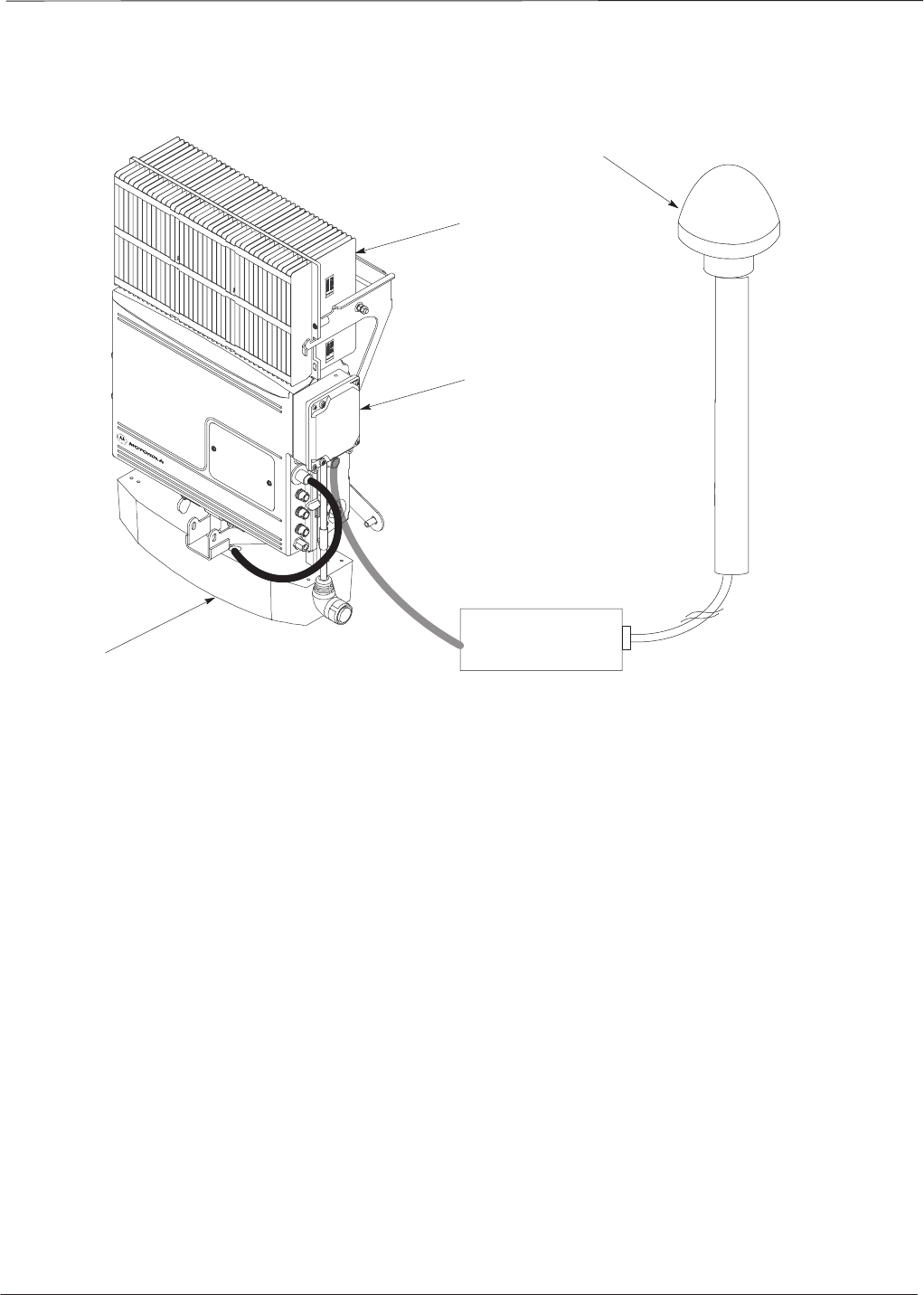
Field Replaceable Unit (FRU) Overview – continued
PRELIMINARY
SCt300 BTS Hardware Installation, ATP and FRU Procedures DEC 2000
9-2
Figure 9-1: FRU Items
UNIT
SHORT DURATION BATTERY
SITE I/O INTERFACE
RGPS HEAD
SITE I/O
JUNCTION
BOX
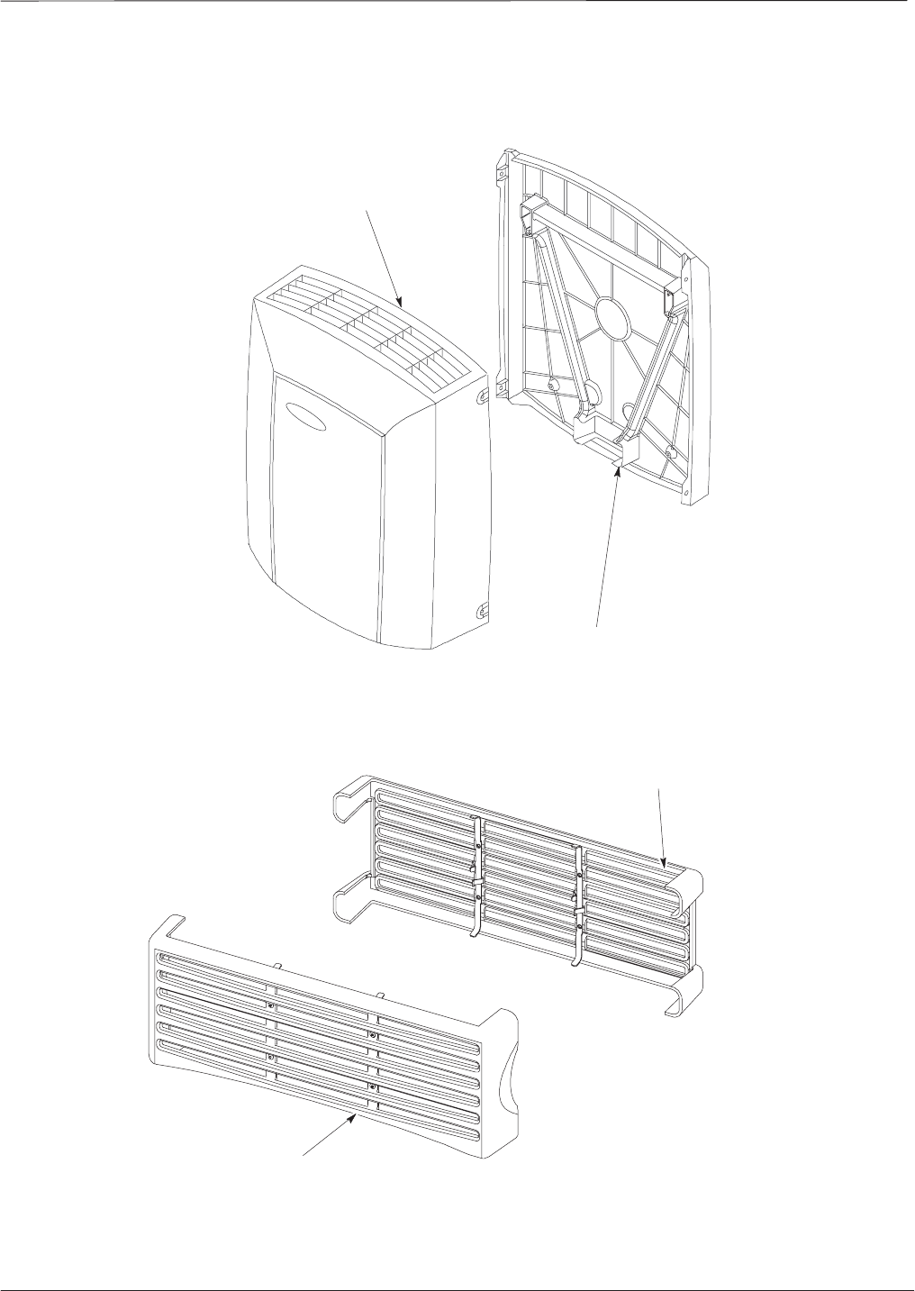
ATP Procedures – continued
DEC 2000 9-3
SCt300 BTS Hardware Installation, ATP and FRU Procedures
PRELIMINARY
Figure 9-2: Front and Back Solar Covers for MicroCell
FRONT COVER
BACK COVER
Figure 9-3: Front and Back Fin Covers for MicroCell and PicoCell (PicoCell shown)
BACK COVER
FRONT COVER 0149–O_IL.doc
Shut Down & Restoring BTS Signaling
PRELIMINARY
SCt300 BTS Hardware Installation, ATP and FRU Procedures DEC 2000
9-4
Overview
The FRU procedures require the shut down of BTS signalling functions.
Accessing the OMCR CLI
window
The commands to manipulate the BTS in the following replacement
procedure must be entered via UNO or OMCR (Operations and
Maintenance Center – Radio).
Should there be any issues which affect CLI operations or
the UNO/OMCR, this replacement procedure cannot be
performed.
IMPORTANT
*
Accessing the OMCR CLI window
The commands used in the following replacement procedure in Table 9-1
are entered at the OMCR.
Table 9-1: Login and Access Alarm Window Procedure
Step Action
1Login by entering the user name.
2Enter the password at the system prompt.
3Open an Alarm Manager window and an OMCR CLI window from the pull down menu using the
mouse button.
4Verify that the filter display is set to ALL. This is so that any alarms which may be encountered
while installing the hardware can be observed and rectified.
Shut Down Signaling Functions
Table 9-2 contains steps for shutting down the signaling functions for the
sector/site.
The BTS acts like a single sector and all sector commands
operate on the BTS carrier.
NOTE
9

Shut Down & Restore BTS Signaling – continued
DEC 2000 9-5
SCt300 BTS Hardware Installation, ATP and FRU Procedures
PRELIMINARY
The EDIT SECTOR REDIRECT command does NOT
affect calls in progress and will NOT move these calls to
another sector/carrier. The command only prevents future
calls from being originated on the targeted sector/carrier. If
active call processing is still taking place in the target
sector/carrier, it is advisable to wait for any active calls to
terminate prior to disabling the sector.
IMPORTANT
*
Table 9-2: Shut Down Signaling Functions
Step Action
1Open a CLI window. Refer to Table 9-1.
2Determine channel status of the MAWI prior to performing the following step by entering the
following command:
omc–000000>STATUS MAWI–<bts#>–<mawi#> ADD
This command will display the busy overhead channels as well as any busy traffic channels.
3* IMPORTANT
Record the values shown in the following system display response. These values will be used to
answer the prompts for the EDIT SECTOR REDIRECT command when restoring signaling
operations at the end of the replacement procedure.
View the status of the sector signaling redirect parameters for all carriers equipped for the sector
by entering the following command at the prompt:
000000>DISPLAY SECTOR <bt #> <t#>REDIRECT
omc–000000>DISPLAY SECTOR–<bts#>–<sector#> REDIRECT
Observe the following typical system display response (this example shows initial standard
values):
Access Overload Class Redirect Flags ROTATE
CARRIER ID RETURN 0 0 0 0 0 0 0 0 0 0 1 1 1 1 1 1 TIMER RECORD EXP IGNORE SYS
(bts–sector–carrier) IF FAIL 0 1 2 3 4 5 6 7 8 9 0 1 2 3 4 5 (SEC) TYPE SID CDMA ORDERING
–––––––––––––––––––– ––––––– – – – – – – – – – – – – – – – – ––––– –––– ––– –––– –––––––
CARRIER–1–1–1 N N N N N N N N N N N N N N N N N 4 1 0 N CUSTOM
. . . continued on next page
9

Shut Down & Restore BTS Signaling – continued
PRELIMINARY
SCt300 BTS Hardware Installation, ATP and FRU Procedures DEC 2000
9-6
Table 9-2: Shut Down Signaling Functions
Step Action
4NOTE
This step edits the redirect parameters so that the Global Service Redirect Message broadcast on
the paging channel redirects all subscribers away from the sector with the failed equipment and
onto a different system.
Enter the following command at the prompt:
omc–000000>EDIT SECTOR–<bts#>–<sector#> REDIRECT !
The system will prompt you to enter each command parameter value one at a time. Answer the
prompts in the following order:
<accolc0>
enter Y,
<accolc1>
enter Y,
...
<accolc15>
enter Y
(All Access Overload Classes must be set to yes to ensure that all subscribers are redirected.)
<returniffail>
, enter N
(Must be set to no to ensure that subscribers do not return if redirect is unsuccessful.)
<recordtype>
, enter 4
(A value of four redirects subscribers to a JTACS analog site )
(A
va
l
ue o
f
f
our re
di
rec
t
s su
b
scr
ib
ers
t
o a
JTACS
ana
l
og s
it
e.
)
<expectedsid>
, enter 13
(Use the Area ID the subscriber units should expect to find on the system they are being
redirected to. This example uses 13.)
<ignorecdma>
, enter Y
<sysordering>
, enter CUSTOM
(System ordering value does not matter because it is not used in JTACS systems.)
<rotatetimer>
, enter 4
(Call processing continuously rotates, circular right–shifts, the Y/N values of Access Overload
Class Redirect Flags 0 to 9. Values are shifted one flag at the end of the timer period; then timer
re–starts. Valid values are 0–255; 4 is default.)
The system will display the command that will be sent. Verify the command syntax.
omc–000000>Accept [yes/no]?
Enter Y to accept the command.
5View the status of the sector signaling redirect parameters to verify that the sector is ready for
maintenance.
omc–000000>DISPLAY SECTOR–<bts#>–<sector#> REDIRECT
Ensure that the values in the system display response match the values input in step 4 (see
example below).
Access Overload Class Redirect Flags ROTATE
CARRIER ID RETURN 0 0 0 0 0 0 0 0 0 0 1 1 1 1 1 1 TIMER RECORD EXP IGNORE SYS
(bts–sector–carrier) IF FAIL 0 1 2 3 4 5 6 7 8 9 0 1 2 3 4 5 (SEC) TYPE SID CDMA ORDERING
–––––––––––––––––––– ––––––– – – – – – – – – – – – – – – – – ––––– –––– –––– ––– ––––––––
CARRIER–1–1–1 N Y Y Y Y Y Y Y Y Y Y Y Y Y Y Y Y 4 4 13 Y CUSTOM
. . . continued on next page
9

Shut Down & Restore BTS Signaling – continued
DEC 2000 9-7
SCt300 BTS Hardware Installation, ATP and FRU Procedures
PRELIMINARY
Table 9-2: Shut Down Signaling Functions
Step Action
6View the existing congestion control parameters for all carriers equipped for the sector by entering
the following command at the prompt:
omc–000000>DISPLAY SECTOR–<bts#>–<sector#> CONGESTCONF
Observe the following typical system display response:
CARRIER NEWCALL REG AGG
(bts#–sector#–carrier#) SET ALARMFLAG ALARMFLAG ALARMFLAG ANALOGREDIRECT GLOBALREDIRECT
––––––––––––––––––––––– ––– ––––––––– –––––––––– –––––––––– –––––––––––––– ––––––––––––––
340–1–4 1 ENABLE ENABLE ENABLE DISABLE DISABLE
7NOTE
In this step, you will change the value of the Global Service Redirection Flag
(GLOBALREDIRECT) in the congestion control parameters so that the Global Service Redirect
Message is broadcast on the sector paging channel.
Enter the following command at the prompt:
omc–000000>EDIT SECTOR–<bts#>–<sector#> CONGESTCONF !
The system will prompt you to enter each control parameter value one at a time. Skip through the
prompts until you get to the following:
<
g
lobalredirect>
,
enter ENABLE
<globalredirect>
,
enter
ENABLE
(This will force the Global Service Redirect Message to be broadcast on the sector paging
channel.)
The system will display the values of the control parameters. Verify that only the
GLOBALREDIRECT value changed.
omc–000000>Accept [yes/no]?
Enter Y to accept the change.
Now the Global Service Redirection Message is sent over the sector paging channels. All
subscribers are redirected away from the sector and onto a different system. This effectively shuts
down the sector.
8Display the status of the MAWI at the BTS by entering the following command at the prompt:
omc–000000>DISPLAY BTS–<bts#> STATUS
Observe the following typical system response for the entry of: DISPLAY BTS – 340 STATUS
DEVSYNC
Config Calibration Calibration ISO RELATED
DEVICE CBSC STATUS Data Data Sync STATE
–––––––––––––––––– –––– –––––– –––– –––– ––––––– ––––––––––––
BTS–340 1 INS n/a n/a UNLOCKED UNLOCKED
BTSSPAN–340–1 1 INS n/a n/a n/a n/a
BTSLINK–340–1 1 INS n/a n/a n/a n/a
LPA–340–1 1 OOS_PARENT n/a n/a n/a n/a
MDM–340–1 1 PRECUT n/a n/a n/a n/a
MAWI–340–1 1 INS GOOD GOOD GOOD KEYED
. . . continued on next page
9

Shut Down & Restore BTS Signaling – continued
PRELIMINARY
SCt300 BTS Hardware Installation, ATP and FRU Procedures DEC 2000
9-8
Table 9-2: Shut Down Signaling Functions
Step Action
9Display the status of the MAWI at the BTS to verify the status of the MAWI (which CEs are
INS_IDLE or INS_BUSY) by entering the following command at the prompt:
omc–000000>STATUS MAWI–<bts#>–<mawi#> ADD
Observe the following typical system response:
MAWI–340–1 00–05–24 15:10:31 omcr5 MM–5 M000109.00046 045519/479457
INFO:42 ”Mawi Status Response”
TELSTATE=INS_ACTIVE PROCEDURE=NONE
PHYSTATE=INS_ACTIVE HDWR_TYPE=MAWI
DEVICE_ASSUMED=NONE CLOCK_SRC=REMOTE_GPS
LATITUDE=”+032:50:41.502” LONGITUDE=”–097:17:38.645”
ALTITUDE=”+0019865” NUM_SATELLITES=”8”
CF MMCONF MMSTATE MMSECTOR PHYCONF PHYSTATE PHYREASON PHYSECTOR
–– –––––– –––––––– –––––––– ––––––– –––––––– ––––––––– –––––––––
0 PCH_ACH INS_BUSY 1 PCH_ACH INS_BUSY NONE 1
1 SCH INS_BUSY 1 SCH INS_BUSY NONE 1
2 TCH INS_IDLE FLOAT TCH INS_IDLE NONE FLOAT
3 TCH INS_IDLE FLOAT TCH INS_IDLE NONE FLOAT
4 TCH INS_IDLE FLOAT TCH INS_IDLE NONE FLOAT
5 TCH INS_IDLE FLOAT TCH INS_IDLE NONE FLOAT
6 TCH INS_IDLE FLOAT TCH INS_IDLE NONE FLOAT
7 TCH INS_IDLE FLOAT TCH INS_IDLE NONE FLOAT
8 TCH INS_IDLE FLOAT TCH INS_IDLE NONE FLOAT
9 TCH INS_IDLE FLOAT TCH INS_IDLE NONE FLOAT
10 TCH INS_IDLE FLOAT TCH INS_IDLE NONE FLOAT
11 TCH INS_IDLE FLOAT TCH INS_IDLE NONE FLOAT
12 TCH INS_IDLE FLOAT TCH INS_IDLE NONE FLOAT
13 TCH INS_IDLE FLOAT TCH INS_IDLE NONE FLOAT
14 TCH INS_IDLE FLOAT TCH INS_IDLE NONE FLOAT
15 TCH INS_IDLE FLOAT TCH INS_IDLE NONE FLOAT
10 Disable the MAWI in the INS–IDLE or the INS–BUSY state (predetermine number of active calls
remaining to be terminated prematurely) by entering the following command at the prompt:
omc–000000>DISABLE MAWI–<bts#>–<mawi#> UNC
11 Disable the BTS where the replacement procedure will be performed by entering the following
command at the prompt:
omc–000000>DISABLE BTS–<bts#> UNC
9

Shut Down & Restore BTS Signaling – continued
DEC 2000 9-9
SCt300 BTS Hardware Installation, ATP and FRU Procedures
PRELIMINARY
Restore Signaling Operations
Follow the steps in Table 9-3 to restore signaling operations to the site.
Table 9-3: Restore Signaling Operations
Step Action
1Open a CLI window. Refer to Table 9-1.
2Enable the BTS by entering the following command at the prompt:
omc–000000>ENABLE BTS–<bts#> UNC
3Enable the MAWI by entering the following command at the prompt:
omc–000000>ENABLE MAWI–<bts#> UNC
4View the status of the sector signaling redirect parameters for all carriers equipped for the sector
by entering the following command at the prompt:
omc–000000>DISPLAY SECTOR–<bts#>–<sector#>
REDIRECT
Observe that the values in the system display response should match the values input in step 4 of
the shut down signaling functions table.
Access Overload Class Redirect Flags ROTATE
CARRIER ID RETURN 0 0 0 0 0 0 0 0 0 0 1 1 1 1 1 1 TIMER RECORD EXP IGNORE SYS
(bts–sector–carrier) IF FAIL 0 1 2 3 4 5 6 7 8 9 0 1 2 3 4 5 (SEC) TYPE SID CDMA ORDERING
–––––––––––––––––––– ––––––– – – – – – – – – – – – – – – – – ––––– –––– ––– –––– ––––––––
CARRIER–1–1–1 N Y Y Y Y Y Y Y Y Y Y Y Y Y Y Y Y 4 4 13 Y CUSTOM
. . . continued on next page
9

Shut Down & Restore BTS Signaling – continued
PRELIMINARY
SCt300 BTS Hardware Installation, ATP and FRU Procedures DEC 2000
9-10
Table 9-3: Restore Signaling Operations
Step Action
5* IMPORTANT
In this step, use the values recorded in step 3 of the shut down signaling functions table to answer
the prompts for the EDIT SECTOR REDIRECT command; except for record type enter 2.
NOTE
This step shows the entry of initial standard values which is consistent with the original example;
except record type must be 2. Your entries may be different.
Restore the values of all redirect parameters by entering the following command at the prompt:
omc–000000>EDIT SECTOR–<bts#>–<sector#>
REDIRECT !
The system will prompt you to enter each command parameter one at a time. Answer the prompts
in the following order (Note that the following specified values are consistent with the original
example. Yours may be different):
<accolc0>
Enter N,
<accolc1>
Enter N,
...
<accolc15>
enter N
<returniffail>
, enter N
<recordtype>
, enter 2
<expectedsid>
enter 0
<expecteds
i
d>
, en
t
er
0
<ignorecdma>
, enter N
<sysordering>
, enter CUSTOM
<rotatetimer>
, enter 4
The system will display the command that will be sent. Verify the command syntax.
omc–000000>Accept [yes/no]?
Enter Y to accept the command.
6View the status of the sector signaling redirect parameters to verify that the sector is ready for
maintenance.
omc–000000>DISPLAY SECTOR–<bts#>–<sector#> REDIRECT
Ensure that the values in the system display response match the values input by the operator in
step 5 (see example below).
Access Overload Class Redirect Flags ROTATE
CARRIER ID RETURN 0 0 0 0 0 0 0 0 0 0 1 1 1 1 1 1 TIMER RECORD EXP IGNORE SYS
(bts–sector–carrier) IF FAIL 0 1 2 3 4 5 6 7 8 9 0 1 2 3 4 5 (SEC) TYPE SID CDMA ORDERING
–––––––––––––––––––– ––––––– – – – – – – – – – – – – – – – – ––––– –––– ––– –––– ––––––––
CARRIER–1–1–1 N N N N N N N N N N N N N N N N N 4 2 0 N CUSTOM
. . . continued on next page
9

Shut Down & Restore BTS Signaling – continued
DEC 2000 9-11
SCt300 BTS Hardware Installation, ATP and FRU Procedures
PRELIMINARY
Table 9-3: Restore Signaling Operations
Step Action
7View the congestion control parameters for all carriers equipped for the sector by entering the
following command at the prompt:
omc–000000>DISPLAY SECTOR–<bts#>–<sector#> CONGESTCONF
Observe the following typical system display response:
CARRIER NEWCALL REG AGG
(bts#–sector#–carrier#) SET ALARMFLAG ALARMFLAG ALARMFLAG ANALOGREDIRECT GLOBALREDIRECT
––––––––––––––––––––––– ––– ––––––––– ––––––––– ––––––––– –––––––––––––– ––––––––––––––
340–1–4 1 ENABLE ENABLE ENABLE DISABLE ENABLE
8NOTE
In this step, you will change the value of the Global Service Redirection Flag
(GLOBALREDIRECT) in the congestion control parameters so that the Global Service Redirect
Message is only broadcast on the sector paging channel when there is traffic congestion in the
sector.
Enter the following command at the prompt:
omc–000000>EDIT SECTOR–<bts#>–<sector#> CONGESTCONF !
The system will prompt you to enter each control parameter value one at a time. Skip through the
prompts until you get to the following:
prompts
until
you
get
to
the
following:
<globalredirect>
, enter DISABLE
(This will revert the Global Service Redirect Message to congestion control.)
The system will display the values of the control parameters. Verify that only the
GLOBALREDIRECT value changed.
omc–000000>Accept [yes/no]?
Enter Y to accept the change.
Now the Global Service Redirection Message will only be sent over the sector paging channels
when there is traffic congestion in the sector.
9Display the status of the MAWI at the BTS by entering the following command at the prompt:
omc–000000>DISPLAY BTS–<bts#> STATUS
Observe the following typical system response:
DEVSYNC
Config Calibration Calibration ISO RELATED
DEVICE CBSC STATUS Data Data Sync STATE
–––––––––––––––––– –––– –––––– –––– –––– ––––––– ––––––––––––
BTS–340 1 INS n/a n/a UNLOCKED UNLOCKED
BTSSPAN–340–1 1 INS n/a n/a n/a n/a
BTSLINK–340–1 1 INS n/a n/a n/a n/a
LPA–340–1 1 OOS_PARENT n/a n/a n/a n/a
MDM–340–1 1 PRECUT n/a n/a n/a n/a
MAWI–340–1 1 INS GOOD GOOD GOOD KEYED
. . . continued on next page
9

Shut Down & Restore BTS Signaling – continued
PRELIMINARY
SCt300 BTS Hardware Installation, ATP and FRU Procedures DEC 2000
9-12
Table 9-3: Restore Signaling Operations
Step Action
10 Display the status of the MAWI in the BTS by entering the following command at the prompt:
omc–000000>STATUS MAWI–<bts#>–<mawi#> ADD
Observe the following typical system response for entry of: STATUS MAWI – 340 –1 ADD
MAWI–340–1 00–05–24 15:10:31 omcr5 MM–5 M000109.00046 045519/479457
INFO:42 ”Mawi Status Response”
TELSTATE=INS_ACTIVE PROCEDURE=NONE
PHYSTATE=INS_ACTIVE HDWR_TYPE=MAWI
DEVICE_ASSUMED=NONE CLOCK_SRC=REMOTE_GPS
LATITUDE=”+032:50:41.502” LONGITUDE=”–097:17:38.645”
ALTITUDE=”+0019865” NUM_SATELLITES=”8”
CF MMCONF MMSTATE MMSECTOR PHYCONF PHYSTATE PHYREASON PHYSECTOR
–– –––––– –––––––– –––––––– ––––––– –––––––– ––––––––– –––––––––
0 PCH_ACH INS_BUSY 1 PCH_ACH INS_BUSY NONE 1
1 SCH INS_BUSY 1 SCH INS_BUSY NONE 1
2 TCH INS_IDLE FLOAT TCH INS_IDLE NONE FLOAT
3 TCH INS_IDLE FLOAT TCH INS_IDLE NONE FLOAT
4 TCH INS_IDLE FLOAT TCH INS_IDLE NONE FLOAT
5 TCH INS_IDLE FLOAT TCH INS_IDLE NONE FLOAT
6 TCH INS_IDLE FLOAT TCH INS_IDLE NONE FLOAT
7 TCH INS_IDLE FLOAT TCH INS_IDLE NONE FLOAT
8 TCH INS_IDLE FLOAT TCH INS_IDLE NONE FLOAT
9 TCH INS_IDLE FLOAT TCH INS_IDLE NONE FLOAT
10 TCH INS_IDLE FLOAT TCH INS_IDLE NONE FLOAT
11 TCH INS_IDLE FLOAT TCH INS_IDLE NONE FLOAT
12 TCH INS_IDLE FLOAT TCH INS_IDLE NONE FLOAT
13 TCH INS_IDLE FLOAT TCH INS_IDLE NONE FLOAT
14 TCH INS_IDLE FLOAT TCH INS_IDLE NONE FLOAT
15 TCH INS_IDLE FLOAT TCH INS_IDLE NONE FLOAT
9

Site I/O Junction Box Replacement Procedure
DEC 2000 9-13
SCt300 BTS Hardware Installation, ATP and FRU Procedures
PRELIMINARY
Objective
The objective of this procedure is to replace the Site I/O junction box.
System Impact/Considerations
The removal of the failed Site I/O junction box will require system
downtime. The BTS cannot report alarms without the Site I/O junction
box. The other system level alarms are too numerous and outside the
scope of this document.
Required Tools and Materials
The following tools are required to remove the solar cover and install the
new Site I/O junction box.
Tools
STorque driver wrench, 1/4–in. hex female drive, 0–10 N–M
ST20 Torx tamper bit
ST30 Torx tamper bit
Replacement units
One Site I/O junction box is required – Kit T396AA
Replacement Procedure
Before you begin
Before you begin, enter the following information into the following
replacement list table.
Table 9-4: Item Number Replacement List
Item Number
BTS number
Failed Site I/O Junction Box
number
9

Site I/O Junction Box Replacement Procedure – continued
PRELIMINARY
SCt300 BTS Hardware Installation, ATP and FRU Procedures DEC 2000
9-14
Remove the failed site I/O junction box
Follow the steps in Table 9-5 to remove the failed Site I/O junction box.
Table 9-5: Remove the Failed Site I/O Junction Box
Step Action
1Place the BTS out of service using the “Shut Down Signaling Functions” procedure shown in
Table 9-2.
2Using a T20 Torx tamper bit, remove the Solar Cover if one is present and locate the failed Site
I/O junction box.
3If DC power is being supplied to the unit or if the battery backup is present, open (pull) the DC
power breaker. The white collar on the breaker is visible when the breaker is opened.
4If AC power is being supplied to the unit, open (pull) the AC power breaker. The white collar on
the breaker is visible when the breaker is open.
5Disconnect the unit ground cable from the Site I/O junction box.
6Using a T30 Torx tamper bit, remove the two tamper resistant captive screws to disconnect the
Site I/O junction box from the unit. See Figure 9-4.
7If your BTS is equipped with the customer–supplied Site I/O interface, then proceed to step 8. If
your BTS is equipped with the optional Primary Surge Suppressor, then proceed to step 9.
8Disconnect the Site I/O cable from the Deutsch connector on the Site I/O cable. Location of Site
I/O interface is site– dependent.
9Disconnect the Site I/O cable from the Primary Surge Suppressor.
Install the replacement Site I/O junction box
Follow the steps in Table 9-6 to install the replacement Site I/O junction
box.
Table 9-6: Install the Replacement Site I/O Junction Box
Step Action
1Reconnect the Site I/O cable according to the “Site I/O, Span Line, RGPS and Modem Cabling”
procedure in Chapter 4.
2Install the replacement Site I/O junction box according to the “Mounting the Site I/O Junction
Box to the Unit” procedure in Chapter 5.
3Attach the ground cable from the mounting bracket to the Site I/O junction box.
4If AC power is being supplied to the unit, close (push) the AC power breaker. The white collar on
the breaker is not visible when the breaker is closed.
5If DC power is being supplied to the unit or if battery backup is present, close (push) the DC
power breaker. The white collar on the breaker is not visible when the breaker is closed.
6Install the Solar Cover if one is present according to the “Mounting Solar Cover and Powering on
Unit” procedure in Chapter 5.
7Place the BTS back in service using the “Restore Signaling Operations” procedure in Table 9-3.
9
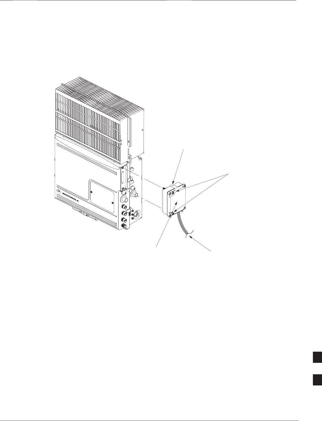
Site I/O Junction Box Replacement Procedure – continued
DEC 2000 9-15
SCt300 BTS Hardware Installation, ATP and FRU Procedures
PRELIMINARY
Site I/O Junction Box Location
Diagram
Figure 9-4: Site I/O Junction Box Replacement
REMOVE TWO M6
CAPTIVE SCREWS
SITE I/O
JUNCTION BOX DISCONNECT SITE I/O
CABLE FROM SITE I/O
INTERFACE
DISCONNECT GROUND
9

Short Duration Battery Replacement Procedures
PRELIMINARY
SCt300 BTS Hardware Installation, ATP and FRU Procedures DEC 2000
9-16
Objective
The objective of this procedure is to replace the short duration battery.
Required Tools and Materials
The following tools are required to remove the solar cover and install the
new battery.
Tools
Attaching the battery to the unit requires:
ST20 Torx tamper bit, 1/4–in. hex
ST30 Torx tamper bit, 1/4–in. hex
STorque driver wrench, 1/4–in. hex female drive, 0–10 N–M
STwo (2) Screws M6x19 (Motorola Part Number 0387541C03)
Replacement units
One Battery – Kit T392AA is necessary for this procedure.
Replacement Procedure
Before you begin
Before you begin, enter the following information into the following
replacement list table.
Table 9-7: Item Number Replacement List
Item Number
BTS number
Failed Battery number
9

Short Duration Battery Replacement Procedure – continued
DEC 2000 9-17
SCt300 BTS Hardware Installation, ATP and FRU Procedures
PRELIMINARY
Remove the failed battery
Follow the steps in Table 9-8 to remove the failed battery. Refer to
Figure 9-5.
The short duration battery is designed to be replaced with
the DC breaker closed (pushed). If the DC breaker is
opened (pulled) during this procedure, the BTS must be
taken off–line and restarted to ensure proper battery fault
management.
NOTE
Table 9-8: Remove the Failed Short Duration Battery
Step Action
1Turn the DC Power Breaker off.
2Use a T20 Torx tamper bit to remove the Solar Cover (if one is present) and locate the battery.
3Turn the connector on the short duration battery cable counterclockwise to disconnect the cable
from the unit. See Figure 9-5. An alarm will be generated.
4Using a T30 Torx tamper bit remove the two screws that are holding the battery to the unit. See
Figure 9-5.
Install the replacement battery
Follow the steps in Table 9-8 to install the replacement short duration
battery. Refer to Figure 9-5.
Table 9-9: Install the Replacement Short Duration Battery
Step Action
1Install the replacement battery according to the “Attaching the Battery to the Unit” installation
procedure in Chapter 5.
2Re–connect the short–duration battery cable to DC input connector. See Figure 9-5. The alarm
will clear.
3Re–install the Solar Cover if one is present.
9
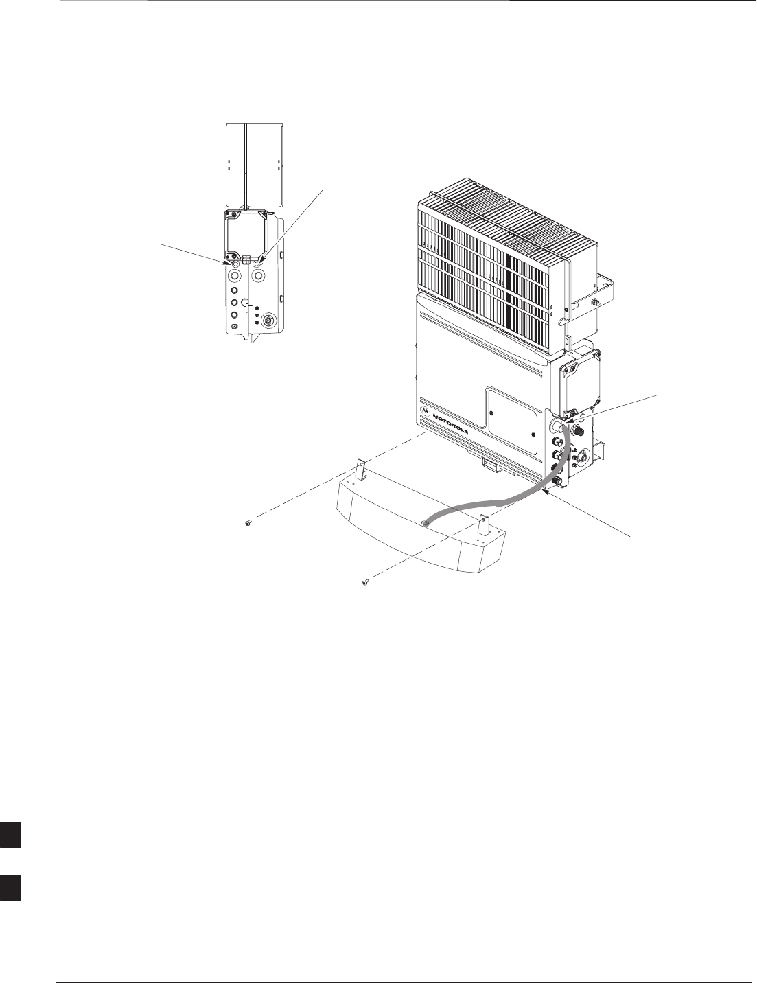
Short Duration Battery Replacement Procedure – continued
PRELIMINARY
SCt300 BTS Hardware Installation, ATP and FRU Procedures DEC 2000
9-18
Figure 9-5: Battery Replacement
REMOVE TWO SCREWS HOLDING
BATTERY TO THE UNIT
CABLE IS PART OF
THE BATTERY
ASSEMBLY
TURN
COUNTERCLOCKWISE
TO REMOVE CABLE
DC POWER BREAKER
AC POWER BREAKER
9

Remote GPS Replacement Procedures
DEC 2000 9-19
SCt300 BTS Hardware Installation, ATP and FRU Procedures
PRELIMINARY
Objective
The objective of this procedure is to replace the RGPS head.
Required Tools and Materials
Replacement units
One RGPS head with cable attached (Motorola Kit T472AP) is required
to do this procedure.
Replacement Procedure
Before you begin
Before you begin, enter the following information into the following
replacement list table.
Table 9-10: Item Number Replacement List
Item Number
BTS number
Failed RGPS head number
Remove the failed RGPS head
Follow the steps in Table 9-11 to remove the failed RGPS head. Refer to
Figure 9-6.
Table 9-11: Remove the Failed RGPS Head
Step Action
NOTE
To prevent twisting of cables, do not unscrew or screw the RGPS head while holding the
pipe/conduit.
1Loosen the pipe/conduit mounting hardware until the pipe/conduit is free to be unscrewed from
the RGPS head.
2Grasp the RGPS head with one hand and the pipe/conduit with the other hand.
Unscrew the pipe/conduit from the head and separate the head from the pipe/conduit.
Grasp the cable just below the head and pull about 16 inches of cable out of the pipe/conduit until
the mating cable connectors are exposed.
3Separate the mating cable connectors to disconnect the RGPS head from the RGPS cable. 9
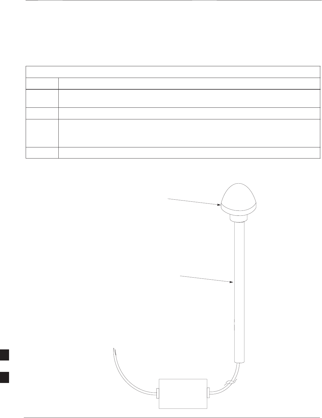
Remote GPS Replacement Procedure – continued
PRELIMINARY
SCt300 BTS Hardware Installation, ATP and FRU Procedures DEC 2000
9-20
Install the replacement RGPS head
Follow the steps in Table 9-12 to install the replacement RGPS head.
Refer to Figure 9-6.
Table 9-12: Install the Replacement RGPS Head
Step Action
1Connect the cable connector of the replacement RGPS head to the RGPS cable connector. Secure
the connection by tightening the spinning connector flange.
2Feed the cable slack into the RGPS head end of the mounting pipe/conduit.
3Grasp the RGPS head with one hand and the pipe/conduit with the other hand.
Be careful not to cross–thread the fitting on the RGPS head, screw the pipe/conduit into the head.
Hand tighten only!
4Tighten the pipe/conduit mounting hardware until the pipe/conduit is securely mounted.
Figure 9-6: RGPS Head Replacement
SITE I/O INTERFACE
UNSCREW PIPE, PULL CABLE THROUGH AND
DISCONNECT CABLE CONNECTOR
CABLE CONNECTOR LOCATED
INSIDE PIPE
9

Full Unit Replacement Procedures
DEC 2000 9-21
SCt300 BTS Hardware Installation, ATP and FRU Procedures
PRELIMINARY
Objective
The objective of this procedure is to replace a Microcell or Picocell unit.
See Figure 9-7.
System Impact/Considerations
The removal of the failed unit will require system downtime.
Required Tools and Materials
The following tools and materials are required to do this procedure:
Tools
The following tools are required to do this procedure:
STorque driver wrench, 1/4–in. hex female drive, 0–10 N–M
ST20 TORX Tamper Bit, 1/4–in. hex
ST30 TORX Tamper Bit, 1/4–in. hex
S13 mm torque wrench set to 5.0 N–M
S5/16 breakaway torque wrench 9–in. lb.
S13/16 breakaway torque wrench 38–in. lb
SKey for lock
SHandles for unit (optional)
Replacement units
One Microcell or Picocell unit is required to do this procedure.
Replacement Procedure
Before you begin
Before you begin, enter the following information into the following
replacement list table.
Table 9-13: Item Number Replacement List
Item Description
BTS Number
Failed Unit Number
Remove the failed unit
Follow the steps in Table 9-14 to remove the failed unit.
Table 9-14: Remove the Failed Unit
Step Action
1Place the BTS out of service. Refer to the “Shut Down Signaling Functions” procedure in
Table 9-2.
2If necessary, use a T20 TORX Tamper bit to remove the Solar Cover.
. . . continued on next page
9

Full Unit Replacement Procedures – continued
PRELIMINARY
SCt300 BTS Hardware Installation, ATP and FRU Procedures DEC 2000
9-22
Table 9-14: Remove the Failed Unit
Step Action
3If DC power is being supplied to the unit or if battery backup is present, open (pull) the DC power
breaker. The white collar on the breaker is visible when the breaker is opened.
4If AC power is being supplied to the unit, open (pull) the AC power breaker. The white collar on
the breaker is visible when the breaker is opened.
5Turn the power off at the main power source (AC and/or DC).
6Use a T30 TORX tamper bit to remove the two tamper–resistant screws that hold the Site I/O
junction box (or environmental cover) to the BTS. Refer to Figure 9-4 in the “Site I/O Junction
Box Replacement” procedure.
7Disconnect the AC input cable from the unit. Refer to Figure 9-7.
8Disconnect the DC input cable from the unit. Refer to Figure 9-7.
9Disconnect the antenna cable(s) from the unit. Refer to Figure 9-7.
10 Disconnect the MIB cables from the unit (if equipped). Refer to Figure 9-7.
11 Disconnect the SU cables from the unit (if equipped). Refer to Figure 9-7.
12 Remove the two mounting screws that hold the short duration battery (if present) to the unit.
Refer to NO TAG in the “Short Duration Battery Replacement Procedures” procedure and
Figure 9-7.
13 Attach the installation handles to the unit. Refer to the “Attaching Installation Handles to the
Unit” procedure in Chapter 6.
14 Use a T30 Tamper bit to remove the two screws that hold the unit to the mounting bracket.
15 Remove the pin or lock (if equipped) from the unit.
16 Remove the unit from the mounting bracket.
9

Full Unit Replacement Procedures – continued
DEC 2000 9-23
SCt300 BTS Hardware Installation, ATP and FRU Procedures
PRELIMINARY
Install the replacement unit
Follow the steps in Table 9-15 to install the replacement unit.
Table 9-15: Install the New Unit
Step Action
1Attach the installation handles to the replacement unit. Refer to the “Attaching Installation
Handles to Unit” procedure in Chapter 6.
2Mount the replacement unit to the bracket. Refer to the “Attaching Unit to the Mounting
Bracket” procedure in Chapter 6.
3Once the replacement unit has been secured to the mounting bracket, remove the installation
handles (reverse the installation order of the “Attaching Installation Handles to the Unit”
procedure in Chapter 6).
4Attach the Site I/O junction box or environmental cover to the unit. Refer to the “Attaching the
Site I/O Junction Box to the Unit” procedure in Chapter 6 and Figure 9-4.
5Attach the short duration battery (if present) to the unit. Refer to NO TAG in the “Short Duration
Battery Replacement Procedure” and Figure 9-7.
6Connect the AC input cable. Refer to the “AC Power Cabling” procedure in Chapter 6.
7Connect the DC input cable. Refer to the “DC Power Cabling” procedure in Chapter 6.
8Connect the antenna cable(s). Refer to the “Antenna Cabling” procedure in Chapter 6.
9Connect the MIB cables (if equipped). Refer to the “MIB Cabling” procedure in Chapter 6.
10 Connect the SU cables (if equipped). Refer to the “SU Cabling” procedure in Chapter 6.
11 Turn power on at the main power source (AC and/or DC).
12 If AC power is being supplied to the unit, close (push) the AC power breaker. The white collar on
the breaker is not visible when the breaker is closed.
13 If DC power is being supplied to the unit or if battery backup is present, close (push) the DC
power breaker. The white collar is not visible when the breaker is closed.
14 Perform the ATP, if necessary. Refer to the ATP procedures in Chapter 7.
15 Install the Solar Covers (if necessary).
16 Place the BTS back in service using the “Restore Signaling Operations” procedure in Table 9-3.
9
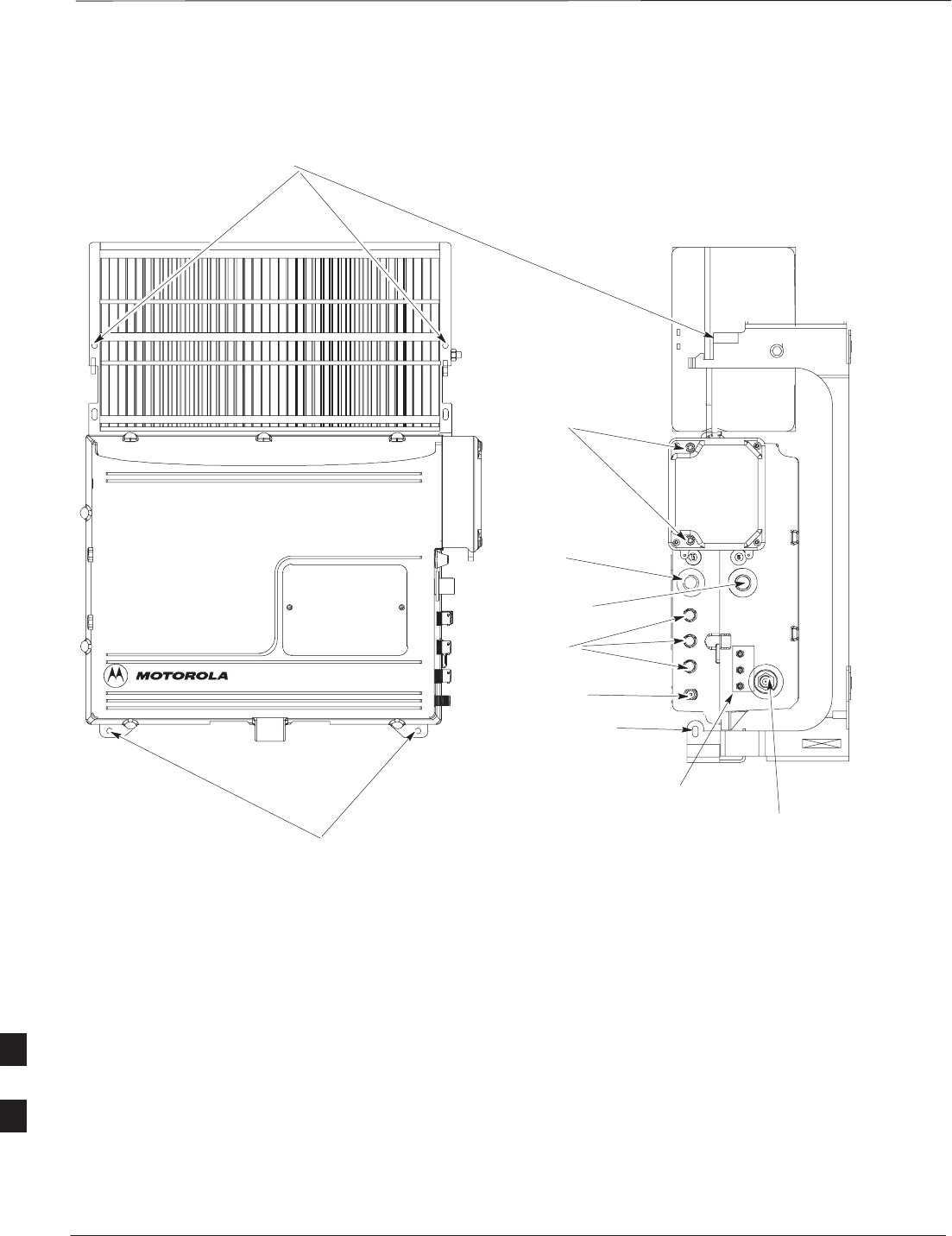
Full Unit Replacement Procedures – continued
PRELIMINARY
SCt300 BTS Hardware Installation, ATP and FRU Procedures DEC 2000
9-24
REMOVE SCREWS USED TO
HOLD UNIT ON BRACKET
REMOVE SCREWS TO
REMOVE SITE I/O JUNCTION
BOX OR ENVIRONMENTAL
COVER (IF EQUIPPED)
DC INPUT CABLE
AC INPUT CABLE
REMOVE PIN
ANTENNA A
REMOVE SCREWS TO REMOVE SHORT DURATION BATTERY
SEE FIGURE 7–3 FOR BATTERY REPLACEMENT
NOTE: REMOVE THE SITE I/O JUNCTION BOX (OR ENVIRONMENTAL COVER) AND
BATTERY FROM THE FAILED UNIT AND RE–MOUNT THEM ON THE REPLACEMENT UNIT
ANTENNA B
(MICROCELL ONLY)
Figure 9-7: Unit Replacement (MicroCell shown)
MIB CABLES
(OPTIONAL)
SU CABLES
(OPTIONAL)
9

Full Unit Replacement Procedures – continued
DEC 2000 9-25
SCt300 BTS Hardware Installation, ATP and FRU Procedures
PRELIMINARY
Notes
9

DEC 2000 SCt300 BTS Hardware Installation, ATP and FRU Procedures
PRELIMINARY
Appendix A: Outdoor Grounding Guidelines Overview
Appendix Content
Outdoor Grounding Guidelines Summary A-1. . . . . . . . . . . . . . . . . . . . . . . . . . . . .
General A-1. . . . . . . . . . . . . . . . . . . . . . . . . . . . . . . . . . . . . . . . . . . . . . . . . .
Chassis isolation A-1. . . . . . . . . . . . . . . . . . . . . . . . . . . . . . . . . . . . . . . . . .
Master ground plate A-1. . . . . . . . . . . . . . . . . . . . . . . . . . . . . . . . . . . . . . . .
Main AC power A-1. . . . . . . . . . . . . . . . . . . . . . . . . . . . . . . . . . . . . . . . . . .
Antenna A-1. . . . . . . . . . . . . . . . . . . . . . . . . . . . . . . . . . . . . . . . . . . . . . . . .
Chassis A-2. . . . . . . . . . . . . . . . . . . . . . . . . . . . . . . . . . . . . . . . . . . . . . . . . .
T1 span lines A-2. . . . . . . . . . . . . . . . . . . . . . . . . . . . . . . . . . . . . . . . . . . . .
Modem A-2. . . . . . . . . . . . . . . . . . . . . . . . . . . . . . . . . . . . . . . . . . . . . . . . . .
Customer I/O A-2. . . . . . . . . . . . . . . . . . . . . . . . . . . . . . . . . . . . . . . . . . . . .
A

Table of Contents – continued
PRELIMINARY
SCt300 BTS Hardware Installation, ATP and FRU Procedures DEC 2000
Notes
A

Outdoor Grounding Guidelines Summary
DEC 2000 A-1
SCt300 BTS Hardware Installation, ATP and FRU Procedures
PRELIMINARY
General
This is a summary of the outdoor grounding guidelines. Outdoor
installations should be based on this summary and site specific
documentation. Motorola publication 68P81150E62 should also be
followed to ground an antenna tower.
This guideline assumes that auxiliary equipment is co–located at the
installation site. All of the equipment referenced may not be present at
every site.
Because outdoor MicroCell/PicoCell installations will involve a variety
of methods, this information is not meant to represent actual physical
layout. It is meant to act as an aid to understanding an effective ground
system.
Chassis Isolation
Regardless of the type of installation (wall, frame, pole), the grounding
plan must have a single point ground to prevent surge/transient currents
from passing through the BTS and auxiliary equipment. The BTS
includes insulation hardware to insure that the chassis will be grounded
by the intended ground path and not through the mounting structure
(frame, pole, or wall).
Master Ground Plate
The Master Ground Plate (MGP) is the key to the outdoor grounding
scheme. The MGP is the single grounding point for all BTS input and
output and provides a uniform ground potential through out the site.
Although the MGP may be implemented differently at each installation,
it must be a plate that is big enough to attach to all the lightning arrestors
and have a ground stud.
The MGP ground stud is the only connection to earth ground for the
BTS hardware.
Main AC Power
The AC power input is single–phase and connects to the BTS by a three
conductor cable. The cable is insulated and connects to the BTS on one
end and the AC source on the other end. The AC power source should
be ground referenced to the MGP at a point closest to the access point.
The line and neutral conductors must be protected by lightning arrestors.
The lightning arrestors connect to the MGP at the same point as the AC
ground reference.
If an external circuit breaker or an uninterruptible power supply are used,
install them between the AC power lightning arrestor and the BTS.
Antenna
Coaxial cables are used to connect to the antenna(s). The ground
conductor (shield) of the coaxial cable must be ground referenced to the
A

Outdoor Grounding Guidelines Summary – continued
PRELIMINARY
SCt300 BTS Hardware Installation, ATP and FRU Procedures DEC 2000
A-2
MGP at the antenna access point. The signal (center) conductor must be
protected by a lightning arrestor. The lightning arrestor connects to the
MGP at the same point as the ground conductor (shield) of the antenna
cable.
Chassis
The ground stud of the BTS chassis connects to the MGP.
T1 Span Lines
The BTS can connect to two T1 span lines. For many applications the
T1 cable is derived from an optical fiber interconnect. For cases where
the optical interconnect is non–metallic, no special grounding is needed.
If the optical fiber is encased in a metallic sheath, the sheath must be
grounded to the MGP. If the span lines are metallic, the conductors must
be protected by lightning arrestors which connect to the MGP at a point
closest to the demarcation point.
Modem
A single tip and ring pair is used for a dial–up modem connection. The
tip and ring pair must be protected by a lightning arrestor which
connects to the MGP at a point closest to the demarcation point.
Customer I/O
The BTS provides eight customer defined inputs. These connections are
internal to the cell site and do not require special grounding unless they
originate from an area not protected by the MGP.
Example: Signal light in tower configuration
A