Nokia Solutions and Networks T6BV1 GSM 1900 Base Transceiver Station User Manual 68P02902W06 B UK CI
Nokia Solutions and Networks GSM 1900 Base Transceiver Station 68P02902W06 B UK CI
Contents
- 1. Indoor Service Manual
- 2. Outdoor service manual
Indoor Service Manual
For:cll
Printed on:Wed, Sep 26, 2001 04:43:05
From book:68P02902W06-B-UK-CI
Document:cat_tabs
Last saved on:Wed, Sep 26, 2001 04:42:50
Document:newcover
Last saved on:Wed, Sep 26, 2001 04:42:45
Document:cover (back)
Last saved on:Wed, Sep 26, 2001 04:42:44
Document:newspine1
Last saved on:Wed, Sep 26, 2001 04:42:45
Document:spine1 (back)
Last saved on:Wed, Sep 26, 2001 04:42:45
Document:insidecover-legal
Last saved on:Wed, Sep 26, 2001 04:42:51
Document:toc
Last saved on:Wed, Sep 26, 2001 04:42:51
Document:Introduction
Last saved on:Wed, Sep 26, 2001 04:42:50
Document:Warnings and Cautions
Last saved on:Wed, Sep 26, 2001 04:42:50
Document:Manual information
Last saved on:Wed, Sep 26, 2001 04:42:50
Document:tabs 1 to 5
Last saved on:Wed, Sep 26, 2001 04:42:47
( ...)

CATEGORY 423
INSTALLATION AND
CONFIGURATION
CATEGORY 523
MAINTENANCE
INFORMATION
CATEGORY 623
PARTS INFORMATION INDEXCATEGORY 323
TECHNICAL DESCRIPTION


Including:
68P02902W07-B
68P02902W08-B
68P02902W09-B
68P02902W10-B
Horizon
macro
indoor
CONTROLLED INTRODUCTION
Service Manual
GSM-205-020
68P02902W06-B


CONTROLLED
INTRODUCTION
68P02902W07-B
68P02902W08-B
68P02902W09-B
68P02902W10-B
68P02902W06-B
Service Manual
Horizon
macro
indoor
GSM-205-020
CONTROLLED INTRODUCTION
Horizon
macro
indoor
Including:
Positin mark for TED spine
Service
Manual


31st Oct 01
Service Manual: Horizon
macro
indoor
68P02902W06-B
CONTROLLED INTRODUCTION
i
GSM-205-020
Service Manual
Horizon
macro
indoor
E Motorola 1999-2001
All Rights Reserved
Printed in the U.K.

GSM-205-020
31st Oct 01
ii
Service Manual: Horizon
macro
indoor
CONTROLLED INTRODUCTION
68P02902W06-B
Copyrights, notices and trademarks
Copyrights
The Motorola products described in this document may include copyrighted Motorola computer
programs stored in semiconductor memories or other media. Laws in the United States and other
countries preserve for Motorola certain exclusive rights for copyright computer programs, including the
exclusive right to copy or reproduce in any form the copyright computer program. Accordingly, any
copyright Motorola computer programs contained in the Motorola products described in this document
may not be copied or reproduced in any manner without the express written permission of Motorola.
Furthermore, the purchase of Motorola products shall not be deemed to grant either directly or by
implication, estoppel or otherwise, any license under the copyrights, patents or patent applications of
Motorola, except for the rights that arise by operation of law in the sale of a product.
Restrictions
The software described in this document is the property of Motorola. It is furnished under a license
agreement and may be used and/or disclosed only in accordance with the terms of the agreement.
Software and documentation are copyright materials. Making unauthorized copies is prohibited by
law. No part of the software or documentation may be reproduced, transmitted, transcribed, stored
in a retrieval system, or translated into any language or computer language, in any form or by any
means, without prior written permission of Motorola.
Accuracy
While reasonable efforts have been made to assure the accuracy of this document, Motorola
assumes no liability resulting from any inaccuracies or omissions in this document, or from the use
of the information obtained herein. Motorola reserves the right to make changes to any products
described herein to improve reliability, function, or design, and reserves the right to revise this
document and to make changes from time to time in content hereof with no obligation to notify any
person of revisions or changes. Motorola does not assume any liability arising out of the application
or use of any product or circuit described herein; neither does it convey license under its patent
rights of others.
Trademarks
and
MOTOROLA
are registered trademarks of Motorola Inc.
Aspira, Intelligence Everywhere, M-Cell and Taskfinder are trademarks of Motorola Inc.
All other brands and corporate names are trademarks of their respective owners.

GSM-205-020
31st Oct 01
Service Manual: Horizon
macro
indoor
68P02902W06-B
CONTROLLED INTRODUCTION
iii
Issue status of this manual 1. . . . . . . . . . . . . . . . . . . . . . . . . . . . . . . . . . . . . . . . . . . .
General information 2. . . . . . . . . . . . . . . . . . . . . . . . . . . . . . . . . . . . . . . . . . . . . . . . . .
First aid in case of electric shock 4. . . . . . . . . . . . . . . . . . . . . . . . . . . . . . . . . . . . . . .
Reporting safety issues 5. . . . . . . . . . . . . . . . . . . . . . . . . . . . . . . . . . . . . . . . . . . . . . .
Warnings and cautions 6. . . . . . . . . . . . . . . . . . . . . . . . . . . . . . . . . . . . . . . . . . . . . . .
General warnings 7. . . . . . . . . . . . . . . . . . . . . . . . . . . . . . . . . . . . . . . . . . . . . . . . . . . .
General cautions 9. . . . . . . . . . . . . . . . . . . . . . . . . . . . . . . . . . . . . . . . . . . . . . . . . . . . .
Devices sensitive to static 10. . . . . . . . . . . . . . . . . . . . . . . . . . . . . . . . . . . . . . . . . . . . .
Motorola GSM manual set 11. . . . . . . . . . . . . . . . . . . . . . . . . . . . . . . . . . . . . . . . . . . .
GMR amendment 14. . . . . . . . . . . . . . . . . . . . . . . . . . . . . . . . . . . . . . . . . . . . . . . . . . . .
GMR amendment record 15. . . . . . . . . . . . . . . . . . . . . . . . . . . . . . . . . . . . . . . . . . . . . .
Category 323
Technical Description (Tech.) i. . . . . . . . . . . . . . . . . . . . . . . . . . . . . . . . . . . . . . .
Chapter 1
Overview and specifications i. . . . . . . . . . . . . . . . . . . . . . . . . . . . . . . . . . .
Equipment introduction and manual definition Tech. 1–1. . . . . . . . . . . . . . . . . . . . . . . . . . .
Overview of Horizonmacro indoor Tech. 1–1. . . . . . . . . . . . . . . . . . . . . . . . . . . . . . . . .
Names and acronyms for main cabinet equipment Tech. 1–2. . . . . . . . . . . . . . . . . .
Cabinet inside view Tech. 1–3. . . . . . . . . . . . . . . . . . . . . . . . . . . . . . . . . . . . . . . . . . . . .
Configuration information Tech. 1–4. . . . . . . . . . . . . . . . . . . . . . . . . . . . . . . . . . . . . . . .
Finding information in this manual Tech. 1–4. . . . . . . . . . . . . . . . . . . . . . . . . . . . . . . . .
Stacking capability and cabinet view Tech. 1–5. . . . . . . . . . . . . . . . . . . . . . . . . . . . . .
Functional diagram of Horizonmacro Tech. 1–6. . . . . . . . . . . . . . . . . . . . . . . . . . . . . .
M-Cell6 comparison with Horizonmacro Tech. 1–7. . . . . . . . . . . . . . . . . . . . . . . . . . . . . . . . .
Comparison overview Tech. 1–7. . . . . . . . . . . . . . . . . . . . . . . . . . . . . . . . . . . . . . . . . . .
Horizonmacro and M-Cell6 compatibility Tech. 1–7. . . . . . . . . . . . . . . . . . . . . . . . . . .
Comparison of Horizonmacro and M-Cell6 connections and modules Tech. 1–8. .
Specifications Tech. 1–9. . . . . . . . . . . . . . . . . . . . . . . . . . . . . . . . . . . . . . . . . . . . . . . . . . . . . . .
Overview of specifications Tech. 1–9. . . . . . . . . . . . . . . . . . . . . . . . . . . . . . . . . . . . . . .
Software requirements Tech. 1–9. . . . . . . . . . . . . . . . . . . . . . . . . . . . . . . . . . . . . . . . . .
Approval and safety Tech. 1–9. . . . . . . . . . . . . . . . . . . . . . . . . . . . . . . . . . . . . . . . . . . . .
Environmental limits Tech. 1–9. . . . . . . . . . . . . . . . . . . . . . . . . . . . . . . . . . . . . . . . . . . . .
Power requirements Tech. 1–10. . . . . . . . . . . . . . . . . . . . . . . . . . . . . . . . . . . . . . . . . . . . .
RF power output Tech. 1–11. . . . . . . . . . . . . . . . . . . . . . . . . . . . . . . . . . . . . . . . . . . . . . . .
Sensitivity Tech. 1–12. . . . . . . . . . . . . . . . . . . . . . . . . . . . . . . . . . . . . . . . . . . . . . . . . . . . . .
Battery backup Tech. 1–12. . . . . . . . . . . . . . . . . . . . . . . . . . . . . . . . . . . . . . . . . . . . . . . . .
BSC connectivity options Tech. 1–12. . . . . . . . . . . . . . . . . . . . . . . . . . . . . . . . . . . . . . . .
Indoor cabinet dimensions Tech. 1–12. . . . . . . . . . . . . . . . . . . . . . . . . . . . . . . . . . . . . . .
Weights Tech. 1–13. . . . . . . . . . . . . . . . . . . . . . . . . . . . . . . . . . . . . . . . . . . . . . . . . . . . . . . .
Torque values Tech. 1–13. . . . . . . . . . . . . . . . . . . . . . . . . . . . . . . . . . . . . . . . . . . . . . . . . .
Frequency capability Tech. 1–14. . . . . . . . . . . . . . . . . . . . . . . . . . . . . . . . . . . . . . . . . . . .
Structural considerations Tech. 1–16. . . . . . . . . . . . . . . . . . . . . . . . . . . . . . . . . . . . . . . . .
Layout plan Tech. 1–16. . . . . . . . . . . . . . . . . . . . . . . . . . . . . . . . . . . . . . . . . . . . . . . . . . . .

GSM-205-020
31st Oct 01
iv
Service Manual: Horizon
macro
indoor
CONTROLLED INTRODUCTION
68P02902W06-B
Chapter 2
Cabinet structure i. . . . . . . . . . . . . . . . . . . . . . . . . . . . . . . . . . . . . . . . . . . . . .
Cabinet structure of Horizonmacro indoor Tech. 2–1. . . . . . . . . . . . . . . . . . . . . . . . . . . . . . .
External cabinet view Tech. 2–1. . . . . . . . . . . . . . . . . . . . . . . . . . . . . . . . . . . . . . . . . . . .
Overview of structure description Tech. 2–2. . . . . . . . . . . . . . . . . . . . . . . . . . . . . . . . .
Space required around cabinet Tech. 2–2. . . . . . . . . . . . . . . . . . . . . . . . . . . . . . . . . . .
Filled cabinet view Tech. 2–3. . . . . . . . . . . . . . . . . . . . . . . . . . . . . . . . . . . . . . . . . . . . . .
Empty cabinet and SURF harness Tech. 2–4. . . . . . . . . . . . . . . . . . . . . . . . . . . . . . . . . . . . .
SURF harness and cabinet attachment Tech. 2–4. . . . . . . . . . . . . . . . . . . . . . . . . . .
Cabinet view with installed SURF harness Tech. 2–4. . . . . . . . . . . . . . . . . . . . . . . . .
SURF harness view Tech. 2–5. . . . . . . . . . . . . . . . . . . . . . . . . . . . . . . . . . . . . . . . . . . . .
Top panel Tech. 2–6. . . . . . . . . . . . . . . . . . . . . . . . . . . . . . . . . . . . . . . . . . . . . . . . . . . . . . . . . . .
Top panel description Tech. 2–6. . . . . . . . . . . . . . . . . . . . . . . . . . . . . . . . . . . . . . . . . . . .
Top panel view Tech. 2–6. . . . . . . . . . . . . . . . . . . . . . . . . . . . . . . . . . . . . . . . . . . . . . . . .
Cage backplane interface panel harness assembly (CBIA) Tech. 2–7. . . . . . . . . . . . . . . .
CBIA overview Tech. 2–7. . . . . . . . . . . . . . . . . . . . . . . . . . . . . . . . . . . . . . . . . . . . . . . . . .
CBIA and interface panel schematic view Tech. 2–7. . . . . . . . . . . . . . . . . . . . . . . . . .
Backplane and harness view including door switch and heat sensors Tech. 2–8. .
CBIA cage function and diagram Tech. 2–9. . . . . . . . . . . . . . . . . . . . . . . . . . . . . . . . . .
CBIA harness function Tech. 2–9. . . . . . . . . . . . . . . . . . . . . . . . . . . . . . . . . . . . . . . . . . .
CBIA backplane function Tech. 2–10. . . . . . . . . . . . . . . . . . . . . . . . . . . . . . . . . . . . . . . . .
Attachment of cage to cabinet Tech. 2–10. . . . . . . . . . . . . . . . . . . . . . . . . . . . . . . . . . . .
Interface panel function Tech. 2–11. . . . . . . . . . . . . . . . . . . . . . . . . . . . . . . . . . . . . . . . . .
Interface panel diagram Tech. 2–11. . . . . . . . . . . . . . . . . . . . . . . . . . . . . . . . . . . . . . . . . .
Interface panel pinouts Tech. 2–11. . . . . . . . . . . . . . . . . . . . . . . . . . . . . . . . . . . . . . . . . .
Cabinet door and optional hood Tech. 2–12. . . . . . . . . . . . . . . . . . . . . . . . . . . . . . . . . . . . . . . .
Door function Tech. 2–12. . . . . . . . . . . . . . . . . . . . . . . . . . . . . . . . . . . . . . . . . . . . . . . . . . .
Door external and internal view Tech. 2–12. . . . . . . . . . . . . . . . . . . . . . . . . . . . . . . . . . .
Hood function Tech. 2–13. . . . . . . . . . . . . . . . . . . . . . . . . . . . . . . . . . . . . . . . . . . . . . . . . .
View of hood Tech. 2–13. . . . . . . . . . . . . . . . . . . . . . . . . . . . . . . . . . . . . . . . . . . . . . . . . . .
Securing pins and hood removal Tech. 2–13. . . . . . . . . . . . . . . . . . . . . . . . . . . . . . . . . .
Stacking bracket and CCB basket Tech. 2–14. . . . . . . . . . . . . . . . . . . . . . . . . . . . . . . . . . . . . .
Stacking bracket function Tech. 2–14. . . . . . . . . . . . . . . . . . . . . . . . . . . . . . . . . . . . . . . .
Stacking bracket diagram Tech. 2–14. . . . . . . . . . . . . . . . . . . . . . . . . . . . . . . . . . . . . . . .
Stacking bracket front cover function Tech. 2–15. . . . . . . . . . . . . . . . . . . . . . . . . . . . . .
View of stacked cabinets Tech. 2–15. . . . . . . . . . . . . . . . . . . . . . . . . . . . . . . . . . . . . . . . .
Chapter 3
Temperature control system i. . . . . . . . . . . . . . . . . . . . . . . . . . . . . . . . . . .
Indoor temperature control system Tech. 3–1. . . . . . . . . . . . . . . . . . . . . . . . . . . . . . . . . . . . .
Temperature control overview Tech. 3–1. . . . . . . . . . . . . . . . . . . . . . . . . . . . . . . . . . . .
Cabinet over temperature control Tech. 3–1. . . . . . . . . . . . . . . . . . . . . . . . . . . . . . . . .
Temperature sensors Tech. 3–1. . . . . . . . . . . . . . . . . . . . . . . . . . . . . . . . . . . . . . . . . . .
Cabinet restart after shutdown Tech. 3–1. . . . . . . . . . . . . . . . . . . . . . . . . . . . . . . . . . . .
Fan unit description Tech. 3–2. . . . . . . . . . . . . . . . . . . . . . . . . . . . . . . . . . . . . . . . . . . . . . . . . .
Fan unit overview Tech. 3–2. . . . . . . . . . . . . . . . . . . . . . . . . . . . . . . . . . . . . . . . . . . . . . .
Fan operation and reset Tech. 3–2. . . . . . . . . . . . . . . . . . . . . . . . . . . . . . . . . . . . . . . . .
Filter option and effect on fans Tech. 3–2. . . . . . . . . . . . . . . . . . . . . . . . . . . . . . . . . . . .

GSM-205-020
31st Oct 01
Service Manual: Horizon
macro
indoor
68P02902W06-B
CONTROLLED INTRODUCTION
v
Chapter 4
Cabinet power supply i. . . . . . . . . . . . . . . . . . . . . . . . . . . . . . . . . . . . . . . . .
Horizonmacro indoor power supplies Tech. 4–1. . . . . . . . . . . . . . . . . . . . . . . . . . . . . . . . . . .
Power supply overview Tech. 4–1. . . . . . . . . . . . . . . . . . . . . . . . . . . . . . . . . . . . . . . . . .
Location of power modules Tech. 4–1. . . . . . . . . . . . . . . . . . . . . . . . . . . . . . . . . . . . . . .
Power supply module (PSM) Tech. 4–2. . . . . . . . . . . . . . . . . . . . . . . . . . . . . . . . . . . . . . . . . .
Types and overview of PSM Tech. 4–2. . . . . . . . . . . . . . . . . . . . . . . . . . . . . . . . . . . . . .
PSM location and redundancy Tech. 4–3. . . . . . . . . . . . . . . . . . . . . . . . . . . . . . . . . . . .
PSM module view Tech. 4–3. . . . . . . . . . . . . . . . . . . . . . . . . . . . . . . . . . . . . . . . . . . . . . .
PSM alarms Tech. 4–4. . . . . . . . . . . . . . . . . . . . . . . . . . . . . . . . . . . . . . . . . . . . . . . . . . . .
PSM LEDs Tech. 4–4. . . . . . . . . . . . . . . . . . . . . . . . . . . . . . . . . . . . . . . . . . . . . . . . . . . . .
PSM backplane protection Tech. 4–4. . . . . . . . . . . . . . . . . . . . . . . . . . . . . . . . . . . . . . .
Hold-up battery module Tech. 4–5. . . . . . . . . . . . . . . . . . . . . . . . . . . . . . . . . . . . . . . . . . . . . . .
Introduction to hold-up battery module Tech. 4–5. . . . . . . . . . . . . . . . . . . . . . . . . . . . .
Specifications Tech. 4–6. . . . . . . . . . . . . . . . . . . . . . . . . . . . . . . . . . . . . . . . . . . . . . . . . .
Front panel switch and LEDs Tech. 4–7. . . . . . . . . . . . . . . . . . . . . . . . . . . . . . . . . . . . .
Hold-up module batteries Tech. 4–7. . . . . . . . . . . . . . . . . . . . . . . . . . . . . . . . . . . . . . . .
Functional description Tech. 4–8. . . . . . . . . . . . . . . . . . . . . . . . . . . . . . . . . . . . . . . . . . .
Hold-up battery module functional diagram Tech. 4–8. . . . . . . . . . . . . . . . . . . . . . . . .
Alarms Tech. 4–9. . . . . . . . . . . . . . . . . . . . . . . . . . . . . . . . . . . . . . . . . . . . . . . . . . . . . . . . .
Signals Tech. 4–9. . . . . . . . . . . . . . . . . . . . . . . . . . . . . . . . . . . . . . . . . . . . . . . . . . . . . . . .
Circuit breaker module (CBM) Tech. 4–10. . . . . . . . . . . . . . . . . . . . . . . . . . . . . . . . . . . . . . . . .
CBM overview Tech. 4–10. . . . . . . . . . . . . . . . . . . . . . . . . . . . . . . . . . . . . . . . . . . . . . . . . .
View of CBM Tech. 4–10. . . . . . . . . . . . . . . . . . . . . . . . . . . . . . . . . . . . . . . . . . . . . . . . . . .
Operation of CBM Tech. 4–11. . . . . . . . . . . . . . . . . . . . . . . . . . . . . . . . . . . . . . . . . . . . . . .
MicroBCU Power Supply Module (BPSM) Tech. 4–12. . . . . . . . . . . . . . . . . . . . . . . . . . . . . . .
Introduction to BPSM Tech. 4–12. . . . . . . . . . . . . . . . . . . . . . . . . . . . . . . . . . . . . . . . . . . .
BPSM diagram Tech. 4–12. . . . . . . . . . . . . . . . . . . . . . . . . . . . . . . . . . . . . . . . . . . . . . . . .
Functional description Tech. 4–13. . . . . . . . . . . . . . . . . . . . . . . . . . . . . . . . . . . . . . . . . . .
Chapter 5
RF modules i. . . . . . . . . . . . . . . . . . . . . . . . . . . . . . . . . . . . . . . . . . . . . . . . . . .
RF equipment detail Tech. 5–1. . . . . . . . . . . . . . . . . . . . . . . . . . . . . . . . . . . . . . . . . . . . . . . . . .
Overview of RF equipment Tech. 5–1. . . . . . . . . . . . . . . . . . . . . . . . . . . . . . . . . . . . . . .
RF specifications Tech. 5–1. . . . . . . . . . . . . . . . . . . . . . . . . . . . . . . . . . . . . . . . . . . . . . .
Receive RF hardware Tech. 5–2. . . . . . . . . . . . . . . . . . . . . . . . . . . . . . . . . . . . . . . . . . .
Transmit (Tx) RF hardware Tech. 5–3. . . . . . . . . . . . . . . . . . . . . . . . . . . . . . . . . . . . . . .
Rx/Tx single antenna duplexing Tech. 5–3. . . . . . . . . . . . . . . . . . . . . . . . . . . . . . . . . . .
RF overview and RF test function Tech. 5–4. . . . . . . . . . . . . . . . . . . . . . . . . . . . . . . . . . . . . .
RF overview Tech. 5–4. . . . . . . . . . . . . . . . . . . . . . . . . . . . . . . . . . . . . . . . . . . . . . . . . . . .
RF main component explanation Tech. 5–4. . . . . . . . . . . . . . . . . . . . . . . . . . . . . . . . . .
RF loopback purpose Tech. 5–5. . . . . . . . . . . . . . . . . . . . . . . . . . . . . . . . . . . . . . . . . . . .
RF loopback hardware Tech. 5–5. . . . . . . . . . . . . . . . . . . . . . . . . . . . . . . . . . . . . . . . . .
RF loopback software operation Tech. 5–5. . . . . . . . . . . . . . . . . . . . . . . . . . . . . . . . . .
Functional diagram of RF Tech. 5–6. . . . . . . . . . . . . . . . . . . . . . . . . . . . . . . . . . . . . . . .
Description of RF test modes Tech. 5–7. . . . . . . . . . . . . . . . . . . . . . . . . . . . . . . . . . . . .

GSM-205-020
31st Oct 01
vi
Service Manual: Horizon
macro
indoor
CONTROLLED INTRODUCTION
68P02902W06-B
CTU Tech. 5–8. . . . . . . . . . . . . . . . . . . . . . . . . . . . . . . . . . . . . . . . . . . . . . . . . . . . . . . . . . . . . . . .
Overview of CTU Tech. 5–8. . . . . . . . . . . . . . . . . . . . . . . . . . . . . . . . . . . . . . . . . . . . . . .
CTU internal boards Tech. 5–8. . . . . . . . . . . . . . . . . . . . . . . . . . . . . . . . . . . . . . . . . . . . .
Alarm reporting Tech. 5–9. . . . . . . . . . . . . . . . . . . . . . . . . . . . . . . . . . . . . . . . . . . . . . . . .
View of a CTU Tech. 5–10. . . . . . . . . . . . . . . . . . . . . . . . . . . . . . . . . . . . . . . . . . . . . . . . . .
CTU connectors and reset Tech. 5–11. . . . . . . . . . . . . . . . . . . . . . . . . . . . . . . . . . . . . . .
CTU input/output diagram Tech. 5–12. . . . . . . . . . . . . . . . . . . . . . . . . . . . . . . . . . . . . . . .
CTU Tx connector Tech. 5–13. . . . . . . . . . . . . . . . . . . . . . . . . . . . . . . . . . . . . . . . . . . . . .
CTU Rx function Tech. 5–13. . . . . . . . . . . . . . . . . . . . . . . . . . . . . . . . . . . . . . . . . . . . . . . .
CTU Tx function Tech. 5–14. . . . . . . . . . . . . . . . . . . . . . . . . . . . . . . . . . . . . . . . . . . . . . . .
CTU digital processing and control functions Tech. 5–16. . . . . . . . . . . . . . . . . . . . . . .
CTU uplink/downlink Tech. 5–19. . . . . . . . . . . . . . . . . . . . . . . . . . . . . . . . . . . . . . . . . . . .
CTU frequency hopping Tech. 5–20. . . . . . . . . . . . . . . . . . . . . . . . . . . . . . . . . . . . . . . . . . . . . . .
Overview of CTU frequency hopping Tech. 5–20. . . . . . . . . . . . . . . . . . . . . . . . . . . . . .
Synthesizer frequency hopping (SFH) Tech. 5–20. . . . . . . . . . . . . . . . . . . . . . . . . . . . .
SFH example not through BCCH Tech. 5–21. . . . . . . . . . . . . . . . . . . . . . . . . . . . . . . . . .
SFH example hopping through BCCH carrier Tech. 5–21. . . . . . . . . . . . . . . . . . . . . . .
Baseband frequency hopping (BBH) Tech. 5–22. . . . . . . . . . . . . . . . . . . . . . . . . . . . . .
BBH example Tech. 5–22. . . . . . . . . . . . . . . . . . . . . . . . . . . . . . . . . . . . . . . . . . . . . . . . . .
SURF module Tech. 5–24. . . . . . . . . . . . . . . . . . . . . . . . . . . . . . . . . . . . . . . . . . . . . . . . . . . . . . .
SURF module overview Tech. 5–24. . . . . . . . . . . . . . . . . . . . . . . . . . . . . . . . . . . . . . . . . .
Single band SURF module view Tech. 5–25. . . . . . . . . . . . . . . . . . . . . . . . . . . . . . . . . .
Functional description of the single band SURF Tech. 5–26. . . . . . . . . . . . . . . . . . . .
Single band SURF functional diagram Tech. 5–27. . . . . . . . . . . . . . . . . . . . . . . . . . . . .
Dual band SURF module view Tech. 5–28. . . . . . . . . . . . . . . . . . . . . . . . . . . . . . . . . . . .
Functional description of dual band SURF modules Tech. 5–29. . . . . . . . . . . . . . . . .
Dual band SURF functional diagram Tech. 5–30. . . . . . . . . . . . . . . . . . . . . . . . . . . . . .
Tx blocks overview Tech. 5–31. . . . . . . . . . . . . . . . . . . . . . . . . . . . . . . . . . . . . . . . . . . . . . . . . . .
Introduction to transmit blocks Tech. 5–31. . . . . . . . . . . . . . . . . . . . . . . . . . . . . . . . . . . .
Screw retention in Tx block locations Tech. 5–31. . . . . . . . . . . . . . . . . . . . . . . . . . . . . .
View of basket for Tx blocks Tech. 5–32. . . . . . . . . . . . . . . . . . . . . . . . . . . . . . . . . . . . . .
Transmit block connectors Tech. 5–32. . . . . . . . . . . . . . . . . . . . . . . . . . . . . . . . . . . . . . .
View of Tx block connectors Tech. 5–33. . . . . . . . . . . . . . . . . . . . . . . . . . . . . . . . . . . . . .
Blanking plate Tech. 5–34. . . . . . . . . . . . . . . . . . . . . . . . . . . . . . . . . . . . . . . . . . . . . . . . . . . . . . .
Purpose of blanking plate Tech. 5–34. . . . . . . . . . . . . . . . . . . . . . . . . . . . . . . . . . . . . . . .
View of blanking plate Tech. 5–34. . . . . . . . . . . . . . . . . . . . . . . . . . . . . . . . . . . . . . . . . . .
Feedthrough plate Tech. 5–35. . . . . . . . . . . . . . . . . . . . . . . . . . . . . . . . . . . . . . . . . . . . . . . . . . .
Purpose of feedthrough plate Tech. 5–35. . . . . . . . . . . . . . . . . . . . . . . . . . . . . . . . . . . . .
View of feedthrough plate Tech. 5–35. . . . . . . . . . . . . . . . . . . . . . . . . . . . . . . . . . . . . . . .
Feedthrough plate connectors Tech. 5–35. . . . . . . . . . . . . . . . . . . . . . . . . . . . . . . . . . . .
HCU plate Tech. 5–36. . . . . . . . . . . . . . . . . . . . . . . . . . . . . . . . . . . . . . . . . . . . . . . . . . . . . . . . . . .
HCU overview Tech. 5–36. . . . . . . . . . . . . . . . . . . . . . . . . . . . . . . . . . . . . . . . . . . . . . . . . .
HCU view Tech. 5–36. . . . . . . . . . . . . . . . . . . . . . . . . . . . . . . . . . . . . . . . . . . . . . . . . . . . . .
HCU functional diagram Tech. 5–36. . . . . . . . . . . . . . . . . . . . . . . . . . . . . . . . . . . . . . . . .
HCU connectors Tech. 5–37. . . . . . . . . . . . . . . . . . . . . . . . . . . . . . . . . . . . . . . . . . . . . . . .
TDF Tech. 5–38. . . . . . . . . . . . . . . . . . . . . . . . . . . . . . . . . . . . . . . . . . . . . . . . . . . . . . . . . . . . . . . .
Overview of TDF Tech. 5–38. . . . . . . . . . . . . . . . . . . . . . . . . . . . . . . . . . . . . . . . . . . . . . . .
TDF view Tech. 5–38. . . . . . . . . . . . . . . . . . . . . . . . . . . . . . . . . . . . . . . . . . . . . . . . . . . . . .
TDF functional diagram Tech. 5–39. . . . . . . . . . . . . . . . . . . . . . . . . . . . . . . . . . . . . . . . . .
TDF connectors Tech. 5–39. . . . . . . . . . . . . . . . . . . . . . . . . . . . . . . . . . . . . . . . . . . . . . . .

GSM-205-020
31st Oct 01
Service Manual: Horizon
macro
indoor
68P02902W06-B
CONTROLLED INTRODUCTION
vii
Dual band TDF Tech. 5–40. . . . . . . . . . . . . . . . . . . . . . . . . . . . . . . . . . . . . . . . . . . . . . . . . . . . . .
Overview of Dual band TDF Tech. 5–40. . . . . . . . . . . . . . . . . . . . . . . . . . . . . . . . . . . . . .
Dual band TDF view Tech. 5–40. . . . . . . . . . . . . . . . . . . . . . . . . . . . . . . . . . . . . . . . . . . . .
Dual band TDF functional diagram Tech. 5–41. . . . . . . . . . . . . . . . . . . . . . . . . . . . . . . .
Dual band TDF connectors Tech. 5–41. . . . . . . . . . . . . . . . . . . . . . . . . . . . . . . . . . . . . . .
DCF Tech. 5–42. . . . . . . . . . . . . . . . . . . . . . . . . . . . . . . . . . . . . . . . . . . . . . . . . . . . . . . . . . . . . . . .
DCF overview Tech. 5–42. . . . . . . . . . . . . . . . . . . . . . . . . . . . . . . . . . . . . . . . . . . . . . . . . .
DCF view Tech. 5–42. . . . . . . . . . . . . . . . . . . . . . . . . . . . . . . . . . . . . . . . . . . . . . . . . . . . . .
DCF functional diagram Tech. 5–43. . . . . . . . . . . . . . . . . . . . . . . . . . . . . . . . . . . . . . . . . .
DCF connectors Tech. 5–43. . . . . . . . . . . . . . . . . . . . . . . . . . . . . . . . . . . . . . . . . . . . . . . .
DDF Tech. 5–44. . . . . . . . . . . . . . . . . . . . . . . . . . . . . . . . . . . . . . . . . . . . . . . . . . . . . . . . . . . . . . . .
Overview of DDF Tech. 5–44. . . . . . . . . . . . . . . . . . . . . . . . . . . . . . . . . . . . . . . . . . . . . . .
DDF view Tech. 5–44. . . . . . . . . . . . . . . . . . . . . . . . . . . . . . . . . . . . . . . . . . . . . . . . . . . . . .
DDF functional diagram Tech. 5–45. . . . . . . . . . . . . . . . . . . . . . . . . . . . . . . . . . . . . . . . . .
DDF connectors Tech. 5–45. . . . . . . . . . . . . . . . . . . . . . . . . . . . . . . . . . . . . . . . . . . . . . . .
CCB Tech. 5–46. . . . . . . . . . . . . . . . . . . . . . . . . . . . . . . . . . . . . . . . . . . . . . . . . . . . . . . . . . . . . . . .
CCB overview Tech. 5–46. . . . . . . . . . . . . . . . . . . . . . . . . . . . . . . . . . . . . . . . . . . . . . . . . .
CCB control board (TCB) and set switch Tech. 5–46. . . . . . . . . . . . . . . . . . . . . . . . . . .
TCB and link redundancy Tech. 5–46. . . . . . . . . . . . . . . . . . . . . . . . . . . . . . . . . . . . . . . .
CCB view Tech. 5–47. . . . . . . . . . . . . . . . . . . . . . . . . . . . . . . . . . . . . . . . . . . . . . . . . . . . . .
CCB configuration Tech. 5–48. . . . . . . . . . . . . . . . . . . . . . . . . . . . . . . . . . . . . . . . . . . . . .
CCB functional description and diagram Tech. 5–49. . . . . . . . . . . . . . . . . . . . . . . . . . .
Chapter 6
Digital modules i. . . . . . . . . . . . . . . . . . . . . . . . . . . . . . . . . . . . . . . . . . . . . . .
Overview of digital modules Tech. 6–1. . . . . . . . . . . . . . . . . . . . . . . . . . . . . . . . . . . . . . . . . . .
Overview and redundancy Tech. 6–1. . . . . . . . . . . . . . . . . . . . . . . . . . . . . . . . . . . . . . .
Digital module and BPSM locations Tech. 6–1. . . . . . . . . . . . . . . . . . . . . . . . . . . . . . .
MCUF and NIU redundancy Tech. 6–2. . . . . . . . . . . . . . . . . . . . . . . . . . . . . . . . . . . . .
Full size and half size modules Tech. 6–2. . . . . . . . . . . . . . . . . . . . . . . . . . . . . . . . . . .
Digital module and CTU connections Tech. 6–3. . . . . . . . . . . . . . . . . . . . . . . . . . . . . .
Diagram of digital module and CTU connections Tech. 6–3. . . . . . . . . . . . . . . . . . . .
MCUF Tech. 6–4. . . . . . . . . . . . . . . . . . . . . . . . . . . . . . . . . . . . . . . . . . . . . . . . . . . . . . . . . . . . . .
MCUF overview Tech. 6–4. . . . . . . . . . . . . . . . . . . . . . . . . . . . . . . . . . . . . . . . . . . . . . . . .
Capability to replace MCU of M-Cell6 and M-Cell2 Tech. 6–4. . . . . . . . . . . . . . . . . .
GPROC TSW and GLCK functions Tech. 6–5. . . . . . . . . . . . . . . . . . . . . . . . . . . . . . . .
MCUF module view Tech. 6–5. . . . . . . . . . . . . . . . . . . . . . . . . . . . . . . . . . . . . . . . . . . . .
MCUF functional diagram Tech. 6–6. . . . . . . . . . . . . . . . . . . . . . . . . . . . . . . . . . . . . . . .
Link to redundant MCUF Tech. 6–7. . . . . . . . . . . . . . . . . . . . . . . . . . . . . . . . . . . . . . . . .
Front panel interfaces Tech. 6–7. . . . . . . . . . . . . . . . . . . . . . . . . . . . . . . . . . . . . . . . . . .
Front panel switches and indicators Tech. 6–8. . . . . . . . . . . . . . . . . . . . . . . . . . . . . . .
PIX interfaces Tech. 6–9. . . . . . . . . . . . . . . . . . . . . . . . . . . . . . . . . . . . . . . . . . . . . . . . . .
DRAM, flash EPROM and code loading functions Tech. 6–9. . . . . . . . . . . . . . . . . . .
ASIC functionality Tech. 6–10. . . . . . . . . . . . . . . . . . . . . . . . . . . . . . . . . . . . . . . . . . . . . . .
Sync block functionality Tech. 6–11. . . . . . . . . . . . . . . . . . . . . . . . . . . . . . . . . . . . . . . . . .
Integral MCUF FMUX functionality Tech. 6–13. . . . . . . . . . . . . . . . . . . . . . . . . . . . . . . .

GSM-205-020
31st Oct 01
viii
Service Manual: Horizon
macro
indoor
CONTROLLED INTRODUCTION
68P02902W06-B
NIU Tech. 6–14. . . . . . . . . . . . . . . . . . . . . . . . . . . . . . . . . . . . . . . . . . . . . . . . . . . . . . . . . . . . . . . .
Overview of NIU Tech. 6–14. . . . . . . . . . . . . . . . . . . . . . . . . . . . . . . . . . . . . . . . . . . . . . . .
NIU locations Tech. 6–14. . . . . . . . . . . . . . . . . . . . . . . . . . . . . . . . . . . . . . . . . . . . . . . . . . .
NIU command identity number Tech. 6–14. . . . . . . . . . . . . . . . . . . . . . . . . . . . . . . . . . . .
Module view and LEDs Tech. 6–15. . . . . . . . . . . . . . . . . . . . . . . . . . . . . . . . . . . . . . . . . .
NIU functionality Tech. 6–16. . . . . . . . . . . . . . . . . . . . . . . . . . . . . . . . . . . . . . . . . . . . . . . .
NIU diagram Tech. 6–17. . . . . . . . . . . . . . . . . . . . . . . . . . . . . . . . . . . . . . . . . . . . . . . . . . .
Control processor Tech. 6–18. . . . . . . . . . . . . . . . . . . . . . . . . . . . . . . . . . . . . . . . . . . . . . .
NIU/MCUF framing and clocks Tech. 6–18. . . . . . . . . . . . . . . . . . . . . . . . . . . . . . . . . . . .
Distance measurement Tech. 6–19. . . . . . . . . . . . . . . . . . . . . . . . . . . . . . . . . . . . . . . . . .
Radio signalling links (RSLs) Tech. 6–19. . . . . . . . . . . . . . . . . . . . . . . . . . . . . . . . . . . . .
T1 NIU need to set link type Tech. 6–19. . . . . . . . . . . . . . . . . . . . . . . . . . . . . . . . . . . . . .
T43/BIB-NIU - E1/T1 mapping Tech. 6–20. . . . . . . . . . . . . . . . . . . . . . . . . . . . . . . . . . . . . . . . .
Overview of T43/BIB-NIU connection Tech. 6–20. . . . . . . . . . . . . . . . . . . . . . . . . . . . . .
NIU to T43 mapping and command ID Tech. 6–20. . . . . . . . . . . . . . . . . . . . . . . . . . . . .
Diagram of T43 connection to NIUs Tech. 6–21. . . . . . . . . . . . . . . . . . . . . . . . . . . . . . .
FMUX module Tech. 6–22. . . . . . . . . . . . . . . . . . . . . . . . . . . . . . . . . . . . . . . . . . . . . . . . . . . . . . .
Overview of FMUX module Tech. 6–22. . . . . . . . . . . . . . . . . . . . . . . . . . . . . . . . . . . . . . .
FMUX module view Tech. 6–22. . . . . . . . . . . . . . . . . . . . . . . . . . . . . . . . . . . . . . . . . . . . .
FMUX functional diagram Tech. 6–23. . . . . . . . . . . . . . . . . . . . . . . . . . . . . . . . . . . . . . . .
FMUX functional explanation Tech. 6–23. . . . . . . . . . . . . . . . . . . . . . . . . . . . . . . . . . . . .
Alarm module Tech. 6–24. . . . . . . . . . . . . . . . . . . . . . . . . . . . . . . . . . . . . . . . . . . . . . . . . . . . . . .
Alarm module overview Tech. 6–24. . . . . . . . . . . . . . . . . . . . . . . . . . . . . . . . . . . . . . . . . .
Alarm module view Tech. 6–24. . . . . . . . . . . . . . . . . . . . . . . . . . . . . . . . . . . . . . . . . . . . . .
Alarm module functionality Tech. 6–25. . . . . . . . . . . . . . . . . . . . . . . . . . . . . . . . . . . . . . .
Alarm module replacement – effect on alarms Tech. 6–25. . . . . . . . . . . . . . . . . . . . . .
Alarm collection from extension cabinets Tech. 6–25. . . . . . . . . . . . . . . . . . . . . . . . . . .
Alarm module display presentation Tech. 6–26. . . . . . . . . . . . . . . . . . . . . . . . . . . . . . . .
Category 423
Installation & Configuration (Inst.) i. . . . . . . . . . . . . . . . . . . . . . . . . . . . . . . . . .
Chapter 1
Introduction and site preparation i. . . . . . . . . . . . . . . . . . . . . . . . . . . . . . .
Introduction to installation Inst. 1–1. . . . . . . . . . . . . . . . . . . . . . . . . . . . . . . . . . . . . . . . . . . . .
Manual scope Inst. 1–1. . . . . . . . . . . . . . . . . . . . . . . . . . . . . . . . . . . . . . . . . . . . . . . . . .
Software requirements Inst. 1–1. . . . . . . . . . . . . . . . . . . . . . . . . . . . . . . . . . . . . . . . . .
Safety instructions Inst. 1–2. . . . . . . . . . . . . . . . . . . . . . . . . . . . . . . . . . . . . . . . . . . . . .
Horizonmacro indoor tool list Inst. 1–3. . . . . . . . . . . . . . . . . . . . . . . . . . . . . . . . . . . . . . . . . .
Overview of tool list Inst. 1–3. . . . . . . . . . . . . . . . . . . . . . . . . . . . . . . . . . . . . . . . . . . . .
Tool list Inst. 1–3. . . . . . . . . . . . . . . . . . . . . . . . . . . . . . . . . . . . . . . . . . . . . . . . . . . . . . . .
Preparation overview Inst. 1–6. . . . . . . . . . . . . . . . . . . . . . . . . . . . . . . . . . . . . . . . . . . . . . . . .
Overview of site preparation Inst. 1–6. . . . . . . . . . . . . . . . . . . . . . . . . . . . . . . . . . . . . .
Pre-installation procedures Inst. 1–6. . . . . . . . . . . . . . . . . . . . . . . . . . . . . . . . . . . . . . .

GSM-205-020
31st Oct 01
Service Manual: Horizon
macro
indoor
68P02902W06-B
CONTROLLED INTRODUCTION
ix
Site requirements and considerations Inst. 1–7. . . . . . . . . . . . . . . . . . . . . . . . . . . . . . . . . . .
Overview of requirements Inst. 1–7. . . . . . . . . . . . . . . . . . . . . . . . . . . . . . . . . . . . . . . .
Indoor cabinet dimensions Inst. 1–7. . . . . . . . . . . . . . . . . . . . . . . . . . . . . . . . . . . . . . .
Cabinet weights Inst. 1–8. . . . . . . . . . . . . . . . . . . . . . . . . . . . . . . . . . . . . . . . . . . . . . . .
Torque values Inst. 1–8. . . . . . . . . . . . . . . . . . . . . . . . . . . . . . . . . . . . . . . . . . . . . . . . . .
Power requirements Inst. 1–9. . . . . . . . . . . . . . . . . . . . . . . . . . . . . . . . . . . . . . . . . . . . .
RF output power Inst. 1–10. . . . . . . . . . . . . . . . . . . . . . . . . . . . . . . . . . . . . . . . . . . . . . . .
Environmental requirements Inst. 1–10. . . . . . . . . . . . . . . . . . . . . . . . . . . . . . . . . . . . . .
Structural considerations Inst. 1–11. . . . . . . . . . . . . . . . . . . . . . . . . . . . . . . . . . . . . . . . .
Layout plan Inst. 1–11. . . . . . . . . . . . . . . . . . . . . . . . . . . . . . . . . . . . . . . . . . . . . . . . . . . .
Visiting the site Inst. 1–12. . . . . . . . . . . . . . . . . . . . . . . . . . . . . . . . . . . . . . . . . . . . . . . . . . . . . .
Site visit instructions Inst. 1–12. . . . . . . . . . . . . . . . . . . . . . . . . . . . . . . . . . . . . . . . . . . . .
Before leaving for the site Inst. 1–12. . . . . . . . . . . . . . . . . . . . . . . . . . . . . . . . . . . . . . . .
Arrival at site Inst. 1–12. . . . . . . . . . . . . . . . . . . . . . . . . . . . . . . . . . . . . . . . . . . . . . . . . . .
Leaving the site Inst. 1–12. . . . . . . . . . . . . . . . . . . . . . . . . . . . . . . . . . . . . . . . . . . . . . . . .
Waste material on site Inst. 1–13. . . . . . . . . . . . . . . . . . . . . . . . . . . . . . . . . . . . . . . . . . .
Rural sites Inst. 1–13. . . . . . . . . . . . . . . . . . . . . . . . . . . . . . . . . . . . . . . . . . . . . . . . . . . . .
On site safety Inst. 1–13. . . . . . . . . . . . . . . . . . . . . . . . . . . . . . . . . . . . . . . . . . . . . . . . . .
Preparing the site Inst. 1–14. . . . . . . . . . . . . . . . . . . . . . . . . . . . . . . . . . . . . . . . . . . . . . . . . . . .
Introduction to site preparation Inst. 1–14. . . . . . . . . . . . . . . . . . . . . . . . . . . . . . . . . . .
Base site structure Inst. 1–14. . . . . . . . . . . . . . . . . . . . . . . . . . . . . . . . . . . . . . . . . . . . . .
Site requirements Inst. 1–14. . . . . . . . . . . . . . . . . . . . . . . . . . . . . . . . . . . . . . . . . . . . . . .
Site access Inst. 1–14. . . . . . . . . . . . . . . . . . . . . . . . . . . . . . . . . . . . . . . . . . . . . . . . . . . .
Cabinet installation layout Inst. 1–14. . . . . . . . . . . . . . . . . . . . . . . . . . . . . . . . . . . . . . . .
Chapter 2
Installation of indoor cabinet i. . . . . . . . . . . . . . . . . . . . . . . . . . . . . . . . . . .
Installation overview Inst. 2–1. . . . . . . . . . . . . . . . . . . . . . . . . . . . . . . . . . . . . . . . . . . . . . . . . .
Introduction to installation Inst. 2–1. . . . . . . . . . . . . . . . . . . . . . . . . . . . . . . . . . . . . . . .
Installation sections Inst. 2–2. . . . . . . . . . . . . . . . . . . . . . . . . . . . . . . . . . . . . . . . . . . . .
Cabinet view Inst. 2–3. . . . . . . . . . . . . . . . . . . . . . . . . . . . . . . . . . . . . . . . . . . . . . . . . . .
E1/T1 line testing Inst. 2–3. . . . . . . . . . . . . . . . . . . . . . . . . . . . . . . . . . . . . . . . . . . . . . .
Equipment delivery and unpacking Inst. 2–4. . . . . . . . . . . . . . . . . . . . . . . . . . . . . . . . . . . . .
Delivery and packaging overview Inst. 2–4. . . . . . . . . . . . . . . . . . . . . . . . . . . . . . . . .
Packaging crate Inst. 2–4. . . . . . . . . . . . . . . . . . . . . . . . . . . . . . . . . . . . . . . . . . . . . . . .
Equipment module packaging Inst. 2–5. . . . . . . . . . . . . . . . . . . . . . . . . . . . . . . . . . . .
Unpacking the crate, plinth and cabinet Inst. 2–5. . . . . . . . . . . . . . . . . . . . . . . . . . .
Safe disposal of packing material Inst. 2–6. . . . . . . . . . . . . . . . . . . . . . . . . . . . . . . . .
CTU allotted slot retention Inst. 2–6. . . . . . . . . . . . . . . . . . . . . . . . . . . . . . . . . . . . . . .
Installing cabinet plinth Inst. 2–7. . . . . . . . . . . . . . . . . . . . . . . . . . . . . . . . . . . . . . . . . . . . . . .
Overview of foundation and plinth with diagram Inst. 2–7. . . . . . . . . . . . . . . . . . . . .
Recommended bolt length for concrete floor Inst. 2–8. . . . . . . . . . . . . . . . . . . . . . .
Installing the plinth Inst. 2–8. . . . . . . . . . . . . . . . . . . . . . . . . . . . . . . . . . . . . . . . . . . . . .
Fitting cabinet to plinth Inst. 2–9. . . . . . . . . . . . . . . . . . . . . . . . . . . . . . . . . . . . . . . . . . . . . . . .
Methods of plinth use Inst. 2–9. . . . . . . . . . . . . . . . . . . . . . . . . . . . . . . . . . . . . . . . . . . .
Fitting cabinet to plinth Inst. 2–9. . . . . . . . . . . . . . . . . . . . . . . . . . . . . . . . . . . . . . . . . . .
Hood or stacking bracket fit Inst. 2–10. . . . . . . . . . . . . . . . . . . . . . . . . . . . . . . . . . . . . . . . . . .
Introduction to hood and bracket fit Inst. 2–10. . . . . . . . . . . . . . . . . . . . . . . . . . . . . . . .
Diagram of pin location points on cabinet top Inst. 2–10. . . . . . . . . . . . . . . . . . . . . . .
Fitting the optional hood Inst. 2–11. . . . . . . . . . . . . . . . . . . . . . . . . . . . . . . . . . . . . . . . .
Fitting a stacking bracket Inst. 2–12. . . . . . . . . . . . . . . . . . . . . . . . . . . . . . . . . . . . . . . .
Fitting the stacking bracket front cover Inst. 2–13. . . . . . . . . . . . . . . . . . . . . . . . . . . . .

GSM-205-020
31st Oct 01
x
Service Manual: Horizon
macro
indoor
CONTROLLED INTRODUCTION
68P02902W06-B
Fitting upper cabinet onto stacking bracket Inst. 2–14. . . . . . . . . . . . . . . . . . . . . . . . . . . . . .
Overview of stacked cabinet fit Inst. 2–14. . . . . . . . . . . . . . . . . . . . . . . . . . . . . . . . . . .
View of eyebolt positions Inst. 2–14. . . . . . . . . . . . . . . . . . . . . . . . . . . . . . . . . . . . . . . . .
Eyebolt positions and safety Inst. 2–15. . . . . . . . . . . . . . . . . . . . . . . . . . . . . . . . . . . . . .
Fitting upper cabinet to stacking bracket Inst. 2–16. . . . . . . . . . . . . . . . . . . . . . . . . . .
Completed stacked cabinet assembly Inst. 2–17. . . . . . . . . . . . . . . . . . . . . . . . . . . . .
Installing CCBs into stacking bracket Inst. 2–18. . . . . . . . . . . . . . . . . . . . . . . . . . . . . . . . . . .
Overview of installing CCBs Inst. 2–18. . . . . . . . . . . . . . . . . . . . . . . . . . . . . . . . . . . . . .
View of DCS1800 CCBs Inst. 2–18. . . . . . . . . . . . . . . . . . . . . . . . . . . . . . . . . . . . . . . . .
Installing CCBs Inst. 2–19. . . . . . . . . . . . . . . . . . . . . . . . . . . . . . . . . . . . . . . . . . . . . . . . .
CCBs installed without front cover Inst. 2–20. . . . . . . . . . . . . . . . . . . . . . . . . . . . . . . . .
Earthing and transient protection Inst. 2–21. . . . . . . . . . . . . . . . . . . . . . . . . . . . . . . . . . . . . . .
Site earthing Inst. 2–21. . . . . . . . . . . . . . . . . . . . . . . . . . . . . . . . . . . . . . . . . . . . . . . . . . .
Transient and lightning protection Inst. 2–21. . . . . . . . . . . . . . . . . . . . . . . . . . . . . . . . .
Connections to RF modules Inst. 2–22. . . . . . . . . . . . . . . . . . . . . . . . . . . . . . . . . . . . . . . . . . .
Overview of RF connections Inst. 2–22. . . . . . . . . . . . . . . . . . . . . . . . . . . . . . . . . . . . . .
Types of RF connector Inst. 2–23. . . . . . . . . . . . . . . . . . . . . . . . . . . . . . . . . . . . . . . . . .
SURF/Tx block interconnecting cables Inst. 2–23. . . . . . . . . . . . . . . . . . . . . . . . . . . . .
Unused SMA connections Inst. 2–23. . . . . . . . . . . . . . . . . . . . . . . . . . . . . . . . . . . . . . . .
Torque of RF connectors Inst. 2–23. . . . . . . . . . . . . . . . . . . . . . . . . . . . . . . . . . . . . . . . .
Tx connection to CCB via feedthrough plates Inst. 2–24. . . . . . . . . . . . . . . . . . . . . . .
RF connection principles Inst. 2–24. . . . . . . . . . . . . . . . . . . . . . . . . . . . . . . . . . . . . . . . .
Rx/Tx single antenna duplexing Inst. 2–24. . . . . . . . . . . . . . . . . . . . . . . . . . . . . . . . . . .
Suggested RF configurations Inst. 2–25. . . . . . . . . . . . . . . . . . . . . . . . . . . . . . . . . . . . . . . . . .
Overview of configuration diagrams Inst. 2–25. . . . . . . . . . . . . . . . . . . . . . . . . . . . . . .
Configuration for omni 1 Inst. 2–26. . . . . . . . . . . . . . . . . . . . . . . . . . . . . . . . . . . . . . . . .
Configuration for omni 1 or 2 (with and without diversity) Inst. 2–27. . . . . . . . . . . . .
Configuration for omni 3 or 4 Inst. 2–28. . . . . . . . . . . . . . . . . . . . . . . . . . . . . . . . . . . . .
Configuration for omni 3 Inst. 2–28. . . . . . . . . . . . . . . . . . . . . . . . . . . . . . . . . . . . . . . . .
Configuration for omni 4 Inst. 2–29. . . . . . . . . . . . . . . . . . . . . . . . . . . . . . . . . . . . . . . . .
Configuration for omni 5 or 6 Inst. 2–29. . . . . . . . . . . . . . . . . . . . . . . . . . . . . . . . . . . . .
Configuration for sector 1/1 or 2/2 Inst. 2–30. . . . . . . . . . . . . . . . . . . . . . . . . . . . . . . . .
Configuration for sector 1/1 Inst. 2–31. . . . . . . . . . . . . . . . . . . . . . . . . . . . . . . . . . . . . .
Configuration for single cabinet sector 3/3 Inst. 2–31. . . . . . . . . . . . . . . . . . . . . . . . .
Configuration for 2 cabinet sector 3/3 Inst. 2–32. . . . . . . . . . . . . . . . . . . . . . . . . . . . . .
Configuration for 2 cabinet sector 4/4 Inst. 2–32. . . . . . . . . . . . . . . . . . . . . . . . . . . . . .
Configuration for 2 cabinet sector 5/5 or 6/6 Inst. 2–33. . . . . . . . . . . . . . . . . . . . . . . .
Configuration for single cabinet sector 1/1/1, 1/1/2, 1/2/2 or 2/2/2 Inst. 2–34. . . . .
Configuration for 2 cabinet sector 2/2/2 Inst. 2–35. . . . . . . . . . . . . . . . . . . . . . . . . . . .
Configuration for 2 cabinet sector 3/3/3 or 4/4/4 Inst. 2–36. . . . . . . . . . . . . . . . . . . .
Configuration for 2 cabinet sector 4/4/4 Inst. 2–37. . . . . . . . . . . . . . . . . . . . . . . . . . . .
Configuration for 3 cabinet sector 4/4/4 Inst. 2–38. . . . . . . . . . . . . . . . . . . . . . . . . . . .
Configuration for sector 5/5/5 or 6/6/6 Inst. 2–39. . . . . . . . . . . . . . . . . . . . . . . . . . . . .
Configuration for sector 8/8/8 Inst. 2–40. . . . . . . . . . . . . . . . . . . . . . . . . . . . . . . . . . . . .
Configuration for dual band 1/1/1-3/3/3 Inst. 2–41. . . . . . . . . . . . . . . . . . . . . . . . . . . .
Configuration for dual band 3/3/3-1/1/1 Inst. 2–42. . . . . . . . . . . . . . . . . . . . . . . . . . . .
Connecting fibre optic cables Inst. 2–43. . . . . . . . . . . . . . . . . . . . . . . . . . . . . . . . . . . . . . . . . .
Location of fibre optic connections Inst. 2–43. . . . . . . . . . . . . . . . . . . . . . . . . . . . . . . .
Care of fibres Inst. 2–43. . . . . . . . . . . . . . . . . . . . . . . . . . . . . . . . . . . . . . . . . . . . . . . . . . .
Connecting fibre optic cables between cabinets Inst. 2–46. . . . . . . . . . . . . . . . . . . . .

GSM-205-020
31st Oct 01
Service Manual: Horizon
macro
indoor
68P02902W06-B
CONTROLLED INTRODUCTION
xi
Interface panel cabling Inst. 2–47. . . . . . . . . . . . . . . . . . . . . . . . . . . . . . . . . . . . . . . . . . . . . . . .
Interface panel diagram and pinout overview Inst. 2–47. . . . . . . . . . . . . . . . . . . . . .
Connector pinout tables Inst. 2–48. . . . . . . . . . . . . . . . . . . . . . . . . . . . . . . . . . . . . . . . .
External alarm connector Inst. 2–48. . . . . . . . . . . . . . . . . . . . . . . . . . . . . . . . . . . . . . . .
GPS connector Inst. 2–49. . . . . . . . . . . . . . . . . . . . . . . . . . . . . . . . . . . . . . . . . . . . . . . . .
CCB connector Inst. 2–49. . . . . . . . . . . . . . . . . . . . . . . . . . . . . . . . . . . . . . . . . . . . . . . . .
BIB (BIM) interconnection Inst. 2–50. . . . . . . . . . . . . . . . . . . . . . . . . . . . . . . . . . . . . . . .
T43 (CIM) interconnection Inst. 2–51. . . . . . . . . . . . . . . . . . . . . . . . . . . . . . . . . . . . . . .
PIX conditions input/output Inst. 2–52. . . . . . . . . . . . . . . . . . . . . . . . . . . . . . . . . . . . . . .
ICS connector Inst. 2–53. . . . . . . . . . . . . . . . . . . . . . . . . . . . . . . . . . . . . . . . . . . . . . . . . .
Installing and connecting power and earth cabling Inst. 2–54. . . . . . . . . . . . . . . . . . . . . . .
Overview of power and earth cabling Inst. 2–54. . . . . . . . . . . . . . . . . . . . . . . . . . . . . .
Cable routeing Inst. 2–54. . . . . . . . . . . . . . . . . . . . . . . . . . . . . . . . . . . . . . . . . . . . . . . . . .
Cabinet and ESP earthing points Inst. 2–55. . . . . . . . . . . . . . . . . . . . . . . . . . . . . . . . .
Power supply cable colour coding Inst. 2–55. . . . . . . . . . . . . . . . . . . . . . . . . . . . . . . . .
+ 27 V dc connection procedure Inst. 2–56. . . . . . . . . . . . . . . . . . . . . . . . . . . . . . . . . .
– 48/60 V dc connection procedure Inst. 2–57. . . . . . . . . . . . . . . . . . . . . . . . . . . . . . .
Cabinet ac install Inst. 2–58. . . . . . . . . . . . . . . . . . . . . . . . . . . . . . . . . . . . . . . . . . . . . . .
AC input connection Inst. 2–58. . . . . . . . . . . . . . . . . . . . . . . . . . . . . . . . . . . . . . . . . . . . .
Connecting input power Inst. 2–59. . . . . . . . . . . . . . . . . . . . . . . . . . . . . . . . . . . . . . . . . . . . . . .
Pre-connection checks Inst. 2–59. . . . . . . . . . . . . . . . . . . . . . . . . . . . . . . . . . . . . . . . . .
Connecting dc power Inst. 2–59. . . . . . . . . . . . . . . . . . . . . . . . . . . . . . . . . . . . . . . . . . . .
Connecting ac power Inst. 2–60. . . . . . . . . . . . . . . . . . . . . . . . . . . . . . . . . . . . . . . . . . . .
Installing a hold-up battery module Inst. 2–61. . . . . . . . . . . . . . . . . . . . . . . . . . . . . . . . . . . . .
Introduction to hold-up module installation Inst. 2–61. . . . . . . . . . . . . . . . . . . . . . . . .
Installing a hold-up battery module Inst. 2–61. . . . . . . . . . . . . . . . . . . . . . . . . . . . . . . .
Hold-up battery module view Inst. 2–62. . . . . . . . . . . . . . . . . . . . . . . . . . . . . . . . . . . . .
Chapter 3
Interoperability between different Motorola BTSs i. . . . . . . . . . . . . . . .
Introduction to interoperability Inst. 3–1. . . . . . . . . . . . . . . . . . . . . . . . . . . . . . . . . . . . . . . . .
Mixed product sites Inst. 3–1. . . . . . . . . . . . . . . . . . . . . . . . . . . . . . . . . . . . . . . . . . . . .
Architectural constraints Inst. 3–1. . . . . . . . . . . . . . . . . . . . . . . . . . . . . . . . . . . . . . . . .
BTS architectures and interoperability Inst. 3–2. . . . . . . . . . . . . . . . . . . . . . . . . . . . . . . . . .
M-Cell6 and Horizonmacro architectures Inst. 3–2. . . . . . . . . . . . . . . . . . . . . . . . . . .
Example mixed site Inst. 3–3. . . . . . . . . . . . . . . . . . . . . . . . . . . . . . . . . . . . . . . . . . . . .
Technical issues Inst. 3–4. . . . . . . . . . . . . . . . . . . . . . . . . . . . . . . . . . . . . . . . . . . . . . . .
Receive path Inst. 3–4. . . . . . . . . . . . . . . . . . . . . . . . . . . . . . . . . . . . . . . . . . . . . . . . . . .
Transmit path Inst. 3–7. . . . . . . . . . . . . . . . . . . . . . . . . . . . . . . . . . . . . . . . . . . . . . . . . .
M-Cell6 and Horizonmacro hardware equivalents Inst. 3–10. . . . . . . . . . . . . . . . . . .
Further configuration information Inst. 3–10. . . . . . . . . . . . . . . . . . . . . . . . . . . . . . . . . .
Example configurations Inst. 3–11. . . . . . . . . . . . . . . . . . . . . . . . . . . . . . . . . . . . . . . . . .
Special hardware Inst. 3–14. . . . . . . . . . . . . . . . . . . . . . . . . . . . . . . . . . . . . . . . . . . . . . .
Chapter 4
Commissioning of indoor cabinet i. . . . . . . . . . . . . . . . . . . . . . . . . . . . . .
Commissioning overview and test equipment Inst. 4–1. . . . . . . . . . . . . . . . . . . . . . . . . . . .
Overview of commissioning Inst. 4–1. . . . . . . . . . . . . . . . . . . . . . . . . . . . . . . . . . . . . .
PC to MCUF cable pin connections Inst. 4–1. . . . . . . . . . . . . . . . . . . . . . . . . . . . . . .
Test equipment Inst. 4–2. . . . . . . . . . . . . . . . . . . . . . . . . . . . . . . . . . . . . . . . . . . . . . . . .

GSM-205-020
31st Oct 01
xii
Service Manual: Horizon
macro
indoor
CONTROLLED INTRODUCTION
68P02902W06-B
Pre-power up checks Inst. 4–3. . . . . . . . . . . . . . . . . . . . . . . . . . . . . . . . . . . . . . . . . . . . . . . . .
Overview of pre-power up checks Inst. 4–3. . . . . . . . . . . . . . . . . . . . . . . . . . . . . . . . .
Visual inspection Inst. 4–4. . . . . . . . . . . . . . . . . . . . . . . . . . . . . . . . . . . . . . . . . . . . . . . .
Request for power supply connection Inst. 4–4. . . . . . . . . . . . . . . . . . . . . . . . . . . . . .
Earth continuity check Inst. 4–5. . . . . . . . . . . . . . . . . . . . . . . . . . . . . . . . . . . . . . . . . . .
AC power system insulation check Inst. 4–5. . . . . . . . . . . . . . . . . . . . . . . . . . . . . . . .
Powering up the cabinet Inst. 4–6. . . . . . . . . . . . . . . . . . . . . . . . . . . . . . . . . . . . . . . . . . . . . .
Power up overview Inst. 4–6. . . . . . . . . . . . . . . . . . . . . . . . . . . . . . . . . . . . . . . . . . . . . .
Power up procedure without code load Inst. 4–6. . . . . . . . . . . . . . . . . . . . . . . . . . . .
Power down of cabinet Inst. 4–7. . . . . . . . . . . . . . . . . . . . . . . . . . . . . . . . . . . . . . . . . .
Power up procedure with code load Inst. 4–7. . . . . . . . . . . . . . . . . . . . . . . . . . . . . . .
Installation and configuration Inst. 4–9. . . . . . . . . . . . . . . . . . . . . . . . . . . . . . . . . . . . .
Cabinet and CBM views Inst. 4–10. . . . . . . . . . . . . . . . . . . . . . . . . . . . . . . . . . . . . . . . .
Sample form 1: Request for connection Inst. 4–11. . . . . . . . . . . . . . . . . . . . . . . . . . . . . . . . .
Sample form 2: Completion and inspection form Inst. 4–13. . . . . . . . . . . . . . . . . . . . . . . . .
Chapter 5
Decommissioning of cabinet i. . . . . . . . . . . . . . . . . . . . . . . . . . . . . . . . . . .
Decommissioning Horizonmacro indoor Inst. 5–1. . . . . . . . . . . . . . . . . . . . . . . . . . . . . . . . .
Introduction to decommission procedures Inst. 5–1. . . . . . . . . . . . . . . . . . . . . . . . . .
Before cabinet decommission Inst. 5–1. . . . . . . . . . . . . . . . . . . . . . . . . . . . . . . . . . . .
To decommission using checklist Inst. 5–1. . . . . . . . . . . . . . . . . . . . . . . . . . . . . . . . . .
Initial decommission checks Inst. 5–1. . . . . . . . . . . . . . . . . . . . . . . . . . . . . . . . . . . . . .
Powering down the cabinet Inst. 5–2. . . . . . . . . . . . . . . . . . . . . . . . . . . . . . . . . . . . . .
Disconnection of cabinet cables Inst. 5–2. . . . . . . . . . . . . . . . . . . . . . . . . . . . . . . . . .
Eyebolt positions and safety Inst. 5–3. . . . . . . . . . . . . . . . . . . . . . . . . . . . . . . . . . . . . .
Removing upper cabinet in stacked configuration Inst. 5–4. . . . . . . . . . . . . . . . . . .
View of eyebolt positions Inst. 5–5. . . . . . . . . . . . . . . . . . . . . . . . . . . . . . . . . . . . . . . . .
Removing CCBs Inst. 5–6. . . . . . . . . . . . . . . . . . . . . . . . . . . . . . . . . . . . . . . . . . . . . . . .
Removing a stacking bracket Inst. 5–7. . . . . . . . . . . . . . . . . . . . . . . . . . . . . . . . . . . .
Removing floor mounted cabinet Inst. 5–8. . . . . . . . . . . . . . . . . . . . . . . . . . . . . . . . .
Returning equipment to Motorola Inst. 5–8. . . . . . . . . . . . . . . . . . . . . . . . . . . . . . . . .
Horizonmacro indoor decommission checklist Inst. 5–9. . . . . . . . . . . . . . . . . . . . . .
Category 523
Maintenance Information (Maint.) i. . . . . . . . . . . . . . . . . . . . . . . . . . . . . . . . . . .
Chapter 1
Routine maintenance i. . . . . . . . . . . . . . . . . . . . . . . . . . . . . . . . . . . . . . . . . .
Routine maintenance overview Maint. 1–1. . . . . . . . . . . . . . . . . . . . . . . . . . . . . . . . . . . . . . . .
In this chapter Maint. 1–1. . . . . . . . . . . . . . . . . . . . . . . . . . . . . . . . . . . . . . . . . . . . . . . . . .
Safety Maint. 1–1. . . . . . . . . . . . . . . . . . . . . . . . . . . . . . . . . . . . . . . . . . . . . . . . . . . . . . . . .
Reporting faulty devices Maint. 1–1. . . . . . . . . . . . . . . . . . . . . . . . . . . . . . . . . . . . . . . . .
Routine maintenance intervals Maint. 1–2. . . . . . . . . . . . . . . . . . . . . . . . . . . . . . . . . . . .
Cleaning agents Maint. 1–2. . . . . . . . . . . . . . . . . . . . . . . . . . . . . . . . . . . . . . . . . . . . . . . .
Tools Maint. 1–2. . . . . . . . . . . . . . . . . . . . . . . . . . . . . . . . . . . . . . . . . . . . . . . . . . . . . . . . . .
Assumptions – door, hood, and stacking bracket Maint. 1–3. . . . . . . . . . . . . . . . . . . .
Door operation Maint. 1–3. . . . . . . . . . . . . . . . . . . . . . . . . . . . . . . . . . . . . . . . . . . . . . . . .
Hood removal and refitting Maint. 1–3. . . . . . . . . . . . . . . . . . . . . . . . . . . . . . . . . . . . . . .
Stacking bracket removal Maint. 1–3. . . . . . . . . . . . . . . . . . . . . . . . . . . . . . . . . . . . . . . .
Stacking bracket front cover removal and fit Maint. 1–4. . . . . . . . . . . . . . . . . . . . . . . .

GSM-205-020
31st Oct 01
Service Manual: Horizon
macro
indoor
68P02902W06-B
CONTROLLED INTRODUCTION
xiii
6-monthly maintenance procedures Maint. 1–5. . . . . . . . . . . . . . . . . . . . . . . . . . . . . . . . . . . .
Type of procedures Maint. 1–5. . . . . . . . . . . . . . . . . . . . . . . . . . . . . . . . . . . . . . . . . . . . .
Cleaning inlets and exhaust grilles Maint. 1–5. . . . . . . . . . . . . . . . . . . . . . . . . . . . . . . .
Replacing the air filter Maint. 1–5. . . . . . . . . . . . . . . . . . . . . . . . . . . . . . . . . . . . . . . . . . .
12-monthly maintenance procedures Maint. 1–6. . . . . . . . . . . . . . . . . . . . . . . . . . . . . . . . . . .
Summary of 12-monthly procedures Maint. 1–6. . . . . . . . . . . . . . . . . . . . . . . . . . . . . . .
Checking and cleaning fans Maint. 1–6. . . . . . . . . . . . . . . . . . . . . . . . . . . . . . . . . . . . . .
Cabinet modules in operational positions Maint. 1–7. . . . . . . . . . . . . . . . . . . . . . . . . .
Checking normal operation Maint. 1–8. . . . . . . . . . . . . . . . . . . . . . . . . . . . . . . . . . . . . . .
Annual check of the installation Maint. 1–8. . . . . . . . . . . . . . . . . . . . . . . . . . . . . . . . . . .
24-monthly maintenance procedures Maint. 1–9. . . . . . . . . . . . . . . . . . . . . . . . . . . . . . . . . . .
Summary of 24-monthly procedures Maint. 1–9. . . . . . . . . . . . . . . . . . . . . . . . . . . . . . .
Mechanical inspection of cabinet, locks and hinges Maint. 1–10. . . . . . . . . . . . . . . . .
Chapter 2
FRU replacement procedures i. . . . . . . . . . . . . . . . . . . . . . . . . . . . . . . . . .
Overview of replacement procedures Maint. 2–1. . . . . . . . . . . . . . . . . . . . . . . . . . . . . . . . . . .
Field Replaceable Units (FRUs) Maint. 2–1. . . . . . . . . . . . . . . . . . . . . . . . . . . . . . . . . . .
FRU list Maint. 2–1. . . . . . . . . . . . . . . . . . . . . . . . . . . . . . . . . . . . . . . . . . . . . . . . . . . . . . . .
Torque values Maint. 2–2. . . . . . . . . . . . . . . . . . . . . . . . . . . . . . . . . . . . . . . . . . . . . . . . . .
FRU locations within cabinet Maint. 2–3. . . . . . . . . . . . . . . . . . . . . . . . . . . . . . . . . . . . .
Additional replacement parts Maint. 2–4. . . . . . . . . . . . . . . . . . . . . . . . . . . . . . . . . . . . . . . . . .
Policy on non-FRU parts Maint. 2–4. . . . . . . . . . . . . . . . . . . . . . . . . . . . . . . . . . . . . . . . .
List of non-FRU parts Maint. 2–4. . . . . . . . . . . . . . . . . . . . . . . . . . . . . . . . . . . . . . . . . . . .
Procedure for replacing non-FRU parts Maint. 2–4. . . . . . . . . . . . . . . . . . . . . . . . . . . .
CBIA attachment screws Maint. 2–4. . . . . . . . . . . . . . . . . . . . . . . . . . . . . . . . . . . . . . . . .
Replacing a door Maint. 2–5. . . . . . . . . . . . . . . . . . . . . . . . . . . . . . . . . . . . . . . . . . . . . . . . . . . . .
Introduction to door replacement Maint. 2–5. . . . . . . . . . . . . . . . . . . . . . . . . . . . . . . . . .
Views of door Maint. 2–5. . . . . . . . . . . . . . . . . . . . . . . . . . . . . . . . . . . . . . . . . . . . . . . . . . .
Replacement of door Maint. 2–6. . . . . . . . . . . . . . . . . . . . . . . . . . . . . . . . . . . . . . . . . . . .
Replacing a cabinet heat sensor Maint. 2–7. . . . . . . . . . . . . . . . . . . . . . . . . . . . . . . . . . . . . . .
Overview of heat sensors Maint. 2–7. . . . . . . . . . . . . . . . . . . . . . . . . . . . . . . . . . . . . . . .
Procedure for heat sensor replacement Maint. 2–7. . . . . . . . . . . . . . . . . . . . . . . . . . . .
Replacing a hood Maint. 2–8. . . . . . . . . . . . . . . . . . . . . . . . . . . . . . . . . . . . . . . . . . . . . . . . . . . .
Introduction to hood replacement Maint. 2–8. . . . . . . . . . . . . . . . . . . . . . . . . . . . . . . . .
View of hood Maint. 2–8. . . . . . . . . . . . . . . . . . . . . . . . . . . . . . . . . . . . . . . . . . . . . . . . . . .
Replacing the hood Maint. 2–8. . . . . . . . . . . . . . . . . . . . . . . . . . . . . . . . . . . . . . . . . . . . .
Replacing a stacking bracket Maint. 2–9. . . . . . . . . . . . . . . . . . . . . . . . . . . . . . . . . . . . . . . . . .
View of stacking bracket Maint. 2–9. . . . . . . . . . . . . . . . . . . . . . . . . . . . . . . . . . . . . . . . .
Procedure to replace a stacking bracket Maint. 2–10. . . . . . . . . . . . . . . . . . . . . . . . . . .
Replacing a fan module Maint. 2–11. . . . . . . . . . . . . . . . . . . . . . . . . . . . . . . . . . . . . . . . . . . . . . .
Introduction to fan replacement Maint. 2–11. . . . . . . . . . . . . . . . . . . . . . . . . . . . . . . . . . .
View of fan modules Maint. 2–11. . . . . . . . . . . . . . . . . . . . . . . . . . . . . . . . . . . . . . . . . . . . .
Identifying fan module Maint. 2–12. . . . . . . . . . . . . . . . . . . . . . . . . . . . . . . . . . . . . . . . . . .
Replacing fan modules Maint. 2–12. . . . . . . . . . . . . . . . . . . . . . . . . . . . . . . . . . . . . . . . . .
Replacing a circuit breaker module (CBM) Maint. 2–13. . . . . . . . . . . . . . . . . . . . . . . . . . . . . . .
Preconditions for CBM replacement Maint. 2–13. . . . . . . . . . . . . . . . . . . . . . . . . . . . . . .
Views of CBM Maint. 2–13. . . . . . . . . . . . . . . . . . . . . . . . . . . . . . . . . . . . . . . . . . . . . . . . . .
Replacing a CBM Maint. 2–14. . . . . . . . . . . . . . . . . . . . . . . . . . . . . . . . . . . . . . . . . . . . . . .

GSM-205-020
31st Oct 01
xiv
Service Manual: Horizon
macro
indoor
CONTROLLED INTRODUCTION
68P02902W06-B
Replacing a power supply module (PSM) Maint. 2–15. . . . . . . . . . . . . . . . . . . . . . . . . . . . . . .
Introduction
to PSM replacement Maint. 2–15. . . . . . . . . . . . . . . . . . . . . . . . . . . . . . . . . . . . . . . . . . . .
Preconditions for PSM replacement Maint. 2–15. . . . . . . . . . . . . . . . . . . . . . . . . . . . . . .
View of PSM Maint. 2–15. . . . . . . . . . . . . . . . . . . . . . . . . . . . . . . . . . . . . . . . . . . . . . . . . . .
Replacing a non-redundant PSM Maint. 2–16. . . . . . . . . . . . . . . . . . . . . . . . . . . . . . . . .
Replacing a redundant PSM Maint. 2–16. . . . . . . . . . . . . . . . . . . . . . . . . . . . . . . . . . . . .
Replacing a hold-up battery module Maint. 2–17. . . . . . . . . . . . . . . . . . . . . . . . . . . . . . . . . . . .
To Replace a hold-up battery module Maint. 2–17. . . . . . . . . . . . . . . . . . . . . . . . . . . . . .
Replacing a CTU Maint. 2–19. . . . . . . . . . . . . . . . . . . . . . . . . . . . . . . . . . . . . . . . . . . . . . . . . . . . .
Preconditions for CTU replacement Maint. 2–19. . . . . . . . . . . . . . . . . . . . . . . . . . . . . . .
View of CTU Maint. 2–19. . . . . . . . . . . . . . . . . . . . . . . . . . . . . . . . . . . . . . . . . . . . . . . . . . . .
Replacement procedure for CTU Maint. 2–20. . . . . . . . . . . . . . . . . . . . . . . . . . . . . . . . . .
Replacing a SURF module Maint. 2–22. . . . . . . . . . . . . . . . . . . . . . . . . . . . . . . . . . . . . . . . . . . .
Preconditions for SURF replacement Maint. 2–22. . . . . . . . . . . . . . . . . . . . . . . . . . . . . .
View of the SURF Maint. 2–22. . . . . . . . . . . . . . . . . . . . . . . . . . . . . . . . . . . . . . . . . . . . . . .
Replacing a SURF module Maint. 2–23. . . . . . . . . . . . . . . . . . . . . . . . . . . . . . . . . . . . . . .
Replacing a Tx block, HCU or plate Maint. 2–25. . . . . . . . . . . . . . . . . . . . . . . . . . . . . . . . . . . .
Introduction to Tx block replacement Maint. 2–25. . . . . . . . . . . . . . . . . . . . . . . . . . . . . .
Views of typical Tx block Maint. 2–26. . . . . . . . . . . . . . . . . . . . . . . . . . . . . . . . . . . . . . . . .
Replacing a Tx block Maint. 2–27. . . . . . . . . . . . . . . . . . . . . . . . . . . . . . . . . . . . . . . . . . . .
Blanking plate, feedthrough plate or HCU replacement Maint. 2–28. . . . . . . . . . . . . .
Replacing a CCB Maint. 2–29. . . . . . . . . . . . . . . . . . . . . . . . . . . . . . . . . . . . . . . . . . . . . . . . . . . .
Overview of CCB replacement Maint. 2–29. . . . . . . . . . . . . . . . . . . . . . . . . . . . . . . . . . . .
View of CCBs in stacking bracket Maint. 2–29. . . . . . . . . . . . . . . . . . . . . . . . . . . . . . . . .
Removing CCBs and CCB control boards Maint. 2–30. . . . . . . . . . . . . . . . . . . . . . . . . .
Fitting replacement CCBs and CCB control boards Maint. 2–31. . . . . . . . . . . . . . . . .
Digital module replacement (MCUF, NIU, FMUX, BPSM, Alarm) Maint. 2–32. . . . . . . . . . . .
Introduction to digital module replacement Maint. 2–32. . . . . . . . . . . . . . . . . . . . . . . . .
Diagram of digital modules Maint. 2–32. . . . . . . . . . . . . . . . . . . . . . . . . . . . . . . . . . . . . . .
Replacing digital modules Maint. 2–33. . . . . . . . . . . . . . . . . . . . . . . . . . . . . . . . . . . . . . . .
Redundant MCUF firmware compatibility Maint. 2–35. . . . . . . . . . . . . . . . . . . . . . . . . . . . . . . .
Overview of MCUF firmware compatibility Maint. 2–35. . . . . . . . . . . . . . . . . . . . . . . . . .
Checking MCUF firmware compatibility Maint. 2–35. . . . . . . . . . . . . . . . . . . . . . . . . . . .
Updating redundant MCUF firmware Maint. 2–35. . . . . . . . . . . . . . . . . . . . . . . . . . . . . .
Testing MCUF redundancy Maint. 2–38. . . . . . . . . . . . . . . . . . . . . . . . . . . . . . . . . . . . . . .

GSM-205-020
31st Oct 01
Service Manual: Horizon
macro
indoor
68P02902W06-B
CONTROLLED INTRODUCTION
xv
Category 623
Parts Information (Parts) i. . . . . . . . . . . . . . . . . . . . . . . . . . . . . . . . . . . . . . . . . . .
Chapter 1
Parts list i. . . . . . . . . . . . . . . . . . . . . . . . . . . . . . . . . . . . . . . . . . . . . . . . . . . . . .
Horizonmacro indoor parts list Parts 1–1. . . . . . . . . . . . . . . . . . . . . . . . . . . . . . . . . . . . . . . . .
Introduction to Horizonmacro indoor parts list Parts 1–1. . . . . . . . . . . . . . . . . . . . . . .
FRU items Parts 1–1. . . . . . . . . . . . . . . . . . . . . . . . . . . . . . . . . . . . . . . . . . . . . . . . . . . . .
Ordering method Parts 1–1. . . . . . . . . . . . . . . . . . . . . . . . . . . . . . . . . . . . . . . . . . . . . . . .
Diagram of cabinet modules Parts 1–2. . . . . . . . . . . . . . . . . . . . . . . . . . . . . . . . . . . . . .
Spares tables Parts 1–3. . . . . . . . . . . . . . . . . . . . . . . . . . . . . . . . . . . . . . . . . . . . . . . . . .
View of CCBs in stacking bracket Parts 1–5. . . . . . . . . . . . . . . . . . . . . . . . . . . . . . . . .
CCB spares table Parts 1–5. . . . . . . . . . . . . . . . . . . . . . . . . . . . . . . . . . . . . . . . . . . . . . .
Digital module and BPSM locations Parts 1–6. . . . . . . . . . . . . . . . . . . . . . . . . . . . . . .
Digital module and BPSM table Parts 1–6. . . . . . . . . . . . . . . . . . . . . . . . . . . . . . . . . . .
Diagram of the door Parts 1–7. . . . . . . . . . . . . . . . . . . . . . . . . . . . . . . . . . . . . . . . . . . . .
Door table Parts 1–7. . . . . . . . . . . . . . . . . . . . . . . . . . . . . . . . . . . . . . . . . . . . . . . . . . . . .
Diagram of hood Parts 1–8. . . . . . . . . . . . . . . . . . . . . . . . . . . . . . . . . . . . . . . . . . . . . . . .
Indoor hood table Parts 1–8. . . . . . . . . . . . . . . . . . . . . . . . . . . . . . . . . . . . . . . . . . . . . . .
Glossary of unique terms for this equipment Parts 1–9. . . . . . . . . . . . . . . . . . . . . . . . . . . . .
Overview Parts 1–9. . . . . . . . . . . . . . . . . . . . . . . . . . . . . . . . . . . . . . . . . . . . . . . . . . . . . .
Glossary terms Parts 1–9. . . . . . . . . . . . . . . . . . . . . . . . . . . . . . . . . . . . . . . . . . . . . . . . .
Index I–1. . . . . . . . . . . . . . . . . . . . . . . . . . . . . . . . . . . . . . . . . . . . . . . . . . . . . . . . .

GSM-205-020
31st Oct 01
xvi
Service Manual: Horizon
macro
indoor
CONTROLLED INTRODUCTION
68P02902W06-B

GSM-205-020 Issue status of this manual
31st Oct 01
Service Manual: Horizon
macro
indoor
68P02902W06-B
CONTROLLED INTRODUCTION
1
Issue status of this manual
Introduction
The following shows the issue status of this manual since it was first released.
Version
information
The following lists the versions of this manual in order of manual issue:
Manual
issue Date of
issue Remarks
O3rd Jun 99 Original issue.
A15th Oct 99 Updated to include details for EGSM900.
B31st Oct 01 Updated to include details for GSM850 and
PCS1900.
Resolution of
Service
Requests
The following Service Requests are now resolved in this manual:
Service
Request GMR
Number Remarks
N/A N/A

GSM-205-020
General information
31st Oct 01
2
Service Manual: Horizon
macro
indoor
CONTROLLED INTRODUCTION
68P02902W06-B
General information
Important
notice
If this manual was obtained when attending a Motorola training course, it will not
be updated or amended by Motorola. It is intended for TRAINING PURPOSES
ONLY. If it was supplied under normal operational circumstances, to support a
major software release, then corrections will be supplied automatically by
Motorola in the form of General Manual Revisions (GMRs).
Purpose
Motorola cellular communications manuals are intended to instruct and assist
personnel in the operation, installation and maintenance of the Motorola cellular
infrastructure equipment and ancillary devices. It is recommended that all
personnel engaged in such activities be properly trained by Motorola.
WARNING Failure to comply with Motorola’s operation, installation
and maintenance instructions may, in exceptional
circumstances, lead to serious injury or death.
These manuals are not intended to replace the system and equipment training
offered by Motorola, although they can be used to supplement and enhance the
knowledge gained through such training.
About this
manual
The manual contains: technical description of the hardware elements,
installation and configuration information, repair procedures and parts lists for
the Horizon
macro
indoor equipment in Motorola GSM850, GSM/EGSM900,
DCS1800 and PCS1900 systems.
The objectives are to help the reader:
SGain an overview of the equipment and interconnection of components.
SUnderstand the function and operation of all components.
SRecognize configurations, and equivalent module functions to M-Cell
6
(an
interchangeable previous cabinet).
SBe aware of the warnings (potential for harm to people) and cautions
(potential for harm to equipment) to be observed when working on the
equipment.
SUnderstand how to install and commission the equipment.
SUnderstand how to inspect, maintain, and repair the equipment.
SHave a clear ready reference for all dedicated information in one manual.

GSM-205-020 General information
31st Oct 01
Service Manual: Horizon
macro
indoor
68P02902W06-B
CONTROLLED INTRODUCTION
3
Cross
references
Throughout this manual, cross references are made to the chapter numbers and
section names. The section name cross references are printed bold in text.
This manual is divided into uniquely identified and numbered chapters that, in
turn, are divided into sections. Sections are not numbered, but are individually
named at the top of each page, and are listed in the table of contents.
Text
conventions
The following conventions are used in the Motorola cellular infrastructure
manuals to represent keyboard input text, screen output text and special key
sequences.
Input
Characters typed in at the keyboard are shown like
this.
Output
Messages, prompts, file listings, directories, utilities, and
environmental variables that appear on the screen are shown like
this.
Special key sequences
Special key sequences are represented as follows:
CTRL–c Press the Control and c keys at the same time.
ALT–f Press the Alt and f keys at the same time.
|Press the pipe symbol key.
CR or RETURN Press the Return (Enter) key. The Return key is
identified with the ↵ symbol on both the PC and
the Sun keyboards. The keyboard Return key
may also be identified with the word Return.

GSM-205-020
First aid in case of electric shock
31st Oct 01
4
Service Manual: Horizon
macro
indoor
CONTROLLED INTRODUCTION
68P02902W06-B
First aid in case of electric shock
Warning
WARNING Do not touch the victim with your bare hands until the
electric circuit is broken.
Switch off. If this is not possible, protect yourself with
dry insulating material and pull or push the victim clear of
the conductor.
Artificial
respiration
In the event of an electric shock it may be necessary to carry out artificial
respiration. Send for medical assistance immediately.
Burns treatment
If the patient is also suffering from burns, then, without hindrance to artificial
respiration, carry out the following:
1. Do not attempt to remove clothing adhering to the burn.
2. If help is available, or as soon as artificial respiration is no longer required,
cover the wound with a dry dressing.
3. Do not apply oil or grease in any form.

GSM-205-020 Reporting safety issues
31st Oct 01
Service Manual: Horizon
macro
indoor
68P02902W06-B
CONTROLLED INTRODUCTION
5
Reporting safety issues
Introduction
Whenever a safety issue arises, carry out the following procedure in all
instances. Ensure that all site personnel are familiar with this procedure.
Procedure
Whenever a safety issue arises:
1. Make the equipment concerned safe, for example, by removing power.
2. Make no further attempt to tamper with the equipment.
3. Report the problem directly to the Customer Network Resolution Centre,
Swindon +44 (0)1793 565444 or China +86 10 68437733 (telephone) and
follow up with a written report by fax, Swindon +44 (0)1793 430987 or
China +86 10 68423633 (fax).
4. Collect evidence from the equipment under the guidance of the Customer
Network Resolution Centre.

GSM-205-020
Warnings and cautions
31st Oct 01
6
Service Manual: Horizon
macro
indoor
CONTROLLED INTRODUCTION
68P02902W06-B
Warnings and cautions
Introduction
The following describes how warnings and cautions are used in this manual and
in all manuals of this Motorola manual set.
Warnings
Definition of Warning
A warning is used to alert the reader to possible hazards that could cause loss
of life, physical injury, or ill health. This includes hazards introduced during
maintenance, for example, the use of adhesives and solvents, as well as those
inherent in the equipment.
Example and format
WARNING Do not look directly into fibre optic cables or data in/out
connectors. Laser radiation can come from either the data
in/out connectors or unterminated fibre optic cables
connected to data in/out connectors.
Cautions
Definition of Warning
A caution means that there is a possibility of damage to systems, software or
individual items of equipment within a system. However, this presents no danger
to personnel.
Example and format
CAUTION Do not use test equipment that is beyond its calibration
due date when testing Motorola base stations.

GSM-205-020 General warnings
31st Oct 01
Service Manual: Horizon
macro
indoor
68P02902W06-B
CONTROLLED INTRODUCTION
7
General warnings
Introduction
Observe the following warnings during all phases of operation, installation and
maintenance of the equipment described in the Motorola manuals. Failure to
comply with these warnings, or with specific warnings elsewhere in the Motorola
manuals, violates safety standards of design, manufacture and intended use of
the equipment. Motorola assumes no liability for the customer’s failure to comply
with these requirements.
Warning labels
Personnel working with or operating Motorola equipment must comply with any
warning labels fitted to the equipment. Warning labels must not be removed,
painted over or obscured in any way.
Specific
warnings
Warnings particularly applicable to the equipment are positioned on the
equipment and within the text of this manual. These must be observed by all
personnel at all times when working with the equipment, as must any other
warnings given in text, on the illustrations and on the equipment.
High voltage
Certain Motorola equipment operates from a dangerous high voltage of 230 V
ac single phase or 415 V ac three phase supply which is potentially lethal.
Therefore, the areas where the ac supply power is present must not be
approached until the warnings and cautions in the text and on the equipment
have been complied with.
To achieve isolation of the equipment from the ac supply, the ac input isolator
must be set to off and locked.
Within the United Kingdom (UK) regard must be paid to the requirements of the
Electricity at Work Regulations 1989. There may also be specific country
legislation which need to be complied with, depending on where the equipment
is used.
RF radiation
High RF potentials and electromagnetic fields are present in the base station
equipment when in operation. Ensure that all transmitters are switched off when
any antenna connections have to be changed. Do not key transmitters
connected to unterminated cavities or feeders.
Refer to the following standards:
SANSI IEEE C95.1-1991,
IEEE Standard for Safety Levels with Respect to
Human Exposure to Radio Frequency Electromagnetic Fields, 3 kHz to
300 GHz
.
SCENELEC 95 ENV 50166-2,
Human Exposure to Electromagnetic Fields
High Frequency (10 kHz to 300 GHz)
.

GSM-205-020
General warnings
31st Oct 01
8
Service Manual: Horizon
macro
indoor
CONTROLLED INTRODUCTION
68P02902W06-B
Laser radiation
Do not look directly into fibre optic cables or optical data in/out connectors.
Laser radiation can come from either the data in/out connectors or unterminated
fibre optic cables connected to data in/out connectors.
Lifting
equipment
When dismantling heavy assemblies, or removing or replacing equipment, the
competent responsible person must ensure that adequate lifting facilities are
available. Where provided, lifting frames must be used for these operations.
When equipments have to be manhandled, reference must be made to the
Manual Handling of Loads Regulations 1992 (UK) or to the relevant manual
handling of loads legislation for the country in which the equipment is used.
Do not ... ... substitute parts or modify equipment.
Because of the danger of introducing additional hazards, do not install substitute
parts or perform any unauthorized modification of equipment. Contact Motorola
if in doubt to ensure that safety features are maintained.
Battery supplies
Do not wear earth straps when working with standby battery supplies.
Toxic material
Certain equipment may incorporate components containing the highly toxic
material Beryllium or its oxide Beryllia or both. These materials are especially
hazardous if:
SBeryllium materials are absorbed into the body tissues through the skin,
mouth, or a wound.
SThe dust created by breakage of Beryllia is inhaled.
SToxic fumes are inhaled from Beryllium or Beryllia involved in a fire.
Beryllium warning labels are fitted to equipment incorporating Beryllium or
Beryllium Oxide. Observe all safety instructions given on warning labels.
Beryllium Oxide is used within some components as an electrical insulator.
Captive within the component it presents no health risk whatsoever. However, if
the component should be broken open or burnt, the Beryllium Oxide, in the form
of dust or fumes, could be released, with the potential for harm.
Lithium
batteries
Lithium batteries, if subjected to mistreatment, may burst and ignite. Defective
lithium batteries must not be removed or replaced. Any boards containing
defective lithium batteries must be returned to Motorola for repair.

GSM-205-020 General cautions
31st Oct 01
Service Manual: Horizon
macro
indoor
68P02902W06-B
CONTROLLED INTRODUCTION
9
General cautions
Introduction
Observe the following cautions during operation, installation and maintenance of
the equipment described in the Motorola manuals. Failure to comply with these
cautions or with specific cautions elsewhere in the Motorola manuals may result
in damage to the equipment. Motorola assumes no liability for the customer’s
failure to comply with these requirements.
Caution labels
Personnel working with or operating Motorola equipment must comply with any
caution labels fitted to the equipment. Caution labels must not be removed,
painted over or obscured in any way.
Specific
cautions
Cautions particularly applicable to the equipment are positioned within the text
of this manual. These must be observed by all personnel at all times when
working with the equipment, as must any other cautions given in text, on the
illustrations and on the equipment.
Fibre optics
The bending radius of all fibre optic cables must not be less than 30 mm.
Static discharge
Motorola equipment contains CMOS devices that are vulnerable to static
discharge. Although the damage caused by static discharge may not be
immediately apparent, CMOS devices may be damaged in the long term due to
static discharge caused by mishandling. Wear an approved earth strap when
adjusting or handling digital boards.
See Devices sensitive to static for further information.

GSM-205-020
Devices sensitive to static
31st Oct 01
10
Service Manual: Horizon
macro
indoor
CONTROLLED INTRODUCTION
68P02902W06-B
Devices sensitive to static
Introduction
Certain metal oxide semiconductor (MOS) devices embody in their design a thin
layer of insulation that is susceptible to damage from electrostatic charge. Such
a charge applied to the leads of the device could cause irreparable damage.
These charges can be built up on nylon overalls, by friction, by pushing the
hands into high insulation packing material or by use of unearthed soldering
irons.
MOS devices are normally despatched from the manufacturers with the leads
shorted together, for example, by metal foil eyelets, wire strapping, or by
inserting the leads into conductive plastic foam. Provided the leads are shorted
it is safe to handle the device.
Special
handling
techniques
In the event of one of these devices having to be replaced, observe the
following precautions when handling the replacement:
SAlways wear an earth strap which must be connected to the electrostatic
point (ESP) on the equipment.
SLeave the short circuit on the leads until the last moment. It may be
necessary to replace the conductive foam by a piece of wire to enable the
device to be fitted.
SDo not wear outer clothing made of nylon or similar man made material. A
cotton overall is preferable.
SIf possible work on an earthed metal surface. Wipe insulated plastic work
surfaces with an anti-static cloth before starting the operation.
SAll metal tools should be used and when not in use they should be placed
on an earthed surface.
STake care when removing components connected to electrostatic sensitive
devices. These components may be providing protection to the device.
When mounted onto printed circuit boards (PCBs), MOS devices are normally
less susceptible to electrostatic damage. However PCBs should be handled with
care, preferably by their edges and not by their tracks and pins, they should be
transferred directly from their packing to the equipment (or the other way
around) and never left exposed on the workbench.

GSM-205-020 Motorola GSM manual set
31st Oct 01
Service Manual: Horizon
macro
indoor
68P02902W06-B
CONTROLLED INTRODUCTION
11
Motorola GSM manual set
Introduction
The following manuals provide the information needed to operate, install and
maintain the Motorola equipment.
Generic GSM
manuals
The following are the generic manuals in the GSM manual set, these manuals
are release dependent:
Classification
number Name Order number
GSM-100-101 System Information: General 68P02901W01. . . . . . . . . . . . . . . . . . .
GSM-100-201 Operating Information: GSM System Operation 68P02901W14. . .
GSM-100-202 Operating Information: OMC-R System
Administration 68P02901W19. . . . . . . . . . . . . . . . . . . . . . . . . . . . . . .
GSM-100-313 Technical Description: OMC-R Database Schema 68P02901W34.
GSM-100-320 Technical Description: BSS Implementation 68P02901W36. . . . . . .
GSM-100-321 Technical Description: BSS Command Reference 68P02901W23.
GSM-100-403 Installation & Configuration: GSM System
Configuration 68P02901W17. . . . . . . . . . . . . . . . . . . . . . . . . . . . . . . .
GSM-100-423 Installation & Configuration: BSS Optimization 68P02901W43. . . .
GSM-100-413 Installation & Configuration: OMC-R Clean Install 68P02901W47. .
GSM-100-501 Maintenance Information: Alarm Handling at
the OMC-R 68P02901W26. . . . . . . . . . . . . . . . . . . . . . . . . . . . . . . . . .
GSM-100-520 Maintenance Information: BSS Timers 68P02901W58. . . . . . . . . . .
GSM-100-521 Maintenance Information: Device State Transitions 68P02901W57
GSM-100-523 Maintenance Information: BSS Field
Troubleshooting 68P02901W51. . . . . . . . . . . . . . . . . . . . . . . . . . . . . .
GSM-100-503 Maintenance Information: GSM Statistics
Application 68P02901W56. . . . . . . . . . . . . . . . . . . . . . . . . . . . . . . . . .
GSM-100-721 Software Release Notes: BSS/RXCDR 68P02901W72. . . . . . . . . .
GSM-100-712 Software Release Notes: OMC-R System 68P02901W74. . . . . . . .

GSM-205-020
Motorola GSM manual set
31st Oct 01
12
Service Manual: Horizon
macro
indoor
CONTROLLED INTRODUCTION
68P02902W06-B
Related GSM
manuals
The following are related Motorola GSM manuals:
Classification
number Name Order number
GSM-001-103 System Information: BSS Equipment Planning 68P02900W21. . . .
GSM-002-103 System Information: DataGen 68P02900W22. . . . . . . . . . . . . . . . . .
GSM-002-703 Software Release Notes: DataGen 68P02900W76. . . . . . . . . . . . . .
GSM-005-103 System Information: GSM Advance Operational
Impact 68P02900W25. . . . . . . . . . . . . . . . . . . . . . . . . . . . . . . . . . . . . .
GSM-008-103 System Information: Network Health Analyst 68P02900W36. . . . . .
GSM-008-703 Software Release Notes: Network Health Analyst 68P02900W77.
GSM-TOOLS-001 System Information: Cell Optimization (COP) 68P02900W90. . . . .
GSM-TOOLS-002 System Information: Motorola Analysis and
Reporting System (MARS) 68P02900W94. . . . . . . . . . . . . . . . . . . . .
GSM-TOOLS-701 Software Release Notes: Cell Optimization (COP) 68P02900W69.
GSM-TOOLS-702 Software Release Notes: Motorola Analysis and
Reporting System (MARS) 68P02900W68. . . . . . . . . . . . . . . . . . . . .
GSM-006-202 Operating Information: OMC-R System
Administration (OSI) 68P02901W10. . . . . . . . . . . . . . . . . . . . . . . . . .
GSM-006-413 Installation & Configuration: OSI Clean Install 68P02901W39. . . . .
GSM-006-712 Software Release Notes: OMC-R OSI System 68P02901W70. . . .
Generic GPRS
manuals
The following are the generic manuals in the GPRS manual set, these manuals
are release dependent:
Classification
number Name Order number
GPRS-300-101 System Information: GPRS Overview 68P02903W01. . . . . . . . . . . .
GPRS-300-202 Operating Information: OMC-G System
Administration 68P02903W03. . . . . . . . . . . . . . . . . . . . . . . . . . . . . . .
GPRS-300-222 Operating Information: GSN System Administration 68P02903W37
GPRS-300-313 Technical Description: OMC-G Database Schema 68P02903W46.
GPRS-300-321 Technical Description: GSN Command Reference 68P02903W18.
GPRS-300-423 Installation & Configuration: GSN Clean Install 68P02903W47. . . .
GPRS-300-413 Installation & Configuration: OMC-G Clean Install 68P02903W04.
GPRS-300-501 Maintenance Information: Alarm Handling at
the OMC-G 68P02903W19. . . . . . . . . . . . . . . . . . . . . . . . . . . . . . . . . .
GPRS-300-503 Maintenance Information: GSN Statistics
Application 68P02903W20. . . . . . . . . . . . . . . . . . . . . . . . . . . . . . . . . .
GPRS-300-722 Software Release Notes: GSN System 68P02903W76. . . . . . . . . .
GPRS-300-712 Software Release Notes: OMC-G System 68P02903W70. . . . . . . .
Related GPRS
manuals
The following are related Motorola GPRS manuals:
Classification
number Name Order number
GPRS-001-103 System Information: GPRS Equipment Planning 68P02903W02. .
GPRS-005-103 System Information: GSN Advance Operational
Impact 68P02903W38. . . . . . . . . . . . . . . . . . . . . . . . . . . . . . . . . . . . . .

GSM-205-020 Motorola GSM manual set
31st Oct 01
Service Manual: Horizon
macro
indoor
68P02902W06-B
CONTROLLED INTRODUCTION
13
BSS service
manuals
The following are the Motorola Base Station service manuals, these manuals
are not release dependent. The internal organization and makeup of service
manual sets may vary, they may consist of from one to four separate manuals,
but they can all be ordered using the overall catalogue number shown below:
Classification
number Name Order number
GSM-100-020 Service Manual: BTS 68P02901W37. . . . . . . . . . . . . . . . . . . . . . . . . .
GSM-100-030 Service Manual: BSC/RXCDR 68P02901W38. . . . . . . . . . . . . . . . . .
GSM-105-020 Service Manual: M-Cell
2
68P02901W75. . . . . . . . . . . . . . . . . . . . . . .
GSM-106-020 Service Manual: M-Cell
6
68P02901W85. . . . . . . . . . . . . . . . . . . . . . .
GSM-201-020 Service Manual: M-Cell
city
and M-Cell
city+
68P02901W95. . . . . . .
GSM-202-020 Service Manual: M-Cell
access
68P02901W65. . . . . . . . . . . . . . . . . .
GSM-203-020 Service Manual: Horizon
micro
68P02902W36. . . . . . . . . . . . . . . . . .
GSM-206-020 Service Manual: Horizon
compact
68P02902W15. . . . . . . . . . . . . . .
GSM-205-020 Service Manual: Horizon
macro
Indoor 68P02902W06. . . . . . . . . . .
GSM-204-020 Service Manual: Horizon
macro
Outdoor 68P02902W12. . . . . . . . . .
GSM-207-020 Service Manual: Horizon
office
68P02902W46. . . . . . . . . . . . . . . . . .
GSM-209-020 Service Manual: Horizon
micro2
Horizon
compact2
68P02902W61.
GSM-208-020 Service Manual: Horizon
macro
12 Carrier Outdoor 68P02902W66
GPRS service
manuals
The following are the Motorola GPRS service manuals, these manuals include
the Packet Control Unit (PCU) service manual which becomes part of the BSS
for GPRS:
GPRS-301-020 Service Manual:GPRS Support Nodes (GSN) 68P02903W05. . . . .
GPRS-302-020 Service Manual: Packet Control Unit (PCU) 68P02903W10. . . . . . .
Classification
number
The classification number is used to identify the type and level of a manual. For
example, manuals with the classification number GSM-100-2xx contain
operating information.
Order number
The Motorola 68P order (catalogue) number is used to order manuals.
Ordering
manuals
All orders for Motorola manuals must be placed with your Motorola Local Office
or Representative. Manuals are ordered using the order (catalogue) number.
Motorola manual sets may also be ordered on CD-ROM.

GSM-205-020
GMR amendment
31st Oct 01
14
Service Manual: Horizon
macro
indoor
CONTROLLED INTRODUCTION
68P02902W06-B
GMR amendment
Introduction to
GMRs
Changes to a manual that occur after the printing date are incorporated into the
manual using General Manual Revisions (GMRs). GMRs are issued to correct
Motorola manuals as and when required. A GMR has the same identity as the
target manual. Each GMR is identified by a number in a sequence that starts at
01 for each manual at each issue. GMRs are issued in the form of loose leaf
pages, with a pink instruction sheet on the front.
GMR procedure
When a GMR is received, remove and replace pages in this manual, as detailed
on the GMR pink instruction sheet.

GSM-205-020 GMR amendment record
31st Oct 01
Service Manual: Horizon
macro
indoor
68P02902W06-B
CONTROLLED INTRODUCTION
15
GMR amendment record
GMR
instructions
When a GMR is inserted in this manual, the amendment record below is
completed to record the GMR. Retain the pink instruction sheet that
accompanies each GMR and insert it in a suitable place in this manual for future
reference.
Amendment
record
Record the insertion of GMRs in this manual in the following table:
GMR number Incorporated by (signature) Date
01
02
03
04
05
06
07
08
09
10
11
12
13
14
15
16
17
18
19
20
21
22
23
24
25

GSM-205-020
GMR amendment record
31st Oct 01
16
Service Manual: Horizon
macro
indoor
CONTROLLED INTRODUCTION
68P02902W06-B

CHAPTER 2
CABINET STRUCTURE CHAPTER 3
TEMPERATURE CONTROL
SYSTEM
CHAPTER 4
CABINET POWER SUPPLY CHAPTER 5
RF MODULES
CHAPTER 1
OVERVIEW AND
SPECIFICATIONS


CHAPTER 6
DIGITAL MODULES


31st Oct 01
Technical Description: Horizon
macro
indoor
68P02902W07-B
CONTROLLED INTRODUCTION
i
Category 323
Technical Description (Tech.)

GSM-205-323
31st Oct 01
ii
Technical Description: Horizon
macro
indoor
CONTROLLED INTRODUCTION
68P02902W07-B

GSM-205-323
31st Oct 01
Technical Description: Horizon
macro
indoor
68P02902W07-B
CONTROLLED INTRODUCTION
iii
Category 323
Technical Description (Tech.) i. . . . . . . . . . . . . . . . . . . . . . . . . . . . . . . . . . . . . . .
Chapter 1
Overview and specifications i. . . . . . . . . . . . . . . . . . . . . . . . . . . . . . . . . . .
Equipment introduction and manual definition Tech. 1–1. . . . . . . . . . . . . . . . . . . . . . . . . . .
Overview of Horizonmacro indoor Tech. 1–1. . . . . . . . . . . . . . . . . . . . . . . . . . . . . . . . .
Names and acronyms for main cabinet equipment Tech. 1–2. . . . . . . . . . . . . . . . . .
Cabinet inside view Tech. 1–3. . . . . . . . . . . . . . . . . . . . . . . . . . . . . . . . . . . . . . . . . . . . .
Configuration information Tech. 1–4. . . . . . . . . . . . . . . . . . . . . . . . . . . . . . . . . . . . . . . .
Finding information in this manual Tech. 1–4. . . . . . . . . . . . . . . . . . . . . . . . . . . . . . . . .
Stacking capability and cabinet view Tech. 1–5. . . . . . . . . . . . . . . . . . . . . . . . . . . . . .
Functional diagram of Horizonmacro Tech. 1–6. . . . . . . . . . . . . . . . . . . . . . . . . . . . . .
M-Cell6 comparison with Horizonmacro Tech. 1–7. . . . . . . . . . . . . . . . . . . . . . . . . . . . . . . . .
Comparison overview Tech. 1–7. . . . . . . . . . . . . . . . . . . . . . . . . . . . . . . . . . . . . . . . . . .
Horizonmacro and M-Cell6 compatibility Tech. 1–7. . . . . . . . . . . . . . . . . . . . . . . . . . .
Comparison of Horizonmacro and M-Cell6 connections and modules Tech. 1–8. .
Specifications Tech. 1–9. . . . . . . . . . . . . . . . . . . . . . . . . . . . . . . . . . . . . . . . . . . . . . . . . . . . . . .
Overview of specifications Tech. 1–9. . . . . . . . . . . . . . . . . . . . . . . . . . . . . . . . . . . . . . .
Software requirements Tech. 1–9. . . . . . . . . . . . . . . . . . . . . . . . . . . . . . . . . . . . . . . . . .
Approval and safety Tech. 1–9. . . . . . . . . . . . . . . . . . . . . . . . . . . . . . . . . . . . . . . . . . . . .
Environmental limits Tech. 1–9. . . . . . . . . . . . . . . . . . . . . . . . . . . . . . . . . . . . . . . . . . . . .
Power requirements Tech. 1–10. . . . . . . . . . . . . . . . . . . . . . . . . . . . . . . . . . . . . . . . . . . . .
RF power output Tech. 1–11. . . . . . . . . . . . . . . . . . . . . . . . . . . . . . . . . . . . . . . . . . . . . . . .
Sensitivity Tech. 1–12. . . . . . . . . . . . . . . . . . . . . . . . . . . . . . . . . . . . . . . . . . . . . . . . . . . . . .
Battery backup Tech. 1–12. . . . . . . . . . . . . . . . . . . . . . . . . . . . . . . . . . . . . . . . . . . . . . . . .
BSC connectivity options Tech. 1–12. . . . . . . . . . . . . . . . . . . . . . . . . . . . . . . . . . . . . . . .
Indoor cabinet dimensions Tech. 1–12. . . . . . . . . . . . . . . . . . . . . . . . . . . . . . . . . . . . . . .
Weights Tech. 1–13. . . . . . . . . . . . . . . . . . . . . . . . . . . . . . . . . . . . . . . . . . . . . . . . . . . . . . . .
Torque values Tech. 1–13. . . . . . . . . . . . . . . . . . . . . . . . . . . . . . . . . . . . . . . . . . . . . . . . . .
Frequency capability Tech. 1–14. . . . . . . . . . . . . . . . . . . . . . . . . . . . . . . . . . . . . . . . . . . .
Structural considerations Tech. 1–16. . . . . . . . . . . . . . . . . . . . . . . . . . . . . . . . . . . . . . . . .
Layout plan Tech. 1–16. . . . . . . . . . . . . . . . . . . . . . . . . . . . . . . . . . . . . . . . . . . . . . . . . . . .
Chapter 2
Cabinet structure i. . . . . . . . . . . . . . . . . . . . . . . . . . . . . . . . . . . . . . . . . . . . . .
Cabinet structure of Horizonmacro indoor Tech. 2–1. . . . . . . . . . . . . . . . . . . . . . . . . . . . . . .
External cabinet view Tech. 2–1. . . . . . . . . . . . . . . . . . . . . . . . . . . . . . . . . . . . . . . . . . . .
Overview of structure description Tech. 2–2. . . . . . . . . . . . . . . . . . . . . . . . . . . . . . . . .
Space required around cabinet Tech. 2–2. . . . . . . . . . . . . . . . . . . . . . . . . . . . . . . . . . .
Filled cabinet view Tech. 2–3. . . . . . . . . . . . . . . . . . . . . . . . . . . . . . . . . . . . . . . . . . . . . .
Empty cabinet and SURF harness Tech. 2–4. . . . . . . . . . . . . . . . . . . . . . . . . . . . . . . . . . . . .
SURF harness and cabinet attachment Tech. 2–4. . . . . . . . . . . . . . . . . . . . . . . . . . .
Cabinet view with installed SURF harness Tech. 2–4. . . . . . . . . . . . . . . . . . . . . . . . .
SURF harness view Tech. 2–5. . . . . . . . . . . . . . . . . . . . . . . . . . . . . . . . . . . . . . . . . . . . .
Top panel Tech. 2–6. . . . . . . . . . . . . . . . . . . . . . . . . . . . . . . . . . . . . . . . . . . . . . . . . . . . . . . . . . .
Top panel description Tech. 2–6. . . . . . . . . . . . . . . . . . . . . . . . . . . . . . . . . . . . . . . . . . . .
Top panel view Tech. 2–6. . . . . . . . . . . . . . . . . . . . . . . . . . . . . . . . . . . . . . . . . . . . . . . . .

GSM-205-323
31st Oct 01
iv
Technical Description: Horizon
macro
indoor
CONTROLLED INTRODUCTION
68P02902W07-B
Cage backplane interface panel harness assembly (CBIA) Tech. 2–7. . . . . . . . . . . . . . . .
CBIA overview Tech. 2–7. . . . . . . . . . . . . . . . . . . . . . . . . . . . . . . . . . . . . . . . . . . . . . . . . .
CBIA and interface panel schematic view Tech. 2–7. . . . . . . . . . . . . . . . . . . . . . . . . .
Backplane and harness view including door switch and heat sensors Tech. 2–8. .
CBIA cage function and diagram Tech. 2–9. . . . . . . . . . . . . . . . . . . . . . . . . . . . . . . . . .
CBIA harness function Tech. 2–9. . . . . . . . . . . . . . . . . . . . . . . . . . . . . . . . . . . . . . . . . . .
CBIA backplane function Tech. 2–10. . . . . . . . . . . . . . . . . . . . . . . . . . . . . . . . . . . . . . . . .
Attachment of cage to cabinet Tech. 2–10. . . . . . . . . . . . . . . . . . . . . . . . . . . . . . . . . . . .
Interface panel function Tech. 2–11. . . . . . . . . . . . . . . . . . . . . . . . . . . . . . . . . . . . . . . . . .
Interface panel diagram Tech. 2–11. . . . . . . . . . . . . . . . . . . . . . . . . . . . . . . . . . . . . . . . . .
Interface panel pinouts Tech. 2–11. . . . . . . . . . . . . . . . . . . . . . . . . . . . . . . . . . . . . . . . . .
Cabinet door and optional hood Tech. 2–12. . . . . . . . . . . . . . . . . . . . . . . . . . . . . . . . . . . . . . . .
Door function Tech. 2–12. . . . . . . . . . . . . . . . . . . . . . . . . . . . . . . . . . . . . . . . . . . . . . . . . . .
Door external and internal view Tech. 2–12. . . . . . . . . . . . . . . . . . . . . . . . . . . . . . . . . . .
Hood function Tech. 2–13. . . . . . . . . . . . . . . . . . . . . . . . . . . . . . . . . . . . . . . . . . . . . . . . . .
View of hood Tech. 2–13. . . . . . . . . . . . . . . . . . . . . . . . . . . . . . . . . . . . . . . . . . . . . . . . . . .
Securing pins and hood removal Tech. 2–13. . . . . . . . . . . . . . . . . . . . . . . . . . . . . . . . . .
Stacking bracket and CCB basket Tech. 2–14. . . . . . . . . . . . . . . . . . . . . . . . . . . . . . . . . . . . . .
Stacking bracket function Tech. 2–14. . . . . . . . . . . . . . . . . . . . . . . . . . . . . . . . . . . . . . . .
Stacking bracket diagram Tech. 2–14. . . . . . . . . . . . . . . . . . . . . . . . . . . . . . . . . . . . . . . .
Stacking bracket front cover function Tech. 2–15. . . . . . . . . . . . . . . . . . . . . . . . . . . . . .
View of stacked cabinets Tech. 2–15. . . . . . . . . . . . . . . . . . . . . . . . . . . . . . . . . . . . . . . . .
Chapter 3
Temperature control system i. . . . . . . . . . . . . . . . . . . . . . . . . . . . . . . . . . .
Indoor temperature control system Tech. 3–1. . . . . . . . . . . . . . . . . . . . . . . . . . . . . . . . . . . . .
Temperature control overview Tech. 3–1. . . . . . . . . . . . . . . . . . . . . . . . . . . . . . . . . . . .
Cabinet over temperature control Tech. 3–1. . . . . . . . . . . . . . . . . . . . . . . . . . . . . . . . .
Temperature sensors Tech. 3–1. . . . . . . . . . . . . . . . . . . . . . . . . . . . . . . . . . . . . . . . . . .
Cabinet restart after shutdown Tech. 3–1. . . . . . . . . . . . . . . . . . . . . . . . . . . . . . . . . . . .
Fan unit description Tech. 3–2. . . . . . . . . . . . . . . . . . . . . . . . . . . . . . . . . . . . . . . . . . . . . . . . . .
Fan unit overview Tech. 3–2. . . . . . . . . . . . . . . . . . . . . . . . . . . . . . . . . . . . . . . . . . . . . . .
Fan operation and reset Tech. 3–2. . . . . . . . . . . . . . . . . . . . . . . . . . . . . . . . . . . . . . . . .
Filter option and effect on fans Tech. 3–2. . . . . . . . . . . . . . . . . . . . . . . . . . . . . . . . . . . .
Chapter 4
Cabinet power supply i. . . . . . . . . . . . . . . . . . . . . . . . . . . . . . . . . . . . . . . . .
Horizonmacro indoor power supplies Tech. 4–1. . . . . . . . . . . . . . . . . . . . . . . . . . . . . . . . . . .
Power supply overview Tech. 4–1. . . . . . . . . . . . . . . . . . . . . . . . . . . . . . . . . . . . . . . . . .
Location of power modules Tech. 4–1. . . . . . . . . . . . . . . . . . . . . . . . . . . . . . . . . . . . . . .
Power supply module (PSM) Tech. 4–2. . . . . . . . . . . . . . . . . . . . . . . . . . . . . . . . . . . . . . . . . .
Types and overview of PSM Tech. 4–2. . . . . . . . . . . . . . . . . . . . . . . . . . . . . . . . . . . . . .
PSM location and redundancy Tech. 4–3. . . . . . . . . . . . . . . . . . . . . . . . . . . . . . . . . . . .
PSM module view Tech. 4–3. . . . . . . . . . . . . . . . . . . . . . . . . . . . . . . . . . . . . . . . . . . . . . .
PSM alarms Tech. 4–4. . . . . . . . . . . . . . . . . . . . . . . . . . . . . . . . . . . . . . . . . . . . . . . . . . . .
PSM LEDs Tech. 4–4. . . . . . . . . . . . . . . . . . . . . . . . . . . . . . . . . . . . . . . . . . . . . . . . . . . . .
PSM backplane protection Tech. 4–4. . . . . . . . . . . . . . . . . . . . . . . . . . . . . . . . . . . . . . .

GSM-205-323
31st Oct 01
Technical Description: Horizon
macro
indoor
68P02902W07-B
CONTROLLED INTRODUCTION
v
Hold-up battery module Tech. 4–5. . . . . . . . . . . . . . . . . . . . . . . . . . . . . . . . . . . . . . . . . . . . . . .
Introduction to hold-up battery module Tech. 4–5. . . . . . . . . . . . . . . . . . . . . . . . . . . . .
Specifications Tech. 4–6. . . . . . . . . . . . . . . . . . . . . . . . . . . . . . . . . . . . . . . . . . . . . . . . . .
Front panel switch and LEDs Tech. 4–7. . . . . . . . . . . . . . . . . . . . . . . . . . . . . . . . . . . . .
Hold-up module batteries Tech. 4–7. . . . . . . . . . . . . . . . . . . . . . . . . . . . . . . . . . . . . . . .
Functional description Tech. 4–8. . . . . . . . . . . . . . . . . . . . . . . . . . . . . . . . . . . . . . . . . . .
Hold-up battery module functional diagram Tech. 4–8. . . . . . . . . . . . . . . . . . . . . . . . .
Alarms Tech. 4–9. . . . . . . . . . . . . . . . . . . . . . . . . . . . . . . . . . . . . . . . . . . . . . . . . . . . . . . . .
Signals Tech. 4–9. . . . . . . . . . . . . . . . . . . . . . . . . . . . . . . . . . . . . . . . . . . . . . . . . . . . . . . .
Circuit breaker module (CBM) Tech. 4–10. . . . . . . . . . . . . . . . . . . . . . . . . . . . . . . . . . . . . . . . .
CBM overview Tech. 4–10. . . . . . . . . . . . . . . . . . . . . . . . . . . . . . . . . . . . . . . . . . . . . . . . . .
View of CBM Tech. 4–10. . . . . . . . . . . . . . . . . . . . . . . . . . . . . . . . . . . . . . . . . . . . . . . . . . .
Operation of CBM Tech. 4–11. . . . . . . . . . . . . . . . . . . . . . . . . . . . . . . . . . . . . . . . . . . . . . .
MicroBCU Power Supply Module (BPSM) Tech. 4–12. . . . . . . . . . . . . . . . . . . . . . . . . . . . . . .
Introduction to BPSM Tech. 4–12. . . . . . . . . . . . . . . . . . . . . . . . . . . . . . . . . . . . . . . . . . . .
BPSM diagram Tech. 4–12. . . . . . . . . . . . . . . . . . . . . . . . . . . . . . . . . . . . . . . . . . . . . . . . .
Functional description Tech. 4–13. . . . . . . . . . . . . . . . . . . . . . . . . . . . . . . . . . . . . . . . . . .
Chapter 5
RF modules i. . . . . . . . . . . . . . . . . . . . . . . . . . . . . . . . . . . . . . . . . . . . . . . . . . .
RF equipment detail Tech. 5–1. . . . . . . . . . . . . . . . . . . . . . . . . . . . . . . . . . . . . . . . . . . . . . . . . .
Overview of RF equipment Tech. 5–1. . . . . . . . . . . . . . . . . . . . . . . . . . . . . . . . . . . . . . .
RF specifications Tech. 5–1. . . . . . . . . . . . . . . . . . . . . . . . . . . . . . . . . . . . . . . . . . . . . . .
Receive RF hardware Tech. 5–2. . . . . . . . . . . . . . . . . . . . . . . . . . . . . . . . . . . . . . . . . . .
Transmit (Tx) RF hardware Tech. 5–3. . . . . . . . . . . . . . . . . . . . . . . . . . . . . . . . . . . . . . .
Rx/Tx single antenna duplexing Tech. 5–3. . . . . . . . . . . . . . . . . . . . . . . . . . . . . . . . . . .
RF overview and RF test function Tech. 5–4. . . . . . . . . . . . . . . . . . . . . . . . . . . . . . . . . . . . . .
RF overview Tech. 5–4. . . . . . . . . . . . . . . . . . . . . . . . . . . . . . . . . . . . . . . . . . . . . . . . . . . .
RF main component explanation Tech. 5–4. . . . . . . . . . . . . . . . . . . . . . . . . . . . . . . . . .
RF loopback purpose Tech. 5–5. . . . . . . . . . . . . . . . . . . . . . . . . . . . . . . . . . . . . . . . . . . .
RF loopback hardware Tech. 5–5. . . . . . . . . . . . . . . . . . . . . . . . . . . . . . . . . . . . . . . . . .
RF loopback software operation Tech. 5–5. . . . . . . . . . . . . . . . . . . . . . . . . . . . . . . . . .
Functional diagram of RF Tech. 5–6. . . . . . . . . . . . . . . . . . . . . . . . . . . . . . . . . . . . . . . .
Description of RF test modes Tech. 5–7. . . . . . . . . . . . . . . . . . . . . . . . . . . . . . . . . . . . .
CTU Tech. 5–8. . . . . . . . . . . . . . . . . . . . . . . . . . . . . . . . . . . . . . . . . . . . . . . . . . . . . . . . . . . . . . . .
Overview of CTU Tech. 5–8. . . . . . . . . . . . . . . . . . . . . . . . . . . . . . . . . . . . . . . . . . . . . . .
CTU internal boards Tech. 5–8. . . . . . . . . . . . . . . . . . . . . . . . . . . . . . . . . . . . . . . . . . . . .
Alarm reporting Tech. 5–9. . . . . . . . . . . . . . . . . . . . . . . . . . . . . . . . . . . . . . . . . . . . . . . . .
View of a CTU Tech. 5–10. . . . . . . . . . . . . . . . . . . . . . . . . . . . . . . . . . . . . . . . . . . . . . . . . .
CTU connectors and reset Tech. 5–11. . . . . . . . . . . . . . . . . . . . . . . . . . . . . . . . . . . . . . .
CTU input/output diagram Tech. 5–12. . . . . . . . . . . . . . . . . . . . . . . . . . . . . . . . . . . . . . . .
CTU Tx connector Tech. 5–13. . . . . . . . . . . . . . . . . . . . . . . . . . . . . . . . . . . . . . . . . . . . . .
CTU Rx function Tech. 5–13. . . . . . . . . . . . . . . . . . . . . . . . . . . . . . . . . . . . . . . . . . . . . . . .
CTU Tx function Tech. 5–14. . . . . . . . . . . . . . . . . . . . . . . . . . . . . . . . . . . . . . . . . . . . . . . .
CTU digital processing and control functions Tech. 5–16. . . . . . . . . . . . . . . . . . . . . . .
CTU uplink/downlink Tech. 5–19. . . . . . . . . . . . . . . . . . . . . . . . . . . . . . . . . . . . . . . . . . . .

GSM-205-323
31st Oct 01
vi
Technical Description: Horizon
macro
indoor
CONTROLLED INTRODUCTION
68P02902W07-B
CTU frequency hopping Tech. 5–20. . . . . . . . . . . . . . . . . . . . . . . . . . . . . . . . . . . . . . . . . . . . . . .
Overview of CTU frequency hopping Tech. 5–20. . . . . . . . . . . . . . . . . . . . . . . . . . . . . .
Synthesizer frequency hopping (SFH) Tech. 5–20. . . . . . . . . . . . . . . . . . . . . . . . . . . . .
SFH example not through BCCH Tech. 5–21. . . . . . . . . . . . . . . . . . . . . . . . . . . . . . . . . .
SFH example hopping through BCCH carrier Tech. 5–21. . . . . . . . . . . . . . . . . . . . . . .
Baseband frequency hopping (BBH) Tech. 5–22. . . . . . . . . . . . . . . . . . . . . . . . . . . . . .
BBH example Tech. 5–22. . . . . . . . . . . . . . . . . . . . . . . . . . . . . . . . . . . . . . . . . . . . . . . . . .
SURF module Tech. 5–24. . . . . . . . . . . . . . . . . . . . . . . . . . . . . . . . . . . . . . . . . . . . . . . . . . . . . . .
SURF module overview Tech. 5–24. . . . . . . . . . . . . . . . . . . . . . . . . . . . . . . . . . . . . . . . . .
Single band SURF module view Tech. 5–25. . . . . . . . . . . . . . . . . . . . . . . . . . . . . . . . . .
Functional description of the single band SURF Tech. 5–26. . . . . . . . . . . . . . . . . . . .
Single band SURF functional diagram Tech. 5–27. . . . . . . . . . . . . . . . . . . . . . . . . . . . .
Dual band SURF module view Tech. 5–28. . . . . . . . . . . . . . . . . . . . . . . . . . . . . . . . . . . .
Functional description of dual band SURF modules Tech. 5–29. . . . . . . . . . . . . . . . .
Dual band SURF functional diagram Tech. 5–30. . . . . . . . . . . . . . . . . . . . . . . . . . . . . .
Tx blocks overview Tech. 5–31. . . . . . . . . . . . . . . . . . . . . . . . . . . . . . . . . . . . . . . . . . . . . . . . . . .
Introduction to transmit blocks Tech. 5–31. . . . . . . . . . . . . . . . . . . . . . . . . . . . . . . . . . . .
Screw retention in Tx block locations Tech. 5–31. . . . . . . . . . . . . . . . . . . . . . . . . . . . . .
View of basket for Tx blocks Tech. 5–32. . . . . . . . . . . . . . . . . . . . . . . . . . . . . . . . . . . . . .
Transmit block connectors Tech. 5–32. . . . . . . . . . . . . . . . . . . . . . . . . . . . . . . . . . . . . . .
View of Tx block connectors Tech. 5–33. . . . . . . . . . . . . . . . . . . . . . . . . . . . . . . . . . . . . .
Blanking plate Tech. 5–34. . . . . . . . . . . . . . . . . . . . . . . . . . . . . . . . . . . . . . . . . . . . . . . . . . . . . . .
Purpose of blanking plate Tech. 5–34. . . . . . . . . . . . . . . . . . . . . . . . . . . . . . . . . . . . . . . .
View of blanking plate Tech. 5–34. . . . . . . . . . . . . . . . . . . . . . . . . . . . . . . . . . . . . . . . . . .
Feedthrough plate Tech. 5–35. . . . . . . . . . . . . . . . . . . . . . . . . . . . . . . . . . . . . . . . . . . . . . . . . . .
Purpose of feedthrough plate Tech. 5–35. . . . . . . . . . . . . . . . . . . . . . . . . . . . . . . . . . . . .
View of feedthrough plate Tech. 5–35. . . . . . . . . . . . . . . . . . . . . . . . . . . . . . . . . . . . . . . .
Feedthrough plate connectors Tech. 5–35. . . . . . . . . . . . . . . . . . . . . . . . . . . . . . . . . . . .
HCU plate Tech. 5–36. . . . . . . . . . . . . . . . . . . . . . . . . . . . . . . . . . . . . . . . . . . . . . . . . . . . . . . . . . .
HCU overview Tech. 5–36. . . . . . . . . . . . . . . . . . . . . . . . . . . . . . . . . . . . . . . . . . . . . . . . . .
HCU view Tech. 5–36. . . . . . . . . . . . . . . . . . . . . . . . . . . . . . . . . . . . . . . . . . . . . . . . . . . . . .
HCU functional diagram Tech. 5–36. . . . . . . . . . . . . . . . . . . . . . . . . . . . . . . . . . . . . . . . .
HCU connectors Tech. 5–37. . . . . . . . . . . . . . . . . . . . . . . . . . . . . . . . . . . . . . . . . . . . . . . .
TDF Tech. 5–38. . . . . . . . . . . . . . . . . . . . . . . . . . . . . . . . . . . . . . . . . . . . . . . . . . . . . . . . . . . . . . . .
Overview of TDF Tech. 5–38. . . . . . . . . . . . . . . . . . . . . . . . . . . . . . . . . . . . . . . . . . . . . . . .
TDF view Tech. 5–38. . . . . . . . . . . . . . . . . . . . . . . . . . . . . . . . . . . . . . . . . . . . . . . . . . . . . .
TDF functional diagram Tech. 5–39. . . . . . . . . . . . . . . . . . . . . . . . . . . . . . . . . . . . . . . . . .
TDF connectors Tech. 5–39. . . . . . . . . . . . . . . . . . . . . . . . . . . . . . . . . . . . . . . . . . . . . . . .
Dual band TDF Tech. 5–40. . . . . . . . . . . . . . . . . . . . . . . . . . . . . . . . . . . . . . . . . . . . . . . . . . . . . .
Overview of Dual band TDF Tech. 5–40. . . . . . . . . . . . . . . . . . . . . . . . . . . . . . . . . . . . . .
Dual band TDF view Tech. 5–40. . . . . . . . . . . . . . . . . . . . . . . . . . . . . . . . . . . . . . . . . . . . .
Dual band TDF functional diagram Tech. 5–41. . . . . . . . . . . . . . . . . . . . . . . . . . . . . . . .
Dual band TDF connectors Tech. 5–41. . . . . . . . . . . . . . . . . . . . . . . . . . . . . . . . . . . . . . .
DCF Tech. 5–42. . . . . . . . . . . . . . . . . . . . . . . . . . . . . . . . . . . . . . . . . . . . . . . . . . . . . . . . . . . . . . . .
DCF overview Tech. 5–42. . . . . . . . . . . . . . . . . . . . . . . . . . . . . . . . . . . . . . . . . . . . . . . . . .
DCF view Tech. 5–42. . . . . . . . . . . . . . . . . . . . . . . . . . . . . . . . . . . . . . . . . . . . . . . . . . . . . .
DCF functional diagram Tech. 5–43. . . . . . . . . . . . . . . . . . . . . . . . . . . . . . . . . . . . . . . . . .
DCF connectors Tech. 5–43. . . . . . . . . . . . . . . . . . . . . . . . . . . . . . . . . . . . . . . . . . . . . . . .

GSM-205-323
31st Oct 01
Technical Description: Horizon
macro
indoor
68P02902W07-B
CONTROLLED INTRODUCTION
vii
DDF Tech. 5–44. . . . . . . . . . . . . . . . . . . . . . . . . . . . . . . . . . . . . . . . . . . . . . . . . . . . . . . . . . . . . . . .
Overview of DDF Tech. 5–44. . . . . . . . . . . . . . . . . . . . . . . . . . . . . . . . . . . . . . . . . . . . . . .
DDF view Tech. 5–44. . . . . . . . . . . . . . . . . . . . . . . . . . . . . . . . . . . . . . . . . . . . . . . . . . . . . .
DDF functional diagram Tech. 5–45. . . . . . . . . . . . . . . . . . . . . . . . . . . . . . . . . . . . . . . . . .
DDF connectors Tech. 5–45. . . . . . . . . . . . . . . . . . . . . . . . . . . . . . . . . . . . . . . . . . . . . . . .
CCB Tech. 5–46. . . . . . . . . . . . . . . . . . . . . . . . . . . . . . . . . . . . . . . . . . . . . . . . . . . . . . . . . . . . . . . .
CCB overview Tech. 5–46. . . . . . . . . . . . . . . . . . . . . . . . . . . . . . . . . . . . . . . . . . . . . . . . . .
CCB control board (TCB) and set switch Tech. 5–46. . . . . . . . . . . . . . . . . . . . . . . . . . .
TCB and link redundancy Tech. 5–46. . . . . . . . . . . . . . . . . . . . . . . . . . . . . . . . . . . . . . . .
CCB view Tech. 5–47. . . . . . . . . . . . . . . . . . . . . . . . . . . . . . . . . . . . . . . . . . . . . . . . . . . . . .
CCB configuration Tech. 5–48. . . . . . . . . . . . . . . . . . . . . . . . . . . . . . . . . . . . . . . . . . . . . .
CCB functional description and diagram Tech. 5–49. . . . . . . . . . . . . . . . . . . . . . . . . . .
Chapter 6
Digital modules i. . . . . . . . . . . . . . . . . . . . . . . . . . . . . . . . . . . . . . . . . . . . . . .
Overview of digital modules Tech. 6–1. . . . . . . . . . . . . . . . . . . . . . . . . . . . . . . . . . . . . . . . . . .
Overview and redundancy Tech. 6–1. . . . . . . . . . . . . . . . . . . . . . . . . . . . . . . . . . . . . . .
Digital module and BPSM locations Tech. 6–1. . . . . . . . . . . . . . . . . . . . . . . . . . . . . . .
MCUF and NIU redundancy Tech. 6–2. . . . . . . . . . . . . . . . . . . . . . . . . . . . . . . . . . . . .
Full size and half size modules Tech. 6–2. . . . . . . . . . . . . . . . . . . . . . . . . . . . . . . . . . .
Digital module and CTU connections Tech. 6–3. . . . . . . . . . . . . . . . . . . . . . . . . . . . . .
Diagram of digital module and CTU connections Tech. 6–3. . . . . . . . . . . . . . . . . . . .
MCUF Tech. 6–4. . . . . . . . . . . . . . . . . . . . . . . . . . . . . . . . . . . . . . . . . . . . . . . . . . . . . . . . . . . . . .
MCUF overview Tech. 6–4. . . . . . . . . . . . . . . . . . . . . . . . . . . . . . . . . . . . . . . . . . . . . . . . .
Capability to replace MCU of M-Cell6 and M-Cell2 Tech. 6–4. . . . . . . . . . . . . . . . . .
GPROC TSW and GLCK functions Tech. 6–5. . . . . . . . . . . . . . . . . . . . . . . . . . . . . . . .
MCUF module view Tech. 6–5. . . . . . . . . . . . . . . . . . . . . . . . . . . . . . . . . . . . . . . . . . . . .
MCUF functional diagram Tech. 6–6. . . . . . . . . . . . . . . . . . . . . . . . . . . . . . . . . . . . . . . .
Link to redundant MCUF Tech. 6–7. . . . . . . . . . . . . . . . . . . . . . . . . . . . . . . . . . . . . . . . .
Front panel interfaces Tech. 6–7. . . . . . . . . . . . . . . . . . . . . . . . . . . . . . . . . . . . . . . . . . .
Front panel switches and indicators Tech. 6–8. . . . . . . . . . . . . . . . . . . . . . . . . . . . . . .
PIX interfaces Tech. 6–9. . . . . . . . . . . . . . . . . . . . . . . . . . . . . . . . . . . . . . . . . . . . . . . . . .
DRAM, flash EPROM and code loading functions Tech. 6–9. . . . . . . . . . . . . . . . . . .
ASIC functionality Tech. 6–10. . . . . . . . . . . . . . . . . . . . . . . . . . . . . . . . . . . . . . . . . . . . . . .
Sync block functionality Tech. 6–11. . . . . . . . . . . . . . . . . . . . . . . . . . . . . . . . . . . . . . . . . .
Integral MCUF FMUX functionality Tech. 6–13. . . . . . . . . . . . . . . . . . . . . . . . . . . . . . . .
NIU Tech. 6–14. . . . . . . . . . . . . . . . . . . . . . . . . . . . . . . . . . . . . . . . . . . . . . . . . . . . . . . . . . . . . . . .
Overview of NIU Tech. 6–14. . . . . . . . . . . . . . . . . . . . . . . . . . . . . . . . . . . . . . . . . . . . . . . .
NIU locations Tech. 6–14. . . . . . . . . . . . . . . . . . . . . . . . . . . . . . . . . . . . . . . . . . . . . . . . . . .
NIU command identity number Tech. 6–14. . . . . . . . . . . . . . . . . . . . . . . . . . . . . . . . . . . .
Module view and LEDs Tech. 6–15. . . . . . . . . . . . . . . . . . . . . . . . . . . . . . . . . . . . . . . . . .
NIU functionality Tech. 6–16. . . . . . . . . . . . . . . . . . . . . . . . . . . . . . . . . . . . . . . . . . . . . . . .
NIU diagram Tech. 6–17. . . . . . . . . . . . . . . . . . . . . . . . . . . . . . . . . . . . . . . . . . . . . . . . . . .
Control processor Tech. 6–18. . . . . . . . . . . . . . . . . . . . . . . . . . . . . . . . . . . . . . . . . . . . . . .
NIU/MCUF framing and clocks Tech. 6–18. . . . . . . . . . . . . . . . . . . . . . . . . . . . . . . . . . . .
Distance measurement Tech. 6–19. . . . . . . . . . . . . . . . . . . . . . . . . . . . . . . . . . . . . . . . . .
Radio signalling links (RSLs) Tech. 6–19. . . . . . . . . . . . . . . . . . . . . . . . . . . . . . . . . . . . .
T1 NIU need to set link type Tech. 6–19. . . . . . . . . . . . . . . . . . . . . . . . . . . . . . . . . . . . . .

GSM-205-323
31st Oct 01
viii
Technical Description: Horizon
macro
indoor
CONTROLLED INTRODUCTION
68P02902W07-B
T43/BIB-NIU - E1/T1 mapping Tech. 6–20. . . . . . . . . . . . . . . . . . . . . . . . . . . . . . . . . . . . . . . . .
Overview of T43/BIB-NIU connection Tech. 6–20. . . . . . . . . . . . . . . . . . . . . . . . . . . . . .
NIU to T43 mapping and command ID Tech. 6–20. . . . . . . . . . . . . . . . . . . . . . . . . . . . .
Diagram of T43 connection to NIUs Tech. 6–21. . . . . . . . . . . . . . . . . . . . . . . . . . . . . . .
FMUX module Tech. 6–22. . . . . . . . . . . . . . . . . . . . . . . . . . . . . . . . . . . . . . . . . . . . . . . . . . . . . . .
Overview of FMUX module Tech. 6–22. . . . . . . . . . . . . . . . . . . . . . . . . . . . . . . . . . . . . . .
FMUX module view Tech. 6–22. . . . . . . . . . . . . . . . . . . . . . . . . . . . . . . . . . . . . . . . . . . . .
FMUX functional diagram Tech. 6–23. . . . . . . . . . . . . . . . . . . . . . . . . . . . . . . . . . . . . . . .
FMUX functional explanation Tech. 6–23. . . . . . . . . . . . . . . . . . . . . . . . . . . . . . . . . . . . .
Alarm module Tech. 6–24. . . . . . . . . . . . . . . . . . . . . . . . . . . . . . . . . . . . . . . . . . . . . . . . . . . . . . .
Alarm module overview Tech. 6–24. . . . . . . . . . . . . . . . . . . . . . . . . . . . . . . . . . . . . . . . . .
Alarm module view Tech. 6–24. . . . . . . . . . . . . . . . . . . . . . . . . . . . . . . . . . . . . . . . . . . . . .
Alarm module functionality Tech. 6–25. . . . . . . . . . . . . . . . . . . . . . . . . . . . . . . . . . . . . . .
Alarm module replacement – effect on alarms Tech. 6–25. . . . . . . . . . . . . . . . . . . . . .
Alarm collection from extension cabinets Tech. 6–25. . . . . . . . . . . . . . . . . . . . . . . . . . .
Alarm module display presentation Tech. 6–26. . . . . . . . . . . . . . . . . . . . . . . . . . . . . . . .

31st Oct 01
Technical Description: Horizon
macro
indoor
68P02902W07-B
CONTROLLED INTRODUCTION
i
Chapter 1
Overview and specifications

GSM-205-323
31st Oct 01
ii
Technical Description: Horizon
macro
indoor
CONTROLLED INTRODUCTION
68P02902W07-B

GSM-205-323
31st Oct 01
Technical Description: Horizon
macro
indoor
68P02902W07-B
CONTROLLED INTRODUCTION
iii
Chapter 1
Overview and specifications i. . . . . . . . . . . . . . . . . . . . . . . . . . . . . . . . . . .
Equipment introduction and manual definition Tech. 1–1. . . . . . . . . . . . . . . . . . . . . . . . . . .
Overview of Horizonmacro indoor Tech. 1–1. . . . . . . . . . . . . . . . . . . . . . . . . . . . . . . . .
Names and acronyms for main cabinet equipment Tech. 1–2. . . . . . . . . . . . . . . . . .
Cabinet inside view Tech. 1–3. . . . . . . . . . . . . . . . . . . . . . . . . . . . . . . . . . . . . . . . . . . . .
Configuration information Tech. 1–4. . . . . . . . . . . . . . . . . . . . . . . . . . . . . . . . . . . . . . . .
Finding information in this manual Tech. 1–4. . . . . . . . . . . . . . . . . . . . . . . . . . . . . . . . .
Stacking capability and cabinet view Tech. 1–5. . . . . . . . . . . . . . . . . . . . . . . . . . . . . .
Functional diagram of Horizonmacro Tech. 1–6. . . . . . . . . . . . . . . . . . . . . . . . . . . . . .
M-Cell6 comparison with Horizonmacro Tech. 1–7. . . . . . . . . . . . . . . . . . . . . . . . . . . . . . . . .
Comparison overview Tech. 1–7. . . . . . . . . . . . . . . . . . . . . . . . . . . . . . . . . . . . . . . . . . .
Horizonmacro and M-Cell6 compatibility Tech. 1–7. . . . . . . . . . . . . . . . . . . . . . . . . . .
Comparison of Horizonmacro and M-Cell6 connections and modules Tech. 1–8. .
Specifications Tech. 1–9. . . . . . . . . . . . . . . . . . . . . . . . . . . . . . . . . . . . . . . . . . . . . . . . . . . . . . .
Overview of specifications Tech. 1–9. . . . . . . . . . . . . . . . . . . . . . . . . . . . . . . . . . . . . . .
Software requirements Tech. 1–9. . . . . . . . . . . . . . . . . . . . . . . . . . . . . . . . . . . . . . . . . .
Approval and safety Tech. 1–9. . . . . . . . . . . . . . . . . . . . . . . . . . . . . . . . . . . . . . . . . . . . .
Environmental limits Tech. 1–9. . . . . . . . . . . . . . . . . . . . . . . . . . . . . . . . . . . . . . . . . . . . .
Power requirements Tech. 1–10. . . . . . . . . . . . . . . . . . . . . . . . . . . . . . . . . . . . . . . . . . . . .
RF power output Tech. 1–11. . . . . . . . . . . . . . . . . . . . . . . . . . . . . . . . . . . . . . . . . . . . . . . .
Sensitivity Tech. 1–12. . . . . . . . . . . . . . . . . . . . . . . . . . . . . . . . . . . . . . . . . . . . . . . . . . . . . .
Battery backup Tech. 1–12. . . . . . . . . . . . . . . . . . . . . . . . . . . . . . . . . . . . . . . . . . . . . . . . .
BSC connectivity options Tech. 1–12. . . . . . . . . . . . . . . . . . . . . . . . . . . . . . . . . . . . . . . .
Indoor cabinet dimensions Tech. 1–12. . . . . . . . . . . . . . . . . . . . . . . . . . . . . . . . . . . . . . .
Weights Tech. 1–13. . . . . . . . . . . . . . . . . . . . . . . . . . . . . . . . . . . . . . . . . . . . . . . . . . . . . . . .
Torque values Tech. 1–13. . . . . . . . . . . . . . . . . . . . . . . . . . . . . . . . . . . . . . . . . . . . . . . . . .
Frequency capability Tech. 1–14. . . . . . . . . . . . . . . . . . . . . . . . . . . . . . . . . . . . . . . . . . . .
Structural considerations Tech. 1–16. . . . . . . . . . . . . . . . . . . . . . . . . . . . . . . . . . . . . . . . .
Layout plan Tech. 1–16. . . . . . . . . . . . . . . . . . . . . . . . . . . . . . . . . . . . . . . . . . . . . . . . . . . .

GSM-205-323
31st Oct 01
iv
Technical Description: Horizon
macro
indoor
CONTROLLED INTRODUCTION
68P02902W07-B
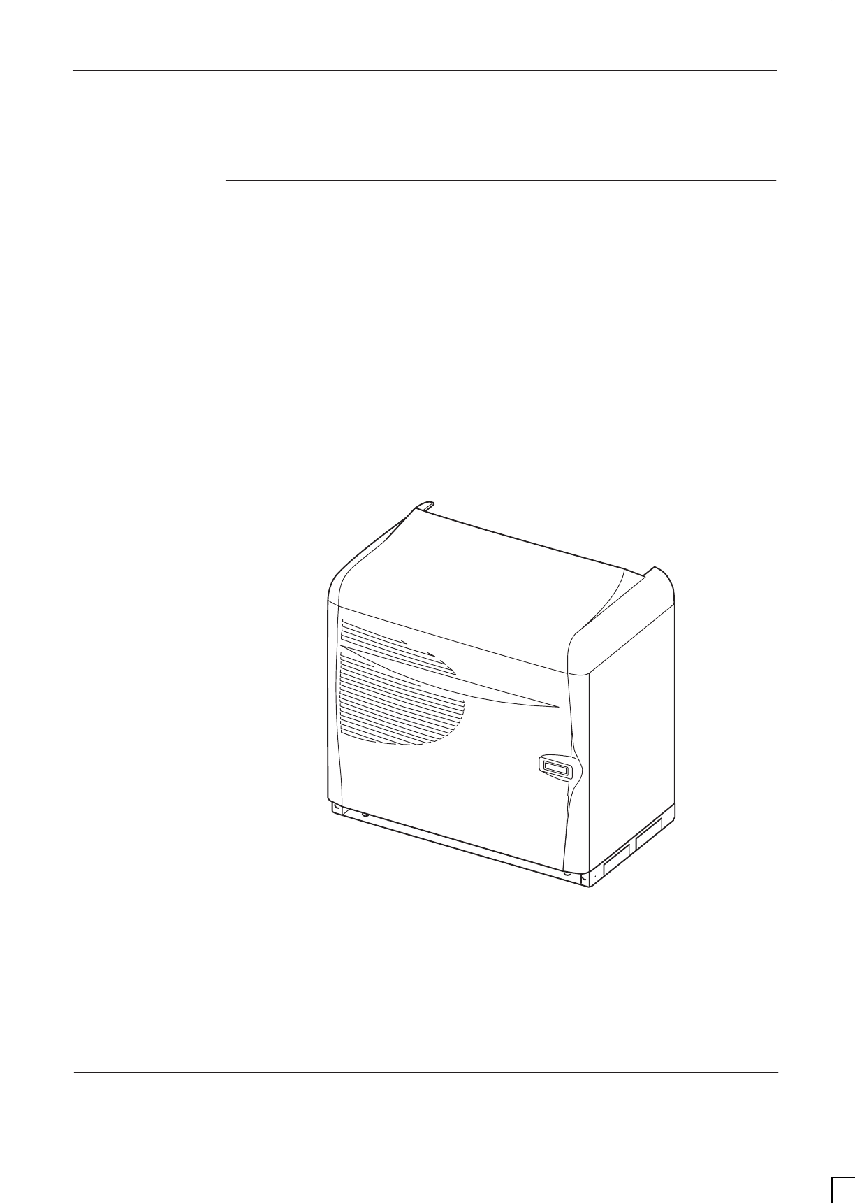
GSM-205-323 Equipment introduction and manual definition
31st Oct 01
Technical Description: Horizon
macro
indoor
68P02902W07-B
CONTROLLED INTRODUCTION
Tech. 1–1
Equipment introduction and manual definition
Overview of
Horizon
macro
indoor
The Horizon
macro
indoor is a six carrier base transceiver station (BTS) cabinet,
with variants that operate in the following frequency bands: GSM850, GSM/
EGSM900, DCS1800, and PCS1900.
Indoor cabinets operate from either –48/60 V dc (positive earth), +27 V dc
(negative earth), or wide input, nominal 120/240 V, ac single phase supplies.
An optional battery backup system is available for use with the –48/60 V dc
BTS, and is described in
Service Manual: Battery Backup System for
Horizonmacro Indoor: (GSM-205-023) Order number 68P02900W59
.
Cooling is provided by circulation fans located in the bottom of the unit.
Figure 1-1 shows an external view of a standard cabinet with an optional hood
fitted.
ig.225.rh
Figure 1-1 Indoor cabinet on plinth with optional hood

GSM-205-323
Equipment introduction and manual definition
31st Oct 01
Tech. 1–2
Technical Description: Horizon
macro
indoor
CONTROLLED INTRODUCTION
68P02902W07-B
Names and
acronyms for
main cabinet
equipment
This section is intended to give the reader a basic understanding of how
components interconnect.
The BTS cabinet consists of the cabinet frame structure, a main cage and a top
panel, and contains the following equipment, as shown in Figure 1-2:
SA digital module shelf, located in the lower right side of the cabinet. This
contains master and optional redundant digital modules:
– Fibre optic multiplexer (FMUX), 1 + 1 redundant (if required).
– Main control unit with dual FMUX (MCUF), 1 + 1 redundant (if
required).
– Network interface units (NIUs), four in total.
– An alarm board (no redundancy option).
– One or two (for redundancy) mBCU power supply modules (BPSMs).
SUp to three power supply modules (PSMs) and one circuit breaker module
(CBM) in the upper right portion of the cabinet. The PSMs are load
sharing, with the third PSM providing optional redundancy.
SUp to six compact transceiver units (CTUs), located in the left side of the
cabinet.
SFan modules mounted in the bottom of the cabinet, two 2-fan modules
and one 4-fan module.
SRF modules, mounted in the top panel, comprising transmit (Tx) blocks,
and a receive (Rx) module, the sectorized universal receiver front-end
(SURF). The various Tx blocks are listed in Specifications in this chapter.
SInterface panel, mounted in the top panel, for power and customer
communications connectors.
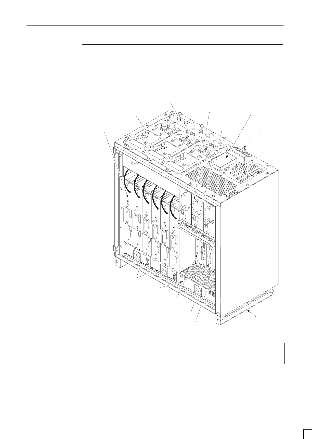
GSM-205-323 Equipment introduction and manual definition
31st Oct 01
Technical Description: Horizon
macro
indoor
68P02902W07-B
CONTROLLED INTRODUCTION
Tech. 1–3
Cabinet inside
view
Figure 1-2 shows the location of components and main headings for detailed
information in this technical description category of the manual.
CIRCUIT
BREAKER
MODULE (CBM)
RF MODULES POWER SUPPLIES AND
CIRCUIT BREAKER
TEMPERATURE
CONTROL SYSTEM
DIGITAL
MODULES
T43/BIB
MCUF
ALARM MODULE
FMUX/NIU/BPSM
(NOT VISIBLE)
TWO 2-FAN UNITS
ONE 4-FAN UNIT
SIX TRANSCEIVERS
(CTUs)
THREE Tx BLOCKS
(DCFs SHOWN AS EXAMPLE)
ONE SURF (Rx) THREE PSMs
(see NOTE)
INTERFACE
PANEL
CONNECTORS
TOP SECTION OF PLINTH
(SLIDES INTO BASE PLINTH)
DC POWER IN
NOTE Three PSMs = 2 + 1 redundant (if required). An optional
hold-up battery module may be installed instead of a
redundant PSM.
Figure 1-2 Cabinet with components identified (door and base plinth removed)

GSM-205-323
Equipment introduction and manual definition
31st Oct 01
Tech. 1–4
Technical Description: Horizon
macro
indoor
CONTROLLED INTRODUCTION
68P02902W07-B
Configuration
information
Configuration information can be found in
System Information: BSS Equipment
Planning: (GSM-001-103) Order number 68P02900W21.
Finding
information in
this manual
Each category and chapter has a table of contents (TOC). Headings are
designed to convey contents accurately, to enable manual search. The index
provides an alternative method of finding subsections of information. This
chapter provides a summary of the equipment, to enable readers to understand
terminology and thus locate information via the TOCs and index.
The service manual set comprises the four categories below:
SCategory 323
Provides an introduction, specification, and technical description.
SCategory 423
Provides the information for installation and commissioning.
SCategory 523
Provides information on maintenance and repair, with procedures to
change Field Replaceable Units (FRUs).
SCategory 623
Provides list of options and spares, with diagrams to illustrate FRUs.
The category 323 technical description is divided into chapters based on
functionality as shown in Figure 1-2:
SOverview and specifications
This chapter provides a summary of the equipment to enable the reader to
understand terminology, and thus locate information via the TOCs and
index.
SCabinet structure, including:
Interface panel, main cage, door and optional hood.
STemperature control system, including:
2-fan and 4-fan.
SCabinet power supply, including:
PSM, BPSM and circuit breaker module.
SRF modules, including:
CTU, SURF, Tx blocks and CCB.
SDigital modules, including:
MCUF, NIU, T43/BIB connections, FMUX and alarm module.
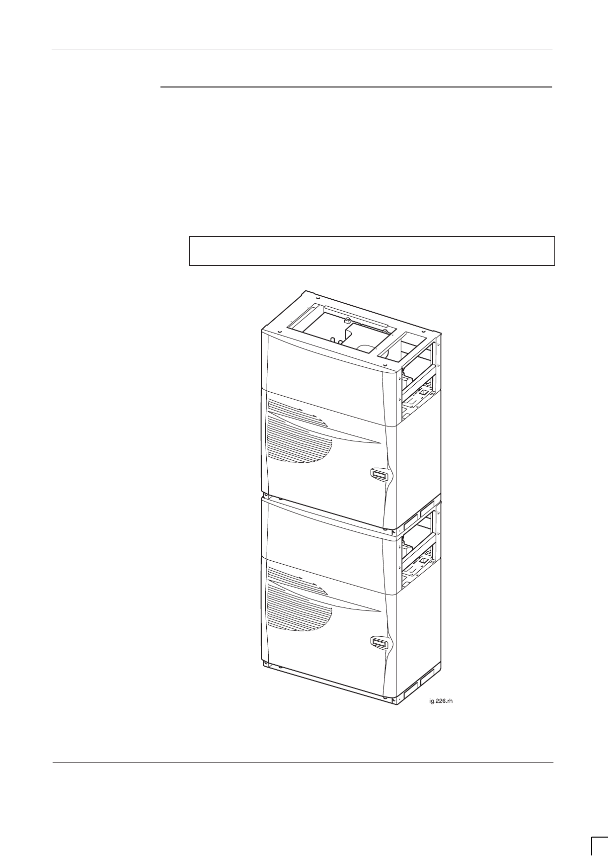
GSM-205-323 Equipment introduction and manual definition
31st Oct 01
Technical Description: Horizon
macro
indoor
68P02902W07-B
CONTROLLED INTRODUCTION
Tech. 1–5
Stacking
capability and
cabinet view
An optional stacking bracket enables any of the BTS variants to have a second
cabinet mounted on top of the first. The stacking bracket also enables an
optional Cavity Combining Block (CCB) to be installed in an optional stacking
bracket basket. A stacking bracket can be placed on top of the second (stacked)
cabinet, as shown in Figure 1-3.
NOTE CCBs are not currently available for the GSM850 or
PCS1900 BTS variants.
Figure 1-3 View of two cabinets stacked in maximum assembly
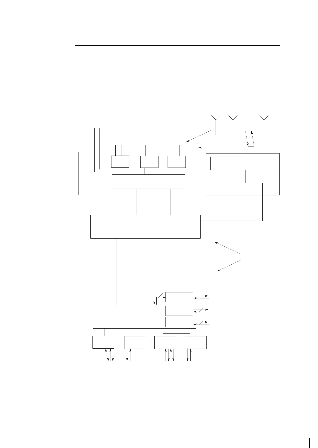
GSM-205-323
Equipment introduction and manual definition
31st Oct 01
Tech. 1–6
Technical Description: Horizon
macro
indoor
CONTROLLED INTRODUCTION
68P02902W07-B
Functional
diagram of
Horizon
macro
Figure 1-4 shows the functional modules of a Horizon
macro
. For clarity, only
one transceiver and one Tx block has been shown.
SWITCH (CONTROLLED BY CTU)
MCUF FMUX
FMUX
TO FMUX OF
EXTENSION CABINET
6
2
NIU
TO NETWORK
NIU NIU NIU
RF
MODULES
DIGITAL
MODULES
UP TO SIX TRANSCEIVERS
(CTUs)
UP TO THREE
Tx BLOCKS
ANTENNAS (Tx and Rx
SEPARATE OR COMBINED)
SURF
Rx0 Rx2Rx1
Rx A Rx B
Tx
TO SURF or
MCell6 Rx OF
EXTENSION
CABINET
Tx FILTER
Rx FILTER
RF LOOPBACK
EXT
FMUX
2
2
TO FMUX OF
EXTENSION CABINET
TO FMUX OF
EXTENSION CABINET
0B 1B1A 2A 2B0A
Figure 1-4 Functional diagram of cabinet components
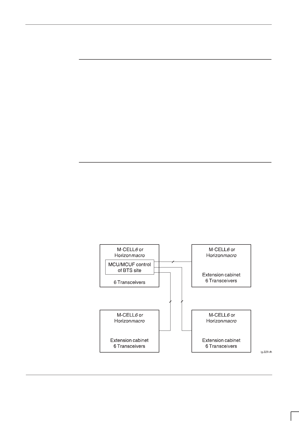
GSM-205-323 M-Cell
6
comparison with Horizon
macro
31st Oct 01
Technical Description: Horizon
macro
indoor
68P02902W07-B
CONTROLLED INTRODUCTION
Tech. 1–7
M-Cell
6
comparison with Horizon
macro
Comparison
overview
The Horizon
macro
is a replacement for M-Cellt
2/6
base stations, and the
GSM/EGSM900 and DCS1800 Horizon
macro
variants are directly compatible
with M-Cell
6
. For example, a mixture of up to four Horizon
macro
and M-Cell
6
BTSs can be combined to form a single site, with either a Horizon
macro
or an
M-Cell
6
being in control of the other units. Since many customers are familiar
with M-Cell
6
, and will use Horizon
macro
with M-Cell
6
, equivalent components
are described in this section, to assist understanding.
The Horizon
macro
is a single cabinet, using reduced size and higher reliability
components. The plinth base fix points are the same as M-Cell
6
, though direct
replacement may require repositioning, to allow for adequate cabinet spacing.
The Horizon
macro
can have a stacking bracket fitted to enable CCB installation,
and/or to enable mounting a second Horizon
macro
.
Horizon
macro
and M-Cell
6
compatibility
A 24-carrier BTS site (in an 8/8/8 configuration) can be achieved by combining
four units as shown in Figure 1-5. This is the maximum BTS size. Each unit can
be either a Horizon
macro
or an M-Cell
6
. Either a Horizon
macro
or an M-Cell
6
can control the other three units; the MCU of M-Cell
6
and the MCUF of
Horizon
macro
being identical in control function.
An MCUF can be fitted into an M-Cell
6
and will then function as an MCU. An
MCU cannot be fitted into a Horizon
macro
. Figure 1-5 shows a schematic
diagram of the digital connectons in a four cabinet BTS site.
22
2
Figure 1-5 Digital connections in maximum BTS site

GSM-205-323
M-Cell
6
comparison with Horizon
macro
31st Oct 01
Tech. 1–8
Technical Description: Horizon
macro
indoor
CONTROLLED INTRODUCTION
68P02902W07-B
Comparison of
Horizon
macro
and M-Cell
6
connections
and modules
Table 1-1 compares the main components of the Horizon
macro
, with equivalent
components of M-Cell
6
(the previous generation of equipment).
Table 1-1 Main components of Horizon
macro
and M-Cell
6
Function Horizon
macro
component M-Cell
6
equivalent
Input power conversion units PSM PSM (different)
Power to radios and BPSM Backplane Cables
Transceiver CTU TCU/TCU-B
Main processor board
(formerly GPROC, KSW and
GCLK boards in BTS4/5/6
(pre-M-Cell) equipment)
MCUF MCU
Connection radio to MCU Backplane FOX
Connection MCU to
transceivers in another cabinet MCUF internal FMUX
(two) or external
FMUX (one)
FMUX
Rx components and
distribution SURF DNLB & IADU
Radio to Rx components SURF Harness Cables
Tx components DCF, TDF, DDF, HCU
and CCB CBF, MPDM, HPDM
HC and CCB
Links to terrestrial network NIU NIU
E1/T1 links T43/BIB T43/BIB
Power for digital boards BPSM BPSM
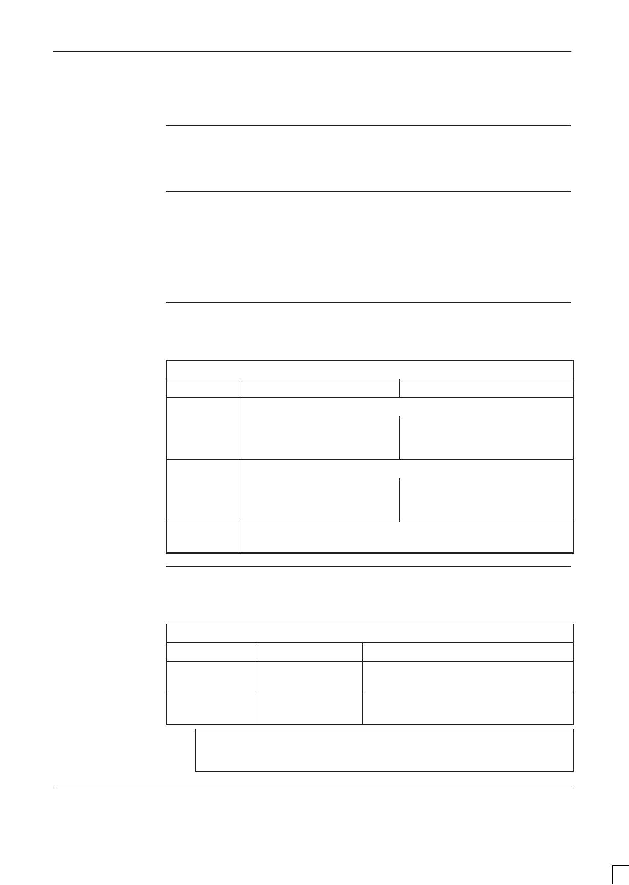
GSM-205-323 Specifications
31st Oct 01
Technical Description: Horizon
macro
indoor
68P02902W07-B
CONTROLLED INTRODUCTION
Tech. 1–9
Specifications
Overview of
specifications
All Horizon
macro
specifications are included in this section.
Software
requirements
The GSM/EGSM900 and DCS1800 BTSs require software release GSR4 (or
later) in the network.
The GSM850 and PCS1900 BTSs require software release GSR5.1 (or later) in
the network.
Approval and
safety
Table 1-2 lists the specifications with which the Horizon
macro
indoor complies.
Table 1-2 Horizon
macro
specification compliance
GSM/EGSM900 & DCS1800 GSM850 & PCS1900
Type
l
ETS 301 502
approval CFR47 Part 2
CFR47 Part 22 (850 only)
CFR47 Part 24 (1900 only)
EMC EN301 489-8
CFR 47 Part 2 and 15
CFR47 Part 22 (850 only)
CFR47 Part 24 (1900 only)
Safety EN 60215, IEC 60215, EN 60950, IEC 950,
CSA 22.2 No. 950, UL 1950
Environmental
limits
Table 1-3 lists the operating and storage environmental limits.
Table 1-3 Environmental limits
Environment Temperature Relative Humidity
Operating –5 _C to + 45 _C. 5% to 100% relative humidity, not to
exceed 0.029 g water / m3 dry air.
Storage –45 _C to +70 _C. 8% to 100% relative humidity, not to
exceed 0.029 g water / m3 dry air.
NOTE This specification is valid up to 3 km altitude,
corresponding to an atmospheric pressure range of 648 to
1048 millibars.
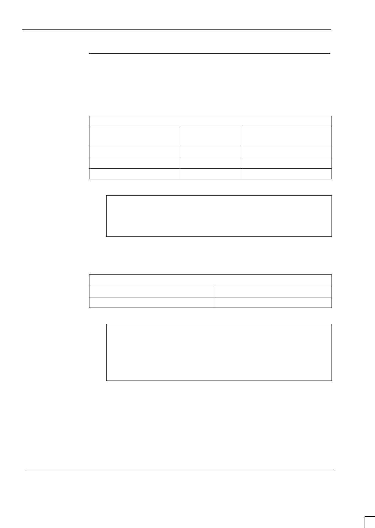
GSM-205-323
Specifications
31st Oct 01
Tech. 1–10
Technical Description: Horizon
macro
indoor
CONTROLLED INTRODUCTION
68P02902W07-B
Power
requirements
Cabinet power supply requirements
Table 1-4 lists the power supply requirements for the different power supply
options.
Table 1-4 Main indoor cabinet power supply requirements
Nominal Voltage Voltage supply
range Current supply maximum
+27 V dc (negative earth) +20 to +30 V dc 64 A (at nominal voltage)
–48 V dc (positive earth) –39 to –72 V dc 36 A (at nominal voltage)
120/240 V ac (50 – 60 Hz) 88 to 264 7.5 A (at nominal voltage)
NOTE Voltage transients must be less than 35 V peak amplitude
(never below 0 V). Ripple and noise must be less than 200
mV p-p (30 mV rms) over 10 Hz to 14 MHz. Voltage
application stabilization must be within the specified range
in less than 1 second.
Power consumption
Table 1-5 lists typical and maximum power consumption values
Table 1-5 Power consumption of full cabinet, including digital redundancy
Typical measured consumption Maximum power consumption
1400 watts 1700 watts
NOTE Maximum power consumption figures are theoretical
values derived under extreme conditions and are affected
by variables such as temperature, component tolerances,
transmission power and supply voltage.
Although these figures must be considered when planning
site power requirements, typical measured consumption
values will be lower.

GSM-205-323 Specifications
31st Oct 01
Technical Description: Horizon
macro
indoor
68P02902W07-B
CONTROLLED INTRODUCTION
Tech. 1–11
Maximum thermal dissipation
Thermal dissipation has to remove the energy of maximum power consumption,
less RF power output of the six transceivers.
Maximum power consumption: 1700 W.
Six CTUs at full power at DCF Tx blocks:
1800 MHz (6 x 16 = 96) approx. 100 W.
900 MHz (6 x 20 = 120) 120 W.
Maximum thermal dissipation 1800 MHz: 1700 – 100 = 1600 W.
Maximum thermal dissipation 900 MHz: 1700 – 120 = 1580 W.
NOTE Thermal dissipation figures are not currently available for
when 850 MHz or 1900 MHz CTUs are used.
RF power
output
Table 1-6 lists the RF power output of the CTU types.
Table 1-6 CTU RF power output at Tx connector
GSM850 and EGSM900 DCS1800 and PCS1900
60 W (47.8 dBm) +/– 1.0 dB 50 W (47.0 dBm) +/–1.0 dB
Table 1-7 lists the expected power output from the various Tx blocks for both
types of CTU.
Table 1-7 RF power output at cabinet after Tx blocks
Tx block GSM850 EGSM900 DCS1800 PCS1900
TDF 40 W
(46.0 dBm) 32 W
(45.1 dBm)
DCF 20 W
(43.0 dBm) 16 W
(42.1 dBm)
DDF 8.5 W
(39.3 dBm) 7 W
(38.5 dBm)
CCB* n/a 20 W
(43.0 dBm) 16 W
(42.1 dBm) n/a
* For a six-channel configuration with minimum cavity separation of 800 kHz.
NOTE CCBs are not currently available for the GSM850 or
PCS1900 variants.

GSM-205-323
Specifications
31st Oct 01
Tech. 1–12
Technical Description: Horizon
macro
indoor
CONTROLLED INTRODUCTION
68P02902W07-B
Sensitivity
The receive sensitivity of the equipment is shown in Table 1-8.
Table 1-8 Rx sensitivity *
Frequency Band Without Duplexer With Duplexer
850 MHz –107 dBm –106 dBm
900 MHz –107 dBm –106 dBm
1800 MHz –108.5 dBm –107.5 dBm
1900 MHz –107 dBm –106 dBm
* Guaranteed over all channel types, fading profiles, RF frequencies
and operating conditions.
Battery backup
The Horizon
macro
indoor cabinet has no internal battery backup as standard.
An optional hold-up battery module, (sufficient to provide ten seconds of backup
power), can be fitted in the PSM shelf, in an empty slot or in place of the
redundant PSM. The optional hold-up battery module is described in chapter 4
of this category in Hold-up battery module
Additional battery backup capacity can be provided by installation of an optional
battery back up system, described in
Service manual: Battery backup system for
Horizonmacro indoor; GSM-205-023, 68P02900W59
.
BSC
connectivity
options
Options exist for E1, T1 and HDSL (star and daisy chain) connection.
Indoor cabinet
dimensions
The dimensions of cabinets are shown in Table 1-9.
Table 1-9 Cabinet dimensions
Cabinet type Height Width Depth
Cabinet (without hood) 750 mm 700 mm 430 mm
Cabinet with optional hood 870 mm 700 mm 430 mm
Cabinet with stacking bracket (to hold CCB) 1025 mm 700 mm 430 mm
Two cabinets, with stacking bracket
between, and optional hood on top 1900 mm 700 mm 430 mm
Two cabinets, with stacking bracket
between, and stacking bracket on top. 2050 mm 700 mm 430 mm
The optional hood allows cables to enter the cabinet from the back and above.
The stacking bracket allows a second cabinet to be stacked on top of the first
cabinet. The stacking bracket can also contain a metal basket, in which CCBs
are fitted (the only Tx unit that cannot fit in the cabinet itself).
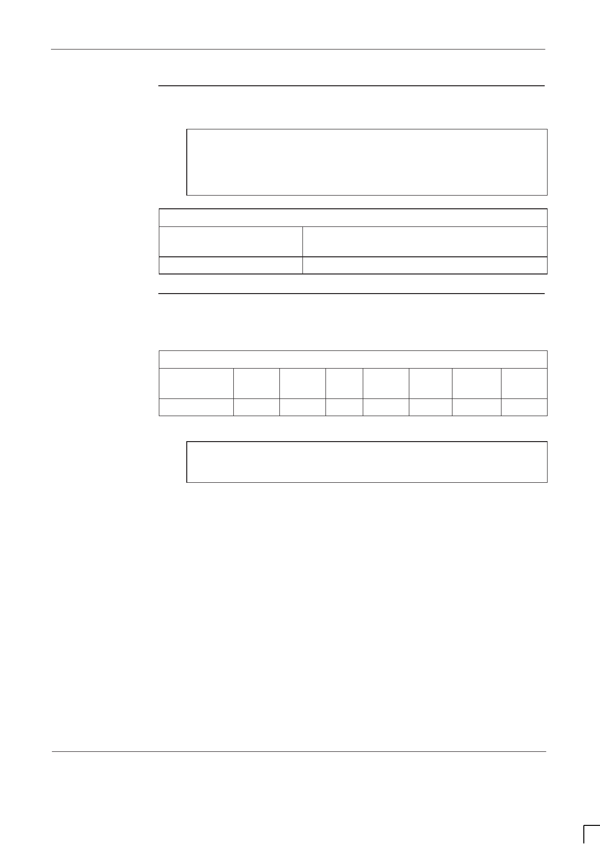
GSM-205-323 Specifications
31st Oct 01
Technical Description: Horizon
macro
indoor
68P02902W07-B
CONTROLLED INTRODUCTION
Tech. 1–13
Weights
The maximum weight of the cabinet is shown in Table 1-10.
CAUTION Consider future expansion. Another cabinet may be added
by stacking on top of the existing cabinet. This, if used
with stacking units on both, each with CCBs, and
associated cables, could result in a total weight of 280 kg.
Ensure floor is capable of supporting this weight.
Table 1-10 Main indoor cabinet weights (with six transceivers)
Cabinet with plinth and
optional hood Cabinet with plinth, stacking bracket and
CCB
115 kg 130 kg
Torque values
Table 1-11 details torque values used during installation, maintenance and
repair procedures.
Table 1-11 Torque values for all cabinet screws/bolts and RF connectors
Size of
screw/bolt M4 M6 M8 M10 SMA N-type 7/16
Torque value 2.2 Nm 3.4 Nm 5 Nm 10 Nm 1 Nm 3.4 Nm 25 Nm
NOTE Torque values used with M12 anchor bolts will depend on
the anchor bolt manufacturer. Check manufacturer’s data
for correct values.

GSM-205-323
Specifications
31st Oct 01
Tech. 1–14
Technical Description: Horizon
macro
indoor
CONTROLLED INTRODUCTION
68P02902W07-B
Frequency
capability
Frequency hopping
The Horizon
macro
supports baseband frequency hopping (BBH) and
synthesizer frequency hopping (SFH).
NOTE Baseband frequency hopping is not supported in the
GSM850 and PCS1900 Horizon
macro
variants.
Frequency band characteristics
BTS radio channels (RF carriers) are full duplex (transmit and receive) with the
characteristics listed in Table 1-12 for GSM/EGSM900 and DCS1800 BTSs and
in Table 1-13 for GSM850 and PCS1900 BTSs.
Table 1-12 Frequency band characteristics – GSM/EGSM900 and DCS1800
GSM900 EGSM DCS1800
Transmit frequency band
(MHz) 935 to 960 925 to 960 1805 to 1880
Receive frequency band (MHz) 890 to 915 880 to 915 1710 to 1785
Transmit/receive duplex
separation (MHz) 45 45 95
Channel width (kHz) 200 200 200
Number of channels 124 174 374
Transmit frequency guard
bands (MHz) 935.0 to
935.1
959.9 to
960.0
925.0 to
925.1
959.9 to
960.0
1805.0 to
1805.1
1879.9 to
1880.0
Receive frequency guard
bands (MHz) 890.0 to
890.1
914.9 to
915.0
880.0 to
880.1
914.9 to
915.0
1710.0 to
1710.1
1784.9 to
1785.0
Transmit channel centre
frequency (MHz) Even 10ths
of a MHz
from 935.2
to 959.8
Even 10ths
of a MHz
from 925.2
to 959.8
Even 10ths of
a MHz from
1805.2 to
1879.8
Receive channel centre
frequency (MHz) Even 10ths
of a MHz
from 890.2
to 914.8
Even 10ths
of a MHz
from 880.2
to 914.8
Even 10ths of
a MHz from
1710.2 to
1784.8

GSM-205-323 Specifications
31st Oct 01
Technical Description: Horizon
macro
indoor
68P02902W07-B
CONTROLLED INTRODUCTION
Tech. 1–15
Table 1-13 Frequency band characteristics – GSM850 and PCS1900
GSM850 PCS1900
Transmit frequency band (MHz) 869 to 894 1930 to 1990
Receive frequency band (MHz) 824 to 849 1850 to 1910
Transmit/receive duplex
separation (MHz) 45 80
Channel width (kHz) 200 200
Number of channels 124 299
Transmit frequency guard
bands (MHz) 869.0 to 869.1
893.9 to 894.0 1930.0 to 1930.1
1989.9 to 1990.0
Receive frequency guard bands
(MHz) 824.0 to 824.1
848.9 to 849.0 1850.0 to 1850.1
1909.9 to 1910.0
Transmit channel centre
frequency (MHz) Even 10ths of a
MHz from
869.2 to 893.8
Even 10ths of a
MHz from
1930.2 to 1989.8
Receive channel centre
frequency (MHz) Even 10ths of a
MHz from
824.2 to 848.8
Even 10ths of a
MHz from
1850.2 to 1909.8
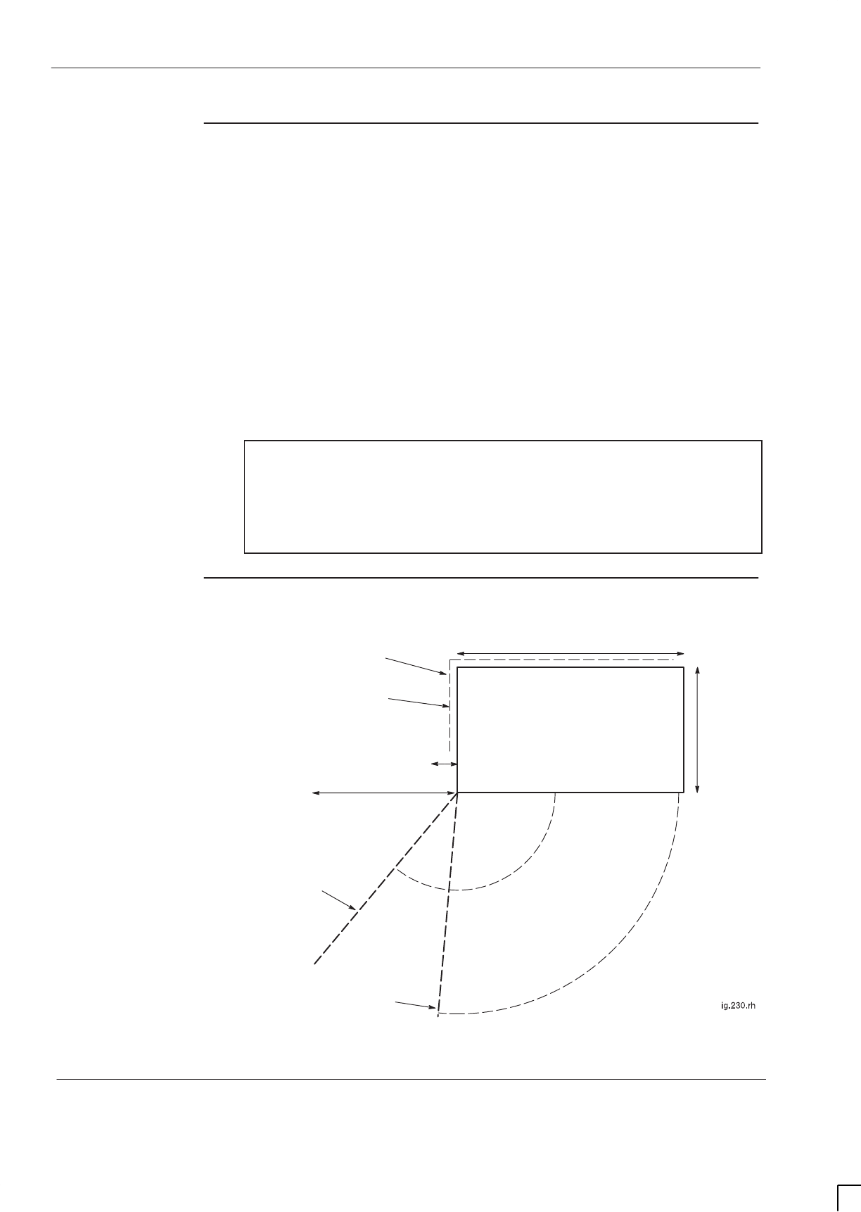
GSM-205-323
Specifications
31st Oct 01
Tech. 1–16
Technical Description: Horizon
macro
indoor
CONTROLLED INTRODUCTION
68P02902W07-B
Structural
considerations
Adequate clearance must be provided at the front of the equipment for
operation and maintenance purposes. There must be adequate side clearance
(50 mm) to enable the door to open beyond 90° (see Figure 1-6). The door can
also stop at 95° and 130° , but this is only to protect the door, or give optional
additional operator space.
The cabinet ventilation entry can be solely from the bottom front of the cabinet.
This allows a cabinet to be placed against a wall. However, if the unit is placed
50 mm from back or side obstructions, such as wall or other cabinets, the
ventilation will be improved, and fan noise reduced.
Up to 100 mm rear space may be required for cables if using stacking bracket.
The foundation or structure on which the BTS cabinet is mounted must be of
sufficient strength to support a maximum gross weight of 130 kg for a single
cabinet or 280 kg for two stacked cabinets.
NOTE In seismically active areas, Motorola suggest using a
qualified structural engineer to assess frame mounting
requirements, such as floor construction, mounting
anchors, cell site construction and to provide a suitable
design for top frame support if a stacked configuration is
required.
Layout plan
Figure 1-6 shows the cabinet installation layout plan.
700 mm door at
first position (95°)
100 mm clearance if using stacking
bracket to allow cable space
700 mm door at
second position (130°)
430 mm
700 mm
INDOOR CABINET
50 mm minimum side
clearance for door opening
70 mm width
when door at 95°
500 mm width when
door at 130°
Figure 1-6 Indoor cabinet site layout plan

31st Oct 01
Technical Description: Horizon
macro
indoor
68P02902W07-B
CONTROLLED INTRODUCTION
i
Chapter 2
Cabinet structure

GSM-205-323
31st Oct 01
ii
Technical Description: Horizon
macro
indoor
CONTROLLED INTRODUCTION
68P02902W07-B

GSM-205-323
31st Oct 01
Technical Description: Horizon
macro
indoor
68P02902W07-B
CONTROLLED INTRODUCTION
iii
Chapter 2
Cabinet structure i. . . . . . . . . . . . . . . . . . . . . . . . . . . . . . . . . . . . . . . . . . . . . .
Cabinet structure of Horizonmacro indoor Tech. 2–1. . . . . . . . . . . . . . . . . . . . . . . . . . . . . . .
External cabinet view Tech. 2–1. . . . . . . . . . . . . . . . . . . . . . . . . . . . . . . . . . . . . . . . . . . .
Overview of structure description Tech. 2–2. . . . . . . . . . . . . . . . . . . . . . . . . . . . . . . . .
Space required around cabinet Tech. 2–2. . . . . . . . . . . . . . . . . . . . . . . . . . . . . . . . . . .
Filled cabinet view Tech. 2–3. . . . . . . . . . . . . . . . . . . . . . . . . . . . . . . . . . . . . . . . . . . . . .
Empty cabinet and SURF harness Tech. 2–4. . . . . . . . . . . . . . . . . . . . . . . . . . . . . . . . . . . . .
SURF harness and cabinet attachment Tech. 2–4. . . . . . . . . . . . . . . . . . . . . . . . . . .
Cabinet view with installed SURF harness Tech. 2–4. . . . . . . . . . . . . . . . . . . . . . . . .
SURF harness view Tech. 2–5. . . . . . . . . . . . . . . . . . . . . . . . . . . . . . . . . . . . . . . . . . . . .
Top panel Tech. 2–6. . . . . . . . . . . . . . . . . . . . . . . . . . . . . . . . . . . . . . . . . . . . . . . . . . . . . . . . . . .
Top panel description Tech. 2–6. . . . . . . . . . . . . . . . . . . . . . . . . . . . . . . . . . . . . . . . . . . .
Top panel view Tech. 2–6. . . . . . . . . . . . . . . . . . . . . . . . . . . . . . . . . . . . . . . . . . . . . . . . .
Cage backplane interface panel harness assembly (CBIA) Tech. 2–7. . . . . . . . . . . . . . . .
CBIA overview Tech. 2–7. . . . . . . . . . . . . . . . . . . . . . . . . . . . . . . . . . . . . . . . . . . . . . . . . .
CBIA and interface panel schematic view Tech. 2–7. . . . . . . . . . . . . . . . . . . . . . . . . .
Backplane and harness view including door switch and heat sensors Tech. 2–8. .
CBIA cage function and diagram Tech. 2–9. . . . . . . . . . . . . . . . . . . . . . . . . . . . . . . . . .
CBIA harness function Tech. 2–9. . . . . . . . . . . . . . . . . . . . . . . . . . . . . . . . . . . . . . . . . . .
CBIA backplane function Tech. 2–10. . . . . . . . . . . . . . . . . . . . . . . . . . . . . . . . . . . . . . . . .
Attachment of cage to cabinet Tech. 2–10. . . . . . . . . . . . . . . . . . . . . . . . . . . . . . . . . . . .
Interface panel function Tech. 2–11. . . . . . . . . . . . . . . . . . . . . . . . . . . . . . . . . . . . . . . . . .
Interface panel diagram Tech. 2–11. . . . . . . . . . . . . . . . . . . . . . . . . . . . . . . . . . . . . . . . . .
Interface panel pinouts Tech. 2–11. . . . . . . . . . . . . . . . . . . . . . . . . . . . . . . . . . . . . . . . . .
Cabinet door and optional hood Tech. 2–12. . . . . . . . . . . . . . . . . . . . . . . . . . . . . . . . . . . . . . . .
Door function Tech. 2–12. . . . . . . . . . . . . . . . . . . . . . . . . . . . . . . . . . . . . . . . . . . . . . . . . . .
Door external and internal view Tech. 2–12. . . . . . . . . . . . . . . . . . . . . . . . . . . . . . . . . . .
Hood function Tech. 2–13. . . . . . . . . . . . . . . . . . . . . . . . . . . . . . . . . . . . . . . . . . . . . . . . . .
View of hood Tech. 2–13. . . . . . . . . . . . . . . . . . . . . . . . . . . . . . . . . . . . . . . . . . . . . . . . . . .
Securing pins and hood removal Tech. 2–13. . . . . . . . . . . . . . . . . . . . . . . . . . . . . . . . . .
Stacking bracket and CCB basket Tech. 2–14. . . . . . . . . . . . . . . . . . . . . . . . . . . . . . . . . . . . . .
Stacking bracket function Tech. 2–14. . . . . . . . . . . . . . . . . . . . . . . . . . . . . . . . . . . . . . . .
Stacking bracket diagram Tech. 2–14. . . . . . . . . . . . . . . . . . . . . . . . . . . . . . . . . . . . . . . .
Stacking bracket front cover function Tech. 2–15. . . . . . . . . . . . . . . . . . . . . . . . . . . . . .
View of stacked cabinets Tech. 2–15. . . . . . . . . . . . . . . . . . . . . . . . . . . . . . . . . . . . . . . . .

GSM-205-323
31st Oct 01
iv
Technical Description: Horizon
macro
indoor
CONTROLLED INTRODUCTION
68P02902W07-B
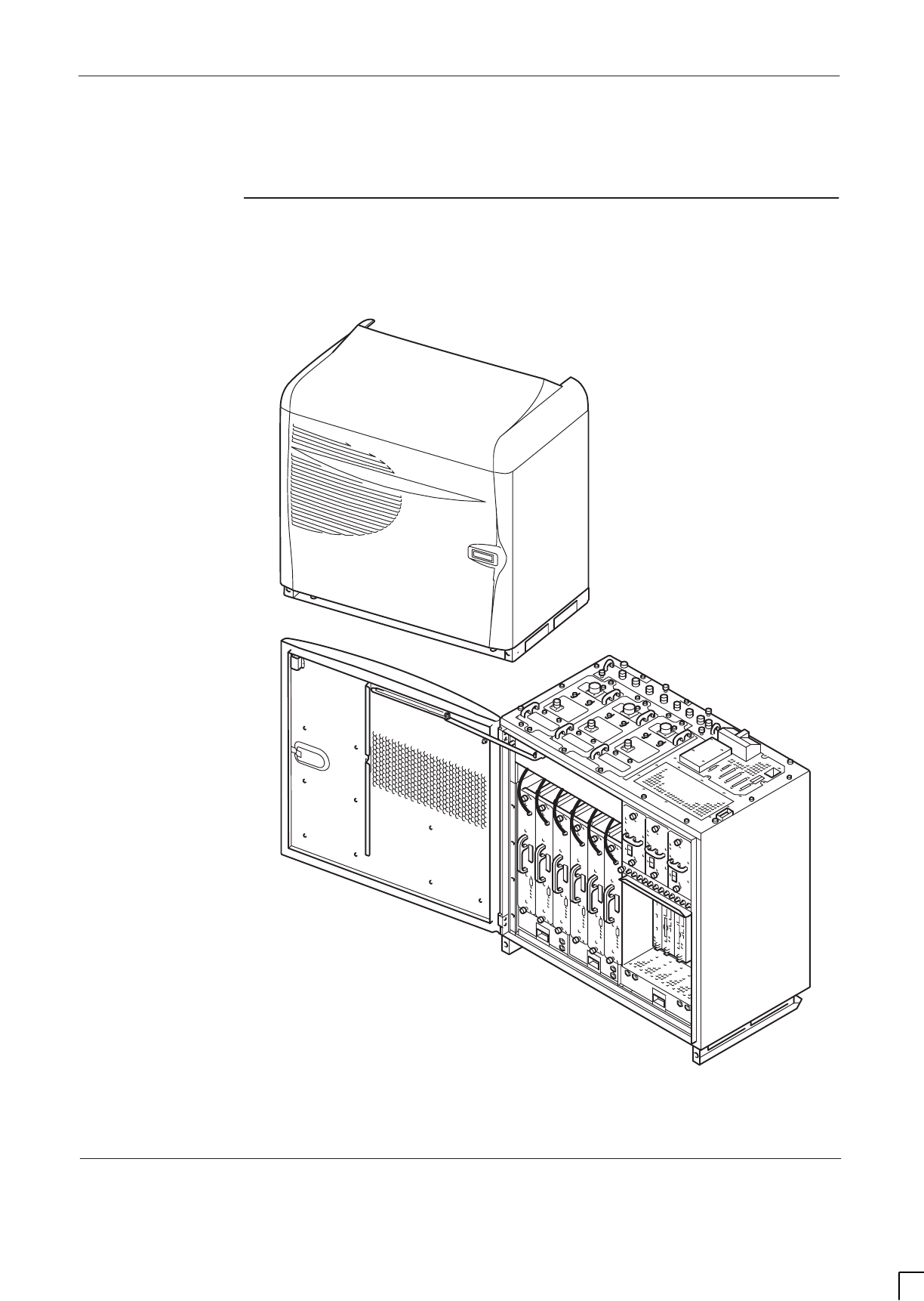
GSM-205-323 Cabinet structure of Horizon
macro
indoor
31st Oct 01
Technical Description: Horizon
macro
indoor
68P02902W07-B
CONTROLLED INTRODUCTION
Tech. 2–1
Cabinet structure of Horizon
macro
indoor
External cabinet
view
Figure 2-1 shows an external view of a closed cabinet with optional hood, and a
cabinet with door open and no hood.
Figure 2-1 Closed cabinet and cabinet with hood removed and door open

GSM-205-323
Cabinet structure of Horizon
macro
indoor
31st Oct 01
Tech. 2–2
Technical Description: Horizon
macro
indoor
CONTROLLED INTRODUCTION
68P02902W07-B
Overview of
structure
description
The equipped cabinet is shown in Figure 2-2. The cabinet, intended for
minimum maintenance and maximum ease of module replacement, and has
access only from the front and the top.
This chapter describes the cabinet structure and inner connections to assist
understanding of the cabinet functions. There should be no need to dismantle
the cabinet beyond Field Replaceable Unit (FRU) level.
The cabinet structure components are explained in the following sections:
Empty cabinet and SURF harness
This section describes the empty cabinet and the SURF harness connections
between the SURF and the backplane and transceivers.
Top panel
This section describes the bare top panel with all the modules removed.
Cage backplane interface panel harness assembly (CBIA)
This section describes the CBIA. It also describes the backplane connections
between all modules, and the harness from the backplane to the interface top
panel connectors.
Door and hood
This section describes the structure and function of the door and optional hood.
Stacking bracket and CCB basket
This section describes the stacking bracket. It is used for mounting a second
cabinet on top of the first, and/or providing a mounting position for CCBs.
Space required
around cabinet
See Specifications in Chapter 1.
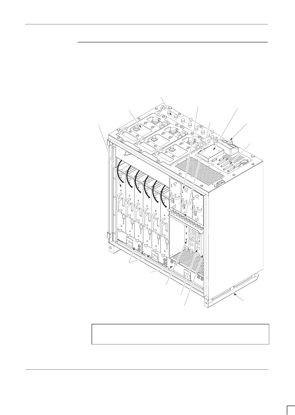
GSM-205-323 Cabinet structure of Horizon
macro
indoor
31st Oct 01
Technical Description: Horizon
macro
indoor
68P02902W07-B
CONTROLLED INTRODUCTION
Tech. 2–3
Filled cabinet
view
Figure 2-2 shows a cabinet with maximum number of modules installed. Further
information is detailed in the later technical description chapters.
CIRCUIT
BREAKER
MODULE (CBM)
RF MODULES POWER SUPPLIES AND
CIRCUIT BREAKER
TEMPERATURE
CONTROL SYSTEM
DIGITAL
MODULES
T43/BIB
MCUF
ALARM MODULE
FMUX/NIU/BPSM
(NOT VISIBLE)
TWO 2-FAN UNITS
ONE 4-FAN UNIT
SIX TRANSCEIVERS
(CTUs)
THREE Tx BLOCKS
(DCFs SHOWN AS EXAMPLE)
ONE SURF (Rx) THREE PSMs
(see NOTE)
INTERFACE
PANEL
CONNECTORS
TOP SECTION OF PLINTH
(SLIDES INTO BASE PLINTH)
DC POWER IN
NOTE Three PSMs = 2 + 1 redundant (if required). An optional
hold-up battery module may be installed instead of a
redundant PSM.
Figure 2-2 Cabinet, without door or hood, showing main components
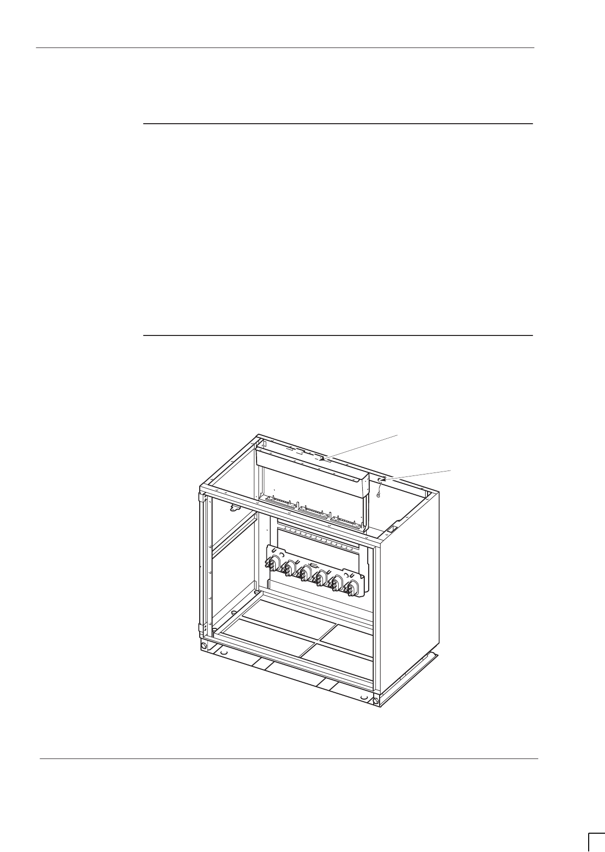
GSM-205-323
Empty cabinet and SURF harness
31st Oct 01
Tech. 2–4
Technical Description: Horizon
macro
indoor
CONTROLLED INTRODUCTION
68P02902W07-B
Empty cabinet and SURF harness
SURF harness
and cabinet
attachment
The SURF harness is fitted on the back wall of the cabinet, as shown in
Figure 2-3. The chassis of the SURF harness supports the SURF module.
The SURF harness provides:
SThree connectors to the SURF, for RF and power.
SOne RF connector to each CTU, consisting of three inputs, one each for
RxA, RxB and RF loopback test, as shown in Figure 2-4. The RF
connectors are free floating to ensure fitting of CTU modules.
SOne connector to the backplane, for power from the PSMs.
Cabinet view
with installed
SURF harness
Figure 2-3 shows the SURF harness installed in an empty cabinet, with, for
clarity, SURF harness cables not shown.
ig.232.rh
SURF HARNESS
EARTH CABLE FOR
MAIN CAGE
Figure 2-3 SURF harness installed in empty cabinet.
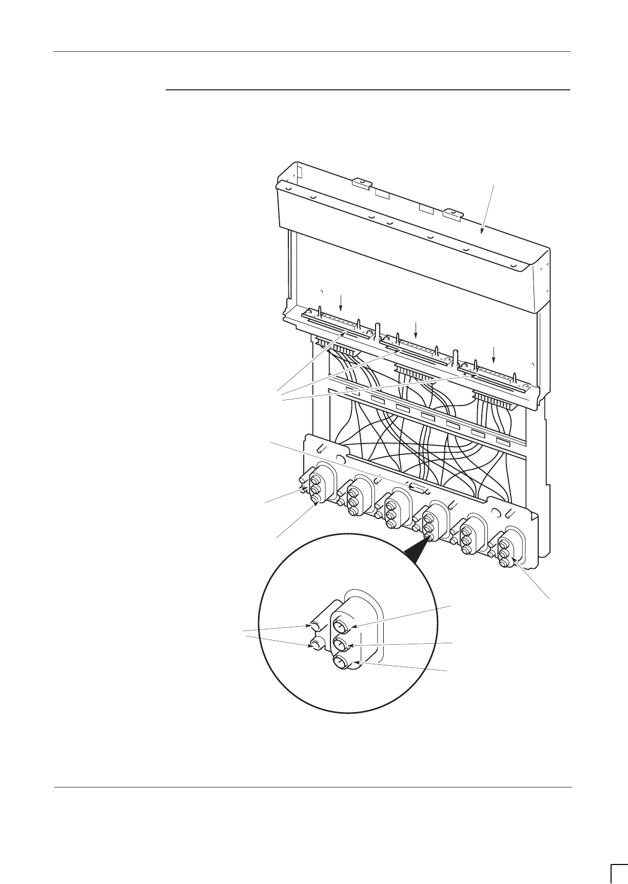
GSM-205-323 Empty cabinet and SURF harness
31st Oct 01
Technical Description: Horizon
macro
indoor
68P02902W07-B
CONTROLLED INTRODUCTION
Tech. 2–5
SURF harness
view
Figure 2-4 shows the SURF harness with connectors indicated.
ig.233.rh
CONNECTOR FOR
EACH CTU
POWER CONNECTOR TO
BACKPLANE
SLOT FOR SURF
MODULE
LOCATING PINS
RxA
RF LOOPBACK
TEST PORT (L)
RxB
RxA X 6
RxB X 6
RF LOOPBACK X 6
CTU 0
CTU 5
THREE CONNECTORS
TO SURF
Figure 2-4 SURF harness with connectors indicated
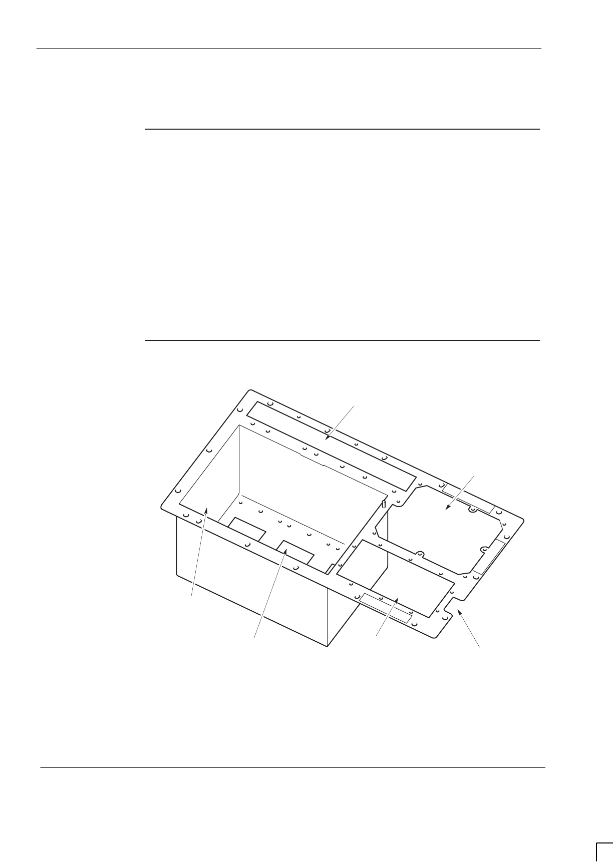
GSM-205-323
Top panel
31st Oct 01
Tech. 2–6
Technical Description: Horizon
macro
indoor
CONTROLLED INTRODUCTION
68P02902W07-B
Top panel
Top panel
description
The top panel provides:
SA basket to hold up to three Tx blocks. This includes three holes to
enable connection of CTU Tx cables to the underside of each Tx block.
The holes also allow cooling of the Tx blocks from underneath.
SA slot for insertion of the SURF module.
SA location hole for the interface panel.
SAn area for ventilation purposes above the PSMs.
SA cable hole for fibre optic extension cables from the MCUF FMUX to an
FMUX of another cabinet.
Top panel view
Figure 2-5 shows a top panel with major features labelled.
ig.235.rh
SLOT FOR SURF MODULE
LOCATION HOLE
FOR INTERFACE
PANEL
VENTILATION PANEL
(LOCATED ABOVE PSMs)
BASKET TO HOLD
THREE Tx BLOCKS
HOLE FOR ONE Tx BLOCK
CTU CONNECTIONS CABLE HOLE FOR FIBRE
OPTIC EXTENSION CABLES
Figure 2-5 Top panel with major features labelled
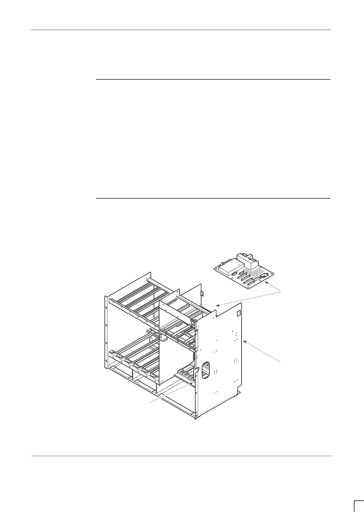
GSM-205-323 Cage backplane interface panel harness assembly (CBIA)
31st Oct 01
Technical Description: Horizon
macro
indoor
68P02902W07-B
CONTROLLED INTRODUCTION
Tech. 2–7
Cage backplane interface panel harness assembly (CBIA)
CBIA overview
The CBIA provides a platform for module installation and power and digital
signal interconnection to cabinet modules. The CBIA consists of:
SThe main cage - providing compartments for fans, CTUs, digital modules,
BPSMs, PSMs and CBM.
SThe backplane - routes power and signals for all cage modules and power
to the SURF.
SThe harness - links the backplane to the interface panel.
SThe interface panel - carries the T43/BIB, the required power and
communications connectors.
CBIA and
interface panel
schematic view
Figure 2-6 shows the CBIA main cage and the interface panel.
ig.236.rh
DIGITAL MODULE
SECTION OF CAGE
INTERFACE
PANEL
MAIN
CAGE
BACKPLANE
ATTACHED TO
ENTIRE BACK
OF CAGE
HARNESS LINKS
BACKPLANE
CONNECTORS TO
UNDERSIDE OF
INTERFACE PANEL
Figure 2-6 View of CBIA cage and the interface panel
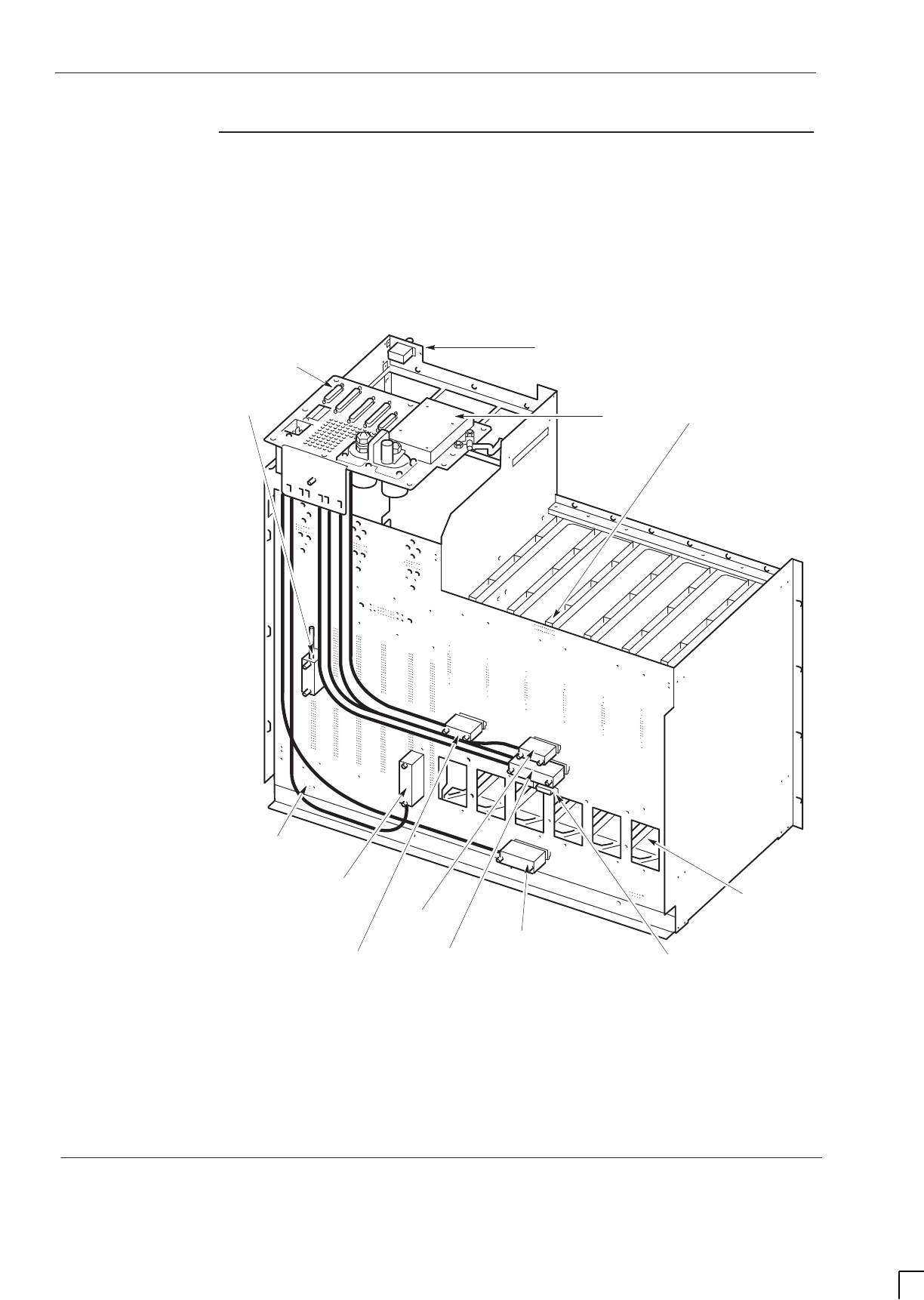
GSM-205-323
Cage backplane interface panel harness assembly (CBIA)
31st Oct 01
Tech. 2–8
Technical Description: Horizon
macro
indoor
CONTROLLED INTRODUCTION
68P02902W07-B
Backplane and
harness view
including door
switch and heat
sensors
Figure 2-7 shows the CBIA harness linking the interface panel and the
backplane at rear of main cage. Each backplane harness connector is
identified.
ig.237.rh
ICS J26
DOOR SWITCH
THREE HEAT
SENSORS
DOOR SWITCH
CONNECTOR J55
SIX CTU
CONNECTOR
HOLES FOR
SURF
HARNESS
POWER
CONNECTOR
FOR SURF
HARNESS
NIU to T43/BIB
J21
INTERFACE
PANEL
EXTERNAL
ALARMS J23
GPS J22
(if fitted)
RTC J32
PIX J25
T43/BIB
Figure 2-7 Rear view of CBIA showing backplane and harness
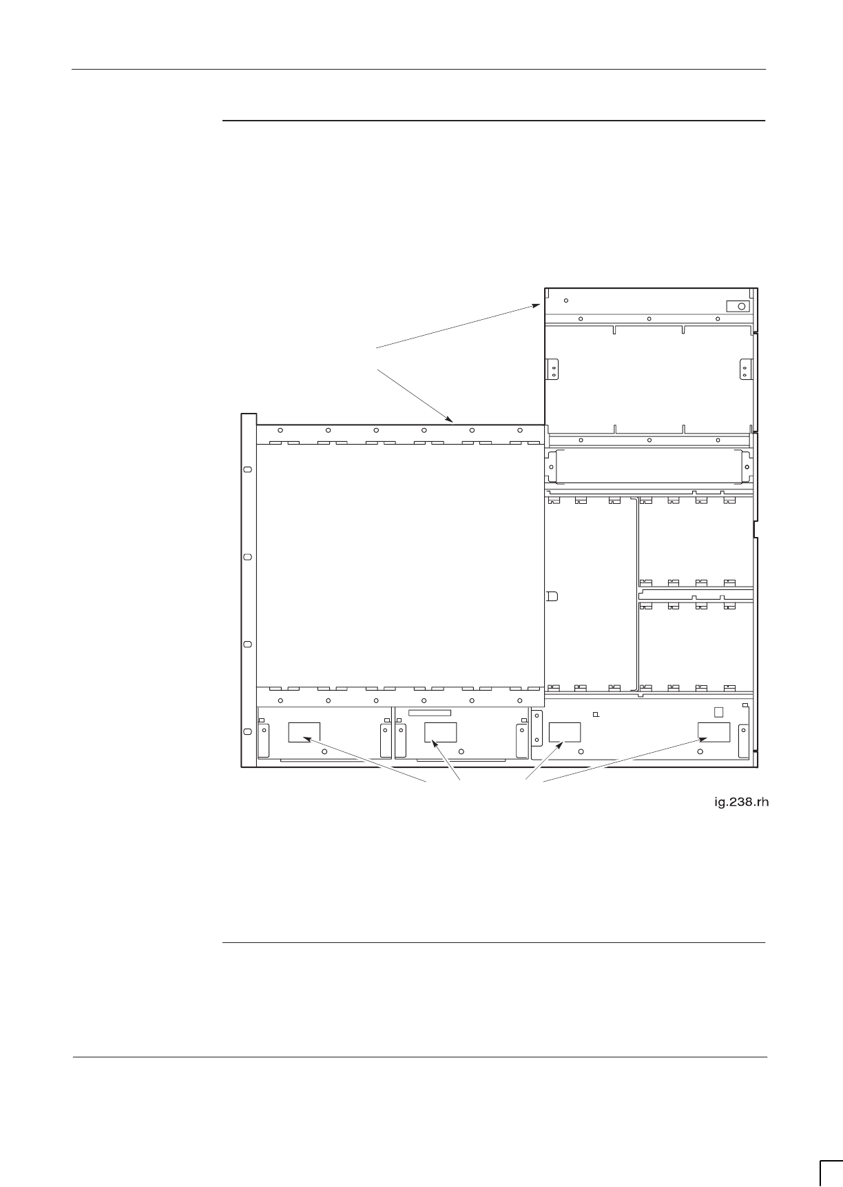
GSM-205-323 Cage backplane interface panel harness assembly (CBIA)
31st Oct 01
Technical Description: Horizon
macro
indoor
68P02902W07-B
CONTROLLED INTRODUCTION
Tech. 2–9
CBIA cage
function and
diagram
The main cage holds modules and supports the backplane. Each compartment
has appropriate sliders for insertion of the modules. Figure 2-8 shows the
module compartments of the cage.
CIRCUIT BREAKER MODULE
MAIN CAGE
TRANSCEIVERS (CTUs)
HOLES IN BACK PANEL OF CAGE FOR
BACKPLANE FAN CONNECTORS
FULL SIZE
DIGITAL
MODULES
(MCUFs
AND
ALARM)
HALF SIZE DIGITAL
MODULES (FMUX,
NIUs AND BPSM)
POWER SUPPLY MODULES
(PSMs)
HALF SIZE DIGITAL
MODULES (FMUX,
NIUs AND BPSM)
2-FAN 2-FAN 4-FAN
Figure 2-8 Front view of CBIA cage showing where modules fit
CBIA harness
function
The harness provides cables to link connectors on the backplane with
connectors on the underside of the interface panel.

GSM-205-323
Cage backplane interface panel harness assembly (CBIA)
31st Oct 01
Tech. 2–10
Technical Description: Horizon
macro
indoor
CONTROLLED INTRODUCTION
68P02902W07-B
CBIA backplane
function
The cabinet design enables all possible RF and digital module combinations to
be served by the same backplane. The only module-to-module cabling required
are the Tx cables from the transceivers to the Tx blocks. Any external
attachments will also require separate cabling.
The backplane is a multilayered printed circuit board with attached connectors
on front and back. The backplane:
SRoutes power and digital signals throughout the cabinet.
SProvides connectors for the harness cables linking to the interface panel.
SProvides connectors for plug in modules.
SProvides power to the SURF harness, when the main cage is inserted into
the cabinet.
SProvides a connector for the door switch cable.
SProvides connectors for three heat sensors in the main cage above the
CTUs.
Attachment of
cage to cabinet
The CBIA is fitted to the cabinet at the factory and is not intended to be
removed in the course of normal maintenance or FRU replacement procedures.
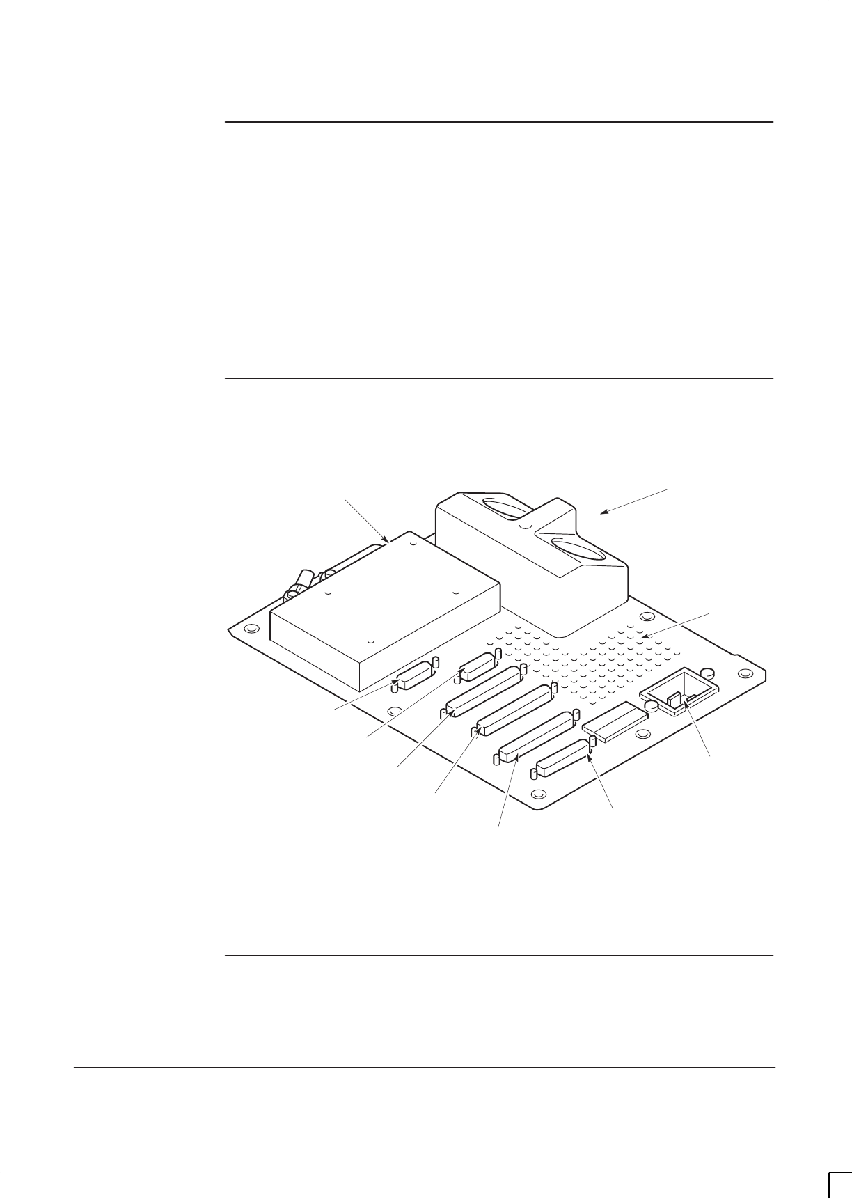
GSM-205-323 Cage backplane interface panel harness assembly (CBIA)
31st Oct 01
Technical Description: Horizon
macro
indoor
68P02902W07-B
CONTROLLED INTRODUCTION
Tech. 2–11
Interface panel
function
The interface panel provides all connection points to:
SThe required power sources.
SExternal alarms (for example battery backup system alarms)
SConnection points to all telecommunications links.
All connectors are linked to the backplane via the CBIA harness. Plastic
connector covers, supplied by Motorola, keep unused connectors protected
from damage by static or foreign matter and should be retained.
Interface panel
diagram
Figure 2-9 shows the locations of the interface panel connectors.
ig.239.rh
T43/BIB
AC POWER
SOCKET INPUT
DC POWER
INPUT
GPS
(if fitted)
CCB
PIX 0
EXTERNAL ALARMS
PIX 1
ICS
VENTILATION
GRID
Figure 2-9 Interface panel connector locations
Interface panel
pinouts
Interface panel pinouts are detailed in
Installation and Configuration:
(GSM-205-423)
Interface panel cabling of this service manual.
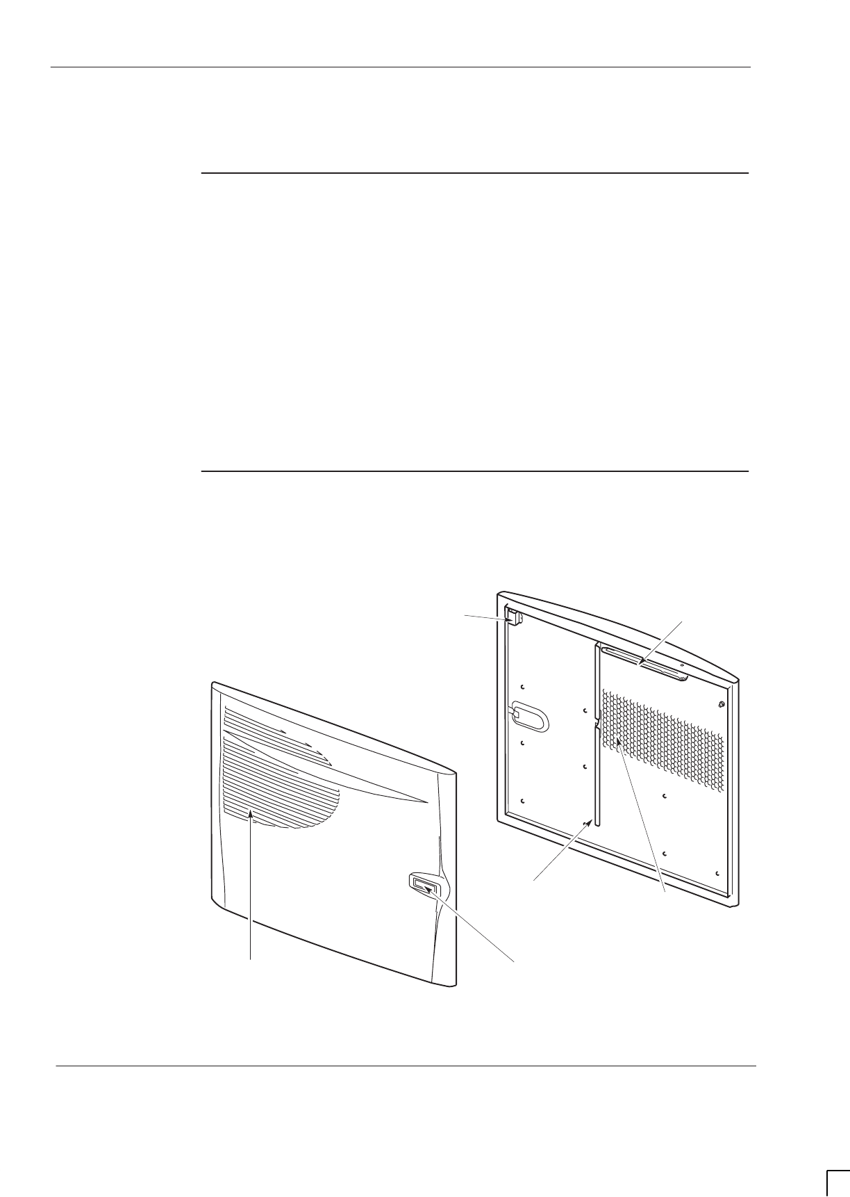
GSM-205-323
Cabinet door and optional hood
31st Oct 01
Tech. 2–12
Technical Description: Horizon
macro
indoor
CONTROLLED INTRODUCTION
68P02902W07-B
Cabinet door and optional hood
Door function
The cabinet is fitted with a door and a hood option. The optional hood cannot
be fitted in conjuction with a stacking bracket.
The door has the following functions:
SProtects modules from damage.
SEnsures correct air ventilation.
SProvides EMC shielding.
The door has a ventilation grid with internal honeycomb grid, a vertical
aluminium air baffle, and a horizontal door stop bracket. The door stop bracket
enables the door to open to 95 or 130 degrees.
The lock is a trigger latch, opened (if unlocked) by pressing the middle button.
There is also a door alarm bracket, to touch the cabinet door switch.
Door external
and internal
view
Figure 2-10 shows both sides of the cabinet door.
ig.266.rh
VENTILATION
GRID
EXTERNAL VIEW
TRIGGER
LATCH
INTERNAL VIEW
VERTICAL AIR
BAFFLE
DOOR ALARM
BRACKET
HONEYCOMB
VENTILATION
DOOR STOP
BRACKET
Figure 2-10 External and internal view of cabinet door
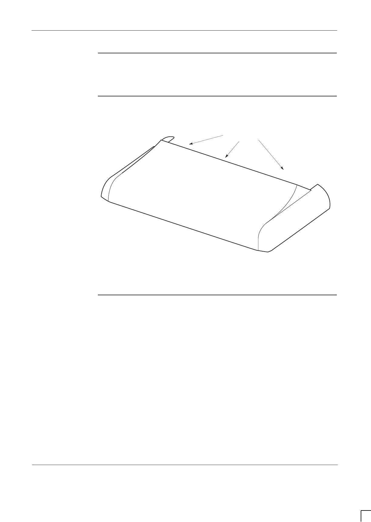
GSM-205-323 Cabinet door and optional hood
31st Oct 01
Technical Description: Horizon
macro
indoor
68P02902W07-B
CONTROLLED INTRODUCTION
Tech. 2–13
Hood function
The optional hood can be fitted to keep unsightly cables and connectors out of
view, where this is important.
View of hood
Figure 2-11 shows a top view of the hood.
LIFTING EDGE
ig.267.rh
Figure 2-11 View of hood as seen from the front of the cabinet
Securing pins
and hood
removal
The hood mounts on four pins that screw into the cabinet top panel, replacing
existing screws.
The hood can be easily lifted off the cabinet by pulling on the lifting edge at the
rear, as shown in Figure 2-11.
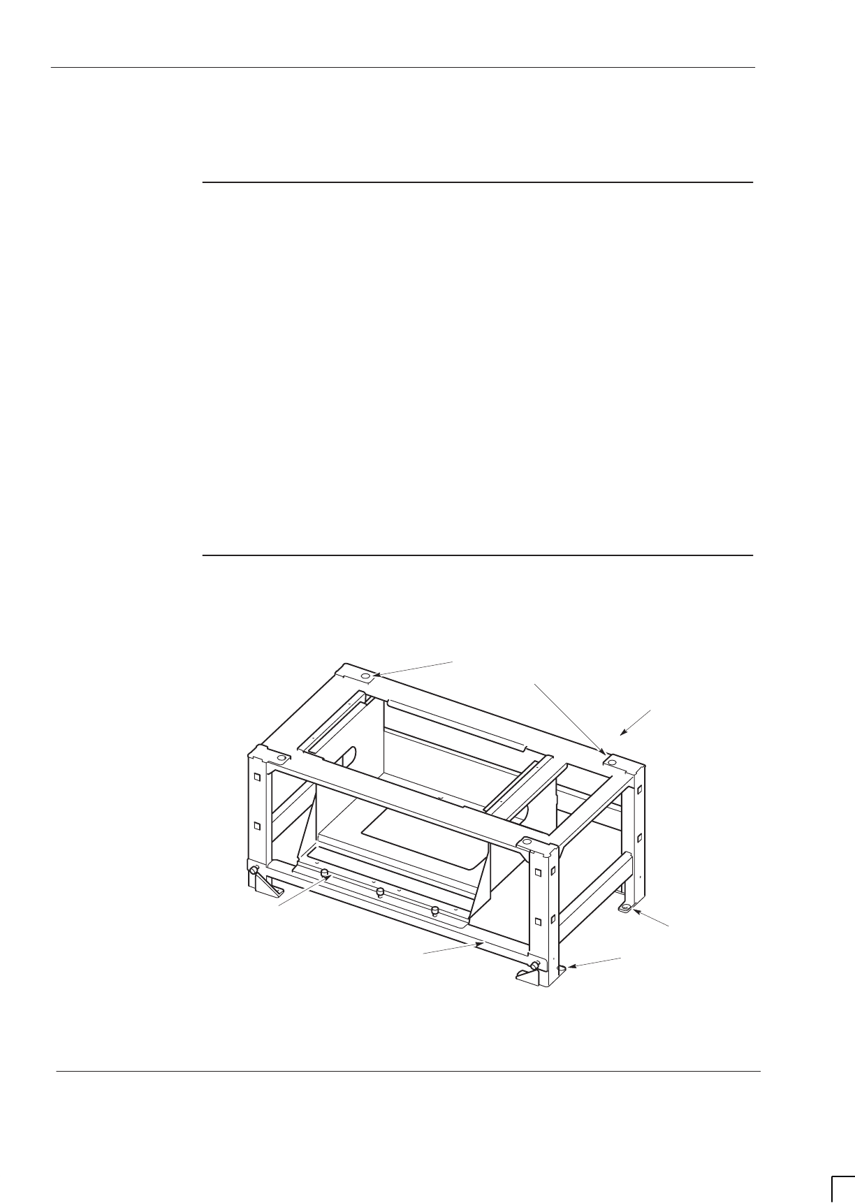
GSM-205-323
Stacking bracket and CCB basket
31st Oct 01
Tech. 2–14
Technical Description: Horizon
macro
indoor
CONTROLLED INTRODUCTION
68P02902W07-B
Stacking bracket and CCB basket
Stacking
bracket function
The stacking bracket has two main functions:
STo enable a second cabinet to be stacked on top of the first cabinet.
STo house CCBs in a dedicated optional CCB basket.
The stacking bracket is fixed to the top of the cabinet by eight M8 screws. If the
stacking bracket is replacing an existing hood, then the four hood securing pins
must first be removed to accommodate four of the stacking bracket screws. A
second cabinet may be attached on top of the stacking bracket by four M10
screws.
Lower cabinet outlet and additional upper cabinet inlet ventilation is provided by
the large open sides of the stacking bracket (especially on the right side of the
cabinet).
The CCB basket is fitted only if CCBs are required. The CCB basket is
removable, to enable access for SURF module replacement.
Stacking
bracket diagram
Figure 2-12 shows a view of the stacking bracket with CCB basket installed.
ig.268.rh
M8 HOLES (8) FOR
BOTTOM CABINET
ATTACHMENT.
M10 HOLES (4) FOR TOP CABINET
ATTACHMENT (IF REQUIRED)
CCB BASKET
(IF REQUIRED)
DETACHABLE
CCB BASKET BAR
REAR OF
BRACKET
Figure 2-12 View of stacking bracket with CCB basket installed.
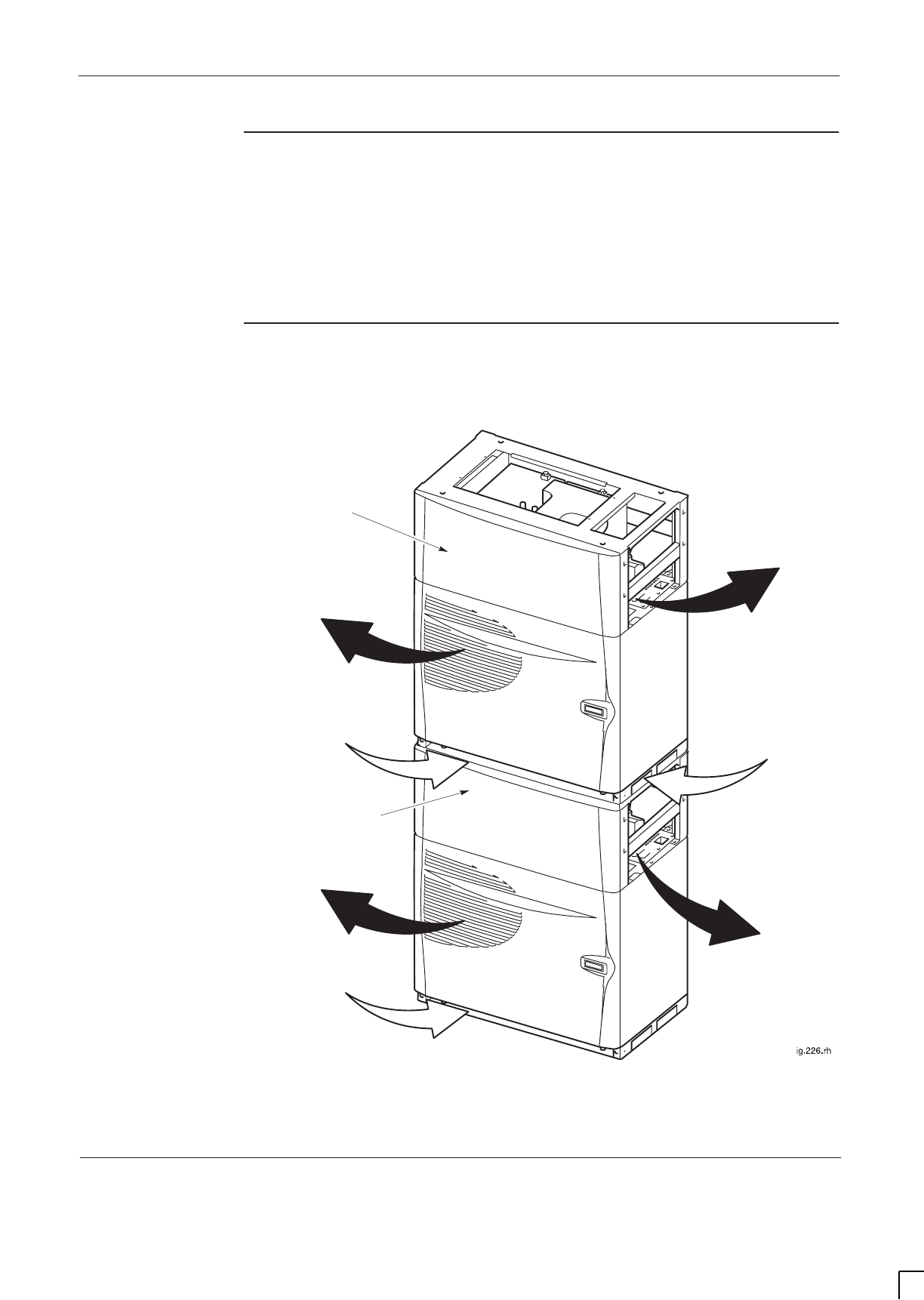
GSM-205-323 Stacking bracket and CCB basket
31st Oct 01
Technical Description: Horizon
macro
indoor
68P02902W07-B
CONTROLLED INTRODUCTION
Tech. 2–15
Stacking
bracket front
cover function
The stacking bracket front cover clips onto the front of the stacking bracket and
provides the following functions:
SProtection for CCB (if fitted).
SBlanking panel to match appearance of cabinet door.
View of stacked
cabinets
Figure 2-13 shows a view of two stacked Horizon
macro
indoor cabinets with
front covers attached to the two stacking brackets.
Inlet air
Inlet air
Stacking bracket
front cover
Inlet air
Outlet air
Outlet air
Outlet air
Outlet air
Stacking bracket
front cover
Figure 2-13 View of two stacked Horizon
macro
indoor cabinets, showing
stacking bracket front covers

GSM-205-323
Stacking bracket and CCB basket
31st Oct 01
Tech. 2–16
Technical Description: Horizon
macro
indoor
CONTROLLED INTRODUCTION
68P02902W07-B

31st Oct 01
Technical Description: Horizon
macro
indoor
68P02902W07-B
CONTROLLED INTRODUCTION
i
Chapter 3
Temperature control system

GSM-205-323
31st Oct 01
ii
Technical Description: Horizon
macro
indoor
CONTROLLED INTRODUCTION
68P02902W07-B

GSM-205-323
31st Oct 01
Technical Description: Horizon
macro
indoor
68P02902W07-B
CONTROLLED INTRODUCTION
iii
Chapter 3
Temperature control system i. . . . . . . . . . . . . . . . . . . . . . . . . . . . . . . . . . .
Indoor temperature control system Tech. 3–1. . . . . . . . . . . . . . . . . . . . . . . . . . . . . . . . . . . . .
Temperature control overview Tech. 3–1. . . . . . . . . . . . . . . . . . . . . . . . . . . . . . . . . . . .
Cabinet over temperature control Tech. 3–1. . . . . . . . . . . . . . . . . . . . . . . . . . . . . . . . .
Temperature sensors Tech. 3–1. . . . . . . . . . . . . . . . . . . . . . . . . . . . . . . . . . . . . . . . . . .
Cabinet restart after shutdown Tech. 3–1. . . . . . . . . . . . . . . . . . . . . . . . . . . . . . . . . . . .
Fan unit description Tech. 3–2. . . . . . . . . . . . . . . . . . . . . . . . . . . . . . . . . . . . . . . . . . . . . . . . . .
Fan unit overview Tech. 3–2. . . . . . . . . . . . . . . . . . . . . . . . . . . . . . . . . . . . . . . . . . . . . . .
Fan operation and reset Tech. 3–2. . . . . . . . . . . . . . . . . . . . . . . . . . . . . . . . . . . . . . . . .
Filter option and effect on fans Tech. 3–2. . . . . . . . . . . . . . . . . . . . . . . . . . . . . . . . . . . .

GSM-205-323
31st Oct 01
iv
Technical Description: Horizon
macro
indoor
CONTROLLED INTRODUCTION
68P02902W07-B

GSM-205-323 Indoor temperature control system
31st Oct 01
Technical Description: Horizon
macro
indoor
68P02902W07-B
CONTROLLED INTRODUCTION
Tech. 3–1
Indoor temperature control system
Temperature
control
overview
The Horizon
macro
indoor cabinet contains equipment that has to be maintained
within the operational temperature range, to ensure correct operation of the
equipment and to guard against premature failure of the individual components.
The internal temperature is maintained within these limits by internal fans.
Cabinet over
temperature
control
Under overheat conditions, as the temperature rises above preset levels,
temperature sensors located in various areas within the cabinet provide alarms.
A further increase in temperature causes dual sensors, set at a higher threshold
temperature to initiate PSM and cabinet shutdown. The cabinet is restarted
when the sensors are reset by a substantial fall in temperature.
The CTUs have their own shutdown responses to overheating. The CTUs
shutdown at 92 _C.
850/900 MHz CTUs also have an internal 4 dB power reduction response to
overheating at 85 _C. 1800/1900 MHz CTUs have a 0.6 dB cut back at 70 _C, in
addition to the 4 dB power reduction at 85 _C.
The CTU shutdown response to overheating provides a second level of cabinet
protection, independent of the cabinet heat sensors.
Temperature
sensors
The three cabinet temperature sensors are located above the CTU
compartment (see Figure 2-7) and consist of the following:
SOne 70 _C sensor provides a cabinet overtemperature alarm when the
cabinet temperature exceeds planned level. The alarm is processed by
the alarm board and MCUF, and sent on to the OMC-R via the BSC.
STwo 85 _C sensors shut down the PSMs to protect the cabinet equipment
from heat damage. Both sensors must detect excess temperature for the
shutdown to take place; this reduces the risk of an unnecessary shutdown.
No prior notification of shutdown is given to the OMC-R, except for the
original 70 _C sensor alarm. This is because the MCUF and CTUs
immediately lose power and functionality.
Cabinet restart
after shutdown
The cabinet is restarted when the overtemperature condition initiating shutdown
has reset. The two 85 _C temperature sensors reset at 55 _C. This
re-establishes an earth point for the PSM internal detectors connected to the
cabinet heat sensors, which then reactivate the PSM outputs. The MCUF then
reboots as in a normal power up.
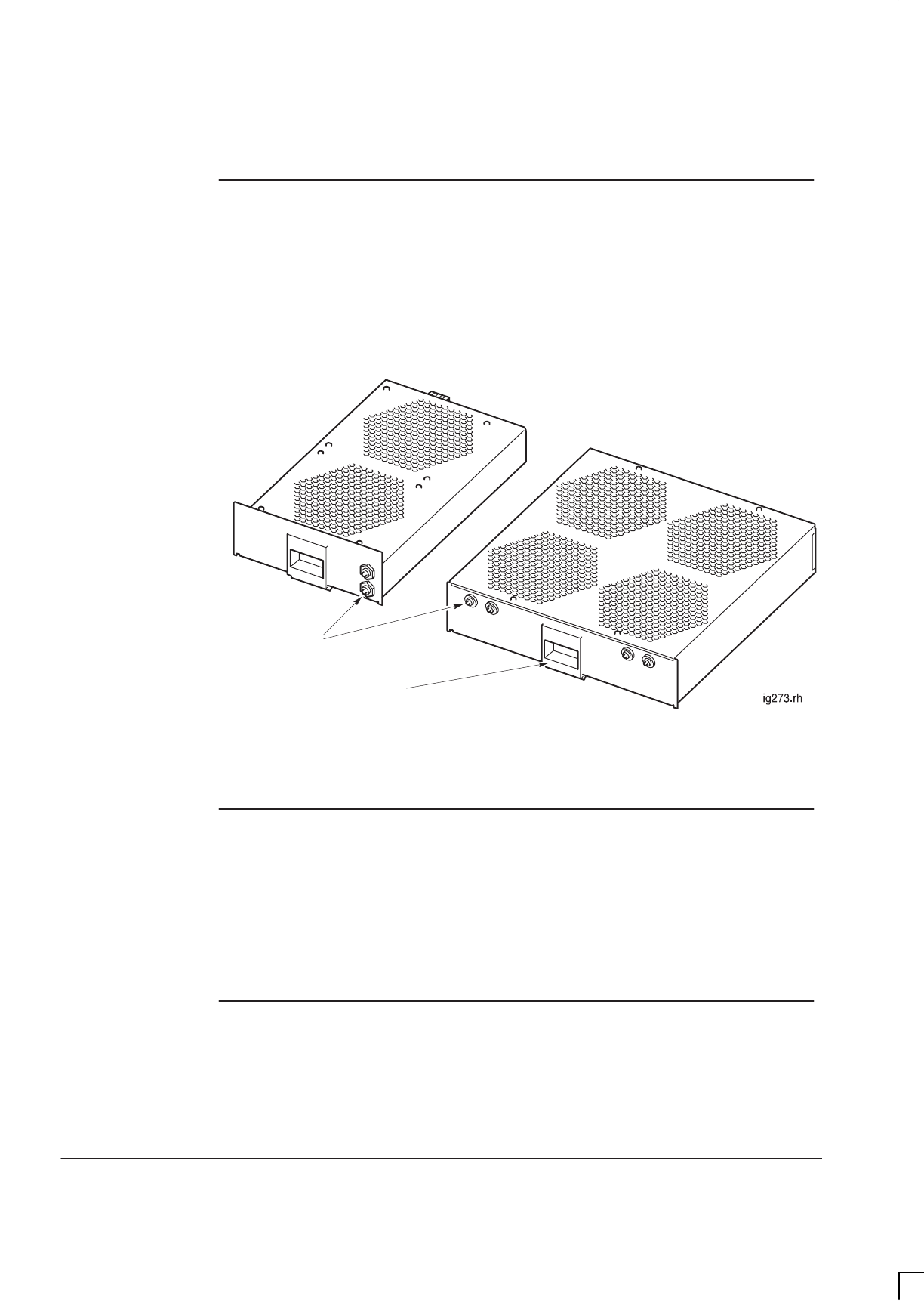
GSM-205-323
Fan unit description
31st Oct 01
Tech. 3–2
Technical Description: Horizon
macro
indoor
CONTROLLED INTRODUCTION
68P02902W07-B
Fan unit description
Fan unit
overview
The indoor cabinet operating temperature is maintained by three sets of fans:
SOne 4-fan unit (referred to as FAN0), located in front and beneath the
digital module shelf.
STwo identical 2-fan units, (referred to as FAN1 and FAN2), located
beneath the CTUs.
Figure 3-1 shows the two types of fan unit:
RESET BUTTONS
(ONE PER FAN)
2-FAN
UNIT
4-FAN
UNIT
SLIDE LATCH FOR
MODULE REMOVAL
Figure 3-1 View of 2-fan and 4-fan units
Fan operation
and reset
The fans draw in air from beneath the cabinet, and the air is expelled through
the door and top cabinet vents. The fans run continuously, and respond to
temperature changes to ensure adequate flow. The speed of each fan is
controlled by a heat sensor mounted on the fan hub.
Each fan has a reset button, for use if a fan has stopped or cannot start. Each
reset button is marked FRONT or REAR to identify the appropriate fan.
Filter option
and effect on
fans
The filter is an option and not essential in a clean environment. The single filter
is mounted under all the fan units. If clogged, fan airflow may be reduced,
straining fan motors and increasing fan noise.

31st Oct 01
Technical Description: Horizon
macro
indoor
68P02902W07-B
CONTROLLED INTRODUCTION
i
Chapter 4
Cabinet power supply

GSM-205-323
31st Oct 01
ii
Technical Description: Horizon
macro
indoor
CONTROLLED INTRODUCTION
68P02902W07-B

GSM-205-323
31st Oct 01
Technical Description: Horizon
macro
indoor
68P02902W07-B
CONTROLLED INTRODUCTION
iii
Chapter 4
Cabinet power supply i. . . . . . . . . . . . . . . . . . . . . . . . . . . . . . . . . . . . . . . . .
Horizonmacro indoor power supplies Tech. 4–1. . . . . . . . . . . . . . . . . . . . . . . . . . . . . . . . . . .
Power supply overview Tech. 4–1. . . . . . . . . . . . . . . . . . . . . . . . . . . . . . . . . . . . . . . . . .
Location of power modules Tech. 4–1. . . . . . . . . . . . . . . . . . . . . . . . . . . . . . . . . . . . . . .
Power supply module (PSM) Tech. 4–2. . . . . . . . . . . . . . . . . . . . . . . . . . . . . . . . . . . . . . . . . .
Types and overview of PSM Tech. 4–2. . . . . . . . . . . . . . . . . . . . . . . . . . . . . . . . . . . . . .
PSM location and redundancy Tech. 4–3. . . . . . . . . . . . . . . . . . . . . . . . . . . . . . . . . . . .
PSM module view Tech. 4–3. . . . . . . . . . . . . . . . . . . . . . . . . . . . . . . . . . . . . . . . . . . . . . .
PSM alarms Tech. 4–4. . . . . . . . . . . . . . . . . . . . . . . . . . . . . . . . . . . . . . . . . . . . . . . . . . . .
PSM LEDs Tech. 4–4. . . . . . . . . . . . . . . . . . . . . . . . . . . . . . . . . . . . . . . . . . . . . . . . . . . . .
PSM backplane protection Tech. 4–4. . . . . . . . . . . . . . . . . . . . . . . . . . . . . . . . . . . . . . .
Hold-up battery module Tech. 4–5. . . . . . . . . . . . . . . . . . . . . . . . . . . . . . . . . . . . . . . . . . . . . . .
Introduction to hold-up battery module Tech. 4–5. . . . . . . . . . . . . . . . . . . . . . . . . . . . .
Specifications Tech. 4–6. . . . . . . . . . . . . . . . . . . . . . . . . . . . . . . . . . . . . . . . . . . . . . . . . .
Front panel switch and LEDs Tech. 4–7. . . . . . . . . . . . . . . . . . . . . . . . . . . . . . . . . . . . .
Hold-up module batteries Tech. 4–7. . . . . . . . . . . . . . . . . . . . . . . . . . . . . . . . . . . . . . . .
Functional description Tech. 4–8. . . . . . . . . . . . . . . . . . . . . . . . . . . . . . . . . . . . . . . . . . .
Hold-up battery module functional diagram Tech. 4–8. . . . . . . . . . . . . . . . . . . . . . . . .
Alarms Tech. 4–9. . . . . . . . . . . . . . . . . . . . . . . . . . . . . . . . . . . . . . . . . . . . . . . . . . . . . . . . .
Signals Tech. 4–9. . . . . . . . . . . . . . . . . . . . . . . . . . . . . . . . . . . . . . . . . . . . . . . . . . . . . . . .
Circuit breaker module (CBM) Tech. 4–10. . . . . . . . . . . . . . . . . . . . . . . . . . . . . . . . . . . . . . . . .
CBM overview Tech. 4–10. . . . . . . . . . . . . . . . . . . . . . . . . . . . . . . . . . . . . . . . . . . . . . . . . .
View of CBM Tech. 4–10. . . . . . . . . . . . . . . . . . . . . . . . . . . . . . . . . . . . . . . . . . . . . . . . . . .
Operation of CBM Tech. 4–11. . . . . . . . . . . . . . . . . . . . . . . . . . . . . . . . . . . . . . . . . . . . . . .
MicroBCU Power Supply Module (BPSM) Tech. 4–12. . . . . . . . . . . . . . . . . . . . . . . . . . . . . . .
Introduction to BPSM Tech. 4–12. . . . . . . . . . . . . . . . . . . . . . . . . . . . . . . . . . . . . . . . . . . .
BPSM diagram Tech. 4–12. . . . . . . . . . . . . . . . . . . . . . . . . . . . . . . . . . . . . . . . . . . . . . . . .
Functional description Tech. 4–13. . . . . . . . . . . . . . . . . . . . . . . . . . . . . . . . . . . . . . . . . . .

GSM-205-323
31st Oct 01
iv
Technical Description: Horizon
macro
indoor
CONTROLLED INTRODUCTION
68P02902W07-B
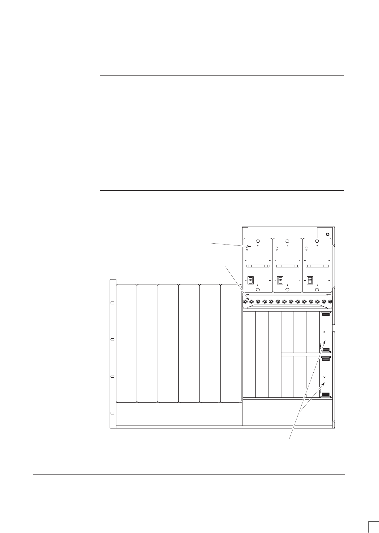
GSM-205-323 Horizonmacro indoor power supplies
31st Oct 01
Technical Description: Horizon
macro
indoor
68P02902W07-B
CONTROLLED INTRODUCTION
Tech. 4–1
Horizon
macro
indoor power supplies
Power supply
overview
The horizon
macro
indoor power supplies consist of the following elements:
SThe power supply modules (PSM):
– +27 V dc PSM (negative earth input).
– –48/60 V dc PSM (positive earth input).
– 120/240 V ac (nominal) PSM.
SThe hold-up battery module.
SThe circuit breaker module (CBM).
SThe mBCU power supply module (BPSM).
Location of
power modules
Figure 4-1 shows the CBIA with the power modules indicated.
BPSMs
PSM or HOLD-UP
BATTERY
MODULE
CBM
Figure 4-1 Location of power modules

GSM-205-323
Power supply module (PSM)
31st Oct 01
Tech. 4–2
Technical Description: Horizon
macro
indoor
CONTROLLED INTRODUCTION
68P02902W07-B
Power supply module (PSM)
Types and
overview of
PSM
There are two types of dc power supply modules (PSMs):
SNominal +27 V (negative earth input).
SNominal –48 V (positive earth input).
There is one type of ac PSM:
SNominal 120/240 V.
All PSMs have the same external appearance and are located in the same
positions. Different types are identified only by front panel labels.
The PSMs are fed from a backplane connector and use pulse width modulation
to generate output supply. A front panel switch (shown in Figure 4-2), disables
the output, reducing the input current as shown in Table 4-1.
Table 4-1 Input currents for power supply module
Type of PSM Output voltage
full load Input current
full load Input load
when output
switch off
+27 V nominal dc +27 V 32 A 1 A
–48 V nominal dc +27 V 18 A 0.5 A
120/240 V nominal ac +27 V 3.75 A 0.1 A
NOTE There are several manufacturers of the PSMs. Each is
fully compatible with the same type of PSM of a different
manufacturer.
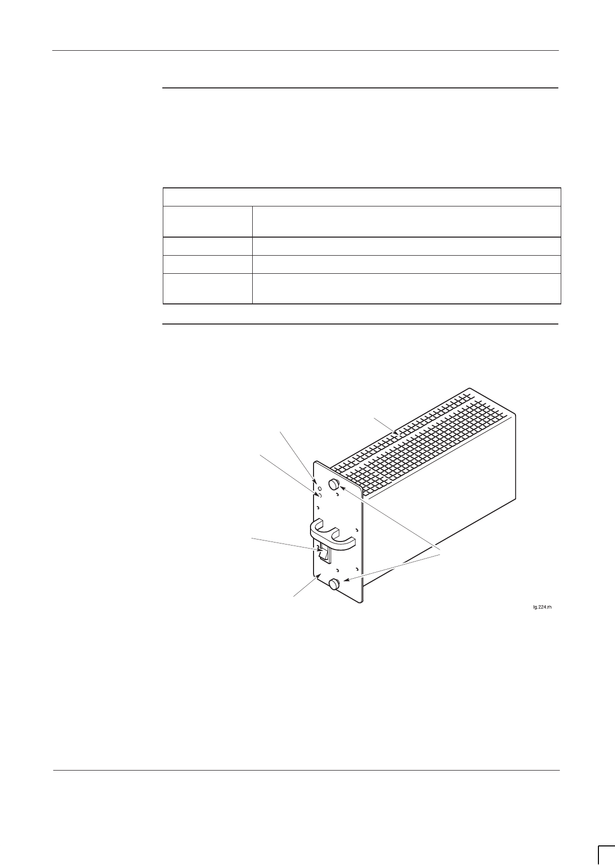
GSM-205-323 Power supply module (PSM)
31st Oct 01
Technical Description: Horizon
macro
indoor
68P02902W07-B
CONTROLLED INTRODUCTION
Tech. 4–3
PSM location
and redundancy
The PSMs are located above the digital cage and circuit breaker module. There
are three slots, two for maximum cabinet configuration, one for redundancy.
Table 4-2 shows the recommended number of PSMs for different operational
configurations.
Table 4-2 PSM operational configurations
Number of
PSMs fitted Maximum load capability
1Complete operation of cabinet for up to three CTUs.
2Complete operation of cabinet for up to six CTUs.
3Redundancy and power load sharing (further enhancing
reliability by reducing temperature of operation).
PSM module
view
Figure 4-2 shows a view of the PSM with LEDs identified.
PSM FRONT PANEL
AIR VENTS ON
ENTIRE TOP AND
BOTTOM PANELS
GREEN LED
ACTIVE
RED LED
ALARM
OUTPUT DISABLE
SWITCH
M4 MODULE ATTACHMENT
SCREWS
Figure 4-2 View of PSM with LEDs identified

GSM-205-323
Power supply module (PSM)
31st Oct 01
Tech. 4–4
Technical Description: Horizon
macro
indoor
CONTROLLED INTRODUCTION
68P02902W07-B
PSM alarms
There are three alarms for each PSM, indicated by LEDs (see Table 4-3):
SOutput fail.
SInput fail.
SOvertemperature.
PSM LEDs
The LEDs function with the properties shown in Table 4-3.
Table 4-3 Power supply module LEDs function
Green LED
ACTIVE Red LED
ALARM Indication
OFF OFF 1. Cabinet power supply off, or
2. Module not connected.
ON OFF Normal operation.
OFF ON 1. Output disable switch off, or
2. Alarm condition with module unable to supply
power.
ON ON Internal problem (such as over temperature), but
still able to maintain supply.
PSM backplane
protection
If a power track on the backplane is broken or short-circuited, the PSM detects
the fault and shuts down to prevent further damage.
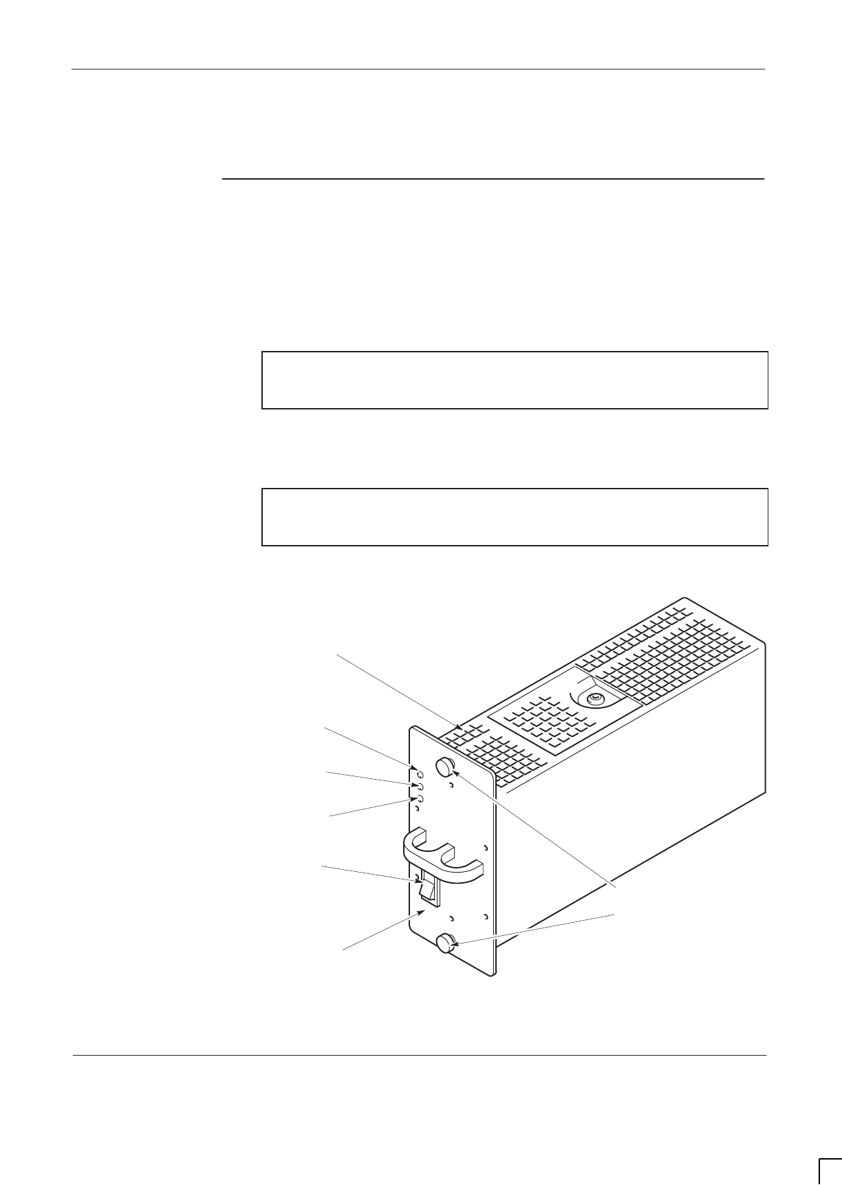
GSM-205-323 Hold-up battery module
31st Oct 01
Technical Description: Horizon
macro
indoor
68P02902W07-B
CONTROLLED INTRODUCTION
Tech. 4–5
Hold-up battery module
Introduction to
hold-up battery
module
The optional hold-up battery module provides short term backup power for one
ac powered Horizon
macro
indoor BTS cabinet. The hold-up battery module is
fitted in the PSM shelf within the CBIA main cage, in any empty slot or in place
of the redundant PSM. It connects to the Horizon
macro
indoor BTS through the
PSM slot backplane connector.
NOTE If the hold-up battery module is used in a Horizon
macro
cabinet with more than three radios fitted, power supply
redundancy cannot be supported.
Under normal operating conditions the hold-up batteries provide ten seconds of
backup power (at 25 _C) for a fully populated (six radio) Horizon
macro
indoor
BTS cabinet.
NOTE Due to the discharge characteristics of the internal
batteries, hold-up duration is reduced at temperatures
below 25 _C.
Figure 4-3 shows a view of the hold-up battery module, with LEDs identified.
ig.223.rh
FRONT PANEL
AIR VENTS ON
ENTIRE TOP AND
BOTTOM PANELS
GREEN LED
ACTIVE
RED LED
ALARM
OUTPUT
ENABLE SWITCH
M4 MODULE ATTACHMENT
SCREWS
GREEN LED
CHARGE
Figure 4-3 View of the hold-up battery module

GSM-205-323
Hold-up battery module
31st Oct 01
Tech. 4–6
Technical Description: Horizon
macro
indoor
CONTROLLED INTRODUCTION
68P02902W07-B
Specifications
Table 4-4 shows the hold-up battery module specifications.
Table 4-4 Hold-up battery module specifications
Weight 5.9 kg
Environmental limits –5 to +45 _C
(indoor only)
Nominal input voltage and
frequency 100 to 240 V ac
50 to 60 Hz
Supply voltage and frequency
range 88 to 270 V ac
45 to 66 Hz
Nominal output voltage 24 V dc
Output voltage range 27.5 0.25 V dc (max)
19 0.25 V dc (min)
Maximum output power 1500 watts
Battery capacity 5 Ah
Recharge time < 2 hours (from LVD level)
Response time (from external
supply failure to battery operation) < 10 msec
Back up switching voltage 88 volts (110 V ac nominal systems)
150 volts (230 V ac nominal systems)
Typical output power duration
(six radios) 10 Seconds
(@ 25 _C)
Expected battery life (standby) 3 to 5 years
py(y)
Expected battery life (discharge)
y
1200 cycles
NOTE This specification is valid up to 3 km altitude,
corresponding to an atmospheric pressure of
approximately 70 kPa (648 to 1048 millibars).

GSM-205-323 Hold-up battery module
31st Oct 01
Technical Description: Horizon
macro
indoor
68P02902W07-B
CONTROLLED INTRODUCTION
Tech. 4–7
Front panel
switch and
LEDs
Front panel enable switch
The rocker style switch mounted on the front panel is used to enable the output
of the hold-up module.
Front panel LED indicators
The front panel LEDs function as follows:
SACTIVE (green).
Normally lit, this LED indicates that the module is capable of powering
cabinets. The ACTIVE LED flashes during discharge.
SALARM (red).
Normally unlit, when lit continuously this LED indicates one or more of the
following alarm conditions exists:
– Battery charger fail.
– Input voltage drops below 88 V ac (110 V systems)
or below 150 V ac (230 V systems).
– Enable fail, the module is not receiving an enable signal from the
Horizon
macro
backplane.
When the ALARM LED is flashing the batteries have failed and are not
capable of providing sufficient energy to supply a ten second hold-up.
NOTE If a battery failure occurs, the batteries may have reached
the end of life. The hold-up battery module is disabled and
must be returned to Motorola for repair.
SCHARGE (green).
The CHARGE LED is lit while batteries are charging.
Hold-up module
batteries
The hold-up module contains two 12 V batteries connected in series to provide
a nominal output of 24 V dc, with a capacity of 5 Ah.
Input protection is provided by a 3.15 A fuse mounted on the battery charger
PCB, this fuse is not user replaceable. The hold-up module must be returned to
Motorola for repair.
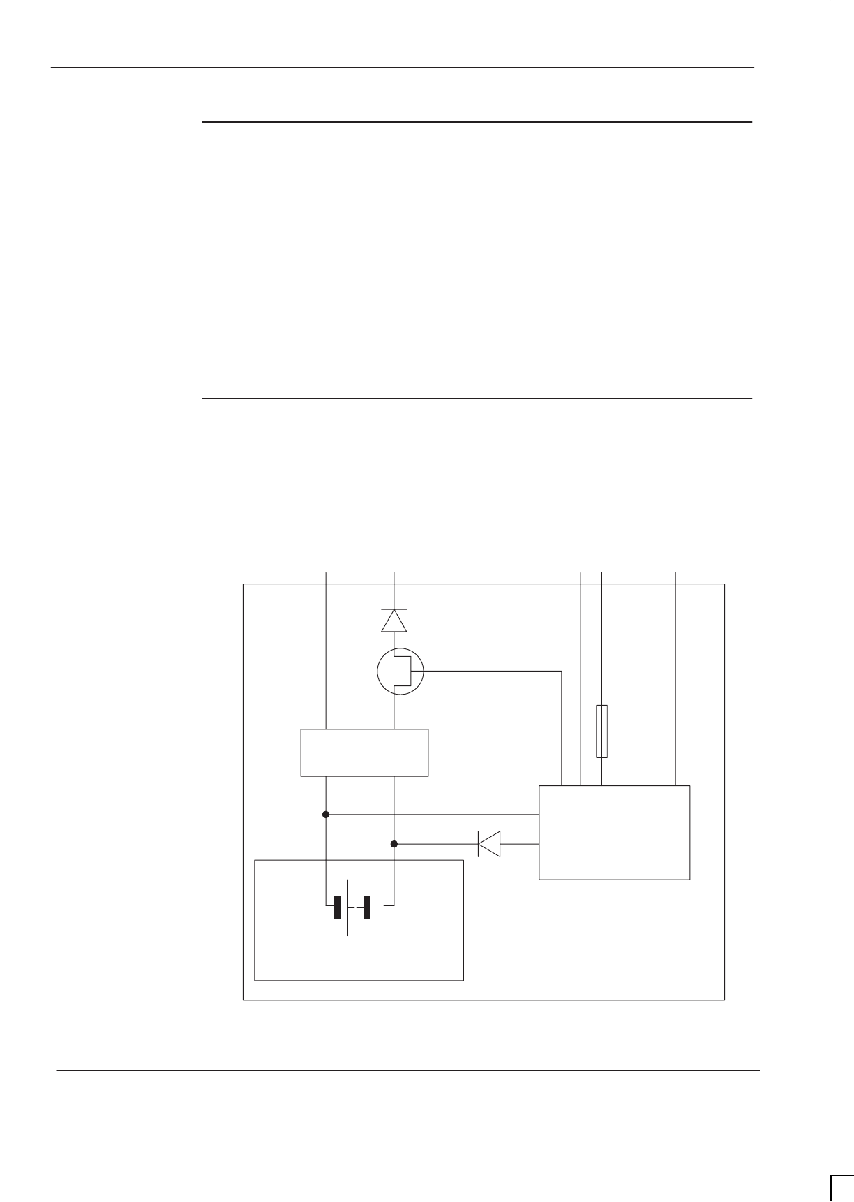
GSM-205-323
Hold-up battery module
31st Oct 01
Tech. 4–8
Technical Description: Horizon
macro
indoor
CONTROLLED INTRODUCTION
68P02902W07-B
Functional
description
During normal operation the batteries are charged by an internal battery
charger. The charger provides battery temperature compensation to protect the
batteries. In the case of external ac power supply failure, the unit automatically
switches the BTS to battery operation. The hold-up battery module indicates
failure alarms to the OMC-R, through the Horizon
macro
alarm board.
Low voltage disconnect (LVD)
The hold-up battery module has an LVD function to protect the batteries from
deep discharge. The battery does not discharge when not in the system or after
operation of the low voltage disconnect.
Hold-up battery
module
functional
diagram
Figure 4-4 shows the electrical layout of the hold-up battery module.
2 12 V
LEAD ACID BATTERIES
LVD
BATTERY
CHARGER AND
INPUT POWER
DETECT
Transistor
switch
To backplane
dc bus
19 to 27.5 V
External
supply
88 to 270 V ac Enable
Fuse
Input
detect
Figure 4-4 Hold-up battery module electrical layout

GSM-205-323 Hold-up battery module
31st Oct 01
Technical Description: Horizon
macro
indoor
68P02902W07-B
CONTROLLED INTRODUCTION
Tech. 4–9
Alarms
Alarms are generated by the open contacts of de-energized relays within the
hold-up battery module, (during normal operation the relays are energized and
the contacts closed). The contacts are rated for 1 A at 30 V. The alarms are
then passed to the Horizon
macro
alarm board, through the CBIA backplane, for
onward transmission to the OMC-R. These alarms are equivalent to the PSM
alarms.
The alarm signals generated are:
SOutput fail.
This alarm is triggered if:
– The enable pin is not correctly plugged into the backplane.
– The battery charger fails.
– The front panel enable switch is off.
– The batteries fail.
NOTE If a battery failure occurs, the batteries may have reached
the end of life. The hold-up battery module is disabled and
must be returned to Motorola for repair.
SInput fail.
This alarm is triggered if the external ac supply voltage drops below:
– 88 volts (110 V ac nominal systems).
– 150 volts (230 V ac nominal systems).
SOver temperature.
This alarm is triggered if the hold-up battery module temperature exceeds
50 _C.
Signals
The following signals interface with the Horizon
macro
backplane:
SEnable.
The output of the hold-up battery module is inhibited unless the ENABLE
signal pin is connected to the output return pin through the Horizon
macro
backplane.
SHold-up module ID.
The hold-up module provides a five bit TTL signal to the OMC-R that
allows identification of the hold-up module. This signal is available when
ac is present and during battery discharge and identifies to the OMC-R the
that a battery hold-up module is fitted.
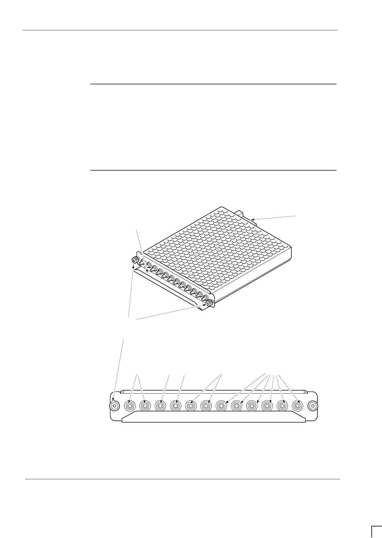
GSM-205-323
Circuit breaker module (CBM)
31st Oct 01
Tech. 4–10
Technical Description: Horizon
macro
indoor
CONTROLLED INTRODUCTION
68P02902W07-B
Circuit breaker module (CBM)
CBM overview
The CBM provides circuit protection and manual isolation for all parts of the
cabinet, except the PSMs. The CBM is located above the digital module shelf
and below the PSMs. The honeycomb casing permits cabinet ventilation
through the module.
The CBM is connected to the backplane, providing isolator switches and
overload protection for the equipment indicated in Figure 4-5.
View of CBM
Figure 4-5 shows views of the CBM with circuit breaker buttons identified.
ig.281.rh
6 CTUs (0 TO 5)
FRONT VIEW
12 A2 A4 A 7 A
BACKPLANE CONNECTOR
M4 MODULE ATTACHMENT
SCREWS
CCB (0 AND 1) SURF FANS BPSMs (A AND B)
7 A
HANDLE-BAFFLE
Figure 4-5 Views of CBM with circuit breaker buttons identified

GSM-205-323 Circuit breaker module (CBM)
31st Oct 01
Technical Description: Horizon
macro
indoor
68P02902W07-B
CONTROLLED INTRODUCTION
Tech. 4–11
Operation of
CBM
Power for each module is supplied via the appropriate circuit breaker switch.
Overload of any circuit results in appropriate front panel circuit breaker button
tripping to the off (out) position. The button can be pressed to the on (in)
position when overload problem has been corrected.
CTUs, BPSMs, CCBs, SURF and fans can be isolated by pressing and
releasing the appropriate button to the off (out) position. Power is restored by
pushing the appropriate button to the on (in) position.
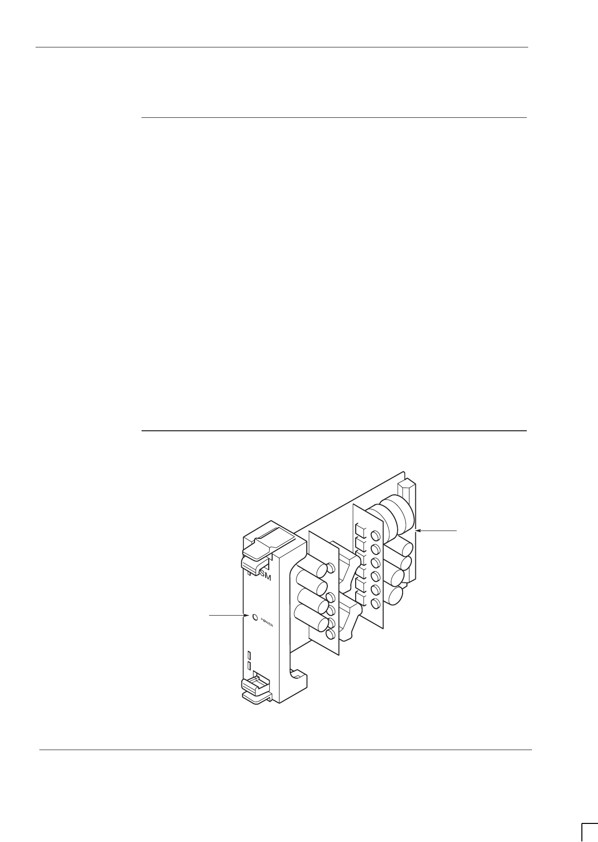
GSM-205-323
MicroBCU Power Supply Module (BPSM)
31st Oct 01
Tech. 4–12
Technical Description: Horizon
macro
indoor
CONTROLLED INTRODUCTION
68P02902W07-B
MicroBCU Power Supply Module (BPSM)
Introduction to
BPSM
This section describes the mBCU power supply module (BPSM). The BPSM,
located in the digital module shelf of the main cage, supplies regulated dc power
to the digital modules.
A single (master) BPSM mounted in the lower half of the digital module shelf
can provide sufficient power for:
SOne MCUF.
SOne FMUX.
STwo NIUs.
SThe alarm module.
An optional second BPSM can be fitted in the upper half of the digital module
shelf to supply any or all of the following:
SBackup power to the alarm module, which is the only digital module
supplied by both BPSMs (for redundancy).
SOptional redundant MCUF and associated FMUX.
SUp to two additional NIUs.
During normal operation, with all the outputs within their regulation limits, a
green LED located on the front panel is illuminated. No alarms are generated
by the BPSM.
BPSM diagram
Figure 4-6 shows a BPSM.
ig.274.rh
BACKPLANE
CONNECTOR
GREEN LED
Figure 4-6 BPSM view
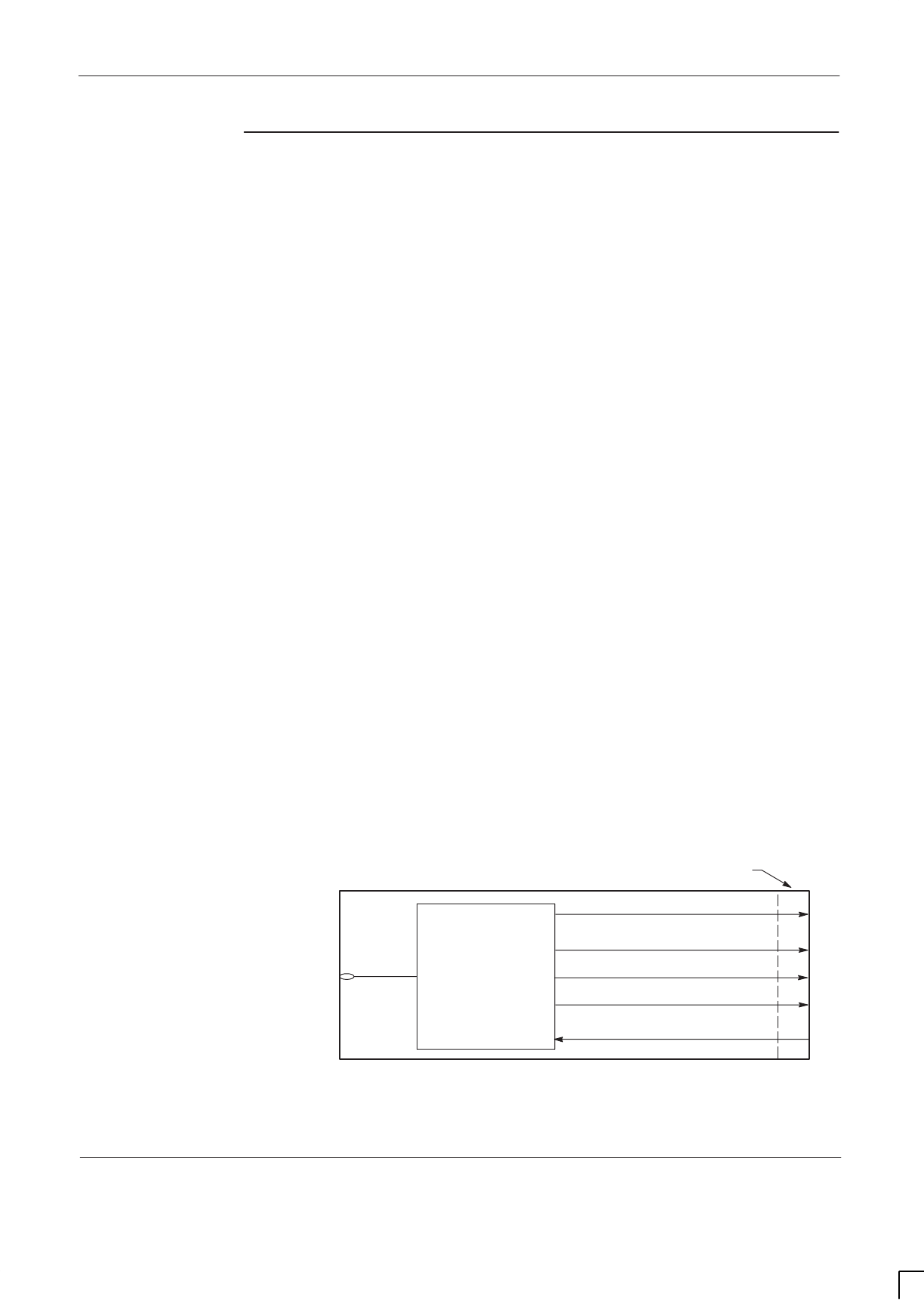
GSM-205-323 MicroBCU Power Supply Module (BPSM)
31st Oct 01
Technical Description: Horizon
macro
indoor
68P02902W07-B
CONTROLLED INTRODUCTION
Tech. 4–13
Functional
description
The BPSM is a switching type dc/dc power converter that converts the cabinet
+27 V dc power to the following regulated dc outputs:
S+3.3 V ±1 % at 10 A (full load current)
S+5 V ±2 % at 10 A (full load current).
S+12 V ±5 % at 4 A (full load current).
S–12 V ±5 % at 2 A (full load current).
Internal BPSM circuits monitor the +3.3 V, +5 V, +12 V and –12 V outputs for the
following purposes:
SOutput voltage regulation.
SOver-voltage protection - provides shutdown if output voltage exceeds 1.1
to 1.2 times the rated output.
SOver-current protection - maximum output current has the following limits:
– 1.1 to 1.8 times full load rating of +3.3 V output.
– 1.1 to 1.8 times full load rating of +5 V output.
– 1.25 to 2 times full load rating of +12 V and –12 V outputs.
Circuit protection
Additional internal circuitry protects the BPSM:
SInput dc reverse polarity protection, achieved by an input series diode.
SThermal protection by automatic BPSM shutdown. Normal BPSM
operation resumes after BPSM temperature returns to a safe level.
SA 10 Amp fuse is located near the backplane connector.
LED display
An active (Green) LED mounted on the front of the BPSM is on when all output
voltages are present and within specified limits. A functional diagram is shown in
Figure 4-7.
ig.275.rh
Green
LED
Power converter and
system monitor
VOUT (+5 V)
VIN (+27 V)
VOUT (+3.3 V)
BACKPLANE CONNECTOR
VOUT (+12 V)
VOUT (–12 V)
Figure 4-7 Functional diagram of BPSM

GSM-205-323
MicroBCU Power Supply Module (BPSM)
31st Oct 01
Tech. 4–14
Technical Description: Horizon
macro
indoor
CONTROLLED INTRODUCTION
68P02902W07-B

31st Oct 01
Technical Description: Horizon
macro
indoor
68P02902W07-B
CONTROLLED INTRODUCTION
i
Chapter 5
RF modules

GSM-205-323
31st Oct 01
ii
Technical Description: Horizon
macro
indoor
CONTROLLED INTRODUCTION
68P02902W07-B

GSM-205-323
31st Oct 01
Technical Description: Horizon
macro
indoor
68P02902W07-B
CONTROLLED INTRODUCTION
iii
Chapter 5
RF modules i. . . . . . . . . . . . . . . . . . . . . . . . . . . . . . . . . . . . . . . . . . . . . . . . . . .
RF equipment detail Tech. 5–1. . . . . . . . . . . . . . . . . . . . . . . . . . . . . . . . . . . . . . . . . . . . . . . . . .
Overview of RF equipment Tech. 5–1. . . . . . . . . . . . . . . . . . . . . . . . . . . . . . . . . . . . . . .
RF specifications Tech. 5–1. . . . . . . . . . . . . . . . . . . . . . . . . . . . . . . . . . . . . . . . . . . . . . .
Receive RF hardware Tech. 5–2. . . . . . . . . . . . . . . . . . . . . . . . . . . . . . . . . . . . . . . . . . .
Transmit (Tx) RF hardware Tech. 5–3. . . . . . . . . . . . . . . . . . . . . . . . . . . . . . . . . . . . . . .
Rx/Tx single antenna duplexing Tech. 5–3. . . . . . . . . . . . . . . . . . . . . . . . . . . . . . . . . . .
RF overview and RF test function Tech. 5–4. . . . . . . . . . . . . . . . . . . . . . . . . . . . . . . . . . . . . .
RF overview Tech. 5–4. . . . . . . . . . . . . . . . . . . . . . . . . . . . . . . . . . . . . . . . . . . . . . . . . . . .
RF main component explanation Tech. 5–4. . . . . . . . . . . . . . . . . . . . . . . . . . . . . . . . . .
RF loopback purpose Tech. 5–5. . . . . . . . . . . . . . . . . . . . . . . . . . . . . . . . . . . . . . . . . . . .
RF loopback hardware Tech. 5–5. . . . . . . . . . . . . . . . . . . . . . . . . . . . . . . . . . . . . . . . . .
RF loopback software operation Tech. 5–5. . . . . . . . . . . . . . . . . . . . . . . . . . . . . . . . . .
Functional diagram of RF Tech. 5–6. . . . . . . . . . . . . . . . . . . . . . . . . . . . . . . . . . . . . . . .
Description of RF test modes Tech. 5–7. . . . . . . . . . . . . . . . . . . . . . . . . . . . . . . . . . . . .
CTU Tech. 5–8. . . . . . . . . . . . . . . . . . . . . . . . . . . . . . . . . . . . . . . . . . . . . . . . . . . . . . . . . . . . . . . .
Overview of CTU Tech. 5–8. . . . . . . . . . . . . . . . . . . . . . . . . . . . . . . . . . . . . . . . . . . . . . .
CTU internal boards Tech. 5–8. . . . . . . . . . . . . . . . . . . . . . . . . . . . . . . . . . . . . . . . . . . . .
Alarm reporting Tech. 5–9. . . . . . . . . . . . . . . . . . . . . . . . . . . . . . . . . . . . . . . . . . . . . . . . .
View of a CTU Tech. 5–10. . . . . . . . . . . . . . . . . . . . . . . . . . . . . . . . . . . . . . . . . . . . . . . . . .
CTU connectors and reset Tech. 5–11. . . . . . . . . . . . . . . . . . . . . . . . . . . . . . . . . . . . . . .
CTU input/output diagram Tech. 5–12. . . . . . . . . . . . . . . . . . . . . . . . . . . . . . . . . . . . . . . .
CTU Tx connector Tech. 5–13. . . . . . . . . . . . . . . . . . . . . . . . . . . . . . . . . . . . . . . . . . . . . .
CTU Rx function Tech. 5–13. . . . . . . . . . . . . . . . . . . . . . . . . . . . . . . . . . . . . . . . . . . . . . . .
CTU Tx function Tech. 5–14. . . . . . . . . . . . . . . . . . . . . . . . . . . . . . . . . . . . . . . . . . . . . . . .
CTU digital processing and control functions Tech. 5–16. . . . . . . . . . . . . . . . . . . . . . .
CTU uplink/downlink Tech. 5–19. . . . . . . . . . . . . . . . . . . . . . . . . . . . . . . . . . . . . . . . . . . .
CTU frequency hopping Tech. 5–20. . . . . . . . . . . . . . . . . . . . . . . . . . . . . . . . . . . . . . . . . . . . . . .
Overview of CTU frequency hopping Tech. 5–20. . . . . . . . . . . . . . . . . . . . . . . . . . . . . .
Synthesizer frequency hopping (SFH) Tech. 5–20. . . . . . . . . . . . . . . . . . . . . . . . . . . . .
SFH example not through BCCH Tech. 5–21. . . . . . . . . . . . . . . . . . . . . . . . . . . . . . . . . .
SFH example hopping through BCCH carrier Tech. 5–21. . . . . . . . . . . . . . . . . . . . . . .
Baseband frequency hopping (BBH) Tech. 5–22. . . . . . . . . . . . . . . . . . . . . . . . . . . . . .
BBH example Tech. 5–22. . . . . . . . . . . . . . . . . . . . . . . . . . . . . . . . . . . . . . . . . . . . . . . . . .
SURF module Tech. 5–24. . . . . . . . . . . . . . . . . . . . . . . . . . . . . . . . . . . . . . . . . . . . . . . . . . . . . . .
SURF module overview Tech. 5–24. . . . . . . . . . . . . . . . . . . . . . . . . . . . . . . . . . . . . . . . . .
Single band SURF module view Tech. 5–25. . . . . . . . . . . . . . . . . . . . . . . . . . . . . . . . . .
Functional description of the single band SURF Tech. 5–26. . . . . . . . . . . . . . . . . . . .
Single band SURF functional diagram Tech. 5–27. . . . . . . . . . . . . . . . . . . . . . . . . . . . .
Dual band SURF module view Tech. 5–28. . . . . . . . . . . . . . . . . . . . . . . . . . . . . . . . . . . .
Functional description of dual band SURF modules Tech. 5–29. . . . . . . . . . . . . . . . .
Dual band SURF functional diagram Tech. 5–30. . . . . . . . . . . . . . . . . . . . . . . . . . . . . .
Tx blocks overview Tech. 5–31. . . . . . . . . . . . . . . . . . . . . . . . . . . . . . . . . . . . . . . . . . . . . . . . . . .
Introduction to transmit blocks Tech. 5–31. . . . . . . . . . . . . . . . . . . . . . . . . . . . . . . . . . . .
Screw retention in Tx block locations Tech. 5–31. . . . . . . . . . . . . . . . . . . . . . . . . . . . . .
View of basket for Tx blocks Tech. 5–32. . . . . . . . . . . . . . . . . . . . . . . . . . . . . . . . . . . . . .
Transmit block connectors Tech. 5–32. . . . . . . . . . . . . . . . . . . . . . . . . . . . . . . . . . . . . . .
View of Tx block connectors Tech. 5–33. . . . . . . . . . . . . . . . . . . . . . . . . . . . . . . . . . . . . .

GSM-205-323
31st Oct 01
iv
Technical Description: Horizon
macro
indoor
CONTROLLED INTRODUCTION
68P02902W07-B
Blanking plate Tech. 5–34. . . . . . . . . . . . . . . . . . . . . . . . . . . . . . . . . . . . . . . . . . . . . . . . . . . . . . .
Purpose of blanking plate Tech. 5–34. . . . . . . . . . . . . . . . . . . . . . . . . . . . . . . . . . . . . . . .
View of blanking plate Tech. 5–34. . . . . . . . . . . . . . . . . . . . . . . . . . . . . . . . . . . . . . . . . . .
Feedthrough plate Tech. 5–35. . . . . . . . . . . . . . . . . . . . . . . . . . . . . . . . . . . . . . . . . . . . . . . . . . .
Purpose of feedthrough plate Tech. 5–35. . . . . . . . . . . . . . . . . . . . . . . . . . . . . . . . . . . . .
View of feedthrough plate Tech. 5–35. . . . . . . . . . . . . . . . . . . . . . . . . . . . . . . . . . . . . . . .
Feedthrough plate connectors Tech. 5–35. . . . . . . . . . . . . . . . . . . . . . . . . . . . . . . . . . . .
HCU plate Tech. 5–36. . . . . . . . . . . . . . . . . . . . . . . . . . . . . . . . . . . . . . . . . . . . . . . . . . . . . . . . . . .
HCU overview Tech. 5–36. . . . . . . . . . . . . . . . . . . . . . . . . . . . . . . . . . . . . . . . . . . . . . . . . .
HCU view Tech. 5–36. . . . . . . . . . . . . . . . . . . . . . . . . . . . . . . . . . . . . . . . . . . . . . . . . . . . . .
HCU functional diagram Tech. 5–36. . . . . . . . . . . . . . . . . . . . . . . . . . . . . . . . . . . . . . . . .
HCU connectors Tech. 5–37. . . . . . . . . . . . . . . . . . . . . . . . . . . . . . . . . . . . . . . . . . . . . . . .
TDF Tech. 5–38. . . . . . . . . . . . . . . . . . . . . . . . . . . . . . . . . . . . . . . . . . . . . . . . . . . . . . . . . . . . . . . .
Overview of TDF Tech. 5–38. . . . . . . . . . . . . . . . . . . . . . . . . . . . . . . . . . . . . . . . . . . . . . . .
TDF view Tech. 5–38. . . . . . . . . . . . . . . . . . . . . . . . . . . . . . . . . . . . . . . . . . . . . . . . . . . . . .
TDF functional diagram Tech. 5–39. . . . . . . . . . . . . . . . . . . . . . . . . . . . . . . . . . . . . . . . . .
TDF connectors Tech. 5–39. . . . . . . . . . . . . . . . . . . . . . . . . . . . . . . . . . . . . . . . . . . . . . . .
Dual band TDF Tech. 5–40. . . . . . . . . . . . . . . . . . . . . . . . . . . . . . . . . . . . . . . . . . . . . . . . . . . . . .
Overview of Dual band TDF Tech. 5–40. . . . . . . . . . . . . . . . . . . . . . . . . . . . . . . . . . . . . .
Dual band TDF view Tech. 5–40. . . . . . . . . . . . . . . . . . . . . . . . . . . . . . . . . . . . . . . . . . . . .
Dual band TDF functional diagram Tech. 5–41. . . . . . . . . . . . . . . . . . . . . . . . . . . . . . . .
Dual band TDF connectors Tech. 5–41. . . . . . . . . . . . . . . . . . . . . . . . . . . . . . . . . . . . . . .
DCF Tech. 5–42. . . . . . . . . . . . . . . . . . . . . . . . . . . . . . . . . . . . . . . . . . . . . . . . . . . . . . . . . . . . . . . .
DCF overview Tech. 5–42. . . . . . . . . . . . . . . . . . . . . . . . . . . . . . . . . . . . . . . . . . . . . . . . . .
DCF view Tech. 5–42. . . . . . . . . . . . . . . . . . . . . . . . . . . . . . . . . . . . . . . . . . . . . . . . . . . . . .
DCF functional diagram Tech. 5–43. . . . . . . . . . . . . . . . . . . . . . . . . . . . . . . . . . . . . . . . . .
DCF connectors Tech. 5–43. . . . . . . . . . . . . . . . . . . . . . . . . . . . . . . . . . . . . . . . . . . . . . . .
DDF Tech. 5–44. . . . . . . . . . . . . . . . . . . . . . . . . . . . . . . . . . . . . . . . . . . . . . . . . . . . . . . . . . . . . . . .
Overview of DDF Tech. 5–44. . . . . . . . . . . . . . . . . . . . . . . . . . . . . . . . . . . . . . . . . . . . . . .
DDF view Tech. 5–44. . . . . . . . . . . . . . . . . . . . . . . . . . . . . . . . . . . . . . . . . . . . . . . . . . . . . .
DDF functional diagram Tech. 5–45. . . . . . . . . . . . . . . . . . . . . . . . . . . . . . . . . . . . . . . . . .
DDF connectors Tech. 5–45. . . . . . . . . . . . . . . . . . . . . . . . . . . . . . . . . . . . . . . . . . . . . . . .
CCB Tech. 5–46. . . . . . . . . . . . . . . . . . . . . . . . . . . . . . . . . . . . . . . . . . . . . . . . . . . . . . . . . . . . . . . .
CCB overview Tech. 5–46. . . . . . . . . . . . . . . . . . . . . . . . . . . . . . . . . . . . . . . . . . . . . . . . . .
CCB control board (TCB) and set switch Tech. 5–46. . . . . . . . . . . . . . . . . . . . . . . . . . .
TCB and link redundancy Tech. 5–46. . . . . . . . . . . . . . . . . . . . . . . . . . . . . . . . . . . . . . . .
CCB view Tech. 5–47. . . . . . . . . . . . . . . . . . . . . . . . . . . . . . . . . . . . . . . . . . . . . . . . . . . . . .
CCB configuration Tech. 5–48. . . . . . . . . . . . . . . . . . . . . . . . . . . . . . . . . . . . . . . . . . . . . .
CCB functional description and diagram Tech. 5–49. . . . . . . . . . . . . . . . . . . . . . . . . . .

GSM-205-323 RF equipment detail
31st Oct 01
Technical Description: Horizon
macro
indoor
68P02902W07-B
CONTROLLED INTRODUCTION
Tech. 5–1
RF equipment detail
Overview of RF
equipment
This chapter describes the functional operation of radio frequency (RF) modules
used in the cabinet. All descriptions are presented at a block diagram level.
RF modules described
The following equipment is described:
SCompact Transceiver Unit (CTU).
SSectorized Universal Receiver Front-end (SURF) module (for receive
path), both single and dual band variants.
SSeveral types of transmit block (Tx block). Tx blocks are used for various
configurations of transmit path, depending on number of antennas, CTUs
and functionality, including potential shared receive path.
SCavity combining block CCB, used to combine three CTU transmit paths in
conditions where Synthesizer Frequency Hopping (SFH) is not required.
Two CCBs can combine up to six CTU transmit paths on to a single Tx
antenna.
RF general information and loopback test function
The following additional information is presented in this chapter:
SGeneral definition of transmit and receive functions in this RF equipment
detail section.
SAn RF overview and RF test function description in the next section.
SAn explanation of CTU frequency hopping in a section immediately after
the CTU section.
These descriptions are intended to assist the reader in understanding the
information on the RF modules.
RF
specifications
All equipment meets or exceeds ETSI regulations. Frequency information is
listed in the Specifications part of this manual.

GSM-205-323
RF equipment detail
31st Oct 01
Tech. 5–2
Technical Description: Horizon
macro
indoor
CONTROLLED INTRODUCTION
68P02902W07-B
Receive RF
hardware
Receiver RF hardware consists of the SURF module and optional Tx block
receive path, and the receive section of the CTU.
The SURF module provides bandpass filtering and low-noise amplification for up
to three sectors, with diversity receive antenna signals, together with switching
to CTUs.
CTU Rx role
The CTU provides the following receive functions:
SReceiver tuning (on a timeslot basis) to any receive channel frequency.
SDemodulation and equalization of the receive channel signal.
SMeasurement of the received signal strength indication (RSSI) and signal
quality.
SRecovery of received data from the demodulated radio channel.
SChannel decoding of the received data and processing of the recovered
signal. Traffic data is passed on to the MCUF for routeing to the MSC.
SDigital interface to the SURF module, which controls selection by the
SURF switch of the receive signals from the appropriate antenna.
SComparison and processing of an additional receive path from a second
diversity antenna input to compensate for multipath fading and
interference.

GSM-205-323 RF equipment detail
31st Oct 01
Technical Description: Horizon
macro
indoor
68P02902W07-B
CONTROLLED INTRODUCTION
Tech. 5–3
Transmit (Tx)
RF hardware
Transmit RF hardware consists of Tx blocks in appropriate combinations to meet
requirements of antenna sharing for the transceivers.
CTU Tx role
The CTU provides the following transmit functions:
STransmit tuning (on a timeslot basis) for generation of any transmit
channel RF frequency.
SEncoding transmit data output.
SDigital modulation of transmit data onto the transmit radio channel signal.
SFinal RF power amplification and output power level control of the transmit
radio channel RF signal.
SWhen using a CCB, the output of control data to the CCB.
SChannel encoding of the data to be transmitted, interleaving signal and
traffic channel data, as defined by ETSI.
Rx/Tx single
antenna
duplexing
Duplexers allow a single antenna to be used for both transmit and receive
operations. Duplexers exist within several of the transmit blocks. Normally
duplexed RF signals are used through one antenna, with a second receive
antenna to provide diversity.
CAUTION If a single antenna (non-diversity) is required, the duplex
antenna RF receive cable from the transmit block must be
connected to the RxA path at the SURF. Simply switching
off diversity at the OMC-R without the correct SURF
configuration will cause a loss of reception.

GSM-205-323
RF overview and RF test function
31st Oct 01
Tech. 5–4
Technical Description: Horizon
macro
indoor
CONTROLLED INTRODUCTION
68P02902W07-B
RF overview and RF test function
RF overview
This section explains the RF functional blocks and additional RF loopback test
capability.
The terminology, functionality and optional capabilities are set out, as a basis for
understanding more detailed descriptions in RF module sections of this chapter.
RF main
component
explanation
The following description should be read in conjunction with Figure 5-1.
The RF equipment consists of three main blocks:
SThe CTU.
SThe SURF module.
SThe Tx block or alternatively CCBs.
CTU
The CTU can operate at 850 MHz, 900 MHz, 1800 MHz or 1900 MHz,
depending on the BTS variant ordered. It can receive two inputs, RxA and RxB,
from the SURF. These inputs are converted into digital voice/data. The two Rx
signals provide diversity of the Rx function from the MS (uplink).
The CTU also generates a Tx data signal, translated from received digital
voice/data, which is transmitted by cable to the Tx block for antenna
transmission to the MS (downlink).
The third (middle) port provides an RF loopback test signal capability, for
automatic transmission of RF test signals to the SURF.
SURF module
One of six variants of the SURF module can be installed in the Horizon
macro
indoor:
SSingle band 850 MHz SURF.
SSingle band 900 MHz SURF.
SDual band 900 MHz SURF.
SSingle band 1800 MHz SURF
SDual band 1800 MHz SURF.
SSingle band 1900 MHz SURF.
The single band SURF modules accept up to three pairs of antenna inputs, and
the dual band SURF modules accept up to four pairs of antenna inputs. The
SURF switches the inputs to the appropriate CTUs under the control of the
database via the MCUF. There are two inputs to each CTU for Rx diversity.
The SURF also contains loopback test circuitry, connecting with a test signal
from each CTU.

GSM-205-323 RF overview and RF test function
31st Oct 01
Technical Description: Horizon
macro
indoor
68P02902W07-B
CONTROLLED INTRODUCTION
Tech. 5–5
Tx block
There are up to three Tx blocks, each block serving two CTUs.
Tx blocks filter the transmit signal for the required Tx band. Tx blocks also use
filters to enable the Rx frequency signal to be passed to the SURF, if one
antenna is used for both Tx and Rx signals.
CCBs
Cavity combining blocks (CCBs) are an alternative to Tx blocks. CCBs combine
up to three CTU transmit paths. Two CCBs can combine up to six CTU transmit
paths. CCBs have no duplexing capability and must be connected to an
antenna via an external high power duplexer (HPD). CCBs cannot be used with
the GSM850 or PCS1900 BTS variants, or when SFH (see CTU frequency
Hopping) is required.
RF loopback
purpose
The loopback test function is primarily used to identify faults when the RF
system has failed. The loopback test function enables a diagnostic capability at
the OMC-R, by creating a test signal to identify if the fault is either:
SSoftware (that the OMC-R can correct).
SParticular hardware (CTU or SURF).
The result is a reduction in site assessment visits, and avoidance of
unnecessary visits when hardware is functioning correctly.
NOTE The RF loopback test feature available on the
Horizon
macro
, is not available on previous generations of
equipment.
RF loopback
hardware
The RF loopback test function is essentially a hardware capability built into the
CTU and the SURF. Software instructions activate the test hardware, to route
test signals through the RF system.
RF loopback
software
operation
When installed with suitable software, GSR5 or later, the OMC-R can operate
the loopback test functions, and receive the results of the tests.
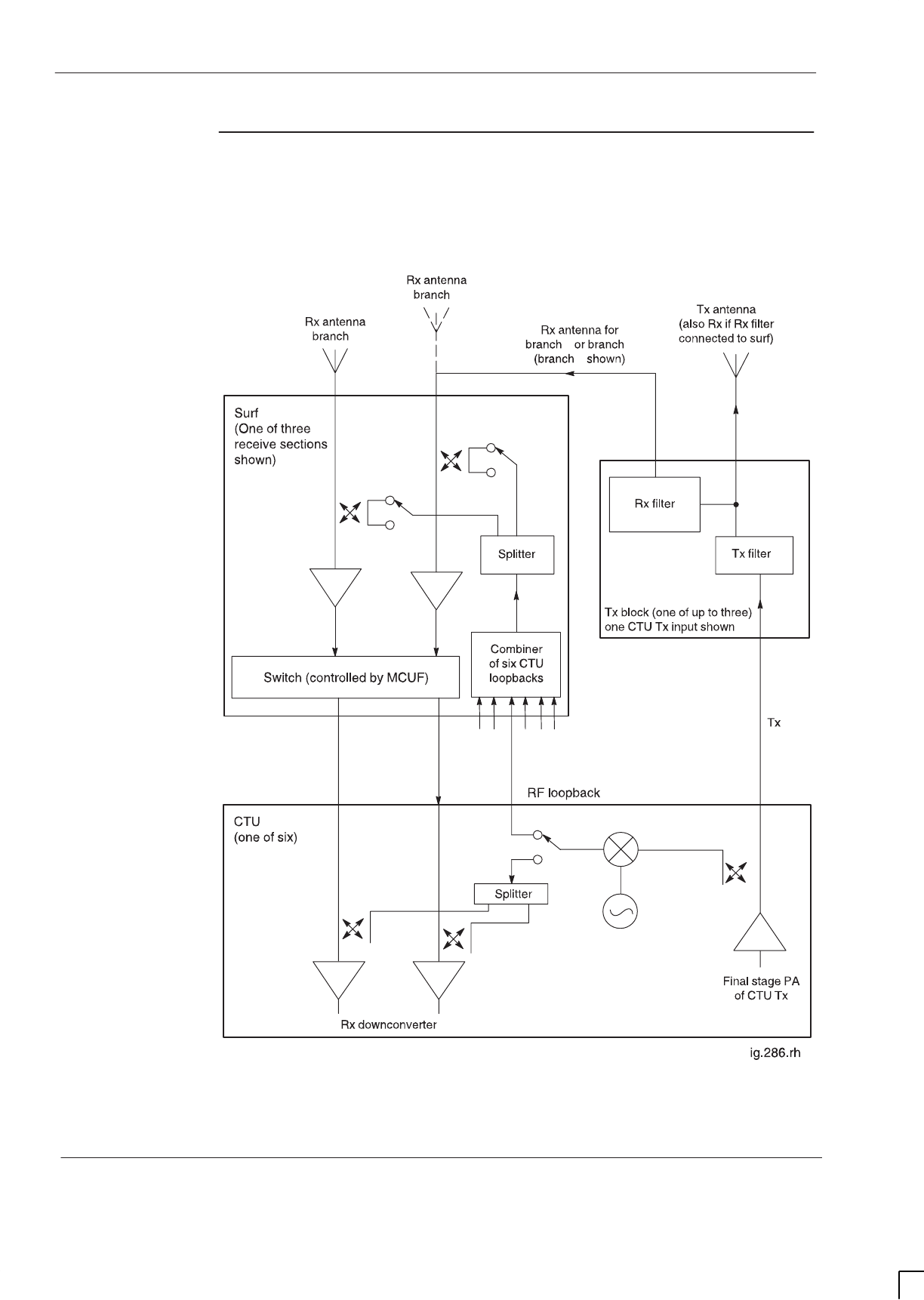
GSM-205-323
RF overview and RF test function
31st Oct 01
Tech. 5–6
Technical Description: Horizon
macro
indoor
CONTROLLED INTRODUCTION
68P02902W07-B
Functional
diagram of RF
Figure 5-1 shows the basic RF and loopback/VSWR test functions. For clarity,
only one CTU and one Tx block is shown, and part of the SURF. CCBs could be
used instead of Tx blocks.
RxA RxB
B
AAB
B
Figure 5-1 RF functional diagram

GSM-205-323 RF overview and RF test function
31st Oct 01
Technical Description: Horizon
macro
indoor
68P02902W07-B
CONTROLLED INTRODUCTION
Tech. 5–7
Description of
RF test modes
The following description should be read in conjunction with Figure 5-1.
NOTE The RF test capability described requires software load
GSR5 or later.
The loopback test hardware picks up an attenuated signal by coupled link from
the normal CTU transmit signal.
The signal is mixed down to the receive band for testing the Rx functionality of
the SURF and CTU. Power to the loopback circuitry is automatically turned off
when the radio is in normal operation.
SURF test mode
The loopback signal is injected into the antenna receive path of the SURF by
coupled link. This tests the complete SURF and CTU Rx system path.
Test of CTU Rx circuitry
The loopback signal is injected directly internally into the Rx input of the CTU.
This tests the receive portion of the CTU.
VSWR test mode
The test signal, at Rx frequency, is injected into the antenna port through
coupled link on the SURF. Reflected power is monitored by the receive system
to calculate VSWR. Detection of a high VSWR may indicate the presence of a
cable or antenna fault.

GSM-205-323
CTU
31st Oct 01
Tech. 5–8
Technical Description: Horizon
macro
indoor
CONTROLLED INTRODUCTION
68P02902W07-B
CTU
Overview of
CTU
This section provides the technical description of the compact transceiver unit
(CTU).
NOTE The CTU may be an 850 MHz, 900 MHz, 1800 MHz or a
1900 MHz transceiver, depending on requirements. The
functionality of the CTU is the same for all variants.
The CTU:
SGenerates the RF frequencies required to perform the transmit and
receive functions.
SContains the digital circuits required for eight timeslots of channel
equalization, encoding and decoding, and transceiver control logic.
The CTU provides the air interface between a BSS and MSs, with the following
features:
SCapability of diversity reception (input from two antennas) which improves
the quality reception in the presence of multipath fading and interference.
SFrequency change on a timeslot basis for frequency hopping and
equipment sharing.
STransmit power control.
CTU Tx RF output specification
For Tx RF output, see
Technical Description: GSM-205-323
Overview and
specifications .
Location and requirements
The CTU shelf is adjacent to the digital module shelf in the base of the cabinet.
The cabinet can contain six CTUs. A minimum of one CTU must be fitted in
each cabinet.
CTU internal
boards
The CTU is a single field replaceable unit (FRU), which contains:
SCTU transceiver (XCVR) board.
SPower amplifier (PA) board.
SPower supply unit.

GSM-205-323 CTU
31st Oct 01
Technical Description: Horizon
macro
indoor
68P02902W07-B
CONTROLLED INTRODUCTION
Tech. 5–9
Alarm reporting
The CTU status is displayed by LED indicators on the front panel, as shown in
Figure 5-2, and detailed in Table 5-1. Major sub-systems, such as synthesizers
and RF amplifiers, are monitored, with alarm signals as necessary.
Table 5-1 CTU front panel status indicators
Indicator LED When the LED is Then CTU
RADIO
STATUS
OFF Module off
STATUS Flashing green Code required or being loaded
Green Normal operational mode
Flashing yellow Test mode
Yellow Radio inhibited
Red Alarm condition
Transmit (Tx)
STATUS
OFF Transmitter is off
STATUS Yellow Transmitter is keyed on
RADIO
STATUS AND
TRANSMIT
(Tx) STATUS
Both LEDs flashing
rapidly Non-volatile memory boot code
upgrade
(Do not remove power or reset –
see CAUTION)
CAUTION When both LEDs are flashing, the boot code is
downloading into non-volatile memory for software
upgrade. Power should not be removed, nor the cabinet
reset, until downloading has been completed, as this will
corrupt the non-volatile memory. If the boot code is
corrupted, contact Motorola Customer Network Resolution
Centre requesting the boot code restoration procedure
and the appropriate boot code file.
GSM-205-323
CTU
31st Oct 01
Tech. 5–10
Technical Description: Horizon
macro
indoor
CONTROLLED INTRODUCTION
68P02902W07-B
View of a CTU
Figure 5-2 shows the CTU with main features identified.
Tx OUT
CONNECTOR
Tx STATUS LED
HANDLE
M4 MODULE ATTACHMENT
SCREW
M4 MODULE
ATTACHMENT SCREW
TTY INTERFACE
CONTROL
PROCESSOR
TEST INTERFACE
RADIO STATUS LED
RECESSED MANUAL
RESET BUTTON (if fitted)
Rx A
Rx B
LOOPBACK
TEST PORT (L)
BACKPLANE POWE
R
AND SIGNAL
CONNECTOR
Figure 5-2 View of CTU showing main external features
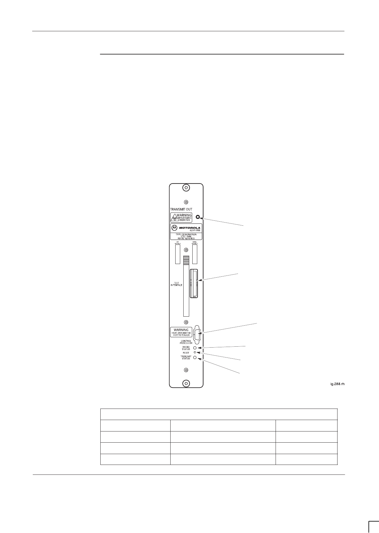
GSM-205-323 CTU
31st Oct 01
Technical Description: Horizon
macro
indoor
68P02902W07-B
CONTROLLED INTRODUCTION
Tech. 5–11
CTU connectors
and reset
The TTY RS-232 serial port has three serial links onto the 9-way connector:
SRadio subsystem (RSS).
SEqualizer and control processor (EQCP).
SChannel coder control processor (CCCP).
A test interface port on the CTU front panel provides access to critical test
points for factory alignment and maintenance.
Pressing the reset push button generates a hard reset of the processor,
initiating a normal power-up. Later versions of the CTU (mid 2001 onward) have
no reset button, reset is acheived by operation of the appproriate CTU circuit
breaker on the CBM.
Figure 5-3 shows the front panel and Table 5-2 lists connector functions.
Tx OUT CONNECTOR
TTY INTERFACE
TEST INTERFACE
Tx STATUS LED
RADIO STATUS LED
.
RECESSED MANUAL
RESET BUTTON (if fitted)
Figure 5-3 CTU front panel
Table 5-2 CTU front panel connectors
Front panel legend Function Connection to
TRANSMIT OUT Transmitter RF output Tx Block
TTY INTERFACE Test access to processor Three RS-232s
TEST INTERFACE Factory use Test equipment
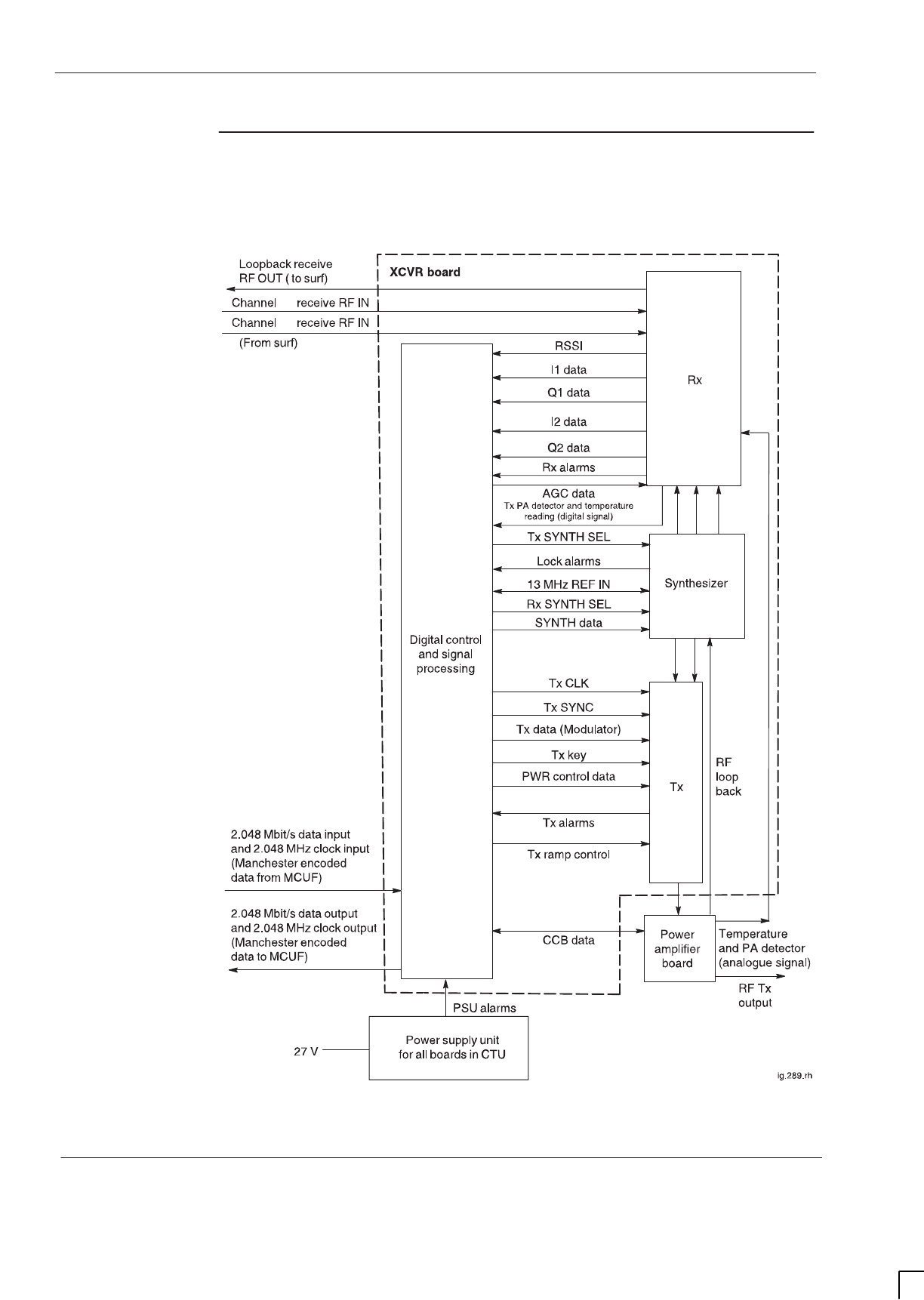
GSM-205-323
CTU
31st Oct 01
Tech. 5–12
Technical Description: Horizon
macro
indoor
CONTROLLED INTRODUCTION
68P02902W07-B
CTU
input/output
diagram
Figure 5-4 shows a block diagram of the CTU with the inputs/outputs annotated.
A
B
Figure 5-4 CTU block diagram
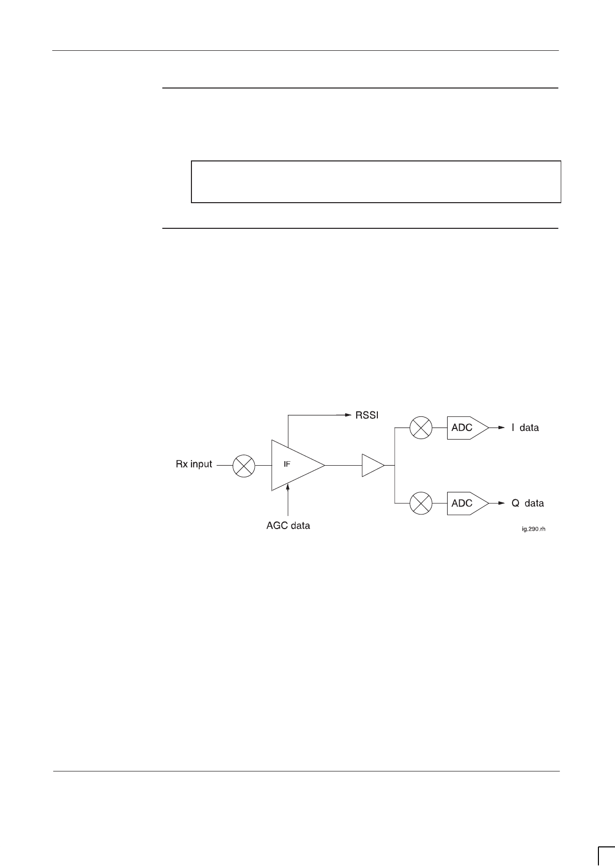
GSM-205-323 CTU
31st Oct 01
Technical Description: Horizon
macro
indoor
68P02902W07-B
CONTROLLED INTRODUCTION
Tech. 5–13
CTU Tx
connector
The CTU Tx connector is a short SMA to SMA link to the base of the
appropriate Tx block or feedthrough plate.
NOTE The Tx cable has a 90° SMA connector at one end and a
straight SMA connector at the other end. The 90° end is
designed for connection to the Tx port of a CTU.
CTU Rx
function
The receiver part of the CTU accepts two amplified and filtered receive antenna
signals from the SURF module. These two signals are applied to inputs (branch
A and branch B) of the CTU transceiver board. Figure 5-5 shows a CTU
receiver functional diagram for one branch.
The input from the SURF module is filtered, amplified and down converted to
ensure the signal level and frequency range are correct for the next stage.
RSSI data (applicable only to GPRS and RACH bursts) is used for automatic
gain control (AGC) to ensure signal strength is correct for the intermediate
frequency (IF) stage.
Figure 5-5 CTU receiver functional diagram for one branch
The primary function of the IF is to filter and amplify the incoming signal.
The path is demodulated into quadrature signals and filtered by baseband
analogue filters. These signals are then digitized (I1/I2 data and Q1/Q2 data)
and made available to the equalizer for the purposes of receive synchronization
and data recovery.
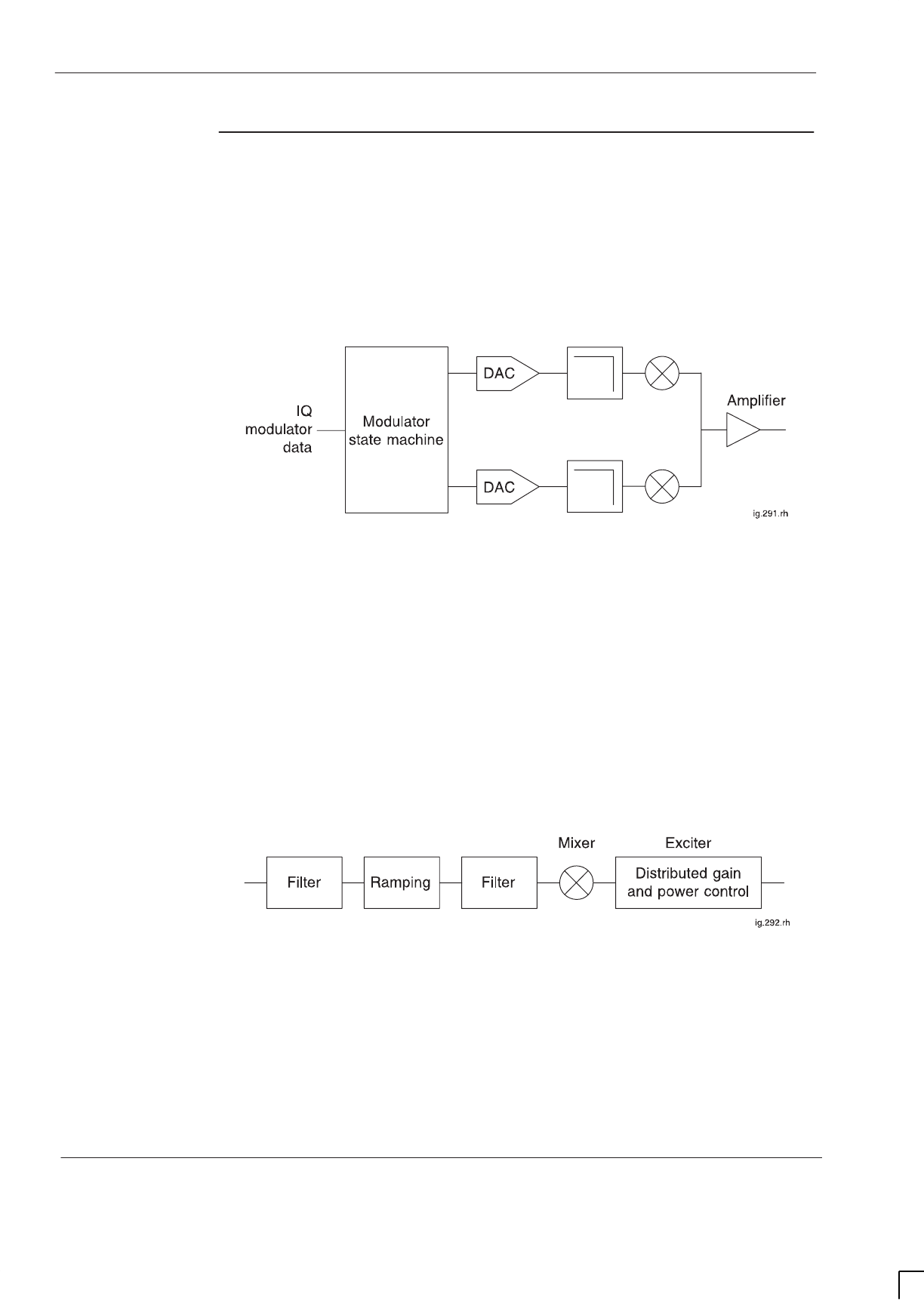
GSM-205-323
CTU
31st Oct 01
Tech. 5–14
Technical Description: Horizon
macro
indoor
CONTROLLED INTRODUCTION
68P02902W07-B
CTU Tx function
IQ modulator
Figure 5-6 shows a functional diagram of the IQ modulator. IQ modulator data
for eight timeslot channels is applied to the modulator state machine. This data
is encoded, serial-to-parallel converted and split into quadrature components.
The quadrature components are D/A converted and applied to a quadrature
modulator to create a Gaussian minimum shift keyed (GMSK) carrier at an
intermediate frequency (IF).
Figure 5-6 IQ modulator functional diagram
IF and exciter stages
Figure 5-7 shows a functional diagram of the IF and exciter stages. The low
level modulated carrier is applied to a combination of analogue and digital
attenuators for RF power control. The power control data comes from the digital
sections of the XCVR. The output of the power control elements is further
amplified by an exciter chain to drive the power amplifier.
The GMSK modulated IF is filtered and applied to the input of a controlled gain
amplifier for transmitter pulse sloping (ramped). The ramped signal is filtered
and then mixed with the main transmitter injection and is upconverted to the
final transmit channel frequency.
Figure 5-7 IF and exciter functional diagram
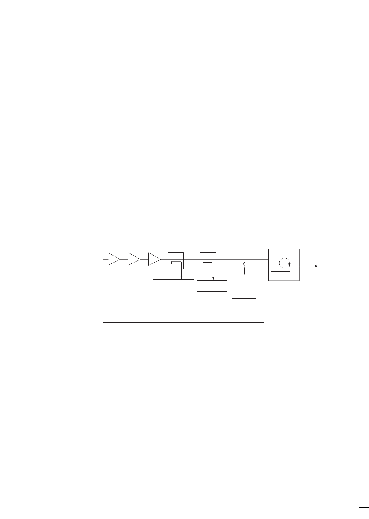
GSM-205-323 CTU
31st Oct 01
Technical Description: Horizon
macro
indoor
68P02902W07-B
CONTROLLED INTRODUCTION
Tech. 5–15
Power amplifier board
Figure 5-8 shows a functional diagram of the power amplifier (PA). The PA
board provides amplification and a forward power detector. The isolator protects
the PA board amplifiers. The detected output is used to adjust the final CTU RF
power output level by the digital sections of the XCVR.
The PA board consists of six functional blocks:
SRF power amplifier.
SRF forward power directional coupler.
SRF forward power detector.
STemperature sensor.
SCCB control.
SRF loopback circuit.
The isolator performs two functions:
SIsolates multiple transmitters to reduce intermodulation distortion.
SProtects the RF power amplifier from possible damage resulting from load
mismatches.
RF FORWARD
POWER
DETECTOR
LOAD
RF OUTPUT
ISOLATOR
RF POWER
AMPLIFIERS
TEMPERATURE
SENSOR CCB
DATA
INJECT
LOOPBACK
DIRECTIONAL
COUPLER
RF LOOPBACK
DIRECTIONAL
COUPLER
PA BOARD
Figure 5-8 Power amplifier board functional diagram
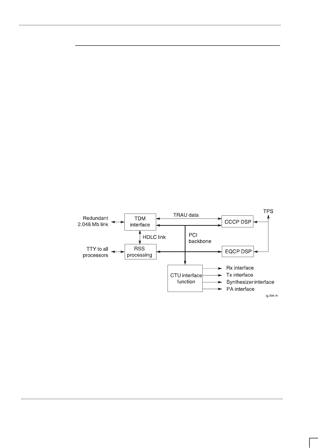
GSM-205-323
CTU
31st Oct 01
Tech. 5–16
Technical Description: Horizon
macro
indoor
CONTROLLED INTRODUCTION
68P02902W07-B
CTU digital
processing and
control
functions
The CTU digital processing and control function provides control and RF
processing for that CTU. These functions include:
S2.048 Mbit/s links which interface with up to two MCUFs for redundancy.
SA software processing platform for the radio sub system (RSS)
SA digital signal processor (DSP) for radio control and channel equalization
(EQCP).
SA DSP for channel coding, data routeing, and baseband hopping (CCCP).
SControl of RF systems: diversity receiver, transmitter, and power amplifier.
SAlarm monitoring of internal devices and external cabinet elements.
SControl of external modules including CCBs, and the SURF.
SMaintenance ports for processor TTY, test point sub system, and CTU test
connections.
Figure 5-9 shows a CTU digital functional diagram.
Figure 5-9 CTU digital functional diagram

GSM-205-323 CTU
31st Oct 01
Technical Description: Horizon
macro
indoor
68P02902W07-B
CONTROLLED INTRODUCTION
Tech. 5–17
2 Mbit/s TDM links
The CTU interfaces to the redundant MCUF are by 2.048 Mbit/s links on the
backplane (or FMUX modules in extension cabinets). These links are
Manchester encoded, thus providing both clock and data in a single connection.
The recovered clock provides a frequency reference for the CTU. The Rx and
Tx circuitry supports FMUX fibre optic lengths of up to 1 km.
The TDM links are formatted into 32 x 64 kbit/s timeslots to provide:
SDownlink and uplink TRAU speech data.
SDownlink baseband hopping data to be routed to/from other CTUs.
SCell site air interface synchronization.
SHDLC channel for control information between RSS and MCUF.
SBaseband routeing information to indicate source of downlink baseband
hopping data.
RSS processor
The RSS processor function communicates with:
SThe MCUF via dedicated 64 kbit/s timeslots in the TDM link.
SThe rest of the digital control functions by the peripheral communications
interface (PCI) bus.
SA dual port interface for communication with the CCCP.
A TTY interface is also provided for user support.
The RSS processor memory includes flash EPROM and 8 Mbytes of DRAM.
Flash EPROM is used for code storage.
EQCP processor
The EQCP processor handles all radio control functions and the channel
equalizer function. The EQCP controls the Rx and Tx function via the CTU
control function on a per timeslot basis. These EQCP functions include:
SAlarm management.
SDownlink burst building and modulator control.
STransmitter power control.
SSynthesizer channel control.
SRF frequency hopping.
SReceiver front end and remote tune combiner control.
SUplink synchronization and equalization.
SDiversity receiver control.
SReceiver automatic gain control (AGC).
SReceive signal strength (RXLEV) calculation.
STiming advance calculation.
SSupport of front panel indicators.
The EQCP communicates with the rest of the digital control functions via the
common PCI bus interface. A TTY interface is provided for radio level
calibration, system monitoring, and CTU level test.

GSM-205-323
CTU
31st Oct 01
Tech. 5–18
Technical Description: Horizon
macro
indoor
CONTROLLED INTRODUCTION
68P02902W07-B
CCCP processor
The CCCP processor handles all the GSM specified layer 1 channel encoding
and decoding functions for speech and control data associated with the air
interface. In addition, it manages the routeing of TRAU frames and baseband
hopping (BBH) data, via the TDM interface, to and from the MCUF. The CCCP
functions include:
SUplink channel decoding.
SDownlink channel encoding.
SGSM specified encryption algorithms.
SBaseband frequency hopping (not supported in GSM850 or PCS1900
BTS variants).
STRAU frame collection and synchronization.
SAlarms management.
The CCCP communicates with the rest of the digital control functions via the
common PCI bus interface. A dual port RAM (DPR) is also used in the downlink
direction for communications from RSS. In addition to the TDM function, a serial
link is provided to support uplink and downlink TRAU data.
CTU interface function
The CTU interface function provides the air interface timing and radio control
circuitry required for Rx (uplink) and Tx (downlink) control functions. A common
PCI bus allows all the processing elements including the RSS processor, EQCP,
and CCCP to communicate with the various CTU functions. The CTU interface
includes:
SMaster GSM air interface timing function.
SIndependent Rx gain control interface for each diversity receiver branch.
SBaseband Rx data interface for each diversity receiver branch.
SReceiver front end and CCB control.
STx data interface including GMSK modulator which provides baseband
data to the transmitter.
STx and power amplifier power control interface.
SRx and Tx frequency synthesizer control which supports RF frequency
hopping.
SCTU and cabinet alarm data collection.
SAlarms sampling and multiplexing.

GSM-205-323 CTU
31st Oct 01
Technical Description: Horizon
macro
indoor
68P02902W07-B
CONTROLLED INTRODUCTION
Tech. 5–19
CTU
uplink/downlink
Downlink traffic data flow
Downlink TRAU data from the MCUF is received by the TDM function then
routed to the CCCP function where it is encoded (cyclic, block, and
convolutional), interleaved, and encrypted to GSM recommendations. Signalling
messages are also received from the RSS processor and encoded. These
traffic and control messages are built into air interface frames and then routed
back to the MCUF via the TDM function for baseband hopping. The CCCP
calculates a BBH routeing word, which informs the MCUF of the radio link to be
the source of its post hopped data. The post hopped data is then once again
sent back down to the appropriate CTU where it is received by the TDM function
and passed to the EQCP function. The EQCP inserts midamble and guard bits
to the data bits and forwards the data on to the modulator for transmission. The
EQCP also programs the CTU for the correct RF channel and transmit power
level for this transmitted burst.
Uplink traffic data flow
Baseband uplink traffic and control data messages are received by the CTU
interface function and sent to the EQCP where they are equalized. The EQCP
also calculates timing advance and RXLEV information, which is forwarded to
the RSS process. The recovered data bits are forwarded into the CCCP
process, where it is de-interleaved, decoded, and decrypted into TRAU frames.
Control messages are passed to the RSS function, while TRAU frames are sent
to the MCUF via the TDM interface.
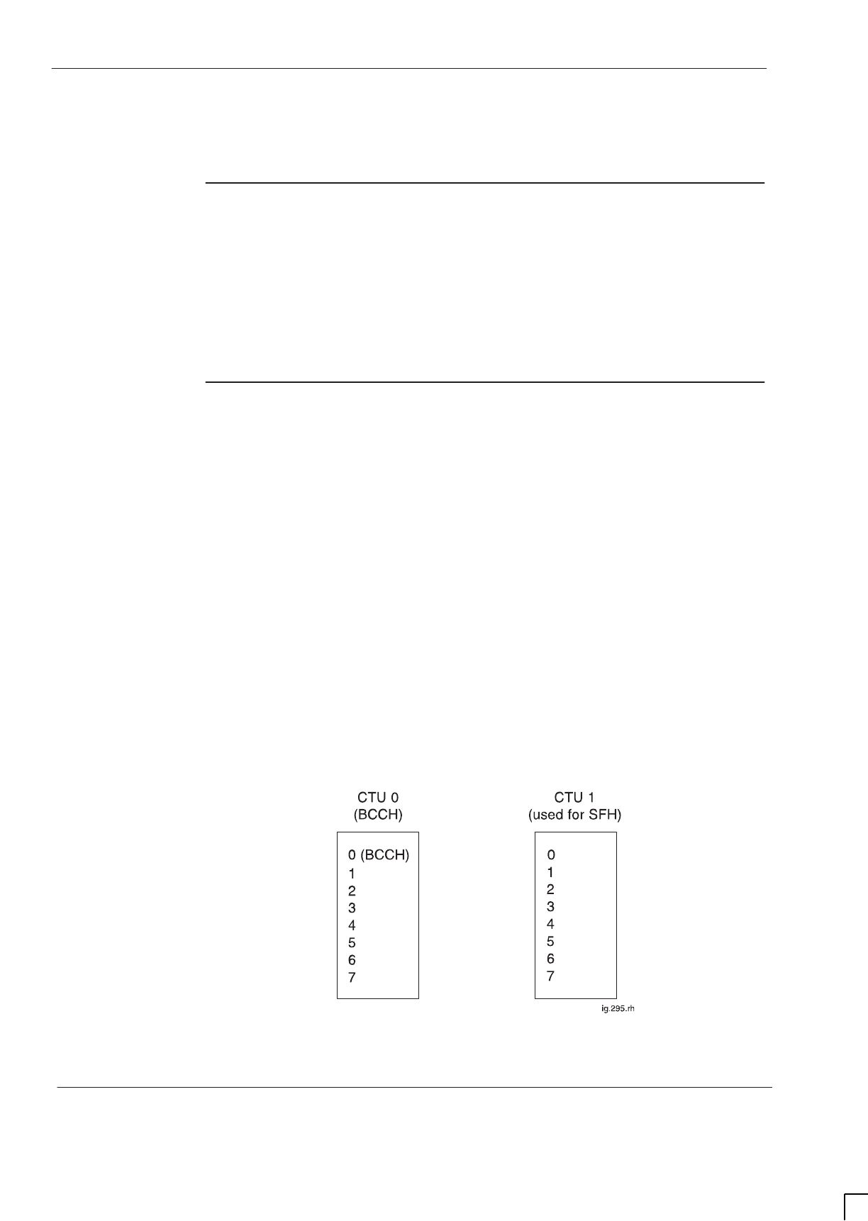
GSM-205-323
CTU frequency hopping
31st Oct 01
Tech. 5–20
Technical Description: Horizon
macro
indoor
CONTROLLED INTRODUCTION
68P02902W07-B
CTU frequency hopping
Overview of
CTU frequency
hopping
The CTU supports two types of frequency hopping, synthesizer frequency
hopping (SFH) and baseband frequency hopping (BBH). This section provides
an explanation of both types. In either type, the MS switches channels after
every transmit/receive (Tx/Rx) burst pair. The difference between SFH and BBH
is in the method by which channel switching is achieved at the BTS.
Synthesizer
frequency
hopping (SFH)
SFH uses the frequency agility of the CTU to change Tx/Rx frequency on any
timeslot (TS), without affecting other timeslots.
SFH can only be used with wideband combining.
With SFH, each TS is allocated a number of frequencies (max 64) over which to
perform the hopping. When determining the hardware requirement for CTUs
using SFH the following rules apply:
SA minimum of two CTUs are required per cell due to BCCH requirements.
Timeslot 0 of CTU 0 is used for the BCCH carrier as shown in Figure 5-10.
CTU 0 cannot use SFH. Only CTU 1 and additional CTUs can use SFH.
SHopping through the BCCH carrier (using the BCCH carrier frequency as
one of the SFH frequencies) is permitted except for timeslot 0. However,
the corresponding timeslot for the BCCH CTU will be switched off for this
period.
Figure 5-10 shows the minimum SFH requirement.
Figure 5-10 Minimum SFH requirement

GSM-205-323 CTU frequency hopping
31st Oct 01
Technical Description: Horizon
macro
indoor
68P02902W07-B
CONTROLLED INTRODUCTION
Tech. 5–21
SFH example
not through
BCCH
CTU 0
In this example of SFH, CTU 0 provides the BCCH and cannot frequency hop.
CTU 0 has to transmit at maximum cell site power to meet the BCCH
requirement. Timeslots are used as shown below:
STS 0 = Combined BCCH TS (BCCH/CCCH/DCCH). Transmitted at
maximum cell site power.
STS 1-7 = Traffic channels, all non-hopping. All traffic channels transmit at
maximum cell site power.
CTU 1 and additional CTUs
CTU 1 and any additional CTUs provide SFH traffic channels as shown below:
STS 0-7 = Frequency hopping traffic channels. The frequency allocated to
the BCCH of CTU 0 cannot be used for frequency hopping purposes.
SFH example
hopping
through BCCH
carrier
CTU 0
In this example of SFH, CTU 0 provides the BCCH and cannot frequency hop.
CTU 0 has to transmit at maximum cell site power to meet the BCCH
requirement. Timeslots are used as shown below:
STS 0 = Combined BCCH timeslot (BCCH/CCCH/DCCH). Transmitted at
maximum cell site power.
STS 1-7 = Unused timeslots transmitting dummy bursts for BCCH. All
channels transmit at maximum cell site power.
CTU 1 and additional CTUs
CTU 1 and any additional CTUs provide SFH traffic channels as shown below:
STS 0 = Frequency hopping traffic channel, but prevented from using
BCCH frequency.
STS 1-7 =Frequency hopping traffic channels, using all available
frequencies, including BCCH.
When the SFH selects the BCCH frequency, the CTU transmits at maximum cell
site power and the corresponding TS on CTU 0 is switched off for this period.
GSM-205-323
CTU frequency hopping
31st Oct 01
Tech. 5–22
Technical Description: Horizon
macro
indoor
CONTROLLED INTRODUCTION
68P02902W07-B
Baseband
frequency
hopping (BBH)
BBH requires all eight timeslots of the CTU Tx (downlink) at the same frequency.
In the Rx (uplink) direction, the frequency agility of the CTU is used to change
timeslot frequencies on a timeslot basis. The BCCH frequency is always
transmitted at maximum cell site power.
BBH can use either Tx blocks or CCB Tx combining equipment. The main
reason for using BBH instead of SFH is to enable frequency hopping when
using CCBs, because the mechanical tuning of CCBs is too slow for SFH.
The number of CTUs required to support BBH is equal to the number of
frequencies used.
NOTE BBH is not supported on GSM850 or PCS1900 BTSs.
BBH example
In Figure 5-11 MSs A, B and C are using TS 5 of CTUs 0, 1 and 2 respectively.
Figure 5-11 Diagram of BBH example using three CTUs
If the MSs are using cyclic hopping across ARFCNs 10, 20, 30 (an example
using EGSM900), each MS must transmit a burst of information each TDMA
frame (4.615 ms) on a different frequency. The data for the burst is received by
each CTU in turn (ARFCN 10, 20, 30), as shown in Table 5-3.
Table 5-3 BBH sequence example (EGSM900)
Burst Sequence
Steps CTU 0
Tx Rx
CTU 1
Tx Rx
CTU 2
Tx Rx
1 A10 A10 B20 B20 C30 C30
2 C10 A20 A20 B30 B30 C10
3 B10 A30 C20 B10 A30 C20
4 (same as 1) A10 A10 B20 B20 C30 C30
5 (same as 2) C10 A20 A20 B30 B30 C10
6 (same as 3) B10 A30 C20 B10 A30 C20
In the uplink direction the controlling CTU (for example CTU 0 for MS A in
Figure 5-11) tunes TS 5 in accordance with the frequency expected from the MS
for that particular burst.
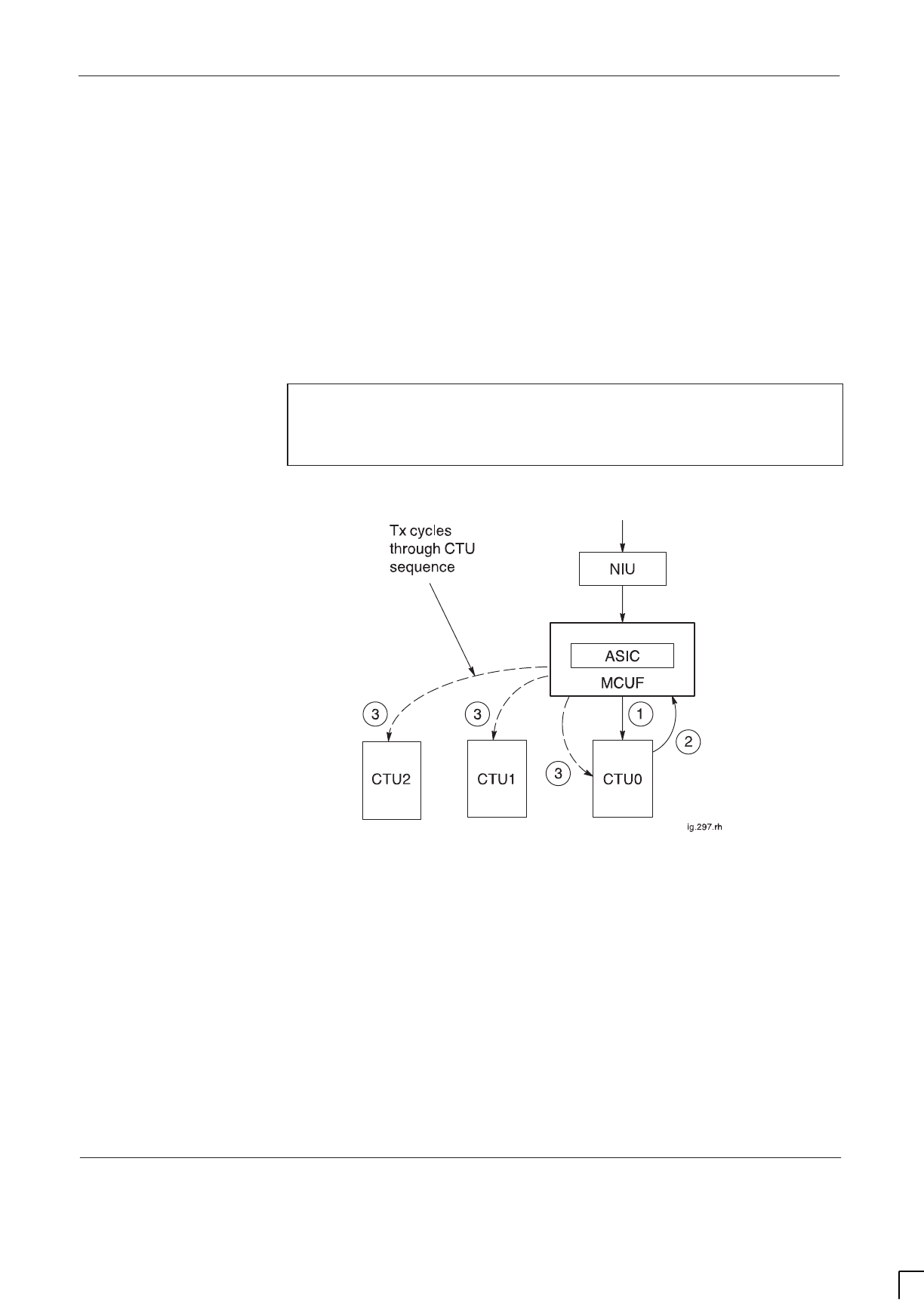
GSM-205-323 CTU frequency hopping
31st Oct 01
Technical Description: Horizon
macro
indoor
68P02902W07-B
CONTROLLED INTRODUCTION
Tech. 5–23
Transmit
The transmit is described by the following, as shown in Figure 5-12:
1. Traffic data from the network is passed through the NIU to the MCUF.
Within the MCUF an ASIC switches the data to CTU0 (the dedicated CTU
for this particular MS call example).
2. The CTU, having processed the data (channel coding, interleaving,
encryption and routeing information) then passes the data back to the
ASIC.
3. The ASIC follows the BBH routeing information to direct the data to the
next Tx CTU in the sequence of Table 5-3.
NOTE BBH differs from normal and SFH CTU Tx procedures, in
that the data is directed to CTUs in a cyclic sequence at
stage 3. Without BBH, stage 3 always routes data to the
original CTU.
Figure 5-12 shows a schematic diagram of an example of base band hopping.
Figure 5-12 Schematic of BBH example
Receive
Data from the MS is received by one CTU allocated to that MS (in this case
CTU0). The CTU will synthesize hop to the Rx signal. This ensures that the
handover and equalizers within only one CTU will be connected to a particular
MS.

GSM-205-323
SURF module
31st Oct 01
Tech. 5–24
Technical Description: Horizon
macro
indoor
CONTROLLED INTRODUCTION
68P02902W07-B
SURF module
SURF module
overview
The sectorized universal receiver front end (SURF) module is located in a slot at
the rear of the cabinet top panel. Three connectors on the underside of the
module connect to the SURF harness which provides connectivity to up to six
compact transceiver units (CTUs). Antenna connections are located on the top
of the unit.
There are six types of SURF module available for the Horizon
macro
indoor BTS,
depending on the frequency variant:
S850 (MHz) single band SURF.
S900 (MHz) single band SURF.
S900 (MHz) dual band SURF.
S1800 (MHz) single band SURF.
S1800 (MHz) dual band SURF.
S1900 (MHz) single band SURF.
The single band SURFs contains three amplifier sections for connection to three
pairs of receive antenna inputs providing reception at the appropriate frequency.
The 900 dual band SURF contains three amplifier sections for connection to
three pairs of antennas providing 900 MHz reception and, being dual band, a
further amplifier section for connection to a pair of 1800 MHz receive antennas.
The 1800 dual band SURF similarly contains three amplifier sections for
connection to three pairs of antennas providing 1800 MHz reception and a
further amplifier section for connection to a pair of 900 MHz receive antennas.
Each amplifier section provides two receive outputs which may be directed to
any of the six CTUs, by the switch section. There are three connections to each
CTU; RxA, RxB and loopback test (L).
The two receive outputs from amplifier 0 are split and may be used as
extensions to other cabinets if required. These act as extended antenna
connections from antenna 0. The extension cables are connected to the
receive antenna connection ports on the SURF of the extension cabinet (which
is able to respond to each amplified signal as if it were a normal antenna input).
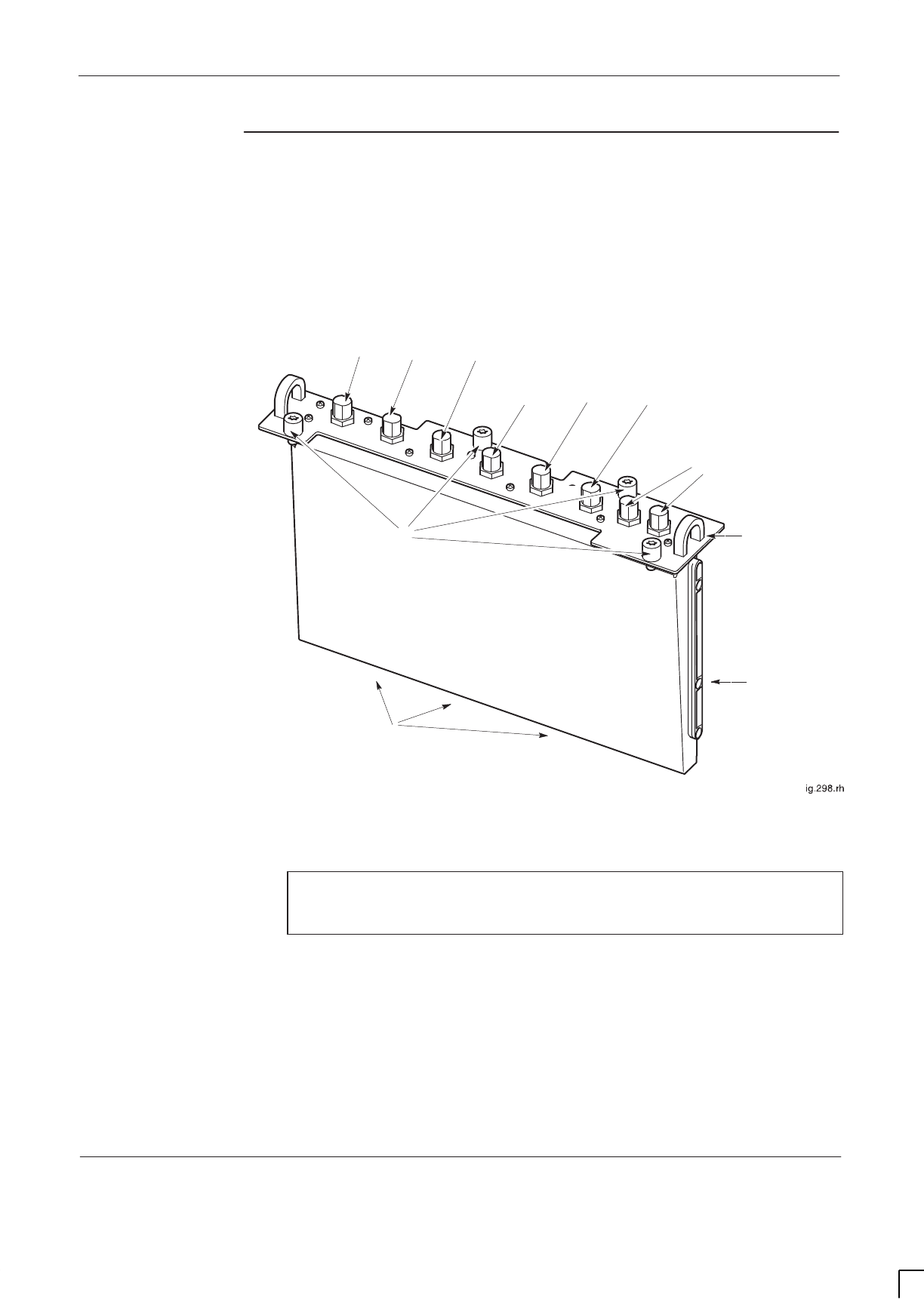
GSM-205-323 SURF module
31st Oct 01
Technical Description: Horizon
macro
indoor
68P02902W07-B
CONTROLLED INTRODUCTION
Tech. 5–25
Single band
SURF module
view
Figure 5-13 shows the view of a single band SURF module with features
identified.
RXn
1B
RXn
2B
GUIDE RAIL FOR
INSERTION
SIX N-TYPE RECEIVE ANTENNA CONNECTIONS
(2 PER DLNB EQUIVALENT)
EXTENSION PORTS TO
OTHER CABINETS
3 CONNECTORS ON UNDERSIDE
TO SURF HARNESS
HANDLE FOR
MODULE
REMOVAL
M6 MODULE
ATTACHMENT
SCREWS
RXn
0A
RXn
1A
RXn
2A
RXn
0B
SURF
MODULE
Figure 5-13 View of single band SURF module with features identified
NOTE Where RXn appears in Figure 5-13, the n may be 850,
900, 1800 or 1900, depending on the frequency of the
SURF module.

GSM-205-323
SURF module
31st Oct 01
Tech. 5–26
Technical Description: Horizon
macro
indoor
CONTROLLED INTRODUCTION
68P02902W07-B
Functional
description of
the single band
SURF
The single band SURF provides front end filtering, amplification, and matrix
control of the RF receive signal between the antenna and the CTU
The single band SURF functional sections (Figure 5-14) consist of loopback,
filtering, amplification, splitting, digital processing and power selection.
Each section is duplicated for the second diversity path except for the digital
and dc power section which is shared by the two diversity paths. There are
three antenna pair inputs (ANT 0, ANT 1 and ANT 2) for each of the two
diversity branches (Branch A and Branch B). There are six outputs to the CTU
for each of the two diversity branches as well as one input from the CTU for the
loopback (LPBK) signal. There is also an output for an expansion cabinet for
ANT 0 on each branch.
The software database must be configured at the OMC-R to accept CTUs of the
same frequency as the single band SURF module in the cabinet.
The digital section switch, under the control of the database (signalled through
the MCUF and CTUs), routes the six amplifier outputs to the appropriate CTUs.
The digital and power supply section is also responsible for loopback switch
control, manual overrides, alarms and dc voltages.
The RF loopback test function is described in RF overview and RF test
function in this chapter.
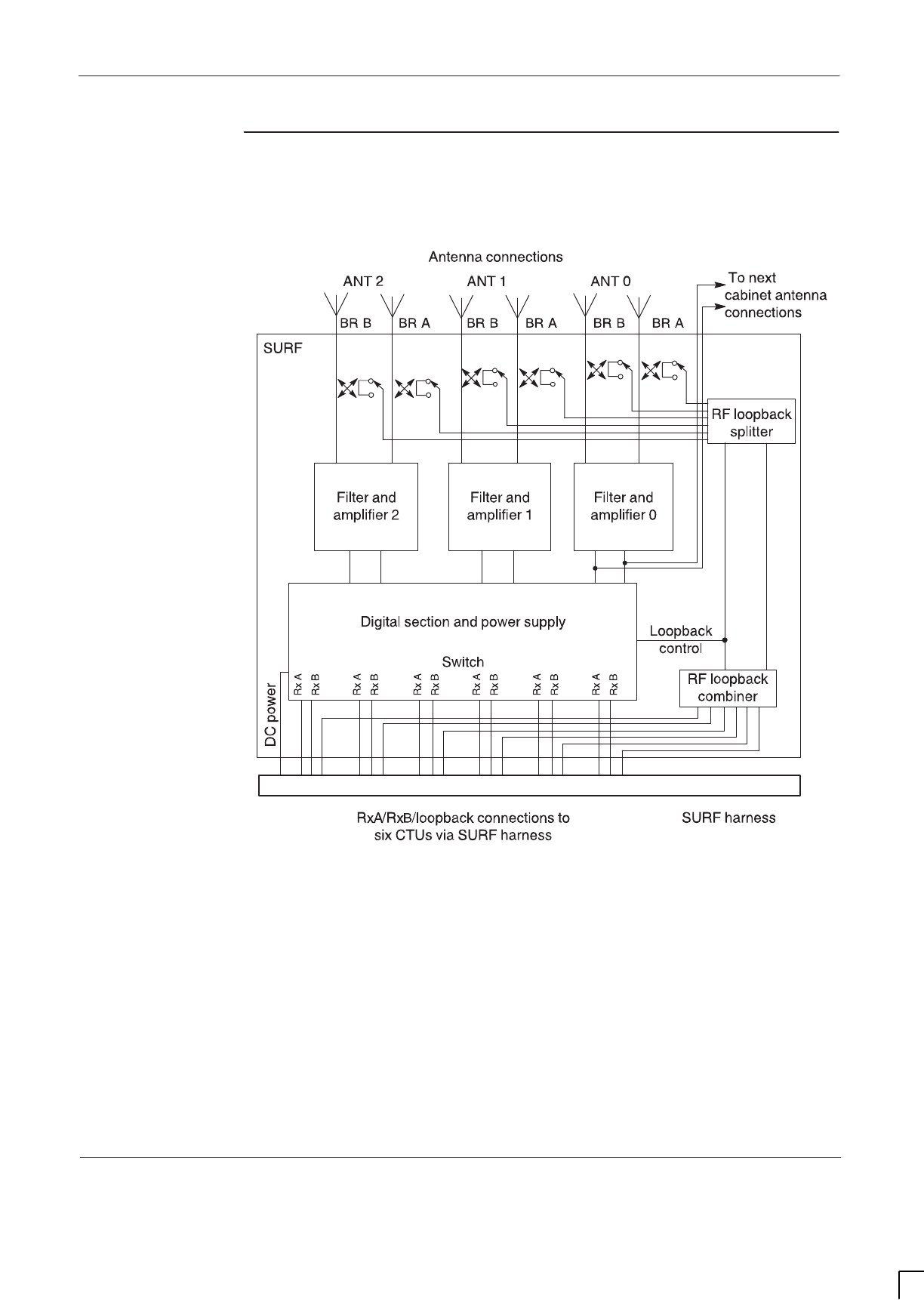
GSM-205-323 SURF module
31st Oct 01
Technical Description: Horizon
macro
indoor
68P02902W07-B
CONTROLLED INTRODUCTION
Tech. 5–27
Single band
SURF functional
diagram
Figure 5-14 shows a functional diagram of the single band SURF module.
Figure 5-14 Functional diagram of the single band SURF module
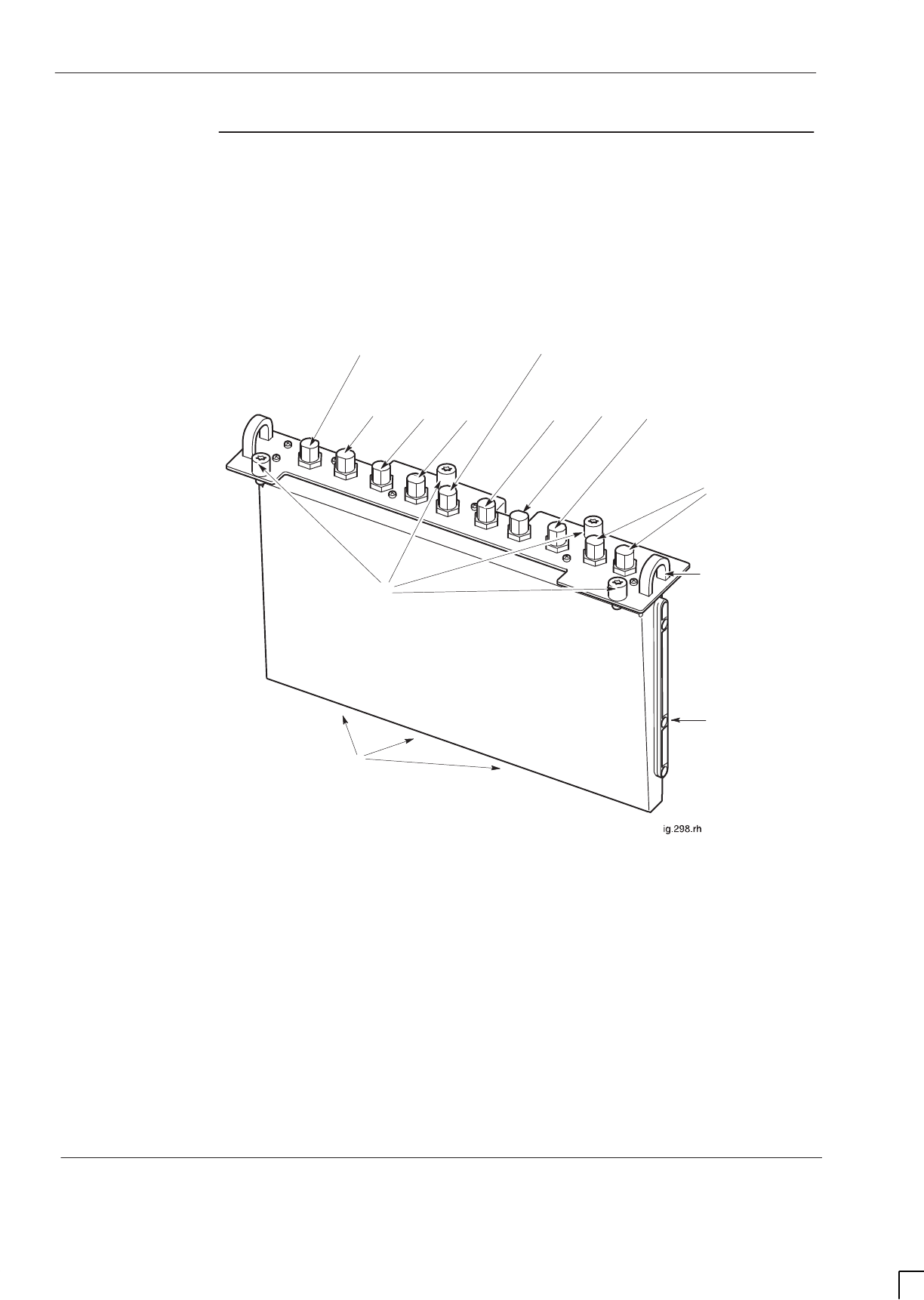
GSM-205-323
SURF module
31st Oct 01
Tech. 5–28
Technical Description: Horizon
macro
indoor
CONTROLLED INTRODUCTION
68P02902W07-B
Dual band
SURF module
view
Figure 5-15 shows a view of a dual band SURF module with features identified,
both the 900 and 1800 variants are similar in appearance.
GUIDE RAIL
FOR INSERTION
EXTENSION PORTS
TO OTHER CABINETS
3 CONNECTORS ON
UNDERSIDE TO SURF
HARNESS
HANDLE FOR
MODULE
REMOVAL
M6 MODULE
ATTACHMENT SCREWS
DUAL BAND
SURF
EIGHT N-TYPE RECEIVE ANTENNA CONNECTIONS
(2 PER DLNB EQUIVALENT)
SECOND
FREQUENCY Rx 0B
MAIN FREQUENCY
Rx 1BRx 2B Rx 0B
SECOND
FREQUENCY Rx 0A
Rx 0ARx 1ARx 2A
MAIN FREQUENCY
Figure 5-15 View of dual band SURF module with features identified

GSM-205-323 SURF module
31st Oct 01
Technical Description: Horizon
macro
indoor
68P02902W07-B
CONTROLLED INTRODUCTION
Tech. 5–29
Functional
description of
dual band SURF
modules
The dual band SURF modules provide front end filtering, amplification, and
matrix control of the RF receive signal between the antenna and the CTU. The
dual band SURFs each have three antenna pair connections providing main
frequency reception, and one antenna pair providing reception on a second
frequency. The two types of dual band (DB) SURF enable 900 CTUs to be
mixed with 1800 CTUs in any combination, up to the maximum total of six CTUs
per cabinet.
The software database must be configured at the OMC-R to accept 1800 CTUs
and 900 CTUs in the appropriate cabinet locations.
The dual band SURF functional sections (Figure 5-16) consist of loopback,
filtering, amplification, splitting, digital processing and power selection.
Each section is duplicated for the second diversity path except for the digital
and dc power section which is shared by the two diversity paths. There are four
antenna pair inputs (ANT 0, ANT 1, ANT 2 and ANT DB) for each of the two
diversity branches (Branch A and Branch B). There are six outputs to the CTU
for each of the two diversity branches as well as one input from the CTU for the
loopback (LPBK) signal. There is also an output for an expansion cabinet for
ANT 0 on each branch.
Digital codes are transmitted from the 900 CTUs and 1800 CTUs to the digital
section. The digital codes are dissimilar in order that 900 or 1800 CTUs can be
recognized and appropriate switching can be made to required antenna for
transmission and reception.
The digital and power supply section is also responsible for loopback switch
control, manual overrides, alarms and dc voltages.
The RF loopback test function is described in RF overview and RF test
function in this chapter.
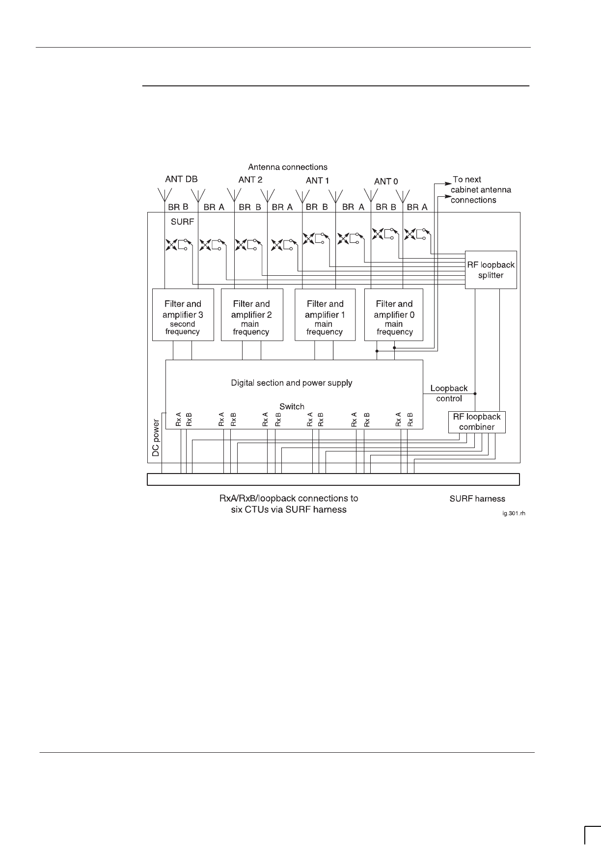
GSM-205-323
SURF module
31st Oct 01
Tech. 5–30
Technical Description: Horizon
macro
indoor
CONTROLLED INTRODUCTION
68P02902W07-B
Dual band
SURF functional
diagram
Figure 5-16 shows a functional diagram of the dual band SURF module.
Figure 5-16 Functional diagram of the dual band SURF module

GSM-205-323 Tx blocks overview
31st Oct 01
Technical Description: Horizon
macro
indoor
68P02902W07-B
CONTROLLED INTRODUCTION
Tech. 5–31
Tx blocks overview
Introduction to
transmit blocks
Transmit (Tx) blocks are located in three positions in the basket above the
CTUs. There are four types of transmit (Tx) blocks, three of which are available
as 850, 900, 1800 or 1900 variants, and one dual band variant (for use with
900 MHz or 1800 MHz BTSs only).
CAUTION Unused Tx block locations must be covered with a
blanking plate for correct air flow and EMC shielding.
STDF (850, 900, 1800 or 1900) = Twin duplexed filter.
SDual band TDF (900/1800) = Dual band twin duplexed filter.
SDCF (850, 900, 1800 or 1900) = Duplexed combining bandpass filter.
SDDF (850, 900, 1800 or 1900) = Dual-stage duplexed combining filter.
These Tx blocks are cooled by airflow underneath. The DDF has fins, whereas
the TDF, dual band TDF and DCF do not.
Three types of plate can be located in the basket, one as blanking plate and two
to interface CTU Tx cables:
SBlanking plate. This ensures proper air flow and EMI shielding for an
unused basket Tx Block location.
SFeedthrough plate. This converts two SMA connectors to two N-type
connectors, used for connecting Tx cables to CCBs or DDFs.
SHybrid combining unit (HCU). This combines two SMA connectors to
one N-type, enabling two additional CTUs to be connected to a DDF.
One type of Tx unit is installed in the stacking bracket, and is connected to three
CTUs:
SCCB = Cavity Combining Block.
Two CCBs are required for the six CTUs of a filled cabinet. The CCB has no
duplexing capability and, if a single Rx/Tx antenna is used, connection must be
via an external high power duplexer.
CCBs are not currently available for use with the 850 MHz or 1900 MHz BTS
variants.
Screw retention
in Tx block
locations
The plates are attached to the base of the top panel basket using six M4
screws.
Tx blocks are attached to the top surface of the top panel using two M6 screws.
To ensure correct EMC shielding and general containment, it is important to
ensure that all Tx block/plate screw locations have a screw in place and
tightened to correct torque.
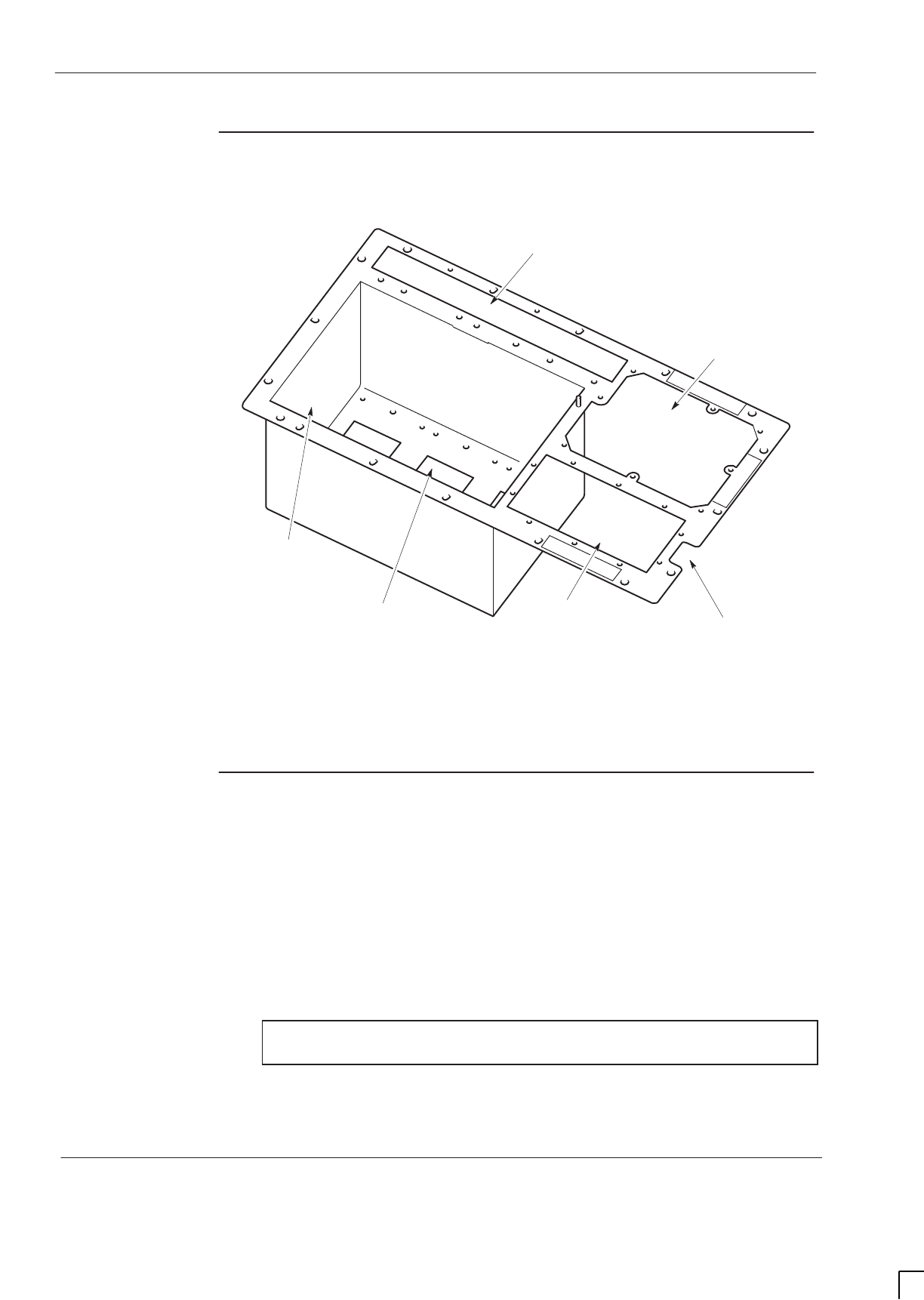
GSM-205-323
Tx blocks overview
31st Oct 01
Tech. 5–32
Technical Description: Horizon
macro
indoor
CONTROLLED INTRODUCTION
68P02902W07-B
View of basket
for Tx blocks
Figure 5-17 shows the top panel and basket which holds the Tx blocks.
ig.235.rh
SLOT FOR SURF MODULE
LOCATION HOLE
FOR INTERFACE
PANEL
VENTILATION PANEL
(LOCATED ABOVE PSMs)
BASKET TO HOLD
THREE Tx BLOCKS
HOLE FOR ONE Tx BLOCK
CTU CONNECTIONS CABLE HOLE FOR FIBRE
OPTIC EXTENSION CABLES
Figure 5-17 View of top panel showing Tx block basket
Transmit block
connectors
The transmit block connectors are of the following types:
SSMA connectors for cables to transceivers.
S7/16 connectors to antennas.
SN-type duplex receive connectors, also used by HCU, CCB inputs and
feedthrough plate.
The SMA connectors are underneath the unit (for ease of connection to the
CTUs), and the other connectors on top, as shown in Figure 5-18.
NOTE All unused SMA inputs to DCF, DDF and HCU modules
must be fitted with 50 ohm load terminations.
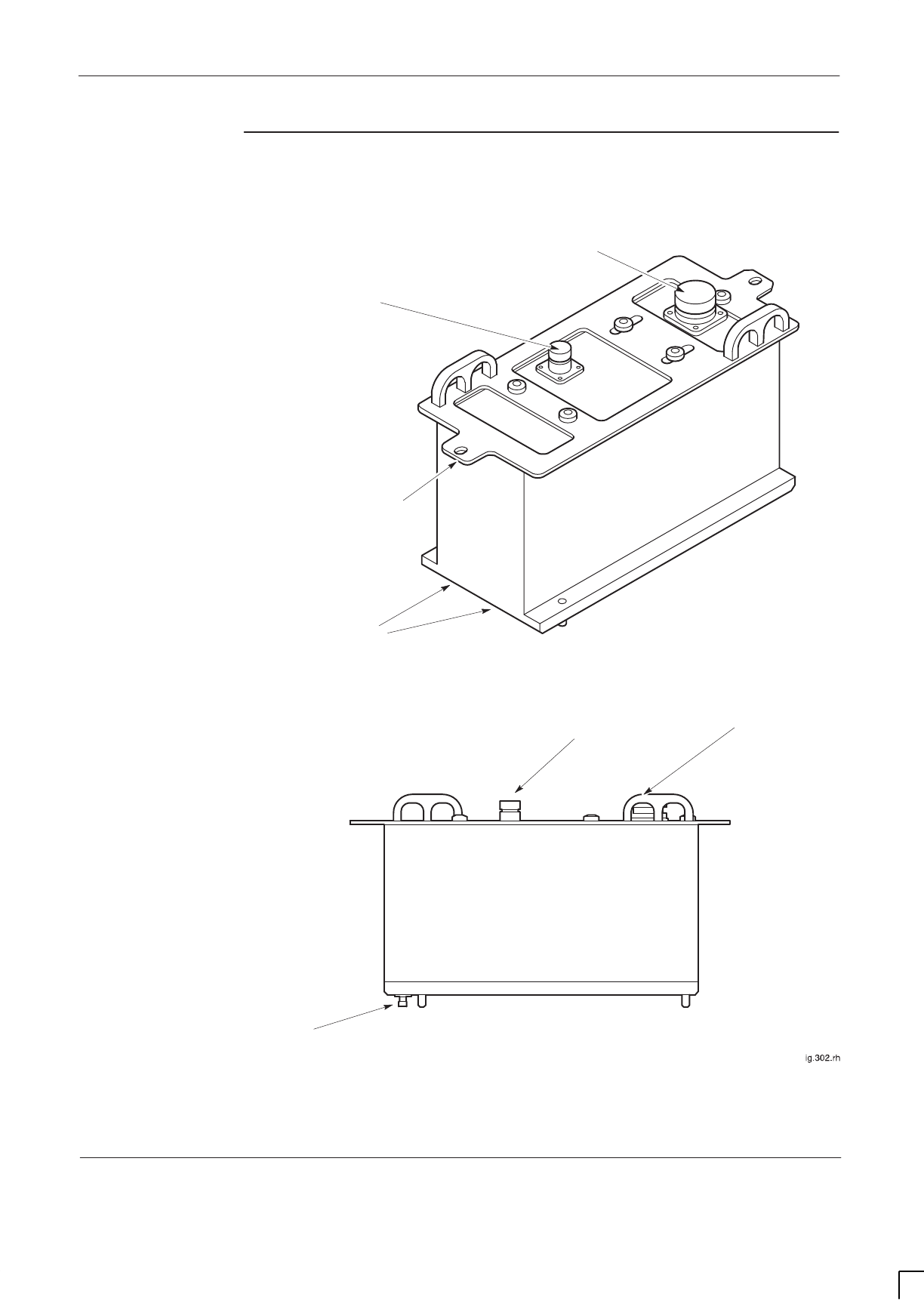
GSM-205-323 Tx blocks overview
31st Oct 01
Technical Description: Horizon
macro
indoor
68P02902W07-B
CONTROLLED INTRODUCTION
Tech. 5–33
View of Tx block
connectors
Figure 5-18 shows a typical Tx block with connector locations.
SMA Tx CONNECTORS
FROM CTUs
SIDE VIEW
ISOMETRIC VIEW
7/16 CONNECTOR TO
ANTENNA
N-TYPE CONNECTOR
TO SURF
HOLE FOR TOP
PANEL BASKET
ATTACHMENT
7/16 CONNECTOR TO
ANTENNA
N-TYPE CONNECTOR
TO SURF
SMA Tx CONNECTORS
FROM CTUs
Figure 5-18 Typical Tx block
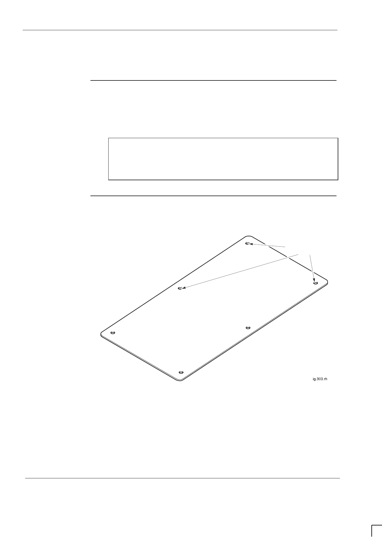
GSM-205-323
Blanking plate
31st Oct 01
Tech. 5–34
Technical Description: Horizon
macro
indoor
CONTROLLED INTRODUCTION
68P02902W07-B
Blanking plate
Purpose of
blanking plate
The blanking plate is fitted in locations where a Tx block is not required. The
blanking plate ensures correct air flow through the cabinet.
The plate is attached to the base of the top panel basket using six M4 screws.
NOTE It is important to ensure that all unused Tx block screw
locations have a screw in place and tightened to correct
torque (see
Technical Description: GSM-205-323
Overview and specifications). This is to ensure
maximum quality of EMC and general containment.
View of
blanking plate
Figure 5-19 shows a view of the blanking plate.
M4 HOLES FOR
ATTACHMENT
Figure 5-19 View of blanking plate

GSM-205-323 Feedthrough plate
31st Oct 01
Technical Description: Horizon
macro
indoor
68P02902W07-B
CONTROLLED INTRODUCTION
Tech. 5–35
Feedthrough plate
Purpose of
feedthrough
plate
The feedthrough plate converts the normal SMA connector from the CTU to an
N-type connector. Each feedthrough plate has a pair of these converters, one
for each of two CTUs. The top N-type connectors are used to connect with
either a CCB, or at the (optional) third Tx port on the top of a DDF Tx block.
The plate is attached to the base of the top panel basket using six M4 screws.
View of
feedthrough
plate
Figure 5-20 shows a top view of a feedthrough plate.
N-TYPE
CONNECTORS FOR
CCBs OR DDFs
SMA CONNECTORS BENEATH
FROM CTUs
M4 HOLES FOR
ATTACHMENT
Figure 5-20 View of feedthrough plate
Feedthrough
plate
connectors
Each feedthrough plate connects to:
SThe Tx outputs of two CTUs, using SMA connectors.
STx inputs of CCBs, or DDFs, using N-type connectors.
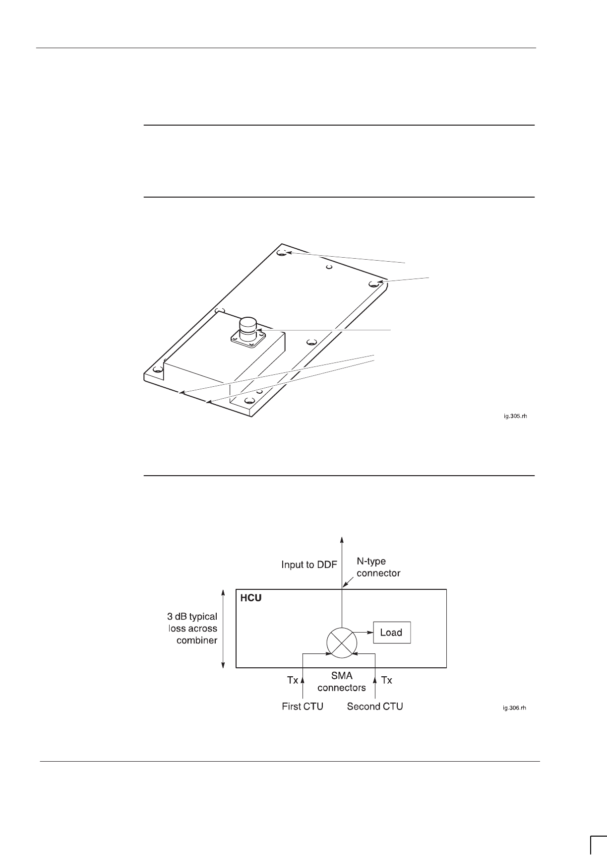
GSM-205-323
HCU plate
31st Oct 01
Tech. 5–36
Technical Description: Horizon
macro
indoor
CONTROLLED INTRODUCTION
68P02902W07-B
HCU plate
HCU overview
The hybrid combining unit (HCU) combines two CTU Tx outputs.
There are six holes for attachment into the bottom of the Tx block basket.
HCU view
Figure 5-21 shows the HCU plate with connectors identified.
N-TYPE CONNECTOR TO DDF
SMA TRANSMIT CONNECTORS
BENEATH HCU MODULE FROM CTUs
M4 HOLES FOR
ATTACHMENT
Figure 5-21 HCU plate view showing connectors
HCU functional
diagram
Figure 5-22 shows a functional diagram of the HCU.
Figure 5-22 HCU functional diagram

GSM-205-323 HCU plate
31st Oct 01
Technical Description: Horizon
macro
indoor
68P02902W07-B
CONTROLLED INTRODUCTION
Tech. 5–37
HCU
connectors
Each HCU connects to:
SThe Tx outputs of two CTUs, using SMA connectors.
SA Tx input of a DDF, using an N-type connector.
NOTE All unused SMA inputs to HCU modules must be fitted
with 50 ohm load terminations.
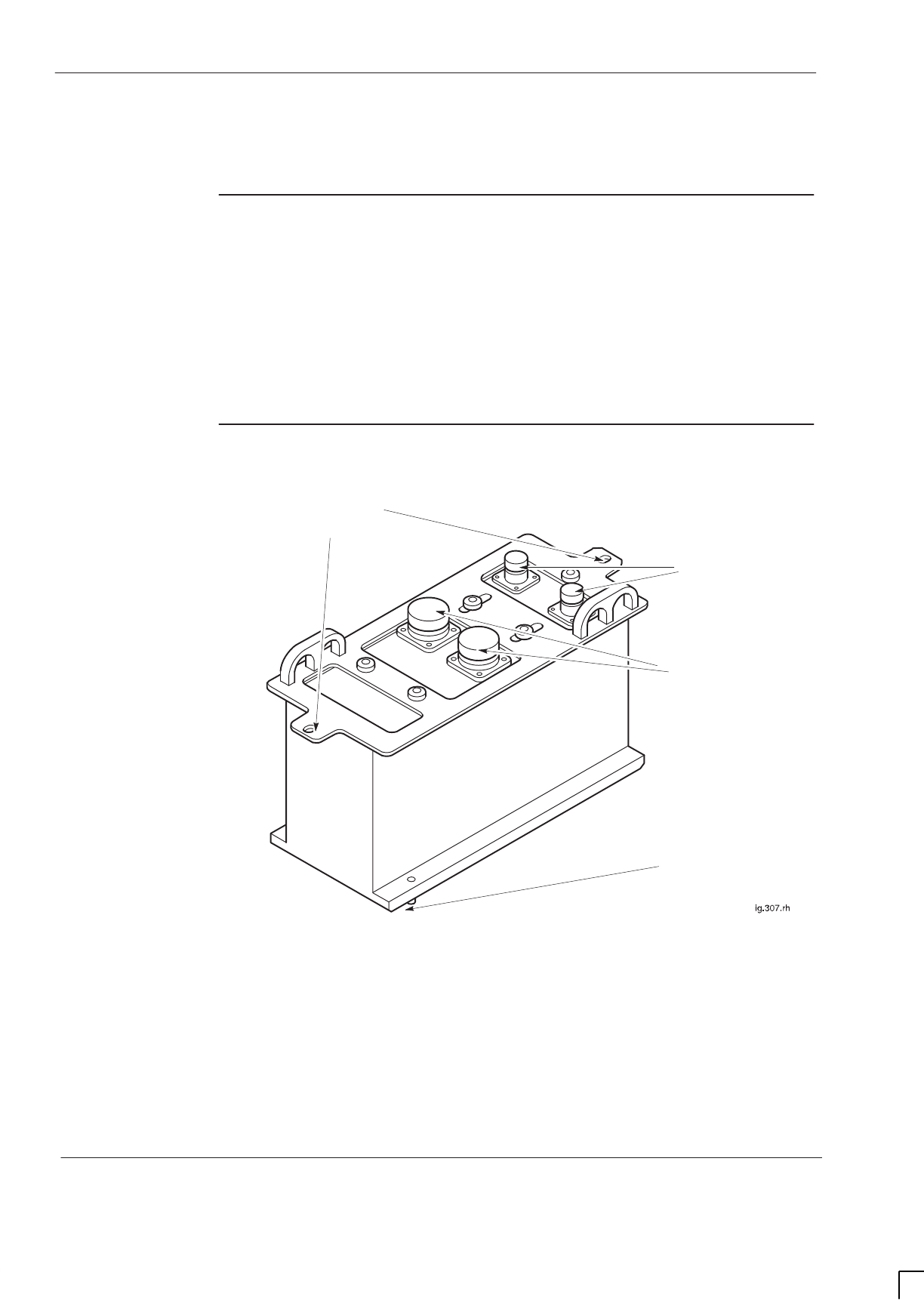
GSM-205-323
TDF
31st Oct 01
Tech. 5–38
Technical Description: Horizon
macro
indoor
CONTROLLED INTRODUCTION
68P02902W07-B
TDF
Overview of
TDF
The purpose of the twin duplexed filter (TDF) Tx block is to enable each
antenna to serve one CTU for both Tx and Rx.
The TDF has two identical sections, each providing a single path from a CTU to
a separate antenna. There is no combining in the TDF.
The TDF is located in the basket above the CTUs, and attached to the top
surface of the top panel using two M6 screws.
TDF view
Figure 5-23 shows the TDF Tx block with connectors identified.
HOLES FOR TOP PANEL
BASKET ATTACHMENT
7/16 CONNECTORS
TO ANTENNAS
TWO SMA Tx
CONNECTORS BENEATH
TDF (FROM CTU)
N-TYPE
CONNECTORS
TO SURF
Figure 5-23 View of TDF Tx block with connectors identified
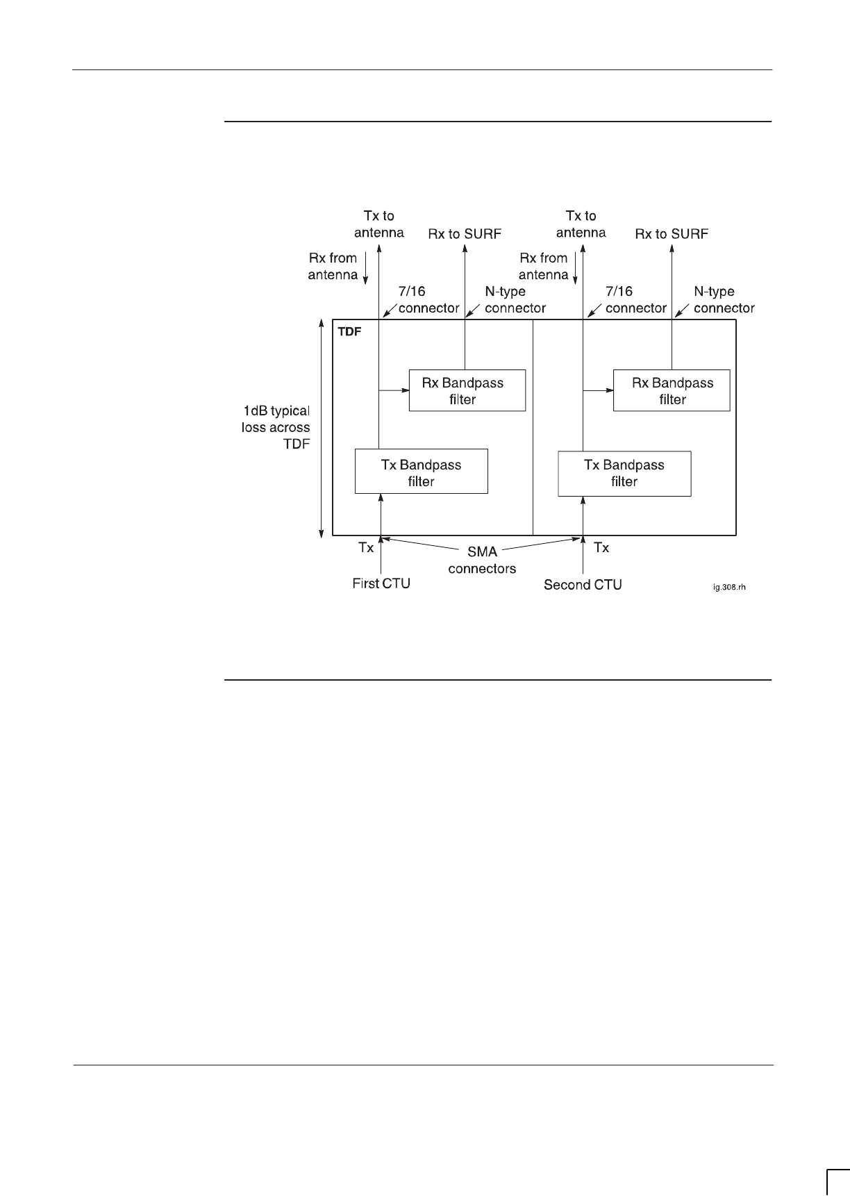
GSM-205-323 TDF
31st Oct 01
Technical Description: Horizon
macro
indoor
68P02902W07-B
CONTROLLED INTRODUCTION
Tech. 5–39
TDF functional
diagram
Figure 5-24 shows a functional diagram of the TDF.
Figure 5-24 TDF functional diagram
TDF connectors
Each TDF connects to:
SThe Tx outputs of two CTUs, using SMA connectors. The two connectors
are underneath the TDF.
STwo antennas, each for both Rx and Tx, using 7/16 connectors. These
connectors are on top of the TDF.
SThe SURF, using two N-type connectors. These connectors are on top of
the TDF.
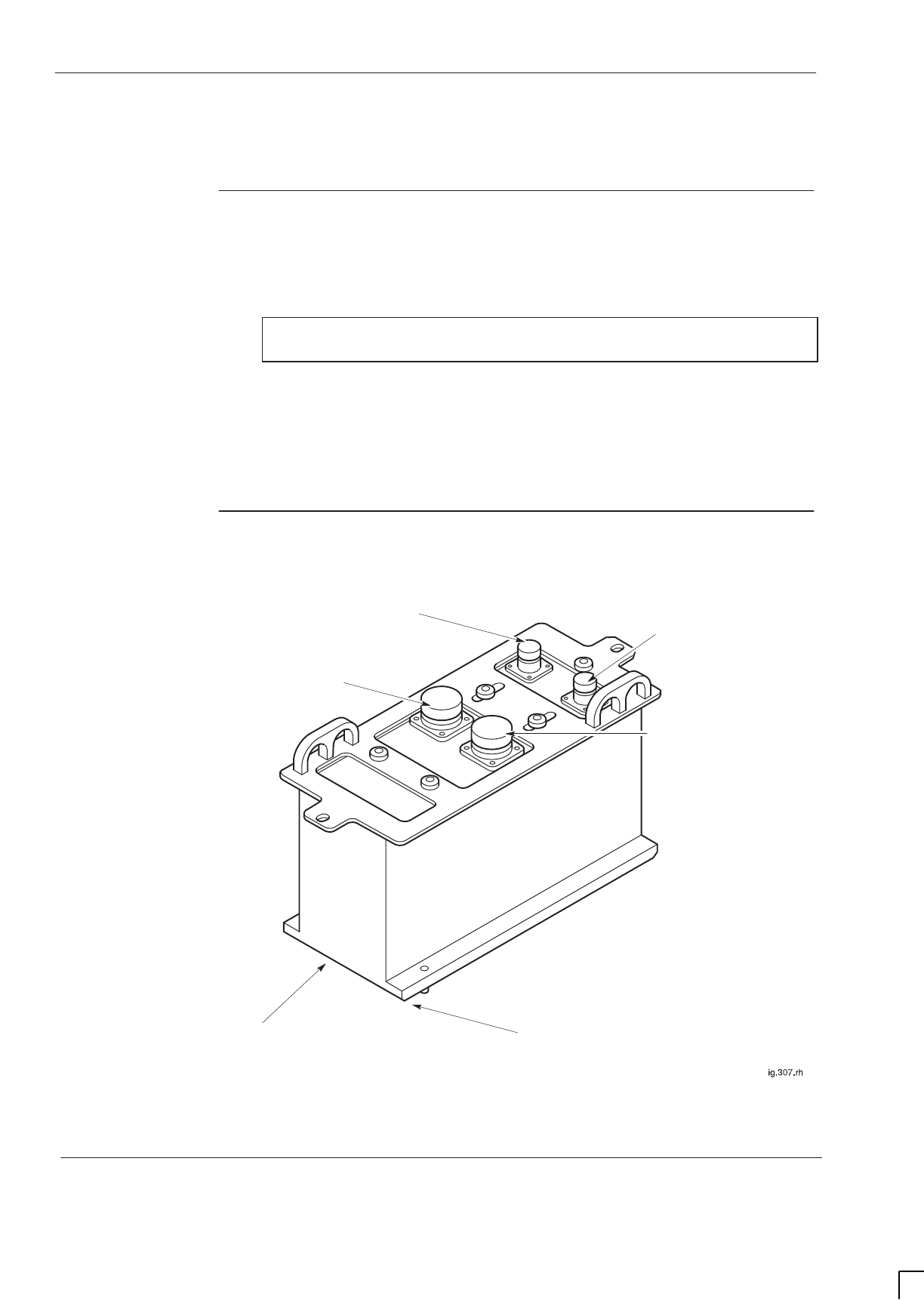
GSM-205-323
Dual band TDF
31st Oct 01
Tech. 5–40
Technical Description: Horizon
macro
indoor
CONTROLLED INTRODUCTION
68P02902W07-B
Dual band TDF
Overview of
Dual band TDF
The purpose of the dual band twin duplexed filter (dual band TDF) Tx block is to
enable one 900 MHz antenna to serve one EGSM900 CTU for both Tx and Rx,
and an 1800 MHz antenna to serve one DCS1800 CTU for both Tx and Rx.
NOTE The dual band TDF for the GSM850 and PCS1900 BTS
variants is not currently available.
The dual band TDF is essentially a TDF with one section providing a path for
900 MHz signals and another section providing a path for 1800 MHz signals.
There is no combining in the dual band TDF.
The dual band TDF is located in the basket above the CTUs, and attached to
the top surface of the top panel using two M6 screws.
Dual band TDF
view
Figure 5-25 shows the dual band TDF Tx block with connectors identified.
7/16 CONNECTOR TO
1800 MHz ANTENNA
(ANT. DCS1800)
SMA Tx CONNECTOR
BENEATH DUAL BAND TDF
(FROM 1800 CTU)
N-TYPE CONNECTOR TO
1800 MHz SURF CONNECTION
N-TYPE CONNECTOR TO
900 MHz SURF CONNECTION
7/16 CONNECTOR TO
900 MHz ANTENNA
(ANT. EGSM900)
SMA Tx CONNECTOR
BENEATH DUAL BAND TDF
(FROM 900 CTU)
Figure 5-25 View of dual band TDF Tx block with connectors identified
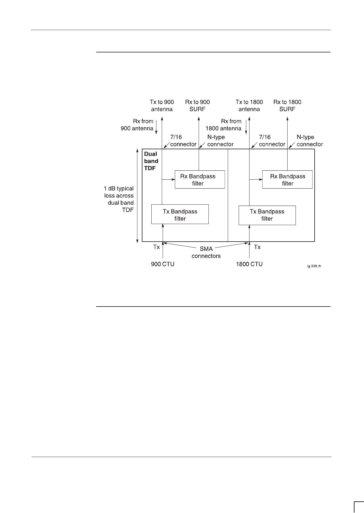
GSM-205-323 Dual band TDF
31st Oct 01
Technical Description: Horizon
macro
indoor
68P02902W07-B
CONTROLLED INTRODUCTION
Tech. 5–41
Dual band TDF
functional
diagram
Figure 5-26 shows a functional diagram of the dual band TDF.
Figure 5-26 Dual band TDF functional diagram
Dual band TDF
connectors
Each dual band TDF connects to:
SThe Tx output of one 900 CTU and one 1800 CTU, using SMA
connectors. The two connectors are underneath the dual band TDF.
SOne 900 MHz antenna and one 1800 MHz antenna. Each antenna is used
for both Rx and Tx, and each is connected to the dual band TDF using
7/16 connectors. These connectors are on top of the dual band TDF.
SA SURF module with dual band capability. Two N-type connectors, located
on top of the dual band TDF, connect one receive path to the SURF’s
900 MHz input and one receive path to the SURF’s 1800 MHz input.
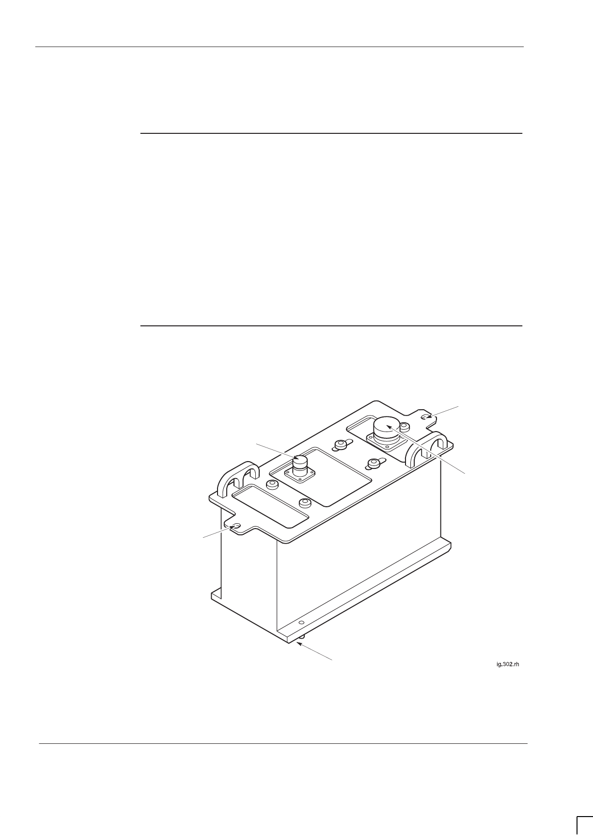
GSM-205-323
DCF
31st Oct 01
Tech. 5–42
Technical Description: Horizon
macro
indoor
CONTROLLED INTRODUCTION
68P02902W07-B
DCF
DCF overview
The purpose of the duplexed combining bandpass filter (DCF) Tx block is to
enable each antenna to serve two CTUs for both Tx and Rx.
The DCF combines two Tx inputs, dissipating half the power within an internal
load.
The signal then passes through a bandpass filter and out to the antenna.
A receive bandpass filter passes only the Rx signal to the SURF module.
The DCF is located in the basket above the CTUs, and attached to the top
surface of the top panel using two M6 screws.
DCF view
Figure 5-27 shows a DCF with connectors identified.
HOLE FOR TOP
PANEL BASKET
ATTACHMENT
N-TYPE CONNECTOR TO
SURF
7/16 CONNECTOR
TO ANTENNA
TWO SMA Tx CONNECTORS
BENEATH DCF (FROM CTU)
HOLE FOR TOP
PANEL BASKET
ATTACHMENT
Figure 5-27 DCF Tx block view with connectors identified
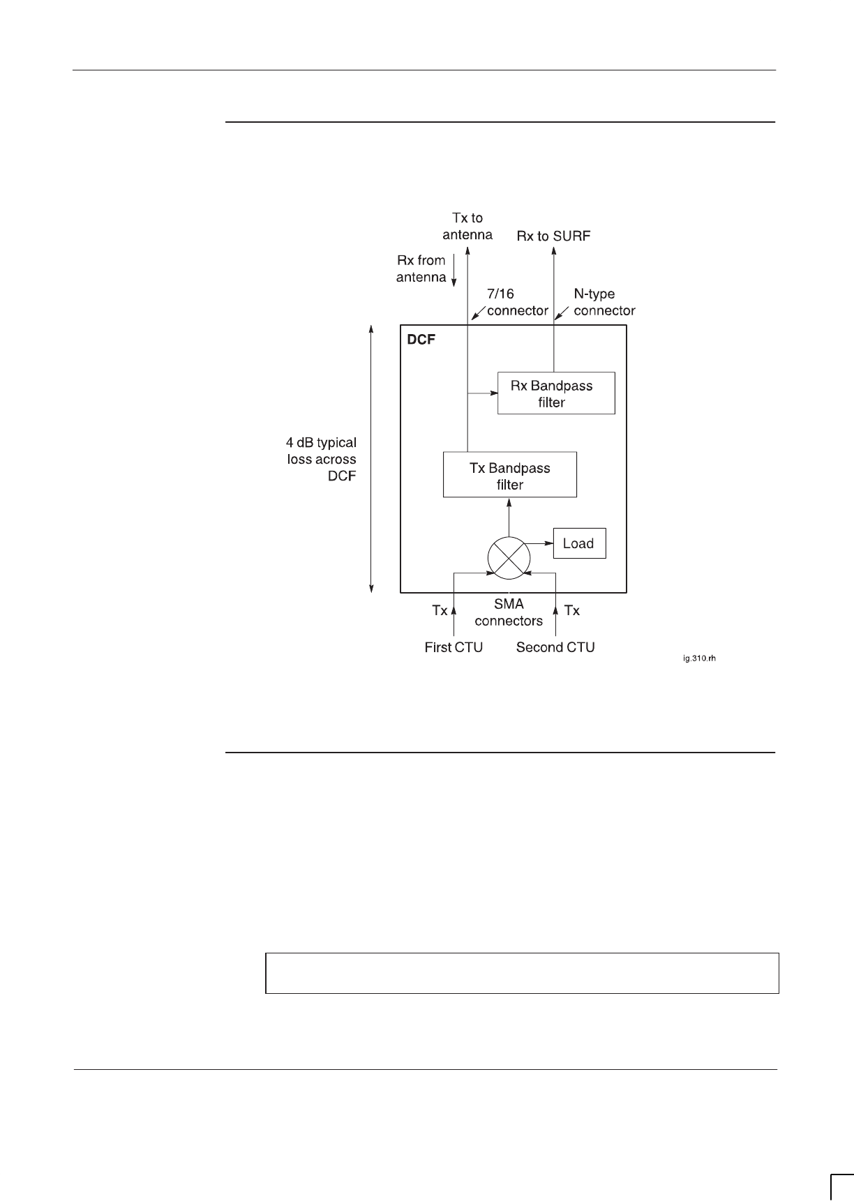
GSM-205-323 DCF
31st Oct 01
Technical Description: Horizon
macro
indoor
68P02902W07-B
CONTROLLED INTRODUCTION
Tech. 5–43
DCF functional
diagram
Figure 5-28 shows a functional diagram of the DCF.
Figure 5-28 Functional diagram of the DCF
DCF connectors
Each DCF connects to:
SThe Tx outputs of two CTUs, using SMA connectors. The two connectors
are underneath the DCF.
SA single antenna for both Rx and Tx, using a 7/16 connector. This
connector is on top of the DCF.
SThe SURF, using an N-type connector. This connector is on top of the
DCF.
NOTE All unused SMA inputs to DCF modules must be fitted with
50 ohm load terminations.
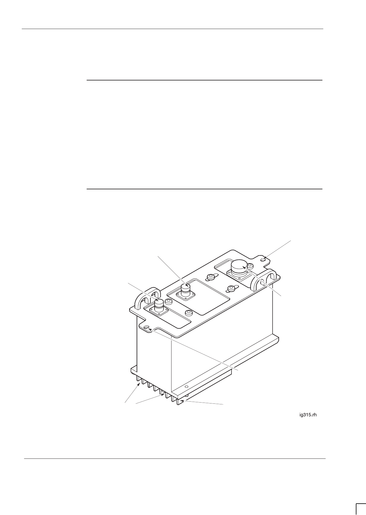
GSM-205-323
DDF
31st Oct 01
Tech. 5–44
Technical Description: Horizon
macro
indoor
CONTROLLED INTRODUCTION
68P02902W07-B
DDF
Overview of
DDF
The dual-stage duplexed combining filter (DDF) differs from the DCF in having a
second stage of combining to allow a third CTU Tx input. This third CTU Tx
input is connected to either:
SA feedthrough plate connector for a single additional CTU or
SAn HCU plate connector for combining two additional CTUs.
The DDF is located in the basket above the CTUs, and attached to the top
surface of the top panel using two M6 screws.
DDF view
Figure 5-29 shows a view of the DDF Tx block with connectors identified.
HOLE FOR TOP
PANEL BASKET
ATTACHMENT
N-TYPE CONNECTOR TO
SURF
TWO SMA Tx CONNECTORS
BENEATH DDF (FROM CTU)
7/16 CONNECTOR
TO ANTENNA
N-TYPE CONNECTOR
FROM CTU BY
FEEDTHROUGH PLATE
OR HCU
HOLE FOR TOP
PANEL BASKET
ATTACHMENT
COOLING FINS
Figure 5-29 DDF Tx block view with connectors identified
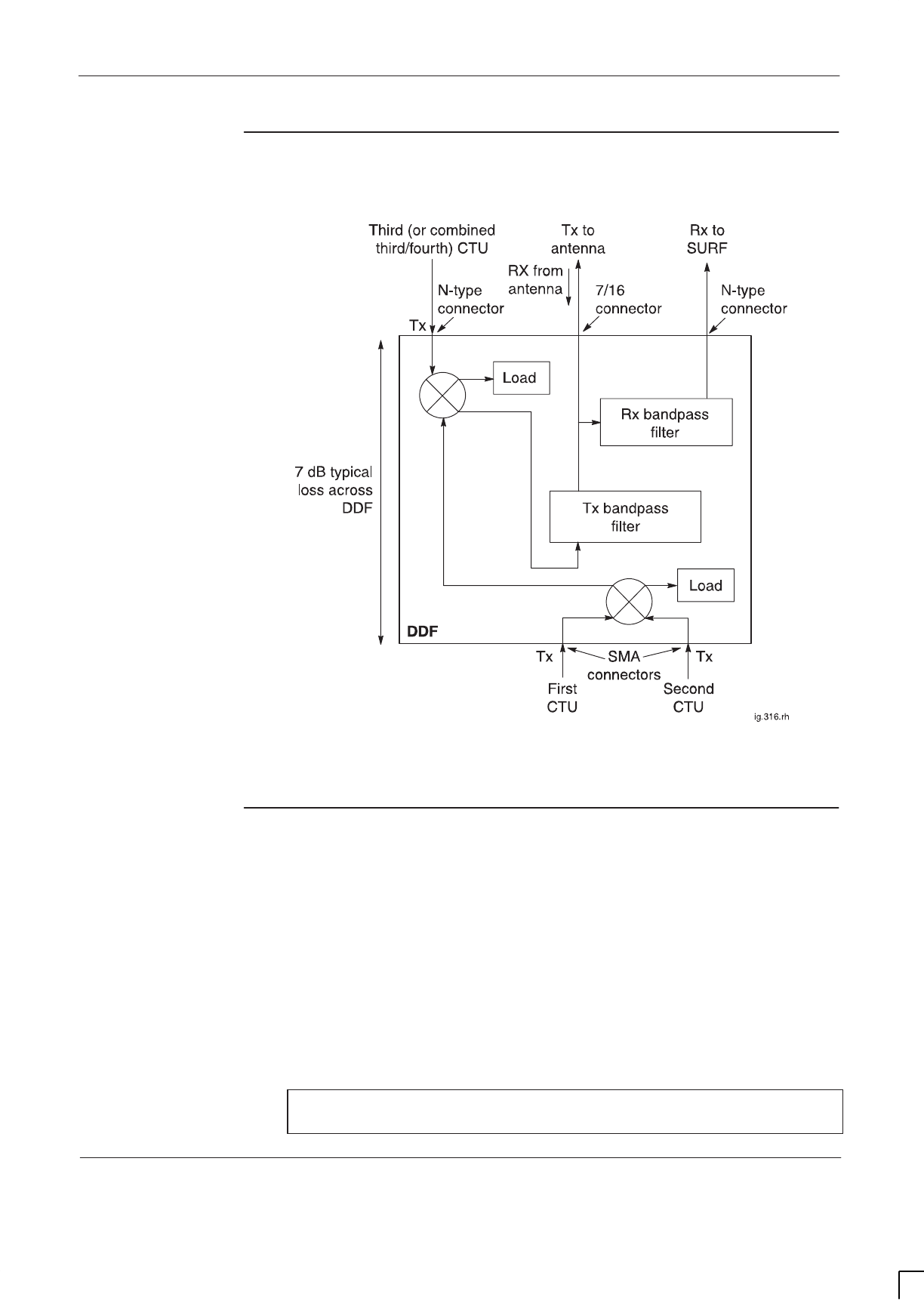
GSM-205-323 DDF
31st Oct 01
Technical Description: Horizon
macro
indoor
68P02902W07-B
CONTROLLED INTRODUCTION
Tech. 5–45
DDF functional
diagram
Figure 5-30 shows a functional diagram of the DDF.
Figure 5-30 Functional diagram of the DDF
DDF connectors
Each DDF connects to:
SThe Tx outputs of three or four CTUs, using:
– Two SMA connectors underneath the DDF.
– An N-type connector on top of the DDF for connection to a
feedthrough plate (for a third CTU) or HCU plate (for combined
third/fourth CTUs).
SA single antenna for both Rx and Tx, using a 7/16 connector. This
connector is on top of the DDF.
SThe SURF, using an N-type connector. This connector is on top of the
DDF.
NOTE All unused SMA inputs to DDF modules must be fitted with
50 ohm load terminations.

GSM-205-323
CCB
31st Oct 01
Tech. 5–46
Technical Description: Horizon
macro
indoor
CONTROLLED INTRODUCTION
68P02902W07-B
CCB
CCB overview
The Cavity Combining Block (CCB) has EGSM900 and DCS1800 variants. A
CCB consists of three independently tuneable cavity resonators, one per CTU.
NOTE CCBs are not currently available for the GSM850 or
PCS1900 BTS variants.
The CCBs are fitted in the CCB basket in the stacking bracket. The basket can
contain up to two CCBs, one for three CTUs. The two CCBs cannot be in
different cabinets because of the short phasing lead connecting the two.
Configurations where five or more carriers per sector are required could utilize
CCBs.
The recommended minimum channel spacing between cavities is 800 kHz.
There are two types of CCB:
SMaster CCB with Band Pass Filter (BPF) and control board.
SExtension CCB, identical to the master CCB but without the BPF and only
having a control board if redundancy is required.
Unlike the Tx blocks, the CCB has no duplexing capability. If a single Rx/Tx
antenna is used then connection to the CCB must be via an external high power
duplexer.
CCB control
board (TCB)
and set switch
The CCB control board is also known as the Transmit Antenna Transceiver
Interface (TATI) control board (TCB).
The CCB control board controls the interface to the CTU. This allows different
vendor CCBs to be installed without requiring amended CTU software.
The address of the control board is set manually using an 8 bit DIL switch, set
by Motorola. Data links are automatically set up.
TCB and link
redundancy
The redundant TCB has the ability to maintain the separated CCB, if the
inter-CCB link fails.
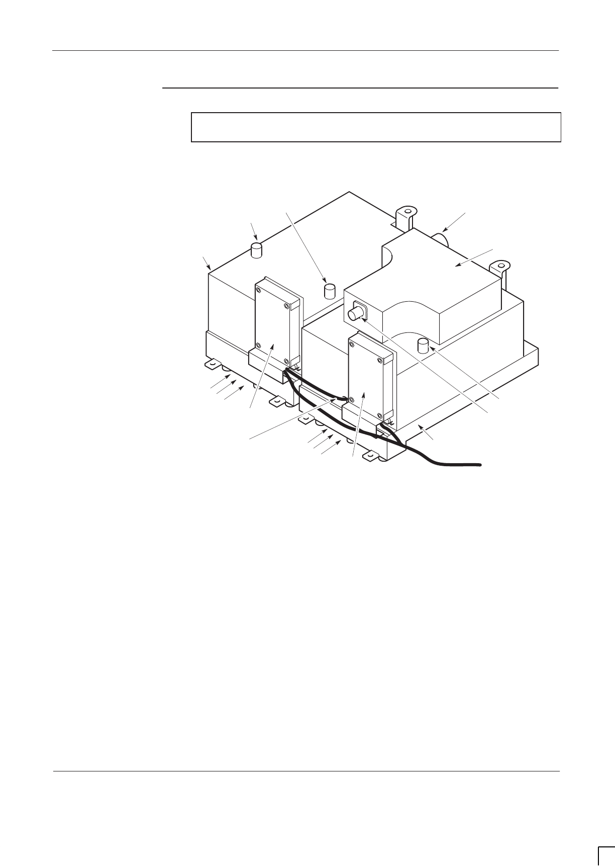
GSM-205-323 CCB
31st Oct 01
Technical Description: Horizon
macro
indoor
68P02902W07-B
CONTROLLED INTRODUCTION
Tech. 5–47
CCB view
NOTE CCBs may vary slightly, depending on manufacturer and
type.
Figure 5-31 shows two EGSM900 CCBs with main and redundant control
boards fitted.
ig.317.rh
BAND PASS FILTER
(BPF)
MASTER CCB
WITH BPF
CCB CONTROL BOARD
(MASTER)
EXTENSION CCB
WITHOUT BPF
CCB CONTROL BOARD
(REDUNDANT)
ANTENNA
CONNECTOR ON BPF
BPF INPUT
FROM CCB
CCB OUTPUT
TO BPF
EXTENSION CCB OUTPUT TO
MASTER CCB
3 Tx INPUTS
3 Tx INPUTS
SHORT CIRCUIT STUB
PHASING
LEAD POWER
LEAD TO
BOTH CCB
CONTROL
BOARDS
Figure 5-31 EGSM900 CCBs with control boards fitted
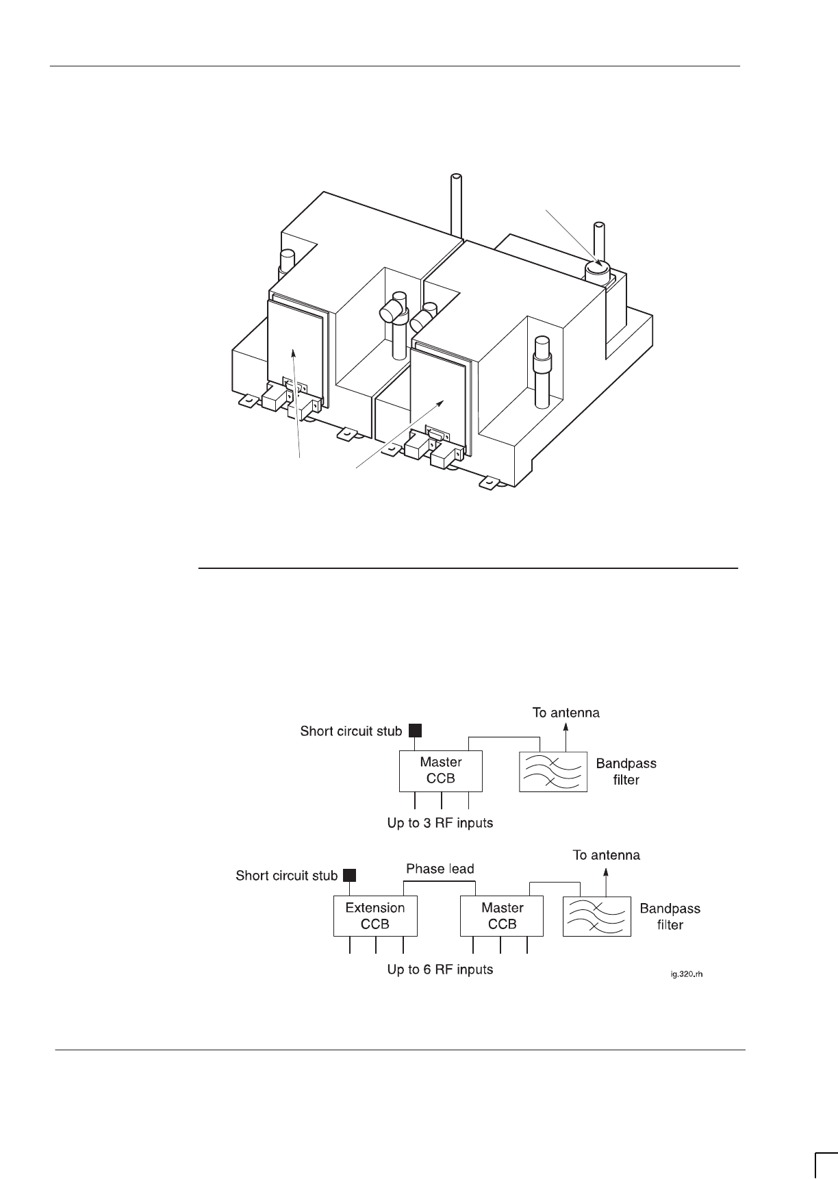
GSM-205-323
CCB
31st Oct 01
Tech. 5–48
Technical Description: Horizon
macro
indoor
CONTROLLED INTRODUCTION
68P02902W07-B
Figure 5-32 shows two DCS1800 CCBs with main and redundant control boards
fitted.
ig.319.rh
CCB CONTROL BOARDS
ANTENNA CONNECTOR
Figure 5-32 DCS1800 CCBs with control boards fitted
CCB
configuration
The master CCB has a second output to enable the extension CCB to be
connected. The bandpass filter can then serve both CCBs in parallel. Any
unused output is terminated with a short circuit stub. The two configurations are
shown in Figure 5-33.
Figure 5-33 CCB configurations
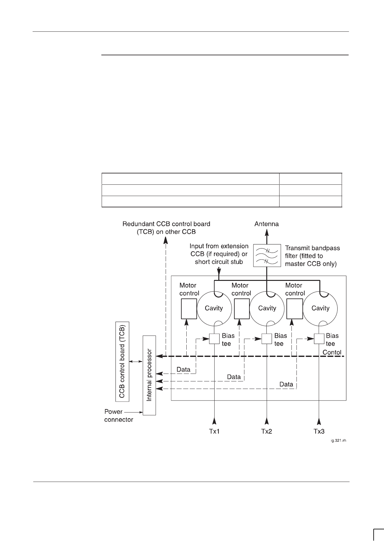
GSM-205-323 CCB
31st Oct 01
Technical Description: Horizon
macro
indoor
68P02902W07-B
CONTROLLED INTRODUCTION
Tech. 5–49
CCB functional
description and
diagram
The CCB has three independently tuneable cavity resonators, as shown in
Figure 5-34. The cavities are narrow band devices which pass transmit signals
at the cavity tuned (resonant) frequency. The three cavity outputs are coupled
together.
The CCB cavities are tuned by software commands from the CCB control board.
Control data is sent from the CTU, via the coaxial cable, to the CCB. This data is
separated from the RF signal at the bias tee, and sent to the CCB control board.
The CCB control board then sends control signals through the control bus to the
motor control of the CCB cavity of the same transceiver.
CCB tuning change Time taken
One cavity retuned and verified 8 seconds
Three cavities retuned and verified 19 seconds
Figure 5-34 Functional diagram of CCB

GSM-205-323
CCB
31st Oct 01
Tech. 5–50
Technical Description: Horizon
macro
indoor
CONTROLLED INTRODUCTION
68P02902W07-B

31st Oct 01
Technical Description: Horizon
macro
indoor
68P02902W07-B
CONTROLLED INTRODUCTION
i
Chapter 6
Digital modules

GSM-205-323
31st Oct 01
ii
Technical Description: Horizon
macro
indoor
CONTROLLED INTRODUCTION
68P02902W07-B

GSM-205-323
31st Oct 01
Technical Description: Horizon
macro
indoor
68P02902W07-B
CONTROLLED INTRODUCTION
iii
Chapter 6
Digital modules i. . . . . . . . . . . . . . . . . . . . . . . . . . . . . . . . . . . . . . . . . . . . . . .
Overview of digital modules Tech. 6–1. . . . . . . . . . . . . . . . . . . . . . . . . . . . . . . . . . . . . . . . . . .
Overview and redundancy Tech. 6–1. . . . . . . . . . . . . . . . . . . . . . . . . . . . . . . . . . . . . . .
Digital module and BPSM locations Tech. 6–1. . . . . . . . . . . . . . . . . . . . . . . . . . . . . . .
MCUF and NIU redundancy Tech. 6–2. . . . . . . . . . . . . . . . . . . . . . . . . . . . . . . . . . . . .
Full size and half size modules Tech. 6–2. . . . . . . . . . . . . . . . . . . . . . . . . . . . . . . . . . .
Digital module and CTU connections Tech. 6–3. . . . . . . . . . . . . . . . . . . . . . . . . . . . . .
Diagram of digital module and CTU connections Tech. 6–3. . . . . . . . . . . . . . . . . . . .
MCUF Tech. 6–4. . . . . . . . . . . . . . . . . . . . . . . . . . . . . . . . . . . . . . . . . . . . . . . . . . . . . . . . . . . . . .
MCUF overview Tech. 6–4. . . . . . . . . . . . . . . . . . . . . . . . . . . . . . . . . . . . . . . . . . . . . . . . .
Capability to replace MCU of M-Cell6 and M-Cell2 Tech. 6–4. . . . . . . . . . . . . . . . . .
GPROC TSW and GLCK functions Tech. 6–5. . . . . . . . . . . . . . . . . . . . . . . . . . . . . . . .
MCUF module view Tech. 6–5. . . . . . . . . . . . . . . . . . . . . . . . . . . . . . . . . . . . . . . . . . . . .
MCUF functional diagram Tech. 6–6. . . . . . . . . . . . . . . . . . . . . . . . . . . . . . . . . . . . . . . .
Link to redundant MCUF Tech. 6–7. . . . . . . . . . . . . . . . . . . . . . . . . . . . . . . . . . . . . . . . .
Front panel interfaces Tech. 6–7. . . . . . . . . . . . . . . . . . . . . . . . . . . . . . . . . . . . . . . . . . .
Front panel switches and indicators Tech. 6–8. . . . . . . . . . . . . . . . . . . . . . . . . . . . . . .
PIX interfaces Tech. 6–9. . . . . . . . . . . . . . . . . . . . . . . . . . . . . . . . . . . . . . . . . . . . . . . . . .
DRAM, flash EPROM and code loading functions Tech. 6–9. . . . . . . . . . . . . . . . . . .
ASIC functionality Tech. 6–10. . . . . . . . . . . . . . . . . . . . . . . . . . . . . . . . . . . . . . . . . . . . . . .
Sync block functionality Tech. 6–11. . . . . . . . . . . . . . . . . . . . . . . . . . . . . . . . . . . . . . . . . .
Integral MCUF FMUX functionality Tech. 6–13. . . . . . . . . . . . . . . . . . . . . . . . . . . . . . . .
NIU Tech. 6–14. . . . . . . . . . . . . . . . . . . . . . . . . . . . . . . . . . . . . . . . . . . . . . . . . . . . . . . . . . . . . . . .
Overview of NIU Tech. 6–14. . . . . . . . . . . . . . . . . . . . . . . . . . . . . . . . . . . . . . . . . . . . . . . .
NIU locations Tech. 6–14. . . . . . . . . . . . . . . . . . . . . . . . . . . . . . . . . . . . . . . . . . . . . . . . . . .
NIU command identity number Tech. 6–14. . . . . . . . . . . . . . . . . . . . . . . . . . . . . . . . . . . .
Module view and LEDs Tech. 6–15. . . . . . . . . . . . . . . . . . . . . . . . . . . . . . . . . . . . . . . . . .
NIU functionality Tech. 6–16. . . . . . . . . . . . . . . . . . . . . . . . . . . . . . . . . . . . . . . . . . . . . . . .
NIU diagram Tech. 6–17. . . . . . . . . . . . . . . . . . . . . . . . . . . . . . . . . . . . . . . . . . . . . . . . . . .
Control processor Tech. 6–18. . . . . . . . . . . . . . . . . . . . . . . . . . . . . . . . . . . . . . . . . . . . . . .
NIU/MCUF framing and clocks Tech. 6–18. . . . . . . . . . . . . . . . . . . . . . . . . . . . . . . . . . . .
Distance measurement Tech. 6–19. . . . . . . . . . . . . . . . . . . . . . . . . . . . . . . . . . . . . . . . . .
Radio signalling links (RSLs) Tech. 6–19. . . . . . . . . . . . . . . . . . . . . . . . . . . . . . . . . . . . .
T1 NIU need to set link type Tech. 6–19. . . . . . . . . . . . . . . . . . . . . . . . . . . . . . . . . . . . . .
T43/BIB-NIU - E1/T1 mapping Tech. 6–20. . . . . . . . . . . . . . . . . . . . . . . . . . . . . . . . . . . . . . . . .
Overview of T43/BIB-NIU connection Tech. 6–20. . . . . . . . . . . . . . . . . . . . . . . . . . . . . .
NIU to T43 mapping and command ID Tech. 6–20. . . . . . . . . . . . . . . . . . . . . . . . . . . . .
Diagram of T43 connection to NIUs Tech. 6–21. . . . . . . . . . . . . . . . . . . . . . . . . . . . . . .
FMUX module Tech. 6–22. . . . . . . . . . . . . . . . . . . . . . . . . . . . . . . . . . . . . . . . . . . . . . . . . . . . . . .
Overview of FMUX module Tech. 6–22. . . . . . . . . . . . . . . . . . . . . . . . . . . . . . . . . . . . . . .
FMUX module view Tech. 6–22. . . . . . . . . . . . . . . . . . . . . . . . . . . . . . . . . . . . . . . . . . . . .
FMUX functional diagram Tech. 6–23. . . . . . . . . . . . . . . . . . . . . . . . . . . . . . . . . . . . . . . .
FMUX functional explanation Tech. 6–23. . . . . . . . . . . . . . . . . . . . . . . . . . . . . . . . . . . . .
Alarm module Tech. 6–24. . . . . . . . . . . . . . . . . . . . . . . . . . . . . . . . . . . . . . . . . . . . . . . . . . . . . . .
Alarm module overview Tech. 6–24. . . . . . . . . . . . . . . . . . . . . . . . . . . . . . . . . . . . . . . . . .
Alarm module view Tech. 6–24. . . . . . . . . . . . . . . . . . . . . . . . . . . . . . . . . . . . . . . . . . . . . .
Alarm module functionality Tech. 6–25. . . . . . . . . . . . . . . . . . . . . . . . . . . . . . . . . . . . . . .
Alarm module replacement – effect on alarms Tech. 6–25. . . . . . . . . . . . . . . . . . . . . .
Alarm collection from extension cabinets Tech. 6–25. . . . . . . . . . . . . . . . . . . . . . . . . . .
Alarm module display presentation Tech. 6–26. . . . . . . . . . . . . . . . . . . . . . . . . . . . . . . .

GSM-205-323
31st Oct 01
iv
Technical Description: Horizon
macro
indoor
CONTROLLED INTRODUCTION
68P02902W07-B
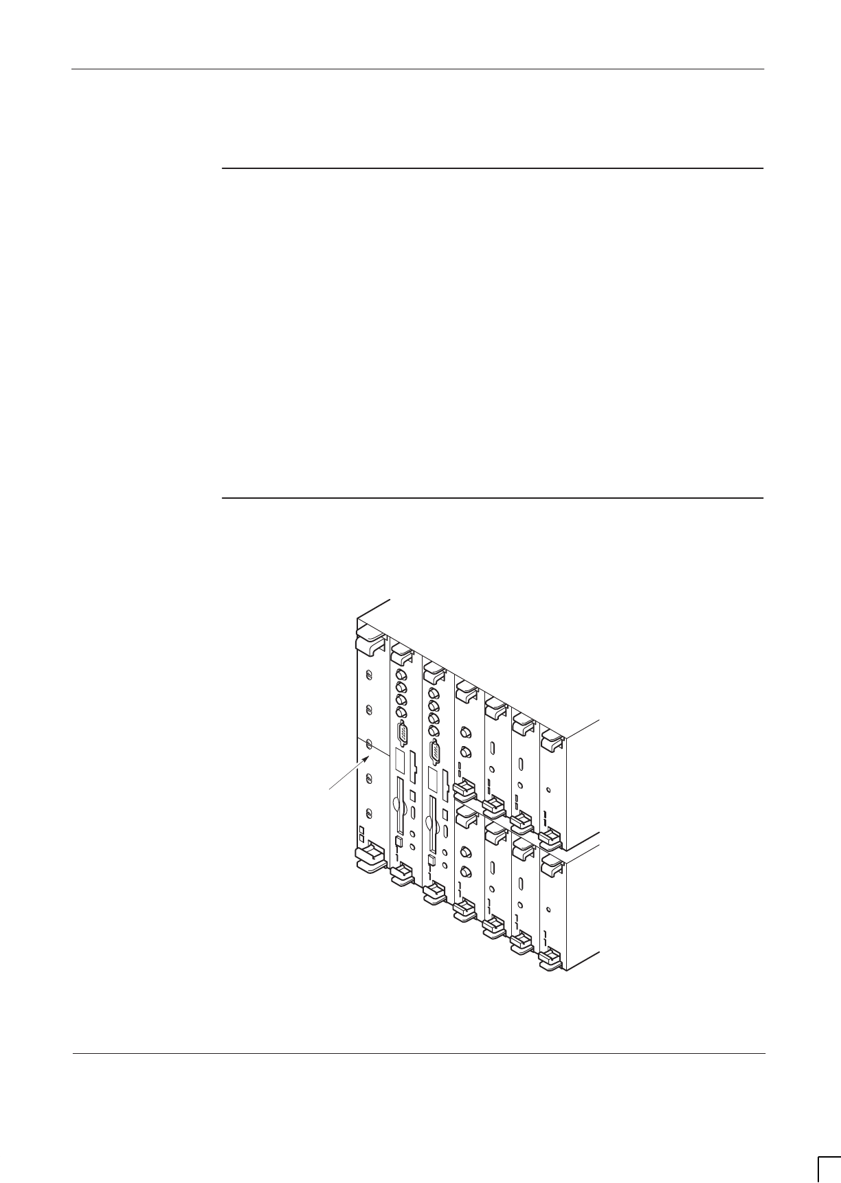
GSM-205-323 Overview of digital modules
31st Oct 01
Technical Description: Horizon
macro
indoor
68P02902W07-B
CONTROLLED INTRODUCTION
Tech. 6–1
Overview of digital modules
Overview and
redundancy
Digital modules provide the Horizon
macro
indoor equivalent of M-Cell
6
micro
base control unit (µBCU) functionality. They are located in the bottom right side
of the CIBA maincage, and are electronically interconnected through the
backplane. Fibre optic connections are at the front of the appropriate modules.
Each digital module is assigned A (master) or B (redundant), with one BPSM
(µBCU Power Supply Module) for A and one BPSM for B. The alarm module is
not assigned to A or B, as it is supplied by both BPSMs for redundancy.
The master MCUF is assigned to A, and the redundant MCUF to B, each with
an associated FMUX.
The four NIUs are used by the operational MCUF, but two NIUs are powered by
BPSM A and two NIUs by BPSM B.
All slots are annotated with the legend of the appropriate module and located as
shown in Figure 6-1.
Digital module
and BPSM
locations
Figure 6-1 shows the position of modules within the digital module shelf.
ig.322.rh
ALARM
MODULE
NIU B0
NIU B1
BPSM
BPSM
FMUX
FMUX
MCUF A
MCUF B
NIU A0
NIU A1
REDUNDANT (B)
MASTER (A)
DIGITAL
MODULE SHELF
Figure 6-1 Digital and BPSM module locations, including optional redundancy

GSM-205-323
Overview of digital modules
31st Oct 01
Tech. 6–2
Technical Description: Horizon
macro
indoor
CONTROLLED INTRODUCTION
68P02902W07-B
MCUF and NIU
redundancy
The digital module shelf can:
SSupport two MCUFs at a BTS site, one master and one slave (for
redundancy).
SEnable Master MCUF failure to result in the slave MCUF becoming the
master after reset.
SEnable the OMC-R operator to initiate master/slave MCUF swap.
SConfigure CTUs by the master MCUF.
All four NIUs operate from the master MCUF, but each pair of NIUs depend on a
BPSM for power. All NIUs configure to the master MCUF clock.
NOTE When fitting a replacement redundant MCUF, care must
be taken to ensure firmware compatibility with the master
MCUF. Firmware incompatibility may result in a loss of
communication between the two MCUFs so that the
redundant MCUF is not in a position to take control in the
event of a failure of the master MCUF.
Full size and
half size
modules
Modules are full size and half size, as shown in Table 6-1.
Table 6-1 Full size and half size digital modules
Full size modules Half size modules
Main Control Unit with dual FMUX (MCUF) Network interface unit (NIU)
Alarm module Fibre optic multiplexer (FMUX)
BPSM (µBCU Power Supply
Module)
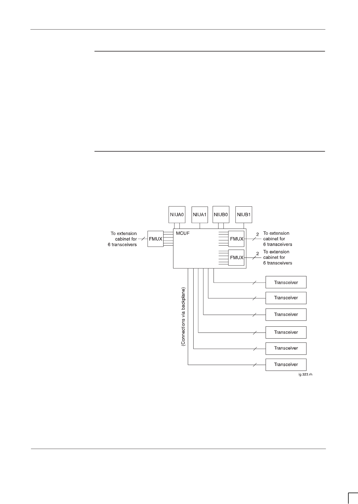
GSM-205-323 Overview of digital modules
31st Oct 01
Technical Description: Horizon
macro
indoor
68P02902W07-B
CONTROLLED INTRODUCTION
Tech. 6–3
Digital module
and CTU
connections
The MCUF is connected to the CTUs in the same cabinet through the
backplane. Optional connection to CTUs in up to three additional cabinets (six
CTUs per cabinet) is by fibre optic links. FMUXs, two internal to the MCUF and
one half size module, convert the electronic data stream into a fibre optic signal.
An FMUX module in each extension cabinet converts the fibre optic signal back
to electronic data stream, for transmission to CTUs via the backplane.
The NIU modules convert signals for terrestrial E1 or T1 lines.
Diagram of
digital module
and CTU
connections
Figure 6-2 shows a block diagram of the digital module and CTU connections.
Figure 6-2 Digital module and CTU connections

GSM-205-323
MCUF
31st Oct 01
Tech. 6–4
Technical Description: Horizon
macro
indoor
CONTROLLED INTRODUCTION
68P02902W07-B
MCUF
MCUF overview
The main control unit with dual FMUX(MCUF) provides the site processing
functions, apart from RF functions of the transceiver. The MCUF also provides
switching for up to six network interfaces (via four NIUs) and up to 24
transceivers.
The cabinet may contain up to two MCUF modules, (one master and one for
redundancy). Each site and module has an electronic ID for remote
identification.
The MCUF provides the following functions:
SMaintenance and operational/control processing.
SCall processing (for example resource management and switching of
baseband hopping data).
SSwitching of traffic and control information.
STiming reference and network/BTS master clock synchronization.
SThe functionality of two FMUX.
SSupport of up to six transceivers via backplane in first cabinet and up to an
additional 18 transceivers via FMUX connections to other cabinets.
SSupport of up to six E1 or T1 circuits, via NIU modules.
SSupport of the CSFP function via the PCMCIA flash memory card.
Capability to
replace MCU of
M-Cell
6
and
M-Cell
2
The MCUF combines the MCU function of M-Cell
6
with two FMUX modules. If
the MCUF is installed in an M-Cell
6
or M-Cell
2
the MCUF automatically reverts
to the functionality of an MCU. The internal FMUX devices no longer operate. In
M-Cell
2
the reversion to MCU mode includes ability to directly connect to two
transceivers by modified use of the front panel FMUX fibre optic connections.
NOTE This capability to use MCUF in M-Cell
6
and M-Cell
2
is only
possible with GSR4 or later.
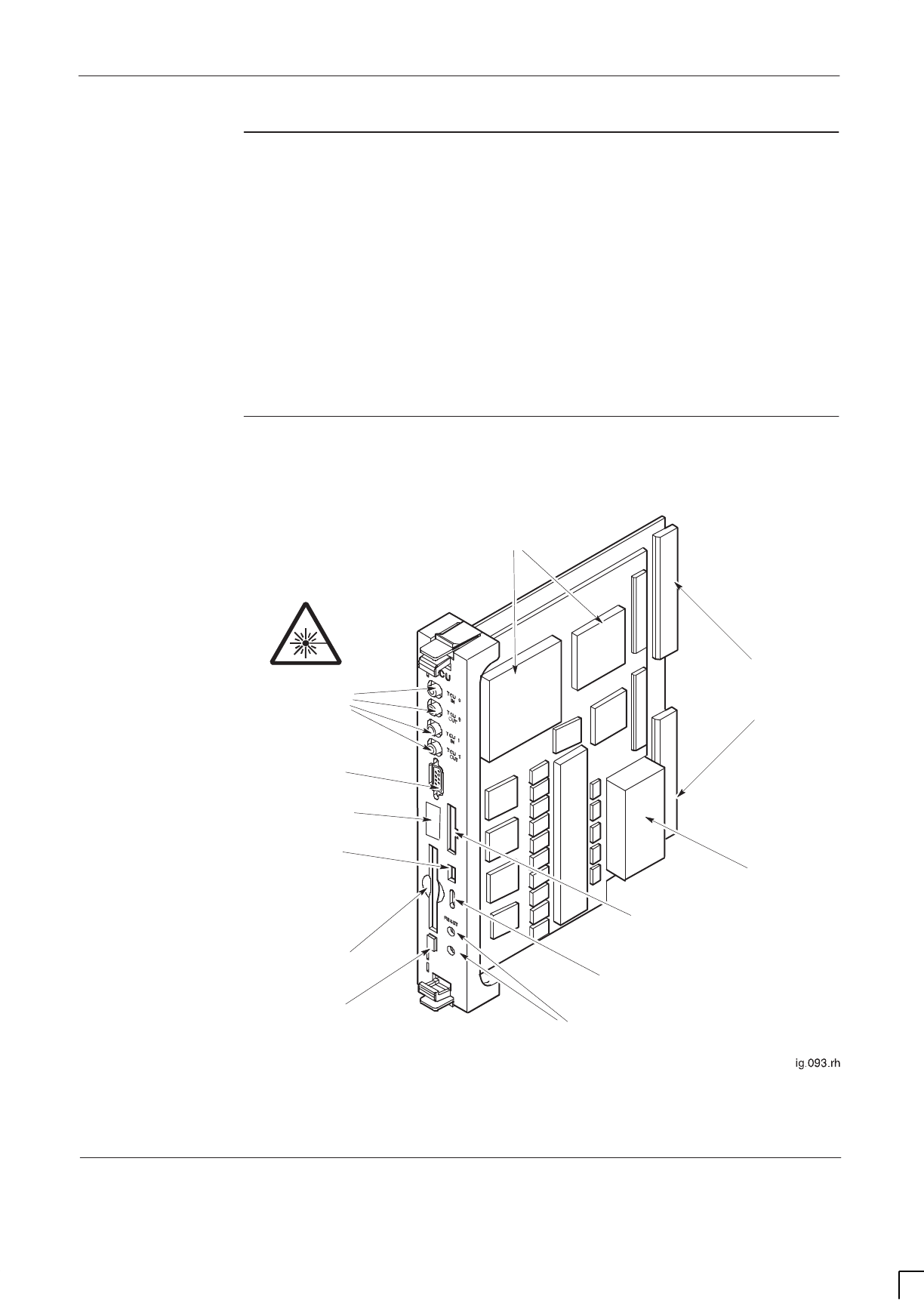
GSM-205-323 MCUF
31st Oct 01
Technical Description: Horizon
macro
indoor
68P02902W07-B
CONTROLLED INTRODUCTION
Tech. 6–5
GPROC TSW
and GLCK
functions
The MCU section of the MCUF module combines functions of older generation
equipment:
SThe BTP (Base Transceiver Processor) functions and CSFP (Code
Storage Facility Processor) functions (provided PCMCIA card fitted),
formerly achieved by generic processor boards (GPROCs).
SThe timeslot switch (TSW).
SThe generic clock (GCLK).
MCUF module
view
Figure 6-3 shows an MCUF module.
(FULL - REMOVES SOFTWARE FROM MEMORY
CPU – RESETS MCUF CPU)
PCMCIA
CARD SLOT STATUS LEDS (RED &
GREEN)
CAL PORT
TTY MMI
PROCESSORS
OSCILLATOR
DEBUG PORT
BDM PORT
RESET BUTTONS
PCMCIA EJECT
BUTTON
INTERNAL FMUX
FIBRE OPTIC
CONNECTIONS
BACKPLANE
CONNECTORS
Figure 6-3 View of the MCUF
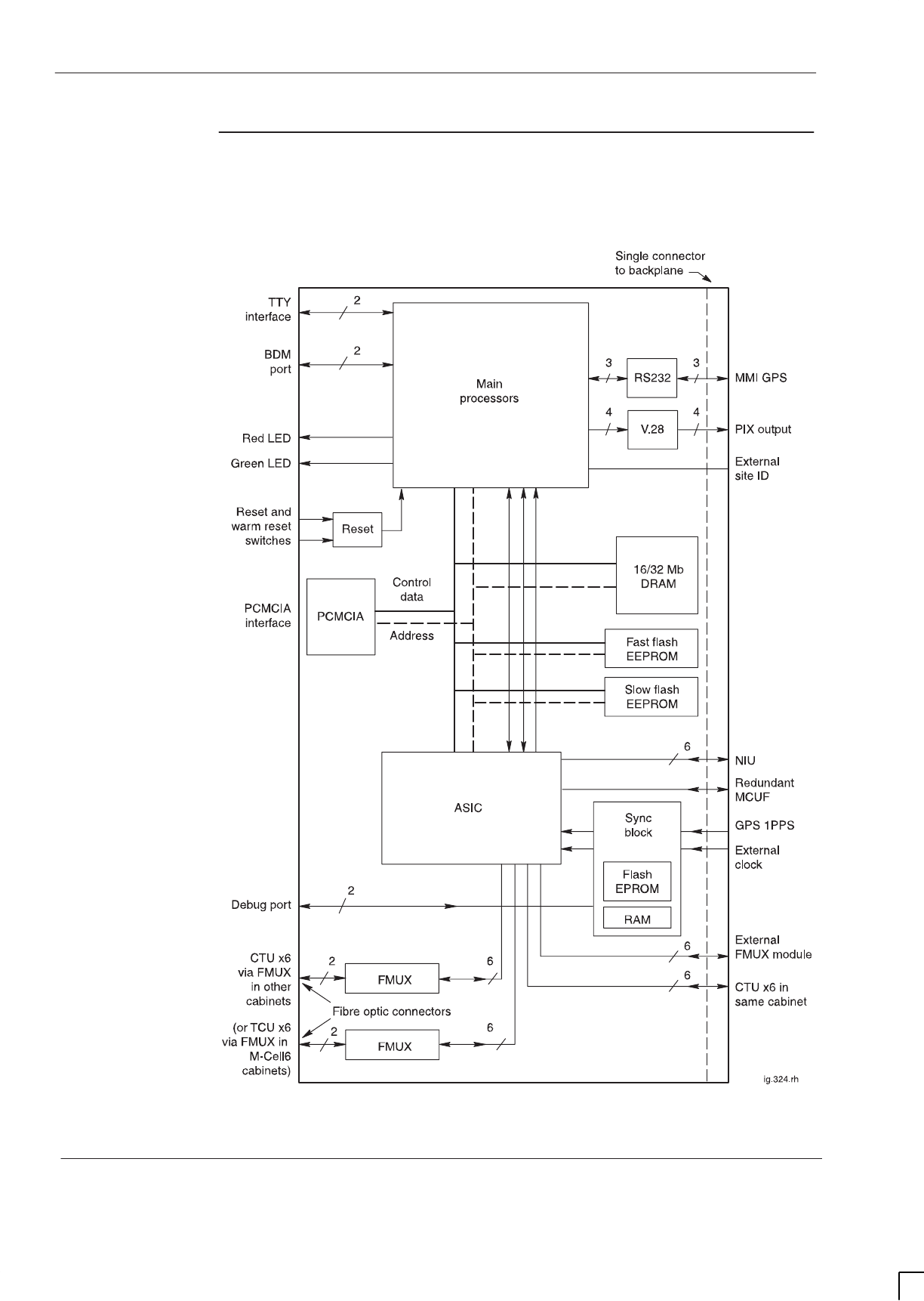
GSM-205-323
MCUF
31st Oct 01
Tech. 6–6
Technical Description: Horizon
macro
indoor
CONTROLLED INTRODUCTION
68P02902W07-B
MCUF
functional
diagram
Figure 6-4 shows a functional diagram of the MCUF.
(IF USED)
(IF USED)
Figure 6-4 Functional diagram of MCUF in MCUF mode

GSM-205-323 MCUF
31st Oct 01
Technical Description: Horizon
macro
indoor
68P02902W07-B
CONTROLLED INTRODUCTION
Tech. 6–7
Link to
redundant
MCUF
The link to the redundant MCUF is similar to a transceiver link, but does not
have the BBH capability, or the link delay measurement and compensation
facility. The 6.12 s, and 60 ms signals, are inserted into timeslots 8 and 16.
When the MCUF is in slave mode, timeslot and E1/T1 clock information is
extracted from the MCUF link and passed to the sync block.
The main processor HDLC link to the redundant MCUF can be routed in any
unused timeslot(s) of this link.
The ASIC can switch any timeslot on the redundancy link to any timeslot on any
of the other links connected to it such as the transceiver links, network links,
redundancy link or processor links.
Front panel
interfaces
TTY interface
A standard TTY interface is provided on the front panel, of 9.6 kbit/s (8 bits, no
parity, 1 stop bit (8 N 1)). A local maintenance terminal can be attached to this
port to use the MMI (Man Machine Interface) of the MCUF.
Debug and BDM ports
Two front panel ports are for Motorola factory and development use only:
SThe debug port, consists of a TTY connection to the sync processor to
access sync firmware, together with other connections to the ASIC and
main processors.
SThe Background Debug Mode (BDM) port is used for low level debugging
of the main processors.
FMUX fibre optic connections
There are fibre optic connections from the MCUF internal FMUX modules. The
fibre optic connectors enable connection to FMUX modules in other cabinets for
additional transceivers.
CAL port
The CAL port on the front panel of the MCUF can be used to calibrate the sync
block clock via MMI commands. The 8 kHz reference output is used in GCLK
calibration procedure (see
Installation & Configuration BSS Optimization
(GSM-100-423)
).

GSM-205-323
MCUF
31st Oct 01
Tech. 6–8
Technical Description: Horizon
macro
indoor
CONTROLLED INTRODUCTION
68P02902W07-B
PCMCIA interface
The PCMCIA card is located on the front panel of the MCUF, and is used for:
SCode Storage Facility Processor (CSFP) memory.
SRapid site initialization.
The PCMCIA socket is an industrial standard 68 pin single socket, fitted with an
ejector. The PCMCIA interface supports rev 2.1 type I and II cards.
The 20 Mbyte card can be write enabled, for upgrade of site information, or
disabled to protect card use for other sites or secure the site code.
Front panel
switches and
indicators
The front panel of the MCUF module has two reset switches as shown in
Figure 6-3:
SFULL is a hard reset (power up - removes software from the memory).
SCPU is a soft reset (this resets the MCUF main processors, but the
software remains in RAM).
A hard reset results in the software being reloaded to the DRAM in the same
way as normal power up.
NOTE During the CPU (soft) reset, pressing CPU reset again will
perform a hard reset. Pressing the CPU reset button twice
thus has the same effect as a hard reset.
The MCUF has two front panel LEDs (one green and one red) as shown in
Figure 6-3, with indications as shown in Table 6-2.
CAUTION When red and green LEDs are flashing, the boot code is
downloading into non-volatile memory for software
upgrade. Do not remove power or reset the cabinet until
downloading has been completed, as this will corrupt the
non-volatile memory. If boot code is corrupted, contact the
Motorola Customer Network Resolution Centre, requesting
the boot code restoration procedure and the appropriate
boot code file.
Table 6-2 MCUF front panel LED indication
Red Green Status
Off Off Board not powered up or in rest cycle
Off On Normal operation
On Off Fault condition
Flashing Flashing Non-volatile memory boot code upgrade
(Do not remove power nor reset – see CAUTION)

GSM-205-323 MCUF
31st Oct 01
Technical Description: Horizon
macro
indoor
68P02902W07-B
CONTROLLED INTRODUCTION
Tech. 6–9
PIX interfaces
The MCUF provides four PIX outputs on the backplane, driven at V. 28 levels.
The four PIX outputs, routed to the cabinet alarm board, enable relay contact
control of external customer equipment.
DRAM, flash
EPROM and
code loading
functions
DRAM
The 16 Mbyte DRAM provides operational code and data storage for the main
processors. There is also a SIMM socket in the circuit board, enabling the
addition of a further 16 Mbytes if required. After software initialization, the DRAM
uses ECC protection. Memory protection is provided by the main processors.
Fast flash EPROM
The fast flash 1 Mbyte bank is used for bootcode and executive process code. It
has a fast access time (<75 ns), enabling direct execution. The bootcode is
factory set, and reprogrammed only in major software upgrades.
Slow flash EPROM
The slow flash 0.5 Mbyte bank is used for non-volatile data storage of diagnostic
data and module ID information.
Code loading
The boot and executive code, held in the fast flash EPROM, initiates the MCUF
on power up or reset. If a PCMCIA memory card is fitted, operational code may
be obtained and copied to the DRAM for execution. If no card or code is
available, the operational code is obtained from the BSC.
Before execution, the operational code held in DRAM is checked with code held
at the BSC. The BSC downloads any changed code objects to the DRAM.
After successful checking of the DRAM operational code, the code is executed,
and the PCMCIA memory card updated with any changed objects.
CSFP code loading
If a PCMCIA memory card is available,then a code storage facility processor
(CSFP) function can be supported. A new software load can be downloaded in
the background, without any reduction in service, and stored on the PCMCIA
card.
Once the complete load has been transferred to the PCMCIA card, a code swap
can be initiated. The site is reset and the new software brought into service (<10
minutes). As a precaution, the old version is held on the PCMCIA card to
support a roll back to the original version if required.

GSM-205-323
MCUF
31st Oct 01
Tech. 6–10
Technical Description: Horizon
macro
indoor
CONTROLLED INTRODUCTION
68P02902W07-B
ASIC
functionality
The Application Specific Integrated Circuit (ASIC) provides central switching
capabilities for the MCUF. It is capable of supporting up to 24 transceivers,
together with up to six network interfaces and two links to the on-board
processors, one link to the sync processor and a link to the redundant MCUF.
The link to the sync processor is used for code loading purposes only. The
ASIC supports baseband hopping across the 24 transceiver links.
The ASIC provides interface features associated with the transceiver links,
these include synchronization features to allow for delay in the link to the
transceivers, and the necessary framing and encoding to support the link.
All of the serial links into the ASIC are internal lines (I lines), 125 ms framed,
with 32 eight bit timeslots per frame.
ASIC transceiver link features
The ASIC interfaces to a maximum of 24 transceiver links. The ASIC can switch
any timeslot on any of the transceiver links to any timeslot on other links
connected to the ASIC; transceiver links, network links, MCUF redundancy link
or processor links.
The ASIC provides the following features associated with the transceiver links:
SLink advance/delay compensation.
The ASIC will continually measure the round trip delay on each transceiver
link to calculate a timing advance for each link. The link advance is
applied, and can be adjusted, by the main processor via the processor
parallel interface.
SBBH data switching.
BBH switching is performed automatically on any timeslot configured as
BBH data. A single timeslot from the transceiver is selected for BBH
routeing information, and defines which transceiver link (0-23) should be
used for downlink.
STiming reference insertion.
The ASIC receives timing pulses from the sync block and inserts the
appropriate bits into the transceiver downlink synchronization and framing
timeslots. The sync block will provide a version of the 6.12 s and 60 ms
signals that is advanced by 125 ms for this purpose.
SManchester coding/decoding.
The transceiver links are all Manchester coded/decoded by the ASIC. This
function can be switched on or off (default on) on a per link basis. The
disable feature is for applications outside of the MCUF module.

GSM-205-323 MCUF
31st Oct 01
Technical Description: Horizon
macro
indoor
68P02902W07-B
CONTROLLED INTRODUCTION
Tech. 6–11
ASIC/network and processor link switching
The ASIC supports a maximum of six network links and two main processor
links. The data to/from these links can be switched to/from any timeslot on other
links connected to the ASIC.
The two links to the main processor allow it to route HDLC and other links to the
appropriate place:
S24 HDLC timeslots for the BCF RSS channel to each transceiver.
SFour timeslots for NIU control channels (two local, two redundant).
SSync processor code load channel.
STwo channels for RSL links.
SOne HDLC channel occupying up to three timeslots to the redundant
MCUF.
Sync block
functionality
The sync block is controlled via the parallel interface of the main processors.
The sync block is responsible for site synchronization functions. It generates all
required local references from a high stability local clock source. This clock
source may also be locked to the incoming network clocks.
The sync clock source is in the form of a crystal oscillator (OCXO) which warms
up for phase locking in 4 minutes, and achieves frequency stabilization in 15
minutes.
Site frame reference generation and re-timing includes:
S2.048 MHz - For serial communications.
S16.384 MHz - For FMUX communications.
S125 ms - For NIU framing and transceiver framing.
S60 ms- For transceiver GSM timing.
S6.12 s - For GSM superframe.
The reference clocks available to the sync block are:
SSix network extracted clocks (E1/T1 source via NIUs). Any of the NIU
modules under control of the MCUF can extract a reference clock from an
E1/T1 link and pass to the Sync block.
SCAL port. The CAL port can be used to calibrate the sync block clock via
MMI commands. The reference output provides a monitoring point.
SRedundant MCUF link.

GSM-205-323
MCUF
31st Oct 01
Tech. 6–12
Technical Description: Horizon
macro
indoor
CONTROLLED INTRODUCTION
68P02902W07-B
Phase lock loop (PLL) operating modes
The PLL uses the selected reference signal as the loop reference clock. It
includes an OCXO accurate to 0.05 ppm, a phase comparator and a loop filter.
The PLL has the following operating modes:
SWarm-up
The PLL is open loop and using the calibration frequency, but the OCXO
is not yet warmed up.
SSet frequency
The PLL is open loop and using the calibration frequency, and the OCXO
is warmed up.
SFast tune
Closed loop with wide filter for coarse locking to the reference (extracted
from network clock).
SFine tune
Closed loop with narrow filter for accurate locking to the reference
(extracted from network clock).
When in fine tune closed loop mode, the accuracy is 0.01 ppm.
Sync block code load
The sync block controller has a dedicated 2.048 Mbit/s serial link into the ASIC
enabling a 64 kbit/s HDLC channel to the main processors for code loading.
The sync block includes 256 kbytes of flash EPROM used to store:
SBoot code.
SOperational code.
The boot code, which cannot be altered, queries the main processors on the
current version of the sync operational code.
If the stored operational code is the correct version, the boot code will move the
operational code to RAM and execute the code.
If the query results in the need for new operational code, the sync processor will
download the operational code from the main processors via the ASIC to the
RAM in the sync block.
After a successful download, the boot code programmes the flash EPROM with
the new operational code and runs the operational code in RAM.
GSM counters
The following counters are provided:
SGSM frame incremented every 4.615 ms, range 0 to 1325.
SGSM superframe incremented every 6.12 s, range 0 to 2047.

GSM-205-323 MCUF
31st Oct 01
Technical Description: Horizon
macro
indoor
68P02902W07-B
CONTROLLED INTRODUCTION
Tech. 6–13
Integral MCUF
FMUX
functionality
The equivalent function of two FMUX modules exists integral to the MCUF,
enabling two extension cabinets to be connected. To enable total of four
cabinets to be joined together as one BTS site, an FMUX module is also
required in the master cabinet to connect the third extension cabinet. A single
cabinet site has no need for the FMUX functionality, because the MCUF
connects with the cabinet CTUs through the backplane.
Each fibre optic multiplexer (FMUX) function multiplexes and demultiplexes six,
full duplex, transceiver links to one (TX/Rx) pair of fibre optic cables. This
enables up to six transceivers in a single extension cabinet (either
Horizon
macro
or M-Cell
6
) to be linked to the master cabinet.
Each FMUX fibre optic link is full duplex 16.384 Mbit/s. The FMUX optical link is
capable of driving up to 1 km.
For functional description of FMUX see FMUX module and FMUX function in
this chapter.

GSM-205-323
NIU
31st Oct 01
Tech. 6–14
Technical Description: Horizon
macro
indoor
CONTROLLED INTRODUCTION
68P02902W07-B
NIU
Overview of NIU
The network interface unit (NIU) module provides two E1 or two T1 termination
links to the terrestrial network. The NIU E1/T1 outputs are connected to a T43 or
BIB board, depending on the impedance matching requirement of the customer
terrestrial circuits.
There are two types of NIU board, one for E1, one for T1. The NIU layout is
common to both E1 and T1, the only differences being in the associated crystal
oscillators and line matching resistor values.
An on-board NIU control processor provides network interface configuration and
supervision, controlled by the MCUF.
NIU locations
The cabinet may contain up to four NIU modules in the digital module shelf, as
shown in Figure 6-1. Two NIUs are located in the master (lower) part of the
shelf. Two NIUs are in the redundant (upper) part of the shelf, though these
upper NIUs are also used for non-redundant purposes.
An NIU in slot A0 supports two E1/T1 links.
An NIU in slot A1 supports one E1/T1 link.
An NIU in slot B0 supports two E1/T1 links.
An NIU in slot B1 supports one E1/T1 link.
NIU command
identity number
Each NIU is identified in the database by an identity number, from 0 to 3.
Table 6-3 shows the NIU slots and equivalent identity number.
Table 6-3 NIU slot and equivalent command identity
NIU (MSI) identity number
used in commands NIU slot
0 A0
1 B0
2 A1
3 B1
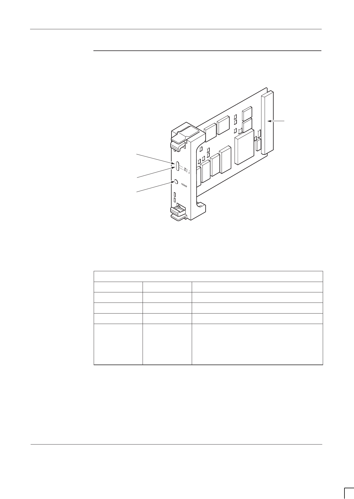
GSM-205-323 NIU
31st Oct 01
Technical Description: Horizon
macro
indoor
68P02902W07-B
CONTROLLED INTRODUCTION
Tech. 6–15
Module view
and LEDs
Figure 6-5 shows an NIU module.
ig.325.rh
RESET/DISABLE
SWITCH
NIU GREEN LED
BACKPLANE
CONNECTOR
NIU RED LED
Figure 6-5 View of NIU module
The NIU status is indicated by the two front panel LEDs, one green and one red,
controlled by the on-board processor, as shown in Table 6-4.
Table 6-4 NIU LED display
Red LED Green LED Status of NIU board
Off Off NIU not powered up or in reset cycle.
Off On Normal operation.
Flashing Flashing NIU undergoing system code download.
On On NIU self testing following switch on or
reboot.
Red LED extinguishes after 20 seconds, or
after 50 seconds following a reboot due to
code download.

GSM-205-323
NIU
31st Oct 01
Tech. 6–16
Technical Description: Horizon
macro
indoor
CONTROLLED INTRODUCTION
68P02902W07-B
NIU
functionality
The NIU provides two E1/T1 interfaces into the network (link 0 and link 1) as
well as LAPD encoding/decoding and clock recovery from a selected E1/T1 link.
The second E1/T1 interface (link 1) is not used for NIUs placed in positions at
A1 and B1, as shown in Figure 6-1.
An NIU control processor provides network interface configuration and
supervision, controlled by the MCUF. The NIU control processor maintains two
independent control links in the redundant configuration (one to each MCUF),
each using timeslot 0 of MCUF link 0.
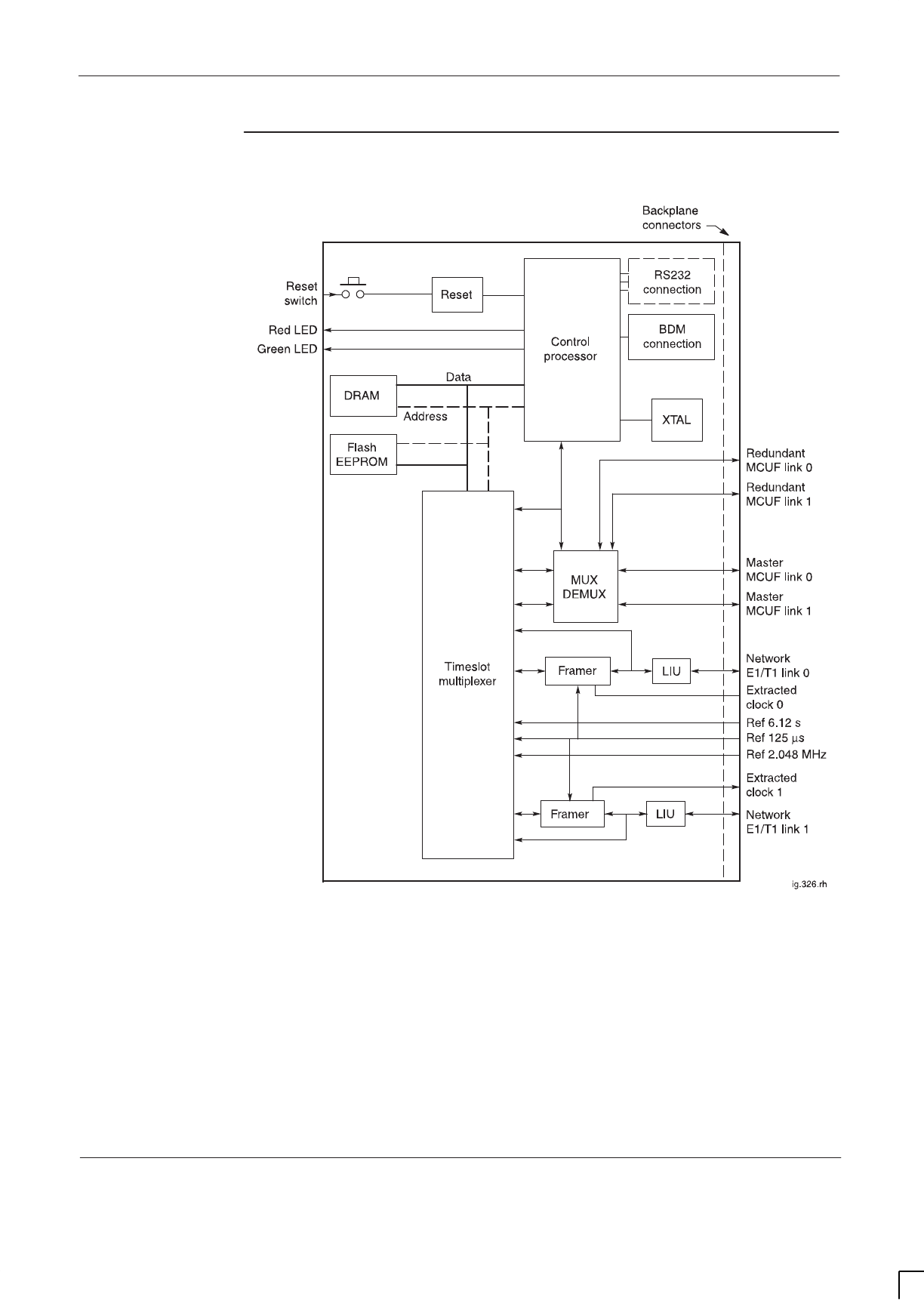
GSM-205-323 NIU
31st Oct 01
Technical Description: Horizon
macro
indoor
68P02902W07-B
CONTROLLED INTRODUCTION
Tech. 6–17
NIU diagram
Figure 6-6 identifies the functional blocks in the NIU.
Figure 6-6 Functional diagram of NIU module

GSM-205-323
NIU
31st Oct 01
Tech. 6–18
Technical Description: Horizon
macro
indoor
CONTROLLED INTRODUCTION
68P02902W07-B
Control
processor
The control processor interfaces to timeslot 0 of link 0 from each connected
MCUF.
The processor uses 512 kbytes of flash EPROM for boot code. operational code
storage and module ID. Code is executed directly from the Flash EPROM. The
boot code can be overwritten under control of the MCUF, if required.
The processor also has an on-chip 1 Mbyte of DRAM.
TTY ports
The processing section provides two TTY ports for Motorola debugging
purposes only.
Resets
The processor is capable of soft resetting itself. The front panel reset causes a
hard reset of the entire board. Power-on also resets the processor.
The MCUF is able to reset the NIU via a message on the HDLC link.
NIU/MCUF
framing and
clocks
The control processor is supplied with a clock from an on-board crystal
oscillator, which has an output enable pad for test purposes. The framer
devices also have their own crystal oscillators on-board.
The framer devices provide the decoded and jitter attenuated receive data, for
passing to the MCUF.
The framer devices also extract a clock signal from an E1/T1 link, which is then
passed to the MCUF synchronization circuit. At the MCUF, this signal is used to
phase lock a local 16.384 MHz clock signal. Once phase locked, three reference
clock signals are provided for NIU use:
SREF 2.048 MHz clock signal.
SREF 6.12 s clock signal.
SREF 125 ms clock signal.
The NIU transmit and receive framing is controlled by this 125 ms reference
pulse received from the MCUF.

GSM-205-323 NIU
31st Oct 01
Technical Description: Horizon
macro
indoor
68P02902W07-B
CONTROLLED INTRODUCTION
Tech. 6–19
Distance
measurement
The NIU provides the ability to perform network distance delay measurement on
either of the two network links. Measurement can only be performed on one link
at a time.
Three modes of operation are possible:
SMode 1. A pattern is transmitted in a selected network timeslot and the
corresponding receive timeslot is monitored for its return. The delay is
measured to an accuracy of ± 488 ns. The pattern is transmitted on the
6.12 second reference signal.
SMode 2. The receive link is monitored for the pattern. When received the
pattern is transmitted back in the next frame. The time between receipt
and transmission of the pattern is measured to an accuracy of ± 488 ns.
SMode 3. The receive link is monitored for the pattern. When it is detected
a strobe is generated for the MCUF sync block.
Radio signalling
links (RSLs)
The radio signalling links (RSL) to the BSC from the main processor on the
MCUF are 64 kbit/s LAPD links. The LAPD encoding of this RSL data is
performed on the NIU by the NIU control processor.
The RSL links between the MCUF and NIU must be sent as follows:
SRSL link 1 is embedded in the NIU control link; that is, it will be in timeslot
0 of link 0 to the NIU. This link is important for initialization.
NOTE When the NIU is on a network link to a BSC or another
BTS, the RSL can be placed on either link on any default
timeslot other than zero.
SRSL link 2 is on a different timeslot from that used for the network
connection.
The NIU supports a maximum of two RSL links. The RSL links may both be on a
single network link or shared between the two network links.
The NIU hardware supports switching for 64 k and 16 k LAPD channels.
T1 NIU need to
set link type
T1 NIUs and E1 NIUs cannot be interchanged. A T1 link line consists of 24
timeslots as opposed to 32 timeslots for an E1 link line. A T1 link generates
specific T1 alarms, referred to as Red alarms. A T1 NIU supports the same MSI
type of device transitions as an E1 NIU.
The OMC-R operator should set the link type or it will default the site to an E1
system. In ROM it is set by a ROM-only MMI command. In RAM it is a database
parameter set by a chg_element command.
The RSL default timeslots are the same for a T1 NIU and an E1 NIU. The basic
mechanism for communicating and configuring is also the same.

GSM-205-323
T43/BIB-NIU - E1/T1 mapping
31st Oct 01
Tech. 6–20
Technical Description: Horizon
macro
indoor
CONTROLLED INTRODUCTION
68P02902W07-B
T43/BIB-NIU - E1/T1 mapping
Overview of
T43/BIB-NIU
connection
The NIU network interface (E1/T1) links connect to a single T43 (CIM) or BIB
(BIM) board on top of the cabinet by a single backplane connector and cable.
NIU to T43
mapping and
command ID
Only six network interfaces are used, three pairs to the master NIU modules,
and three pairs to the redundant NIU modules. Each NIU is identified in the
database by an identity number, from 0 to 3, as shown in the final column of
Table 6-5.
NOTE The redundant NIU modules are only redundant in the
sense of being supplied by a different BPSM, and can
thus continue to operate if the master BPSM fails. All NIUs
are available for separate use.
Table 6-5 defines the mapping from the T43/BIB connector to NIU boards.
Table 6-5 T43/BIB connector to NIU boards
T43 network
side
connector
37-way D-type
connections
(BIB)
NIU location NIU identity
(MSI)
used in commands
J1 1,20 NIU A0 - Tx1 MSI(NIU) 0
J2 2,21 NIU A0 - Rx1
J7 7,26 NIU A0 - Tx2 MSI(NIU) 0
J8 8,27 NIU A0 - Rx2
J13 13,32 NIU A1 - Tx1 MSI(NIU) 2
J14 14,33 NIU A1 - Rx1
J4 4,23 NIU B0 - Tx1 MSI(NIU) 1
J5 5,24 NIU B0 - Rx1
J10 10,29 NIU B0 - Tx2 MSI(NIU) 1
J11 11,30 NIU B0 - Rx2
J16 16,35 NIU B1 - Tx1 MSI(NIU) 3
J17 17,36 NIU B1 - Rx1
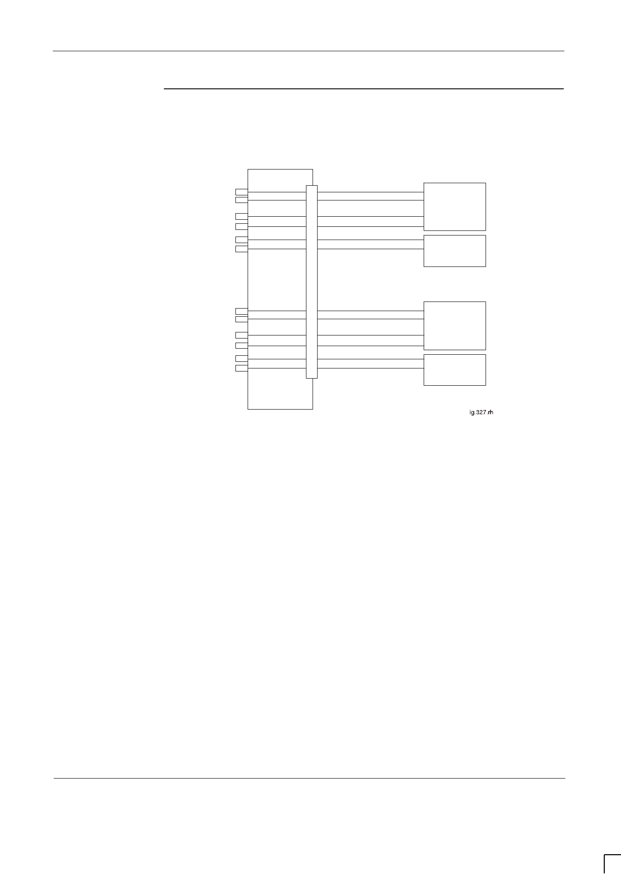
GSM-205-323 T43/BIB-NIU - E1/T1 mapping
31st Oct 01
Technical Description: Horizon
macro
indoor
68P02902W07-B
CONTROLLED INTRODUCTION
Tech. 6–21
Diagram of T43
connection to
NIUs
Figure 6-7 shows a diagram of T43 connection to NIUs.
NIU A0
J0
T43
NIU A1
NIU B0
NIU B1
J1
J2
J7
J8
J13
J14
J4
J5
J10
J11
J17
J16
Figure 6-7 Diagram of T43 connection to NIUs
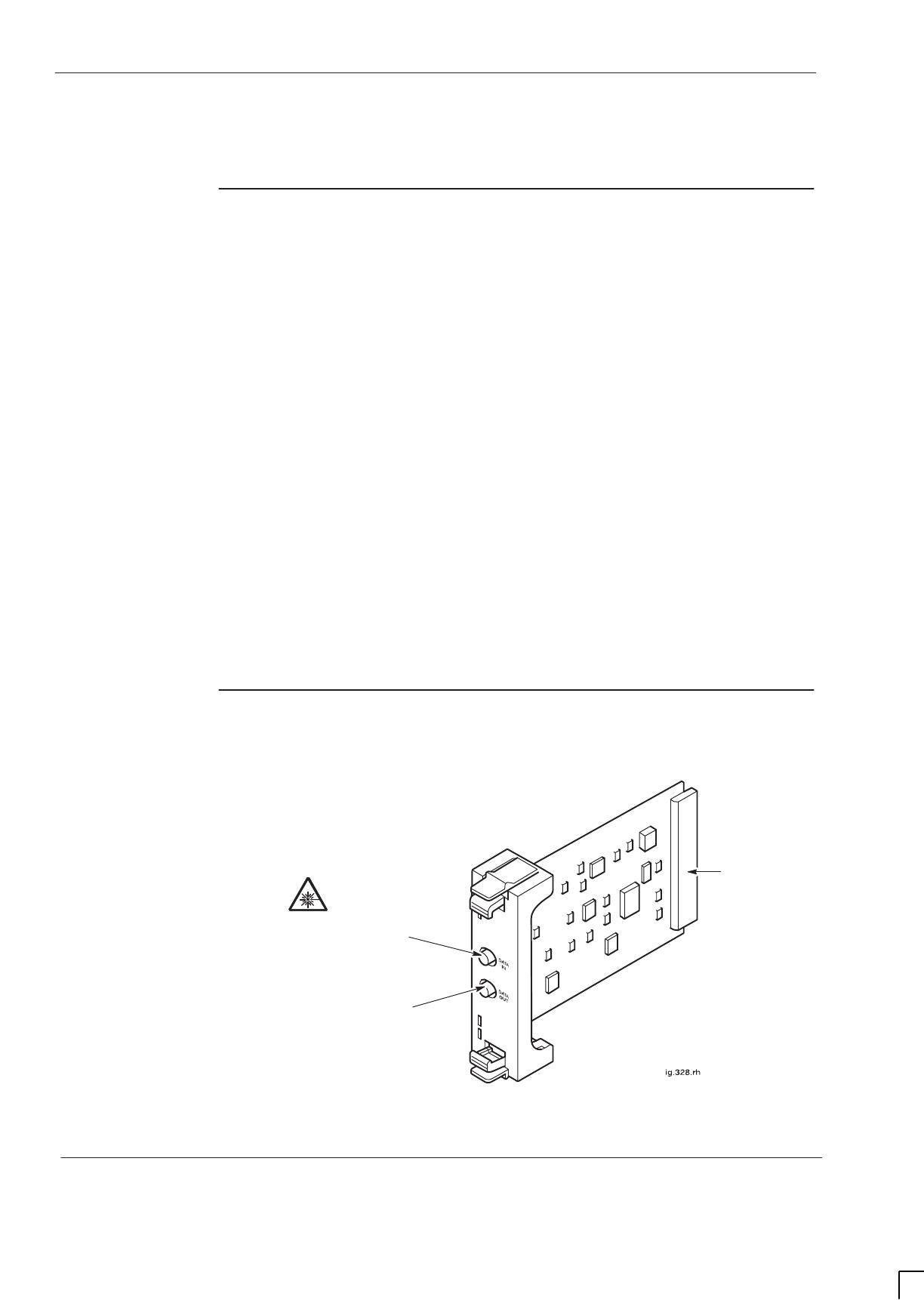
GSM-205-323
FMUX module
31st Oct 01
Tech. 6–22
Technical Description: Horizon
macro
indoor
CONTROLLED INTRODUCTION
68P02902W07-B
FMUX module
Overview of
FMUX module
The fibre optic multiplexer (FMUX) module multiplexes and demultiplexes six,
full duplex, transceiver links to one (TX/Rx) pair of fibre optic cables. This
enables up to six transceivers in a single extension cabinet (either
Horizon
macro
or M-Cell
6
) to be linked to the master cabinet.
The FMUX module has two modes of operation:
SWorking in conjunction with the MCUF to multiplex transceiver links to/from
a third extension cabinet.
SOperating in the extension cabinet to supply the transceivers in that
cabinet.
To enable a total of four cabinets to be joined together as one BTS site, an
FMUX module is required in the master cabinet to connect the third extension
cabinet. A single cabinet site has no need for an FMUX module, because the
MCUF connects with the cabinet CTUs through the backplane.
Two FMUX modules may be fitted in the digital module shelf, one for the master
MCUF, and one for the slave. An extension cabinet only requires one FMUX to
connect to six transceivers within the cabinet, (plus one for redundancy if
required).
Each FMUX fibre optic link is full duplex 16.384 Mbit/s. The FMUX optical link is
capable of driving up to 1 km.
FMUX module
view
Figure 6-8 shows an FMUX module.
BACKPLANE
CONNECTOR
FIBRE OPTIC INPUT FROM
ANOTHER MCUF/FMUX IN
ANOTHER CABINET AT THE SITE
FIBRE OPTIC OUTPUT TO
ANOTHER MCUF/FMUX IN
ANOTHER CABINET AT THE SITE
Figure 6-8 View of the FMUX module
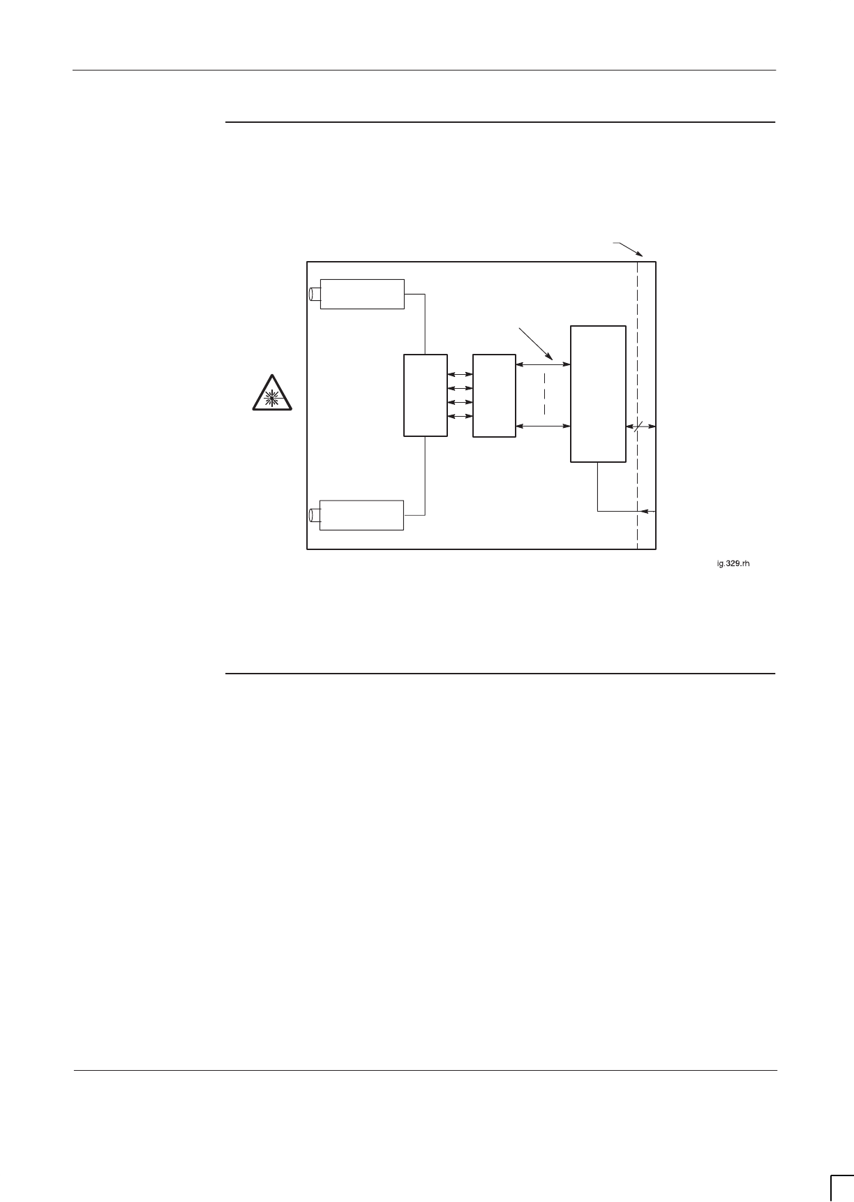
GSM-205-323 FMUX module
31st Oct 01
Technical Description: Horizon
macro
indoor
68P02902W07-B
CONTROLLED INTRODUCTION
Tech. 6–23
FMUX
functional
diagram
Figure 6-9 shows a block diagram of the FMUX module.
FIBRE OPTIC
RECEIVER
FIBRE OPTIC
TRANSMITTER
BACKPLANE CONNECTOR
Rx
DATA
Tx
DATA
SELECT
CONTROL
(FROM
MCUF)
6
MUX/
DEMUX 2:1
SELECT TO MCUF (IF
MASTER
CABINET)
MANCHESTER
ENCODED
Tx/Rx
6
TO FMUX IN
ANOTHER
CABINET
TO FMUX IN
ANOTHER
CABINET
TO CTUs OR
TCUs (IF
EXTENSION
CABINET)
Figure 6-9 Functional diagram of FMUX module
FMUX
functional
explanation
The MCUF transmits and receives a 2.048 Mbit/s data stream link to each
operational transceiver. In the master cabinet this is achieved by the backplane,
without using an FMUX.
If the transceiver is in an extension cabinet, the master cabinet FMUX combines
the data stream with up to five others (see Figure 6-9), and then converts the
electronic signal to fibre optic, for onward transmission to the extension cabinet.
At the extension cabinet, another FMUX converts the fibre optic signal back to
electronic form, for transmission to the transceivers.
The data stream return from the extension cabinet is a reverse of the above.
The multiplexer/demultiplexer can support up to six transceiver links. It uses a
16.384 Mbit/s Manchester encoded serial data link organized as 256 x eight bit
timeslots in a 125 ms frame. Manchester coding is used to detect errors,
indicated at timeslot zero for each transceiver, enabling error correction at the
other FMUX.
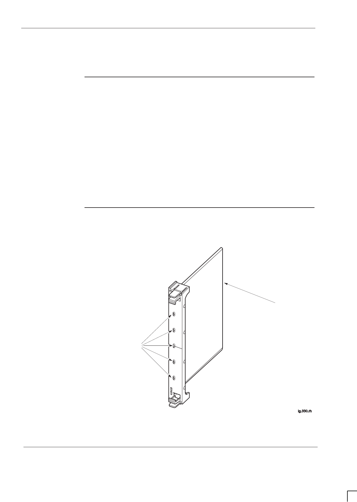
GSM-205-323
Alarm module
31st Oct 01
Tech. 6–24
Technical Description: Horizon
macro
indoor
CONTROLLED INTRODUCTION
68P02902W07-B
Alarm module
Alarm module
overview
The alarm module is located in the digital module shelf, adjacent to the MCUFs.
It provides the cabinet equipment with an external alarm system to report
operational status. The alarm module:
SCollects all cabinet alarms (received from the backplane).
SProvides current sensing for 16 customer inputs, referred to as site
alarms. These inputs are provided by the PIX connectors PIX0 and PIX1.
SControls up to four relay driven outputs linked to customer equipment.
(Changeover contacts 30 V 1 A maximum). These outputs are provided by
the PIX0 connector.
STransmits alarm information to all CTUs in the same cabinet.
Alarm module
view
Figure 6-10 shows an alarm module.
BACKPLANE
CONNECTOR
5 LED PAIRS
Figure 6-10 Alarm module view

GSM-205-323 Alarm module
31st Oct 01
Technical Description: Horizon
macro
indoor
68P02902W07-B
CONTROLLED INTRODUCTION
Tech. 6–25
Alarm module
functionality
The alarm module receives inputs from:
SThe external alarm connector on the interface panel, (from the optional
batery backup system BBS).
SCabinet PSMs (identifying type, manufacturer and slot number).
SEnvironmental control devices.
SCustomer defined alarms.
The alarm board receives these inputs, encodes them, and then passes the
code word to all CTUs in the cabinet via the backplane.
Alarm module
replacement –
effect on alarms
The alarm module can be replaced while the cabinet system is running (hot
replacement). This will temporarily interrupt alarms, with the OMC-R receiving
an additional alarm module out of service alarm, which automatically clears
upon correct insertion of the replacement module.
Alarm collection
from extension
cabinets
Extension cabinet alarms are sent from the extension cabinet alarm module to
the extension cabinet CTUs. The CTUs transmit the alarms to the main cabinet,
by using the normal FMUX connection, for transmission to the MCUF.

GSM-205-323
Alarm module
31st Oct 01
Tech. 6–26
Technical Description: Horizon
macro
indoor
CONTROLLED INTRODUCTION
68P02902W07-B
Alarm module
display
presentation
All alarms LEDs are green or off when equipment is functioning correctly, and
red when equipment is faulty. The LED designations are shown in Table 6-6.
NOTE Only five of the ten front panel LEDs are utilized in the
Horizon
macro
indoor equipment. Others are utilized in the
Horizon
macro
outdoor.
Table 6-6 Alarm module LEDs
LED
location Light
colour
states
Equipment monitored by light
(Green = OK, Red = FAULT)
1 (top) Off/Red Not used in Horizon
macro
indoor.
2 Off/Red Not used in Horizon
macro
indoor.
3 Off/Red Door 1 – main cabinet door open alarm.
4 Off/Red Not used in Horizon
macro
indoor.
5 Off/Red Low voltage disconnect (LVD) alarm (battery
backup option).
6 Green/Red Fan Tray 0 fully operational (4-fan tray).
7 Green/Red Fan Tray 1 fully operational (2-fan tray).
8 Green/Red Fan Tray 2 fully operational (2-fan tray).
9 Off/Red Not used in Horizon
macro
indoor.
10 (bottom) Off/Red Not used in Horizon
macro
indoor.

CHAPTER 2
INSTALLATION OF INDOOR
CABINET
CHAPTER 3
INTEROPERABLITY CHAPTER 4
COMMISSIONING OF
INDOOR CABINET
CHAPTER 5
DECOMMISSIONING OF
CABINET
CHAPTER 1
INTRODUCTION AND SITE
PREPARATION


31st Oct 01
Installation & Configuration: Horizon
macro
indoor
68P02902W08-B
CONTROLLED INTRODUCTION
i
Category 423
Installation & Configuration (Inst.)

GSM-205-423
31st Oct 01
ii
Installation & Configuration: Horizon
macro
indoor
CONTROLLED INTRODUCTION
68P02902W08-B

GSM-205-423
31st Oct 01
Installation & Configuration: Horizon
macro
indoor
68P02902W08-B
CONTROLLED INTRODUCTION
iii
Category 423
Installation & Configuration (Inst.) i. . . . . . . . . . . . . . . . . . . . . . . . . . . . . . . . . .
Chapter 1
Introduction and site preparation i. . . . . . . . . . . . . . . . . . . . . . . . . . . . . . .
Introduction to installation Inst. 1–1. . . . . . . . . . . . . . . . . . . . . . . . . . . . . . . . . . . . . . . . . . . . .
Manual scope Inst. 1–1. . . . . . . . . . . . . . . . . . . . . . . . . . . . . . . . . . . . . . . . . . . . . . . . . .
Software requirements Inst. 1–1. . . . . . . . . . . . . . . . . . . . . . . . . . . . . . . . . . . . . . . . . .
Safety instructions Inst. 1–2. . . . . . . . . . . . . . . . . . . . . . . . . . . . . . . . . . . . . . . . . . . . . .
Horizonmacro indoor tool list Inst. 1–3. . . . . . . . . . . . . . . . . . . . . . . . . . . . . . . . . . . . . . . . . .
Overview of tool list Inst. 1–3. . . . . . . . . . . . . . . . . . . . . . . . . . . . . . . . . . . . . . . . . . . . .
Tool list Inst. 1–3. . . . . . . . . . . . . . . . . . . . . . . . . . . . . . . . . . . . . . . . . . . . . . . . . . . . . . . .
Preparation overview Inst. 1–6. . . . . . . . . . . . . . . . . . . . . . . . . . . . . . . . . . . . . . . . . . . . . . . . .
Overview of site preparation Inst. 1–6. . . . . . . . . . . . . . . . . . . . . . . . . . . . . . . . . . . . . .
Pre-installation procedures Inst. 1–6. . . . . . . . . . . . . . . . . . . . . . . . . . . . . . . . . . . . . . .
Site requirements and considerations Inst. 1–7. . . . . . . . . . . . . . . . . . . . . . . . . . . . . . . . . . .
Overview of requirements Inst. 1–7. . . . . . . . . . . . . . . . . . . . . . . . . . . . . . . . . . . . . . . .
Indoor cabinet dimensions Inst. 1–7. . . . . . . . . . . . . . . . . . . . . . . . . . . . . . . . . . . . . . .
Cabinet weights Inst. 1–8. . . . . . . . . . . . . . . . . . . . . . . . . . . . . . . . . . . . . . . . . . . . . . . .
Torque values Inst. 1–8. . . . . . . . . . . . . . . . . . . . . . . . . . . . . . . . . . . . . . . . . . . . . . . . . .
Power requirements Inst. 1–9. . . . . . . . . . . . . . . . . . . . . . . . . . . . . . . . . . . . . . . . . . . . .
RF output power Inst. 1–10. . . . . . . . . . . . . . . . . . . . . . . . . . . . . . . . . . . . . . . . . . . . . . . .
Environmental requirements Inst. 1–10. . . . . . . . . . . . . . . . . . . . . . . . . . . . . . . . . . . . . .
Structural considerations Inst. 1–11. . . . . . . . . . . . . . . . . . . . . . . . . . . . . . . . . . . . . . . . .
Layout plan Inst. 1–11. . . . . . . . . . . . . . . . . . . . . . . . . . . . . . . . . . . . . . . . . . . . . . . . . . . .
Visiting the site Inst. 1–12. . . . . . . . . . . . . . . . . . . . . . . . . . . . . . . . . . . . . . . . . . . . . . . . . . . . . .
Site visit instructions Inst. 1–12. . . . . . . . . . . . . . . . . . . . . . . . . . . . . . . . . . . . . . . . . . . . .
Before leaving for the site Inst. 1–12. . . . . . . . . . . . . . . . . . . . . . . . . . . . . . . . . . . . . . . .
Arrival at site Inst. 1–12. . . . . . . . . . . . . . . . . . . . . . . . . . . . . . . . . . . . . . . . . . . . . . . . . . .
Leaving the site Inst. 1–12. . . . . . . . . . . . . . . . . . . . . . . . . . . . . . . . . . . . . . . . . . . . . . . . .
Waste material on site Inst. 1–13. . . . . . . . . . . . . . . . . . . . . . . . . . . . . . . . . . . . . . . . . . .
Rural sites Inst. 1–13. . . . . . . . . . . . . . . . . . . . . . . . . . . . . . . . . . . . . . . . . . . . . . . . . . . . .
On site safety Inst. 1–13. . . . . . . . . . . . . . . . . . . . . . . . . . . . . . . . . . . . . . . . . . . . . . . . . .
Preparing the site Inst. 1–14. . . . . . . . . . . . . . . . . . . . . . . . . . . . . . . . . . . . . . . . . . . . . . . . . . . .
Introduction to site preparation Inst. 1–14. . . . . . . . . . . . . . . . . . . . . . . . . . . . . . . . . . .
Base site structure Inst. 1–14. . . . . . . . . . . . . . . . . . . . . . . . . . . . . . . . . . . . . . . . . . . . . .
Site requirements Inst. 1–14. . . . . . . . . . . . . . . . . . . . . . . . . . . . . . . . . . . . . . . . . . . . . . .
Site access Inst. 1–14. . . . . . . . . . . . . . . . . . . . . . . . . . . . . . . . . . . . . . . . . . . . . . . . . . . .
Cabinet installation layout Inst. 1–14. . . . . . . . . . . . . . . . . . . . . . . . . . . . . . . . . . . . . . . .
Chapter 2
Installation of indoor cabinet i. . . . . . . . . . . . . . . . . . . . . . . . . . . . . . . . . . .
Installation overview Inst. 2–1. . . . . . . . . . . . . . . . . . . . . . . . . . . . . . . . . . . . . . . . . . . . . . . . . .
Introduction to installation Inst. 2–1. . . . . . . . . . . . . . . . . . . . . . . . . . . . . . . . . . . . . . . .
Installation sections Inst. 2–2. . . . . . . . . . . . . . . . . . . . . . . . . . . . . . . . . . . . . . . . . . . . .
Cabinet view Inst. 2–3. . . . . . . . . . . . . . . . . . . . . . . . . . . . . . . . . . . . . . . . . . . . . . . . . . .
E1/T1 line testing Inst. 2–3. . . . . . . . . . . . . . . . . . . . . . . . . . . . . . . . . . . . . . . . . . . . . . .

GSM-205-423
31st Oct 01
iv
Installation & Configuration: Horizon
macro
indoor
CONTROLLED INTRODUCTION
68P02902W08-B
Equipment delivery and unpacking Inst. 2–4. . . . . . . . . . . . . . . . . . . . . . . . . . . . . . . . . . . . .
Delivery and packaging overview Inst. 2–4. . . . . . . . . . . . . . . . . . . . . . . . . . . . . . . . .
Packaging crate Inst. 2–4. . . . . . . . . . . . . . . . . . . . . . . . . . . . . . . . . . . . . . . . . . . . . . . .
Equipment module packaging Inst. 2–5. . . . . . . . . . . . . . . . . . . . . . . . . . . . . . . . . . . .
Unpacking the crate, plinth and cabinet Inst. 2–5. . . . . . . . . . . . . . . . . . . . . . . . . . .
Safe disposal of packing material Inst. 2–6. . . . . . . . . . . . . . . . . . . . . . . . . . . . . . . . .
CTU allotted slot retention Inst. 2–6. . . . . . . . . . . . . . . . . . . . . . . . . . . . . . . . . . . . . . .
Installing cabinet plinth Inst. 2–7. . . . . . . . . . . . . . . . . . . . . . . . . . . . . . . . . . . . . . . . . . . . . . .
Overview of foundation and plinth with diagram Inst. 2–7. . . . . . . . . . . . . . . . . . . . .
Recommended bolt length for concrete floor Inst. 2–8. . . . . . . . . . . . . . . . . . . . . . .
Installing the plinth Inst. 2–8. . . . . . . . . . . . . . . . . . . . . . . . . . . . . . . . . . . . . . . . . . . . . .
Fitting cabinet to plinth Inst. 2–9. . . . . . . . . . . . . . . . . . . . . . . . . . . . . . . . . . . . . . . . . . . . . . . .
Methods of plinth use Inst. 2–9. . . . . . . . . . . . . . . . . . . . . . . . . . . . . . . . . . . . . . . . . . . .
Fitting cabinet to plinth Inst. 2–9. . . . . . . . . . . . . . . . . . . . . . . . . . . . . . . . . . . . . . . . . . .
Hood or stacking bracket fit Inst. 2–10. . . . . . . . . . . . . . . . . . . . . . . . . . . . . . . . . . . . . . . . . . .
Introduction to hood and bracket fit Inst. 2–10. . . . . . . . . . . . . . . . . . . . . . . . . . . . . . . .
Diagram of pin location points on cabinet top Inst. 2–10. . . . . . . . . . . . . . . . . . . . . . .
Fitting the optional hood Inst. 2–11. . . . . . . . . . . . . . . . . . . . . . . . . . . . . . . . . . . . . . . . .
Fitting a stacking bracket Inst. 2–12. . . . . . . . . . . . . . . . . . . . . . . . . . . . . . . . . . . . . . . .
Fitting the stacking bracket front cover Inst. 2–13. . . . . . . . . . . . . . . . . . . . . . . . . . . . .
Fitting upper cabinet onto stacking bracket Inst. 2–14. . . . . . . . . . . . . . . . . . . . . . . . . . . . . .
Overview of stacked cabinet fit Inst. 2–14. . . . . . . . . . . . . . . . . . . . . . . . . . . . . . . . . . .
View of eyebolt positions Inst. 2–14. . . . . . . . . . . . . . . . . . . . . . . . . . . . . . . . . . . . . . . . .
Eyebolt positions and safety Inst. 2–15. . . . . . . . . . . . . . . . . . . . . . . . . . . . . . . . . . . . . .
Fitting upper cabinet to stacking bracket Inst. 2–16. . . . . . . . . . . . . . . . . . . . . . . . . . .
Completed stacked cabinet assembly Inst. 2–17. . . . . . . . . . . . . . . . . . . . . . . . . . . . .
Installing CCBs into stacking bracket Inst. 2–18. . . . . . . . . . . . . . . . . . . . . . . . . . . . . . . . . . .
Overview of installing CCBs Inst. 2–18. . . . . . . . . . . . . . . . . . . . . . . . . . . . . . . . . . . . . .
View of DCS1800 CCBs Inst. 2–18. . . . . . . . . . . . . . . . . . . . . . . . . . . . . . . . . . . . . . . . .
Installing CCBs Inst. 2–19. . . . . . . . . . . . . . . . . . . . . . . . . . . . . . . . . . . . . . . . . . . . . . . . .
CCBs installed without front cover Inst. 2–20. . . . . . . . . . . . . . . . . . . . . . . . . . . . . . . . .
Earthing and transient protection Inst. 2–21. . . . . . . . . . . . . . . . . . . . . . . . . . . . . . . . . . . . . . .
Site earthing Inst. 2–21. . . . . . . . . . . . . . . . . . . . . . . . . . . . . . . . . . . . . . . . . . . . . . . . . . .
Transient and lightning protection Inst. 2–21. . . . . . . . . . . . . . . . . . . . . . . . . . . . . . . . .
Connections to RF modules Inst. 2–22. . . . . . . . . . . . . . . . . . . . . . . . . . . . . . . . . . . . . . . . . . .
Overview of RF connections Inst. 2–22. . . . . . . . . . . . . . . . . . . . . . . . . . . . . . . . . . . . . .
Types of RF connector Inst. 2–23. . . . . . . . . . . . . . . . . . . . . . . . . . . . . . . . . . . . . . . . . .
SURF/Tx block interconnecting cables Inst. 2–23. . . . . . . . . . . . . . . . . . . . . . . . . . . . .
Unused SMA connections Inst. 2–23. . . . . . . . . . . . . . . . . . . . . . . . . . . . . . . . . . . . . . . .
Torque of RF connectors Inst. 2–23. . . . . . . . . . . . . . . . . . . . . . . . . . . . . . . . . . . . . . . . .
Tx connection to CCB via feedthrough plates Inst. 2–24. . . . . . . . . . . . . . . . . . . . . . .
RF connection principles Inst. 2–24. . . . . . . . . . . . . . . . . . . . . . . . . . . . . . . . . . . . . . . . .
Rx/Tx single antenna duplexing Inst. 2–24. . . . . . . . . . . . . . . . . . . . . . . . . . . . . . . . . . .

GSM-205-423
31st Oct 01
Installation & Configuration: Horizon
macro
indoor
68P02902W08-B
CONTROLLED INTRODUCTION
v
Suggested RF configurations Inst. 2–25. . . . . . . . . . . . . . . . . . . . . . . . . . . . . . . . . . . . . . . . . .
Overview of configuration diagrams Inst. 2–25. . . . . . . . . . . . . . . . . . . . . . . . . . . . . . .
Configuration for omni 1 Inst. 2–26. . . . . . . . . . . . . . . . . . . . . . . . . . . . . . . . . . . . . . . . .
Configuration for omni 1 or 2 (with and without diversity) Inst. 2–27. . . . . . . . . . . . .
Configuration for omni 3 or 4 Inst. 2–28. . . . . . . . . . . . . . . . . . . . . . . . . . . . . . . . . . . . .
Configuration for omni 3 Inst. 2–28. . . . . . . . . . . . . . . . . . . . . . . . . . . . . . . . . . . . . . . . .
Configuration for omni 4 Inst. 2–29. . . . . . . . . . . . . . . . . . . . . . . . . . . . . . . . . . . . . . . . .
Configuration for omni 5 or 6 Inst. 2–29. . . . . . . . . . . . . . . . . . . . . . . . . . . . . . . . . . . . .
Configuration for sector 1/1 or 2/2 Inst. 2–30. . . . . . . . . . . . . . . . . . . . . . . . . . . . . . . . .
Configuration for sector 1/1 Inst. 2–31. . . . . . . . . . . . . . . . . . . . . . . . . . . . . . . . . . . . . .
Configuration for single cabinet sector 3/3 Inst. 2–31. . . . . . . . . . . . . . . . . . . . . . . . .
Configuration for 2 cabinet sector 3/3 Inst. 2–32. . . . . . . . . . . . . . . . . . . . . . . . . . . . . .
Configuration for 2 cabinet sector 4/4 Inst. 2–32. . . . . . . . . . . . . . . . . . . . . . . . . . . . . .
Configuration for 2 cabinet sector 5/5 or 6/6 Inst. 2–33. . . . . . . . . . . . . . . . . . . . . . . .
Configuration for single cabinet sector 1/1/1, 1/1/2, 1/2/2 or 2/2/2 Inst. 2–34. . . . .
Configuration for 2 cabinet sector 2/2/2 Inst. 2–35. . . . . . . . . . . . . . . . . . . . . . . . . . . .
Configuration for 2 cabinet sector 3/3/3 or 4/4/4 Inst. 2–36. . . . . . . . . . . . . . . . . . . .
Configuration for 2 cabinet sector 4/4/4 Inst. 2–37. . . . . . . . . . . . . . . . . . . . . . . . . . . .
Configuration for 3 cabinet sector 4/4/4 Inst. 2–38. . . . . . . . . . . . . . . . . . . . . . . . . . . .
Configuration for sector 5/5/5 or 6/6/6 Inst. 2–39. . . . . . . . . . . . . . . . . . . . . . . . . . . . .
Configuration for sector 8/8/8 Inst. 2–40. . . . . . . . . . . . . . . . . . . . . . . . . . . . . . . . . . . . .
Configuration for dual band 1/1/1-3/3/3 Inst. 2–41. . . . . . . . . . . . . . . . . . . . . . . . . . . .
Configuration for dual band 3/3/3-1/1/1 Inst. 2–42. . . . . . . . . . . . . . . . . . . . . . . . . . . .
Connecting fibre optic cables Inst. 2–43. . . . . . . . . . . . . . . . . . . . . . . . . . . . . . . . . . . . . . . . . .
Location of fibre optic connections Inst. 2–43. . . . . . . . . . . . . . . . . . . . . . . . . . . . . . . .
Care of fibres Inst. 2–43. . . . . . . . . . . . . . . . . . . . . . . . . . . . . . . . . . . . . . . . . . . . . . . . . . .
Connecting fibre optic cables between cabinets Inst. 2–46. . . . . . . . . . . . . . . . . . . . .
Interface panel cabling Inst. 2–47. . . . . . . . . . . . . . . . . . . . . . . . . . . . . . . . . . . . . . . . . . . . . . . .
Interface panel diagram and pinout overview Inst. 2–47. . . . . . . . . . . . . . . . . . . . . .
Connector pinout tables Inst. 2–48. . . . . . . . . . . . . . . . . . . . . . . . . . . . . . . . . . . . . . . . .
External alarm connector Inst. 2–48. . . . . . . . . . . . . . . . . . . . . . . . . . . . . . . . . . . . . . . .
GPS connector Inst. 2–49. . . . . . . . . . . . . . . . . . . . . . . . . . . . . . . . . . . . . . . . . . . . . . . . .
CCB connector Inst. 2–49. . . . . . . . . . . . . . . . . . . . . . . . . . . . . . . . . . . . . . . . . . . . . . . . .
BIB (BIM) interconnection Inst. 2–50. . . . . . . . . . . . . . . . . . . . . . . . . . . . . . . . . . . . . . . .
T43 (CIM) interconnection Inst. 2–51. . . . . . . . . . . . . . . . . . . . . . . . . . . . . . . . . . . . . . .
PIX conditions input/output Inst. 2–52. . . . . . . . . . . . . . . . . . . . . . . . . . . . . . . . . . . . . . .
ICS connector Inst. 2–53. . . . . . . . . . . . . . . . . . . . . . . . . . . . . . . . . . . . . . . . . . . . . . . . . .
Installing and connecting power and earth cabling Inst. 2–54. . . . . . . . . . . . . . . . . . . . . . .
Overview of power and earth cabling Inst. 2–54. . . . . . . . . . . . . . . . . . . . . . . . . . . . . .
Cable routeing Inst. 2–54. . . . . . . . . . . . . . . . . . . . . . . . . . . . . . . . . . . . . . . . . . . . . . . . . .
Cabinet and ESP earthing points Inst. 2–55. . . . . . . . . . . . . . . . . . . . . . . . . . . . . . . . .
Power supply cable colour coding Inst. 2–55. . . . . . . . . . . . . . . . . . . . . . . . . . . . . . . . .
+ 27 V dc connection procedure Inst. 2–56. . . . . . . . . . . . . . . . . . . . . . . . . . . . . . . . . .
– 48/60 V dc connection procedure Inst. 2–57. . . . . . . . . . . . . . . . . . . . . . . . . . . . . . .
Cabinet ac install Inst. 2–58. . . . . . . . . . . . . . . . . . . . . . . . . . . . . . . . . . . . . . . . . . . . . . .
AC input connection Inst. 2–58. . . . . . . . . . . . . . . . . . . . . . . . . . . . . . . . . . . . . . . . . . . . .
Connecting input power Inst. 2–59. . . . . . . . . . . . . . . . . . . . . . . . . . . . . . . . . . . . . . . . . . . . . . .
Pre-connection checks Inst. 2–59. . . . . . . . . . . . . . . . . . . . . . . . . . . . . . . . . . . . . . . . . .
Connecting dc power Inst. 2–59. . . . . . . . . . . . . . . . . . . . . . . . . . . . . . . . . . . . . . . . . . . .
Connecting ac power Inst. 2–60. . . . . . . . . . . . . . . . . . . . . . . . . . . . . . . . . . . . . . . . . . . .

GSM-205-423
31st Oct 01
vi
Installation & Configuration: Horizon
macro
indoor
CONTROLLED INTRODUCTION
68P02902W08-B
Installing a hold-up battery module Inst. 2–61. . . . . . . . . . . . . . . . . . . . . . . . . . . . . . . . . . . . .
Introduction to hold-up module installation Inst. 2–61. . . . . . . . . . . . . . . . . . . . . . . . .
Installing a hold-up battery module Inst. 2–61. . . . . . . . . . . . . . . . . . . . . . . . . . . . . . . .
Hold-up battery module view Inst. 2–62. . . . . . . . . . . . . . . . . . . . . . . . . . . . . . . . . . . . .
Chapter 3
Interoperability between different Motorola BTSs i. . . . . . . . . . . . . . . .
Introduction to interoperability Inst. 3–1. . . . . . . . . . . . . . . . . . . . . . . . . . . . . . . . . . . . . . . . .
Mixed product sites Inst. 3–1. . . . . . . . . . . . . . . . . . . . . . . . . . . . . . . . . . . . . . . . . . . . .
Architectural constraints Inst. 3–1. . . . . . . . . . . . . . . . . . . . . . . . . . . . . . . . . . . . . . . . .
BTS architectures and interoperability Inst. 3–2. . . . . . . . . . . . . . . . . . . . . . . . . . . . . . . . . .
M-Cell6 and Horizonmacro architectures Inst. 3–2. . . . . . . . . . . . . . . . . . . . . . . . . . .
Example mixed site Inst. 3–3. . . . . . . . . . . . . . . . . . . . . . . . . . . . . . . . . . . . . . . . . . . . .
Technical issues Inst. 3–4. . . . . . . . . . . . . . . . . . . . . . . . . . . . . . . . . . . . . . . . . . . . . . . .
Receive path Inst. 3–4. . . . . . . . . . . . . . . . . . . . . . . . . . . . . . . . . . . . . . . . . . . . . . . . . . .
Transmit path Inst. 3–7. . . . . . . . . . . . . . . . . . . . . . . . . . . . . . . . . . . . . . . . . . . . . . . . . .
M-Cell6 and Horizonmacro hardware equivalents Inst. 3–10. . . . . . . . . . . . . . . . . . .
Further configuration information Inst. 3–10. . . . . . . . . . . . . . . . . . . . . . . . . . . . . . . . . .
Example configurations Inst. 3–11. . . . . . . . . . . . . . . . . . . . . . . . . . . . . . . . . . . . . . . . . .
Special hardware Inst. 3–14. . . . . . . . . . . . . . . . . . . . . . . . . . . . . . . . . . . . . . . . . . . . . . .
Chapter 4
Commissioning of indoor cabinet i. . . . . . . . . . . . . . . . . . . . . . . . . . . . . .
Commissioning overview and test equipment Inst. 4–1. . . . . . . . . . . . . . . . . . . . . . . . . . . .
Overview of commissioning Inst. 4–1. . . . . . . . . . . . . . . . . . . . . . . . . . . . . . . . . . . . . .
PC to MCUF cable pin connections Inst. 4–1. . . . . . . . . . . . . . . . . . . . . . . . . . . . . . .
Test equipment Inst. 4–2. . . . . . . . . . . . . . . . . . . . . . . . . . . . . . . . . . . . . . . . . . . . . . . . .
Pre-power up checks Inst. 4–3. . . . . . . . . . . . . . . . . . . . . . . . . . . . . . . . . . . . . . . . . . . . . . . . .
Overview of pre-power up checks Inst. 4–3. . . . . . . . . . . . . . . . . . . . . . . . . . . . . . . . .
Visual inspection Inst. 4–4. . . . . . . . . . . . . . . . . . . . . . . . . . . . . . . . . . . . . . . . . . . . . . . .
Request for power supply connection Inst. 4–4. . . . . . . . . . . . . . . . . . . . . . . . . . . . . .
Earth continuity check Inst. 4–5. . . . . . . . . . . . . . . . . . . . . . . . . . . . . . . . . . . . . . . . . . .
AC power system insulation check Inst. 4–5. . . . . . . . . . . . . . . . . . . . . . . . . . . . . . . .
Powering up the cabinet Inst. 4–6. . . . . . . . . . . . . . . . . . . . . . . . . . . . . . . . . . . . . . . . . . . . . .
Power up overview Inst. 4–6. . . . . . . . . . . . . . . . . . . . . . . . . . . . . . . . . . . . . . . . . . . . . .
Power up procedure without code load Inst. 4–6. . . . . . . . . . . . . . . . . . . . . . . . . . . .
Power down of cabinet Inst. 4–7. . . . . . . . . . . . . . . . . . . . . . . . . . . . . . . . . . . . . . . . . .
Power up procedure with code load Inst. 4–7. . . . . . . . . . . . . . . . . . . . . . . . . . . . . . .
Installation and configuration Inst. 4–9. . . . . . . . . . . . . . . . . . . . . . . . . . . . . . . . . . . . .
Cabinet and CBM views Inst. 4–10. . . . . . . . . . . . . . . . . . . . . . . . . . . . . . . . . . . . . . . . .
Sample form 1: Request for connection Inst. 4–11. . . . . . . . . . . . . . . . . . . . . . . . . . . . . . . . .
Sample form 2: Completion and inspection form Inst. 4–13. . . . . . . . . . . . . . . . . . . . . . . . .

GSM-205-423
31st Oct 01
Installation & Configuration: Horizon
macro
indoor
68P02902W08-B
CONTROLLED INTRODUCTION
vii
Chapter 5
Decommissioning of cabinet i. . . . . . . . . . . . . . . . . . . . . . . . . . . . . . . . . . .
Decommissioning Horizonmacro indoor Inst. 5–1. . . . . . . . . . . . . . . . . . . . . . . . . . . . . . . . .
Introduction to decommission procedures Inst. 5–1. . . . . . . . . . . . . . . . . . . . . . . . . .
Before cabinet decommission Inst. 5–1. . . . . . . . . . . . . . . . . . . . . . . . . . . . . . . . . . . .
To decommission using checklist Inst. 5–1. . . . . . . . . . . . . . . . . . . . . . . . . . . . . . . . . .
Initial decommission checks Inst. 5–1. . . . . . . . . . . . . . . . . . . . . . . . . . . . . . . . . . . . . .
Powering down the cabinet Inst. 5–2. . . . . . . . . . . . . . . . . . . . . . . . . . . . . . . . . . . . . .
Disconnection of cabinet cables Inst. 5–2. . . . . . . . . . . . . . . . . . . . . . . . . . . . . . . . . .
Eyebolt positions and safety Inst. 5–3. . . . . . . . . . . . . . . . . . . . . . . . . . . . . . . . . . . . . .
Removing upper cabinet in stacked configuration Inst. 5–4. . . . . . . . . . . . . . . . . . .
View of eyebolt positions Inst. 5–5. . . . . . . . . . . . . . . . . . . . . . . . . . . . . . . . . . . . . . . . .
Removing CCBs Inst. 5–6. . . . . . . . . . . . . . . . . . . . . . . . . . . . . . . . . . . . . . . . . . . . . . . .
Removing a stacking bracket Inst. 5–7. . . . . . . . . . . . . . . . . . . . . . . . . . . . . . . . . . . .
Removing floor mounted cabinet Inst. 5–8. . . . . . . . . . . . . . . . . . . . . . . . . . . . . . . . .
Returning equipment to Motorola Inst. 5–8. . . . . . . . . . . . . . . . . . . . . . . . . . . . . . . . .
Horizonmacro indoor decommission checklist Inst. 5–9. . . . . . . . . . . . . . . . . . . . . .

GSM-205-423
31st Oct 01
viii
Installation & Configuration: Horizon
macro
indoor
CONTROLLED INTRODUCTION
68P02902W08-B

31st Oct 01
Installation & Configuration: Horizon
macro
indoor
68P02902W08-B
CONTROLLED INTRODUCTION
i
Chapter 1
Introduction and site preparation

GSM-205-423
31st Oct 01
ii
Installation & Configuration: Horizon
macro
indoor
CONTROLLED INTRODUCTION
68P02902W08-B

GSM-205-423
31st Oct 01
Installation & Configuration: Horizon
macro
indoor
68P02902W08-B
CONTROLLED INTRODUCTION
iii
Chapter 1
Introduction and site preparation i. . . . . . . . . . . . . . . . . . . . . . . . . . . . . . .
Introduction to installation Inst. 1–1. . . . . . . . . . . . . . . . . . . . . . . . . . . . . . . . . . . . . . . . . . . . .
Manual scope Inst. 1–1. . . . . . . . . . . . . . . . . . . . . . . . . . . . . . . . . . . . . . . . . . . . . . . . . .
Software requirements Inst. 1–1. . . . . . . . . . . . . . . . . . . . . . . . . . . . . . . . . . . . . . . . . .
Safety instructions Inst. 1–2. . . . . . . . . . . . . . . . . . . . . . . . . . . . . . . . . . . . . . . . . . . . . .
Horizonmacro indoor tool list Inst. 1–3. . . . . . . . . . . . . . . . . . . . . . . . . . . . . . . . . . . . . . . . . .
Overview of tool list Inst. 1–3. . . . . . . . . . . . . . . . . . . . . . . . . . . . . . . . . . . . . . . . . . . . .
Tool list Inst. 1–3. . . . . . . . . . . . . . . . . . . . . . . . . . . . . . . . . . . . . . . . . . . . . . . . . . . . . . . .
Preparation overview Inst. 1–6. . . . . . . . . . . . . . . . . . . . . . . . . . . . . . . . . . . . . . . . . . . . . . . . .
Overview of site preparation Inst. 1–6. . . . . . . . . . . . . . . . . . . . . . . . . . . . . . . . . . . . . .
Pre-installation procedures Inst. 1–6. . . . . . . . . . . . . . . . . . . . . . . . . . . . . . . . . . . . . . .
Site requirements and considerations Inst. 1–7. . . . . . . . . . . . . . . . . . . . . . . . . . . . . . . . . . .
Overview of requirements Inst. 1–7. . . . . . . . . . . . . . . . . . . . . . . . . . . . . . . . . . . . . . . .
Indoor cabinet dimensions Inst. 1–7. . . . . . . . . . . . . . . . . . . . . . . . . . . . . . . . . . . . . . .
Cabinet weights Inst. 1–8. . . . . . . . . . . . . . . . . . . . . . . . . . . . . . . . . . . . . . . . . . . . . . . .
Torque values Inst. 1–8. . . . . . . . . . . . . . . . . . . . . . . . . . . . . . . . . . . . . . . . . . . . . . . . . .
Power requirements Inst. 1–9. . . . . . . . . . . . . . . . . . . . . . . . . . . . . . . . . . . . . . . . . . . . .
RF output power Inst. 1–10. . . . . . . . . . . . . . . . . . . . . . . . . . . . . . . . . . . . . . . . . . . . . . . .
Environmental requirements Inst. 1–10. . . . . . . . . . . . . . . . . . . . . . . . . . . . . . . . . . . . . .
Structural considerations Inst. 1–11. . . . . . . . . . . . . . . . . . . . . . . . . . . . . . . . . . . . . . . . .
Layout plan Inst. 1–11. . . . . . . . . . . . . . . . . . . . . . . . . . . . . . . . . . . . . . . . . . . . . . . . . . . .
Visiting the site Inst. 1–12. . . . . . . . . . . . . . . . . . . . . . . . . . . . . . . . . . . . . . . . . . . . . . . . . . . . . .
Site visit instructions Inst. 1–12. . . . . . . . . . . . . . . . . . . . . . . . . . . . . . . . . . . . . . . . . . . . .
Before leaving for the site Inst. 1–12. . . . . . . . . . . . . . . . . . . . . . . . . . . . . . . . . . . . . . . .
Arrival at site Inst. 1–12. . . . . . . . . . . . . . . . . . . . . . . . . . . . . . . . . . . . . . . . . . . . . . . . . . .
Leaving the site Inst. 1–12. . . . . . . . . . . . . . . . . . . . . . . . . . . . . . . . . . . . . . . . . . . . . . . . .
Waste material on site Inst. 1–13. . . . . . . . . . . . . . . . . . . . . . . . . . . . . . . . . . . . . . . . . . .
Rural sites Inst. 1–13. . . . . . . . . . . . . . . . . . . . . . . . . . . . . . . . . . . . . . . . . . . . . . . . . . . . .
On site safety Inst. 1–13. . . . . . . . . . . . . . . . . . . . . . . . . . . . . . . . . . . . . . . . . . . . . . . . . .
Preparing the site Inst. 1–14. . . . . . . . . . . . . . . . . . . . . . . . . . . . . . . . . . . . . . . . . . . . . . . . . . . .
Introduction to site preparation Inst. 1–14. . . . . . . . . . . . . . . . . . . . . . . . . . . . . . . . . . .
Base site structure Inst. 1–14. . . . . . . . . . . . . . . . . . . . . . . . . . . . . . . . . . . . . . . . . . . . . .
Site requirements Inst. 1–14. . . . . . . . . . . . . . . . . . . . . . . . . . . . . . . . . . . . . . . . . . . . . . .
Site access Inst. 1–14. . . . . . . . . . . . . . . . . . . . . . . . . . . . . . . . . . . . . . . . . . . . . . . . . . . .
Cabinet installation layout Inst. 1–14. . . . . . . . . . . . . . . . . . . . . . . . . . . . . . . . . . . . . . . .

GSM-205-423
31st Oct 01
iv
Installation & Configuration: Horizon
macro
indoor
CONTROLLED INTRODUCTION
68P02902W08-B

GSM-205-423 Introduction to installation
31st Oct 01
Installation & Configuration: Horizon
macro
indoor
68P02902W08-B
CONTROLLED INTRODUCTION
Inst. 1–1
Introduction to installation
Manual scope
This category (GSM-205-423) covers installation and commissioning for the
cabinet, arranged in the following chapters:
Chapter 1 Introduction and site preparation
General information, safety instructions and information about tools needed to
install the equipment.
Describes the procedures to be followed for initially preparing the site and
installing the necessary ducting and plinths.
Chapter 2 Installation of indoor cabinet
All the procedures necessary to install the cabinet ready for operation and an
overview about the different configurations available.
Chapter 3 Interoperability
Describes interoperability between the Horizon
macro
indoor BTS and earlier
Motorola BTS products.
Chapter 4 Commissioning of indoor cabinet
All procedures necessary to enable the cabinet to be fully operational.
Chapter 5 Decommissioning of indoor cabinet
All procedures necessary to decommission the cabinet.
NOTE For hardware optimization and base site integration, refer
to
Installation and Configuration: BSS Optimization:
(GSM-100-423)
.
Software
requirements
The GSM/EGSM900 and DCS1800 BTSs require software release GSR4 (or
later) in the network.
The GSM850 and PCS1900 BTSs require software release GSR5.1 (or later) in
the network.

GSM-205-423
Introduction to installation
31st Oct 01
Inst. 1–2
Installation & Configuration: Horizon
macro
indoor
CONTROLLED INTRODUCTION
68P02902W08-B
Safety
instructions
WARNING This equipment must only be installed by trained
personnel.
The following safety instructions must be observed when installing the
equipment described in this manual:
SThe installation and configuration procedures described in this manual
must only be carried out by suitably trained personnel.
SInstallation and commissioning must comply with all relevant national and
regional regulations.
SThe equipment must only be installed in a location to which unauthorized
access can be prevented.
SCabinets must be bolted to the plinth base which must be bolted to the
floor.

GSM-205-423 Horizonmacro indoor tool list
31st Oct 01
Installation & Configuration: Horizon
macro
indoor
68P02902W08-B
CONTROLLED INTRODUCTION
Inst. 1–3
Horizon
macro
indoor tool list
Overview of tool
list
This section lists the recommended tools required for installing, commissioning
and maintaining the Horizon
macro
indoor cabinet.
Tool list
Table 1-1 lists the recommended tools for the Horizon
macro
indoor.
Table 1-1 Horizon
macro
indoor tool list
Quantity Description
1 pair Safety goggles
1Hard hat
1Dust mask
1 pair Ear defenders
1Antistatic wrist strap with coiled lead
1Antistatic mat
1Marker pen
1 Torch
1Socket set (A/F/Metric 13 mm or 1/2 sq drive)
1280 mm insulated adjustable spanner
1 each Combination spanners A/F:
1/4, 5/16, 3/8, 7/16, 1/2, 9/16, 5/8, 11/16, 7/8, 3/4, 1.
1 each Combination spanners metric: 8 mm to 25 mm
1Ratchet ring spanner (15 mm x 13 mm)
1Torque spanner (12 mm)
1Torque wrench (1–25 Nm)
1Torxdriver set (T10 to T30) and Security Torxdriver set (T10 to
T30)
16 mm torque spanner (for SMA Tx block connectors)
1Security Allen key set
1Claw hammer
1Pipe cutter
1Junior hacksaw
1300 mm hacksaw
1 pair 150 mm side cutters
1 pair 150 mm heavy–duty side cutters

GSM-205-423
Horizonmacro indoor tool list
31st Oct 01
Inst. 1–4
Installation & Configuration: Horizon
macro
indoor
CONTROLLED INTRODUCTION
68P02902W08-B
Quantity Description
1 pair Flush cut wire cutters
1 pair Light duty cable cutters
1 pair Cable shears
1Knife with retractable blade
1 pair General purpose pliers
1 pair Snipe nose pliers
1 pair Industrial scissors
1 pair GP serrated jaw pliers
1Set of jeweller’s screwdrivers
1Screwdriver set (including flat and cross-head blades)
1Isolating transformer (suitable for site use)
1Piston drill (suitable for drilling concrete and capable of
accepting an M20 drill bit)
1M20 drill bit
1Drill bit set
16 m 240 V extension cable (twin outlet)
1Soldering iron (dual temperature) with holder
1Coax cable stripper for 2002 (75 ohm coaxial cable)
1Hand crimp tool
1Crimp tool for type 43 connectors
1BNC crimp tool with inserts
1Telephone plug crimp tool
150 mm crimp tool
1Cable tie gun
11.5 m wooden step ladder
1Table vice
1250 mm vice grips
17.5 m tape measure
1300 mm steel rule
1Spirit level (1 m)
1Centre punch
1Pocket scriber
1250 mm half round file
1 pair Straight point tweezers
1Null modem

GSM-205-423 Horizonmacro indoor tool list
31st Oct 01
Installation & Configuration: Horizon
macro
indoor
68P02902W08-B
CONTROLLED INTRODUCTION
Inst. 1–5
Quantity Description
1RS232 mini tester
1M to M gender changer

GSM-205-423
Preparation overview
31st Oct 01
Inst. 1–6
Installation & Configuration: Horizon
macro
indoor
CONTROLLED INTRODUCTION
68P02902W08-B
Preparation overview
Overview of site
preparation
This section contains:
SInformation that should be read for initial planning.
SInformation that should be read for safe completion of procedures.
SPre-installation procedures to be followed to prepare the site before
beginning the installation.
Pre-installation
procedures
Pre-installation for the cabinet comprises the sections listed in Table 1-2.
Table 1-2 Pre-installation sections in this chapter
Section Description
Site requirements and
considerations Details mechanical, electrical and structural
parameters to be taken into account when
selecting a site.
Visiting the site Defines the site operating procedures.
Preparing the site Details general site construction
parameters.

GSM-205-423 Site requirements and considerations
31st Oct 01
Installation & Configuration: Horizon
macro
indoor
68P02902W08-B
CONTROLLED INTRODUCTION
Inst. 1–7
Site requirements and considerations
Overview of
requirements
The base site area, where the equipment is to be installed, must meet :
SStructural requirements including:
– Space for all conditions, including maintenance, expansion and
associated cables.
– Allowance for cabinet height. including allowance for second cabinet
placed on top with stacking bracket.
– Allowanance for weight, including that for potential additions on
expansion.
– Additional space to allow door to be opened beyond 90 degrees.
SEnvironmental and power requirements, as defined in manual
specifications.
Indoor cabinet
dimensions
The dimensions of cabinets are listed in Table 1-3.
Table 1-3 Cabinet dimensions
Cabinet type Height Width Depth
Cabinet (without hood) 750 mm 700 mm 430 mm
Cabinet with optional hood 870 mm 700 mm 430 mm
Cabinet with stacking bracket (to hold CCB) 1025 mm 700 mm 430 mm
Two cabinets, with stacking bracket
between, and optional hood on top 1900 mm 700 mm 430 mm
Two cabinets, with stacking bracket
between, and stacking bracket on top. 2050 mm 700 mm 430 mm
The optional hood allows cables to enter the cabinet from the back and above.
The stacking bracket allows a second cabinet to be stacked on top of the first
cabinet. The stacking bracket can also contain a metal basket, in which CCBs
are fitted (the only Tx unit that cannot fit in the cabinet itself).

GSM-205-423
Site requirements and considerations
31st Oct 01
Inst. 1–8
Installation & Configuration: Horizon
macro
indoor
CONTROLLED INTRODUCTION
68P02902W08-B
Cabinet weights
The weights of the fully populated cabinets are listed in Table 1-4.
CAUTION Consider future expansion. Another cabinet may be added
by stacking on top of the existing cabinet. This, if used
with stacking units on both, each with CCBs, and
associated cables, could result in a total weight of 280 kg.
Ensure floor is capable of supporting this weight.
Table 1-4 Main indoor cabinet weights (with six transceivers)
Cabinet with plinth and
hood Cabinet with plinth, stacking bracket and
CCB
115 kg 130 kg
Torque values
Use the torque values listed in Table 1-5 during installation (see NOTE for M12).
Table 1-5 Torque values for all cabinet screws/bolts and RF connectors
Size of
screw/bolt M4 M6 M8 M10 SMA N-type 7/16
Torque value 2.2 Nm 3.4 Nm 5 Nm 10 Nm 1 Nm 3.4 Nm 25 Nm
NOTE Torque values used with M12 anchor bolts will depend on
the anchor bolt manufacturer. Check manufacturers data
for correct values.
GSM-205-423 Site requirements and considerations
31st Oct 01
Installation & Configuration: Horizon
macro
indoor
68P02902W08-B
CONTROLLED INTRODUCTION
Inst. 1–9
Power
requirements
The power requirements of cabinets depends on the configuration. Indoor
cabinets require either ac or a positive or negative earth dc supply.
Power consumption (dc and ac)
Table 1-6 lists typical and maximum power consumption values
Table 1-6 Power consumption of full cabinet, including digital redundancy
Typical measured consumption Maximum power consumption
1400 watts 1700 watts
NOTE Maximum power consumption figures are theoretical
values derived under extreme conditions and are affected
by variables such as temperature, component tolerances,
transmission power and supply voltage. although these
figures must be considered when planning site power
requirements, typical measured consumption values will
be lower.
Cabinet power supply requirements
WARNING All cabinets and supply cables must be protected by a
fuse or circuit breaker selected in accordance with national
and regional wiring regulations.
Table 1-7 lists the power supply requirements for the different power supply
options.
Table 1-7 Main indoor cabinet power supply requirements
Nominal voltage Voltage supply
range Current supply maximum
+27 V dc (negative earth) +20 to +30 V dc 64 A (at nominal voltage)
–48 V dc (positive earth) –39 to –72 V dc 36 A (at nominal voltage)
120/240 V ac (50 – 60 Hz) 88 to 264 7.5 A (at nominal voltage)
NOTE Voltage transients must be less than 35 V peak amplitude
(never below 0 V). Ripple and noise must be less than
200 mV p-p (30 mV rms) over 10 Hz to 14 MHz. Voltage
application stabilization must be within the specified range
in less than 1 second.
GSM-205-423
Site requirements and considerations
31st Oct 01
Inst. 1–10
Installation & Configuration: Horizon
macro
indoor
CONTROLLED INTRODUCTION
68P02902W08-B
RF output
power
Table 1-8 lists the RF power output of the CTU types.
Table 1-8 CTU RF power output at Tx connector
GSM850 and EGSM900 DCS1800 and PCS1900
60 W (47.8 dBm) +/– 1.0 dB 50 W (47.0 dBm) +/–1.0 dB
Table 1-9 lists the expected power output from the various Tx blocks for both
types of CTU.
Table 1-9 RF power output at cabinet after Tx blocks
Tx block GSM850 EGSM900 DCS1800 PCS1900
TDF 40 W
(46.0 dBm) 32 W
(45.1 dBm)
DCF 20 W
(43.0 dBm) 16 W
(42.1 dBm)
DDF 8.5 W
(39.3 dBm) 7 W
(38.5 dBm)
CCB* n/a 20 W
(43.0 dBm) 16 W
(42.1 dBm) n/a
* For a six-channel configuration with minimum cavity separation of 800 kHz.
NOTE CCBs are not currently available for use with the GSM850
or PCS1900 variants.
Environmental
requirements
Table 1-10 lists the operating environmental limits.
Table 1-10 Environmental limits
Environment Temperature Relative Humidity
Operating –5 _C to + 45 _C. 5% to 100% relative humidity, not to
exceed 0.029 g water / m3 dry air.
Storage –45 _C to +70 _C. 8% to 100% relative humidity, not to
exceed 0.029 g water / m3 dry air.
NOTE This specification is valid up to 3 km altitude,
corresponding to an atmospheric pressure range of 648 to
1048 millibars.
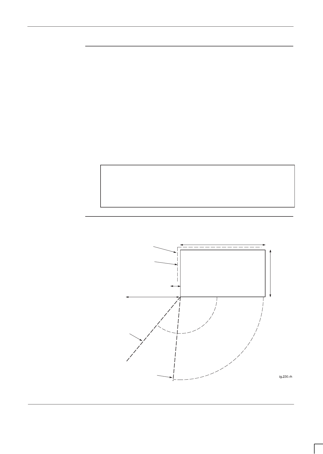
GSM-205-423 Site requirements and considerations
31st Oct 01
Installation & Configuration: Horizon
macro
indoor
68P02902W08-B
CONTROLLED INTRODUCTION
Inst. 1–11
Structural
considerations
Adequate clearance must be provided at the front of the equipment for
operation and maintenance purposes. There must be adequate side clearance
(50 mm) to enable the door to open beyond 90° (see Figure 1-1). The door can
also stop at 95° and 130°, but this is only to protect the door, or give optional
additional operator space.
The cabinet ventilation entry can be solely from the bottom front of the cabinet.
This allows a cabinet to be placed against a wall. However, if the unit is placed
50 mm from back or side obstructions, such as wall or other cabinets, the
ventilation will be improved, and fan noise reduced.
Up to 100 mm rear space may be required for cables if using stacking bracket.
The foundation or structure on which the BTS cabinet is mounted must be of
sufficient strength to support a maximum gross weight of 130 kg for a single
cabinet or 280 kg for two stacked cabinets.
NOTE In seismically active areas, Motorola suggest using a
qualified structural engineer to assess frame mounting
requirements, such as floor construction, mounting
anchors, cell site construction and to provide a suitable
design for top frame support if a stacked configuration is
required.
Layout plan
Figure 1-1 shows the cabinet installation layout plan.
700 mm door at
first position (95°)
100 mm clearance if using stacking
bracket to allow cable space
700 mm door at
second position (130°)
430 mm
700 mm
INDOOR CABINET
50 mm minimum side
clearance for door opening
70 mm width
when door at 95°
500 mm width when
door at 130°
Figure 1-1 Indoor cabinet installation layout plan view

GSM-205-423
Visiting the site
31st Oct 01
Inst. 1–12
Installation & Configuration: Horizon
macro
indoor
CONTROLLED INTRODUCTION
68P02902W08-B
Visiting the site
Site visit
instructions
When preparing to do work at a site and upon arrival, follow the instructions
provided in this section.
Before leaving
for the site
Before leaving for the site:
1. Check that team members have adequate test equipment, tools, and
hardware to complete the tasks. Check for any special requirements.
2. Contact the person in charge of the building to advise of the team’s
estimated time of arrival and the expected duration of their stay on the
site. Usually the logistics will have already been arranged, but it is good
practice to check that the information was received.
3. Ensure that the team read the site access details on each visit to a site as
local regulations may change.
Arrival at site
When entering any site:
1. Do not enter the site before contacting the communications site manager.
Obtain the following information from the building contact:
– Local regulations.
– Parking instructions.
– Waste material removal instructions.
– Directions to canteen facilities (if available).
2. Enter the site.
3. Check for building alarms, for example, intruder alarms, that may have
been activated by entry. If fitted, disable the CO2 gas systems, and any
other alarms activated by entry.
4. Read any local instructions provided.
Leaving the site
When leaving a site:
1. Enable the CO2 gas system, if fitted, and any alarms that were disabled.
2. Contact the local site manager to announce the team’s departure.
3. Sign out of the building as necessary

GSM-205-423 Visiting the site
31st Oct 01
Installation & Configuration: Horizon
macro
indoor
68P02902W08-B
CONTROLLED INTRODUCTION
Inst. 1–13
Waste material
on site
Clear waste material from the site on completion of the job, unless otherwise
indicated by the customer.
WARNING Do not burn waste material, as packaging might give off
toxic gasses.
Rural sites
It is the responsibility of the senior member of the team to ensure that all
personnel on site are aware of all applicable national and regional
environmental regulations or codes of practice and, especially with respect to
water authority sites, any relevant health regulations.
Adhere to these points:
SGuard against all risk of fire.
SFasten all gates (remember site visits could be traced back if a complaint
is made).
SLeave no litter.
SDrive carefully on country roads and observe speed restrictions at all
times.
SKeep to the paths/tracks across farm land.
On site safety
All personnel must:
SEnsure that under no circumstances should anyone move cabinets without
assistance. Cabinets must be safely positioned at all times.
SWear supplied safety helmets when antenna or overhead work is in
progress, and when local regulations require them.
SWear supplied safety goggles and dust masks when drilling. This is
particularly important when drilling overhead ironwork.
SWear supplied ear protectors while drilling is in progress.
SWear approved safety footwear when moving heavy equipment.
Stop any work that you are supervising should any person in your team not be
properly protected, or be unaware of safety requirements.
When installing cable ties, even temporarily, cut the excess or tail properly. This
is to prevent sharp edges inflicting injury when not cut flush with the locking
edge.

GSM-205-423
Preparing the site
31st Oct 01
Inst. 1–14
Installation & Configuration: Horizon
macro
indoor
CONTROLLED INTRODUCTION
68P02902W08-B
Preparing the site
Introduction to
site preparation
This section provides a general overview on the preparation of a site, and site
requirements. For specific sites, refer to the site-specific documentation.
Base site
structure
The base site structure should be designed to meet accepted cellular system
specifications. Additionally, the site must meet the environmental and electrical
operating criteria.
Site
requirements
The customer should provide secure access free from unauthorized personnel,
ample protection from fire, and adequate lighting and clearance at the front and
rear of the equipment for operation and maintenance. Additionally, four cable
ducts with sufficient space for communications cables, mains cables, earth
cables, and antenna RF cables should be provided.
Site access
The site access road and equipment receiving area must be constructed of
asphalt, concrete, or other suitable load bearing aggregate capable of
supporting the transportation vehicle and the cabinet.
NOTE Ensure the unloading area is clear of standing water,
fallen leaves, mud, and building debris.
Cabinet
installation
layout
The cabinet installation layout plans are provided in the Site requirements and
considerations section. Figure 1-1 shows the cabinet installation layout plan
with dimensions.

31st Oct 01
Installation & Configuration: Horizon
macro
indoor
68P02902W08-B
CONTROLLED INTRODUCTION
i
Chapter 2
Installation of indoor cabinet

GSM-205-423
31st Oct 01
ii
Installation & Configuration: Horizon
macro
indoor
CONTROLLED INTRODUCTION
68P02902W08-B

GSM-205-423
31st Oct 01
Installation & Configuration: Horizon
macro
indoor
68P02902W08-B
CONTROLLED INTRODUCTION
iii
Chapter 2
Installation of indoor cabinet i. . . . . . . . . . . . . . . . . . . . . . . . . . . . . . . . . . .
Installation overview Inst. 2–1. . . . . . . . . . . . . . . . . . . . . . . . . . . . . . . . . . . . . . . . . . . . . . . . . .
Introduction to installation Inst. 2–1. . . . . . . . . . . . . . . . . . . . . . . . . . . . . . . . . . . . . . . .
Installation sections Inst. 2–2. . . . . . . . . . . . . . . . . . . . . . . . . . . . . . . . . . . . . . . . . . . . .
Cabinet view Inst. 2–3. . . . . . . . . . . . . . . . . . . . . . . . . . . . . . . . . . . . . . . . . . . . . . . . . . .
E1/T1 line testing Inst. 2–3. . . . . . . . . . . . . . . . . . . . . . . . . . . . . . . . . . . . . . . . . . . . . . .
Equipment delivery and unpacking Inst. 2–4. . . . . . . . . . . . . . . . . . . . . . . . . . . . . . . . . . . . .
Delivery and packaging overview Inst. 2–4. . . . . . . . . . . . . . . . . . . . . . . . . . . . . . . . .
Packaging crate Inst. 2–4. . . . . . . . . . . . . . . . . . . . . . . . . . . . . . . . . . . . . . . . . . . . . . . .
Equipment module packaging Inst. 2–5. . . . . . . . . . . . . . . . . . . . . . . . . . . . . . . . . . . .
Unpacking the crate, plinth and cabinet Inst. 2–5. . . . . . . . . . . . . . . . . . . . . . . . . . .
Safe disposal of packing material Inst. 2–6. . . . . . . . . . . . . . . . . . . . . . . . . . . . . . . . .
CTU allotted slot retention Inst. 2–6. . . . . . . . . . . . . . . . . . . . . . . . . . . . . . . . . . . . . . .
Installing cabinet plinth Inst. 2–7. . . . . . . . . . . . . . . . . . . . . . . . . . . . . . . . . . . . . . . . . . . . . . .
Overview of foundation and plinth with diagram Inst. 2–7. . . . . . . . . . . . . . . . . . . . .
Recommended bolt length for concrete floor Inst. 2–8. . . . . . . . . . . . . . . . . . . . . . .
Installing the plinth Inst. 2–8. . . . . . . . . . . . . . . . . . . . . . . . . . . . . . . . . . . . . . . . . . . . . .
Fitting cabinet to plinth Inst. 2–9. . . . . . . . . . . . . . . . . . . . . . . . . . . . . . . . . . . . . . . . . . . . . . . .
Methods of plinth use Inst. 2–9. . . . . . . . . . . . . . . . . . . . . . . . . . . . . . . . . . . . . . . . . . . .
Fitting cabinet to plinth Inst. 2–9. . . . . . . . . . . . . . . . . . . . . . . . . . . . . . . . . . . . . . . . . . .
Hood or stacking bracket fit Inst. 2–10. . . . . . . . . . . . . . . . . . . . . . . . . . . . . . . . . . . . . . . . . . .
Introduction to hood and bracket fit Inst. 2–10. . . . . . . . . . . . . . . . . . . . . . . . . . . . . . . .
Diagram of pin location points on cabinet top Inst. 2–10. . . . . . . . . . . . . . . . . . . . . . .
Fitting the optional hood Inst. 2–11. . . . . . . . . . . . . . . . . . . . . . . . . . . . . . . . . . . . . . . . .
Fitting a stacking bracket Inst. 2–12. . . . . . . . . . . . . . . . . . . . . . . . . . . . . . . . . . . . . . . .
Fitting the stacking bracket front cover Inst. 2–13. . . . . . . . . . . . . . . . . . . . . . . . . . . . .
Fitting upper cabinet onto stacking bracket Inst. 2–14. . . . . . . . . . . . . . . . . . . . . . . . . . . . . .
Overview of stacked cabinet fit Inst. 2–14. . . . . . . . . . . . . . . . . . . . . . . . . . . . . . . . . . .
View of eyebolt positions Inst. 2–14. . . . . . . . . . . . . . . . . . . . . . . . . . . . . . . . . . . . . . . . .
Eyebolt positions and safety Inst. 2–15. . . . . . . . . . . . . . . . . . . . . . . . . . . . . . . . . . . . . .
Fitting upper cabinet to stacking bracket Inst. 2–16. . . . . . . . . . . . . . . . . . . . . . . . . . .
Completed stacked cabinet assembly Inst. 2–17. . . . . . . . . . . . . . . . . . . . . . . . . . . . .
Installing CCBs into stacking bracket Inst. 2–18. . . . . . . . . . . . . . . . . . . . . . . . . . . . . . . . . . .
Overview of installing CCBs Inst. 2–18. . . . . . . . . . . . . . . . . . . . . . . . . . . . . . . . . . . . . .
View of DCS1800 CCBs Inst. 2–18. . . . . . . . . . . . . . . . . . . . . . . . . . . . . . . . . . . . . . . . .
Installing CCBs Inst. 2–19. . . . . . . . . . . . . . . . . . . . . . . . . . . . . . . . . . . . . . . . . . . . . . . . .
CCBs installed without front cover Inst. 2–20. . . . . . . . . . . . . . . . . . . . . . . . . . . . . . . . .
Earthing and transient protection Inst. 2–21. . . . . . . . . . . . . . . . . . . . . . . . . . . . . . . . . . . . . . .
Site earthing Inst. 2–21. . . . . . . . . . . . . . . . . . . . . . . . . . . . . . . . . . . . . . . . . . . . . . . . . . .
Transient and lightning protection Inst. 2–21. . . . . . . . . . . . . . . . . . . . . . . . . . . . . . . . .
Connections to RF modules Inst. 2–22. . . . . . . . . . . . . . . . . . . . . . . . . . . . . . . . . . . . . . . . . . .
Overview of RF connections Inst. 2–22. . . . . . . . . . . . . . . . . . . . . . . . . . . . . . . . . . . . . .
Types of RF connector Inst. 2–23. . . . . . . . . . . . . . . . . . . . . . . . . . . . . . . . . . . . . . . . . .
SURF/Tx block interconnecting cables Inst. 2–23. . . . . . . . . . . . . . . . . . . . . . . . . . . . .
Unused SMA connections Inst. 2–23. . . . . . . . . . . . . . . . . . . . . . . . . . . . . . . . . . . . . . . .
Torque of RF connectors Inst. 2–23. . . . . . . . . . . . . . . . . . . . . . . . . . . . . . . . . . . . . . . . .
Tx connection to CCB via feedthrough plates Inst. 2–24. . . . . . . . . . . . . . . . . . . . . . .
RF connection principles Inst. 2–24. . . . . . . . . . . . . . . . . . . . . . . . . . . . . . . . . . . . . . . . .
Rx/Tx single antenna duplexing Inst. 2–24. . . . . . . . . . . . . . . . . . . . . . . . . . . . . . . . . . .

GSM-205-423
31st Oct 01
iv
Installation & Configuration: Horizon
macro
indoor
CONTROLLED INTRODUCTION
68P02902W08-B
Suggested RF configurations Inst. 2–25. . . . . . . . . . . . . . . . . . . . . . . . . . . . . . . . . . . . . . . . . .
Overview of configuration diagrams Inst. 2–25. . . . . . . . . . . . . . . . . . . . . . . . . . . . . . .
Configuration for omni 1 Inst. 2–26. . . . . . . . . . . . . . . . . . . . . . . . . . . . . . . . . . . . . . . . .
Configuration for omni 1 or 2 (with and without diversity) Inst. 2–27. . . . . . . . . . . . .
Configuration for omni 3 or 4 Inst. 2–28. . . . . . . . . . . . . . . . . . . . . . . . . . . . . . . . . . . . .
Configuration for omni 3 Inst. 2–28. . . . . . . . . . . . . . . . . . . . . . . . . . . . . . . . . . . . . . . . .
Configuration for omni 4 Inst. 2–29. . . . . . . . . . . . . . . . . . . . . . . . . . . . . . . . . . . . . . . . .
Configuration for omni 5 or 6 Inst. 2–29. . . . . . . . . . . . . . . . . . . . . . . . . . . . . . . . . . . . .
Configuration for sector 1/1 or 2/2 Inst. 2–30. . . . . . . . . . . . . . . . . . . . . . . . . . . . . . . . .
Configuration for sector 1/1 Inst. 2–31. . . . . . . . . . . . . . . . . . . . . . . . . . . . . . . . . . . . . .
Configuration for single cabinet sector 3/3 Inst. 2–31. . . . . . . . . . . . . . . . . . . . . . . . .
Configuration for 2 cabinet sector 3/3 Inst. 2–32. . . . . . . . . . . . . . . . . . . . . . . . . . . . . .
Configuration for 2 cabinet sector 4/4 Inst. 2–32. . . . . . . . . . . . . . . . . . . . . . . . . . . . . .
Configuration for 2 cabinet sector 5/5 or 6/6 Inst. 2–33. . . . . . . . . . . . . . . . . . . . . . . .
Configuration for single cabinet sector 1/1/1, 1/1/2, 1/2/2 or 2/2/2 Inst. 2–34. . . . .
Configuration for 2 cabinet sector 2/2/2 Inst. 2–35. . . . . . . . . . . . . . . . . . . . . . . . . . . .
Configuration for 2 cabinet sector 3/3/3 or 4/4/4 Inst. 2–36. . . . . . . . . . . . . . . . . . . .
Configuration for 2 cabinet sector 4/4/4 Inst. 2–37. . . . . . . . . . . . . . . . . . . . . . . . . . . .
Configuration for 3 cabinet sector 4/4/4 Inst. 2–38. . . . . . . . . . . . . . . . . . . . . . . . . . . .
Configuration for sector 5/5/5 or 6/6/6 Inst. 2–39. . . . . . . . . . . . . . . . . . . . . . . . . . . . .
Configuration for sector 8/8/8 Inst. 2–40. . . . . . . . . . . . . . . . . . . . . . . . . . . . . . . . . . . . .
Configuration for dual band 1/1/1-3/3/3 Inst. 2–41. . . . . . . . . . . . . . . . . . . . . . . . . . . .
Configuration for dual band 3/3/3-1/1/1 Inst. 2–42. . . . . . . . . . . . . . . . . . . . . . . . . . . .
Connecting fibre optic cables Inst. 2–43. . . . . . . . . . . . . . . . . . . . . . . . . . . . . . . . . . . . . . . . . .
Location of fibre optic connections Inst. 2–43. . . . . . . . . . . . . . . . . . . . . . . . . . . . . . . .
Care of fibres Inst. 2–43. . . . . . . . . . . . . . . . . . . . . . . . . . . . . . . . . . . . . . . . . . . . . . . . . . .
Connecting fibre optic cables between cabinets Inst. 2–46. . . . . . . . . . . . . . . . . . . . .
Interface panel cabling Inst. 2–47. . . . . . . . . . . . . . . . . . . . . . . . . . . . . . . . . . . . . . . . . . . . . . . .
Interface panel diagram and pinout overview Inst. 2–47. . . . . . . . . . . . . . . . . . . . . .
Connector pinout tables Inst. 2–48. . . . . . . . . . . . . . . . . . . . . . . . . . . . . . . . . . . . . . . . .
External alarm connector Inst. 2–48. . . . . . . . . . . . . . . . . . . . . . . . . . . . . . . . . . . . . . . .
GPS connector Inst. 2–49. . . . . . . . . . . . . . . . . . . . . . . . . . . . . . . . . . . . . . . . . . . . . . . . .
CCB connector Inst. 2–49. . . . . . . . . . . . . . . . . . . . . . . . . . . . . . . . . . . . . . . . . . . . . . . . .
BIB (BIM) interconnection Inst. 2–50. . . . . . . . . . . . . . . . . . . . . . . . . . . . . . . . . . . . . . . .
T43 (CIM) interconnection Inst. 2–51. . . . . . . . . . . . . . . . . . . . . . . . . . . . . . . . . . . . . . .
PIX conditions input/output Inst. 2–52. . . . . . . . . . . . . . . . . . . . . . . . . . . . . . . . . . . . . . .
ICS connector Inst. 2–53. . . . . . . . . . . . . . . . . . . . . . . . . . . . . . . . . . . . . . . . . . . . . . . . . .
Installing and connecting power and earth cabling Inst. 2–54. . . . . . . . . . . . . . . . . . . . . . .
Overview of power and earth cabling Inst. 2–54. . . . . . . . . . . . . . . . . . . . . . . . . . . . . .
Cable routeing Inst. 2–54. . . . . . . . . . . . . . . . . . . . . . . . . . . . . . . . . . . . . . . . . . . . . . . . . .
Cabinet and ESP earthing points Inst. 2–55. . . . . . . . . . . . . . . . . . . . . . . . . . . . . . . . .
Power supply cable colour coding Inst. 2–55. . . . . . . . . . . . . . . . . . . . . . . . . . . . . . . . .
+ 27 V dc connection procedure Inst. 2–56. . . . . . . . . . . . . . . . . . . . . . . . . . . . . . . . . .
– 48/60 V dc connection procedure Inst. 2–57. . . . . . . . . . . . . . . . . . . . . . . . . . . . . . .
Cabinet ac install Inst. 2–58. . . . . . . . . . . . . . . . . . . . . . . . . . . . . . . . . . . . . . . . . . . . . . .
AC input connection Inst. 2–58. . . . . . . . . . . . . . . . . . . . . . . . . . . . . . . . . . . . . . . . . . . . .
Connecting input power Inst. 2–59. . . . . . . . . . . . . . . . . . . . . . . . . . . . . . . . . . . . . . . . . . . . . . .
Pre-connection checks Inst. 2–59. . . . . . . . . . . . . . . . . . . . . . . . . . . . . . . . . . . . . . . . . .
Connecting dc power Inst. 2–59. . . . . . . . . . . . . . . . . . . . . . . . . . . . . . . . . . . . . . . . . . . .
Connecting ac power Inst. 2–60. . . . . . . . . . . . . . . . . . . . . . . . . . . . . . . . . . . . . . . . . . . .

GSM-205-423
31st Oct 01
Installation & Configuration: Horizon
macro
indoor
68P02902W08-B
CONTROLLED INTRODUCTION
v
Installing a hold-up battery module Inst. 2–61. . . . . . . . . . . . . . . . . . . . . . . . . . . . . . . . . . . . .
Introduction to hold-up module installation Inst. 2–61. . . . . . . . . . . . . . . . . . . . . . . . .
Installing a hold-up battery module Inst. 2–61. . . . . . . . . . . . . . . . . . . . . . . . . . . . . . . .
Hold-up battery module view Inst. 2–62. . . . . . . . . . . . . . . . . . . . . . . . . . . . . . . . . . . . .

GSM-205-423
31st Oct 01
vi
Installation & Configuration: Horizon
macro
indoor
CONTROLLED INTRODUCTION
68P02902W08-B

GSM-205-423 Installation overview
31st Oct 01
Installation & Configuration: Horizon
macro
indoor
68P02902W08-B
CONTROLLED INTRODUCTION
Inst. 2–1
Installation overview
Introduction to
installation
This chapter provides the information required to install cabinets and their
internal and external interfaces.
CAUTION Ensure that all site associated equipment is completely
installed before commissioning the cabinet for operation.
NOTE Some site equipment may not be produced by Motorola,
including battery chargers, power supplies, and antennas.
Refer to site-specific documentation and non-Motorola
vendor instructions.
Before starting an installation, ensure the site has been prepared according to
the description summarized in Preparation overview in the Site preparation
chapter, and the site-specific documentation.
WARNING Do NOT stack more than two Horizon
macro
indoor
cabinets.
The floor mounted cabinet must be securely bolted to the
floor before a second cabinet is stacked on top.
In multiple cabinet sites, up to two Horizon
macro
indoor cabinets may be
stacked with another two stacked Horizon
macro
indoor cabinets installed
adjacent, to provide the maximum 24 carrier BTS site.

GSM-205-423
Installation overview
31st Oct 01
Inst. 2–2
Installation & Configuration: Horizon
macro
indoor
CONTROLLED INTRODUCTION
68P02902W08-B
Installation
sections
Installing cabinets comprises the sections shown in Table 2-1.
Table 2-1 Installation sections in this chapter
Section Description
Equipment delivery
and unpacking Information on delivery packaging, and how
to unpack the equipment.
Installing cabinet
plinth Details the procedure for fitting the cabinet
plinth base.
Fitting cabinet to
plinth Provides procedure for attaching cabinet to
prepared plinth.
Hood or stacking
bracket fit Provides procedure for attaching stacking
bracket on top of any cabinet.
Fitting cabinet onto
stacking bracket Provides procedure for attaching second
cabinet to stacking bracket of first cabinet.
Installing CCBs into
stacking bracket Provides procedure for installing CCBs into
stacking bracket of any cabinet.
Earthing and transient
protection Details site earthing procedures and cabinet
internal earths.
Connecting antennas
and cabinet
configurations
Details setting up antenna connections, with
additional configuration information to
illustrate potential equipment connections.
Interface cabling Details cabling to the interface panel.
Installing power and
earth cabling Details of power supply earthing
requirements.
Connecting input
power Details the correct sequence for power
connection.
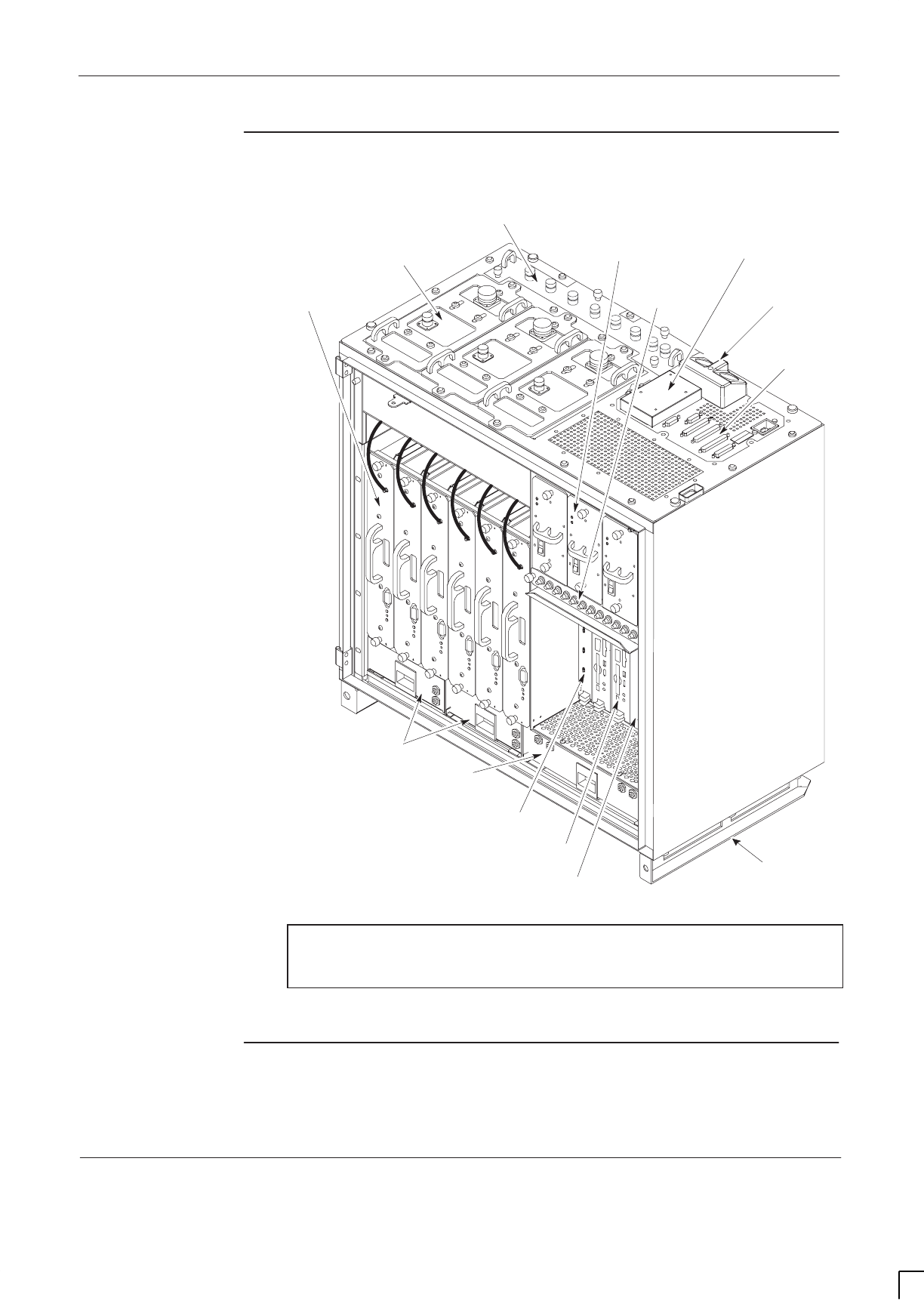
GSM-205-423 Installation overview
31st Oct 01
Installation & Configuration: Horizon
macro
indoor
68P02902W08-B
CONTROLLED INTRODUCTION
Inst. 2–3
Cabinet view
Figure 2-1 shows the main components of a fully equipped cabinet.
CIRCUIT
BREAKER
MODULE (CBM)
RF MODULES POWER SUPPLIES AND
CIRCUIT BREAKER
TEMPERATURE
CONTROL SYSTEM
DIGITAL
MODULES
T43/BIB
MCUF
ALARM MODULE
FMUX/NIU/BPSM
(NOT VISIBLE)
TWO 2-FAN UNITS
ONE 4-FAN UNIT
SIX TRANSCEIVERS
(CTUs)
THREE Tx BLOCKS
(DCFs SHOWN AS EXAMPLE)
ONE SURF (Rx)
THREE PSMs
(see NOTE)
DC POWER IN
INTERFACE
PANEL
CONNECTORS
TOP SECTION OF PLINTH
(SLIDES INTO BASE PLINTH)
NOTE Three PSMs = 2 + 1 redundant (if required). An optional
hold-up battery module may be installed instead of a
redundant PSM.
Figure 2-1 Cabinet with components identified (door and hood removed)
E1/T1 line
testing
If an E1/T1 line has been provided, contact the local MSC and, at the earliest
opportunity, arrange to test the line back to the MSC.
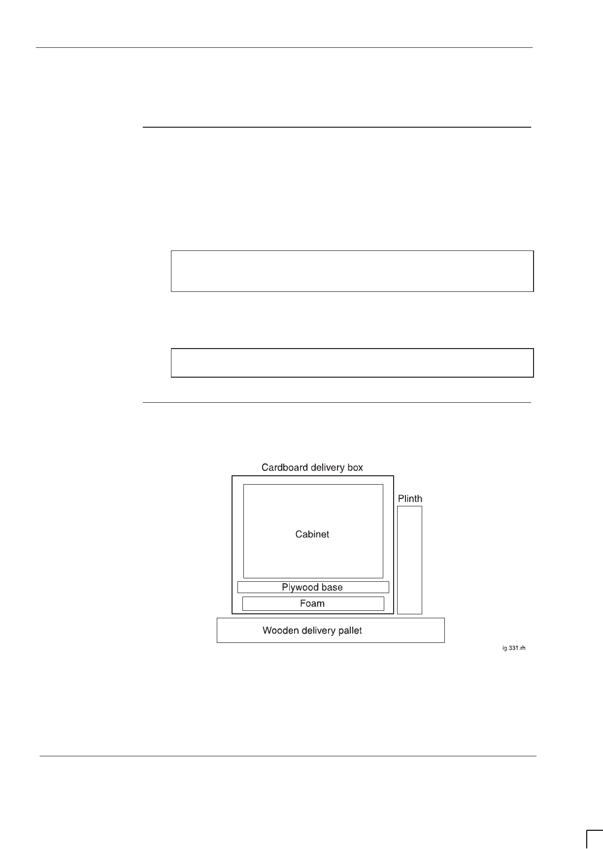
GSM-205-423
Equipment delivery and unpacking
31st Oct 01
Inst. 2–4
Installation & Configuration: Horizon
macro
indoor
CONTROLLED INTRODUCTION
68P02902W08-B
Equipment delivery and unpacking
Delivery and
packaging
overview
Before the cabinet equipment arrives, installation personnel should designate
an area at the site where the equipment can be unloaded. This area should also
be suitable for unpacking the equipment. Consult with the heavy freight or
moving company and the owners of the building (if applicable) to select this
area.
CAUTION The cabinet equipment should be delivered to the site
while still contained in its packaging. This is to protect the
cabinet in transit and from moisture.
The equipment should be carefully delivered to the site by the freight company,
along with the necessary moving dollies and padding. Use the dollies and
padding to move the equipment from the unloading area to the installation point.
NOTE Keep all paperwork attached to packaging, or found inside
cabinet.
Packaging crate
The cabinet equipment is shipped in a crate of a similar construction to that
shown in Figure 2-2.
Figure 2-2 Typical shipping crate detail

GSM-205-423 Equipment delivery and unpacking
31st Oct 01
Installation & Configuration: Horizon
macro
indoor
68P02902W08-B
CONTROLLED INTRODUCTION
Inst. 2–5
Equipment
module
packaging
The equipment modules are supplied already fitted into the cabinet. The only
exception to this is the plinth, supplied in a separate package. The plinth is
attached to the side of the main package to enable preparation work to proceed,
using the plinth, without opening the main cabinet package. This keeps the
cabinet protected during initial preparation.
The optional hood is supplied in a separate package.
Unpacking the
crate, plinth
and cabinet
The following describes the procedure for unpacking the equipment.
NOTE It is recommended that the installer read through the
following procedure before starting to unpack and install
the equipment.
Tools
Use the following tools to dismantle the crate and unpack the cabinet.
SClaw hammer (or similar levering device).
SKnife.
Obtaining plinth base
To obtain the plinth:
1. Cut the plastic banding that secures the crate.
2. Remove separate plinth package, and deliver to site for site preparation if
required separately.
Delivery and dismantling of shipping crate
To deliver and dismantle the shipping crate:
1. Deliver remaining cabinet equipment to site in its original packaging.
NOTE The packing material used by Motorola is non-returnable
and should be disposed of safely.
2. Lift the lid free of the crate.
3. Lift out cardboard protective pieces.
4. Lift the box over the cabinet.

GSM-205-423
Equipment delivery and unpacking
31st Oct 01
Inst. 2–6
Installation & Configuration: Horizon
macro
indoor
CONTROLLED INTRODUCTION
68P02902W08-B
Removing the cabinet from the crate base
WARNING The cabinet can weigh up to 130 kg if fully equipped.
Handle each cabinet with extreme caution, and in
accordance with local health and safety regulations.
To remove the cabinet from the crate base pallet:
CAUTION Care must be taken to avoid damaging the cabinet in any
way, especially by scratching the outer surfaces.
1. Carefully cut open the sealed barrier bag containing the cabinet.
2. Use straps attached to the plywood base holding the cabinet, to lift cabinet
over the delivery pallet and foam packing pieces.
3. Remove the desiccant bag from the cabinet.
4. Inspect the equipment immediately for damage. Report the extent of any
damage to the transport company.
The cabinet is now unpacked.
Safe disposal of
packing
material
The packing material used by Motorola is non-returnable and should be
disposed of safely.
CTU allotted
slot retention
CTUs are supplied already fitted in the cabinet, with Tx cable correctly attached
by Motorola. CTUs must remain in the allotted slots for Motorola calibrations to
be valid.
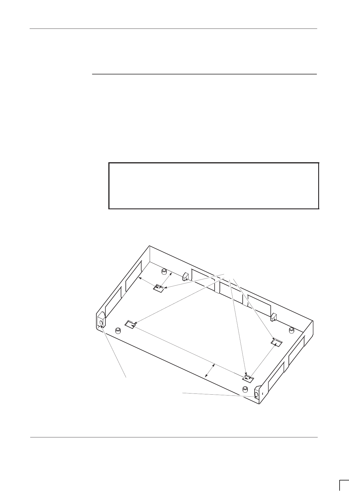
GSM-205-423 Installing cabinet plinth
31st Oct 01
Installation & Configuration: Horizon
macro
indoor
68P02902W08-B
CONTROLLED INTRODUCTION
Inst. 2–7
Installing cabinet plinth
Overview of
foundation and
plinth with
diagram
An indoor cabinet is supplied with a plinth, into which the cabinet structure is
located. This plinth can be used on a smooth, level concrete floor, or other
strong supportive construction. In addition the plinth is used in conjunction with
the stacking bracket in stacked cabinet configurations. The plinth ensures
correct weight distribution, and requires four M12 mounting or anchor bolts to
hold it firmly in position.
WARNING The cabinet must be bolted to the floor using the supplied
plinth. This prevents danger from toppling, if a stacking
bracket is ever added together with a second cabinet on
top. The plinth also reduces fire hazards. NEVER install
the cabinet without the plinth, and ALWAYS bolt the plinth
to the floor. Ensure the selected bolts are suitable.
The plinth is first fitted to the floor, then the cabinet is slid into the plinth and
bolted to the plinth. Figure 2-3 shows the plinth with locations for both floor
attachment and cabinet attachment.
ig.332.rh
LOCATIONS FOR FLOOR
ATTACHMENT
LOCATIONS FOR
CABINET ATTACHMENT
202
mm
99 mm
80 mm
99 mm
503 mm
Figure 2-3 Plinth for cabinet installation

GSM-205-423
Installing cabinet plinth
31st Oct 01
Inst. 2–8
Installation & Configuration: Horizon
macro
indoor
CONTROLLED INTRODUCTION
68P02902W08-B
Recommended
bolt length for
concrete floor
The recommended length of the M12 steel anchor bolts is 105 mm minimum.
This is to ensure adequate strength if stacked cabinets are installed.
Installing the
plinth
If the cabinet is a direct replacement for existing Motorola M-Cell
6
, BTS4 or
BTS6 units, the cabinet can be mounted in place using the existing fixing holes.
Only use existing holes if sufficient space exists for the new configuration (see
Site requirements and considerations).
If the installation is new, the concrete floor must be drilled to accept M12 anchor
bolts. Washers and bushes are supplied, but the M12 steel bolts are supplied
by the customer.
1. Move the cabinet plinth to the selected mounting position. Consider future
as well as present space requirements (see Site requirements and
considerations).
2. Mark the positions of the four mounting holes in the base of the plinth.
These are in the form of four square holes in the middle of the plinth.
3. Move the plinth well away from the mounting position.
WARNING Wear safety glasses and a dust mask when drilling holes.
CAUTION Drilling concrete flooring produces cement dust, which is
harmful to equipment and wiring. Protect the cabinets and
any nearby equipment from dust. Use a tarpaulin, cloth, or
plastic sheeting to cover exposed equipment. Clean up
any accumulated debris from the anchor installation
carefully before exposing the equipment. Use drilling
equipment suitable for cutting steel reinforced concrete.
4. Drill out the four holes to a depth and clearance for an M12 anchor bolt,
using the plinth as a template.
5. Fit the M12 mounting anchors to the holes in the floor.
6. Position the plinth over the mounting anchor holes.
7. Fit the anchor bolts with the supplied bushes and washers, through the
plinth floor, to each anchor.
8. Tension up the anchor bolts and then check for alignment and level using
a spirit level.
9. When satisfied that the plinth is correctly aligned, torque the bolts to the
correct value for M12 bolts (see Site requirements and considerations
in this chapter).
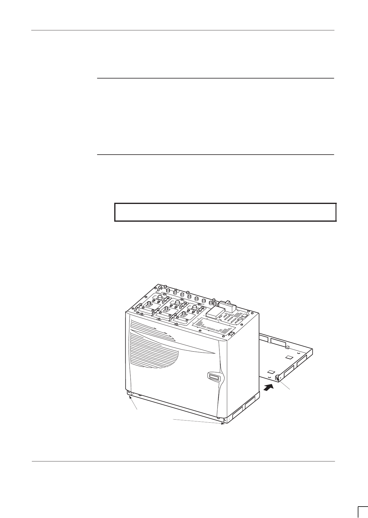
GSM-205-423 Fitting cabinet to plinth
31st Oct 01
Installation & Configuration: Horizon
macro
indoor
68P02902W08-B
CONTROLLED INTRODUCTION
Inst. 2–9
Fitting cabinet to plinth
Methods of
plinth use
There are two methods of using the plinth:
SFor floor mounting, with the plinth previously secured firmly to the floor.
SFor mounting cabinet on a stacking bracket attached to the top of another
cabinet. In this case the plinth is fitted to upper cabinet prior to lifting.
Fitting cabinet
to plinth
To fit the cabinet onto the plinth:
1. Remove the two M10 bolts attached to the front of the plinth.
WARNING Before lifting, ensure that the straps are either side of
each cabinet corner.
2. Tilt and slide the cabinet off the plywood base and move to the plinth,
using the straps provided.
3. Slide cabinet into the plinth grooves, as shown in Figure 2-4.
4. Fit the two M10 bolts and tighten to correct torque (see
Installation &
Configuration: GSM-205-423
Site requirements and considerations).
M10 BOLT
LOCATION
M10 BOLT
POSITIONS FOR
INSERTION
Figure 2-4 Cabinet sliding onto plinth
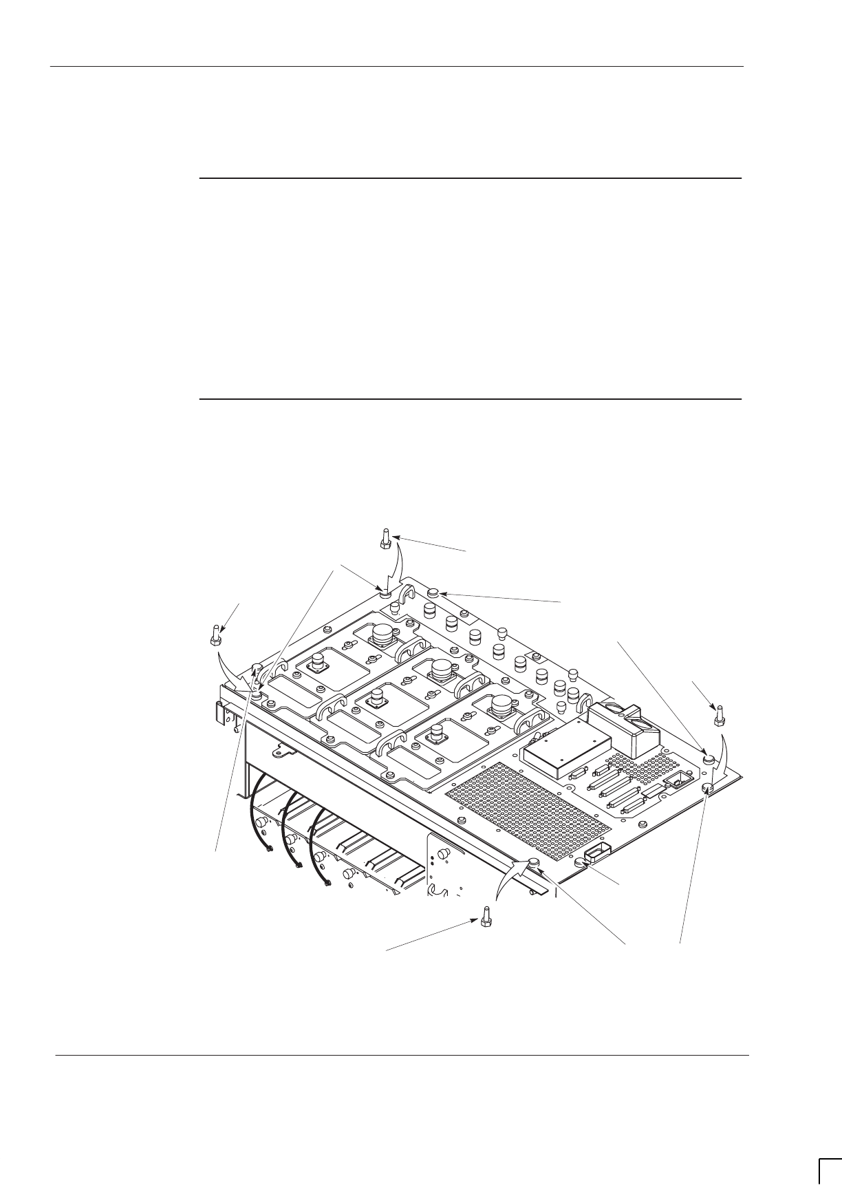
GSM-205-423
Hood or stacking bracket fit
31st Oct 01
Inst. 2–10
Installation & Configuration: Horizon
macro
indoor
CONTROLLED INTRODUCTION
68P02902W08-B
Hood or stacking bracket fit
Introduction to
hood and
bracket fit
If required, the optional hood or stacking bracket are fitted at this stage.
To change from an existing hood to a stacking bracket, the pin locations for the
hood are used by removing the pins before fitting the stacking bracket screws.
Similarly, if replacing a stacking bracket with the optional hood, the appropriate
stacking bracket securing screws are replaced with the hood pins (see
Figure 2-5).
Diagram of pin
location points
on cabinet top
Figure 2-5 shows the eight screw positions used by the stacking bracket,
including the four positions also used for hood pins.
REMOVE SCREWS FOR
STACKING BRACKET ONLY
REMOVE SCREWS FOR
HOOD and STACKING
BRACKET
REMOVE SCREWS FOR HOOD
and STACKING BRACKET
REMOVE
SCREW FOR
STACKING
BRACKET
ONLY
REMOVE
SCREW FOR
STACKING
BRACKET
ONLY
FIT PIN FOR
HOOD
FIT PIN FOR
HOOD
FIT PIN FOR
HOOD
FIT PIN FOR
HOOD
Figure 2-5 Hood pin and stacking bracket screw positions
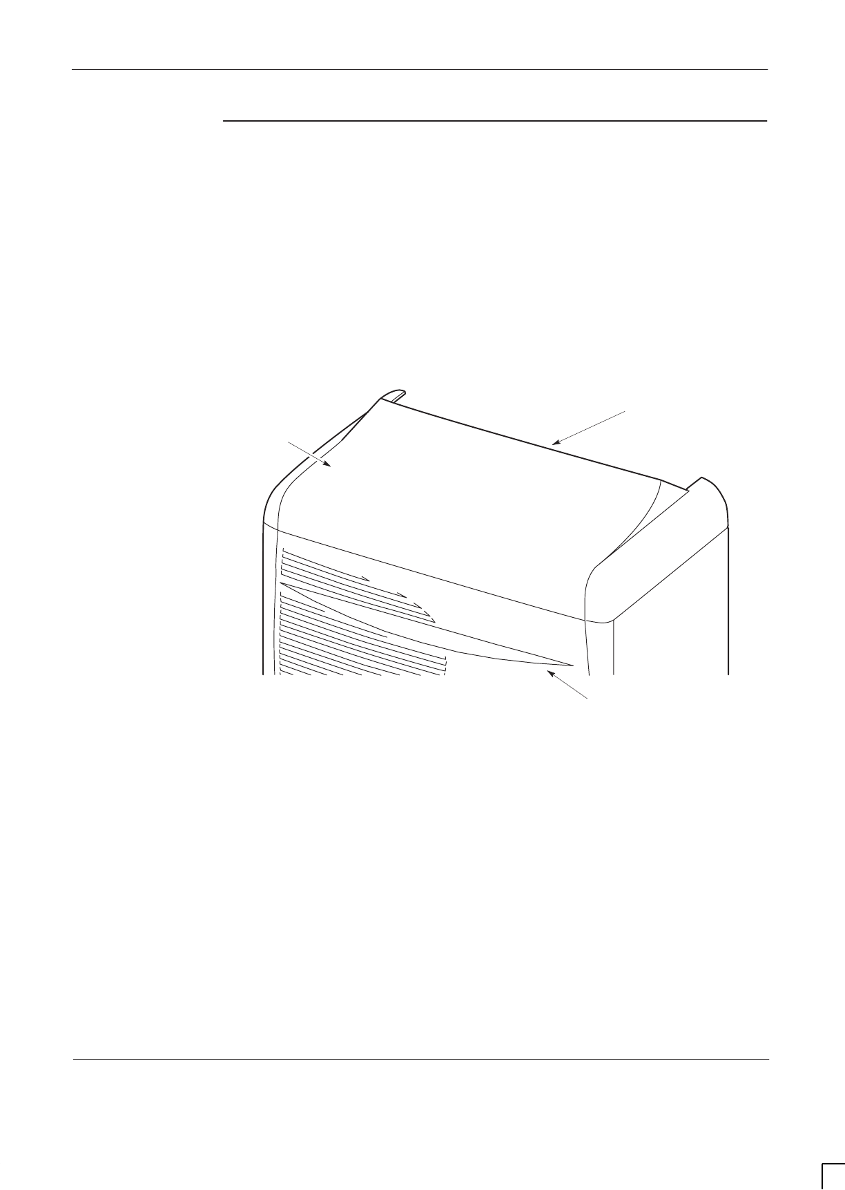
GSM-205-423 Hood or stacking bracket fit
31st Oct 01
Installation & Configuration: Horizon
macro
indoor
68P02902W08-B
CONTROLLED INTRODUCTION
Inst. 2–11
Fitting the
optional hood
The hood is held in place by four pins. To fit the hood:
1. Locate the four top panel M8 screws to be replaced by hood pins, as
shown in Figure 2-7, and remove.
2. Screw the four pins into the cabinet top panel. Tighten to correct torque
(see
Installation & Configuration: GSM-205-423
Site requirements and
considerations).
3. Align the hood with the back pins, then lower the hood onto the pins, and
press firmly into place.
Figure 2-6 shows a top view of the hood as seen when on the cabinet:
ig.333.rh
LIFTING EDGE
HOOD
TOP SECTION OF
CABINET DOOR
Figure 2-6 Hood view when placed on top of cabinet
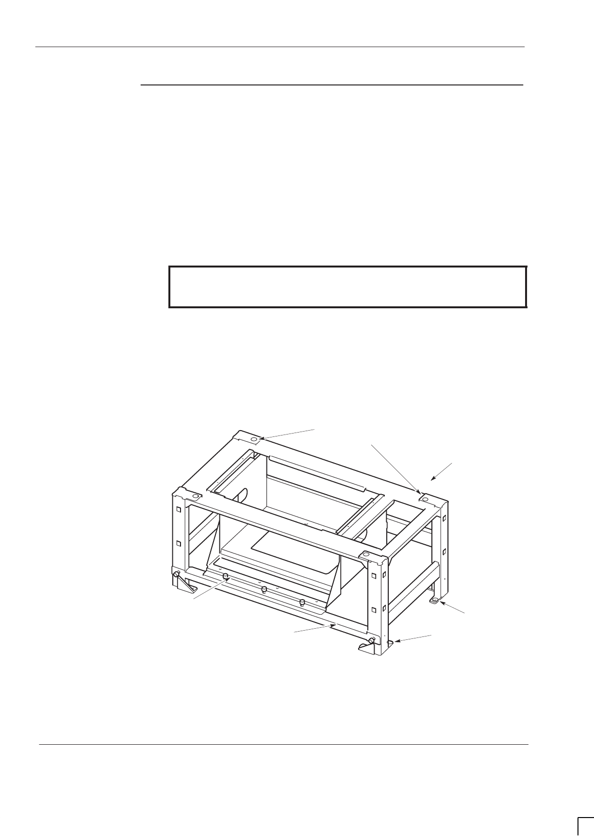
GSM-205-423
Hood or stacking bracket fit
31st Oct 01
Inst. 2–12
Installation & Configuration: Horizon
macro
indoor
CONTROLLED INTRODUCTION
68P02902W08-B
Fitting a
stacking
bracket
To fit a stacking bracket:
1. If an optional hood is fitted:
a. Lift hood by rear lifting edge, until free of the pins.
b. Unscrew and remove the four pins from the cabinet.
Store the pins with the hood.
2. Remove the eight (or four remaining) M8 screws form the cabinet top
panel as shown in Figure 2-7 and retain.
WARNING The stacking bracket can weigh as much as 15 kg (more if
CCBs are contained in the CCB basket). Observe correct
lifting precautions when handling the stacking bracket.
3. Align the stacking bracket onto the cabinet, and fit the eight M8 screws.
Tighten to correct torque (see
Installation & Configuration: GSM-205-423
Site requirements and considerations).
4. Fit the front cover following the procedure detailed in Fitting the stacking
bracket front cover.
Figure 2-7 shows a stacking bracket fitted with optional CCB basket.
ig.268.rh
M8 HOLES (8) FOR
BOTTOM CABINET
ATTACHMENT.
M10 HOLES (4) FOR TOP CABINET
ATTACHMENT (IF REQUIRED)
CCB BASKET
(IF REQUIRED)
DETACHABLE
CCB BASKET BAR
REAR OF
BRACKET
Figure 2-7 View of stacking bracket with optional CCB basket installed
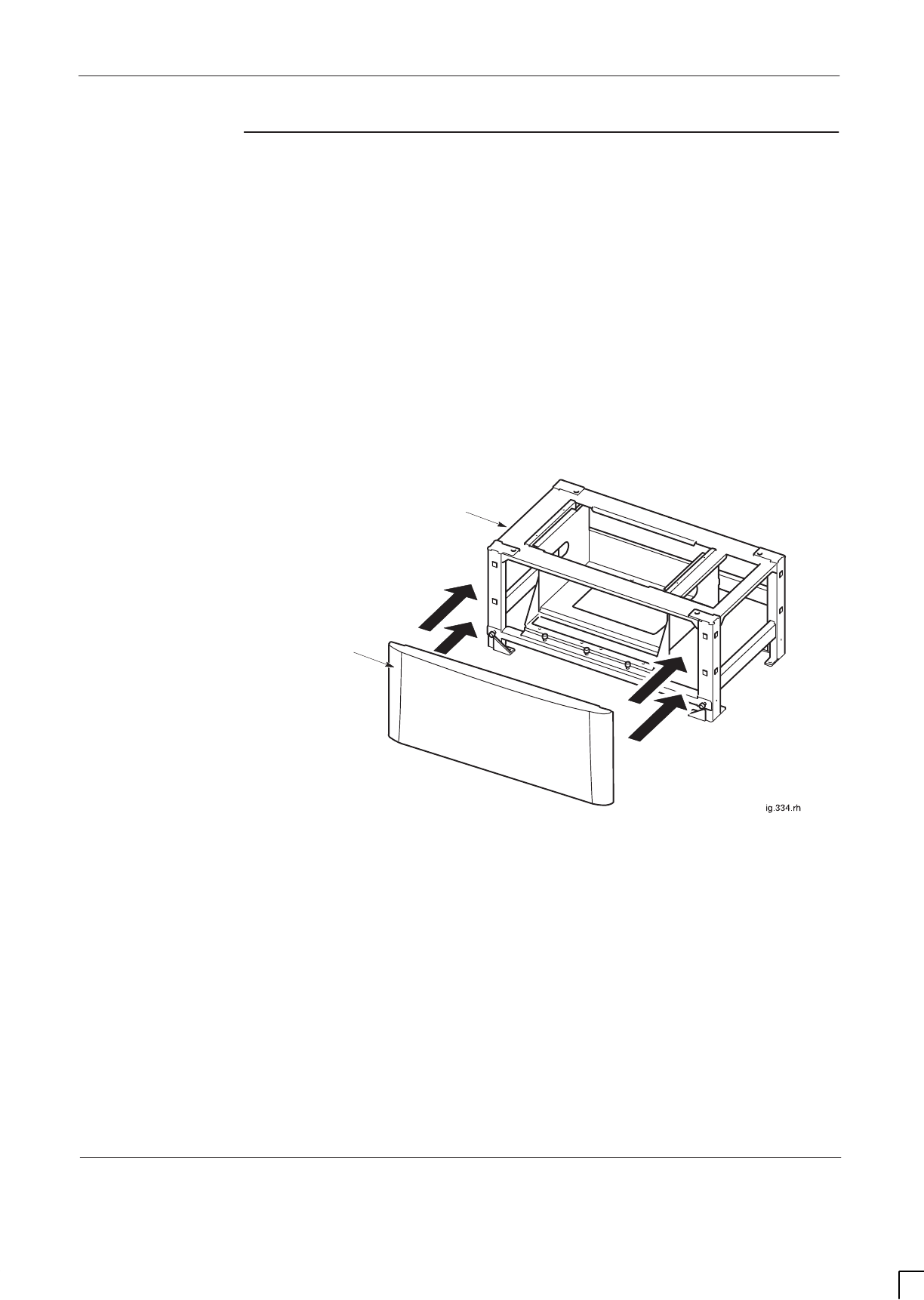
GSM-205-423 Hood or stacking bracket fit
31st Oct 01
Installation & Configuration: Horizon
macro
indoor
68P02902W08-B
CONTROLLED INTRODUCTION
Inst. 2–13
Fitting the
stacking
bracket front
cover
The stacking bracket front cover is attached to the stacking bracket by four
locating clips. The procedure to fit the front cover is as follows:
1. Align the four locating clips on the front cover with the four square holes in
the front of the stacking bracket. Ensure that the cut out slot on each clip
is facing downward.
2. Press the cover against the stacking bracket, so that the cut out slot on
each locating clip engages with the bottom edge of each square hole. It
may be necessary to gently push in and down to ensure the cut out slots
are fully engaged and the cover securely in place.
Figure 2-8 shows the locating points for the stacking bracket front cover.
FRONT
COVER
STACKING
BRACKET
Figure 2-8 Fitting the stacking bracket front cover
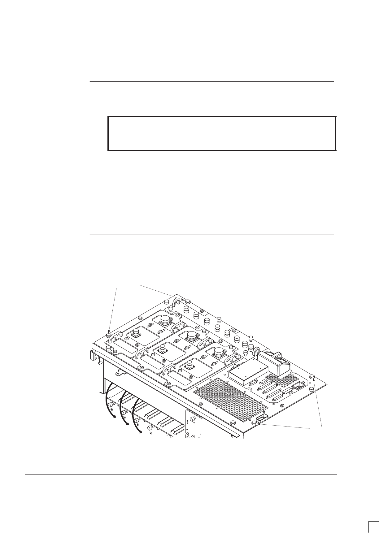
GSM-205-423
Fitting upper cabinet onto stacking bracket
31st Oct 01
Inst. 2–14
Installation & Configuration: Horizon
macro
indoor
CONTROLLED INTRODUCTION
68P02902W08-B
Fitting upper cabinet onto stacking bracket
Overview of
stacked cabinet
fit
WARNING Do NOT stack more than two Horizon
macro
indoor
cabinets.
The floor mounted cabinet must be securely bolted to the
floor before a second cabinet is stacked on top.
In multiple cabinet sites, up to two Horizon
macro
indoor cabinets may be
stacked with another two stacked Horizon
macro
indoor cabinets installed
adjacent, to provide the maximum 24 carrier BTS site.
When a second cabinet is stacked above a floor mounted cabinet, the plinth is
used to secure the cabinet to the stacking bracket mounted on the lower cabinet
top panel. The plinth is connected to the cabinet prior to lifting onto the stacking
bracket.
View of eyebolt
positions
Figure 2-9 shows the positions to which eyebolts can be fitted.
EYEBOLT POSITIONS
EYEBOLT POSITIONS
Figure 2-9 Eyebolt positions

GSM-205-423 Fitting upper cabinet onto stacking bracket
31st Oct 01
Installation & Configuration: Horizon
macro
indoor
68P02902W08-B
CONTROLLED INTRODUCTION
Inst. 2–15
Eyebolt
positions and
safety
There are four eyebolt positions to enable lifting of a second cabinet on top of
the first cabinet stacking bracket. Eyebolts are available from Motorola for this
purpose (part number 0386436N01 – eyebolt, M8).
WARNING The cabinet can weigh as much as 130 kg with stacking
bracket and CCB. Handle cabinets with extreme caution,
and in accordance with any national or regional health and
safety regulations.
Horizon
macro
cabinets are heavy and should not be
installed without the use of lifting equipment unless
sufficient personnel are available to ensure that Health
and Safety regulations are not breached.
Eyebolts used to lift the cabinet must be of the collared
type, manufactured to CE conformity, and must have
sufficient safe working load to lift the cabinet, in
accordance with national or regional health and safety
regulations.
Eyebolts, must be visually checked for damage before
use. If any damage is apparent, DO NOT USE. The
eyebolts must not be overtightened; hand tight is
sufficient.
Motorola recommends the use of slings in conjunction with
hydraulic lifting apparatus for moving and positioning
Horizon
macro
cabinets.
The four screw locations used for hood pins must NOT be
used for eyebolts.
In addition to these points, refer to and comply with any
local regulations that govern the use of lifting equipment.
For the subsequent use of eyebolts, there may be local regulations that govern
the use of lifting equipment and stipulate a test and/or examination regime. If
the eyebolts are to be used, ensure that all such regulations are met.
Eyebolts can be fitted into the four designated cabinet top panel locations,
shown in Figure 2-9, after removal of the screws. These locations are identified
with an eyebolt symbol and the word LIFT. The eyebolt locations are also used
for stacking bracket attachment.

GSM-205-423
Fitting upper cabinet onto stacking bracket
31st Oct 01
Inst. 2–16
Installation & Configuration: Horizon
macro
indoor
CONTROLLED INTRODUCTION
68P02902W08-B
Fitting upper
cabinet to
stacking
bracket
This procedure assumes the upper cabinet has been unpacked (see
Equipment delivery and unpacking).
To install the upper Horizon
macro
indoor cabinet in a stacked configuration:
WARNING Do NOT stack more than two indoor cabinets.
The bottom cabinet must be bolted to the floor using the
supplied plinth. This prevents danger from toppling in
stacked configurations.
1. Ensure the stacking bracket is fitted to the lower cabinet. If not, refer to
Fitting a stacking bracket.
2. Place the plinth in a convenient position, near to unpacked upper cabinet.
3. Fit the cabinet to unsecured plinth as described in Fitting cabinet to
plinth.
WARNING Each cabinet can weigh up to 130 kg if fully equipped.
Handle the cabinets with extreme caution, and in
accordance with local health and safety regulations.
Eyebolts are to be used with lifting equipment. These must
be located in the correct position as shown in Figure 2-9.
The four screw locations used for hood pins must NOT be
used for eyebolts.
Visually check each eyebolt before inserting. If any
damage is apparent, DO NOT USE.
The eyebolts must not be over tightened; hand tight is
sufficient. Do not tighten eyebolts with a t-bar or
spanner. Screw the eyebolt fully into the lifting point so
that no thread is left exposed.
4. Fit the eyebolts to the locations identified with an eyebolt symbol and the
word LIFT. hand tighten the eyebolts and, using suitable lifting equipment,
lift the cabinet onto the stacking bracket and slide to position.
5. Attach four M10 bolts to the cabinet plinth from underneath the top of the
stacking bracket. Tighten to the correct torque (see
Installation &
Configuration: GSM-205-423
Site requirements and considerations).
6. Install the top stacking bracket to hold the CCBs (see Fitting a stacking
bracket) or optional hood (see fitting the optional hood), if required.
CAUTION Incorrect airflow may cause internal cabinet temperatures
to rise above operational limits. Do not obstruct the
honeycomb ventilation panels on the top of the cabinets.
Ensure the stacking brackets are clear of obstruction,
particularly on the right side.
7. Fit a stacking bracket front cover onto each stacking bracket, using the
procedure described in Fitting the stacking bracket front cover.
The finished assembly is shown in Figure 2-10.
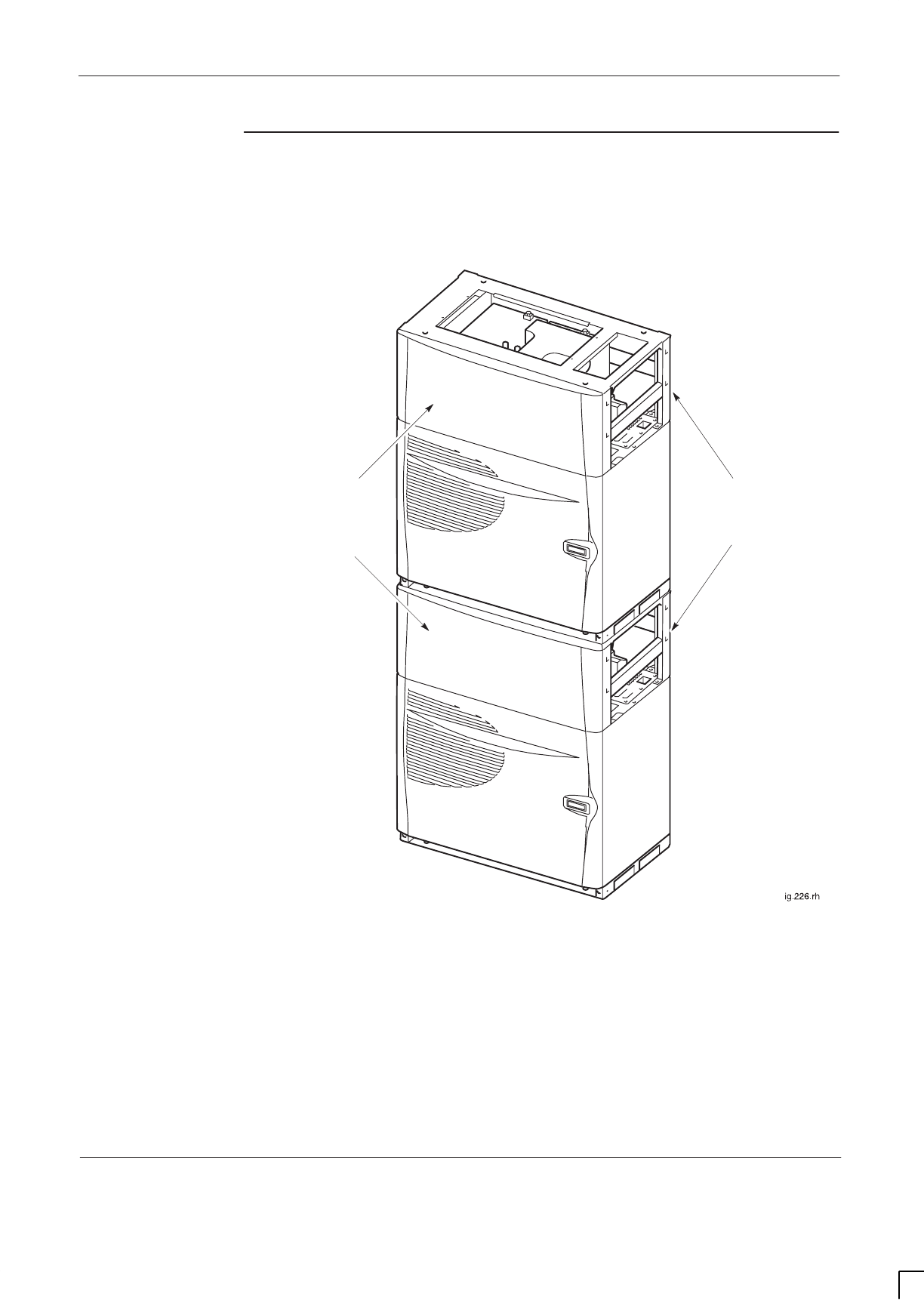
GSM-205-423 Fitting upper cabinet onto stacking bracket
31st Oct 01
Installation & Configuration: Horizon
macro
indoor
68P02902W08-B
CONTROLLED INTRODUCTION
Inst. 2–17
Completed
stacked cabinet
assembly
Figure 2-10 shows the maximum stacked assembly, (two cabinets), with
stacking brackets, covers and CCBs installed.
STACKING
BRACKETS
STACKING
BRACKET
COVERS
Figure 2-10 View of two cabinets stacked with stacking brackets, covers and
CCBs installed
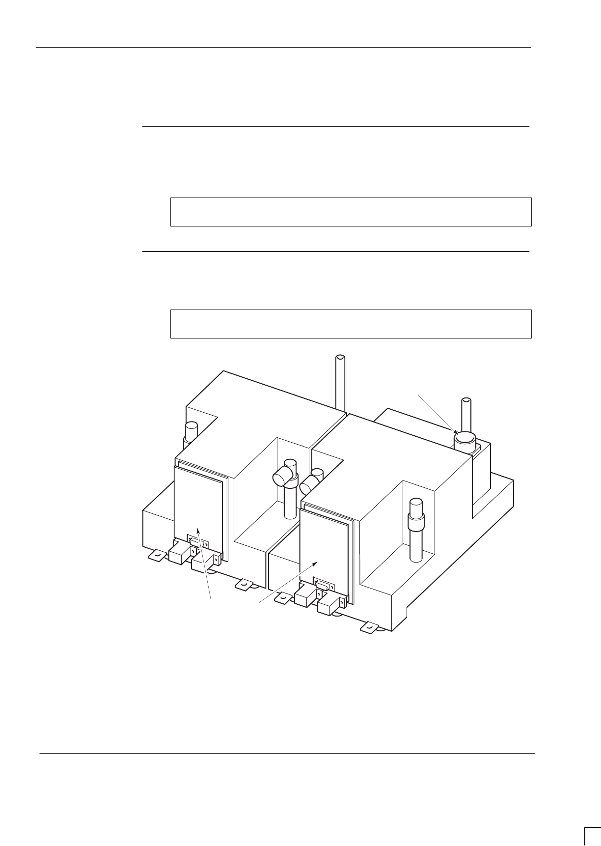
GSM-205-423
Installing CCBs into stacking bracket
31st Oct 01
Inst. 2–18
Installation & Configuration: Horizon
macro
indoor
CONTROLLED INTRODUCTION
68P02902W08-B
Installing CCBs into stacking bracket
Overview of
installing CCBs
A maximum of two CCBs can be fitted into a CCB basket. The CCB basket fits
inside a stacking bracket.
NOTE CCBs are not currently available for use with the GSM850
and PCS1900 BTS variants.
View of
DCS1800 CCBs
Figure 2-11 shows two DCS1800 CCBs, with CCB control boards fitted.
NOTE CCB appearances may vary slightly, depending on type
and manufacturer.
ig.319.rh
CCB CONTROL BOARDS
ANTENNA CONNECTOR
Figure 2-11 Two DCS1800 CCBs with control boards fitted

GSM-205-423 Installing CCBs into stacking bracket
31st Oct 01
Installation & Configuration: Horizon
macro
indoor
68P02902W08-B
CONTROLLED INTRODUCTION
Inst. 2–19
Installing CCBs
Follow these procedures to install CCBs.
Cabinet preparation
1. Ensure the SMA to N-type feedthrough plates are fitted inside the Tx block
basket, with SMA cables installed from CTUs underneath. Ensure the
N-type cables are connected to the feedthrough plates and draped over
the front of the cabinet.
2. Ensure the stacking bracket is fitted to lower cabinet. If not, refer to Fitting
a stacking bracket.
Fitting CCBs into basket
1. Place the CCB basket onto a flat surface.
2. Place the CCBs into the basket and secure with four M6 screws on the
front and two M8 screws at the back. Tighten to the correct torque (see
Installation & Configuration: GSM-205-423
Site requirements and
considerations).
3. Insert each CCB control board, then secure the control board cover with
four M4 screws. Tighten to the correct torque (see
Installation &
Configuration: GSM-205-423
Site requirements and considerations).
4. Connect the phasing lead between the CCB control boards.
Fitting basket to stacking bracket
NOTE Due to space limitations and the need for flexibility,
Motorola recommends the use of Superflex jumper cables
for antenna connections to the CCBs.
1. Slide the basket part way into the stacking bracket, and connect antennas
to the CCBs.
2. Slide the CCB basket fully home.
3. Connect the six N-type to N-type RF cables from the feedthrough plates to
the CCB inputs.
4. Attach the CCB basket bar to the sides of the stacking bracket with the
two captive screws. The bar is then directly underneath the basket captive
screws.
5. Attach the CCB basket bar to the basket with the three captive screws on
the basket.
6. Connect the power cable to each CCB from the single connector (marked
CCB) on the interface panel, shown in Figure 2-36.
7. Fit the front cover onto the stacking bracket, pushing it in so that it drops
into position on the side lugs, as described in Fitting the stacking
bracket front cover.
The fully installed CCBs are illustrated in Figure 2-10 and Figure 2-12.
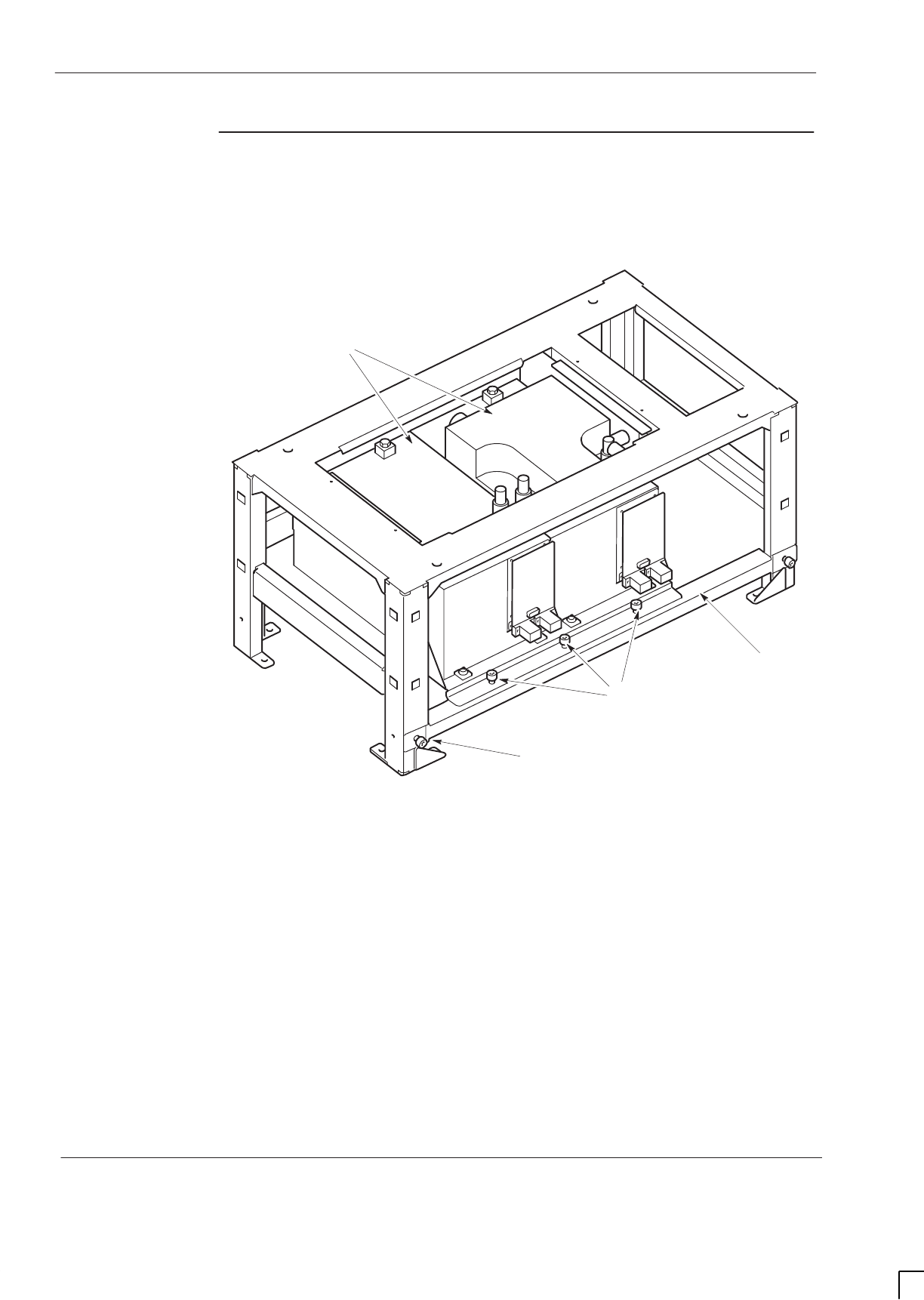
GSM-205-423
Installing CCBs into stacking bracket
31st Oct 01
Inst. 2–20
Installation & Configuration: Horizon
macro
indoor
CONTROLLED INTRODUCTION
68P02902W08-B
CCBs installed
without front
cover
Figure 2-12 shows two EGSM900 CCBs located in stacking bracket (cabinet not
shown).
ig.336.rh
CCB BASKET BAR
CCBs
CAPTIVE SCREW
ON BAR
CAPTIVE SCREWS
ON CCB BASKET
Figure 2-12 CCBs in installed position with CCB basket bar attached

GSM-205-423 Earthing and transient protection
31st Oct 01
Installation & Configuration: Horizon
macro
indoor
68P02902W08-B
CONTROLLED INTRODUCTION
Inst. 2–21
Earthing and transient protection
Site earthing
This manual describes only general procedures for earthing the site. Refer to
the
Grounding guidelines for cellular radio installations 68P81150E62
, for
detailed earthing information.
WARNING Each cabinet must be earthed separately and not daisy
chained together.
SThe cell site equipment must be earthed (in the same common earth point
as its power source).
SProvision should be made for routeing earthing lines into the site and to
the cabinet before beginning the installation of the system cabinets.
SThere is an earthing terminal (stud) located on the interconnect panel on
top of each cabinet.
SRefer to the site-specific documentation for detailed site earthing
information.
Transient and
lightning
protection
All E1/T1 lines connected to Motorola equipment have secondary transient
protection as part of the BIB or T43 board. Ensure the receive and transmit
antenna connections to the building are fed through coaxial electromagnetic
protection (EMP) devices.
CAUTION The end user is responsible for transient protection of the
E1/T1 lines connected to Motorola equipment.
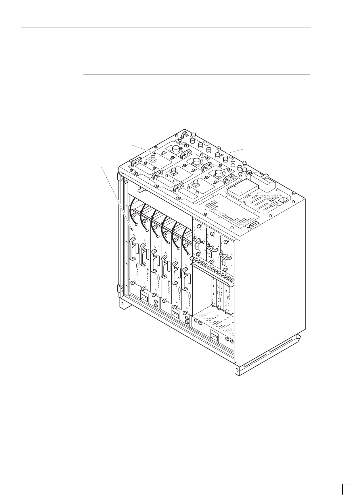
GSM-205-423
Connections to RF modules
31st Oct 01
Inst. 2–22
Installation & Configuration: Horizon
macro
indoor
CONTROLLED INTRODUCTION
68P02902W08-B
Connections to RF modules
Overview of RF
connections
The components shown in Figure 2-13 provide all the RF connections to the
cabinet, and internally within the cabinet. Up to four cabinets can be
interconnected to form a single BTS site.
SIX
TRANSCEIVERS
(CTUs)
SURF
THREE
TRANSMITTER/RECEIVERS
(Tx BLOCKs)
Figure 2-13 Location of RF components

GSM-205-423 Connections to RF modules
31st Oct 01
Installation & Configuration: Horizon
macro
indoor
68P02902W08-B
CONTROLLED INTRODUCTION
Inst. 2–23
Types of RF
connector
Table 2-2 lists the RF module connectors with their destinations.
Table 2-2 RF module connectors and destinations
RF module Type of connector Destination
CTU transceiver SMA Tx Block (underneath)
Tx Block SMA CTU transceiver
N-type SURF
7/16 antenna
SURF N-type Rx N-type of Tx Block
SURF/Tx block
interconnecting
cables
Table 2-3 lists cable types used for SURF/Tx block interconnections.
Table 2-3 SURF/Tx block interconnecting cables
Part number Description Use
3086225N01 34.5 cm coaxial cable terminated at
either end with straight N-type plugs. Tx block to SURF
3086225N02 28 cm coaxial cable terminated at one
end with a straight N-type plug, and at
the other end with a right-angle N-type
plug.
Tx block to Tx
block
3086225N03 2.25 m coaxial cable terminated at
either end with straight N-type plugs. SURF to SURF
3086225N04 2.25 m coaxial cable terminated at one
end with a straight N-type plug, and at
the other end with a right-angle N-type
plug.
Tx block to Tx
block
Unused SMA
connections
Ensure that any unused SMA inputs to DCF, DDF or HCU modules are fitted
with 50 ohm termination loads.
Torque of RF
connectors
CAUTION Care should be taken when tightening SMA connectors to
avoid damage by excess force.
For correct torque of connectors, see
Installation & Configuration: GSM-205-423
Site requirements and considerations.

GSM-205-423
Connections to RF modules
31st Oct 01
Inst. 2–24
Installation & Configuration: Horizon
macro
indoor
CONTROLLED INTRODUCTION
68P02902W08-B
Tx connection
to CCB via
feedthrough
plates
If CCBs are used instead of Tx blocks, the Tx cables are connected through an
N-type to SMA feedthrough plate. This plate converts the normal Tx block SMA
connector underneath to an N-type connector above.
RF connection
principles
The primary receive path is connected to the A branch of the SURF module,
either directly or from the Rx connector on the Tx block in non-diversity
configurations. The diversity receive path is connected to the B path on the
SURF. This is normally duplexed with the transmit signal on a single antenna,
and fed to the SURF from the Rx connector on the Tx block. Within any single
cabinet the lowest numbered sector is normally connected to amplifier 0
connections, and higher numbered sectors to amplifiers 1 and 2 as appropriate.
For example, sector one is connected to SURF connectors 0A and 0B, sector
two to 1A and 1B, and sector three to 2A and 2B. However, if a sector is split
between two cabinets, the split sector antennas must be connected to amplifier
0, (this is the only path with connection to the extension ports). Extension ports
must be connected to the correct branch at the destination cabinet.
The transmit path feeds from the CTUs to the Tx block or feedthrough plate
immediately above. Two signals are combined in most Tx blocks. A third signal
can be combined using a feedthrough plate and the third input of a DDF. The Tx
blocks then duplex the Tx signal with the diversity Rx signal, before feeding to
the antenna.
Rx/Tx single
antenna
duplexing
Duplexers allow a single antenna to be used for both transmit and receive
operations. Duplexers exist within several of the transmit blocks. Normally
duplexed RF signals are used through one antenna, with a second receive
antenna to provide diversity.
CAUTION If a single antenna (non-diversity) is required, the duplex
antenna RF receive cable from the transmit block must be
connected to the RxA path at the SURF. Simply switching
off diversity at the OMC-R without the correct SURF
configuration will cause a loss of reception.

GSM-205-423 Suggested RF configurations
31st Oct 01
Installation & Configuration: Horizon
macro
indoor
68P02902W08-B
CONTROLLED INTRODUCTION
Inst. 2–25
Suggested RF configurations
Overview of
configuration
diagrams
The following series of RF configuration diagrams show suggested ways of
connecting together Horizon
macro
SURF and Tx blocks to meet different
operational requirements. The series of diagrams is by no means exhaustive,
and numerous alternative configurations may be adopted to achieve the same
aim.
Each Horizon
macro
cabinet is represented by a SURF module and three Tx
blocks. Interconnecting cables are identified by a label; N01, 2, 3 or 4. Further
details of each cable type are shown in Table 2-3. Antenna connecting cables,
not supplied as part of the Horizon
macro
equipment, are shown as dotted lines.
With the exception of Figure 2-33 and Figure 2-34, the diagrams are applicable
to GSM850, EGSM900, DCS1800 or PCS1900 single band operation, although
only the 1800 SURF module is illustrated.
NOTE Dual band 900 and 1800 SURFs are available, but 850
and 1900 SURFs are only available as single band.
Figure 2-33 shows one way of achieving dual band operation using two
Horizon
macro
cabinets. A single band 1800 SURF is installed in one cabinet
and a dual band 900 SURF in the other. Figure 2-34 shows another, using one
of each type of dual band SURF.
Diversity is assumed in the majority of RF configuration diagrams shown here,
Figure 2-15 being the exception. Other non diversity configurations can be
derived from this figure by ensuring that the single receive path is always
connected to branch A at the SURF module.
Digital connections
Digital connections between cabinets are not shown in the following diagrams.
Fibre optic cables used to provide digital connections between cabinets are
described in Connecting fibre optic cables.
Depopulated site configurations
The purpose of a depopulated site configuration is to allow customers to provide
a future expansion capability, at the time of installation. The diagram showing
the final target configuration is to be used to connect Tx blocks, SURF and
antennas. Depopulated site configurations are supplied with fully equipped RF
section to achieve the target configuration, with CTUs only fitted to alternate
slots. CTUs are fitted in slots 0, 2 and 4. Unused Tx block SMA connectors must
be fitted with 50 ohm terminating loads.
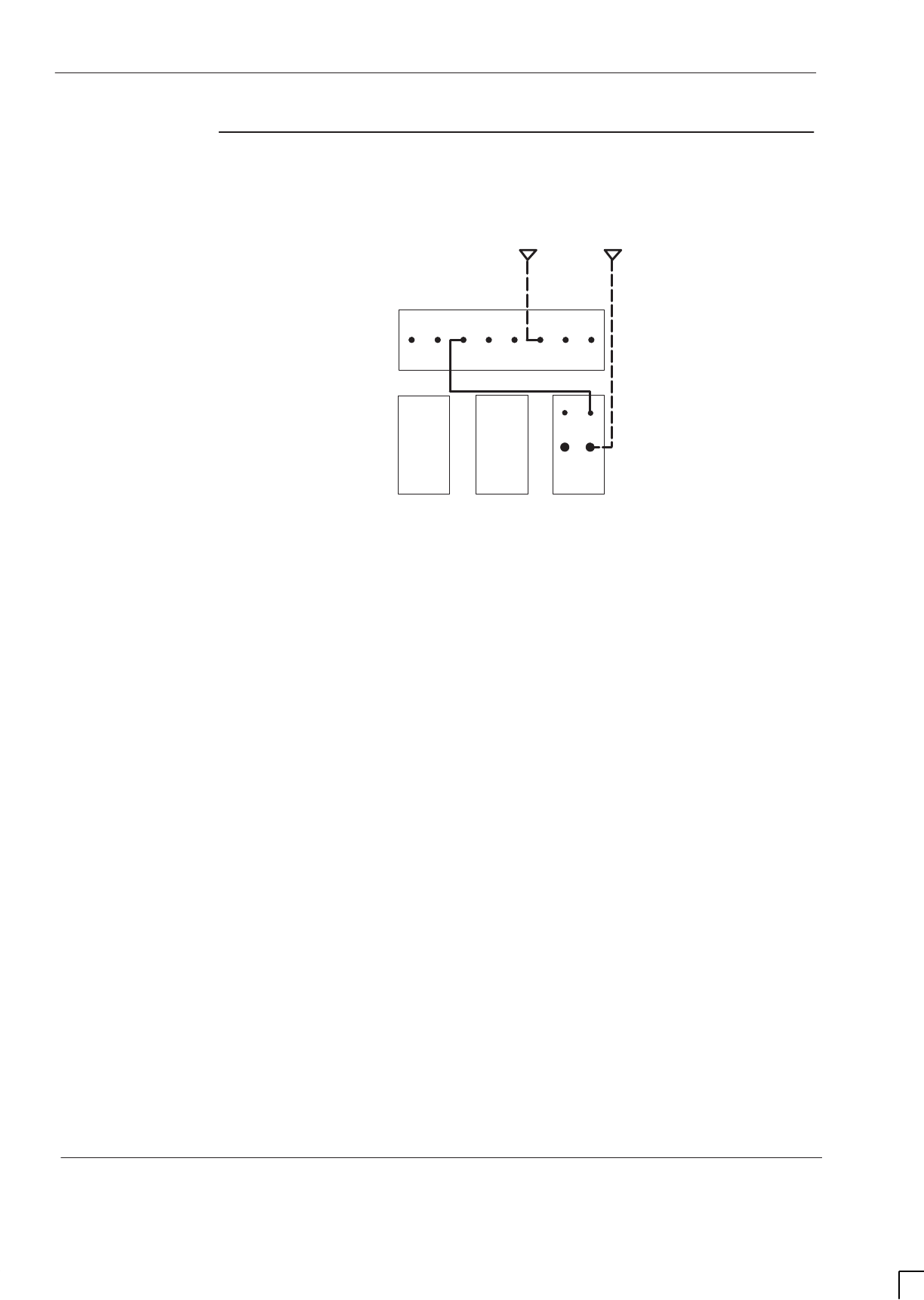
GSM-205-423
Suggested RF configurations
31st Oct 01
Inst. 2–26
Installation & Configuration: Horizon
macro
indoor
CONTROLLED INTRODUCTION
68P02902W08-B
Configuration
for omni 1
Figure 2-14 shows a suggested configuration, using one Horizon
macro
cabinet,
for omni 1 with twin duplexed filter.
B
EXT
RX
RX
RX
RX
RX
RX
EXT
A0A1A2A0B1B2B
20
ANT
RX
TDF
N01
1
RX
BLANK
BLANK
ANT
Figure 2-14 Single cabinet omni 1 with TDF
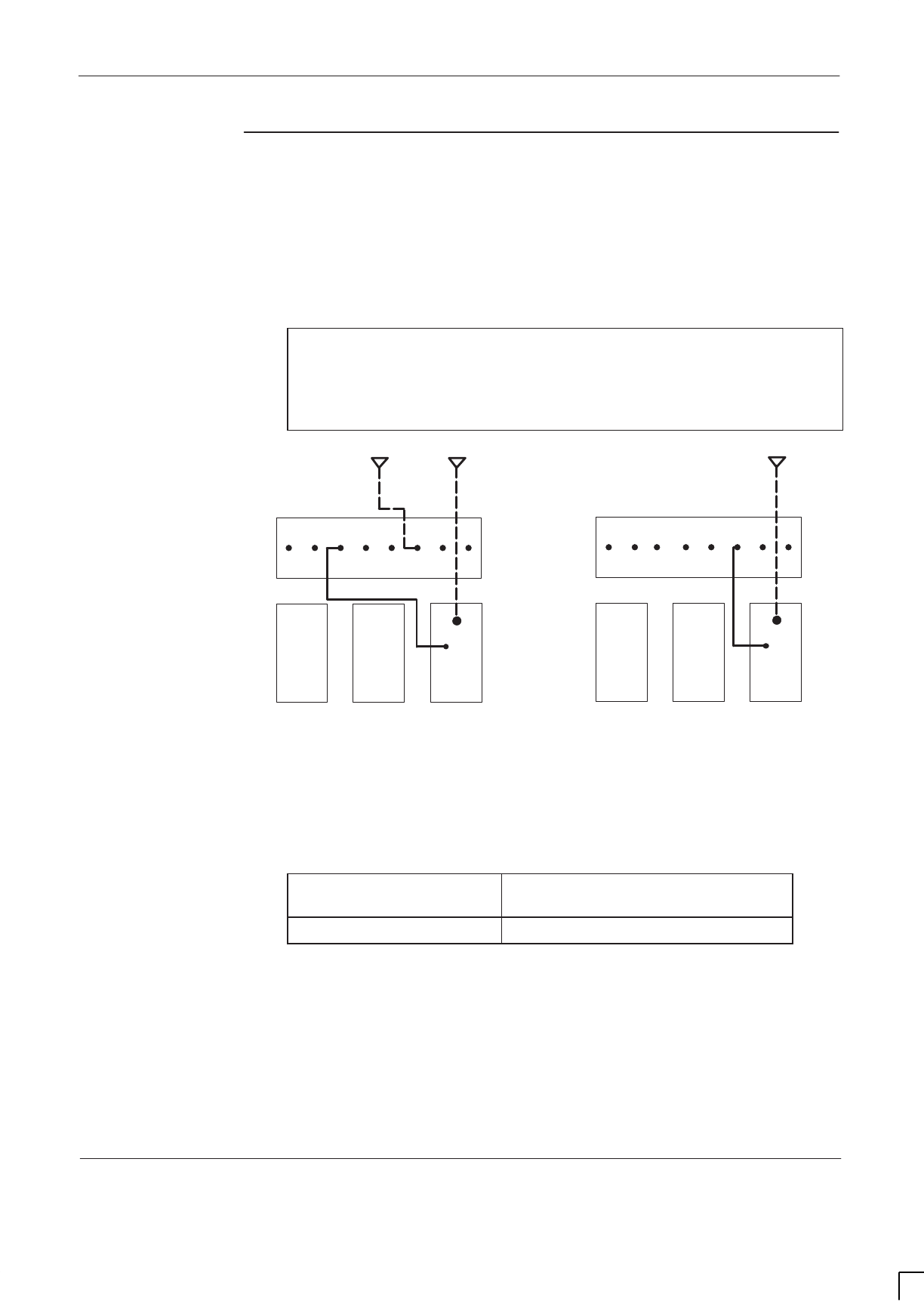
GSM-205-423 Suggested RF configurations
31st Oct 01
Installation & Configuration: Horizon
macro
indoor
68P02902W08-B
CONTROLLED INTRODUCTION
Inst. 2–27
Configuration
for omni 1 or 2
(with and
without
diversity)
Figure 2-15 shows suggested single Horizon
macro
cabinet configurations, with
and without diversity, for omni 1 or omni 2 with duplexed combining bandpass
filter.
NOTE If a single antenna (non-diversity) is required, the duplex
antenna RF receive cable from the transmit block must be
connected to the RxA path at the SURF. Simply switching
off diversity at the OMC-R without the correct SURF
configuration will cause a loss of reception.
B
EXT
RX
RX
RX
RX
RX
RX
EXT
A0A1A2A0B1B2B
2
BLANK
0
ANT
RX
DCF
1
N01
BLANK
WITH DIVERSITY
RX
RX
B
EXT
RX
RX
RX
RX
EXT
A0A1A2A0B1B2B
2
BLANK
0
ANT
RX
DCF
1
N01
BLANK
WITHOUT DIVERSITY
Figure 2-15 Single cabinet omni 1 or 2 with DCF
Unused SMA connectors must be fitted with 50 ohm terminating loads as shown
below.
If configured for... Then 50 ohm load required on
unused SMA input to...
omni 1 DCF 0
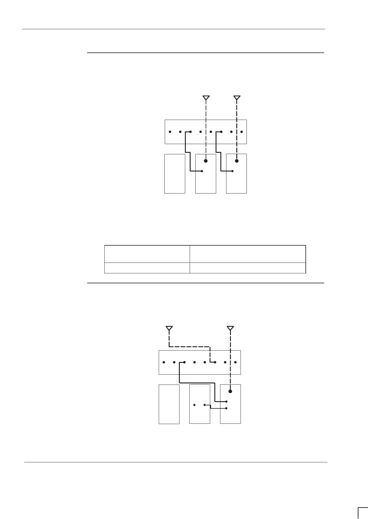
GSM-205-423
Suggested RF configurations
31st Oct 01
Inst. 2–28
Installation & Configuration: Horizon
macro
indoor
CONTROLLED INTRODUCTION
68P02902W08-B
Configuration
for omni 3 or 4
Figure 2-16 shows a suggested configuration, using a single Horizon
macro
cabinet, for omni 3 or omni 4 with duplexed combining bandpass filter.
B
EXT
RX
RX
RX
RX
RX
RX
EXT
A0A1A2A0B1B2B
2
BLANK
0
ANT
RX
DCF
N01
ANT
RX
DCF
1
N01
Figure 2-16 Single cabinet omni 3 or 4 with DCF
Unused SMA connectors must be fitted with 50 ohm terminating loads as shown
below.
If configured for... Then 50 ohm load required on
unused SMA input to...
omni 3 DCF 1
Configuration
for omni 3
Figure 2-17 shows a suggested configuration, using one Horizon
macro
cabinet,
for omni 3 with dual stage duplexed combining filter.
B
EXT
RX
RX
RX
RX
RX
RX
EXT
A0A1A2A0B1B2B
2
BLANK FEED
THRU
0
ANT
RX
DDF
N01
1
TXTX
N02
Figure 2-17 Single cabinet omni 3 with DDF
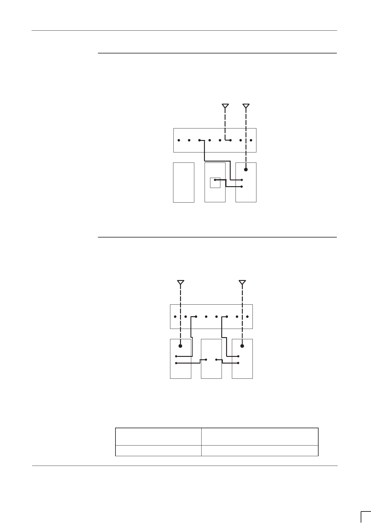
GSM-205-423 Suggested RF configurations
31st Oct 01
Installation & Configuration: Horizon
macro
indoor
68P02902W08-B
CONTROLLED INTRODUCTION
Inst. 2–29
Configuration
for omni 4
Figure 2-18 shows a suggested configuration, using a single Horizon
macro
cabinet, for omni 4 with dual stage duplexed combining filter and hybrid
combining unit.
B
EXT
RX
RX
RX
RX
RX
RX
EXT
A0A1A2A0B1B2B
2
BLANK
0
ANT
RX
DDF
N01
TXTX
N02
1
HCU
TX
Figure 2-18 Single cabinet omni 4 with DDF and HCU
Configuration
for omni 5 or 6
Figure 2-19 shows a suggested configuration, using one Horizon
macro
cabinet,
for omni 5 or 6 with dual stage duplexed combining filter and air combining.
B
EXT
RX
RX
RX
RX
RX
RX
EXT
A0A1A2A0B1B2B
N02
2
ANT
RX
DDF FEED
THRU
0
ANT
RX
DDF
N01
1
TX TXTX
N02
N01
Figure 2-19 Single cabinet omni 5 or 6 with DDF and air combining
Unused SMA connectors must be fitted with 50 ohm terminating loads as shown
below.
If configured for... Then 50 ohm load required on
unused SMA input to...
omni 5 DDF 2
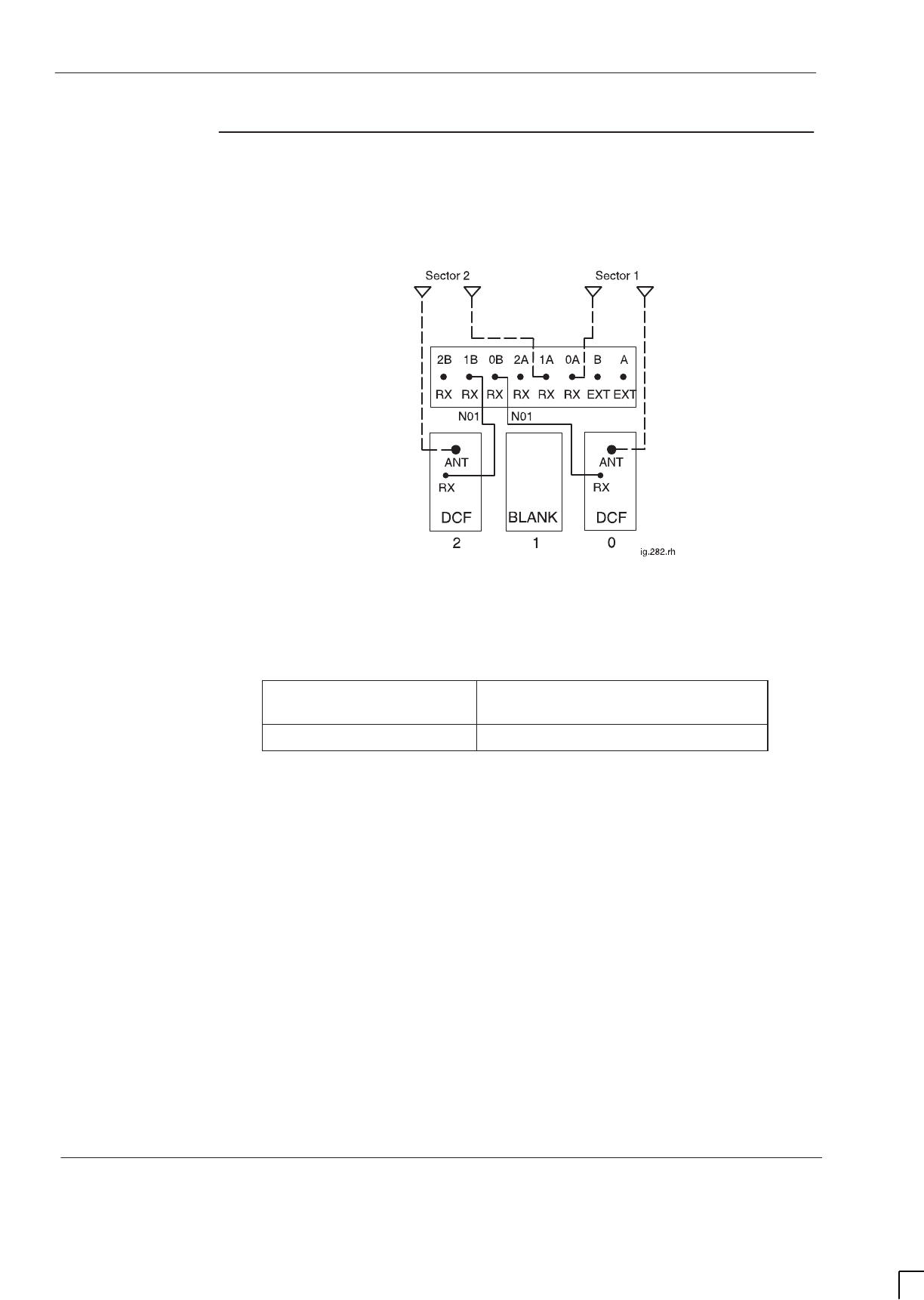
GSM-205-423
Suggested RF configurations
31st Oct 01
Inst. 2–30
Installation & Configuration: Horizon
macro
indoor
CONTROLLED INTRODUCTION
68P02902W08-B
Configuration
for sector 1/1 or
2/2
Figure 2-20 shows a suggested configuration, using a single Horizon
macro
cabinet, for sector 1/1 or 2/2 with duplexed combining bandpass filter.
Figure 2-20 Single cabinet sector 1/1 or 2/2 with DCF
Unused SMA connectors must be fitted with 50 ohm terminating loads as shown
below.
If configured for... Then 50 ohm load required on
unused SMA input to...
sector 1/1 DCF 0 and DCF 2
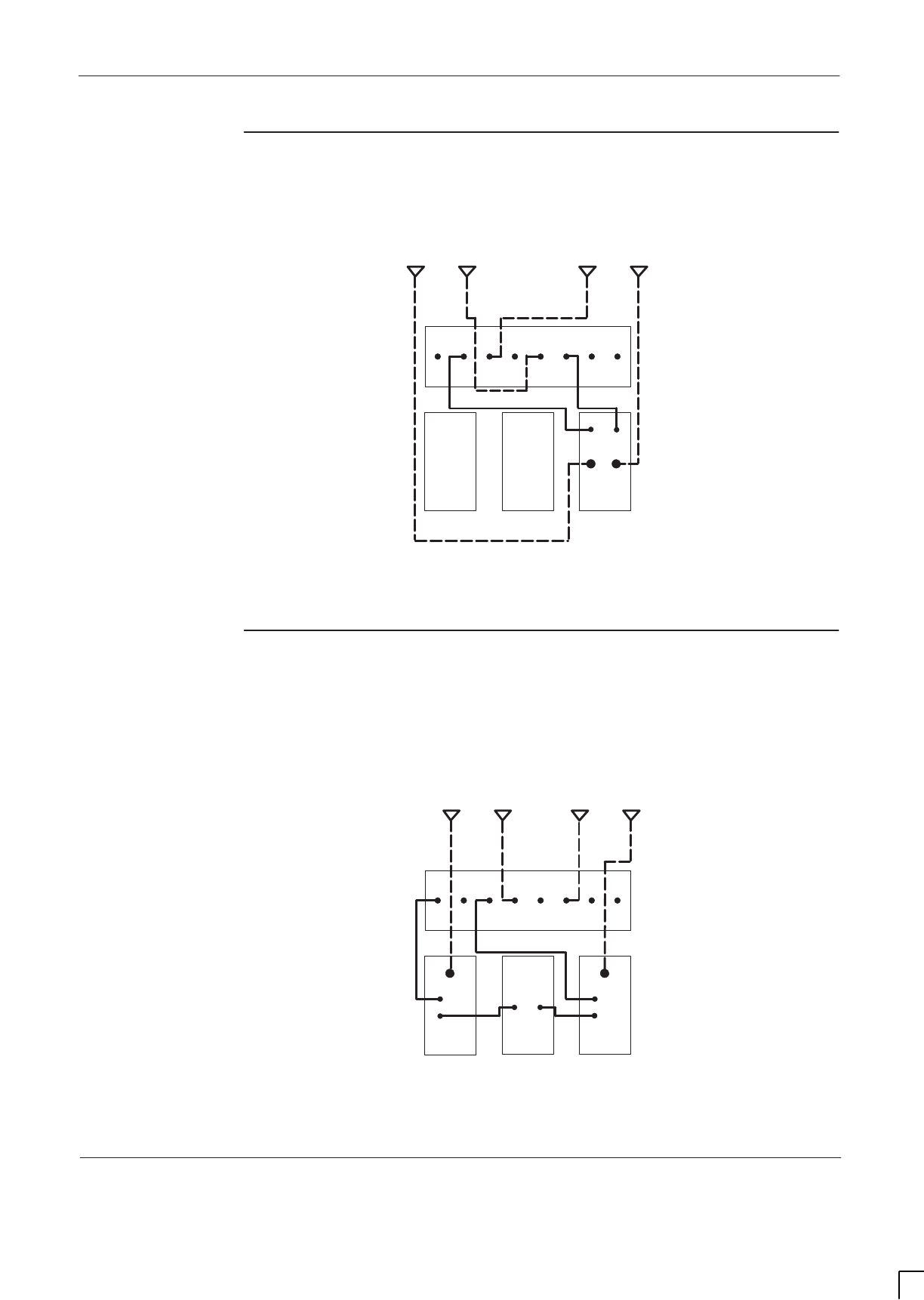
GSM-205-423 Suggested RF configurations
31st Oct 01
Installation & Configuration: Horizon
macro
indoor
68P02902W08-B
CONTROLLED INTRODUCTION
Inst. 2–31
Configuration
for sector 1/1
Figure 2-21 shows a suggested configuration, using one Horizon
macro
cabinet,
for sector 1/1 with twin duplexed filter.
SECTOR 2
B
EXT
RX
RX
RX
RX
RX
RX
EXT
A0A1A2A0B1B2B
20
ANT
RX
TDF
N01
1
RX
N01
SECTOR 1
BLANK
BLANK
ANT
Figure 2-21 Single cabinet sector 1/1 with TDF
Configuration
for single
cabinet sector
3/3
Figure 2-22 shows a suggested configuration, using one Horizon
macro
cabinet,
for sector 3/3 with dual stage duplexed combining filter.
SECTOR 1
B
EXT
RX
RX
RX
RX
RX
RX
EXT
A0A1A2A0B1B2B
N02
2
ANT
RX
DDF FEED
THRU
0
ANT
RX
DDF
N01
1
TX TXTX
N02
N01
SECTOR 2
Figure 2-22 Single cabinet sector 3/3 with DDF
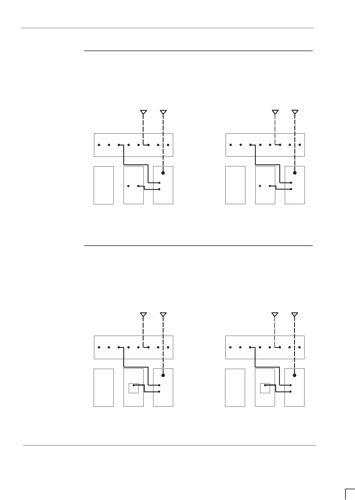
GSM-205-423
Suggested RF configurations
31st Oct 01
Inst. 2–32
Installation & Configuration: Horizon
macro
indoor
CONTROLLED INTRODUCTION
68P02902W08-B
Configuration
for 2 cabinet
sector 3/3
Figure 2-23 shows a suggested configuration, using two Horizon
macro
cabinets,
for sector 3/3 with dual stage duplexed combining filter.
SECTOR 1
B
EXT
RX
RX
RX
RX
RX
RX
EXT
A0A1A2A0B1B2B
2
BLANK
0
ANT
RX
DDF
N01
TXTX
N02
FEED
THRU
1
SECTOR 2
B
EXT
RX
RX
RX
RX
RX
RX
EXT
A0A1A2A0B1B2B
2
BLANK
0
ANT
RX
DDF
N01
TXTX
N02
FEED
THRU
1
Figure 2-23 Two cabinet sector 3/3 with DDF
Configuration
for 2 cabinet
sector 4/4
Figure 2-24 shows a suggested configuration, using two Horizon
macro
cabinets,
for sector 4/4 with dual stage duplexed combining filter and hybrid combining
unit.
SECTOR 1
B
EXT
RX
RX
RX
RX
RX
RX
EXT
A0A1A2A0B1B2B
2
BLANK
0
ANT
RX
DDF
N01
TXTX
N02
1
HCU
TX
SECTOR 2
B
EXT
RX
RX
RX
RX
RX
RX
EXT
A0A1A2A0B1B2B
2
BLANK
0
ANT
RX
DDF
N01
TXTX
N02
1
HCU
TX
Figure 2-24 Two cabinet sector 4/4 with DDF and HCU
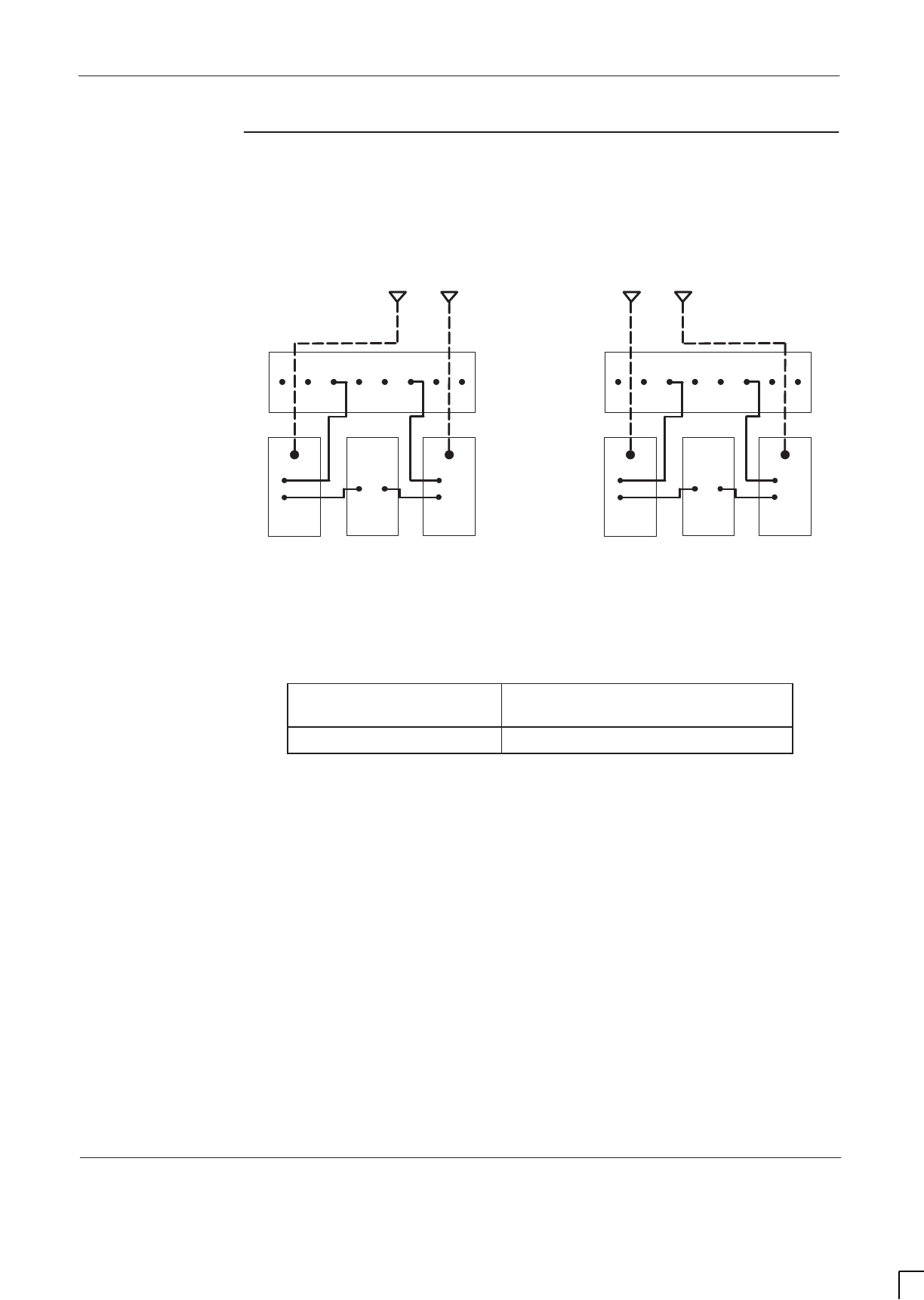
GSM-205-423 Suggested RF configurations
31st Oct 01
Installation & Configuration: Horizon
macro
indoor
68P02902W08-B
CONTROLLED INTRODUCTION
Inst. 2–33
Configuration
for 2 cabinet
sector 5/5 or 6/6
Figure 2-25 shows a suggested configuration, using two Horizon
macro
cabinets,
for sector 5/5 or 6/6 with dual stage duplexed combining filter and air combining.
SECTOR 2
B
EXT
RX
RX
RX
RX
RX
RX
EXT
A0A1A2A0B1B2B
N02
2
ANT
RX
DDF FEED
THRU
0
ANT
RX
DDF
N01
1
TX TXTX
N02
N01
SECTOR 1
B
EXT
RX
RX
RX
RX
RX
RX
EXT
A0A1A2A0B1B2B
N02
2
ANT
RX
DDF FEED
THRU
0
ANT
RX
DDF
N01
1
TX TXTX
N02
N01
Figure 2-25 Two cabinet sector 5/5 or 6/6 with DDF and air combining
Unused SMA connectors must be fitted with 50 ohm terminating loads as shown
below.
If configured for... Then 50 ohm load required on
unused SMA input to...
sector 5/5 both DDF 2 modules
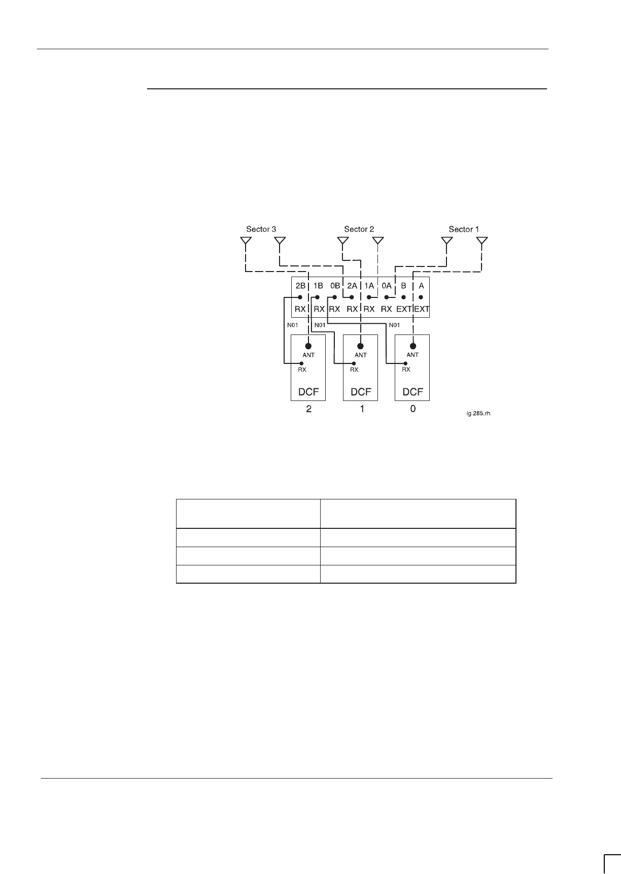
GSM-205-423
Suggested RF configurations
31st Oct 01
Inst. 2–34
Installation & Configuration: Horizon
macro
indoor
CONTROLLED INTRODUCTION
68P02902W08-B
Configuration
for single
cabinet sector
1/1/1, 1/1/2, 1/2/2
or 2/2/2
Figure 2-26 shows a suggested configuration, using a single Horizon
macro
cabinet, for sector 1/1/1, 1/1/2, 1/2/2 or 2/2/2 with duplexed combining
bandpass filter.
Figure 2-26 Single cabinet sector 1/1/1, 1/1/2, 1/2/2 or 2/2/2 with DCF
Unused SMA connectors must be fitted with 50 ohm terminating loads as shown
below.
If configured for... Then 50 ohm load required on
unused SMA input to...
Sector 1/1/1 DCF 0, 1 and 2
Sector 1/1/2 DCF 1 and 2
Sector 1/2/2 DCF 2
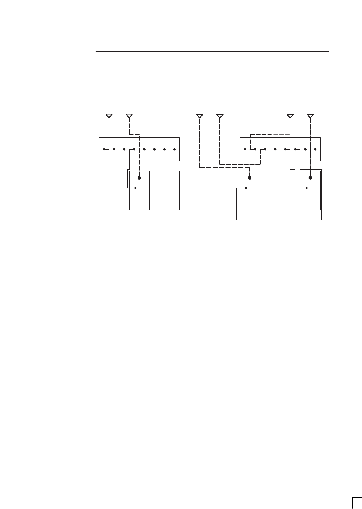
GSM-205-423 Suggested RF configurations
31st Oct 01
Installation & Configuration: Horizon
macro
indoor
68P02902W08-B
CONTROLLED INTRODUCTION
Inst. 2–35
Configuration
for 2 cabinet
sector 2/2/2
Figure 2-27 shows a suggested configuration, using two Horizon
macro
cabinets,
for sector 2/2/2 with duplexed combining bandpass filter.
SECTOR 1
SECTOR 2
SECTOR 3
B
EXT
RX
RX
RX
RX
RX
RX
EXT
A0A1A2A0B1B2B
N01
B
EXT
RX
RX
RX
RX
RX
RX
EXT
A0A1A2A0B1B2B
N01
2
ANT
RX
DCF BLANK
1
ANT
RX
DCF
0
BLANK
2
BLANK
0
ANT
RX
DCF
N01
Figure 2-27 Two cabinet sector 2/2/2 with DCF
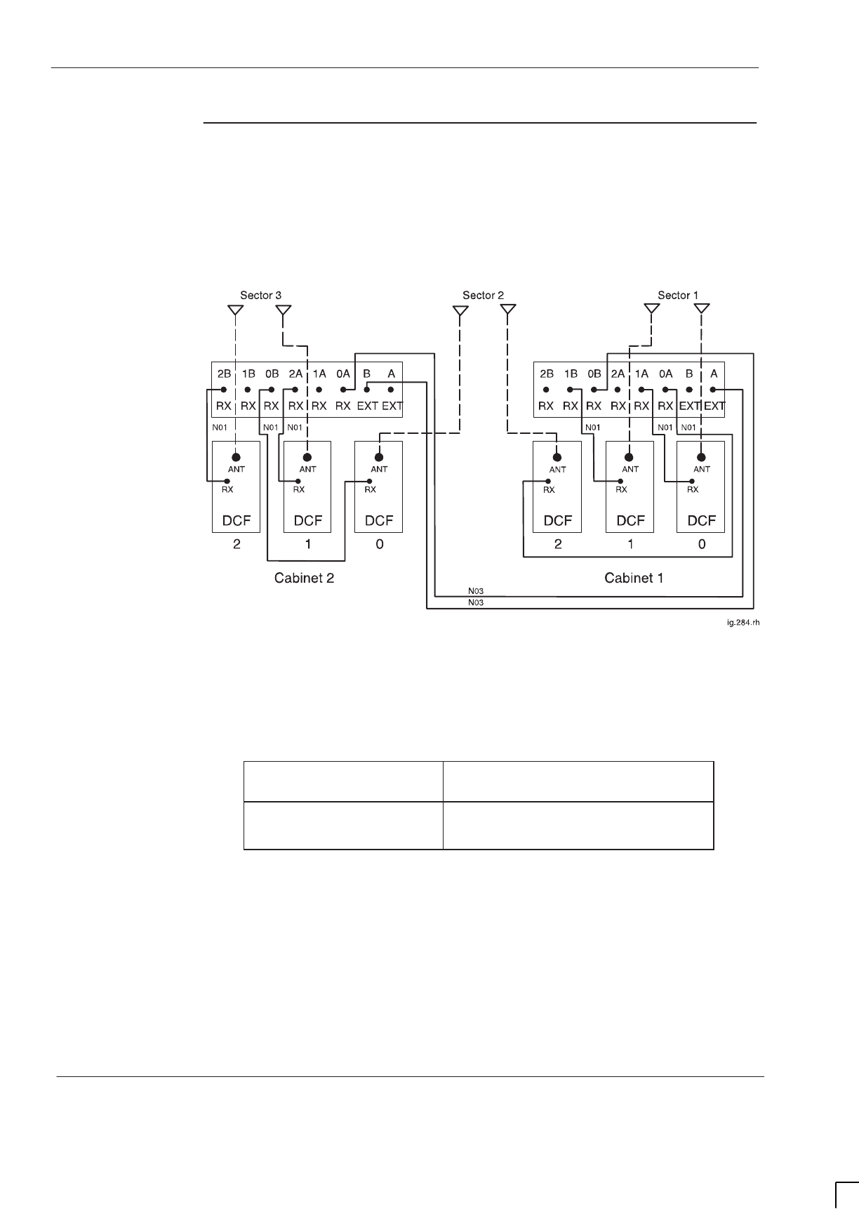
GSM-205-423
Suggested RF configurations
31st Oct 01
Inst. 2–36
Installation & Configuration: Horizon
macro
indoor
CONTROLLED INTRODUCTION
68P02902W08-B
Configuration
for 2 cabinet
sector 3/3/3 or
4/4/4
Figure 2-28 shows a suggested configuration, using two Horizon
macro
cabinets,
for sector 3/3/3 or sector 4/4/4 with duplexed combining bandpass filter and air
combining.
Figure 2-28 Two cabinet sector 3/3/3 or sector 4/4/4 with DCF and air
combining
Unused SMA connectors must be fitted with 50 ohm terminating loads as shown
below.
If configured for... Then 50 ohm load required on
unused SMA input to...
sector 3/3/3 cabinet 1, DCF 1
cabinet 2, DCF 0 and DCF 2
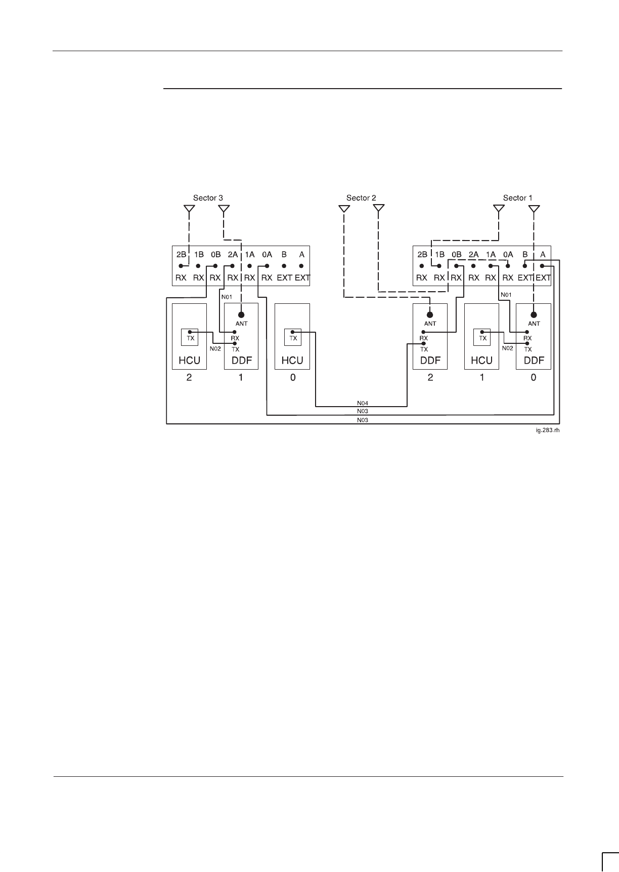
GSM-205-423 Suggested RF configurations
31st Oct 01
Installation & Configuration: Horizon
macro
indoor
68P02902W08-B
CONTROLLED INTRODUCTION
Inst. 2–37
Configuration
for 2 cabinet
sector 4/4/4
Figure 2-29 shows a suggested configuration, using two Horizon
macro
cabinets,
for sector 4/4/4 with dual stage duplexed combining filter and hybrid combining
unit.
Figure 2-29 Two cabinet sector 4/4/4 with DDF and HCU
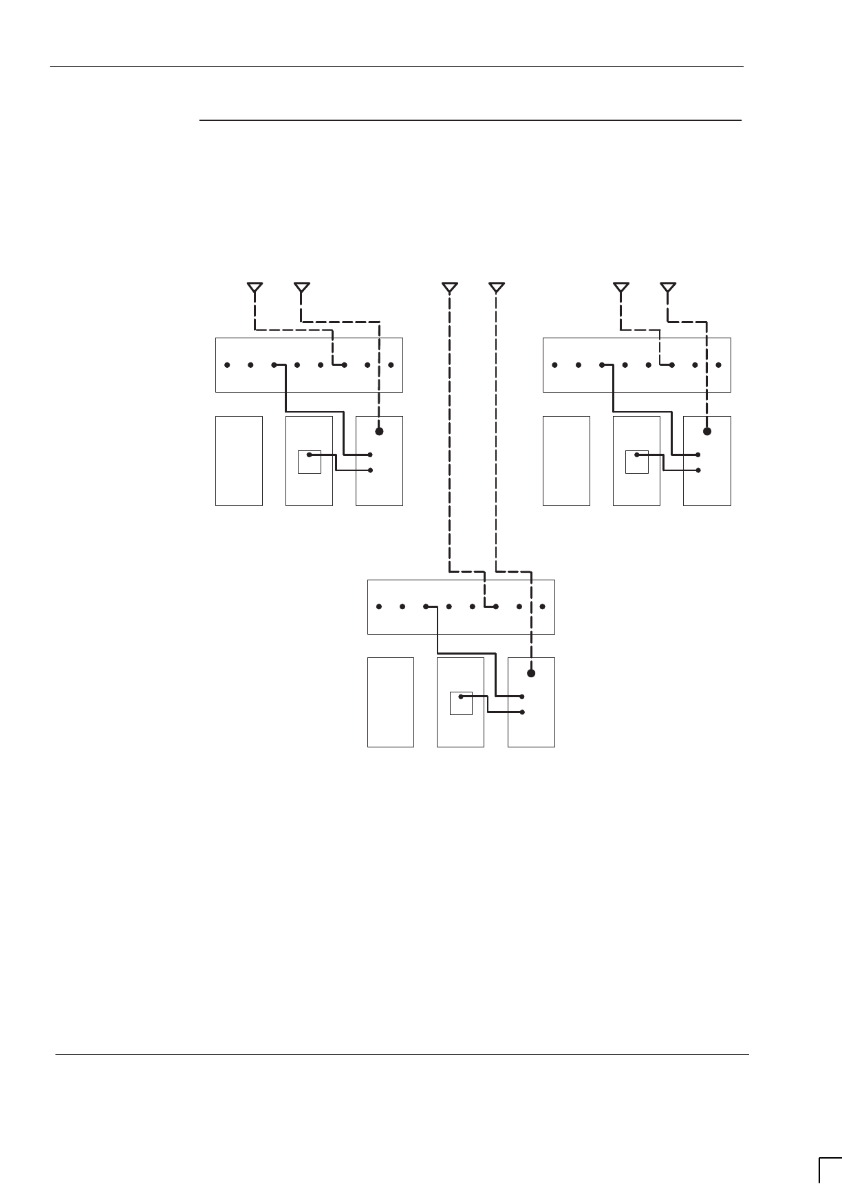
GSM-205-423
Suggested RF configurations
31st Oct 01
Inst. 2–38
Installation & Configuration: Horizon
macro
indoor
CONTROLLED INTRODUCTION
68P02902W08-B
Configuration
for 3 cabinet
sector 4/4/4
Figure 2-30 shows a suggested configuration, using three Horizon
macro
cabinets, for sector 4/4/4 with dual stage duplexed combining filter and hybrid
combining unit.
SECTOR 1
SECTOR 2 SECTOR 3
B
EXT
12 0
RX
RX
RX
RX
RX
RX
EXT
A0A1A2A0B1B2B
ANT
RX
N01
BLANK
TX
DDF
HCU
N02
TX
B
EXT
0
RX
RX
RX
RX
RX
RX
EXT
A0A1A2A0B1B2B
ANT
RX
N01
BLANK
TX
DDF
HCU
N02
TX
B
EXT
0
RX
RX
RX
RX
RX
RX
EXT
A0A1A2A0B1B2B
ANT
RX
N01
BLANK
TX
DDF
HCU
N02
TX
1212
Figure 2-30 Three cabinet sector 4/4/4 with DDF and HCU
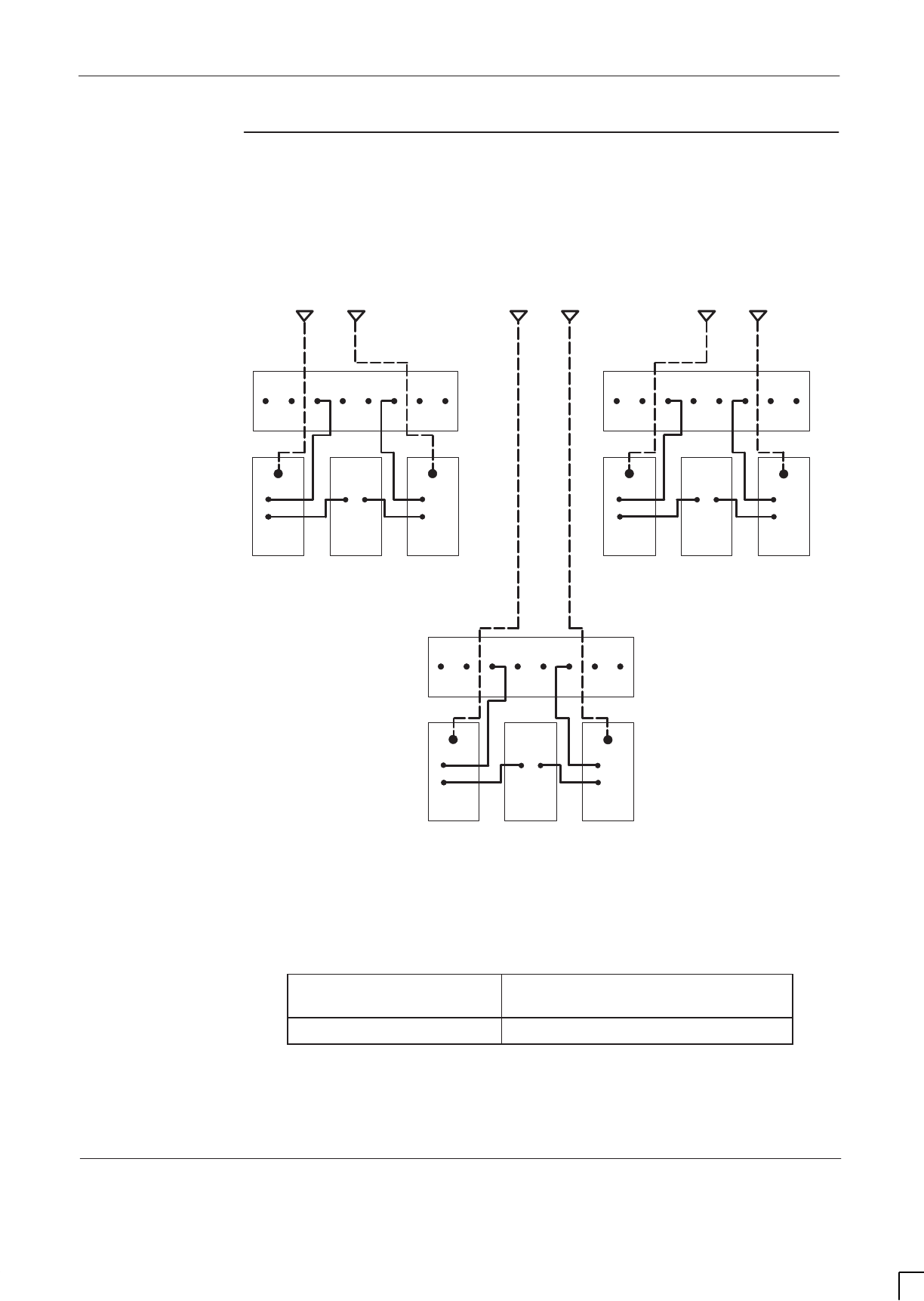
GSM-205-423 Suggested RF configurations
31st Oct 01
Installation & Configuration: Horizon
macro
indoor
68P02902W08-B
CONTROLLED INTRODUCTION
Inst. 2–39
Configuration
for sector 5/5/5
or 6/6/6
Figure 2-31 shows a suggested configuration, using three Horizon
macro
cabinets, for sector 5/5/5 or sector 6/6/6 with dual stage duplexed combining
filter and air combining.
B
EXT
12 0
N01 N01
ANT
RX
RX
RX
RX
RX
RX
EXT
A0A1A2A0B1B2BB
EXT
12 0
TX
ANT
DDF
TX
ANT
DDF
FEED
THRU
RX
RX
RX
RX
RX
RX
EXT
A0A1A2A0B1B2B
RX RX
N02 RX
ANT
RX
N01
N01
SECTOR 1
SECTOR 2 SECTOR 3
N02
TX
DDF
TX
DDF
FEED
THRU
N02 N02
B
EXT
12 0
ANT
RX
RX
RX
RX
RX
RX
EXT
A0A1A2A0B1B2B
RX
ANT
RX
N01
N01
TX
DDF
TX
DDF
FEED
THRU
N02 N02
Figure 2-31 Sector 5/5/5 or sector 6/6/6 with DDF and air combining
Unused SMA connectors must be fitted with 50 ohm terminating loads as shown
below.
If configured for... Then 50 ohm load required on
unused SMA input to...
sector 5/5/5 all DDF 2 modules
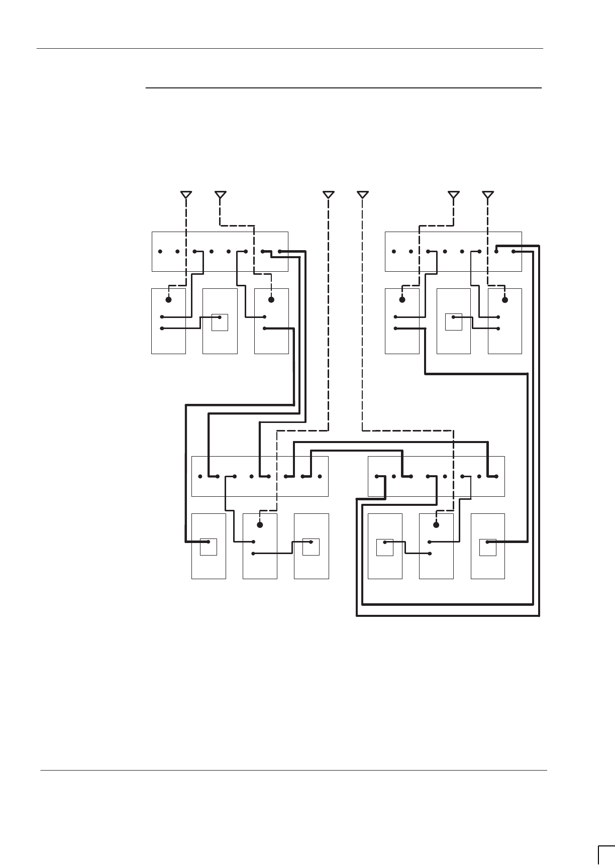
GSM-205-423
Suggested RF configurations
31st Oct 01
Inst. 2–40
Installation & Configuration: Horizon
macro
indoor
CONTROLLED INTRODUCTION
68P02902W08-B
Configuration
for sector 8/8/8
Figure 2-32 shows a suggested configuration, using four Horizon
macro
cabinets, for sector 8/8/8 with dual stage duplexed combining filter, hybrid
combining unit and air combining.
B
EXT
12 0
N01 N01
TX
ANT
DDF
RX
RX
RX
RX
RX
RX
EXT
A0A1A2A0B1B2B
B
EXT
12 0
HCU HCU
TX
ANT
DDF
RX
RX
RX
RX
RX
RX
EXT
A0A1A2A0B1B2B B
EXT
12 0
TX
ANT
DDF
RX
RX
RX
RX
RX
RX
EXT
A0A1A2A0B1B2B
B
EXT
12 0
TX
ANT
DDF
TX
ANT
DDF
TX
HCU
RX
RX
RX
RX
RX
RX
EXT
A0A1A2A0B1B2B
RX RX
N02
N03
N03
N04
TX
TX RX
N01
N02
HCU
TX RX
HCU
TX
N02
N01
N04
N03
N03
N03
N03N03N03
RX
TX
ANT
DDF
RX
TX
HCU
N01
N02
N01
SECTOR 1
SECTOR 2 SECTOR 3
Figure 2-32 Sector 8/8/8 with DDF, HCU and air combining
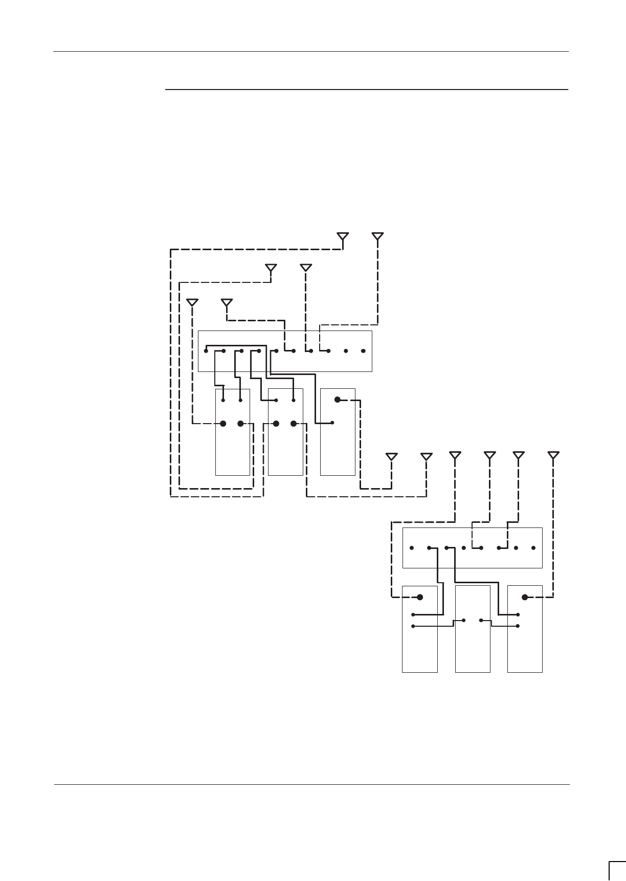
GSM-205-423 Suggested RF configurations
31st Oct 01
Installation & Configuration: Horizon
macro
indoor
68P02902W08-B
CONTROLLED INTRODUCTION
Inst. 2–41
Configuration
for dual band
1/1/1-3/3/3
Figure 2-33 shows a suggested configuration, using two Horizon
macro
cabinets,
for dual band sector 1/1/1–3/3/3 operation, where sector 1/1/1 is EGSM900 and
sector 3/3/3 is DCS1800. This dual band configuration requires one single band
1800 SURF and one dual band 900 SURF.
SECTOR 1
900
ANT
RX
900
TDF
RX
ANT
N01 N01
B
EXT
RX
RX
RX
RX
RX
RX
EXT
A0A1A2A0B1B2B
N02
2
ANT
RX
1800
DDF
FEED
THRU
0
ANT
RX
1800
DDF
N01
1
TX TXTX
N02
N01
B
EXT
RX
RX
RX
RX
RX
RX
EXT
A0A1A2A
1800
0A
0B1B
2 0
N01
1
1800
DCF
2B
1800
OB
RX
RX
RX
ANT
SECTOR 3
1800
N01
SECTOR 3
900
SECTOR 2
1800
DUAL
BAND
TDF
N01
RXRX
SECTOR 2
900
ANT
900
ANT
1800 SECTOR 1
1800
Figure 2-33 Two cabinet dual band sector 1/1/1-3/3/3
Unused SMA connectors must be fitted with 50 ohm terminating loads.
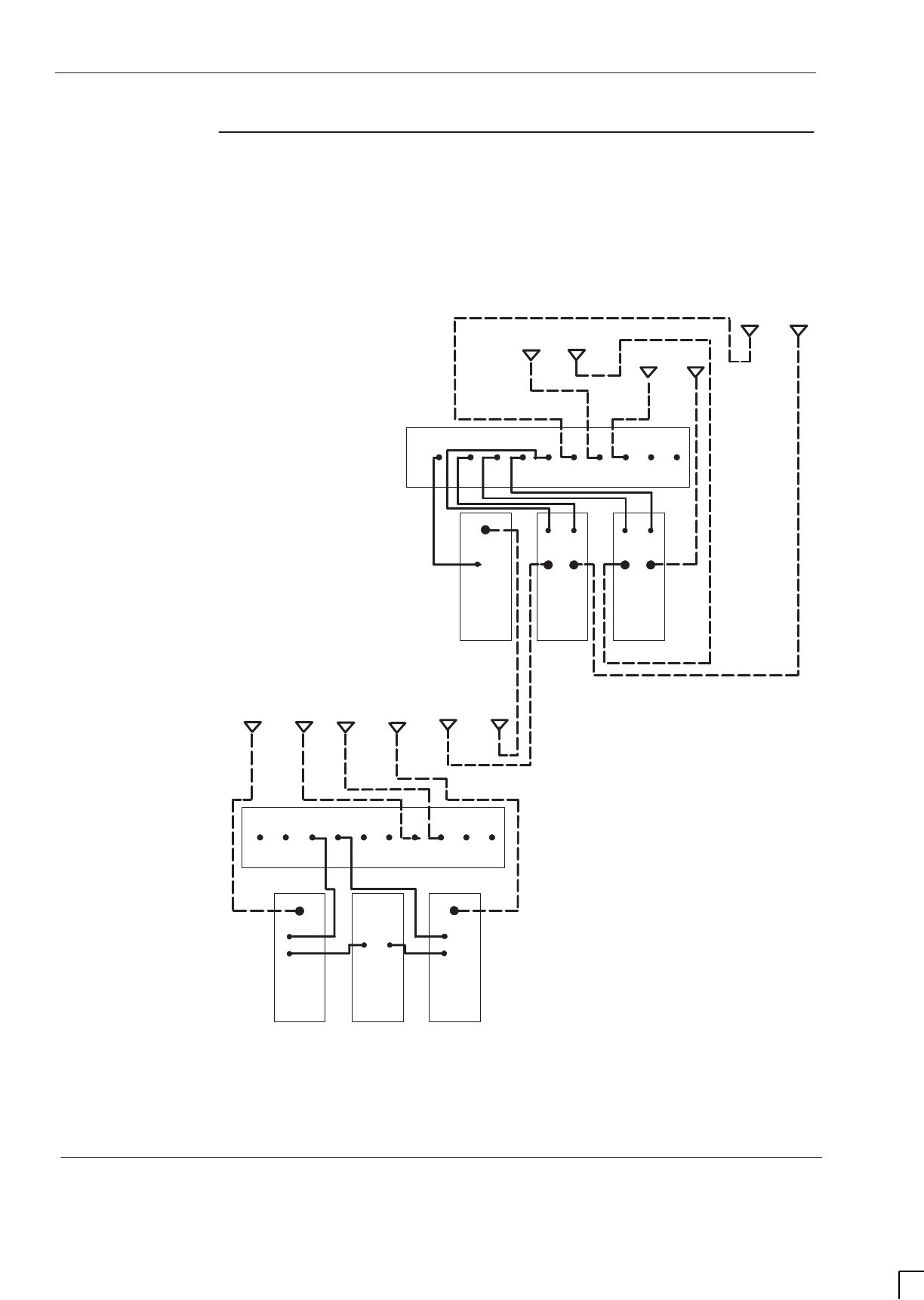
GSM-205-423
Suggested RF configurations
31st Oct 01
Inst. 2–42
Installation & Configuration: Horizon
macro
indoor
CONTROLLED INTRODUCTION
68P02902W08-B
Configuration
for dual band
3/3/3-1/1/1
Figure 2-34 shows a suggested configuration, using two Horizon
macro
cabinets,
for dual band sector 3/3/3–1/1/1 operation, where sector 3/3/3 is EGSM900 and
sector 1/1/1 is DCS1800. This dual band configuration requires one dual band
1800 SURF and one dual band 900 SURF.
RX
RX
B
EXT
RX
RX
RX
RX
EXT
A0A1A2A
1800
OA
0B1B
2B
1800
OB
RX
RX
SECTOR 1
900
SECTOR 3
900 SECTOR 2
900
900
DDF
900
DDF
RX
ANT
RX
FEED
THRU
ANT
RX
TX TXTX
900
0B
RX
RX
RX
ANT
RX RX
ANT
900
DCF 1800
TDF
SECTOR 1
1800
SECTOR 2
1800
SECTOR 3
1800
900
OA
0B
Tx1Rx0A
DUAL
BAND
TDF
Rx1A
Rx2A
20
1
B
EXT
RX
RX
RX
RX
EXT
A0A1A2A1B
20
1
2B
RX
ANT
900
RX RX
ANT
1800
Tx0 Tx2
RX
ANT
Figure 2-34 Two cabinet dual band sector 3/3/3-1/1/1
Unused SMA connectors must be fitted with 50 ohm terminating loads.

GSM-205-423 Connecting fibre optic cables
31st Oct 01
Installation & Configuration: Horizon
macro
indoor
68P02902W08-B
CONTROLLED INTRODUCTION
Inst. 2–43
Connecting fibre optic cables
Location of
fibre optic
connections
WARNING Do not look directly into a fibre optic cable or the data
in/out connectors of the FMUX or MCUF, with or without
the use of optical aids. Laser radiation can come from
either the data in/out connectors or unterminated fibre
optic cables connected to data in/out connectors.
In an installation configuration with more than one Horizon
macro
indoor cabinet,
fibre optic connections are used to link the MCUF in the master cabinet to the
extension cabinets. A maximum of three extension cabinets can be added to the
master cabinet.
Connections from the master cabinet are provided by three fibre optic
multiplexers (FMUXs). Two are located integral to the MCUF, and the third is a
separate module located in the slot next to the master MCUF. Additional
redundant modules may be installed for both MCUF and FMUX modules.
Extension cabinets have only a single FMUX, with optional redundancy, for fibre
optic connectivity to the master cabinet.
Tx and Rx data connections to the MCUF and FMUXs are located on the front
panel of each module.
Three different types of fibre optic cable, coloured orange and terminated with
ST fibre connectors, are available for use. These are described in Table 2-4.
Table 2-4 Extension cabinet fibre optic cables
Order
number Length Description
SVKN1244 5.6 m long connects master cabinet to first extension
SVKN1245 7.6 m long connects master cabinet to second extension
SVKN1246 7.6 m long connects master cabinet to third extension
Care of fibres
Optical fibre cables contain an inner core, which is a strand of glass coated by a
cladding (sometimes in two layers), and an outer protective sheath which
provides mechanical protection.
The fibre acts as a light waveguide. In order for the link to work correctly light
must be propagated with minimal losses from end-to-end of the fibre. A number
of problems can prevent this from happening, resulting in a potentially faulty link.
Care must be taken to ensure that the conditions that follow are met.

GSM-205-423
Connecting fibre optic cables
31st Oct 01
Inst. 2–44
Installation & Configuration: Horizon
macro
indoor
CONTROLLED INTRODUCTION
68P02902W08-B
Minimum bend radius
All optical fibres have a minimum bend radius. This represents the smallest
circle that is allowed to be formed from a loop of fibre, that is how tight it can be
coiled, looped or bent.
CAUTION Under no circumstances should fibres be bent tighter than
the minimum bend radius.
If fibres are bent tighter than the minimum bend radius then two possible effects
can happen:
SExcessive light loss can occur from the outside of the bend, resulting in a
loss of performance.
SThe fibre can fracture due to microscopic imperfections in the surface.
This type of break is invisible externally. If such a break occurs, excessive
light loss would be permanent and light would be scattered and reflected
from the break in the fibre. Returning the fibre to straight will not help and
the whole assembly will require replacement.
For glass fibres (orange or green outer sheath) the long term minimum bend
radius is approximately 30 mm.
Figure 2-35 illustrates the minimum bend radius for fibre optic cables.
30 mm
FIBRE OPTIC CABLE
Figure 2-35 Minimum bend radius of 30 mm
If the fibre is under tension (being stretched), the bend radius should be much
larger, at least doubled. This is because the tension in the fibre can increase the
possibilities of damage.
If in doubt about the radius, the fibre should be allowed to form its natural bend
radius by allowing it to bend under gravity only. This natural bend radius is
normally greater than 30 mm.

GSM-205-423 Connecting fibre optic cables
31st Oct 01
Installation & Configuration: Horizon
macro
indoor
68P02902W08-B
CONTROLLED INTRODUCTION
Inst. 2–45
Protecting fibres and connectors
To maintain good light transmission through the fibre optic link it is essential to
maintain cleanliness of the connector end surfaces and/or bare fibre ends.
At all times when fibres are not connected into the system, the connector
protective caps (normally red) should be fitted and kept in place. This is
especially important when routeing fibres during installation.
Cleaning fibres and connectors
Cleanliness of fibre terminations and connectors is essential. If cleaning of
contaminated optical components is required, then all areas should be wiped
gently with a lint free cloth soaked in a suitable cleaning solution. Care should
be taken to ensure the ends of the fibres are not scratched in any way, and are
completely dry before reconnection.
Connecting glass fibre cables
Fibre-ST connectors are used to terminate the fibre optic cables. These are
push fit and should not be tightened when connecting. Table 2-5 shows the fibre
optic interconnections between master and extension cabinets in multiple
cabinet sites.
Table 2-5 Fibre optic interconnections
Master cabinet
connection Extension
cabinet FMUX
connection
MCUF TCU0 FMUX0 IN 2nd cabinet DATA OUT
MCUF TCU0 FMUX0
OUT 2nd cabinet DATA IN
MCUF TCU1 FMUX1 IN 3rd cabinet DATA OUT
MCUF TCU1 FMUX1
OUT 3rd cabinet DATA IN
FMUX module DATA IN 4th cabinet DATA OUT
FMUX module DATA
OUT 4th cabinet DATA IN

GSM-205-423
Connecting fibre optic cables
31st Oct 01
Inst. 2–46
Installation & Configuration: Horizon
macro
indoor
CONTROLLED INTRODUCTION
68P02902W08-B
Connecting
fibre optic
cables between
cabinets
WARNING Do not look directly into a fibre optic cable or the data
in/out connectors of the FMUX or MCUF, with or without
the use of optical aids. Laser radiation can come from
either the data in/out connectors or unterminated fibre
optic cables connected to data in/out connectors.
To connect fibre optic cables between master and extension cabinets in multiple
cabinet sites.
1. Open master and extension cabinet doors and remove hoods, (if fitted).
CAUTION Under no circumstances should fibres be bent tighter than
the minimum bend radius.
2. Route the appropriate length extension cabinet fibre optic cable from the
digital module compartment of the master cabinet, through the aperture in
the right side of the CBIA cage, to the top section of the cabinet.
CAUTION Under no circumstances should any tools, such as pliers,
be used to connect ST fibre connectors.
3. Connect the push fit ST connector of the fibre optic cables to the
appropriate ports on the master MCUF, or master FMUX module, front
panel (see Table 2-5).
4. Route the fibre optic cable to the extension cabinet, following existing
cable layout as far as possible.
5. Pass the fibre optic cable through the fibre optic cable hole in the cabinet
top section to the extension cabinet FMUX.
6. Connect the push fit ST connector of the fibre optic cables to the data
ports on the extension cabinet master FMUX front panel.
7. Repeat steps 2 to 6 for digital redundancy MCUF and FMUX, if fitted.
8. Repeat steps 2 to 7 for additional extension cabinets.
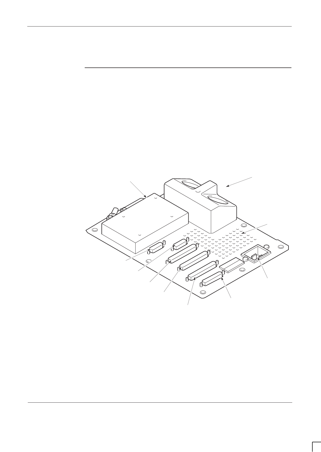
GSM-205-423 Interface panel cabling
31st Oct 01
Installation & Configuration: Horizon
macro
indoor
68P02902W08-B
CONTROLLED INTRODUCTION
Inst. 2–47
Interface panel cabling
Interface panel
diagram and
pinout
overview
All cabinet connectors are located on the interface panel. Each connector is
marked with the appropriate label. Power connectors are also located on the
interface panel.
An extension cabinet fibre optic cable is not connected to the interface panel,
but directly connected to the FMUX digital module in the CBIA cage. The fibre
optic cable enters the cabinet through a hole on the top panel in front of the
interface panel.
Figure 2-36 shows the locations of all the interface panel connectors.
ig.239.rh
T43/BIB
AC POWER
SOCKET INPUT
DC POWER
INPUT
GPS
(if fitted)
CCB
PIX 0
EXTERNAL ALARMS
PIX 1
ICS
VENTILATION
GRID
Figure 2-36 Interface panel connector locations

GSM-205-423
Interface panel cabling
31st Oct 01
Inst. 2–48
Installation & Configuration: Horizon
macro
indoor
CONTROLLED INTRODUCTION
68P02902W08-B
Connector
pinout tables
CAUTION Keep the plastic connector covers, supplied by Motorola,
on unused connectors to protect from damage by static or
foreign matter.
The following tables list the connector pinouts:
SExternal alarms see Table 2-6 and accompanying information.
SGPS see Table 2-7.
SCCB see Table 2-8.
SBIB see Table 2-9.
ST43 see Table 2-10.
SPIX0 see Table 2-11.
SPIX1 see Table 2-12.
SICS see Table 2-13.
NOTE Some pin connections only refer to indoor or outdoor
cabinets.
External alarm
connector
The external alarms connector is used by the battery backup system (BBS).
When this connector is not in use, a shorting plug, Motorola part number
2886169N01, is inserted. This plug must be removed to allow connection of the
alarm cable from the BSS and should be retained for refit during
decommissioning of BBS. The external alarm connector carries different alarms
in the Horizon
macro
outdoor.
The shorting plug joins pairs of pins as shown in Table 2-6.
Table 2-6 External alarms indoor pin shorts (37-way D-type)
Pin Nos Pin Nos Pin Nos Pin Nos
1 + 2 11 21+22 32
3 +4 12 23+24 33
5+6 13+14 25+26 34
7+8 15+16 27+28 35
9 17+18 29+30 36+37
10 19 +20 31

GSM-205-423 Interface panel cabling
31st Oct 01
Installation & Configuration: Horizon
macro
indoor
68P02902W08-B
CONTROLLED INTRODUCTION
Inst. 2–49
GPS connector
Table 2-7 lists the GPS connector pinouts.
NOTE The GPS connector is optional on later BTS cabinets.
Table 2-7 GPS pin connections (15-way D-type)
Pin
No Signal/Description Pin
No Signal/Description
1GPS power 1 9GPS power 2
2Not connected 10 Not connected
3chassis earth 11 PPS positive
4Tx negative 12 PPS negative
5Tx positive 13 Rx positive
6Rx negative 14 VPP
7 Earth 15 GPS return 2
8GPS return 1
CCB connector
Table 2-8 lists the CCB connector pinouts. This provides a single connector, to
provide power for up to two CCBs.
NOTE The CCB connector is not currently used on GSM850 or
PCS1900 BTS variants.
Table 2-8 CCB pin connections (15-way D-type)
Pin
No Signal/Description Pin
No Signal/Description
1Not connected 9Not connected
2Not connected 10 Not connected
3CCB0 27 V 11 Earth
4CCB0 27 V 12 Earth
5Not connected 13 Not connected
6CCB1 27 V 14 Earth
7CCB1 27 V 15 Earth
8Not connected
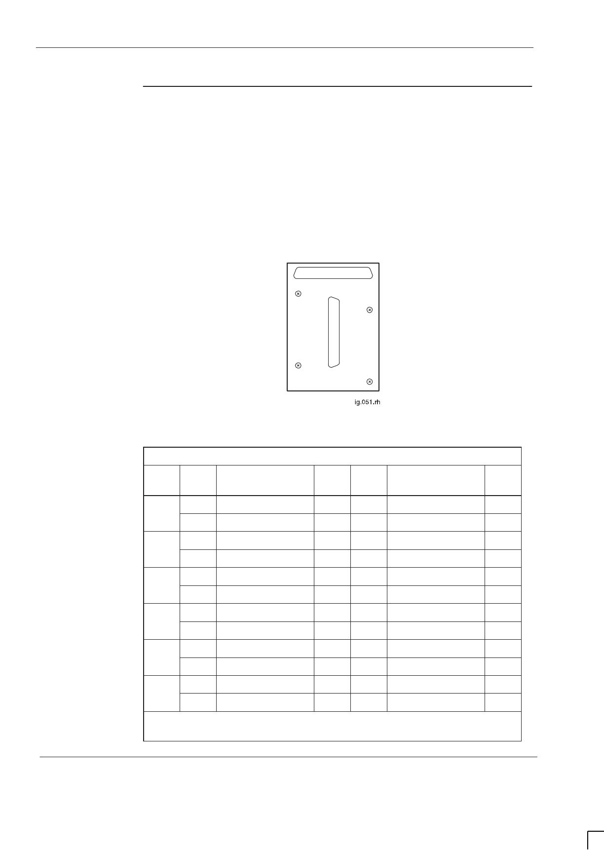
GSM-205-423
Interface panel cabling
31st Oct 01
Inst. 2–50
Installation & Configuration: Horizon
macro
indoor
CONTROLLED INTRODUCTION
68P02902W08-B
BIB (BIM)
interconnection
The Balanced-line Interconnect Board (BIB), also known as BIM, provides the
line isolation between the E1/T1 circuit lines and the CBIA backplane. The
board provides an interface for up to six input and six output balanced 120 ohm
lines. 12 transformers are used to provide line isolation while maintaining
impedance matching between the E1/T1 circuit lines and the NIU module. Each
transformer has a 1:1 turns ratio to match the external and backplane 120 ohm
connections.
Connection is made using a 37-pin D-type connector to both the BIB and the
external PCM twisted pair circuit lines. Figure 2-37 shows a typical BIB and
Table 2-9 lists BIB interconnections:
J1
J0
Figure 2-37 Balanced-line interconnect board (BIB)
Table 2-9 BIB interconnections
NIU/
port Pin
no Equipment/Ext Pin
no Pin
no Equipment/Ext Pin
no
A0/0 J0-1 Tx1+ J1-1 J0-20 Tx1– J1-20
J0-2 Rx1+ J1-2 J0-21 Rx1– J1-21
B0/0 J0-4 Tx4+ J1-4 J0-23 Tx4– J1-23
j0-5 Rx4+ J1-5 J0-24 Rx4– J1-24
A0/1 J0-7 Tx2+ J1-7 J0-26 Tx2– J1-26
J0-8 Rx2+ J1-8 J0-27 Rx2– J1-27
B0/1 j0-10 Tx5+ J1-10 J0-29 Tx5– J1-29
j0-11 Rx5+ J1-11 J0-30 Rx5– J1-30
A1/0 J0-13 Tx3+ J1-13 J0-32 Tx3– J1-32
J0-14 Rx3+ J1-14 J0-33 Rx3– J1-33
B1/0 J0-16 Tx6+ J1-16 J0-35 Tx6– J1-35
J0-17 Rx6+ J1-17 J0-36 Rx6– J1-36
Connector J0 and J1 pins 3,6,9,12,15,18,19, 22, 25, 28, 31, 34 and 37 are
connected to earth
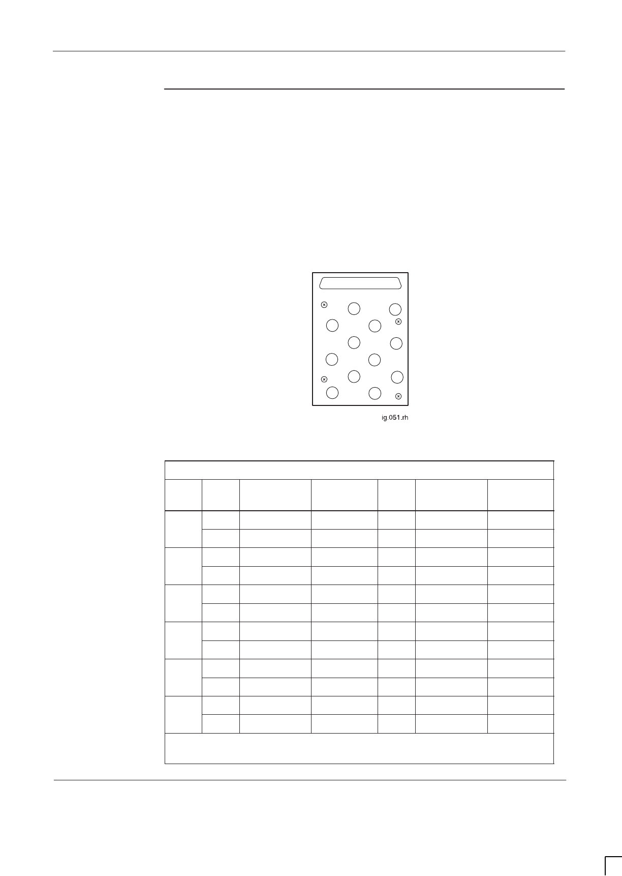
GSM-205-423 Interface panel cabling
31st Oct 01
Installation & Configuration: Horizon
macro
indoor
68P02902W08-B
CONTROLLED INTRODUCTION
Inst. 2–51
T43 (CIM)
interconnection
The Type 43 Interconnect Board (T43), also known as CIM, provides the
impedance matching and line isolation between the E1/T1 circuit lines and the
CBIA backplane. The board provides an interface for up to six input and six
output unbalanced coaxial 75 ohm lines. 12 transformers are used to provide
impedance matching and line isolation between the E1/T1 circuit lines and the
NIU module. Each transformer has a 1:1.25 turns ratio to match the external 75
ohm and backplane 120 ohm connections.
Connection is made using a 37-pin D-type connector to the interconnect board
and twelve type 43 coaxial connectors to the external E1/T1 circuit lines.
Figure 2-38 shows a typical T43, and Table 2-10 lists the T43 interconnections.
J1
J2
J5
J4
J7
J8
J10
J13 J11
J14
J16
J17
J0
Figure 2-38 Type 43 interconnect board (T43)
Table 2-10 T43 interconnections
NIU/
port Pin
no Equipment
/ Ext Pin no Pin
no Equipment
/ Ext Pin no
A0/0 J0-1 Tx1+ J1 centre J0-20 Tx1– J1 shield
J0-2 Rx1+ J2 centre J0-21 Rx1– J2 shield
B0/0 J0-4 Tx4+ J4 centre J0-23 Tx4– J4 shield
j0-5 Rx4+ J5 centre J0-24 Rx4– J5 shield
A0/1 J0-7 Tx2+ J7 centre J0-26 Tx2– J7 shield
J0-8 Rx2+ J8 centre J0-27 Rx2– J8 shield
B0/1 j0-10 Tx5+ J10 centre J0-29 Tx5– J10 shield
j0-11 Rx5+ J11 centre J0-30 Rx5– J11 shield
A1/0 J0-13 Tx3+ J13 centre J0-32 Tx3– J13 shield
J0-14 Rx3+ J14 centre J0-33 Rx3– J14 shield
B1/0 J0-16 Tx6+ J16 centre J0-35 Tx6– J16 shield
J0-17 Rx6+ J17 centre J0-36 Rx6– J17 shield
Connector J0 pins 3,6,9,12,15,18,19, 22, 25, 28, 31, 34 and 37 are not
used

GSM-205-423
Interface panel cabling
31st Oct 01
Inst. 2–52
Installation & Configuration: Horizon
macro
indoor
CONTROLLED INTRODUCTION
68P02902W08-B
PIX conditions
input/output
PIX outputs
PIX outputs comprise 4 relay contacts controlled by the alarm board and MCUF.
The relays have multiple contacts, some normally open and some normally
closed. The contacts are rated for 1A at 30 V. The contacts may be used for
control of external equipment such as fans or audible alarms.
PIX inputs
PIX inputs comprise 16 connections to external sensors. These inputs report
alarms to the BSC, via the alarm board and MCUF, which forwards the alarms to
the OMC-R. The end-user supplies the external sensors. Each sensor connects
across an opto-coupled pair of PIX inputs (eight per PIX connector).
All sensors must be dry-contact type with the following specification:
S5 kohms or greater across sense inputs for logic 1 (PIX opto-coupler off).
S500 ohms or less across sense inputs for logic 0 (PIX opto-coupler on).
Table 2-11 shows PIX0 connections and Table 2-12 shows PIX1 connections.
Table 2-11 PIX0 pin connections (37-way D-type)
Pin
No Signal/Description Pin
No Signal/Description
1Site input Ext 1–1 19 Not connected
2Site input Ext 2–1 20 Site input Ext 1–2
3Site input Ext 3–1 21 Site input Ext 2–2
4Site input Ext 4–1 22 Site input Ext 3–2
5Site input Ext 5–1 23 Site input Ext 4–2
6Site input Ext 6–1 24 Site input Ext 5–2
7Site input Ext 7–1 25 Site input Ext 6–2
8Site input Ext 8–1 26 Site input Ext 7–2
9Not connected 27 Site input Ext 8–2
10 Not connected 28 spare
11 Site output relay 1 – NO 29 Site output relay 1 – NC
12 Site output relay 2 – NO 30 Site output relay 1 – COM
13 Site output relay 2 – NC 31 Site output relay 2 – COM
14 Site output relay 3 – NO 32 Site output relay 3 – NC
15 Site output relay 4 – NO 33 Site output relay 3 – COM
16 Site output relay 4 – NC 34 Site output relay 4 – COM
17 Not connected 35 Not connected
18 Not connected 36/37 Not connected

GSM-205-423 Interface panel cabling
31st Oct 01
Installation & Configuration: Horizon
macro
indoor
68P02902W08-B
CONTROLLED INTRODUCTION
Inst. 2–53
Table 2-12 PIX1 pin connections (37-way D-type)
Pin
No Signal/Description Pin
No Signal/Description
1Site input Ext 9–1 19 Not connected
2Site input Ext 10–1 20 Site input Ext 9–2
3Site input Ext 11–1 21 Site input Ext 10–2
4Site input Ext 12–1 22 Site input Ext 11–2
5Site input Ext 13–1 23 Site input Ext 12–2
6Site input Ext 14–1 24 Site input Ext 13–2
7Site input Ext 15–1 25 Site input Ext 14–2
8Site input Ext 16–1 26 Site input Ext 15–2
9Not connected 27 Site input Ext 16–2
Pins 10 to 18 not connected Pins 28 to 37 not connected
ICS connector
Table 2-13 lists the Integrated Cell Site (ICS) connector pinouts. This is a future
feature.
Table 2-13 ICS pin connections (25-way D-type)
Pin
No Signal/Description Pin
No Signal/Description
1ICS0 TTY earth 10 ICS3 TTY earth
2ICS0 TTY Rx 11 ICS3 TTY Rx
3ICS0 TTY Tx 12 ICS3 TTY Tx
4ICS1 TTY earth 13 ICS4 TTY earth
5ICS1 TTY Rx 14 ICS4 TTY Rx
6ICS1 TTY Tx 15 ICS4 TTY Tx
7ICS2 TTY earth 16 ICS5 TTY earth
8ICS2 TTY Rx 17 ICS5 TTY Rx
9ICS2 TTY Tx 18 ICS5 TTY Tx
Pins 19 to 25 not connected

GSM-205-423
Installing and connecting power and earth cabling
31st Oct 01
Inst. 2–54
Installation & Configuration: Horizon
macro
indoor
CONTROLLED INTRODUCTION
68P02902W08-B
Installing and connecting power and earth cabling
Overview of
power and earth
cabling
This section describes the procedure for connecting power and earth cabling to
the cabinet.
WARNING Use the earth stud, located on the interface panel on the
top of the cabinet, to earth the cabinet.
Do not daisy chain cabinet earths together.
Cabinets must be earthed with a conductor capable of
carrying the full fault current of the overcurrent protection
device.
Do not make input power connections at the main power
source at this time. Connecting input power is the final
installation procedure in this chapter.
Power specifications can be found in Chapter 2 Site requirements and
considerations.
Cable routeing
CAUTION Ensure that covers are fitted to any unused connectors on
the cabinet interconnect panel; the covers protect the
connectors from damage by static electricity or foreign
matter.
Do not make dc input power connections at the main dc
power source at this time.
The external converter supplying power to the cabinet
must have double or reinforced insulation between its
primary and secondary circuits.
The external converter that supplies power to the cabinet
must meet safety standard EN 60950.
An adequate means should be provided for routeing cables from the main
power source to the equipment, such as a cable trough or conduit.
NOTE The current-carrying capacity of a cable for continuous
service is affected by all of the following factors (reference
IEC 364):
– Ambient temperature.
– Grouping.
– Partial or total enclosure in thermal insulating material.
– Frequency (ac only).

GSM-205-423 Installing and connecting power and earth cabling
31st Oct 01
Installation & Configuration: Horizon
macro
indoor
68P02902W08-B
CONTROLLED INTRODUCTION
Inst. 2–55
Cabinet and
ESP earthing
points
The main earth connection point is on the top interface panel, with a 10 mm M6
threaded stud, adjacent to the dc input. This connection is for protective
earthing and functional earthing of the cabinet.
Additional internal earths are:
SDoor to cabinet frame.
SMain cage to interface panel above PSM.
STx block top panel to interface panel, near dc input.
SAC input connector to interface panel at rear of panel.
SEnclosure to interface panel, at rear near dc input.
An earthing wrist strap must be worn when handling electronic modules,
including the MCUF, FMUX, NIU, alarm module, CTU, and SURF. An ESP
earthing connection point is provided above the leftmost PSM.
Power supply
cable colour
coding
CAUTION Ensure correct PSMs are fitted to match the supply source
voltage.
+27 V dc cabinets
To connect a +27 V dc (negative earth) cabinet to the main dc power source.
Observe the following rules:
SThe 27 volt (+ve) power cable is red.
SThe 0 volt (–ve) cable is black.
–48/60 V dc cabinets
To connect a –48/60 V dc (positive earth) cabinet to the main dc power source,
Motorola recommends using a 35 sq. mm dc input power cable with a maximum
length of 24 m. Observe the following rules:
SThe –48/60 volt (–ve) power cable is blue.
SThe 0 volt (+ve) cable is black.

GSM-205-423
Installing and connecting power and earth cabling
31st Oct 01
Inst. 2–56
Installation & Configuration: Horizon
macro
indoor
CONTROLLED INTRODUCTION
68P02902W08-B
+ 27 V dc
connection
procedure
To connect dc power cables to a + 27 V dc cabinet:
WARNING Each cabinet must be earthed separately and not daisy
chained together.
1. Route the earth wire from the building master earth and connect to the
earth stud on top of the cabinet. Tighten to correct torque (see
Installation
& Configuration: GSM-205-423
Site requirements and considerations).
WARNING Do not make input power connections at the main power
source at this time. Connecting input power is the final
installation procedure in this chapter.
2. Thread the cone-shaped plastic covers onto the cables before connection.
3. Connect the black 0 volt (–ve) dc power cable to the cabinet dc power
connector assembly 0 V terminal, and route to the main dc power source.
4. Connect the red 27 volt (+ ve) dc power cable to the cabinet dc power
connector assembly V IN terminal, and route to the main dc power source.
5. Tighten the dc power connections (nuts on studs with star washers) to
correct torque as in step 1.
The + 27 volt dc power cable connection procedure is now complete.

GSM-205-423 Installing and connecting power and earth cabling
31st Oct 01
Installation & Configuration: Horizon
macro
indoor
68P02902W08-B
CONTROLLED INTRODUCTION
Inst. 2–57
– 48/60 V dc
connection
procedure
To connect dc power cables to a –48/60 V dc cabinet:
WARNING Each cabinet must be earthed separately and not daisy
chained together.
1. Route the earth wire from the building master earth and connect to the
earth stud on top of the cabinet. Tighten to the correct torque (see
Installation & Configuration: GSM-205-423
Site requirements and
considerations).
WARNING Do not make input power connections at the main power
source at this time. Connecting input power is the final
installation procedure in this chapter.
2. Thread the cone-shaped plastic covers onto the cables before connection.
3. Connect the black 0 volt (+ve) dc power cable to the cabinet dc power
connector assembly 0 V terminal, and route to the main dc power source
4. Connect the blue –48/60 volt (–ve) dc power cable to the cabinet dc power
connector assembly V IN terminal, and route to the main dc power source.
5. Tighten the dc power terminal connections (nuts on studs with star
washers) to correct torque as in step 1.
The –48/60 volt dc power cable connection procedure is now complete.
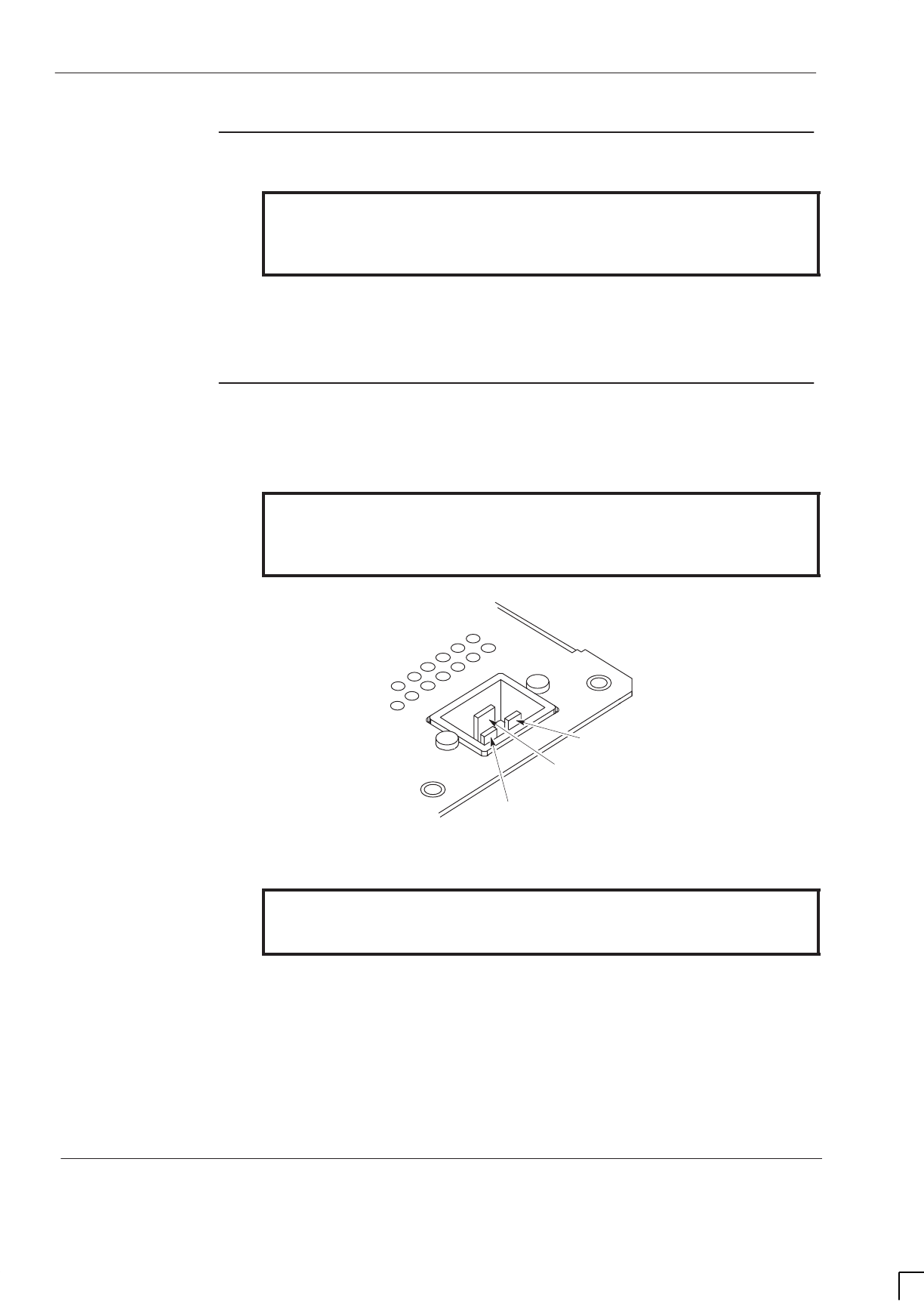
GSM-205-423
Installing and connecting power and earth cabling
31st Oct 01
Inst. 2–58
Installation & Configuration: Horizon
macro
indoor
CONTROLLED INTRODUCTION
68P02902W08-B
Cabinet ac
install
WARNING For connection to ac supply, use correct socket type,
protective device and appropriately rated cable, selected
in accordance with National and regional wiring
regulations.
The 230 volt ac input is via a recessed plug connector, rated at 20 amps, into
which an ac supply cable terminated with a standard type IEC320 socket may
be connected.
AC input
connection
Figure 2-39 shows the ac input connection located on the interface panel. The
live, neutral and earth connections are clearly marked.
WARNING If assembling a cable and socket for connection to this ac
input, ensure live, neutral and earth connections within the
socket match equivalent plug connections. That is, live
connects to live, neutral to neutral and earth to earth.
EARTH
NEUTRAL
LIVE
Figure 2-39 View of ac input recessed plug connector
WARNING Do not make ac input power connections at the main
power source at this time. Connecting input power is the
final installation procedure in this chapter.

GSM-205-423 Connecting input power
31st Oct 01
Installation & Configuration: Horizon
macro
indoor
68P02902W08-B
CONTROLLED INTRODUCTION
Inst. 2–59
Connecting input power
Pre-connection
checks
At this point in the installation, ensure that:
SThe cabinet is not already connected to the main ac or dc power source.
SThe cabinet is connected to the ac or dc power cabling.
Connecting dc
power
To connect dc power to a cabinet:
WARNING Do not wear an anti static wrist strap while servicing the
power supplies or power distribution cabling, as serious
personal injury can result. The external converter
supplying the cabinet must have double or reinforced
insulation between its primary and secondary circuits, and
must conform to Safety Standard EN 60950.
CAUTION Perform any adjustments recommended by the
manufacturer on the main power supply equipment before
connecting dc power cables to the main dc power source.
Input to the base station must remain between 20 V and
30 V under all load conditions for normal +27 V dc
operation.
Input to the base station must remain between –40 V and
–60 V dc for –48 V dc operation.
1. Turn off the main dc power supply.
2. Use a digital voltmeter to ensure that power is not present.
3. Route and secure the dc power and earth cables to the building ac power
supply from the cabinet.
4. Connect the earth wire to the building master earth.
5. Connect the 0 volt lead of the input dc power cable to the 0 volt terminal of
the main dc power supply. See Installing and connecting power and
earth cabling.
6. Connect the V IN lead of the input dc power cable to the V IN (+ 27 or
–48/60 volt, as appropriate for cabinet PSM type) terminal of the main dc
power supply. See Installing and connecting power and earth cabling.
7. Tighten connections to correct torque (see Site specific or electricity
supply company documentation).

GSM-205-423
Connecting input power
31st Oct 01
Inst. 2–60
Installation & Configuration: Horizon
macro
indoor
CONTROLLED INTRODUCTION
68P02902W08-B
Connecting ac
power
WARNING Ensure the ac power supply input has been safely
isolated, so that there is no risk of power being applied to
the cable during this procedure. The source should be
isolated and locked, and warning label attached.
To connect ac power to a cabinet:
1. Isolate the ac power source and lock the isolator switch.
WARNING Do not make input power connections at the main power source
at this time. Connecting to ac power source is the final step in
this procedure.
2. Route and secure the power cable from the building ac power supply to
the cabinet, near the interface panel.
3. Insert the ac power connector into the ac power socket on the cabinet.
4. Connect the ac power cable to the building power supply socket.
Ensure that all correct Request for connection and Completion and
inspection form certificates have been sent to the local electricity supply board.

GSM-205-423 Installing a hold-up battery module
31st Oct 01
Installation & Configuration: Horizon
macro
indoor
68P02902W08-B
CONTROLLED INTRODUCTION
Inst. 2–61
Installing a hold-up battery module
Introduction to
hold-up module
installation
The hold-up battery module is an optional item fitted in the PSM shelf within the
CBIA main cage, in any empty slot or in place of the redundant PSM. It may be
installed at the same time as the Horizon
macro
BTS or retrospectively. There is
no requirement to take the BTS out of service to retrofit the hold-up battery
module.
Installing a
hold-up battery
module
WARNING The batteries are capable of supplying high short circuit
currents and as such present a high energy hazard.
To install a hold-up battery module:
1. Check that the hold-up battery module enable switch is set to O (off).
2. Cut the cable tie that secures the jumper lead to the isolation connection
access hatch. Open the access hatch by turning the fastener a quarter
turn anticlockwise and lifting.
3. Fit the jumper lead between the battery spade terminals as shown in
Figure 2-40. Close the access hatch and turn the fastener a quarter turn
clockwise to secure.
4. Set switch of the redundant PSM, (if fitted) to OUTPUT DISABLE. The
ACTIVE LED (green) will extinguish. The ALARM LED (red) will light, or if
already lit due to alarm state, will stay on.
5. Remove redundant PSM or blanking assembly from the spare slot, by
unscrewing attachment screws with a torxdriver.
WARNING The hold-up battery module weighs 5.9 kg. Handle with
care.
6. Insert hold-up battery module in spare slot.
7. Ensure hold-up battery module is firmly in position and tighten both
module attachment screws using a torxdriver. Tighten to a torque of
2.2 Nm.
8. Set the hold-up battery module enable switch to I (on). Check that the
CHARGE LED (green) is lit.
NOTE The ACTIVE LED (green) will not light until 1.5 to 2 hours
after installation. The ALARM LED (red) may also be lit if
the initial battery voltage is below 19 V dc (+/–0.25 V).
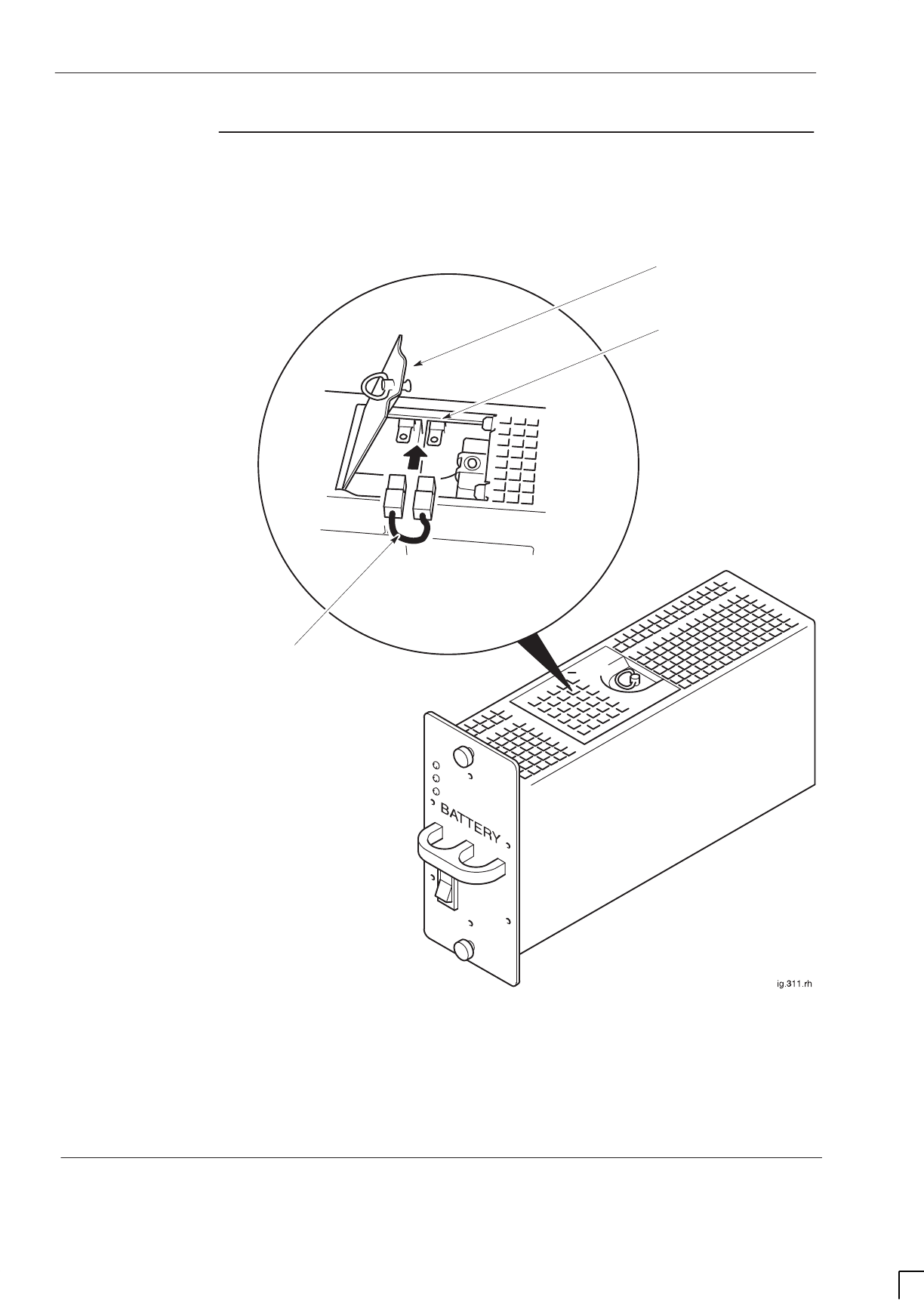
GSM-205-423
Installing a hold-up battery module
31st Oct 01
Inst. 2–62
Installation & Configuration: Horizon
macro
indoor
CONTROLLED INTRODUCTION
68P02902W08-B
Hold-up battery
module view
Figure 2-40 shows the hold-up battery module with the battery isolation jumper
connection shown in detail.
ACCESS HATCH
BATTERY SPADE
CONNECTORS
JUMPER LEAD
Figure 2-40 Connecting battery isolation jumper lead

31st Oct 01
Installation & Configuration: Horizon
macro
indoor
68P02902W08-B
CONTROLLED INTRODUCTION
i
Chapter 3
Interoperability between different
Motorola BTSs

GSM-205-423
31st Oct 01
ii
Installation & Configuration: Horizon
macro
indoor
CONTROLLED INTRODUCTION
68P02902W08-B

GSM-205-423
31st Oct 01
Installation & Configuration: Horizon
macro
indoor
68P02902W08-B
CONTROLLED INTRODUCTION
iii
Chapter 3
Interoperability between different Motorola BTSs i. . . . . . . . . . . . . . . .
Introduction to interoperability Inst. 3–1. . . . . . . . . . . . . . . . . . . . . . . . . . . . . . . . . . . . . . . . .
Mixed product sites Inst. 3–1. . . . . . . . . . . . . . . . . . . . . . . . . . . . . . . . . . . . . . . . . . . . .
Architectural constraints Inst. 3–1. . . . . . . . . . . . . . . . . . . . . . . . . . . . . . . . . . . . . . . . .
BTS architectures and interoperability Inst. 3–2. . . . . . . . . . . . . . . . . . . . . . . . . . . . . . . . . .
M-Cell6 and Horizonmacro architectures Inst. 3–2. . . . . . . . . . . . . . . . . . . . . . . . . . .
Example mixed site Inst. 3–3. . . . . . . . . . . . . . . . . . . . . . . . . . . . . . . . . . . . . . . . . . . . .
Technical issues Inst. 3–4. . . . . . . . . . . . . . . . . . . . . . . . . . . . . . . . . . . . . . . . . . . . . . . .
Receive path Inst. 3–4. . . . . . . . . . . . . . . . . . . . . . . . . . . . . . . . . . . . . . . . . . . . . . . . . . .
Transmit path Inst. 3–7. . . . . . . . . . . . . . . . . . . . . . . . . . . . . . . . . . . . . . . . . . . . . . . . . .
M-Cell6 and Horizonmacro hardware equivalents Inst. 3–10. . . . . . . . . . . . . . . . . . .
Further configuration information Inst. 3–10. . . . . . . . . . . . . . . . . . . . . . . . . . . . . . . . . .
Example configurations Inst. 3–11. . . . . . . . . . . . . . . . . . . . . . . . . . . . . . . . . . . . . . . . . .
Special hardware Inst. 3–14. . . . . . . . . . . . . . . . . . . . . . . . . . . . . . . . . . . . . . . . . . . . . . .

GSM-205-423
31st Oct 01
iv
Installation & Configuration: Horizon
macro
indoor
CONTROLLED INTRODUCTION
68P02902W08-B

GSM-205-423 Introduction to interoperability
31st Oct 01
Installation & Configuration: Horizon
macro
indoor
68P02902W08-B
CONTROLLED INTRODUCTION
Inst. 3–1
Introduction to interoperability
Mixed product
sites
This chapter describes how the Horizon
macro
indoor can be used in conjunction
with other Motorola BTS products.
Different Motorola product types can be collocated at the same physical site
without restriction, provided they are configured as logically separate
installations, and in accordance with the normal product engineering rules.
When mixed product types are installed at the same logical
site
,
a number of
technical issues arise that restrict the hardware that can be configured, and the
way it is interfaced. This chapter explains which product types can be mixed in
this way, and how they are interfaced.
NOTE This chapter only applies to the Horizon
macro
GSM/
EGSM900 and DCS1800 BTS variants.
GSM850 and PCS1900 Horizon
macro
BTS variants
cannot be mixed with other Motorola BTS types.
Architectural
constraints
To enable different product types to be used at the same logical site, one
product type is chosen as master
,
which is connected to the extender equipment
so that the two product types can function as a single, logical BTS. This
approach is viable when the product types to be interfaced have similar
architectures.
Motorola BTS product types that can be interfaced for collocation at a single
logical site are therefore restricted to those shown in Table 3-1 below.
Table 3-1 BTS compatibility for collocation at a single logical site
Master Extender
InCell M-Cell
2
M-Cell
6
Horizon
macro
InCell Discontinued No No No
M-Cell
2
No Yes* Yes* No
M-Cell
6
No No Yes* Yes
Horizon
macro
No No Yes* Yes
* Check for availability before ordering
Indoor and outdoor cabinets can be mixed, but different mechanical
arrangements may be required for routeing the inter-cabinet cabling.
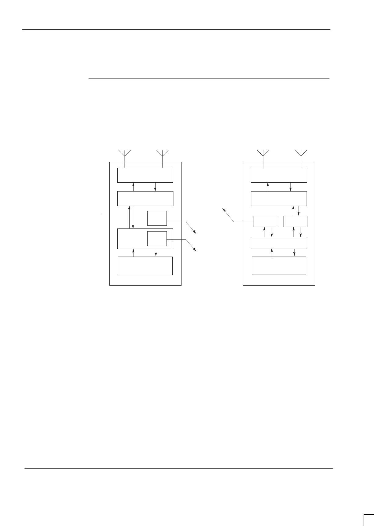
GSM-205-423
BTS architectures and interoperability
31st Oct 01
Inst. 3–2
Installation & Configuration: Horizon
macro
indoor
CONTROLLED INTRODUCTION
68P02902W08-B
BTS architectures and interoperability
M-Cell
6
and
Horizon
macro
architectures
Figure 3-1 represents the high level architecture of the M-Cell
6
and
Horizon
macro
BTSs. Both systems provide an optical interface for connection to
remote transceivers, which in a normal installation would be used to connect to
transceivers of the same product type.
CTU
RF coupling
MCUF FMUX
Network termination
functions
FMUX
Horizon
macro
M-Cell
6
Fibre optic links
to remote radios
TCU
RF coupling
MCU
FMUX
Network termination
functions
FOX
Figure 3-1 High level architecture of M-Cell
6
and Horizon
macro
BTSs
However, since the optical interface is identical for both products, it can be used
to link an M-Cell
6
to Horizon
macro
transceivers, or a Horizon
macro
to M-Cell
6
transceivers. The principle is shown in Figure 3-2.
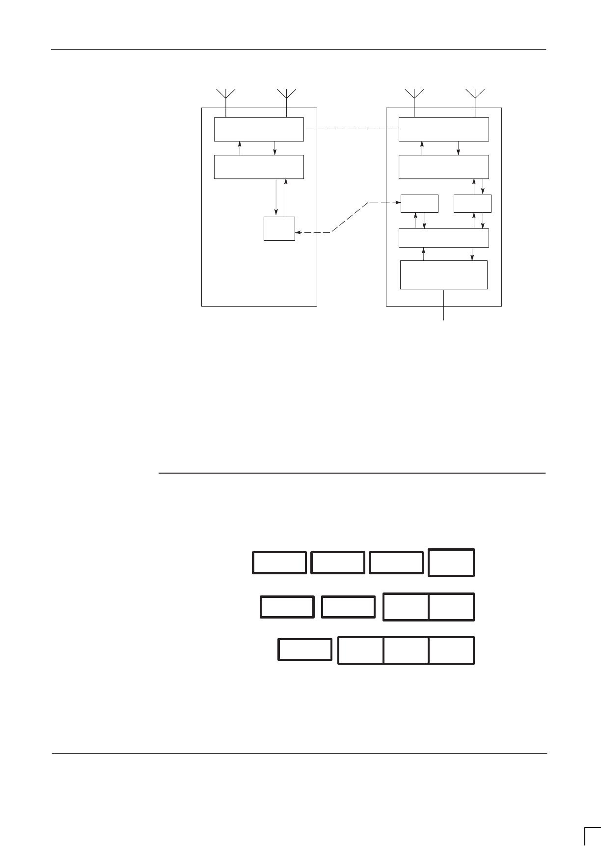
GSM-205-423 BTS architectures and interoperability
31st Oct 01
Installation & Configuration: Horizon
macro
indoor
68P02902W08-B
CONTROLLED INTRODUCTION
Inst. 3–3
CTU
Horizon
macro
(Extender)
RF coupling
FMUX
Fibre optic link
TCU
RF coupling
MCU
FMUX
Network termination
functions
Cross connections
(see text)
Abis Interface
FOX
M-Cell
6
(Master)
Figure 3-2 Example of interfacing different products at a single logical site
When two product types are interfaced in this way, the control function for the
entire BTS is implemented by the master product. In Figure 3-2, this is the
M-Cell
6
. In practice, either BTS can be configured as master according to the
needs of the network concerned.
Example mixed
site
A multi-cabinet mixed site can typically be achieved in several ways. Figure 3-3
shows the alternatives layouts for a four cabinet mixed BTS site
M-Cell
6
M-Cell
6
M-Cell
6
M-Cell
6
M-Cell
6
M-Cell
6
Layout1
Layout3
Layout2 Horizon
macro
Horizon
macro
Horizon
macro
Horizon
macro
Horizon
macro
Horizon
macro
Figure 3-3 Example of alternative layouts for a 4-cabinet mixed BTS site

GSM-205-423
BTS architectures and interoperability
31st Oct 01
Inst. 3–4
Installation & Configuration: Horizon
macro
indoor
CONTROLLED INTRODUCTION
68P02902W08-B
Technical
issues
When mixing different BTS types, the interface may be required to resolve
some or all of the following issues, depending on the site configuration:
SThe interface must deliver both Rx and Rxdiv (receive diversity) signals to
each transceiver.
SThe interface must not change the uplink (receive) signal level delivered to
any transceiver.
SThe interface must ensure that in the mixed BTS configuration, RF
combiners remain correctly loaded.
Receive path
When a cell is wholly configured within one cabinet, there is no requirement to
connect the uplink or downlink RF signals between the master and extender
cabinets. The only interface between the cabinets in this type of mixed BTS
configuration is therefore at digital level, between FMUXs via the fibre optic link.
When a cell is split between two cabinets, the uplink signals must be connected
between the cabinets since both Rx and Rxdiv signals are required at each
transceiver. In this situation the downlink signal may or may not require
connection between cabinets, depending on the site configuration. The uplink
connectivity requirements are shown in Figure 3-4 (DCS1800) and Figure 3-5
(GSM900).
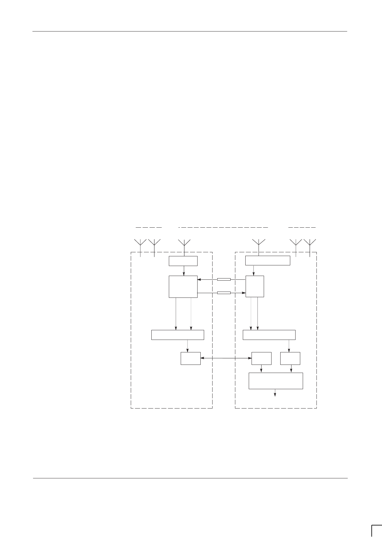
GSM-205-423 BTS architectures and interoperability
31st Oct 01
Installation & Configuration: Horizon
macro
indoor
68P02902W08-B
CONTROLLED INTRODUCTION
Inst. 3–5
DCS1800
Refer to Figure 3-4. In the Horizon
macro
cabinet, low noise amplification in the
SURF module first boosts the Rx signal by +13 dB. Separate Rx outputs from
the SURF are then discretely routed to relevant transceivers in the master
cabinet, and to the LNA in the extender cabinet. Since the LNA boosts the Rx
signal by a further +13 dB, a 13 dB attenuator is placed in the signal path to
offset this additional signal gain, which would otherwise result in signal levels
outside the permitted range for the transceivers.
The Rxdiv signal is similarly given a +13 dB boost by the LNA in the extender
cabinet. Separate Rxdiv outputs from the LNA are then discretely routed to
relevant receivers in the extender cabinet, and to the SURF module in the
master cabinet. Since the SURF provides a further +13 dB boost, a 13 dB
attenuator is again placed in the signal path to offset this additional gain.
In this way, the arrangement shown in Figure 3-4 delivers Rx and Rxdiv signals
to the uplink path in both cabinets, at the required signal level.
To NIU and Abis
Interface
Rx
Rxdiv
M-Cell
6
(Master)
CTU
Cell A Cell B Cell C
Rxdiv
Rx Rx Rxdiv
Duplexer
SURF +13 dB
–13 dB
+13 dB
Rxdiv
Rx
LNA
Rx Rxdiv
–13 dB
TCU
Horizon
macro
(Extender)
Rxdiv
Rx
FMUX
MCU
FMUX
Fibre
optic
link
Duplexer
FOX
Figure 3-4 Functional overview of the receive path for a DCS1800 split cell
configuration
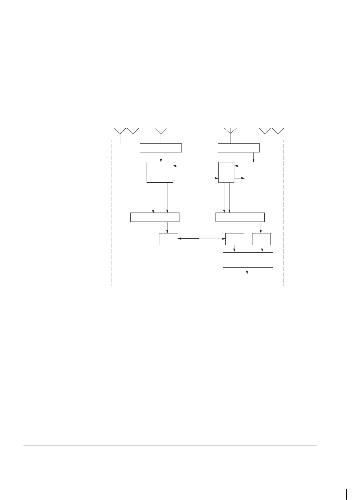
GSM-205-423
BTS architectures and interoperability
31st Oct 01
Inst. 3–6
Installation & Configuration: Horizon
macro
indoor
CONTROLLED INTRODUCTION
68P02902W08-B
GSM900
Refer to Figure 3-5. In GSM900 products, RF gain for the IADU and SURF is
configurable. A split cell configuration is therefore dealt with in the same way as
that described for DCS1800, except that the 13 dB attennuators are not
required. Instead, the required signal level is maintained by using appropriate
gain settings for the IADU and SURF.
CTU
Cell A Cell B Cell C
Rxdiv
Rx Rx Rxdiv
Duplexer
IADU
*
SURF
*
Rxdiv
Rx
DLNB
Rx Rxdiv
TCU
Rx
Rxdiv
Rxdiv
Rx
* Configurable gain
Duplexer
To NIU and Abis
Interface
M-Cell
6
(Master)Horizon
macro
(Extender)
FMUX
MCU
FMUX
Fibre
optic
link
FOX
Figure 3-5 Functional overview of the receive path for a GSM900 split cell
configuration
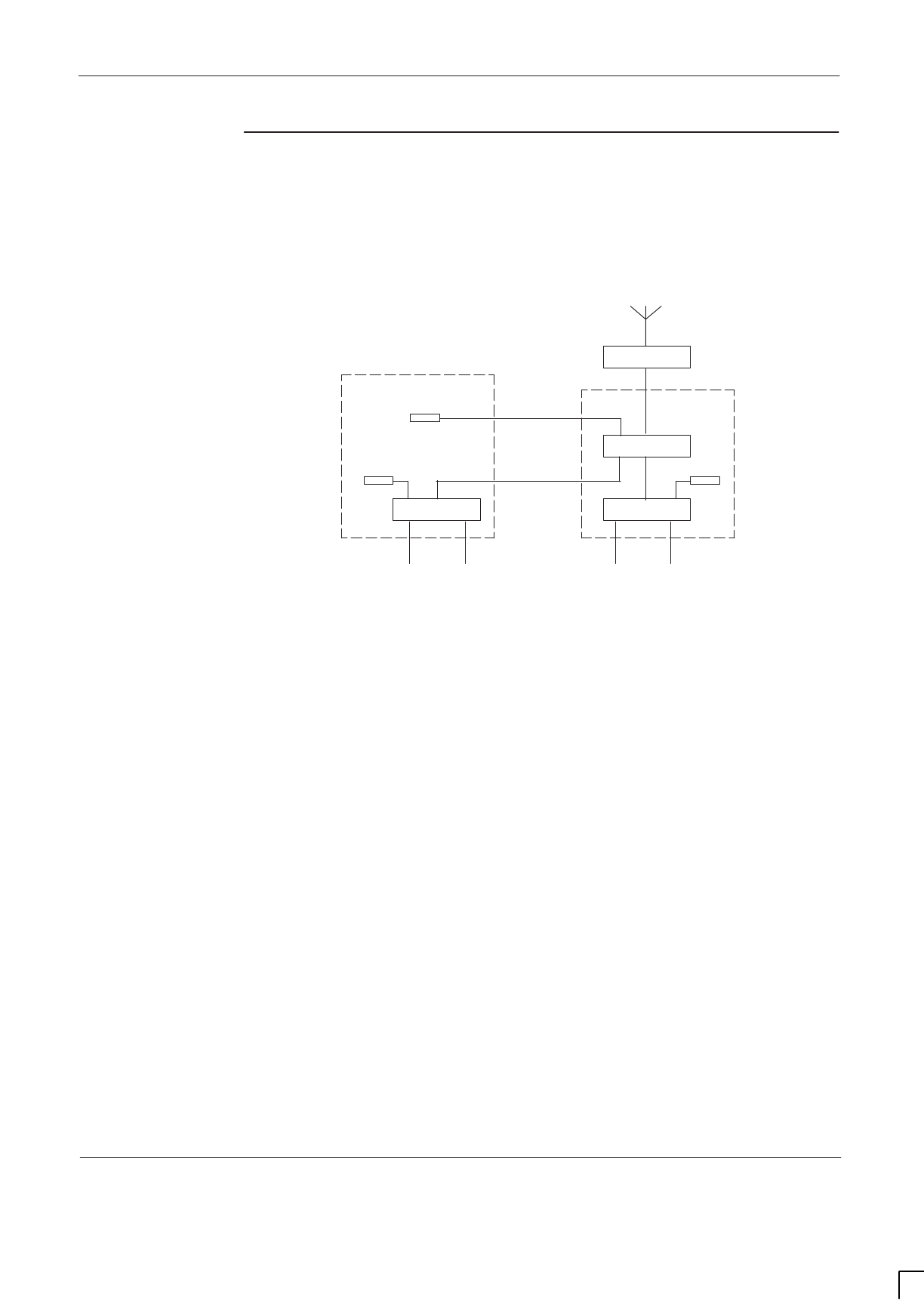
GSM-205-423 BTS architectures and interoperability
31st Oct 01
Installation & Configuration: Horizon
macro
indoor
68P02902W08-B
CONTROLLED INTRODUCTION
Inst. 3–7
Transmit path
M-Cell
6
combining
When configuring the downlink paths for a cell using three carriers or more, it
may be necessary to provide additional external RF load(s) for the combiners.
This is illustrated by Figure 3-6, which shows a typical M-Cell
6
combining
arrangement for a 4-carrier cell.
Hybrid
HybridHybrid
Duplexer
Load
Load
3IP CBF
HCOMB
External
load
One carrier from each of four transceivers
Carrier 1 Carrier 2 Carrier 3 Carrier 4
Figure 3-6 Typical M-Cell
6
arrangement for combining four carriers
Carriers 1 and 2 are combined in a hybrid combiner (HCOMB) module. The
output from this module provides one of the three inputs to the 3IP CBF. The
HCOMB is equipped with an internal RF load, and is therefore self–contained.
The 3IP CBF requires one RF load for each of the two hybrids it contains, but is
equipped with only a single internal RF load. An additional load is therefore
provided for this purpose on the HCOMB casing.
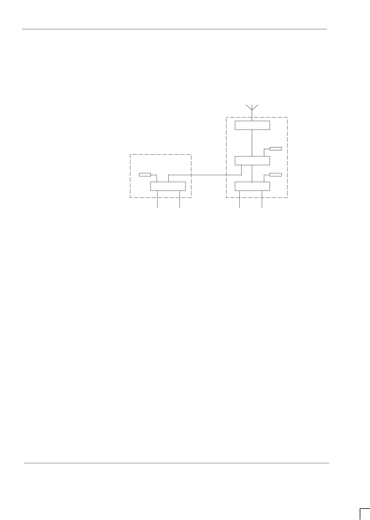
GSM-205-423
BTS architectures and interoperability
31st Oct 01
Inst. 3–8
Installation & Configuration: Horizon
macro
indoor
CONTROLLED INTRODUCTION
68P02902W08-B
Horizon
macro
combining
A similar arrangement is used in the Horizon
macro
, which uses a Hybrid
Combiner Unit (HCU) and Dual stage Duplexed combining Filter (DDF), as
shown in Figure 3-7. The DDF has three input ports together with two internal
RF loads, and therefore does not require the addition of any external load.
Hybrid
HybridHybrid
Duplexer
Load
Load
DDF
HCU
One carrier from each of four transceivers
Carrier 1 Carrier 2 Carrier 3 Carrier 4
Load
Figure 3-7 Typical Horizon
macro
arrangement for combining four carriers
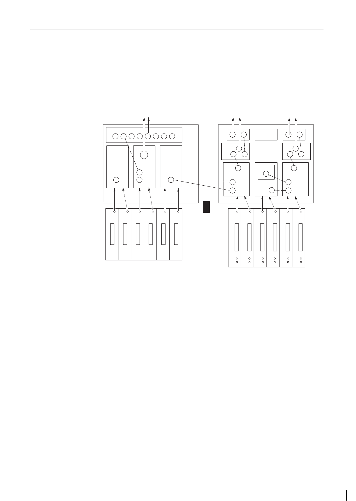
GSM-205-423 BTS architectures and interoperability
31st Oct 01
Installation & Configuration: Horizon
macro
indoor
68P02902W08-B
CONTROLLED INTRODUCTION
Inst. 3–9
Mixed equipment combining
When the two different product types are interfaced, a situation can arise where
a 3IP CBF is connected to an HCU, as shown in Figure 3-8. In this configuration
it is therefore necessary to provide an additional external RF load for this 3IP
CBF. The example in Figure 3-8 shows downlink connections for a 4/4/4
configuration using mixed BTS types.
3IP CBF 2
Load
Load
HCOMB
HCU 2 DDF HCU 1
543 21011109876
2B 1B 0B 2A 1A 0A B A
Sector3 Sector2 Sector1
M-Cell
6
Horizon
macro
3IP CBF 1
Figure 3-8 Downlink configuration for a 4/4/4 mixed cabinet installation
Inputs for the DDF are carriers 8 and 9, together with the output of HCU2. The
DDF contains two RF loads and is therefore self-contained. Inputs to 3IP CBF1
are carriers 0 and 1, together with the combined output of HCOMB. 3IP CBF1
contains a single load and is therefore connected to the external load mounted
on HCOMB. Inputs for 3IP CBF2 are carriers 4 and 5, together with the output
of HCU1, from the master cabinet. 3IP CBF2 contains a single load and
therefore requires the addition of an external 50 ohm load, as shown.

GSM-205-423
BTS architectures and interoperability
31st Oct 01
Inst. 3–10
Installation & Configuration: Horizon
macro
indoor
CONTROLLED INTRODUCTION
68P02902W08-B
M-Cell
6
and
Horizon
macro
hardware
equivalents
Table 3-2 shows the RF hardware equivalents for the Horizon
macro
and M-Cell
6
BTSs.
Table 3-2 RF hardware equivalents for Horizon
macro
/M-Cell
6
Horizon
macro
900/1800 M-Cell 900 M-Cell 1800
DCF CBF + duplexer Hybrid + duplexer
DDF 3- input CBF* +
duplexer 2 x hybrid + dup/BPF
HCU Hybrid Hybrid
Feedthrough plate Non-hybrid (no equivalent)
TDF TBF + duplexer 2 x dup/BPF
CCB master CCB master CCB master
CCB extender CCB extender CCB extender
SURF 3 x DLNB + IADU 3 x LNA
Split Sector Cable Rx Extender (no equivalent)
* 3-input CBF contains only one internal 50 ohm load.
Further
configuration
information
Provided the functional guidelines described in this chapter are followed, the
steps involved in upgrading an existing site with mixed equipment are
essentially the same as with a conventional upgrade:
SDetermine the number of additional carriers required in the upgraded site.
SBased on the required site configuration (for example, 4/4/4), use the
functional guidelines provided in this chapter to decide the most effective
hardware configuration for the additional cabinet(s).
SSpecial upgrade kits are available for specified configurations.
SConfiguration diagrams and product ordering help are available from the
Motorola local office.
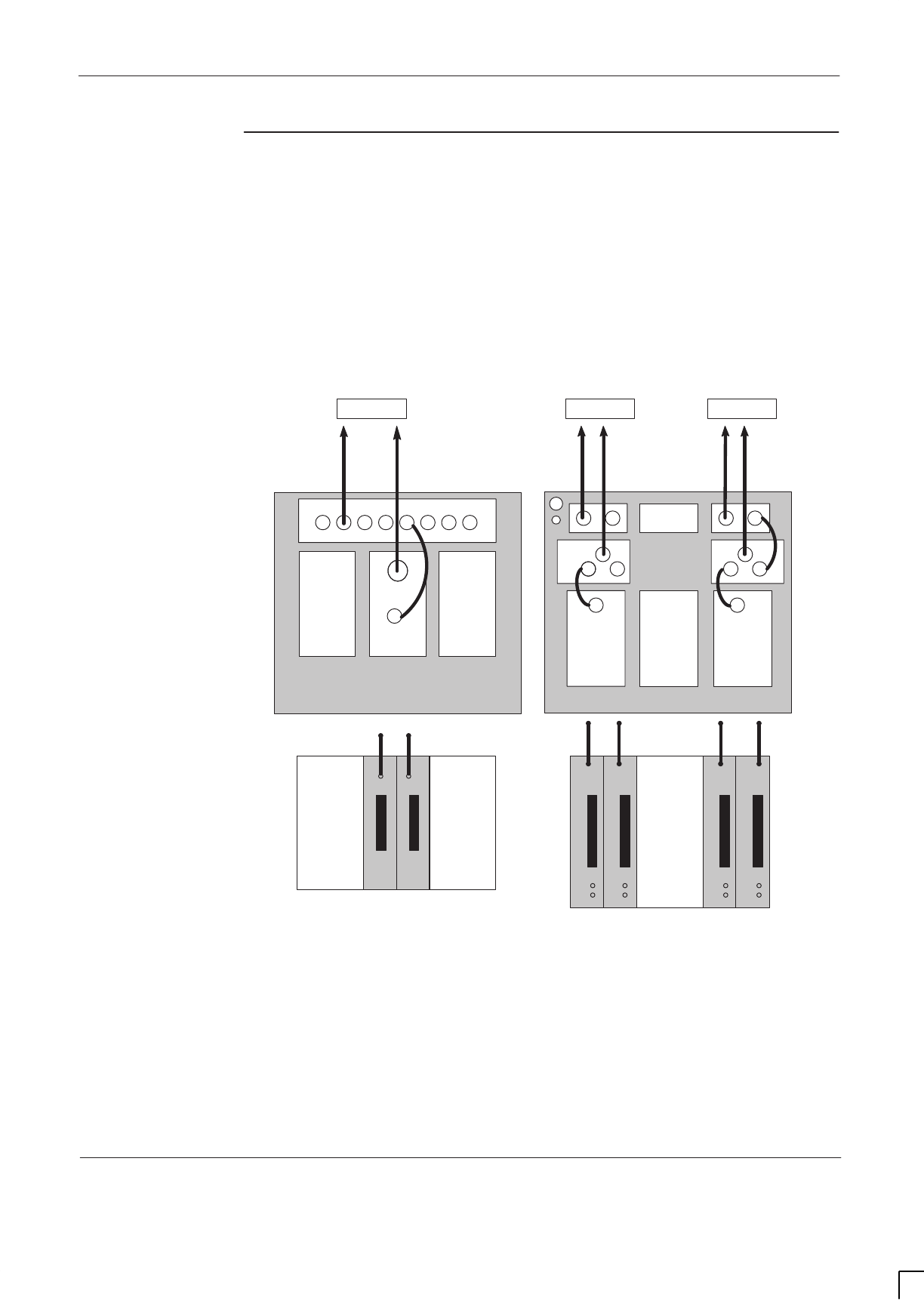
GSM-205-423 BTS architectures and interoperability
31st Oct 01
Installation & Configuration: Horizon
macro
indoor
68P02902W08-B
CONTROLLED INTRODUCTION
Inst. 3–11
Example
configurations
Configuration diagrams provided by the Motorola local office show top of rack
cable and antenna connections for mixed product configurations, together with
details of external RF loads required. Figure 3-9, Figure 3-10 and Figure 3-11
are examples of the type of diagram that can be provided.
GSM900 2/2/2 configuration using two cabinets
In this configuration, there are no split cells, and therefore no uplink/downlink
connections between the cabinets. The CBFs are 2-input devices, consequently
no external RF loads are required.
Sector 2
2B 1B 0B 2A 1A 0A B A
BLANK BLANKDCF CBF BLANK CBF
EXT
Sector 3 Sector 1
Horizon
macro
M-Cell
6
Figure 3-9 GSM900 mixed Horizon
macro
/ M-Cell
6
2/2/2 configuration using
two cabinets
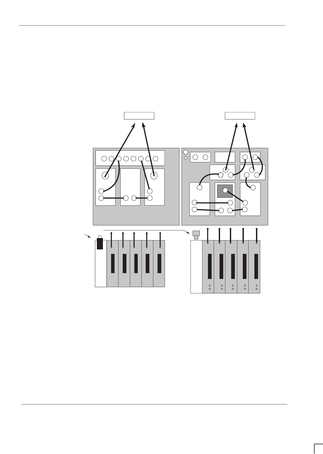
GSM-205-423
BTS architectures and interoperability
31st Oct 01
Inst. 3–12
Installation & Configuration: Horizon
macro
indoor
CONTROLLED INTRODUCTION
68P02902W08-B
GSM900 5/5 configuration using two cabinets
In this configuration, there are no split cells, and therefore no uplink or downlink
connections between the cabinets. In the M-Cell
6
cabinet, both 3IP CBFs are
configured with external loads provided by the NON HYB. In the Horizon
macro,
one DDF has two direct RF inputs, plus a third input via the FEEDTHRU. The
second DDF has two RF inputs, one direct and one via the FEEDTHRU. This
arrangement facilitates using the transceivers in sequence. The two 50 ohm
loads are required to terminate the unused DDF/3IP CBF input ports.
2B 1B 0B 2A 1A 0A B A
DDF2 DDF1FEEDTHRU 3IP CBF2 NON-HYB 3IP CBF1
EXT
50 ohm loads
Sector 1Sector 2
Horizon
macro
M-Cell
6
Figure 3-10 GSM900 mixed Horizon
macro
/ M-Cell
6
5/5 configuration using
two cabinets
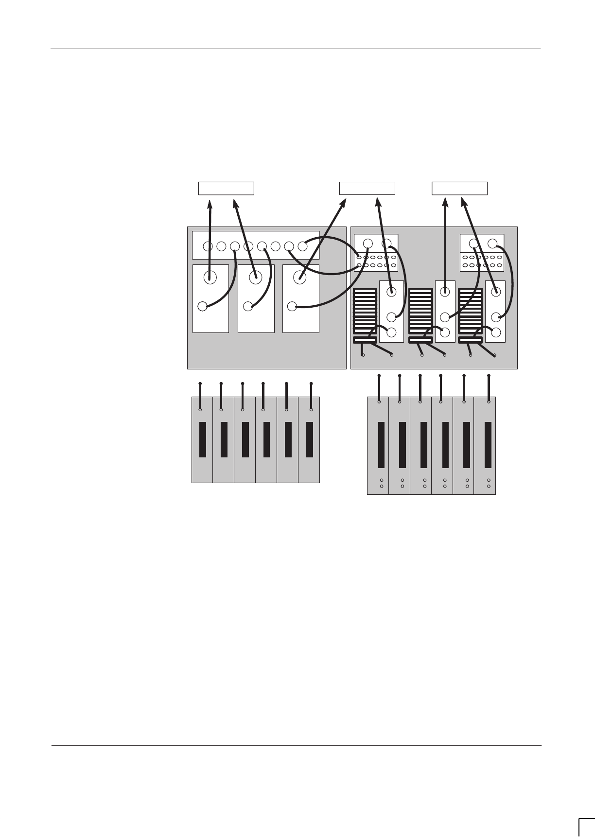
GSM-205-423 BTS architectures and interoperability
31st Oct 01
Installation & Configuration: Horizon
macro
indoor
68P02902W08-B
CONTROLLED INTRODUCTION
Inst. 3–13
DCS1800 4/4/4 configuration using two cabinets
In this configuration, sector 2 is split between the cabinets. The uplink Rx and
Rxdiv signals for sector 2 are therefore connected between the BTS types to
ensure the availability of both signals in both cabinets. In the M-Cell
6
cabinet,
2-input hybrids are used for combining, each configured with a discrete external
load.
2B 1B 0B 2A 1A 0A B A
DCF HYB
EXT
DCF DCF DUP DUP DUPHYB HYB
Sector 2Sector 3 Sector 1
Horizon
macro
M-Cell
6
Figure 3-11 DCS1800 Mixed Horizon
macro
/ M-Cell
6
4/4/4 configuration using
two cabinets
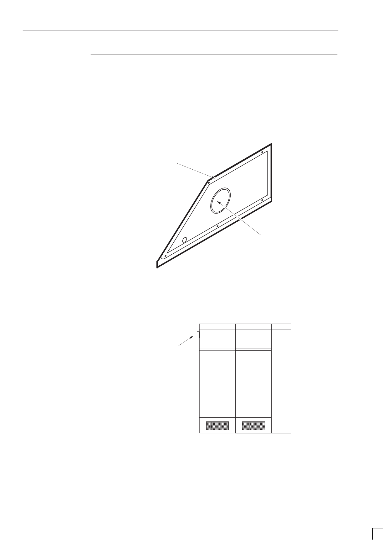
GSM-205-423
BTS architectures and interoperability
31st Oct 01
Inst. 3–14
Installation & Configuration: Horizon
macro
indoor
CONTROLLED INTRODUCTION
68P02902W08-B
Special
hardware
A range of cables is available for uplink, downlink and fibre optic connections,
together with the uplink attennuators described earlier. Contact the Motorola
local office for further details.
In addition, the mounting plate and snap-in multi cable gland shown in
Figure 3-12 are required when expanding M-Cell
6
outdoor sites with
Horizonmacro cabinets. In this type of configuration, the Horizon
macro
equipment is located to the left of the M-Cell
6
cabinets.
CABLE GLAND ENTRY
PORT ACCEPTS SNAP-IN
MULTI CABLE GLAND
ENVIRONMENTAL
GASKET
Figure 3-12 Special cable gland plate required for mixed M-Cell
6
and
Horizon
macro
installations
The mounting plate is located as shown in Figure 3-13 in place of the original
blanking plate fitted to the M-Cell
6
.
MULTI CABLE
GLAND
M-Cell
6
CABINETS
Figure 3-13 Location of the snap-in multi cable gland and mounting plate in the
M-Cell
6

31st Oct 01
Installation & Configuration: Horizon
macro
indoor
68P02902W08-B
CONTROLLED INTRODUCTION
i
Chapter 4
Commissioning of indoor cabinet

GSM-205-423
31st Oct 01
ii
Installation & Configuration: Horizon
macro
indoor
CONTROLLED INTRODUCTION
68P02902W08-B

GSM-205-423
31st Oct 01
Installation & Configuration: Horizon
macro
indoor
68P02902W08-B
CONTROLLED INTRODUCTION
iii
Chapter 4
Commissioning of indoor cabinet i. . . . . . . . . . . . . . . . . . . . . . . . . . . . . .
Commissioning overview and test equipment Inst. 4–1. . . . . . . . . . . . . . . . . . . . . . . . . . . .
Overview of commissioning Inst. 4–1. . . . . . . . . . . . . . . . . . . . . . . . . . . . . . . . . . . . . .
PC to MCUF cable pin connections Inst. 4–1. . . . . . . . . . . . . . . . . . . . . . . . . . . . . . .
Test equipment Inst. 4–2. . . . . . . . . . . . . . . . . . . . . . . . . . . . . . . . . . . . . . . . . . . . . . . . .
Pre-power up checks Inst. 4–3. . . . . . . . . . . . . . . . . . . . . . . . . . . . . . . . . . . . . . . . . . . . . . . . .
Overview of pre-power up checks Inst. 4–3. . . . . . . . . . . . . . . . . . . . . . . . . . . . . . . . .
Visual inspection Inst. 4–4. . . . . . . . . . . . . . . . . . . . . . . . . . . . . . . . . . . . . . . . . . . . . . . .
Request for power supply connection Inst. 4–4. . . . . . . . . . . . . . . . . . . . . . . . . . . . . .
Earth continuity check Inst. 4–5. . . . . . . . . . . . . . . . . . . . . . . . . . . . . . . . . . . . . . . . . . .
AC power system insulation check Inst. 4–5. . . . . . . . . . . . . . . . . . . . . . . . . . . . . . . .
Powering up the cabinet Inst. 4–6. . . . . . . . . . . . . . . . . . . . . . . . . . . . . . . . . . . . . . . . . . . . . .
Power up overview Inst. 4–6. . . . . . . . . . . . . . . . . . . . . . . . . . . . . . . . . . . . . . . . . . . . . .
Power up procedure without code load Inst. 4–6. . . . . . . . . . . . . . . . . . . . . . . . . . . .
Power down of cabinet Inst. 4–7. . . . . . . . . . . . . . . . . . . . . . . . . . . . . . . . . . . . . . . . . .
Power up procedure with code load Inst. 4–7. . . . . . . . . . . . . . . . . . . . . . . . . . . . . . .
Installation and configuration Inst. 4–9. . . . . . . . . . . . . . . . . . . . . . . . . . . . . . . . . . . . .
Cabinet and CBM views Inst. 4–10. . . . . . . . . . . . . . . . . . . . . . . . . . . . . . . . . . . . . . . . .
Sample form 1: Request for connection Inst. 4–11. . . . . . . . . . . . . . . . . . . . . . . . . . . . . . . . .
Sample form 2: Completion and inspection form Inst. 4–13. . . . . . . . . . . . . . . . . . . . . . . . .

GSM-205-423
31st Oct 01
iv
Installation & Configuration: Horizon
macro
indoor
CONTROLLED INTRODUCTION
68P02902W08-B
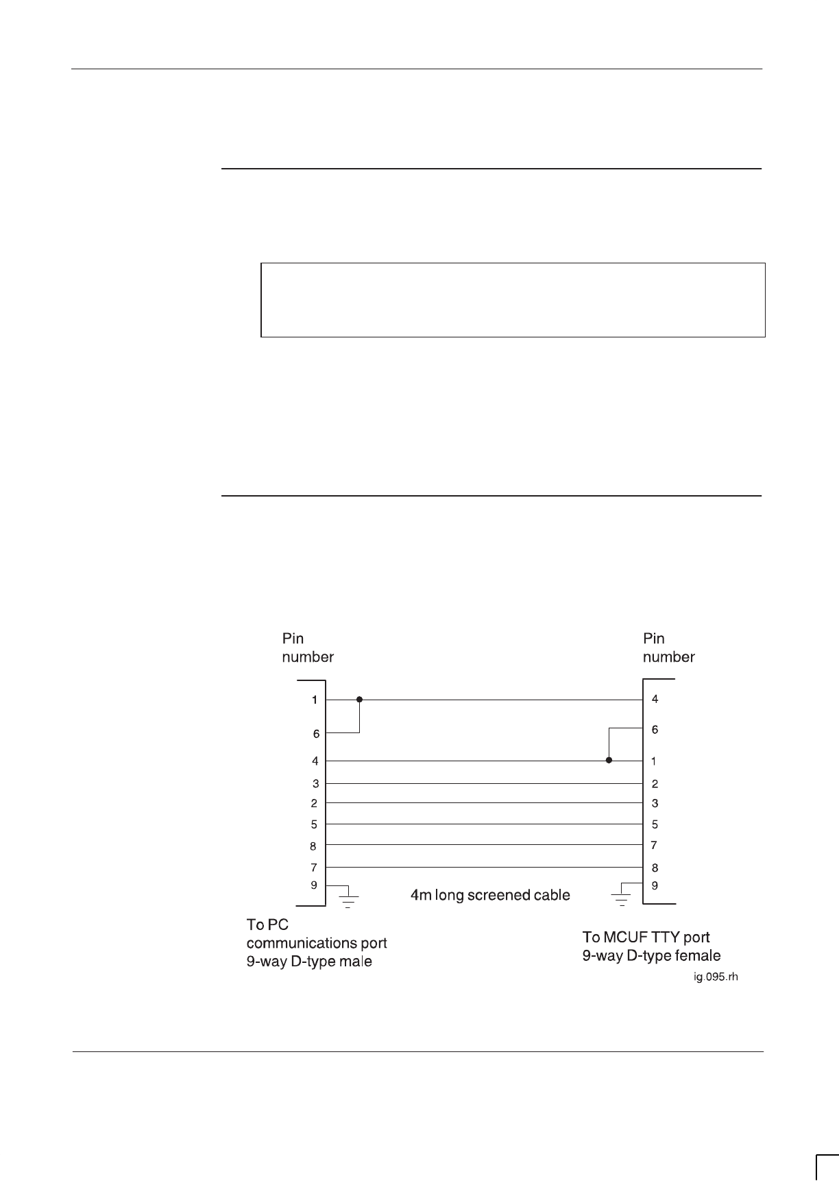
GSM-205-423 Commissioning overview and test equipment
31st Oct 01
Installation & Configuration: Horizon
macro
indoor
68P02902W08-B
CONTROLLED INTRODUCTION
Inst. 4–1
Commissioning overview and test equipment
Overview of
commissioning
This chapter provides information required for the commissioning of cabinets
and their internal and external interfaces.
NOTE Some equipment at the site may not be produced by
Motorola, including battery chargers, power supplies, and
antennas. Refer to site-specific documentation and the
non-Motorola vendor instructions.
All site preparation and equipment installation in the previous chapters must be
completed before commissioning. Commissioning consists of the following:
SPre-power up checks.
SPowering up the cabinet.
SOptimization procedures as detailed in
Installation and Configuration: BSS
Optimization (GSM-100-423)
.
PC to MCUF
cable pin
connections
Figure 4-1 shows the pin connections for the PC to MCUF test cable. These are
standard null modem pin connections. There is also a TTY adapter, to attach to
the cable, for CTU use, Motorola part number 58C86540N01.
Figure 4-1 9-way to 9-way PC to MCUF cable pin connections

GSM-205-423
Commissioning overview and test equipment
31st Oct 01
Inst. 4–2
Installation & Configuration: Horizon
macro
indoor
CONTROLLED INTRODUCTION
68P02902W08-B
Test equipment
Table 4-1 provides details of the test equipment required to perform the
commissioning procedures in this chapter.
Table 4-1 Test equipment required for commissioning
Quantity Description Comments
1IBM compatible portable
Personal Computer (PC) (486
DX2 or DX4 minimum)
The minimum requirements are:
TFT colour screen.
170 Mbyte hard drive
(minimum).
Minimum 4 Mbyte RAM or
recommended 8 Mbyte.
3.5 inch floppy drive.
Serial port.
CD-ROM drive (recommended)
PCMCIA (Type 2) compatible
slot.
Windows (3.1 running in 386
enhanced mode minimum)
loaded and running.
Battery power.
1Commercial terminal emulator
software PC PLUS or similar software
(suitable for PC being used)
1Digital multimeter (must be
sensitive enough to measure
0.05 ohms)
Hewlett Packard E2378A or
equivalent
1ESD protection kit
19-way male D-type to 9-way
female D-type adaptor For PC to MCUF
Pin connections shown in
Figure 4-1.
1PAT tester Insulation and earth tester

GSM-205-423 Pre-power up checks
31st Oct 01
Installation & Configuration: Horizon
macro
indoor
68P02902W08-B
CONTROLLED INTRODUCTION
Inst. 4–3
Pre-power up checks
Overview of
pre-power up
checks
WARNING Before powering up the equipment, the power system
checks provided in this section must be performed.
This section contains procedures for testing the power system prior to applying
power to the cabinet.
WARNING 230 V is present within the cabinet, when the cabinet is
directly connected to an ac supply.
Earth straps are not to be worn during the commissioning
of the ac and dc power system, and watches and other
jewellery should be removed.
Only insulated tools should be used.
CAUTION This equipment contains CMOS devices and is vulnerable
to static discharge. Although the damage may not be
immediately apparent, CMOS devices may be damaged in
the long term due to mishandling causing barrier
breakdown.
The approved earth strap (high impedance) must be worn
at all times when adjusting or handling the processor
cards (but see WARNING above, regarding use of earth
straps).
If the cabinet door is kept open for long periods of time
during commissioning, an alternative method of cooling
must be provided to avoid damage to the equipment
through overheating.

GSM-205-423
Pre-power up checks
31st Oct 01
Inst. 4–4
Installation & Configuration: Horizon
macro
indoor
CONTROLLED INTRODUCTION
68P02902W08-B
Visual
inspection
Inspect the installation for damage in accordance with BS 7671 (16th Edition
<Section 712>) or the IEC 364 equivalent.
WARNING If damage is discovered during the visual inspection, the
commissioning must not proceed further until the damage
has been inspected and rectified by the manufacturers or
their representatives.
Cabinet exterior
Examine the exterior of the cabinets for structural, paint or mechanical damage
and report any damage to Motorola.
Cabinet interior
Examine the interior of the cabinet for structural, paint or mechanical damage
and report any damage to Motorola.
Power equipment
Examine the power equipment for mechanical damage and report any damage
to Motorola.
Request for
power supply
connection
Ensure that all correct Request for connection and Completion and
inspection form certificates have been sent to the local electricity supplier.
NOTE Samples of a typical Request for connection and a
Completion and inspection form are shown in Sample
form 1 and Sample form 2 at the end of this chapter.

GSM-205-423 Pre-power up checks
31st Oct 01
Installation & Configuration: Horizon
macro
indoor
68P02902W08-B
CONTROLLED INTRODUCTION
Inst. 4–5
Earth continuity
check
Ensure an earth continuity check has been performed on appropriate equipment
if required. Use the digital multimeter to check that the resistance of the test
equipment leads is less than 0.05 ohms.
Main equipment earths
Connect the PAT tester to the earth terminal and to the following earth points:
SAntenna feeders.
SAC supply input earth.
– The local electricity board termination point.
– AC distribution board.
– AC supply isolator.
NOTE The switched isolator will not be connected to earth if it is
a double insulated device and will therefore not require
testing.
SBattery box chassis.
SCabinet chassis (all cabinets).
S+27 V power supply unit chassis.
SRack members.
Check that the measured resistance is less than 0.1 ohms with the tester
connected to a conductive surface (bare metal) at extreme ends of the earth
cables.
On completion of each earth check apply conductive non-oxidizing grease to the
earth connections on the earth busbar.
AC power
system
insulation
check
Ensure an insulation check has been performed on all ac power cables which
supply the site up to the ac input to the Cabinet. Testing must be carried out in
accordance with the BS 7671 (16th Edition <section 713-04–01 to 713-04-06>)
or IEC 364 equivalent, at the voltage levels shown in Table 4-2, using an
approved insulation tester. Check that the resistance at each point is as shown
in Table 4-2.
Table 4-2 BS7671 (16th edition) Table 71A (part of)
Parameter AC test voltage
(volts) Minimum insulation
(megohms)
Up to and including 500 V 500 0.5
When the test has been completed, sign the completion and inspection
certificate, a sample of which may be found in Sample form 2.

GSM-205-423
Powering up the cabinet
31st Oct 01
Inst. 4–6
Installation & Configuration: Horizon
macro
indoor
CONTROLLED INTRODUCTION
68P02902W08-B
Powering up the cabinet
Power up
overview
This procedure assumes all previous procedures have been completed.
CAUTION Ensure correct PSMs are fitted to match the supply source
voltage.
Ensure that there is no blockage to ventilation at the base
of the cabinet.
Power up
procedure
without code
load
The following procedure should be carried out to power up the cabinet, with no
code load. This proves the cabinet hardware is capable of operation. The
procedure for cabinet code load is described in the next section.
Relevant components are shown in Figure 4-2.
WARNING Earth straps are not to be worn during the commissioning
of the power system, and watches and other jewellery
should be removed.
Only insulated tools should be used.
The power source must be supplied to the cabinet via a
suitable over-current protective device and be isolated
from the BTS cabinet.
Procedure to prepare cabinet for power up without code load
To prepare the cabinet prior to power up:
1. Ensure the power source isolator is switched off.
2. Disconnect all E1/T1 lines from the BTS.
3. If fitted, remove the optional PCMCIA card from the MCUF slot.
4. Set the switch of each PSM to the OUTPUT DISABLE position.
5. Press and release all push on/push off circuit breaker buttons to the out
(off) position.

GSM-205-423 Powering up the cabinet
31st Oct 01
Installation & Configuration: Horizon
macro
indoor
68P02902W08-B
CONTROLLED INTRODUCTION
Inst. 4–7
Power up of cabinet without code load
To power up the cabinet:
1. Switch on the external power supply to the cabinet.
2. Turn each PSM switch to the OUTPUT ENABLE position; check that each
PSM has the active (green) LED on and the alarm (red) LED off.
3. Press the CBM circuit breaker button marked FANS. Check that each fan
module is operating correctly. Activate any fan not started by the restart
button (marked either FRONT or REAR) on the fan module.
4. Press the CBM circuit breaker button marked SURF, and if CCBs are
fitted, press the circuit breaker buttons marked CCB0 and CCB1.
5. Press the CBM circuit breaker button marked BPSM A and (if redundant
BPSM fitted) BPSM B. Check all associated digital module LEDs operate
correctly; green LEDs lit on BPSM, NIU and MCUF, and red LEDs off on
NIU and MCUF.
NOTE Both red and green LEDs are initially lit on the NIU while
the unit conducts a self test. After approximately 20
seconds, the red LED will extinguish, indicating normal
condition.
6. Press the appropriate CBM circuit breaker buttons for the CTUs fitted, and
check that the RADIO STATUS LED for each CTU flashes green.
7. Close the door to ensure correct ventilation.
This completes the power up of the cabinet.
Power down of
cabinet
If the cabinet is not required to remain powered up, power down the cabinet as
follows:
1. Press all circuit breaker buttons to the out (off) position.
2. Switch each PSM to the OUTPUT DISABLE position.
3. Switch off the external power supply to the cabinet.
This completes the power down of the cabinet.
Power up
procedure with
code load
The following procedure should be carried out to power up the cabinet, with
code load. The code will be provided either direct from the BSC from E1 line or
from a PCMCIA card installed in the PCMCIA socket of the master MCUF.
Relevant components are shown in Figure 4-2.
CAUTION This procedure should be carried out only by experienced
field engineers.

GSM-205-423
Powering up the cabinet
31st Oct 01
Inst. 4–8
Installation & Configuration: Horizon
macro
indoor
CONTROLLED INTRODUCTION
68P02902W08-B
Procedure to prepare cabinet for power up with code load
To prepare the cabinet prior to power up, proceed as follows:
1. Ensure E1 connection to BSC is made.
2. Insert (optional) PCMCIA card in MCUF PCMCIA socket.
3. Connect the 9 to 9-way cable from the PC serial A port to MCUF TTY port.
4. At the PC start the terminal emulator program.
5. Change to Level 3 and at the MMI-RAM> prompt type:
CTRL N
6. Set the switch of each PSM to the OUTPUT DISABLE position.
7. Press and release all push on/push off circuit breaker buttons to the out
(off) position.
Power up of cabinet with code load
To power up the cabinet, proceed as follows:
CAUTION When the two LEDs of the CTU or the MCUF are flashing,
the boot code is downloading into non-volatile memory for
software upgrade. Power should not be removed, nor the
cabinet reset, until downloading has been completed, as
this will corrupt the non-volatile memory. If boot code is
corrupted, contact the Motorola Customer Network
Resolution Centre and request the boot code restoration
procedure and the appropriate boot code file.
1. Switch on the external power supply to the cabinet.
2. Turn each PSM switch to the OUTPUT ENABLE position; check that each
PSM has the active (green) LED on and the alarm (red) LED off.
3. Press the CBM circuit breaker button marked FANS. Check that each fan
module is operating correctly. Activate any fan not started by the restart
button (marked either FRONT or REAR) on the fan module.
4. Press the CBM circuit breaker button marked SURF, and if CCBs are
fitted, press the circuit breaker buttons marked CCB0 and CCB1.

GSM-205-423 Powering up the cabinet
31st Oct 01
Installation & Configuration: Horizon
macro
indoor
68P02902W08-B
CONTROLLED INTRODUCTION
Inst. 4–9
5. Press the CBM circuit breaker button marked BPSM A and (if redundant
BPSM fitted) BPSM B. Check all associated digital module LEDs operate
correctly; green LEDs lit on BPSM, NIU and MCUF, and red LEDs off on
NIU and MCUF.
MCUF initialization will commence at power up. A connection to the BSC
will be established and code download will take place. After download the
site will be initialized.
NOTE The NIU module will initially show both red and green
LEDs lit while the unit conducts a self test. When
rebooting due to a code download, the red LED
extinguishes after approximately 50 seconds.
CAUTION If the code is a different version, the non-volatile memory
will be upgraded at this point. Both LEDs will be flashing,
and a warning message will appear on the PC terminal.
Do not power down or reset the cabinet as this will corrupt
the non-volatile memory. If this happens, contact Motorola
Customer Network Resolution Centre and request the
boot code restoration procedure and the appropriate boot
code file.
6. Press the CBM circuit breaker buttons for the appropriate CTUs fitted, and
check that the RADIO STATUS LED for each CTU flashes green.
At this point, after the MCUF has initialized, the CTUs will download code
from the MCUF.
CAUTION If the code is a different version, the non-volatile memory
will be upgraded at this point. Both LEDs will be flashing.
Do not power down or reset the cabinet as this will corrupt
the non-volatile memory. If this happens, contact Motorola
Customer Network Resolution Centre and request the
boot code restoration procedure and the appropriate boot
code file.
7. Once fully initialized, all CTUs should have RADIO STATUS LED solid
green, and TRANSMIT STATUS LED either off or solid yellow.
8. Disconnect the 9 to 9-way cable from the MCUF TTY port.
9. Close the door to ensure correct ventilation.
This completes the power up of the cabinet.
Installation and
configuration
Consult
Installation and Configuration: BSS Optimization (GSM-100-423
68P02901W43)
for further procedures associated with ensuring a new site is
fully operational and optimized.
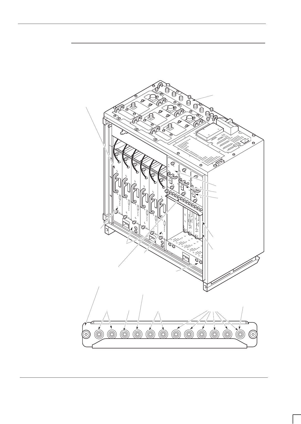
GSM-205-423
Powering up the cabinet
31st Oct 01
Inst. 4–10
Installation & Configuration: Horizon
macro
indoor
CONTROLLED INTRODUCTION
68P02902W08-B
Cabinet and
CBM views
Figure 4-2 shows the cabinet components and enlarged view of CBM showing
circuit breaker buttons.
ig.281.rh
6 CTUs (0 TO 5)
12 A
2 A
4 A
7 A
CCB (0 AND 1) SURF
FANS
BPSMs (A AND B)
7 A
CIRCUIT
BREAKER
MODULE
TWO 2-FAN
UNITS
ONE 4-FAN
UNIT
SIX
TRANSCEIVERS
(CTUs)
PSM0
PSM1
PSM2
SURF
BPSMs A
BPSMs B
CTU 0
CTU 5
CTU 0
Figure 4-2 Diagram of cabinet with expanded view of CBM
GSM-205-423 Sample form 1: Request for connection
31st Oct 01
Installation & Configuration: Horizon
macro
indoor
68P02902W08-B
CONTROLLED INTRODUCTION
Inst. 4–11
Sample form 1: Request for connection
Address ......................................................................................................................................
........................................................................................ Telephone No. ...................................
XXXXXXXXXX ELECTRIC
REQUEST FOR A CONNECTION OF A
CUSTOMER'S INSTALLATION
The electrical installation at the following address will be ready for connection
on (date) ......................................................................................................................................
NOTE : At least 4 full working days' notice is required.
DETAILS OF INSTALLATION
The installation to be connected is :
tick as appropriate
A completely new installation An alteration A rewire
TYPE OF EQUIPMENT CONNECTED LOAD (kW)
Cooker
Water heater
Storage radiators
Other list below
METHOD OF EARTHING tick as appropriate
PME
Cable Sheath
RCD
Other Give Details
NO OF PHASES
1
3
Other Give Details
DECLARATION
The electrical installation, summarised above, complies with the current edition of the Regulations for Electrical
Installations published by the Institution of Electrical Engineers and is now ready for connection to xxxxxxxxx
Electric's supply network.
It is understood that xxxxxxxxxx Electric will carry out tests, required by law, prior to connection, but these tests
will NOT confirm that the installation complies with the IEE Wiring Regulations, NOR will its connection imply
that it is approved by xxxxxxxxxx Electric in any way.
Electrical Installer's Name ............................................................................................................
Address ........................................................................................................................................
........................................................................................... Telephone No. .................................
Signed ................................................................................ Date ...............................................
GSM-205-423
Sample form 1: Request for connection
31st Oct 01
Inst. 4–12
Installation & Configuration: Horizon
macro
indoor
CONTROLLED INTRODUCTION
68P02902W08-B
PARTICULARS OF THE INSTALLATION
(Delete or complete items as appropriate)
Type of Installation New/alteration/addition/to existing installation
Type of earthing (312–03): TN–C TN–S TN–C–S TT IT
(Indicate in the box)
Earth Electrode Resistance . . . . . . . . . . . . . . . ohms
Method of Measurement . . . . . . . . . . . . . . . . . . . . . . . . . . . . . . . . . . . . . . . . . . . . .
Type (542–02–01) and Location . . . . . . . . . . . . . . . . . . . . . . . . . . . . . . . . . . . . . . . .
Characteristics of the supply at the origin of the installation ( 313–01 ):
Nominal voltage volts. . . . . . . . . . . . . . . . .
Frequency Hz Number of phases. . . . . . . . . . . . . . . . . . . . . . . . . . . . . . . . . . . . . . . . . . . . . .
Prospective short–circuit current kA. . . . . . . . . . . . . . . . . . . . . . .
Earth fault loop impedance (Ze) ohms. . . . . . . . . . . . . . . . . . . . . . . .
Maximum demand A per phase. . . . . . . . . .
Overcurrent protective device – Type BS Rating A. . . . . . . . . . . . . . . . . . . . . . . . . . . . . . . .
Main switch or circuit–breaker (460–01–02): Type BS Rating A No of poles . . . . .. . . . . . . . . . . . . . . . . . . . . . . . . . . . . . . . . . . .
(if an r.c.d., rated residual operating current I mA.). . . . . . . . . . . . . . . . . . . . . . . . . . . . . . . . . . . .
Method of protection against indirect contact:
1. Earthed equipotential bonding and automatic disconnection of supply
or
2. Other (Describe) . . . . . . . . . . . . . . . . . . . . . . . . . . . . . . . . . . . . . . . . . . . . . . . . . . . . . . . . . . . . . . . . . . . . . . . . . . . . . . . . . . . .
Main equipotential bonding conductors (413–02–01/02, 547–02–01): Size mm2
. . . . . . . . . . . . . . . . . . . . . . . . . . . .
schedule of Test Results: Continuation pages. . . . . . . . . . . . . . . . . . . . . . . . . . . . . . . . . . . . . . . . . . . . . . . . . . . . . . . . .
Details of departures (if any) from the Wiring Regulations (120–04, 120–05) . . . . . . . . . . . . . . . . . . . . . . . . . . . . . . . . . . . .
Comments on existing installation, where applicable (743–01–01): . . . . . . . . . . . . . . . . . . . . . . . . . . . . . . . . . . . . . . . . . . . .
ascertained
by
enquiry
determined
by
calculation
measured

GSM-205-423 Sample form 2: Completion and inspection form
31st Oct 01
Installation & Configuration: Horizon
macro
indoor
68P02902W08-B
CONTROLLED INTRODUCTION
Inst. 4–13
Sample form 2: Completion and inspection form
DETAILS OF THE INSTALLATION
Client:
Address:
DESIGN
I/We being the person(s) responsible (as indicated by my/our signatures below) for the Design of the electrical installation, particulars of which
are described on Page 3 of this form CERTIFY that the said work for which I/we have been responsible is to the best of my/our knowledge and
belief in accordance with the Regulations for Electrical Installations published by the Institution of Electrical Engineers, 16th Edition, amended
to (3.) (date . . . . . . . . .) except for the departures, if any, stated in this Certificate.
The extent of liability of the signatory is limited to the work described above as the subject of this Certificate.
For the DESIGN of the installation:
Name (In block Letters): Position:
for and on behalf of:
Address:
(2.) Signature: (3.) Date
CONSTRUCTION
I / We being the person(s) responsible ( as indicated by my/our signatures below ) for the Construction of the electrical installation, particulars of
which are described on Page 3 of this form CERTIFY that the said work for which I/we have been responsible is to the best of my/our knowledge
and belief in accordance with the Regulations for Electrical Installations published by the Institution of Electrical Engineers, 16th Edition,
amended to (3.) (date . . . . . . . . .) except for the departures, if any, stated in this Certificate.
The extent of liability of the signatory is limited to the work described above as the subject of this Certificate.
For the CONSTRUCTION of the installation:
Name (In block Letters): Position:
for and on behalf of:
Address:
(2.) Signature: (3.) Date
INSPECTION AND TEST
I / We being the person(s) responsible ( as indicated by my / our signatures below ) for the Inspection and Test of the electrical installation,
particulars of which are described on Page 3 of this form CERTIFY that the said work for which I/we have been responsible is to the best of my/
our knowledge and belief in accordance with the Regulations for Electrical Installations published by the Institution of Electrical Engineers, 16th
Edition, amended to (3.) (date . . . . . . . . .) except for the departures, if any, stated in this Certificate.
The extent of liability of the signatory is limited to the work described above as the subject of this Certificate.
For the INSPECTION AND TEST of the installation:
Name (In block Letters): Position:
for and on behalf of:
Address:
I RECOMMEND that this installation be further inspected and tested after an interval of not more than . . . . years (5.)
(2.) Signature: (3.) Date
(6) page 1 of . . . . pages
FORMS OF COMPLETION AND INSPECTION CERTIFICATE
(as prescribed in the IEE Regulations for Electrical Installations)
(1.) (see Notes overleaf)

GSM-205-423
Sample form 2: Completion and inspection form
31st Oct 01
Inst. 4–14
Installation & Configuration: Horizon
macro
indoor
CONTROLLED INTRODUCTION
68P02902W08-B
This document is intended for the initial certification of a new installation or of an alteration or addition to
an existing installation and of an inspection.
The signatures appended are those of the persons authorised by the companies executing the work of
design, construction and inspection and testing respectively. A signatory authorised to certify more than
one category of work shall sign in each of the appropriate places.
Dates to be inserted.
Where particulars of the installation recorded herein constitute a sufficient schedule for the purpose of
Regulation 514–09–01 further drawings / schedules need not be provided. For other installations the
additional drawings/schedules listed below apply.
Insert here the time interval recommended between periodic inspections. Regard should be paid to
relevant National or Local legislation and reference should be made to chapter 13.
The page numbers of each sheet should be indicated together with the total number of sheets involved.
(4) Schedule of additional records.
1.
2.
3.
4.
5.
6.
(6) page 2 of . . . . pages

31st Oct 01
Installation & Configuration: Horizon
macro
indoor
68P02902W08-B
CONTROLLED INTRODUCTION
i
Chapter 5
Decommissioning of cabinet

GSM-205-423
31st Oct 01
ii
Installation & Configuration: Horizon
macro
indoor
CONTROLLED INTRODUCTION
68P02902W08-B

GSM-205-423
31st Oct 01
Installation & Configuration: Horizon
macro
indoor
68P02902W08-B
CONTROLLED INTRODUCTION
iii
Chapter 5
Decommissioning of cabinet i. . . . . . . . . . . . . . . . . . . . . . . . . . . . . . . . . . .
Decommissioning Horizonmacro indoor Inst. 5–1. . . . . . . . . . . . . . . . . . . . . . . . . . . . . . . . .
Introduction to decommission procedures Inst. 5–1. . . . . . . . . . . . . . . . . . . . . . . . . .
Before cabinet decommission Inst. 5–1. . . . . . . . . . . . . . . . . . . . . . . . . . . . . . . . . . . .
To decommission using checklist Inst. 5–1. . . . . . . . . . . . . . . . . . . . . . . . . . . . . . . . . .
Initial decommission checks Inst. 5–1. . . . . . . . . . . . . . . . . . . . . . . . . . . . . . . . . . . . . .
Powering down the cabinet Inst. 5–2. . . . . . . . . . . . . . . . . . . . . . . . . . . . . . . . . . . . . .
Disconnection of cabinet cables Inst. 5–2. . . . . . . . . . . . . . . . . . . . . . . . . . . . . . . . . .
Eyebolt positions and safety Inst. 5–3. . . . . . . . . . . . . . . . . . . . . . . . . . . . . . . . . . . . . .
Removing upper cabinet in stacked configuration Inst. 5–4. . . . . . . . . . . . . . . . . . .
View of eyebolt positions Inst. 5–5. . . . . . . . . . . . . . . . . . . . . . . . . . . . . . . . . . . . . . . . .
Removing CCBs Inst. 5–6. . . . . . . . . . . . . . . . . . . . . . . . . . . . . . . . . . . . . . . . . . . . . . . .
Removing a stacking bracket Inst. 5–7. . . . . . . . . . . . . . . . . . . . . . . . . . . . . . . . . . . .
Removing floor mounted cabinet Inst. 5–8. . . . . . . . . . . . . . . . . . . . . . . . . . . . . . . . .
Returning equipment to Motorola Inst. 5–8. . . . . . . . . . . . . . . . . . . . . . . . . . . . . . . . .
Horizonmacro indoor decommission checklist Inst. 5–9. . . . . . . . . . . . . . . . . . . . . .

GSM-205-423
31st Oct 01
iv
Installation & Configuration: Horizon
macro
indoor
CONTROLLED INTRODUCTION
68P02902W08-B

GSM-205-423 Decommissioning Horizonmacro indoor
31st Oct 01
Installation & Configuration: Horizon
macro
indoor
68P02902W08-B
CONTROLLED INTRODUCTION
Inst. 5–1
Decommissioning Horizon
macro
indoor
Introduction to
decommission
procedures
This chapter describes how to decommission a Horizon
macro
indoor cabinet. To
decommission equipment not supplied by Motorola, for example E1/T1 links,
power supplies and antennas, refer to the vendor instructions.
WARNING Hazardous voltages in excess of 240 V ac may exist
inside a Horizon
macro
indoor cabinet.
Use extreme caution when working on a Horizon
macro
Indoor cabinet with power applied. Remove all rings,
watches and other jewellery.
In a stacked cabinet configuration, check that the bottom
cabinet is bolted to the floor using the supplied plinth. IF
NOT, this presents a danger of toppling that the
decommissioning personnel must take into account.
Before cabinet
decommission
Read all the earlier chapters of this installation section, before attempting to
decommission a Horizon
macro
indoor cabinet.
To
decommission
using checklist
The following procedure should be recorded by use of the checklist, to check
that each action has been completed. Photocopy the checklist as often as
required; do not write on the original manual copy.
Initial
decommission
checks
When starting to decommission a Horizon
macro
indoor cabinet:
SContact the OMC-R and ensure the cabinet is taken out of service.
SOpen the cabinet door and power down the cabinet, as described in
Powering down the cabinet in this section.
SEnsure that NO power is connected to the enclosure.
SEnsue that sufficient packing cartons are available to pack the
decommissioned equipment.
SEnsure any unused items, such as hood pins, have been retrieved from
storage elsewhere.

GSM-205-423
Decommissioning Horizonmacro indoor
31st Oct 01
Inst. 5–2
Installation & Configuration: Horizon
macro
indoor
CONTROLLED INTRODUCTION
68P02902W08-B
Powering down
the cabinet
To power down the cabinet:
1. Press and release all circuit breaker buttons to the out (off) position.
2. Switch each PSM to the OUTPUT DISABLE position.
3. Switch off the external power supply to the cabinet.
Disconnection
of cabinet
cables
Follow this procedure to disconnect a Horizon
macro
indoor cabinet cables for
decommissioning:
WARNING Untidy disconnected cables can create a trip hazard to
personnel using the site.
Checking and disconnecting from power source
To disconnect power supply cables:
1. Check the cabinet for signs of damage.
2. Ensure that power is NOT present at the cabinet.
3. Disconnect the ac or dc input power cables, from the power source.
4. Disconnect the ac or dc input power cables, from the cabinet.
5. Stow disconnected cables safely.
6. If the power cable is not to be used again for other equipment, dispose of
safely.
Disconnecting all remaining external cables
To disconnect remaining cables:
1. Disconnect all cabling from interface panel.
2. Disconnect all RF cables to antennas or other cabinets.
3. Disconnect fibre optic cables between main cabinet and any extension
cabinets.
4. Disconnect the earth cable.
5. Stow disconnected cables safely.
6. If the cables are not to be used again for other equipment, dispose of
safely.

GSM-205-423 Decommissioning Horizonmacro indoor
31st Oct 01
Installation & Configuration: Horizon
macro
indoor
68P02902W08-B
CONTROLLED INTRODUCTION
Inst. 5–3
Eyebolt
positions and
safety
There are four eyebolt positions to enable lifting of a second cabinet from the
top of the first cabinet stacking bracket. Eyebolts are available from Motorola
for this purpose (part number 0386436N01 – Eyebolt, M8).
WARNING The cabinet can weigh as much as 130 kg with stacking
bracket and CCB. Handle cabinets with extreme caution,
and in accordance with any national or regional health and
safety regulations.
Horizon
macro
cabinets are heavy and should not be
installed without the use of lifting equipment unless
sufficient personnel are available to ensure that Health
and Safety regulations are not breached.
Eyebolts used to lift the cabinet must be of the collared
type, manufactured to CE conformity, and must have
sufficient safe working load to lift the cabinet, in
accordance with national or regional health and safety
regulations.
Motorola recommends the use of slings in conjunction with
hydraulic lifting apparatus for moving and positioning
Horizon
macro
cabinets.
The four screw locations used for hood pins must NOT be
used for eyebolts.
In addition to these points, refer to and comply with any
local regulations that govern the use of lifting equipment.
For the subsequent use of eyebolts, there may be local regulations that govern
the use of lifting equipment and stipulate a test and/or examination regime. If
the eyebolts are to be used, ensure that all such regulations are met.
Eyebolts can be fitted into the four designated cabinet top panel locations,
shown in Figure 5-1, after removal of the screws. These locations are identified
with an eyebolt symbol and the word LIFT. The eyebolt locations are also used
for stacking bracket attachment.

GSM-205-423
Decommissioning Horizonmacro indoor
31st Oct 01
Inst. 5–4
Installation & Configuration: Horizon
macro
indoor
CONTROLLED INTRODUCTION
68P02902W08-B
Removing
upper cabinet in
stacked
configuration
WARNING Check that the bottom cabinet is bolted to the floor using
the supplied plinth. IF NOT, this presents a danger of
toppling that the decommissioning personnel must take
into account.
To remove the upper cabinet in a stacked configuration:
1. If CCBs are fitted to upper cabinet, remove as described in Removing
CCBs in this section.
2. If stacking bracket is fitted to upper cabinet, remove as described in
Removing a stacking bracket in this section.
WARNING The cabinet can weigh up to 130 kg if fully equipped.
Handle each cabinet with extreme caution and in
accordance with local health and safety regulations.
Eyebolts are to be used with lifting equipment, and these
must be located in the correct position as shown in
Figure 5-1. The four screw locations used for hood pins
must NOT be used for eyebolts.
Before attempting to insert the eyebolts, visually check
each one for damage. If any damage is apparent, DO
NOT USE.
The eyebolts must not be over tightened; hand tight is
sufficient. Do not tighten eyebolts with a t-bar or
spanner. Screw the eyebolt fully into the lifting point so
that no thread is left exposed.
3. Fit eyebolts to the locations, identified with an eyebolt symbol and the
word LIFT. Attach eyebolts to suitable lifting equipment.
4. Remove the four bolts holding upper cabinet plinth to stacking bracket.
5. Lift upper cabinet, complete with plinth, off stacking bracket, and lower to
floor.
6. Remove the two M10 bolts securing plinth to cabinet, and slide apart.
7. Pack upper cabinet and plinth in separate containers, for storage,
transport or safe disposal.
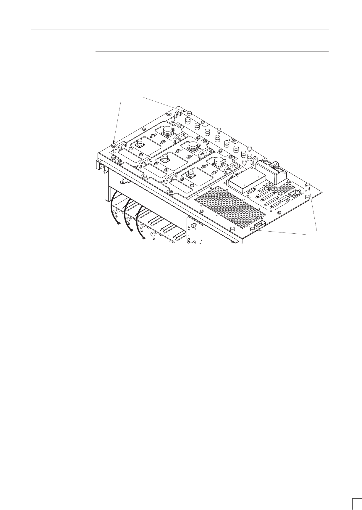
GSM-205-423 Decommissioning Horizonmacro indoor
31st Oct 01
Installation & Configuration: Horizon
macro
indoor
68P02902W08-B
CONTROLLED INTRODUCTION
Inst. 5–5
View of eyebolt
positions
Figure 5-1 shows the positions to which eyebolts can be fitted.
EYEBOLT POSITIONS
EYEBOLT POSITIONS
Figure 5-1 Eye bolt positions

GSM-205-423
Decommissioning Horizonmacro indoor
31st Oct 01
Inst. 5–6
Installation & Configuration: Horizon
macro
indoor
CONTROLLED INTRODUCTION
68P02902W08-B
Removing
CCBs
The removal off CCBs is accomplished in two stages:
SRemoving the CCB basket from the stacking bracket.
SSeparating CCBs from CCB basket.
Removing CCB basket from stacking bracket
To remove the CCB basket:
1. Remove the stacking bracket front cover by applying gentle pressure to
the outer edges, while easing the cover up and pulling it away from the
bracket.
Figure 5-2 in Removing a stacking bracket shows how to remove the stacking
bracket front cover.
2. Disconnect the power cable to each CCB from the single connector
(marked CCB) on the interface panel.
3. Loosen the three captive screws attaching CCB basket bar to basket and
the two captive screws securing CCB basket bar to the sides of the
stacking bracket. Remove the bar
4. Disconnect the six N-type to N-type RF cables from the CCB inputs and
the feedthrough plates.
5. Slide basket part way out of the stacking bracket, and disconnect
antennas to CCBs.
6. Remove the CCB basket, complete with CCBs, from the stacking bracket.
Separating CCBs from CCB basket
To separate the CCBs from the CCB basket:
1. Place the CCB basket, complete with CCBs, onto a flat surface.
2. Disconnect and remove the phasing lead between CCB control boards.
3. Remove the four M4 screws securing each control board cover, and
remove the CCB control boards.
4. Remove the six screws securing each CCB to the basket, (four M6 screws
on the front and two M8 screws at the back).
5. Remove the CCBs from the basket
6. Place the CCBs, control boards and associated cables in box for storage,
transport or safe disposal and retain the CCB basket to be packaged with
stacking bracket.
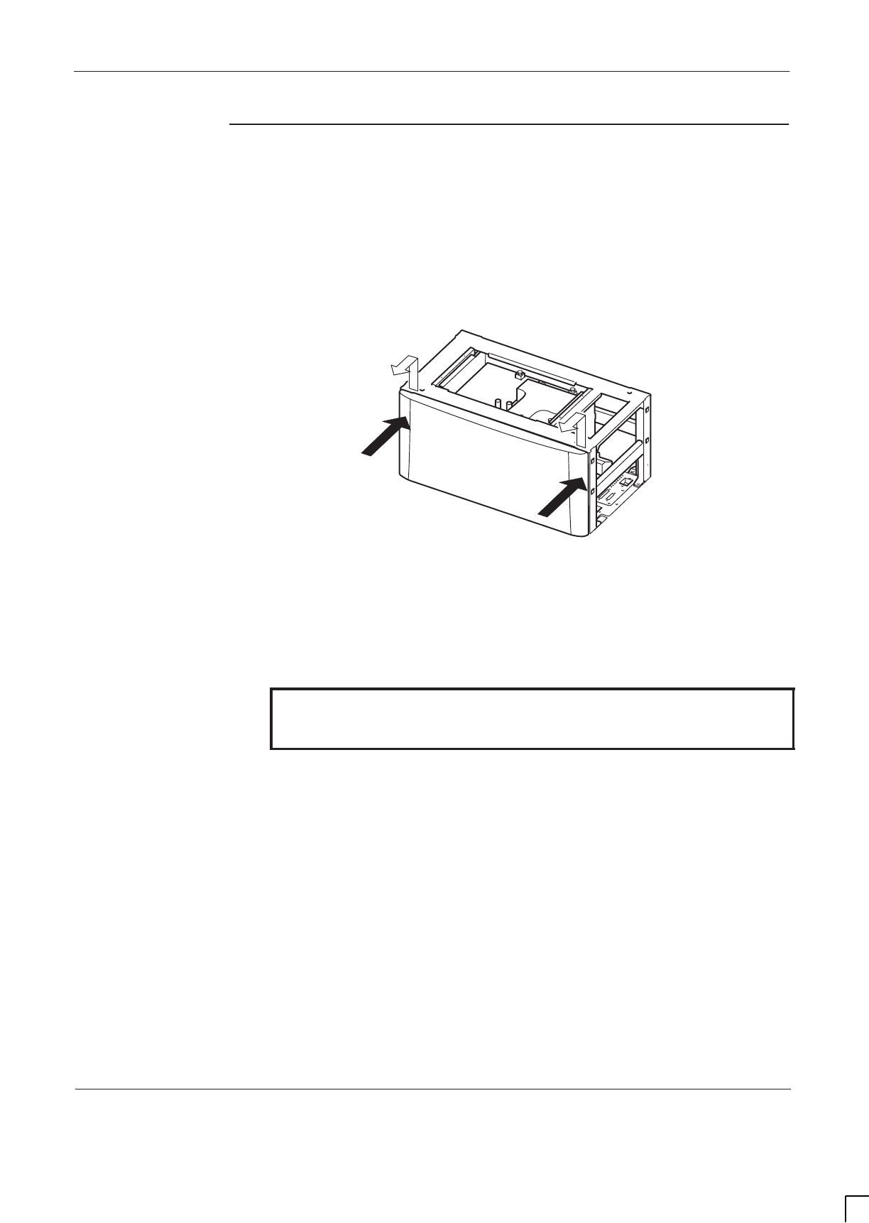
GSM-205-423 Decommissioning Horizonmacro indoor
31st Oct 01
Installation & Configuration: Horizon
macro
indoor
68P02902W08-B
CONTROLLED INTRODUCTION
Inst. 5–7
Removing a
stacking
bracket
To remove a stacking bracket:
1. Remove the stacking bracket front cover by applying gentle pressure to
the outer edges, while easing the cover up and pulling it away from the
bracket.
Figure 5-2 shows how to remove the stacking bracket front cover.
Lift and pull
Apply gentle
pressure
Apply gentle
pressure ig.334.rh
Figure 5-2 Removing the stacking bracket front cover
2. Loosen and remove the eight M8 screws holding the stacking bracket to
the cabinet top, and retain.
WARNING The stacking bracket can weigh as much as 15 kg (more if
CCB is contained in CCB basket). Observe the correct
lifting precautions when handling the stacking bracket.
3. Lift the stacking bracket off the cabinet.
4. Fit eight previously removed M8 screws to correct cabinet screw points
(see Figure 2-5). Tighten to correct torque (see
Installation &
Configuration: GSM-205-423
Site requirements and considerations).
5. Place the stacking bracket, with CCB basket (if previously removed), in a
box for storage, transport or safe disposal.
If the upper cabinet only is being decommissioned and an optional hood is
required after stacking bracket removal refer to
Installation & Configuration:
GSM-205-423
Fitting the optional hood.

GSM-205-423
Decommissioning Horizonmacro indoor
31st Oct 01
Inst. 5–8
Installation & Configuration: Horizon
macro
indoor
CONTROLLED INTRODUCTION
68P02902W08-B
Removing floor
mounted
cabinet
WARNING The cabinet can weigh up to 130 kg if fully equipped.
Handle each cabinet with extreme caution, and in
accordance with local health and safety regulations.
Horizon
macro
cabinets are heavy and should not be
installed without the use of lifting equipment unless
sufficient personnel are available to ensure that Health
and Safety regulations are not breached.
To remove a floor mounted cabinet for decommissioning:
1. Unscrew the two front bolts holding the cabinet to the plinth.
2. Slide the cabinet out of the plinth.
3. Unscrew the plinth anchor bolts and lift the plinth from the floor.
4. Carefully pack all bolts, washers and other removed items.
5. Pack the cabinet and plinth in separate containers, for storage, transport
or safe disposal.
Returning
equipment to
Motorola
If sending equipment back to Motorola, seal the shipping containers and return,
as advised, by the Motorola in-country project manager.

GSM-205-423 Decommissioning Horizonmacro indoor
31st Oct 01
Installation & Configuration: Horizon
macro
indoor
68P02902W08-B
CONTROLLED INTRODUCTION
Inst. 5–9
Horizon
macro
indoor
decommission
checklist
Copy this sheet and fill in the checklist in Table 5-1.
NAME_______________________________________DA TE_________
SIGNATURE _________________________________
SITE NAME __________________________________
EQUIPMENT TYPE ____________________________
NATIONAL ID ____________________________
Table 5-1 Checklist of completed decommissioning steps
ACTION Yes No N/A
Horizon
macro
Indoor cabinet taken out of service by
the OMC-R
Packing material (including polythene bag) on site
Is cabinet damaged? If yes, detail in comments box
Hood (if fitted) removed and packed
Power cable disconnected
Interface panel cables disconnected
RF cables disconnected
Extension cabinet fibre optic cables disconnected
Earth cable disconnected
CCBs (if fitted) removed and packed
Stacking bracket (if fitted) removed and packed
Cabinet removed from plinth and packed
Plinth removed from floor and packed
All loose cables stowed and secured
COMMENTS

GSM-205-423
Decommissioning Horizonmacro indoor
31st Oct 01
Inst. 5–10
Installation & Configuration: Horizon
macro
indoor
CONTROLLED INTRODUCTION
68P02902W08-B

CHAPTER 2
FRU REPLACEMENT
PROCEDURES
CHAPTER 1
ROUTINE MAINTENANCE


31st Oct 01
Maintenance Information: Horizon
macro
indoor
68P02902W09-B
CONTROLLED INTRODUCTION
i
Category 523
Maintenance Information (Maint.)

GSM-205-523
31st Oct 01
ii
Maintenance Information: Horizon
macro
indoor
CONTROLLED INTRODUCTION
68P02902W09-B

GSM-205-523
31st Oct 01
Maintenance Information: Horizon
macro
indoor
68P02902W09-B
CONTROLLED INTRODUCTION
iii
Category 523
Maintenance Information (Maint.) i. . . . . . . . . . . . . . . . . . . . . . . . . . . . . . . . . . .
Chapter 1
Routine maintenance i. . . . . . . . . . . . . . . . . . . . . . . . . . . . . . . . . . . . . . . . . .
Routine maintenance overview Maint. 1–1. . . . . . . . . . . . . . . . . . . . . . . . . . . . . . . . . . . . . . . .
In this chapter Maint. 1–1. . . . . . . . . . . . . . . . . . . . . . . . . . . . . . . . . . . . . . . . . . . . . . . . . .
Safety Maint. 1–1. . . . . . . . . . . . . . . . . . . . . . . . . . . . . . . . . . . . . . . . . . . . . . . . . . . . . . . . .
Reporting faulty devices Maint. 1–1. . . . . . . . . . . . . . . . . . . . . . . . . . . . . . . . . . . . . . . . .
Routine maintenance intervals Maint. 1–2. . . . . . . . . . . . . . . . . . . . . . . . . . . . . . . . . . . .
Cleaning agents Maint. 1–2. . . . . . . . . . . . . . . . . . . . . . . . . . . . . . . . . . . . . . . . . . . . . . . .
Tools Maint. 1–2. . . . . . . . . . . . . . . . . . . . . . . . . . . . . . . . . . . . . . . . . . . . . . . . . . . . . . . . . .
Assumptions – door, hood, and stacking bracket Maint. 1–3. . . . . . . . . . . . . . . . . . . .
Door operation Maint. 1–3. . . . . . . . . . . . . . . . . . . . . . . . . . . . . . . . . . . . . . . . . . . . . . . . .
Hood removal and refitting Maint. 1–3. . . . . . . . . . . . . . . . . . . . . . . . . . . . . . . . . . . . . . .
Stacking bracket removal Maint. 1–3. . . . . . . . . . . . . . . . . . . . . . . . . . . . . . . . . . . . . . . .
Stacking bracket front cover removal and fit Maint. 1–4. . . . . . . . . . . . . . . . . . . . . . . .
6-monthly maintenance procedures Maint. 1–5. . . . . . . . . . . . . . . . . . . . . . . . . . . . . . . . . . . .
Type of procedures Maint. 1–5. . . . . . . . . . . . . . . . . . . . . . . . . . . . . . . . . . . . . . . . . . . . .
Cleaning inlets and exhaust grilles Maint. 1–5. . . . . . . . . . . . . . . . . . . . . . . . . . . . . . . .
Replacing the air filter Maint. 1–5. . . . . . . . . . . . . . . . . . . . . . . . . . . . . . . . . . . . . . . . . . .
12-monthly maintenance procedures Maint. 1–6. . . . . . . . . . . . . . . . . . . . . . . . . . . . . . . . . . .
Summary of 12-monthly procedures Maint. 1–6. . . . . . . . . . . . . . . . . . . . . . . . . . . . . . .
Checking and cleaning fans Maint. 1–6. . . . . . . . . . . . . . . . . . . . . . . . . . . . . . . . . . . . . .
Cabinet modules in operational positions Maint. 1–7. . . . . . . . . . . . . . . . . . . . . . . . . .
Checking normal operation Maint. 1–8. . . . . . . . . . . . . . . . . . . . . . . . . . . . . . . . . . . . . . .
Annual check of the installation Maint. 1–8. . . . . . . . . . . . . . . . . . . . . . . . . . . . . . . . . . .
24-monthly maintenance procedures Maint. 1–9. . . . . . . . . . . . . . . . . . . . . . . . . . . . . . . . . . .
Summary of 24-monthly procedures Maint. 1–9. . . . . . . . . . . . . . . . . . . . . . . . . . . . . . .
Mechanical inspection of cabinet, locks and hinges Maint. 1–10. . . . . . . . . . . . . . . . .
Chapter 2
FRU replacement procedures i. . . . . . . . . . . . . . . . . . . . . . . . . . . . . . . . . .
Overview of replacement procedures Maint. 2–1. . . . . . . . . . . . . . . . . . . . . . . . . . . . . . . . . . .
Field Replaceable Units (FRUs) Maint. 2–1. . . . . . . . . . . . . . . . . . . . . . . . . . . . . . . . . . .
FRU list Maint. 2–1. . . . . . . . . . . . . . . . . . . . . . . . . . . . . . . . . . . . . . . . . . . . . . . . . . . . . . . .
Torque values Maint. 2–2. . . . . . . . . . . . . . . . . . . . . . . . . . . . . . . . . . . . . . . . . . . . . . . . . .
FRU locations within cabinet Maint. 2–3. . . . . . . . . . . . . . . . . . . . . . . . . . . . . . . . . . . . .
Additional replacement parts Maint. 2–4. . . . . . . . . . . . . . . . . . . . . . . . . . . . . . . . . . . . . . . . . .
Policy on non-FRU parts Maint. 2–4. . . . . . . . . . . . . . . . . . . . . . . . . . . . . . . . . . . . . . . . .
List of non-FRU parts Maint. 2–4. . . . . . . . . . . . . . . . . . . . . . . . . . . . . . . . . . . . . . . . . . . .
Procedure for replacing non-FRU parts Maint. 2–4. . . . . . . . . . . . . . . . . . . . . . . . . . . .
CBIA attachment screws Maint. 2–4. . . . . . . . . . . . . . . . . . . . . . . . . . . . . . . . . . . . . . . . .
Replacing a door Maint. 2–5. . . . . . . . . . . . . . . . . . . . . . . . . . . . . . . . . . . . . . . . . . . . . . . . . . . . .
Introduction to door replacement Maint. 2–5. . . . . . . . . . . . . . . . . . . . . . . . . . . . . . . . . .
Views of door Maint. 2–5. . . . . . . . . . . . . . . . . . . . . . . . . . . . . . . . . . . . . . . . . . . . . . . . . . .
Replacement of door Maint. 2–6. . . . . . . . . . . . . . . . . . . . . . . . . . . . . . . . . . . . . . . . . . . .

GSM-205-523
31st Oct 01
iv
Maintenance Information: Horizon
macro
indoor
CONTROLLED INTRODUCTION
68P02902W09-B
Replacing a cabinet heat sensor Maint. 2–7. . . . . . . . . . . . . . . . . . . . . . . . . . . . . . . . . . . . . . .
Overview of heat sensors Maint. 2–7. . . . . . . . . . . . . . . . . . . . . . . . . . . . . . . . . . . . . . . .
Procedure for heat sensor replacement Maint. 2–7. . . . . . . . . . . . . . . . . . . . . . . . . . . .
Replacing a hood Maint. 2–8. . . . . . . . . . . . . . . . . . . . . . . . . . . . . . . . . . . . . . . . . . . . . . . . . . . .
Introduction to hood replacement Maint. 2–8. . . . . . . . . . . . . . . . . . . . . . . . . . . . . . . . .
View of hood Maint. 2–8. . . . . . . . . . . . . . . . . . . . . . . . . . . . . . . . . . . . . . . . . . . . . . . . . . .
Replacing the hood Maint. 2–8. . . . . . . . . . . . . . . . . . . . . . . . . . . . . . . . . . . . . . . . . . . . .
Replacing a stacking bracket Maint. 2–9. . . . . . . . . . . . . . . . . . . . . . . . . . . . . . . . . . . . . . . . . .
View of stacking bracket Maint. 2–9. . . . . . . . . . . . . . . . . . . . . . . . . . . . . . . . . . . . . . . . .
Procedure to replace a stacking bracket Maint. 2–10. . . . . . . . . . . . . . . . . . . . . . . . . . .
Replacing a fan module Maint. 2–11. . . . . . . . . . . . . . . . . . . . . . . . . . . . . . . . . . . . . . . . . . . . . . .
Introduction to fan replacement Maint. 2–11. . . . . . . . . . . . . . . . . . . . . . . . . . . . . . . . . . .
View of fan modules Maint. 2–11. . . . . . . . . . . . . . . . . . . . . . . . . . . . . . . . . . . . . . . . . . . . .
Identifying fan module Maint. 2–12. . . . . . . . . . . . . . . . . . . . . . . . . . . . . . . . . . . . . . . . . . .
Replacing fan modules Maint. 2–12. . . . . . . . . . . . . . . . . . . . . . . . . . . . . . . . . . . . . . . . . .
Replacing a circuit breaker module (CBM) Maint. 2–13. . . . . . . . . . . . . . . . . . . . . . . . . . . . . . .
Preconditions for CBM replacement Maint. 2–13. . . . . . . . . . . . . . . . . . . . . . . . . . . . . . .
Views of CBM Maint. 2–13. . . . . . . . . . . . . . . . . . . . . . . . . . . . . . . . . . . . . . . . . . . . . . . . . .
Replacing a CBM Maint. 2–14. . . . . . . . . . . . . . . . . . . . . . . . . . . . . . . . . . . . . . . . . . . . . . .
Replacing a power supply module (PSM) Maint. 2–15. . . . . . . . . . . . . . . . . . . . . . . . . . . . . . .
Introduction
to PSM replacement Maint. 2–15. . . . . . . . . . . . . . . . . . . . . . . . . . . . . . . . . . . . . . . . . . . .
Preconditions for PSM replacement Maint. 2–15. . . . . . . . . . . . . . . . . . . . . . . . . . . . . . .
View of PSM Maint. 2–15. . . . . . . . . . . . . . . . . . . . . . . . . . . . . . . . . . . . . . . . . . . . . . . . . . .
Replacing a non-redundant PSM Maint. 2–16. . . . . . . . . . . . . . . . . . . . . . . . . . . . . . . . .
Replacing a redundant PSM Maint. 2–16. . . . . . . . . . . . . . . . . . . . . . . . . . . . . . . . . . . . .
Replacing a hold-up battery module Maint. 2–17. . . . . . . . . . . . . . . . . . . . . . . . . . . . . . . . . . . .
To Replace a hold-up battery module Maint. 2–17. . . . . . . . . . . . . . . . . . . . . . . . . . . . . .
Replacing a CTU Maint. 2–19. . . . . . . . . . . . . . . . . . . . . . . . . . . . . . . . . . . . . . . . . . . . . . . . . . . . .
Preconditions for CTU replacement Maint. 2–19. . . . . . . . . . . . . . . . . . . . . . . . . . . . . . .
View of CTU Maint. 2–19. . . . . . . . . . . . . . . . . . . . . . . . . . . . . . . . . . . . . . . . . . . . . . . . . . . .
Replacement procedure for CTU Maint. 2–20. . . . . . . . . . . . . . . . . . . . . . . . . . . . . . . . . .
Replacing a SURF module Maint. 2–22. . . . . . . . . . . . . . . . . . . . . . . . . . . . . . . . . . . . . . . . . . . .
Preconditions for SURF replacement Maint. 2–22. . . . . . . . . . . . . . . . . . . . . . . . . . . . . .
View of the SURF Maint. 2–22. . . . . . . . . . . . . . . . . . . . . . . . . . . . . . . . . . . . . . . . . . . . . . .
Replacing a SURF module Maint. 2–23. . . . . . . . . . . . . . . . . . . . . . . . . . . . . . . . . . . . . . .
Replacing a Tx block, HCU or plate Maint. 2–25. . . . . . . . . . . . . . . . . . . . . . . . . . . . . . . . . . . .
Introduction to Tx block replacement Maint. 2–25. . . . . . . . . . . . . . . . . . . . . . . . . . . . . .
Views of typical Tx block Maint. 2–26. . . . . . . . . . . . . . . . . . . . . . . . . . . . . . . . . . . . . . . . .
Replacing a Tx block Maint. 2–27. . . . . . . . . . . . . . . . . . . . . . . . . . . . . . . . . . . . . . . . . . . .
Blanking plate, feedthrough plate or HCU replacement Maint. 2–28. . . . . . . . . . . . . .
Replacing a CCB Maint. 2–29. . . . . . . . . . . . . . . . . . . . . . . . . . . . . . . . . . . . . . . . . . . . . . . . . . . .
Overview of CCB replacement Maint. 2–29. . . . . . . . . . . . . . . . . . . . . . . . . . . . . . . . . . . .
View of CCBs in stacking bracket Maint. 2–29. . . . . . . . . . . . . . . . . . . . . . . . . . . . . . . . .
Removing CCBs and CCB control boards Maint. 2–30. . . . . . . . . . . . . . . . . . . . . . . . . .
Fitting replacement CCBs and CCB control boards Maint. 2–31. . . . . . . . . . . . . . . . .

GSM-205-523
31st Oct 01
Maintenance Information: Horizon
macro
indoor
68P02902W09-B
CONTROLLED INTRODUCTION
v
Digital module replacement (MCUF, NIU, FMUX, BPSM, Alarm) Maint. 2–32. . . . . . . . . . . .
Introduction to digital module replacement Maint. 2–32. . . . . . . . . . . . . . . . . . . . . . . . .
Diagram of digital modules Maint. 2–32. . . . . . . . . . . . . . . . . . . . . . . . . . . . . . . . . . . . . . .
Replacing digital modules Maint. 2–33. . . . . . . . . . . . . . . . . . . . . . . . . . . . . . . . . . . . . . . .
Redundant MCUF firmware compatibility Maint. 2–35. . . . . . . . . . . . . . . . . . . . . . . . . . . . . . . .
Overview of MCUF firmware compatibility Maint. 2–35. . . . . . . . . . . . . . . . . . . . . . . . . .
Checking MCUF firmware compatibility Maint. 2–35. . . . . . . . . . . . . . . . . . . . . . . . . . . .
Updating redundant MCUF firmware Maint. 2–35. . . . . . . . . . . . . . . . . . . . . . . . . . . . . .
Testing MCUF redundancy Maint. 2–38. . . . . . . . . . . . . . . . . . . . . . . . . . . . . . . . . . . . . . .

GSM-205-523
31st Oct 01
vi
Maintenance Information: Horizon
macro
indoor
CONTROLLED INTRODUCTION
68P02902W09-B

31st Oct 01
Maintenance Information: Horizon
macro
indoor
68P02902W09-B
CONTROLLED INTRODUCTION
i
Chapter 1
Routine maintenance

GSM-205-523
31st Oct 01
ii
Maintenance Information: Horizon
macro
indoor
CONTROLLED INTRODUCTION
68P02902W09-B

GSM-205-523
31st Oct 01
Maintenance Information: Horizon
macro
indoor
68P02902W09-B
CONTROLLED INTRODUCTION
iii
Chapter 1
Routine maintenance i. . . . . . . . . . . . . . . . . . . . . . . . . . . . . . . . . . . . . . . . . .
Routine maintenance overview Maint. 1–1. . . . . . . . . . . . . . . . . . . . . . . . . . . . . . . . . . . . . . . .
In this chapter Maint. 1–1. . . . . . . . . . . . . . . . . . . . . . . . . . . . . . . . . . . . . . . . . . . . . . . . . .
Safety Maint. 1–1. . . . . . . . . . . . . . . . . . . . . . . . . . . . . . . . . . . . . . . . . . . . . . . . . . . . . . . . .
Reporting faulty devices Maint. 1–1. . . . . . . . . . . . . . . . . . . . . . . . . . . . . . . . . . . . . . . . .
Routine maintenance intervals Maint. 1–2. . . . . . . . . . . . . . . . . . . . . . . . . . . . . . . . . . . .
Cleaning agents Maint. 1–2. . . . . . . . . . . . . . . . . . . . . . . . . . . . . . . . . . . . . . . . . . . . . . . .
Tools Maint. 1–2. . . . . . . . . . . . . . . . . . . . . . . . . . . . . . . . . . . . . . . . . . . . . . . . . . . . . . . . . .
Assumptions – door, hood, and stacking bracket Maint. 1–3. . . . . . . . . . . . . . . . . . . .
Door operation Maint. 1–3. . . . . . . . . . . . . . . . . . . . . . . . . . . . . . . . . . . . . . . . . . . . . . . . .
Hood removal and refitting Maint. 1–3. . . . . . . . . . . . . . . . . . . . . . . . . . . . . . . . . . . . . . .
Stacking bracket removal Maint. 1–3. . . . . . . . . . . . . . . . . . . . . . . . . . . . . . . . . . . . . . . .
Stacking bracket front cover removal and fit Maint. 1–4. . . . . . . . . . . . . . . . . . . . . . . .
6-monthly maintenance procedures Maint. 1–5. . . . . . . . . . . . . . . . . . . . . . . . . . . . . . . . . . . .
Type of procedures Maint. 1–5. . . . . . . . . . . . . . . . . . . . . . . . . . . . . . . . . . . . . . . . . . . . .
Cleaning inlets and exhaust grilles Maint. 1–5. . . . . . . . . . . . . . . . . . . . . . . . . . . . . . . .
Replacing the air filter Maint. 1–5. . . . . . . . . . . . . . . . . . . . . . . . . . . . . . . . . . . . . . . . . . .
12-monthly maintenance procedures Maint. 1–6. . . . . . . . . . . . . . . . . . . . . . . . . . . . . . . . . . .
Summary of 12-monthly procedures Maint. 1–6. . . . . . . . . . . . . . . . . . . . . . . . . . . . . . .
Checking and cleaning fans Maint. 1–6. . . . . . . . . . . . . . . . . . . . . . . . . . . . . . . . . . . . . .
Cabinet modules in operational positions Maint. 1–7. . . . . . . . . . . . . . . . . . . . . . . . . .
Checking normal operation Maint. 1–8. . . . . . . . . . . . . . . . . . . . . . . . . . . . . . . . . . . . . . .
Annual check of the installation Maint. 1–8. . . . . . . . . . . . . . . . . . . . . . . . . . . . . . . . . . .
24-monthly maintenance procedures Maint. 1–9. . . . . . . . . . . . . . . . . . . . . . . . . . . . . . . . . . .
Summary of 24-monthly procedures Maint. 1–9. . . . . . . . . . . . . . . . . . . . . . . . . . . . . . .
Mechanical inspection of cabinet, locks and hinges Maint. 1–10. . . . . . . . . . . . . . . . .

GSM-205-523
31st Oct 01
iv
Maintenance Information: Horizon
macro
indoor
CONTROLLED INTRODUCTION
68P02902W09-B

GSM-205-523 Routine maintenance overview
31st Oct 01
Maintenance Information: Horizon
macro
indoor
68P02902W09-B
CONTROLLED INTRODUCTION
Maint. 1–1
Routine maintenance overview
In this chapter
This chapter contains the procedures for the routine maintenance of a
Horizon
macro
Indoor base transceiver station (BTS).
NOTE Since a Horizon
macro
BTS operates as part of a network,
the procedures in this chapter must be performed in
conjunction with the relevant network procedures in the
associated OMC-R manuals. Before attempting any work
on the cabinet, contact should be made with the OMC-R
to advise on proposed activity.
Safety
WARNING Potentially lethal voltages and high energy sources are
present in the cabinet when the external ac mains isolator
switch is set to the on position and/or batteries are
connected. Remove rings, watches and jewellery before
starting these procedures, and exercise extreme caution
when working on the equipment.
Maintenance procedures on this equipment must only be
carried out by suitably qualified personnel.
Safety features are built into the equipment to protect against the potentially
lethal hazards that exist. All statements regarding safety within these routine
maintenance procedures must be adhered to when working on the equipment.
Reporting
faulty devices
During routine maintenance and FRU replacement procedures, it may be
possible to identify signs of damage that might indicate a problem that could
repeat, cause additional damage, or be a symptom of a failure elsewhere.
Analysis of the problem may identify the fault and make corrective action
possible.
Whenever a safety issue arises:
SInform the OMC-R that an equipment safety problem has been identified.
SMake the equipment concerned safe, for example, by removing power.
SMake no further attempt to tamper with the equipment..
SReport the problem directly to GSM Customer Network Resolution Centre
+44 (0)1793 565444 (telephone) and follow up with a written report by fax
+44 (0)1793 430987 (fax).
SCollect evidence from the equipment under the guidance of the Customer
Network Resolution Centre.
SSeek local office advice.

GSM-205-523
Routine maintenance overview
31st Oct 01
Maint. 1–2
Maintenance Information: Horizon
macro
indoor
CONTROLLED INTRODUCTION
68P02902W09-B
Routine
maintenance
intervals
Routine maintenance for Horizon
macro
indoor installations is recommended at
the intervals shown in Table 1-1:
Table 1-1 Routine maintenance schedule
6 months 12 months 24 months
Ensure that cabinet
air inlets, exhaust
grilles and filter (if
fitted) are not
blocked.
Annual check of the
installation. Inspect general
mechanical condition of
the cabinet.
Check normal operation,
including fans. Also cable
integrity and state of all
connections.
Inspect locks, handles,
and hinges of door.
Lubricate if required.
These procedures are described in subsequent sections of this chapter, one to
cover 6 monthly, one 12 monthly, and one 24 monthly.
Cleaning agents
The following is a list of cleaning and lubricant materials required for routine
maintenance:
SDustpan
SSoft brush
SVacuum cleaner.
SMild detergent
SDe-ionized water.
SSoft cloth.
SLubricant (WD40 or equivalent).
SLight grease (TBI or equivalent).
Tools
The only tools required are torque spanners, torque wrenches, and torxdrivers,
as listed in
Installation and Configuration: GSM-205-423
Horizon
macro
indoor
tool kit.

GSM-205-523 Routine maintenance overview
31st Oct 01
Maintenance Information: Horizon
macro
indoor
68P02902W09-B
CONTROLLED INTRODUCTION
Maint. 1–3
Assumptions –
door, hood, and
stacking
bracket
Any requirement to open a door, or remove any hood (if fitted), is assumed in all
procedures. Shutting the door, or replacing the optional hood is also assumed at
the end of any procedure. SURF module and Tx block replacement may be
carried out with the stacking bracket in place, but the CCB basket must be
removed (if fitted), see
Maintenance Information: GSM-205-523
Replacing a
CCB .
Door operation
The door lock is a trigger latch. To operate the door:
1. Insert the correct key into the lock and turn.
2. Press middle square panel by the lock to release the lock.
3. Open door to 95_ locking position.
CAUTION Avoid damaging honeycomb door vent.
NOTE If the equipment is active, a door open alarm will be
signalled to the OMC-R.
4. To open door to 130_, lift up the middle of the slide arm.
5. To close, lift up the middle of the slide arm, close the door firmly, and lock.
Hood removal
and refitting
The optional hood is held in place by four pins. Remove by lifting the hood rear
edge until free of the pins, then lift off.
To fit the optional hood, align the hood to the back pins, lower hood onto the
pins, and press down firmly.
Stacking
bracket removal
The stacking bracket is held by eight M8 screws (including four locations which
can be alternatively used for pins by hood option). To remove or replace a
stacking bracket see
Maintenance Information: GSM-205-523
Replacing a
stacking bracket.
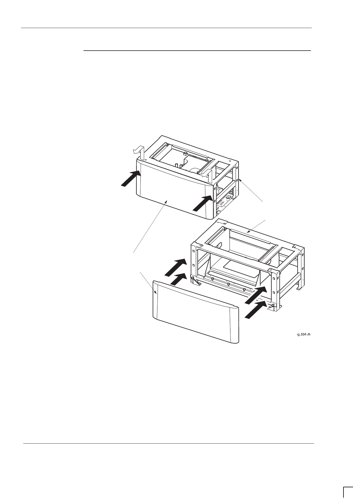
GSM-205-523
Routine maintenance overview
31st Oct 01
Maint. 1–4
Maintenance Information: Horizon
macro
indoor
CONTROLLED INTRODUCTION
68P02902W09-B
Stacking
bracket front
cover removal
and fit
The stacking bracket front cover is attached to the stacking bracket by four
locating clips.
To remove a stacking bracket refer to Figure 1-1 and then remove the stacking
bracket front cover by applying gentle pressure to the outer edges, while easing
the cover up and pulling it away from the bracket.
REMOVAL
FITTING
FRONT
COVER
STACKING
BRACKET
Lift and pull
Apply gentle
pressure
Apply gentle
pressure
ig.334.rh
Figure 1-1 Removing and fitting the stacking bracket front cover
To fit the front cover:
1. Align the four locating clips on the front cover with the four square holes in
the front of the stacking bracket. Ensure that the cut out slot on each clip
is facing downward.
2. Press the cover against the stacking bracket, so that the cut out slot on
each locating clip engages with the bottom edge of each square hole. It
may be necessary to gently push in and down to ensure the cut out slots
are fully engaged and the cover securely in place.

GSM-205-523 6-monthly maintenance procedures
31st Oct 01
Maintenance Information: Horizon
macro
indoor
68P02902W09-B
CONTROLLED INTRODUCTION
Maint. 1–5
6-monthly maintenance procedures
Type of
procedures
The 6-monthly maintenance procedures involve the following:
SCleaning air inlets and exhaust grilles.
SExamining and, if necessary, replacing the optional air filter.
WARNING Potentially lethal voltages and high energy sources are
present in the cabinet when the external ac mains isolator
switch is set to the on position and/or batteries are
connected. Remove rings, watches and jewellery before
starting these procedures, and exercise extreme caution
when working on the equipment.
Cleaning inlets
and exhaust
grilles
CAUTION If the cabinet is operational, this maintenance procedure
should be completed without delay, in order to minimize
duration of air cooling disruption.
Inlets are along the back, sides and front at the base of the cabinet. Air is
expelled through the door vent and through the top panel beneath hood or
stacking bracket.
The following procedure should be followed to clean inlets and exhaust grilles:
SUse vacuum cleaner or brush to ensure bottom inlets are clear of debris.
SOpen door and clean aluminium door vent, taking care to avoid damage.
Replacing the
air filter
Air filters are an option and not essential in a clean environment. The single filter
is mounted under all the fan units. If clogged, fan airflow may be reduced,
straining fan motors and increasing noise.
SIf a filter is fitted, remove two front M6 screws to allow filter holding plate to
drop down. Remove filter, examine and, if dirty, replace with a new filter.
SReplace filter (original or new) then lift up holding plate and secure with
the two M6 screws. Tighten to correct torque (see
Technical Description:
GSM-205-323
Overview and specifications).
SClose and secure the door.

GSM-205-523
12-monthly maintenance procedures
31st Oct 01
Maint. 1–6
Maintenance Information: Horizon
macro
indoor
CONTROLLED INTRODUCTION
68P02902W09-B
12-monthly maintenance procedures
Summary of
12-monthly
procedures
The 12-monthly maintenance procedures involve the following:
S6-monthly procedures.
SChecking and cleaning fans.
SChecking normal operation.
SAnnual check of the installation.
WARNING Potentially lethal voltages and high energy sources are
present in the cabinet when the ac mains isolator switch is
set to the on position and/or batteries are connected.
Remove rings, watches and jewellery before starting these
procedures, and exercise extreme caution when working
on the equipment.
Checking and
cleaning fans
CAUTION If the cabinet is operational, this maintenance procedure
should be completed without delay, in order to minimize
duration of air cooling disruption.
There are three cabinet fan modules, one 4-fan unit and two identical 2-fan
units. Table 1-2 shows the three fan positions.
Table 1-2 Fan positions
Fan
reference Type of module Cabinet position
04-fan unit Right side, beneath digital cage.
12-fan unit Middle, beneath CTUs.
22-fan unit Left side, beneath CTUs.
The fans can be checked and cleaned by the following procedure:
SRemove the fan module by lifting the central slide latch and pulling out.
SUse a brush and vacuum cleaner to remove any dust and dirt on the
module.
SRefit fan and check operation. Any fan not operating should be started by
using the appropriate RESET button.
SObserve the fans through the grilles to ensure correct operation. Listen for
excessive noise. If there is excessive noise, identify fan and replace fan
module (see
Maintenance Information: GSM-205-523
Replacing a fan
module.
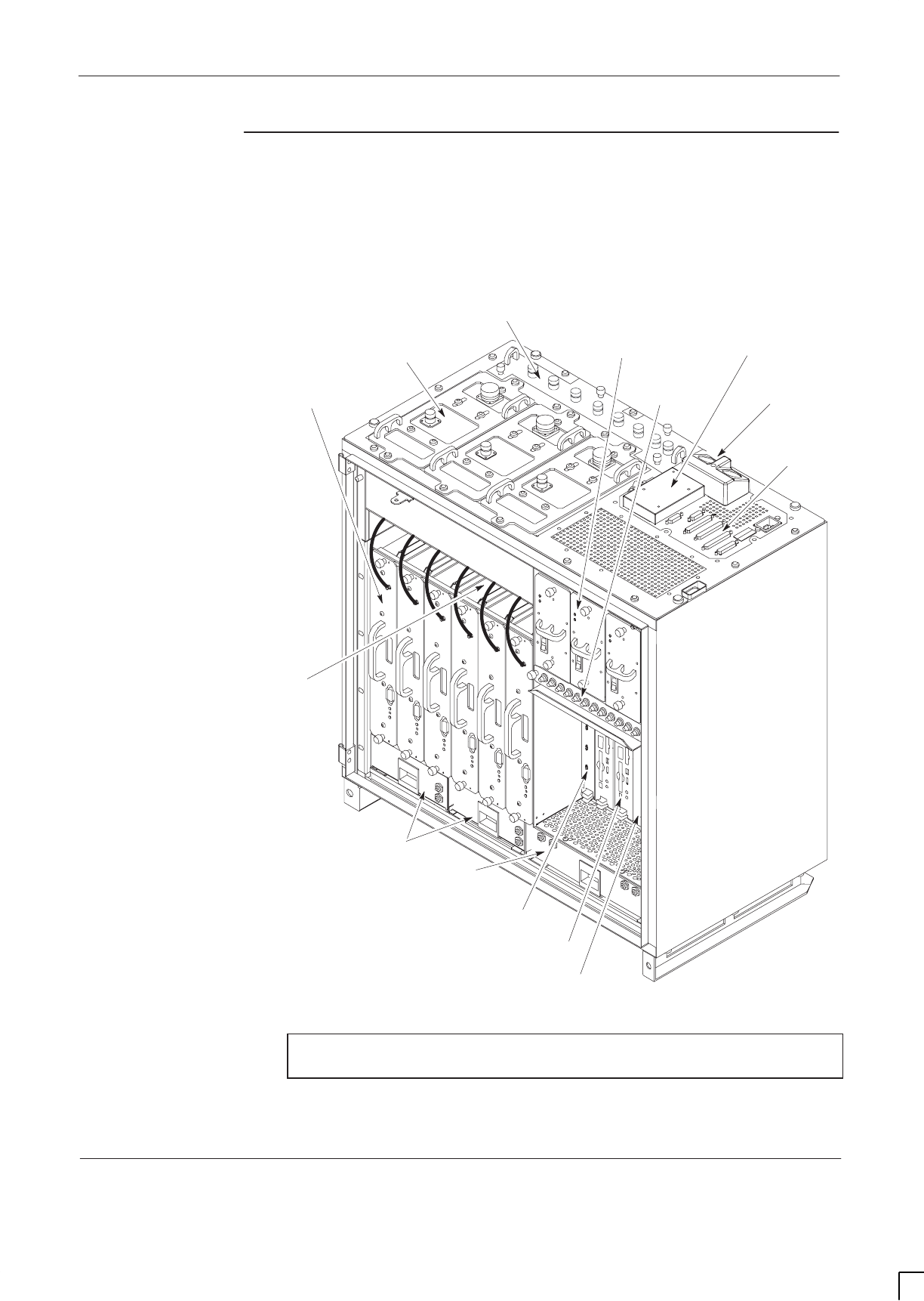
GSM-205-523 12-monthly maintenance procedures
31st Oct 01
Maintenance Information: Horizon
macro
indoor
68P02902W09-B
CONTROLLED INTRODUCTION
Maint. 1–7
Cabinet
modules in
operational
positions
Figure 1-2 shows the cabinet modules, (door and optional hood omitted for
clarity).
CIRCUIT
BREAKER
MODULE (CBM)
T43/BIB
MCUF
ALARM MODULE
FMUX/NIU/BPSM
(NOT VISIBLE)
TWO 2-FAN UNITS
ONE 4-FAN UNIT
SIX TRANSCEIVERS
(CTUs)
THREE Tx BLOCKS
(DCFs SHOWN AS EXAMPLE)
ONE SURF (Rx)
THREE PSMs
(see NOTE)
DC POWER IN
INTERFACE
PANEL
CONNECTORS
HEAT SENSORS
LOCATED ON
BACKPLANE
NOTE An optional hold-up battery module may be installed
instead of a redundant PSM.
Figure 1-2 Cabinet modules with door and hood removed

GSM-205-523
12-monthly maintenance procedures
31st Oct 01
Maint. 1–8
Maintenance Information: Horizon
macro
indoor
CONTROLLED INTRODUCTION
68P02902W09-B
Checking
normal
operation
Check normal operation by visual inspection in the following procedure:
1. Inspect the inside of the cabinet and note any signs of physical damage,
overheating, loose connections, or badly fitting components. Take
appropriate action to correct the damage, and inform the OMC-R.
2. Ensure that the LEDs on modules shown in Table 1-3 are lit, this indicates
correct functioning of the cabinet. If any red LEDs are lit, other than the
door alarm (alarm 3 on the alarm module), inform the OMC-R.
Table 1-3 Normal LED indication of cabinet modules
Equipment with LEDs Colour of LEDs lit
CTUs in locations 0 to 5 Tx status (ORANGE) or
Operational status
(GREEN).
PSMs in locations 0 to 2 Top LED (GREEN).
Digital modules (NIU, MCUF, FMUX,
BPSM) GREEN.
Alarm module 6, 7, 8 GREEN (fans)
3 RED (as door is open)
Annual check of
the installation
NOTE Refer to
Installation and Configuration: (GSM-205-423)
to
carry out the following procedures.
It is recommended the following be performed annually:
SPower down cabinet.
SEarth continuity check.
SPower system insulation check.
SCheck of electricity company connection.
SPre-power up check of supply and earth connection security and
condition.
SPower up of cabinet.
Log the maintenance activity.
After procedures have been completed, restore the cabinet to operational state
and notify the OMC-R of base station availability.

GSM-205-523 24-monthly maintenance procedures
31st Oct 01
Maintenance Information: Horizon
macro
indoor
68P02902W09-B
CONTROLLED INTRODUCTION
Maint. 1–9
24-monthly maintenance procedures
Summary of
24-monthly
procedures
WARNING Potentially lethal voltages and high energy sources are
present in the cabinet when the ac mains isolator switch is
set to the on position and/or batteries are connected.
Remove rings, watches and jewellery before starting these
procedures, and exercise extreme caution when working
on the equipment.
The 24-monthly maintenance procedures involve the following:
S6-monthly procedures.
S12-monthly procedures.
SMechanical inspection of cabinet, including inspection and lubrication of
locks and hinges.

GSM-205-523
24-monthly maintenance procedures
31st Oct 01
Maint. 1–10
Maintenance Information: Horizon
macro
indoor
CONTROLLED INTRODUCTION
68P02902W09-B
Mechanical
inspection of
cabinet, locks
and hinges
The following must be performed every 24 months.
Inspecting the cabinet exterior
NOTE Use a step ladder or platform for access to a stacked
cabinet unit, where necessary.
To inspect the cabinet exterior:
SCheck exterior panels and hood/stacking bracket for dents and structural
damage.
SCheck cabinet top connections for signs of overheating and security of
attachment.
Inspecting the door
To inspect the door:
SCheck cabinet door for distortion, security and correct operation.
SCheck hinges for damage, security and correct operation. Carefully
lubricate the hinges. Ensure that all door seals are wiped clean of the
lubricant.
SCheck earth connection for damage and security.
SCheck door lock mechanism and inspect for ease of operation. Lubricate
the mechanism with light grease. Ensure that lubricated surfaces are
grit-free.
Inspecting the cabinet interior
To inspect the cabinet interior:
SCheck all rack equipment for security of attachment, especially PSM, CBM
and CTU attachment screws using a torxdriver. Tighten to correct torque
(see
Technical Description: GSM-205-323
Overview and specifications).
SCarry out a visual check of all wiring for signs of overheating and security
of attachment.
WARNING Do not overstress the earth connections as this may
damage the connector and reduce the protective function.
SCheck the earth connections for corrosion and tightness using a torque
spanner. Tighten to correct torque (see
Technical Description:
GSM-205-323
Overview and specifications).

31st Oct 01
Maintenance Information: Horizon
macro
indoor
68P02902W09-B
CONTROLLED INTRODUCTION
i
Chapter 2
FRU replacement procedures

GSM-205-523
31st Oct 01
ii
Maintenance Information: Horizon
macro
indoor
CONTROLLED INTRODUCTION
68P02902W09-B

GSM-205-523
31st Oct 01
Maintenance Information: Horizon
macro
indoor
68P02902W09-B
CONTROLLED INTRODUCTION
iii
Chapter 2
FRU replacement procedures i. . . . . . . . . . . . . . . . . . . . . . . . . . . . . . . . . .
Overview of replacement procedures Maint. 2–1. . . . . . . . . . . . . . . . . . . . . . . . . . . . . . . . . . .
Field Replaceable Units (FRUs) Maint. 2–1. . . . . . . . . . . . . . . . . . . . . . . . . . . . . . . . . . .
FRU list Maint. 2–1. . . . . . . . . . . . . . . . . . . . . . . . . . . . . . . . . . . . . . . . . . . . . . . . . . . . . . . .
Torque values Maint. 2–2. . . . . . . . . . . . . . . . . . . . . . . . . . . . . . . . . . . . . . . . . . . . . . . . . .
FRU locations within cabinet Maint. 2–3. . . . . . . . . . . . . . . . . . . . . . . . . . . . . . . . . . . . .
Additional replacement parts Maint. 2–4. . . . . . . . . . . . . . . . . . . . . . . . . . . . . . . . . . . . . . . . . .
Policy on non-FRU parts Maint. 2–4. . . . . . . . . . . . . . . . . . . . . . . . . . . . . . . . . . . . . . . . .
List of non-FRU parts Maint. 2–4. . . . . . . . . . . . . . . . . . . . . . . . . . . . . . . . . . . . . . . . . . . .
Procedure for replacing non-FRU parts Maint. 2–4. . . . . . . . . . . . . . . . . . . . . . . . . . . .
CBIA attachment screws Maint. 2–4. . . . . . . . . . . . . . . . . . . . . . . . . . . . . . . . . . . . . . . . .
Replacing a door Maint. 2–5. . . . . . . . . . . . . . . . . . . . . . . . . . . . . . . . . . . . . . . . . . . . . . . . . . . . .
Introduction to door replacement Maint. 2–5. . . . . . . . . . . . . . . . . . . . . . . . . . . . . . . . . .
Views of door Maint. 2–5. . . . . . . . . . . . . . . . . . . . . . . . . . . . . . . . . . . . . . . . . . . . . . . . . . .
Replacement of door Maint. 2–6. . . . . . . . . . . . . . . . . . . . . . . . . . . . . . . . . . . . . . . . . . . .
Replacing a cabinet heat sensor Maint. 2–7. . . . . . . . . . . . . . . . . . . . . . . . . . . . . . . . . . . . . . .
Overview of heat sensors Maint. 2–7. . . . . . . . . . . . . . . . . . . . . . . . . . . . . . . . . . . . . . . .
Procedure for heat sensor replacement Maint. 2–7. . . . . . . . . . . . . . . . . . . . . . . . . . . .
Replacing a hood Maint. 2–8. . . . . . . . . . . . . . . . . . . . . . . . . . . . . . . . . . . . . . . . . . . . . . . . . . . .
Introduction to hood replacement Maint. 2–8. . . . . . . . . . . . . . . . . . . . . . . . . . . . . . . . .
View of hood Maint. 2–8. . . . . . . . . . . . . . . . . . . . . . . . . . . . . . . . . . . . . . . . . . . . . . . . . . .
Replacing the hood Maint. 2–8. . . . . . . . . . . . . . . . . . . . . . . . . . . . . . . . . . . . . . . . . . . . .
Replacing a stacking bracket Maint. 2–9. . . . . . . . . . . . . . . . . . . . . . . . . . . . . . . . . . . . . . . . . .
View of stacking bracket Maint. 2–9. . . . . . . . . . . . . . . . . . . . . . . . . . . . . . . . . . . . . . . . .
Procedure to replace a stacking bracket Maint. 2–10. . . . . . . . . . . . . . . . . . . . . . . . . . .
Replacing a fan module Maint. 2–11. . . . . . . . . . . . . . . . . . . . . . . . . . . . . . . . . . . . . . . . . . . . . . .
Introduction to fan replacement Maint. 2–11. . . . . . . . . . . . . . . . . . . . . . . . . . . . . . . . . . .
View of fan modules Maint. 2–11. . . . . . . . . . . . . . . . . . . . . . . . . . . . . . . . . . . . . . . . . . . . .
Identifying fan module Maint. 2–12. . . . . . . . . . . . . . . . . . . . . . . . . . . . . . . . . . . . . . . . . . .
Replacing fan modules Maint. 2–12. . . . . . . . . . . . . . . . . . . . . . . . . . . . . . . . . . . . . . . . . .
Replacing a circuit breaker module (CBM) Maint. 2–13. . . . . . . . . . . . . . . . . . . . . . . . . . . . . . .
Preconditions for CBM replacement Maint. 2–13. . . . . . . . . . . . . . . . . . . . . . . . . . . . . . .
Views of CBM Maint. 2–13. . . . . . . . . . . . . . . . . . . . . . . . . . . . . . . . . . . . . . . . . . . . . . . . . .
Replacing a CBM Maint. 2–14. . . . . . . . . . . . . . . . . . . . . . . . . . . . . . . . . . . . . . . . . . . . . . .
Replacing a power supply module (PSM) Maint. 2–15. . . . . . . . . . . . . . . . . . . . . . . . . . . . . . .
Introduction
to PSM replacement Maint. 2–15. . . . . . . . . . . . . . . . . . . . . . . . . . . . . . . . . . . . . . . . . . . .
Preconditions for PSM replacement Maint. 2–15. . . . . . . . . . . . . . . . . . . . . . . . . . . . . . .
View of PSM Maint. 2–15. . . . . . . . . . . . . . . . . . . . . . . . . . . . . . . . . . . . . . . . . . . . . . . . . . .
Replacing a non-redundant PSM Maint. 2–16. . . . . . . . . . . . . . . . . . . . . . . . . . . . . . . . .
Replacing a redundant PSM Maint. 2–16. . . . . . . . . . . . . . . . . . . . . . . . . . . . . . . . . . . . .
Replacing a hold-up battery module Maint. 2–17. . . . . . . . . . . . . . . . . . . . . . . . . . . . . . . . . . . .
To Replace a hold-up battery module Maint. 2–17. . . . . . . . . . . . . . . . . . . . . . . . . . . . . .
Replacing a CTU Maint. 2–19. . . . . . . . . . . . . . . . . . . . . . . . . . . . . . . . . . . . . . . . . . . . . . . . . . . . .
Preconditions for CTU replacement Maint. 2–19. . . . . . . . . . . . . . . . . . . . . . . . . . . . . . .
View of CTU Maint. 2–19. . . . . . . . . . . . . . . . . . . . . . . . . . . . . . . . . . . . . . . . . . . . . . . . . . . .
Replacement procedure for CTU Maint. 2–20. . . . . . . . . . . . . . . . . . . . . . . . . . . . . . . . . .

GSM-205-523
31st Oct 01
iv
Maintenance Information: Horizon
macro
indoor
CONTROLLED INTRODUCTION
68P02902W09-B
Replacing a SURF module Maint. 2–22. . . . . . . . . . . . . . . . . . . . . . . . . . . . . . . . . . . . . . . . . . . .
Preconditions for SURF replacement Maint. 2–22. . . . . . . . . . . . . . . . . . . . . . . . . . . . . .
View of the SURF Maint. 2–22. . . . . . . . . . . . . . . . . . . . . . . . . . . . . . . . . . . . . . . . . . . . . . .
Replacing a SURF module Maint. 2–23. . . . . . . . . . . . . . . . . . . . . . . . . . . . . . . . . . . . . . .
Replacing a Tx block, HCU or plate Maint. 2–25. . . . . . . . . . . . . . . . . . . . . . . . . . . . . . . . . . . .
Introduction to Tx block replacement Maint. 2–25. . . . . . . . . . . . . . . . . . . . . . . . . . . . . .
Views of typical Tx block Maint. 2–26. . . . . . . . . . . . . . . . . . . . . . . . . . . . . . . . . . . . . . . . .
Replacing a Tx block Maint. 2–27. . . . . . . . . . . . . . . . . . . . . . . . . . . . . . . . . . . . . . . . . . . .
Blanking plate, feedthrough plate or HCU replacement Maint. 2–28. . . . . . . . . . . . . .
Replacing a CCB Maint. 2–29. . . . . . . . . . . . . . . . . . . . . . . . . . . . . . . . . . . . . . . . . . . . . . . . . . . .
Overview of CCB replacement Maint. 2–29. . . . . . . . . . . . . . . . . . . . . . . . . . . . . . . . . . . .
View of CCBs in stacking bracket Maint. 2–29. . . . . . . . . . . . . . . . . . . . . . . . . . . . . . . . .
Removing CCBs and CCB control boards Maint. 2–30. . . . . . . . . . . . . . . . . . . . . . . . . .
Fitting replacement CCBs and CCB control boards Maint. 2–31. . . . . . . . . . . . . . . . .
Digital module replacement (MCUF, NIU, FMUX, BPSM, Alarm) Maint. 2–32. . . . . . . . . . . .
Introduction to digital module replacement Maint. 2–32. . . . . . . . . . . . . . . . . . . . . . . . .
Diagram of digital modules Maint. 2–32. . . . . . . . . . . . . . . . . . . . . . . . . . . . . . . . . . . . . . .
Replacing digital modules Maint. 2–33. . . . . . . . . . . . . . . . . . . . . . . . . . . . . . . . . . . . . . . .
Redundant MCUF firmware compatibility Maint. 2–35. . . . . . . . . . . . . . . . . . . . . . . . . . . . . . . .
Overview of MCUF firmware compatibility Maint. 2–35. . . . . . . . . . . . . . . . . . . . . . . . . .
Checking MCUF firmware compatibility Maint. 2–35. . . . . . . . . . . . . . . . . . . . . . . . . . . .
Updating redundant MCUF firmware Maint. 2–35. . . . . . . . . . . . . . . . . . . . . . . . . . . . . .
Testing MCUF redundancy Maint. 2–38. . . . . . . . . . . . . . . . . . . . . . . . . . . . . . . . . . . . . . .

GSM-205-523 Overview of replacement procedures
31st Oct 01
Maintenance Information: Horizon
macro
indoor
68P02902W09-B
CONTROLLED INTRODUCTION
Maint. 2–1
Overview of replacement procedures
Field
Replaceable
Units (FRUs)
WARNING Potentially lethal voltages and high energy sources are
present in the cabinet when the external isolator switch is
set to the on position and/or batteries are connected.
Remove rings, watches and jewellery before starting these
procedures, and exercise extreme caution when working
on the equipment.
Maintenance procedures on this equipment must only be
carried out by suitably qualified personnel.
This chapter provides information on replacement of field replaceable units
(FRUs). Only components classed as FRUs are detailed in this chapter.
Any requirement to open or close a door, or remove and replace the optional
hood, is assumed in procedures. Shutting the door, or replacing the hood is
assumed at the end of any procedure. SURF module and Tx block replacement
may be carried out with the stacking bracket in place, but the CCB basket (if
fitted) must be removed, (see Replacing a CCB ). For door opening, or hood or
stacking bracket removal, see Routine maintenance overview.
Where customers wish to perform a minor repair on an FRU, in order to save the
cost of full replacement, they should consult Motorola for more detailed
procedures or replacement components (see Additional replacement parts).
FRU list
The following is a list of FRUs used in this equipment:
SDoor.
SHeat sensor modules.
SHood.
SStacking bracket.
SFan units.
SCircuit breaker module (CBM).
SPower supply module (PSM).
SHold-up battery module.
SCTU.
STx blocks, including feedthrough plate.
SSURF module.
SCCBs (installed in stacking bracket basket as CCB FRU).
SDigital modules (MCUFs, NIUs, FMUXs, alarm board and BPSMs).

GSM-205-523
Overview of replacement procedures
31st Oct 01
Maint. 2–2
Maintenance Information: Horizon
macro
indoor
CONTROLLED INTRODUCTION
68P02902W09-B
Torque values
Table 2-1 details torque values used during repair procedures.
Table 2-1 Torque values for all cabinet screws/bolts and RF connectors
Size of
screw/bolt M4 M6 M8 M10 SMA N-type 7/16
Torque value 2.2 Nm 3.4 Nm 5 Nm 10 Nm 1 Nm 3.4 Nm 25 Nm
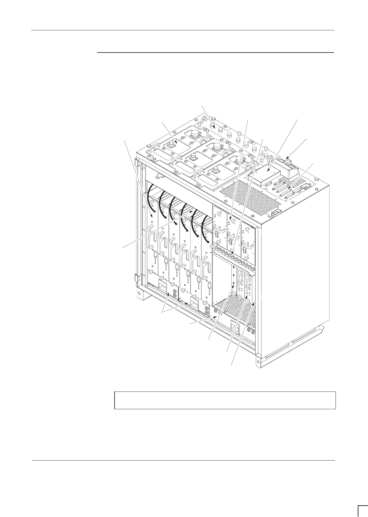
GSM-205-523 Overview of replacement procedures
31st Oct 01
Maintenance Information: Horizon
macro
indoor
68P02902W09-B
CONTROLLED INTRODUCTION
Maint. 2–3
FRU locations
within cabinet
Figure 2-1 shows a cabinet with FRUs identified. Door, optional hood, stacking
bracket and CCBs are shown in the relevant FRU sections.
CIRCUIT
BREAKER
MODULE (CBM)
T43/BIB
MCUF
ALARM MODULE
FMUX/NIU/BPSM
(NOT VISIBLE)
TWO 2-FAN UNITS
ONE 4-FAN UNIT
SIX TRANSCEIVERS
(CTUs)
THREE Tx BLOCKS
(DCFs SHOWN AS EXAMPLE)
ONE SURF (Rx)
THREE PSMs
(see NOTE)
DC POWER IN
INTERFACE
PANEL
CONNECTORS
HEAT SENSORS
LOCATED ON
BACKPLANE
NOTE An optional hold-up battery module may be installed
instead of a redundant PSM.
Figure 2-1 Cabinet, without door or hood, showing FRU components

GSM-205-523
Additional replacement parts
31st Oct 01
Maint. 2–4
Maintenance Information: Horizon
macro
indoor
CONTROLLED INTRODUCTION
68P02902W09-B
Additional replacement parts
Policy on
non-FRU parts
Non-FRU parts are:
SItems unlikely to fail, but replacement of which is essential if failure occurs.
or
SSubsections of FRUs, where local conditions may make it more
economical to repair the FRU.
CAUTION Only qualified personnel should attempt non-FRU
replacement, in order to minimize risk of equipment
damage. For example, the CBIA main cage requires care
in removal and installation, and Individual fans require
care in ensuring correct direction of airflow.
List of non-FRU
parts
Non-FRU parts include the following:
SDoor lock.
SIndividual fans within a fan module.
SAny part of the CBIA: main cage, harness, door sensor, interface panel,
or backplane.
Procedure for
replacing
non-FRU parts
Customers requiring non-FRU replacement should:
1. Contact the local Motorola office for availability.
2. Seek Motorola advice for fitting non-FRU parts.
CBIA
attachment
screws
The CBIA is attached to the cabinet by screws which should not be loosened:
SSeven M4 screws to SURF harness (two guide pins lock cage into
position).
SFour M6 (left side) and five M6 (right side) screws at cabinet front.
SEight M6 T30 screws for interface panel attachment to top panel.
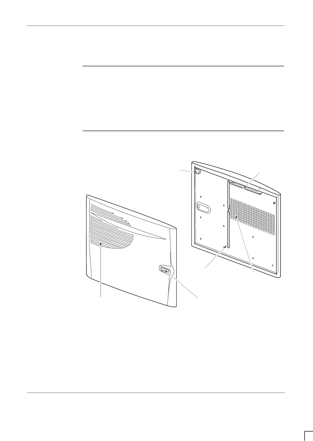
GSM-205-523 Replacing a door
31st Oct 01
Maintenance Information: Horizon
macro
indoor
68P02902W09-B
CONTROLLED INTRODUCTION
Maint. 2–5
Replacing a door
Introduction to
door
replacement
The door is essential to the correct operation of the ventilation system. The door
also provides protection to equipment inside. For these reasons, the
replacement procedure should be completed in one session, and the cabinet
then secured.
Views of door
Figure 2-2 shows an inside and outside view of the door.
ig.266.rh
VENTILATION
GRID
EXTERNAL VIEW
TRIGGER
LATCH
INTERNAL VIEW
VERTICAL AIR
BAFFLE
DOOR ALARM
BRACKET
HONEYCOMB
VENTILATION
DOOR STOP
BRACKET
Figure 2-2 Inside and outside views of door

GSM-205-523
Replacing a door
31st Oct 01
Maint. 2–6
Maintenance Information: Horizon
macro
indoor
CONTROLLED INTRODUCTION
68P02902W09-B
Replacement of
door
Removing a faulty door
To remove a door, open and:
1. At the cabinet, unscrew M6 nut, holding the door earth cable to the
cabinet. Retain nut for re-use.
2. Unscrew M6 holding screw on slide arm several turns, then unhook slide
arm from the cabinet attachment point by lifting up.
3. Move door to about 90°and lift door off hinges.
Fitting a replacement door
CAUTION Avoid damaging the honeycomb door vent.
To install a replacement door:
1. Hold door at about 90°and lift onto door hinges.
2. Attach the door earth cable to the cabinet by using the M6 nut. Tighten to
the correct torque (see Overview of replacement procedures).
3. Place the slide arm onto the cabinet attachment holding point and apply
several turns of the M6 holding screw.

GSM-205-523 Replacing a cabinet heat sensor
31st Oct 01
Maintenance Information: Horizon
macro
indoor
68P02902W09-B
CONTROLLED INTRODUCTION
Maint. 2–7
Replacing a cabinet heat sensor
Overview of
heat sensors
Heat sensors plug into the backplane from the front above the CTUs. Each one
can be separately detached, and a replacement inserted. CTUs are removed to
gain access for this procedure.
There is one 70 _C sensor and two 85 _C sensors. Each sensor is marked with
the appropriate temperature.
Procedure for
heat sensor
replacement
To replace heat sensors:
WARNING Before disconnecting RF cables, ensure that the RF
power is OFF by turning cabinet PSMs off. If RF power is
ON when cables are disconnected, severe burns may
result.
1. Remove the CTUs (see Replacing a CTU).
2. Identify the faulty heat sensor.
3. Remove the faulty heat sensor by pulling.
4. Install the replacement heat sensor by pushing firmly into place.
5. Install the CTUs (see Replacing a CTU).
The heat sensors should now be operational.
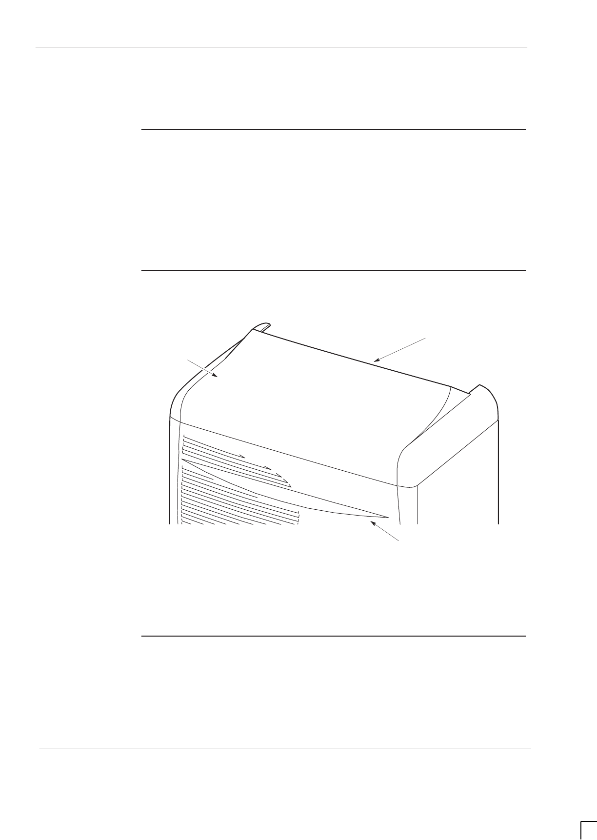
GSM-205-523
Replacing a hood
31st Oct 01
Maint. 2–8
Maintenance Information: Horizon
macro
indoor
CONTROLLED INTRODUCTION
68P02902W09-B
Replacing a hood
Introduction to
hood
replacement
This procedure assumes an optional hood is already fitted, with hood pins
located in the correct cabinet locations. If the hood is to replace a stacking
bracket, refer to the appropriate procedures in this chapter Replacing a
stacking bracket and
Installation and Configuration: (GSM number)
Chapter 2,
Hood or stacking bracket fit.
View of hood
Figure 2-3 shows a top view of the hood.
ig.333.rh
LIFTING EDGE
HOOD
TOP SECTION OF
CABINET DOOR
Figure 2-3 Hood view when placed on top of cabinet
Replacing the
hood
The hood is held in place by four pins. Remove the faulty hood by lifting the
edge, until free of the pins.
To fit the replacement hood, first align the hood to the back pins, then lower the
hood onto the pins and press firmly into place.
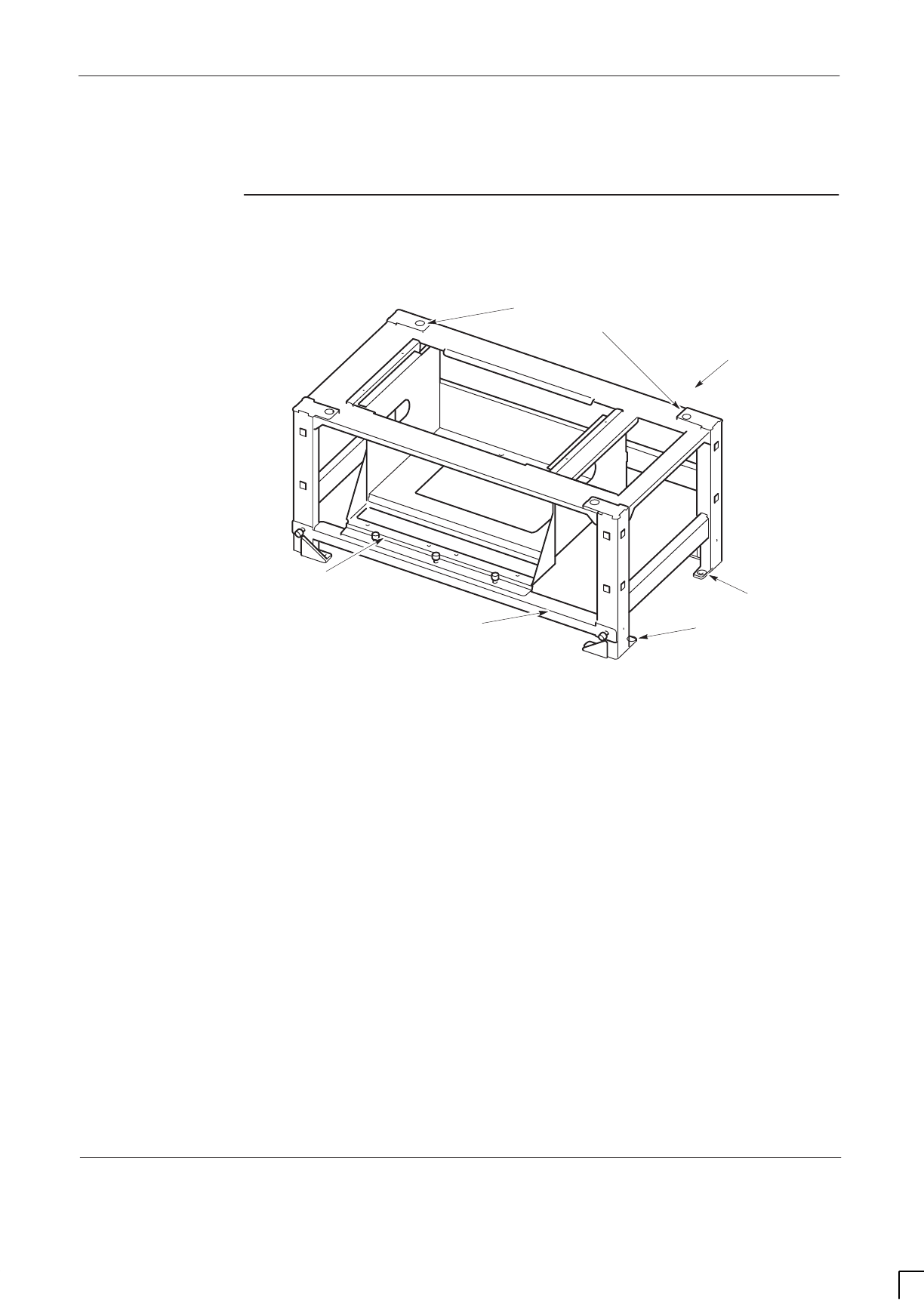
GSM-205-523 Replacing a stacking bracket
31st Oct 01
Maintenance Information: Horizon
macro
indoor
68P02902W09-B
CONTROLLED INTRODUCTION
Maint. 2–9
Replacing a stacking bracket
View of stacking
bracket
Figure 2-4 shows a stacking bracket with optional CCB basket.
ig.268.rh
M8 HOLES (8) FOR
BOTTOM CABINET
ATTACHMENT.
M10 HOLES (4) FOR TOP CABINET
ATTACHMENT (IF REQUIRED)
CCB BASKET
(IF REQUIRED)
DETACHABLE
CCB BASKET BAR
REAR OF
BRACKET
Figure 2-4 Stacking bracket view with optional CCB basket

GSM-205-523
Replacing a stacking bracket
31st Oct 01
Maint. 2–10
Maintenance Information: Horizon
macro
indoor
CONTROLLED INTRODUCTION
68P02902W09-B
Procedure to
replace a
stacking
bracket
Replace the stacking bracket as follows:
1. Remove the front cover by pulling away.
WARNING The cabinet can weigh as much as 115 kg with the hood
fitted. Observe correct lifting precautions.
2. If an upper cabinet is fitted on top of stacking bracket, decommission the
cabinet as described in
Installation and Configuration: (GSM-205-423)
Chapter 4 Decommissioning Horizon
macro
indoor.
3. If a CCB is fitted, remove it (see Replacing a CCB).
4. Loosen and remove the eight M8 screws holding the faulty bracket.
WARNING The stacking bracket can weigh as much as 15 kg (more if
CCB is contained in CCB basket). Observe the correct
lifting precautions.
5. Lift the faulty stacking bracket off the cabinet.
6. Align the replacement stacking bracket onto the cabinet, and fit the eight
M8 screws. Tighten to correct torque (see Overview of replacement
procedures).
7. Install and commission any upper cabinet removed in step 2 as described
in
Installation and Configuration: (GSM-205-423)
Chapter 2 and Chapter
3.
8. Refit the front cover by attaching to side lugs and pushing into position.
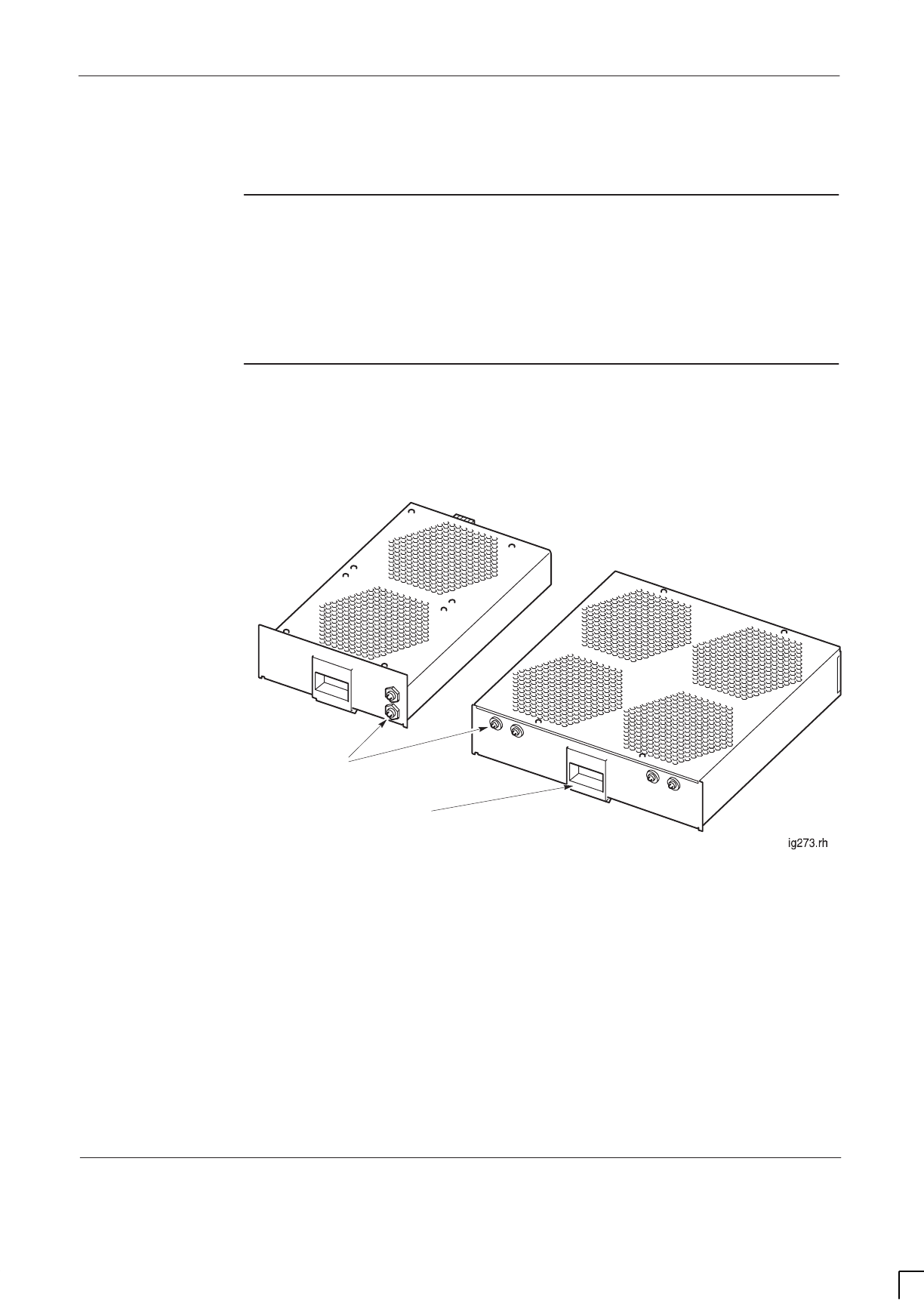
GSM-205-523 Replacing a fan module
31st Oct 01
Maintenance Information: Horizon
macro
indoor
68P02902W09-B
CONTROLLED INTRODUCTION
Maint. 2–11
Replacing a fan module
Introduction to
fan replacement
The fan modules can be replaced while the cabinet is operational, but be aware
that airflow is reduced while fans are out of service, and while door is open. This
will raise equipment temperature, and could shut down the cabinet by triggering
the heat sensors.
View of fan
modules
Figure 2-5 shows a view of the two types of fan module fitted in a Horizon
macro
cabinet, with reset buttons indicated.
RESET BUTTONS
(ONE PER FAN)
2-FAN
UNIT
4-FAN
UNIT
SLIDE LATCH FOR
MODULE REMOVAL
Figure 2-5 View of fan modules

GSM-205-523
Replacing a fan module
31st Oct 01
Maint. 2–12
Maintenance Information: Horizon
macro
indoor
CONTROLLED INTRODUCTION
68P02902W09-B
Identifying fan
module
There are three cabinet fan modules, one 4-fan unit and two identical 2-fan
modules. Table 2-2 shows the three fan positions.
Table 2-2 Fan positions
Fan
reference Type of module Cabinet position
04-fan unit Right side, underneath digital cage.
12-fan unit Middle, beneath CTUs.
22-fan unit Left side, beneath CTUs.
Replacing fan
modules
CAUTION If the cabinet is operational, this replacement procedure
should be completed without delay to minimize the
duration of air cooling disruption.
To replace the fan:
1. Lift the central slide latch.
2. Pull out the fan module.
3. Insert the replacement module firmly in place, ensuring the slide latch has
engaged.
4. Ensure all fans are operating. Any fan not operating should be started by
using the appropriate RESET button.
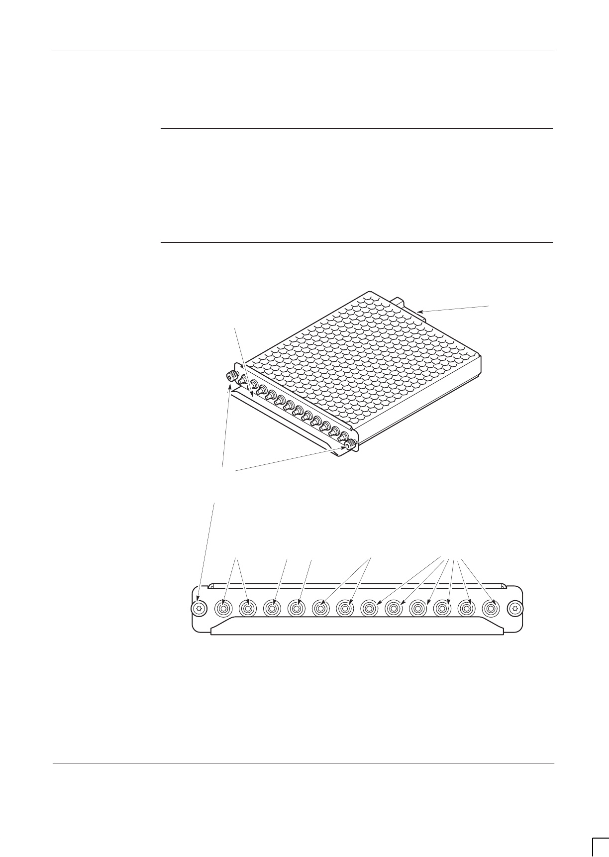
GSM-205-523 Replacing a circuit breaker module (CBM)
31st Oct 01
Maintenance Information: Horizon
macro
indoor
68P02902W09-B
CONTROLLED INTRODUCTION
Maint. 2–13
Replacing a circuit breaker module (CBM)
Preconditions
for CBM
replacement
The CBM controls power for the whole of the cabinet, apart from the PSMs.
Consequently, the replacement of a CBM can only take place after the cabinet
has been taken out of service and isolated, in agreement with the OMC-R.
Views of CBM
Figure 2-6 shows views of the CBM with circuit breaker buttons identified.
FRONT VIEW ig.281.rh
6 CTUs (0 TO 5)
12 A2 A4 A 7 A
BACKPLANE CONNECTOR
M4 MODULE ATTACHMENT
SCREWS
CCB (0 AND 1) SURF FANS BPSMs (A AND B)
7 A
HANDLE-BAFFLE
Figure 2-6 Views of CBM with circuit breaker buttons identified

GSM-205-523
Replacing a circuit breaker module (CBM)
31st Oct 01
Maint. 2–14
Maintenance Information: Horizon
macro
indoor
CONTROLLED INTRODUCTION
68P02902W09-B
Replacing a
CBM
To replace a CBM:
1. Verify that the power source isolator is switched to OFF, and locked (if
possible).
2. Set the switch of each PSM to the OUTPUT DISABLE position.
3. Unscrew both CBM module attachment screws (shown in Figure 2-6),
using a torxdriver.
4. Pull out module, using handle-baffle.
5. Press and release all push on/push off circuit breaker buttons of the new
CBM module into the out (off) position.
6. Insert the replacement module and press firmly into place.
7. Tighten both module attachment screws to correct torque (see Overview
of replacement procedures), using an M4 Torx driver.
To restore power to the cabinet:
1. Switch on the external power supply to the cabinet.
2. Turn each PSM switch to the OUTPUT ENABLE position. Check that each
PSM has the ACTIVE (green) light on and the ALARM (red) light off.
3. Press the CBM isolator marked FANS. Check that each fan, eight in total,
is operating correctly. Any fan not started may be activated by the reset
button (marked either FRONT or REAR) on the appropriate fan unit.
4. Press the CBM circuit breaker button marked BPSM A and (if redundant
BPSM fitted) BPSM B. Check all associated digital module indicators
operate correctly.
5. Press the CBM circuit breaker button marked SURF, and if CCBs fitted the
circuit breaker buttons marked CCB0 and CCB1.
6. Press the appropriate CBM circuit breaker buttons for the CTUs fitted, and
check that the LEDs for each CTU indicate correct operation.
7. Close the door to ensure correct ventilation.
This completes the CBM replacement and power up sequence for a cabinet.
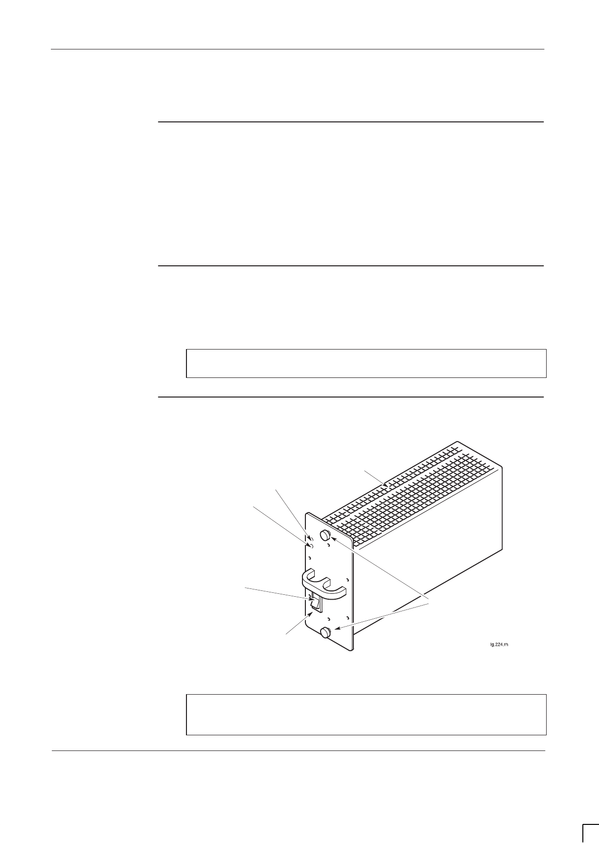
GSM-205-523 Replacing a power supply module (PSM)
31st Oct 01
Maintenance Information: Horizon
macro
indoor
68P02902W09-B
CONTROLLED INTRODUCTION
Maint. 2–15
Replacing a power supply module (PSM)
Introduction
to PSM
replacement
There are three slots for PSMs. A single PSM can power a cabinet containing
up to three CTUs therefore, a cabinet populated with six CTUs only requires two
PSMs to be fully operational. The third slot can be used for an additional power
supply to provide redundancy, or for the hold-up battery unit. A replacement
PSM can be inserted into a vacant slot without powering down, thereby avoiding
any need to take the cabinet out of service.
Preconditions
for PSM
replacement
Replacement PSM must be of appropriate type for the cabinet (+ 27 V dc,
–48/60 V dc, or 100/240 V ac).
CAUTION Replacement PSM must have the correct input voltage
rating for the cabinet.
View of PSM
Figure 2-7 shows a view of the PSM with key features identified.
PSM FRONT PANEL
AIR VENTS ON
ENTIRE TOP AND
BOTTOM PANELS
GREEN LED
ACTIVE
RED LED
ALARM
OUTPUT DISABLE
SWITCH
M4 MODULE ATTACHMENT
SCREWS
Figure 2-7 View of PSM with key features identified
NOTE There are several manufacturers of the PSMs. All PSMs of
the same type are fully compatible with each other,
regardless of manufacturer.

GSM-205-523
Replacing a power supply module (PSM)
31st Oct 01
Maint. 2–16
Maintenance Information: Horizon
macro
indoor
CONTROLLED INTRODUCTION
68P02902W09-B
Replacing a
non-redundant
PSM
The following procedure should be followed if there are one or two PSMs fitted
in the cabinet. To replace a non-redundant PSM:
1. Set the switch of the replacement PSM to OUTPUT DISABLE.
2. Remove the blanking assembly of spare slot, if fitted, by unscrewing the
attachment screws with a torxdriver.
3. Remove the hold-up battery module, if fitted, as described in Replacing a
hold-up battery module.
4. Insert the replacement PSM in resulting or spare slot, and tighten both
module attachment screws to the correct torque (see Overview of
replacement procedures), using a torxdriver.
5. Set the replacement PSM switch to OUTPUT ENABLE. Check that the
ACTIVE LED (green) is lit.
6. Set switch of faulty PSM to OUTPUT DISABLE. The ACTIVE LED will
extinguish (the ACTIVE LED may already be off if a fault has resulted in
output failure of that PSM). The ALARM LED (red) will light, or if already lit
due to alarm state, will stay on.
7. Unscrew the faulty PSM module attachment screws using an M4
torxdriver, and remove the module. The ALARM LED will extinguish.
8. If removed in step 3, refit hold-up battery module as described in
Replacing a hold-up battery module.
9. Fit the cover plate in the vacated PSM position, if required, by tightening
the attachment screws to the correct torque with a torxdriver, as stated in
step 4.
Replacing a
redundant PSM
The following procedure should be followed if there are three PSMs fitted. To
replace a redundant PSM:
1. Set the switch of replacement PSM to OUTPUT DISABLE.
2. Set switch of faulty PSM to OUTPUT DISABLE. The ACTIVE (green) LED
will extinguish (the ACTIVE LED may already be off, if a fault has resulted
in output failure of that PSM). The ALARM LED (red) will light, or if already
lit due to alarm state, will stay on.
3. Unscrew the module attachment screws by M4 torxdriver, and remove the
module. The ALARM LED will extinguish.
4. Insert the replacement PSM, and tighten both module attachment screws
to the correct torque (see Overview of replacement procedures), using
a torxdriver
5. Set switch to OUTPUT ENABLE. Check the ACTIVE LED is lit.

GSM-205-523 Replacing a hold-up battery module
31st Oct 01
Maintenance Information: Horizon
macro
indoor
68P02902W09-B
CONTROLLED INTRODUCTION
Maint. 2–17
Replacing a hold-up battery module
To Replace a
hold-up battery
module
WARNING The batteries are capable of supplying high short circuit
currents and as such provides a high energy hazard.
To replace a hold-up battery module:
1. Verify that the enable switch of the replacement hold-up battery module is
set to O.
2. Cut the cable tie that secures the jumper lead to the isolation connection
access hatch. Open the access hatch by turning the fastener a quarter
turn anticlockwise and lifting.
3. Fit the jumper lead between the battery spade terminals as shown in
Figure 2-8. Close the access hatch and turn the fastener a quarter turn
clockwise to secure.
4. Set the enable switch of the faulty hold-up battery module to O (off). The
ACTIVE LED (green) will extinguish (the green LED may already be off, if
a fault has resulted in output failure). The ALARM LED (red) will light, or if
already lit due to alarm state, will stay on.
WARNING The hold-up battery module weighs 5.9 kg. Handle with
care.
5. Unscrew the module attachment screws using a torxdriver, and remove
the module. The red LED will go off.
6. Insert the replacement hold-up battery module.
7. Ensure the replacement hold-up battery module is firmly in position and
tighten both module attachment screws using a torxdriver. Tighten to a
torque of 2.2 Nm.
8. Set the hold-up battery module enable switch to I (on). Check that the
CHARGE LED (green) is lit.
NOTE The ACTIVE LED (green) will not light until 1.5 to 2 hours
after installation. The ALARM LED (red) may also be lit if
the initial battery voltage is below 19 V dc (+/–0.25 V).
9. Remove the battery isolation jumper lead from the faulty hold-up battery
module and secure it to the outside of the access hatch before
transportation.
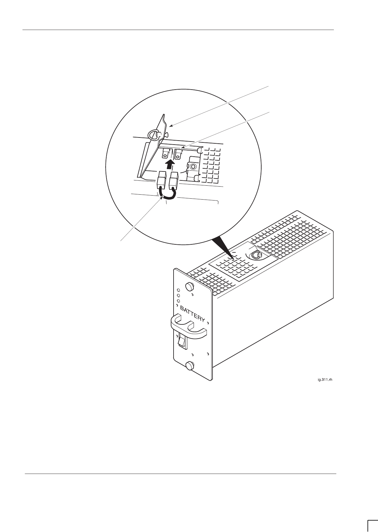
GSM-205-523
Replacing a hold-up battery module
31st Oct 01
Maint. 2–18
Maintenance Information: Horizon
macro
indoor
CONTROLLED INTRODUCTION
68P02902W09-B
Figure 2-8 shows the battery hold-up with the battery isolation jumper
connection shown in detail.
ACCESS HATCH
BATTERY SPADE
CONNECTORS
JUMPER LEAD
Figure 2-8 Connecting battery isolation jumper lead
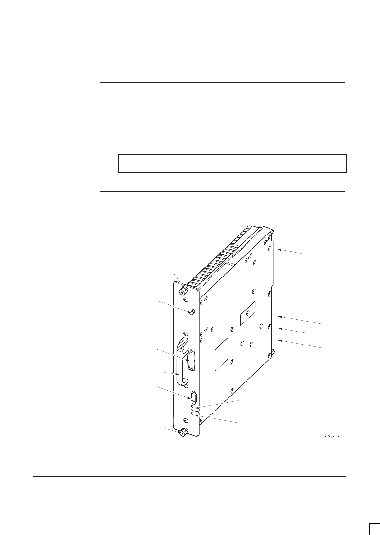
GSM-205-523 Replacing a CTU
31st Oct 01
Maintenance Information: Horizon
macro
indoor
68P02902W09-B
CONTROLLED INTRODUCTION
Maint. 2–19
Replacing a CTU
Preconditions
for CTU
replacement
There are up to six CTUs in a cabinet. Replacing a CTU requires removal of RF
transmitter power for that CTU; it is therefore advisable to perform this
procedure during periods of low traffic. The OMC-R should be notified of
imminent repair activity.
NOTE The CTU replacement procedure is the same for all CTUs,
regardless of frequency rating.
View of CTU
Figure 2-9 shows a view of a CTU with key features identified.
Tx OUT
CONNECTOR
Tx STATUS LED
HANDLE
M4 MODULE ATTACHMENT
SCREW
M4 MODULE ATTACHMENT
SCREW
TTY INTERFACE
CONTROL
PROCESSOR
TEST INTERFACE
RADIO STATUS LED
RECESSED MANUAL
RESET BUTTON (if fitted)
Rx A
Rx B
LOOPBACK
TEST PORT (L)
BACKPLANE POWER AND
SIGNAL CONNECTOR
Figure 2-9 CTU view with key features

GSM-205-523
Replacing a CTU
31st Oct 01
Maint. 2–20
Maintenance Information: Horizon
macro
indoor
CONTROLLED INTRODUCTION
68P02902W09-B
Replacement
procedure for
CTU
CAUTION An earthing wrist strap must be worn when handling
CTUs. An ESP earthing connection point is provided
above the leftmost PSM.
Removing a faulty CTU
To remove a CTU:
1. Locate the CTU to be replaced. CTUs are sequentially numbered, with
CTU 0 on the right, and CTU 5 on the left, as shown in Figure 2-1.
2. Disable the CTU transmit RF power by using the shutdown_device
command at the OMC-R or from a PC connected to the MCUF.
NOTE Refer to
Technical Description: BSS Command Reference
(GSM-100-321)
for information on usage and specific
commands.
3. When the CTU has been shutdown, check the Tx STATUS LED (solid
yellow) is extinguished.
4. Press and release the appropriate CTU circuit breaker button on the CBM
to the out (off) position. Ensure the RADIO STATUS LED is extinguished.
WARNING Ensure that RF power is OFF, before disconnecting RF
cables. Severe burns may result if RF power is ON when
cables are disconnected.
5. Unscrew the coaxial cable from the Tx OUT SMA connector at the top of
the CTU front panel.
6. Unscrew the two CTU attachment screws using M4 Torx driver.
WARNING The CTU weighs 5 kg. Handle with care.
CAUTION Take care to avoid damage of CTU rear connectors when
handling outside of the cabinet.
7. Withdraw the CTU using the handle. Support the unit from underneath as
it slides out.

GSM-205-523 Replacing a CTU
31st Oct 01
Maintenance Information: Horizon
macro
indoor
68P02902W09-B
CONTROLLED INTRODUCTION
Maint. 2–21
Fitting replacement CTU
To fit a replacement CTU:
1. Ensure that the correct CTU push-on/push-off circuit breaker button on the
CBM has been pressed to the out (off) position.
2. Ensure that the transmit RF power of the correct CTU has been locked
using the shutdown_device command at the OMC-R or from a PC
connected to the MCUF.
3. Insert replacement CTU module, taking care to locate the module on the
guide rails. Press firmly into place.
4. Tighten both module attachment screws to the correct torque (see
Overview of replacement procedures), using an M4 Torx driver.
5. Attach coax cable to appropriate Tx block or feedthrough plate for the
CTU. Tighten to correct torque (see Overview of replacement
procedures).
NOTE The Tx cable has a 90° SMA connector at one end, and a
straight SMA connector at the other end. The 90° end is
designed for connection to the Tx port of a CTU.
6. Screw the coaxial cable onto the Tx OUT SMA connector at the top of the
CTU front panel. Tighten to correct torque (see Overview of replacement
procedures).
7. Press and release the appropriate CTU circuit breaker button on the CBM.
The RADIO STATUS LED will flash green for about two minutes, and then
remain lit.
CAUTION If both RADIO STATUS and Tx STATUS LEDs are
flashing, the bootcode is downloading into non-volatile
memory for software upgrade. Power should not be
removed, nor the cabinet reset, until downloading has
been completed, as this will corrupt the non-volatile
memory. If bootcode is corrupted, contact Motorola
Customer Network Resolution Centre requesting the
bootcode restoration procedure and the appropriate
bootcode file.
8. Enable the CTU transmit RF power by using the ins_device command
at the OMC-R or from a PC connected to the MCUF. The Tx STATUS LED
(yellow) will be lit if the CTU is transmitting.
9. Notify the OMC-R of base station availability and log the maintenance
activity.
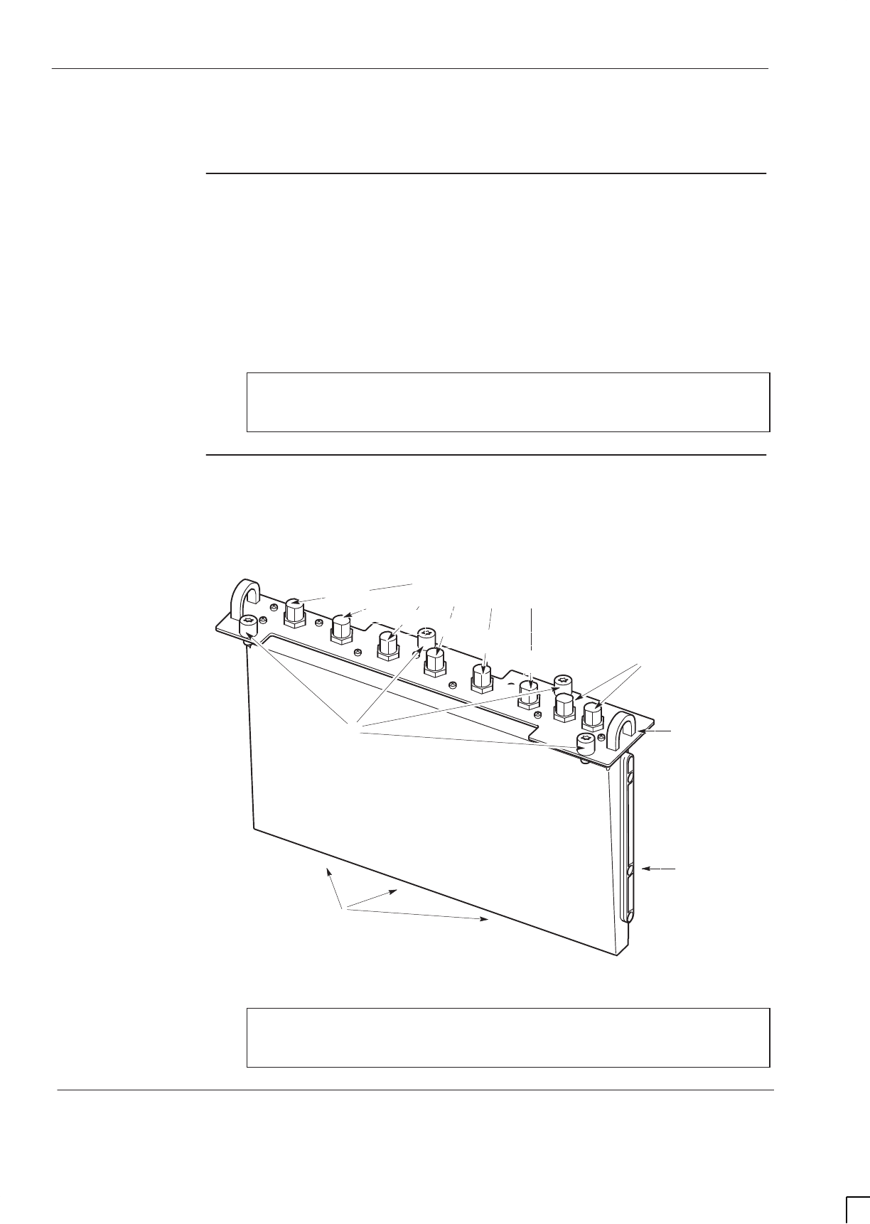
GSM-205-523
Replacing a SURF module
31st Oct 01
Maint. 2–22
Maintenance Information: Horizon
macro
indoor
CONTROLLED INTRODUCTION
68P02902W09-B
Replacing a SURF module
Preconditions
for SURF
replacement
The cabinet only has one SURF module, either a dual band or a single band
SURF. Consequently, the replacement of a SURF module can only take place
after the cabinet has been taken out of service, in agreement with the OMC-R.
If a stacking bracket is fitted with a CCB basket, the CCB basket has to be
removed in order to gain access to the SURF module. To remove CCB basket
see Replacing a CCB.
CAUTION An earthing wrist strap must be worn when handling SURF
modules. An ESP earthing connection point is provided
above the leftmost PSM.
View of the
SURF
Figure 2-10 shows a single band SURF module. Where RXn appears in
Figure 2-10, the n may be 850, 900, 1800 or 1900, depending on the frequency
of the SURF module.
RXn
1B
RXn
2B
GUIDE RAIL FOR
INSERTION
SIX N-TYPE RECEIVE ANTENNA CONNECTIONS
(2 PER DLNB EQUIVALENT)
EXTENSION PORTS TO
OTHER CABINETS
3 CONNECTORS ON UNDERSIDE
TO SURF HARNESS
HANDLE FOR
MODULE
REMOVAL
FOUR M6 MODULE
ATTACHMENT
SCREWS
RXn
0A
RXn
1A
2A
RXn
RXn
0B
Single band SURF
Figure 2-10 View of a single band SURF module
NOTE The dual band SURF replacement procedure is almost
identical, with the addition of the extra two second
frequency antenna connections.

GSM-205-523 Replacing a SURF module
31st Oct 01
Maintenance Information: Horizon
macro
indoor
68P02902W09-B
CONTROLLED INTRODUCTION
Maint. 2–23
Replacing a
SURF module
Removing a faulty SURF module
To remove a SURF:
NOTE The procedure for replacing a faulty SURF module is the
same for both single and dual band SURF variants.
1. Note the RF cable connections to the SURF module to enable correct
reconnection to the replacement module.
WARNING Before disconnecting RF cables, ensure that RF power is
OFF. If RF power is ON when cables are disconnected,
severe burns may result.
2. Disable all CTU transmit RF power by using the shutdown_device
command at the OMC-R or from a PC connected to the MCUF.
NOTE Refer to
Technical Description: BSS Command Reference
(GSM-100-321)
for information on usage and specific
device codes.
3. When all CTUs have been shutdown, check that the Tx STATUS LED
(yellow) is extinguished.
4. Press and release the CTU circuit breaker buttons on the CBM to the out
(off) position. Ensure each RADIO STATUS LED is extinguished.
5. Press and release the SURF circuit breaker button on the CBM to the out
(off) position.
6. Disconnect the coaxial RF cables by carefully unscrewing and pulling
them out of the module sockets. Note the positions for correct
replacement.
7. Using a torxdriver, unscrew the four M6 torx captive screws holding the
SURF module to the top of the cabinet.
8. Using the handles, lift the SURF block from the slot.

GSM-205-523
Replacing a SURF module
31st Oct 01
Maint. 2–24
Maintenance Information: Horizon
macro
indoor
CONTROLLED INTRODUCTION
68P02902W09-B
Fitting a replacement SURF module
To fit a replacement SURF:
1. Transfer the protective caps on the RF connectors from the replacement
module to the faulty module.
2. Insert the replacement SURF module firmly into place. Take care to avoid
trapping cables as the module is seated.
3. Tighten the four captive M6 torx screws to correct torque (see Overview
of replacement procedures).
4. Reconnect the coaxial RF cables to the positions noted in the removal
procedure. Tighten to correct torque (see Overview of replacement
procedures).
5. Reset the SURF circuit breaker button on the CBM.
6. Reset the CTU circuit breaker buttons on the CBM. Each RADIO STATUS
LED will flash green for about two minutes, and then remain lit.
7. Enable the CTU transmit RF power by using the ins_device command
at the OMC-R or from a PC connected to the MCUF. The Tx STATUS LED
(yellow) will be lit if the CTU is transmitting.
8. Notify the OMC-R of base station availability and log the maintenance
activity.
The SURF module replacement is now complete.

GSM-205-523 Replacing a Tx block, HCU or plate
31st Oct 01
Maintenance Information: Horizon
macro
indoor
68P02902W09-B
CONTROLLED INTRODUCTION
Maint. 2–25
Replacing a Tx block, HCU or plate
Introduction to
Tx block
replacement
WARNING Ensure that RF power is OFF, before disconnecting RF
cables. Severe burns may result if RF power is ON when
RF cables are disconnected.
CAUTION An earthing wrist strap must be worn when handling Tx
blocks. An ESP earthing connection point is provided
above the leftmost PSM.
There are three slots for Tx blocks in the top panel basket of a cabinet, above
the CTUs. There are four types of Tx block; DCF, TDF, DDF and HCU.
Replacing a Tx block requires removal of RF transmitter power for the CTU(s)
that connect with the faulty Tx block. It is therefore advisable to perform this
procedure during periods of low traffic. The OMC-R should be notified of
imminent repair activity.
If a stacking bracket is fitted, the CCB basket has to be removed in order to gain
access to the Tx block modules (see Replacing a CCB ).
It is important to ensure that all unused Tx Block M6 screw locations have a
screw in place and tightened to correct torque (see Overview of replacement
procedures). This is to ensure maximum quality of EMC and general
containment.
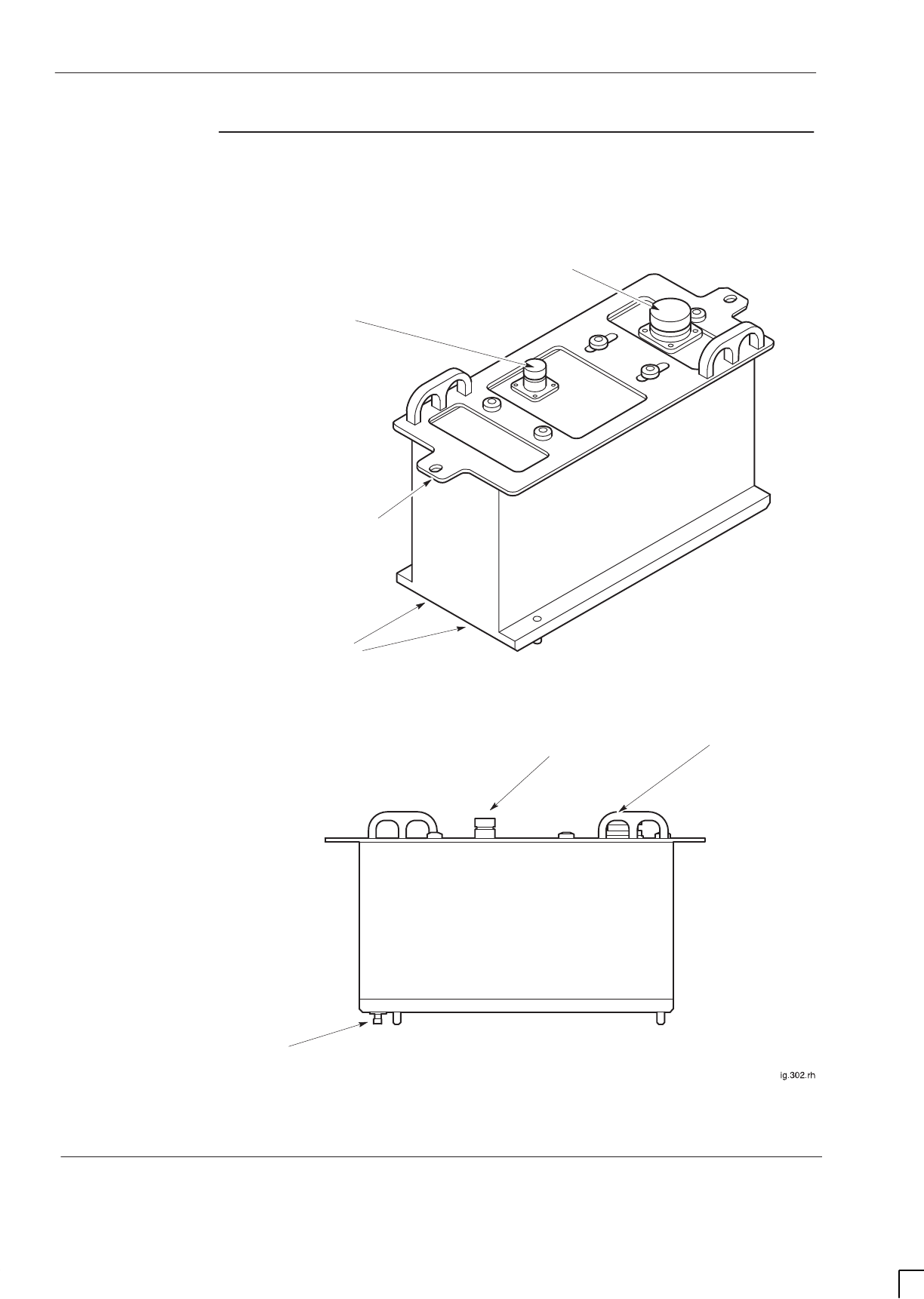
GSM-205-523
Replacing a Tx block, HCU or plate
31st Oct 01
Maint. 2–26
Maintenance Information: Horizon
macro
indoor
CONTROLLED INTRODUCTION
68P02902W09-B
Views of typical
Tx block
Figure 2-11 shows a typical Tx block module used in the Horizon
macro
indoor
cabinet.
SMA Tx CONNECTORS
FROM CTUs.
SIDE VIEW
ISOMETRIC VIEW
7/16 CONNECTOR TO
ANTENNA
N-TYPE CONNECTOR
TO SURF
HOLE FOR TOP
PANEL BASKET
ATTACHMENT
7/16 CONNECTOR TO
ANTENNA
N-TYPE CONNECTOR
TO SURF
SMA Tx CONNECTORS
FROM CTUs.
Figure 2-11 Views of typical Tx block

GSM-205-523 Replacing a Tx block, HCU or plate
31st Oct 01
Maintenance Information: Horizon
macro
indoor
68P02902W09-B
CONTROLLED INTRODUCTION
Maint. 2–27
Replacing a Tx
block
Removing a faulty Tx block
To remove a Tx block:
1. Locate the faulty Tx block, and note the RF cable connections to enable
correct reconnection to the replacement module.
WARNING Ensure that all CTUs associated with the faulty Tx block
are identified (for example inputs to an HCU or
feedthrough plate connected to a DDF).
2. Identify the CTUs that make Tx connections to the underside of the faulty
Tx block (plus any CTUs connected to the third Tx connector on top of a
DDF). See Table 2-3.
Table 2-3 Connectors for each type of Tx block module
Tx block SMA from transceiver TX 7/16 Rx/Tx
to antenna N-type Rx to
SURF
DCF 2 (beneath Tx block) 1 1
TDF
(including
dual band)
2 (beneath Tx block) 2 2
DDF 3 (2 beneath Tx block)
(1 on top of Tx block from HCU)
1 1
HCU 2 0 1 to next Tx block
3. Disable each CTU transmit RF power by using the shutdown_device
command at the OMC-R or from a PC connected to the MCUF. Refer to
Technical Description: BSS Command Reference (GSM–100–321)
for
information on usage and specific device codes.
4. When each CTU has been shutdown, check that the Tx status LED
(yellow) is extinguished.
5. Press and release each CTU circuit breaker button on the CBM to the out
(off) position. Ensure each RADIO STATUS LED is extinguished.
WARNING Ensure that RF power is OFF, before disconnecting RF
cables. Severe burns may result if RF power is ON when
RF cables are disconnected.
6. Disconnect all coaxial RF cables by carefully unscrewing and pulling them
out of the Tx block sockets. Note the positions for correct replacement.
7. Using a Torx driver, unscrew and retain the two M6 torx screws holding the
Tx block to the top of the cabinet.
WARNING Tx blocks can weigh as much as 5 kg. Handle with care.
8. Using the handles, lift the Tx block from the basket.

GSM-205-523
Replacing a Tx block, HCU or plate
31st Oct 01
Maint. 2–28
Maintenance Information: Horizon
macro
indoor
CONTROLLED INTRODUCTION
68P02902W09-B
Fitting a replacement Tx block
To install a replacement Tx block:
1. Transfer the protective caps on the RF connectors from the replacement
Tx block to the faulty Tx block.
2. Carefully insert the replacement Tx block into its basket location on the top
panel, adjusting alignment for retaining screws. Take care to avoid
trapping cables as the Tx block is seated.
3. Fit the two M6 torx screws to hold the Tx block to the top of the cabinet.
Tighten to correct torque (see Overview of replacement procedures).
4. Reconnect the coaxial RF cables to the positions noted in the removal
procedure. Tighten to correct torque (see Overview of replacement
procedures).
NOTE Ensure all unused SMA inputs to DCF, DDF and HCU
modules are fitted with 50 ohm load terminations.
5. Reset the appropriate CTU circuit breaker buttons on the CBM. Each
RADIO STATUS LED will flash green for about two minutes, and then
remain lit.
6. Enable the CTU transmit RF power by using the ins_device command
at the OMC-R or from a PC connected to the MCUF. The Tx STATUS LED
(yellow) will be lit if the CTU is transmitting.
7. Notify the OMC-R of base station availability and log the maintenance
activity.
Blanking plate,
feedthrough
plate or HCU
replacement
The procedure for plates is the same as for Tx blocks, but the plates are held by
six M4 screws in the base of the Tx block basket. The two M6 Tx block screw
locations are not used for plate attachment.
CAUTION Unused Tx block locations must be covered with a
blanking plate, with all screws fitted and tightened to the
correct torque (see Overview of replacement
procedures) to ensure correct airflow and EMC shielding.
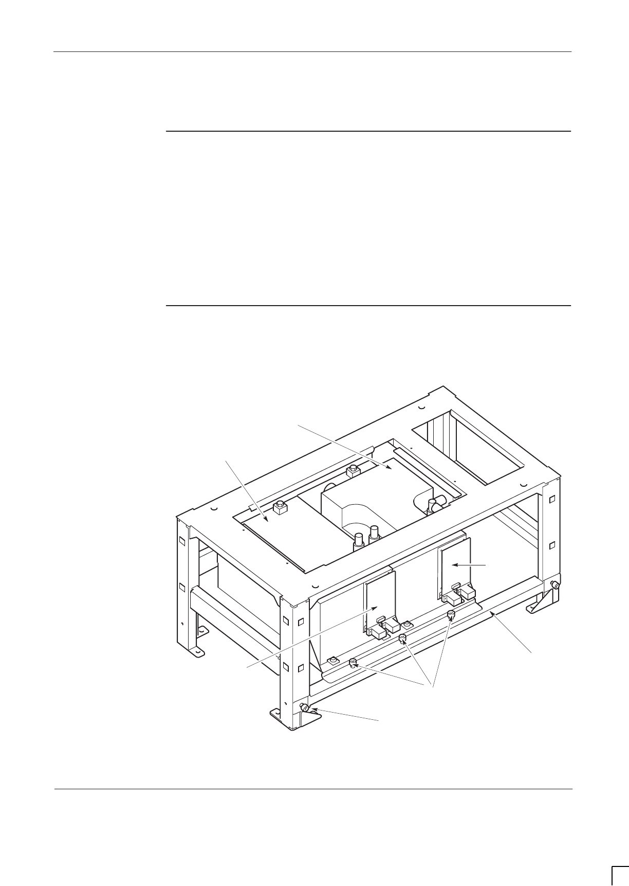
GSM-205-523 Replacing a CCB
31st Oct 01
Maintenance Information: Horizon
macro
indoor
68P02902W09-B
CONTROLLED INTRODUCTION
Maint. 2–29
Replacing a CCB
Overview of
CCB
replacement
CCBs, or their associated CCB control boards, can be individually replaced. It is
assumed that the OMC-R has identified which item requires replacement. CCB
block 0 is the right most block looking from the front, as shown in Figure 2-12,
and is the main CCB, with master CCB control board. CCB block 1 is the
extension CCB, with an optional redundant CCB control board.
The replacement of CCBs can only take place after the cabinet has been taken
out of service, in agreement with the OMC-R.
View of CCBs in
stacking
bracket
Figure 2-12 shows the CCBs located in stacking bracket (cabinet not shown).
ig.336.rh
CCB BASKET BAR
CCB1
CAPTIVE SCREW
ON BAR
CCB0
CCB CONTROL
BOARD
(MASTER)
CCB CONTROL
BOARD
(REDUNDANT) CAPTIVE SCREWS
ON CCB BASKET
Figure 2-12 CCBs in installed position with CCB basket bar attached

GSM-205-523
Replacing a CCB
31st Oct 01
Maint. 2–30
Maintenance Information: Horizon
macro
indoor
CONTROLLED INTRODUCTION
68P02902W09-B
Removing
CCBs and CCB
control boards
WARNING Before disconnecting RF cables, ensure that the RF
power is OFF by turning cabinet PSMs off. If RF power is
ON when cables are disconnected, severe burns may
result.
The removal off CCBs is accomplished in two stages:
SRemoving the CCB basket from the stacking bracket.
SSeparating CCBs from CCB basket.
Removing the CCB basket from the stacking bracket
To remove the CCB basket:
1. Close cabinet down by turning off PSMs.
2. Remove the stacking bracket front cover by applying gentle pressure to
the outer edges, while easing the cover up and pulling it away from the
bracket.
3. Disconnect power cable from each CCB and from single connector
(marked CCB) on Interface panel.
CAUTION Do not detach CCB basket bar unless basket is to be
immediately removed.
4. Loosen the three captive screws attaching CCB basket bar to basket and
the two captive screws securing CCB basket bar to the sides of the
stacking bracket. Remove the bar
5. Disconnect the six N-type to N-type RF cables from the CCB inputs, and
leave draped over the front of the cabinet. Note the locations for correct
replacement.
6. Slide basket part way out of the stacking bracket, and disconnect
antennas to CCBs.
7. Remove the CCB basket, complete with CCBs, from stacking bracket.
Separating CCBs from the CCB basket
To separate CCBs from CCB basket:
1. Place the CCB basket, complete with CCBs, onto a flat surface.
2. Disconnect and remove the phasing lead between CCB control boards.
3. Remove the four M4 screws securing each control board cover, and
remove the CCB control boards.
4. Remove the six screws securing each CCB to the basket, (four M6 screws
on the front and two M8 screws at the back).
5. Remove the CCBs from the basket
The CCBs have now been removed, ready for replacement CCBs.

GSM-205-523 Replacing a CCB
31st Oct 01
Maintenance Information: Horizon
macro
indoor
68P02902W09-B
CONTROLLED INTRODUCTION
Maint. 2–31
Fitting
replacement
CCBs and CCB
control boards
Follow these procedures to fit replacement CCBs.
Fitting CCBs into the basket
1. Place CCB basket onto flat surface.
2. Place the CCBs into the basket and secure with four M6 screws on the
front and two M8 screws at the back. Tighten to correct torque (see
Overview of replacement procedures).
3. Insert each CCB control board, then securing cover with four M4 screws.
Tighten to correct torque (see Overview of replacement procedures).
4. Connect phasing lead between CCB control boards.
Fitting the basket to the stacking bracket
1. Ensure N-type cables are connected to the feedthrough plates and draped
over the front of the cabinet.
2. Slide the basket part way into the stacking bracket, and connect antennas
to the CCBs.
3. Slide the CCB basket fully home.
4. Connect the six N-type to N-type RF cables from the feedthrough plates to
the CCB inputs. Connect to the positions noted in the removal procedure.
5. Attach the CCB basket bar to the sides of the stacking bracket using the
two captive screws. The bar is then directly underneath the basket captive
screws.
6. Attach the CCB basket bar to the basket with the three captive screws on
the basket.
7. Connect the power cable to each CCB from the single connector (marked
CCB) on the Interface panel.
8. Refit the front cover onto the stacking bracket, pushing it in so that it can
drop into position on the side lugs.
The CCBs are now replaced and ready for power up of the cabinet.
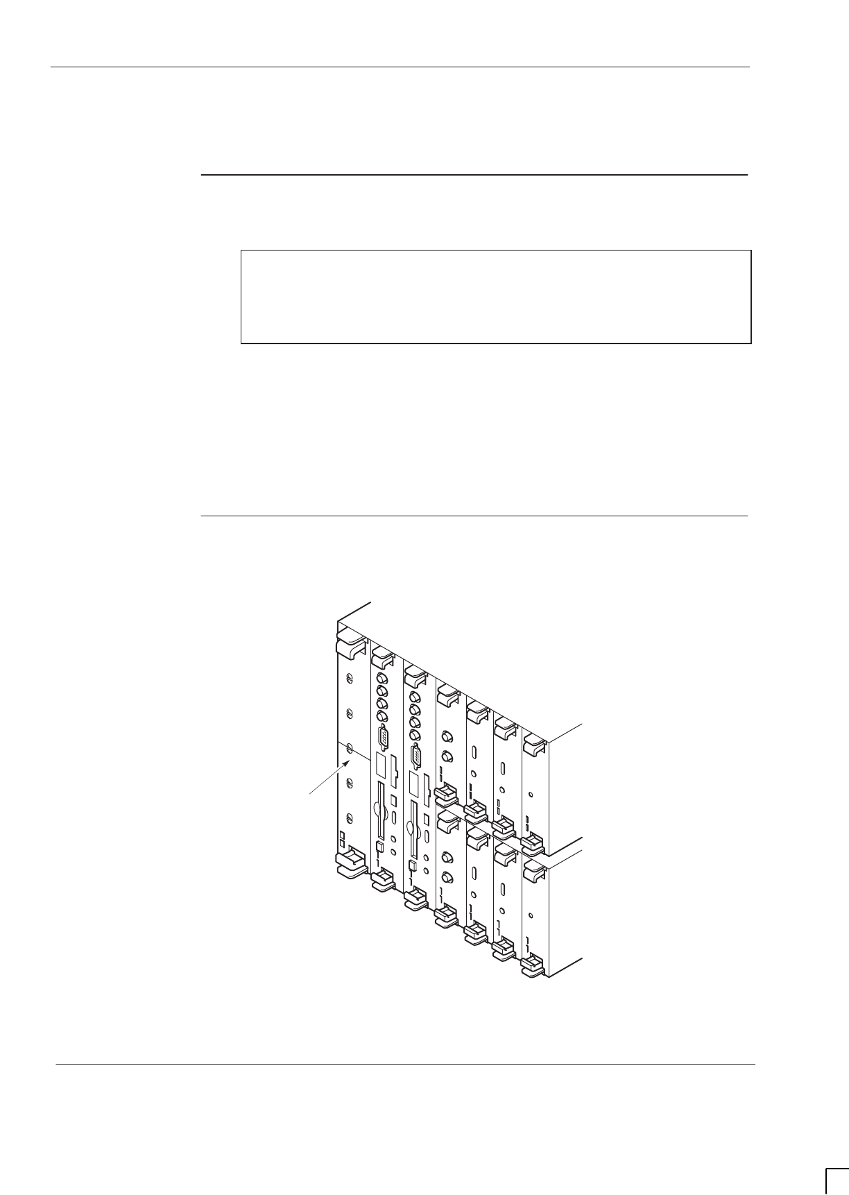
GSM-205-523
Digital module replacement (MCUF, NIU, FMUX, BPSM, Alarm)
31st Oct 01
Maint. 2–32
Maintenance Information: Horizon
macro
indoor
CONTROLLED INTRODUCTION
68P02902W09-B
Digital module replacement (MCUF, NIU, FMUX, BPSM, Alarm)
Introduction to
digital module
replacement
CAUTION MCUF removal during flash memory programming may
result in bootcode corruption. This is only repairable by
returning the MCUF to Motorola. For this reason, the
MCUF should not be removed while the code load is
taking place, indicated by a flashing LED.
A faulty master MCUF, FMUX or BPSM will cause a redundant module (if fitted)
to take over until the faulty module is replaced. Faulty MCUF, FMUX and BPSM
modules can be hot swapped without harm to the module or effect on normal
operation, provided the equivalent redundant module has taken over.
Removal of a faulty digital module that has not had its function taken over by a
redundant module, and is still partially functional, will affect service. Inform the
OMC-R before replacing out such modules.
Diagram of
digital modules
Figure 2-13 shows the location of modules within the digital module shelf.
ig.322.rh
ALARM
MODULE
NIU B0
NIU B1
BPSM
BPSM
FMUX
FMUX
MCUF A
MCUF B
NIU A0
NIU A1
REDUNDANT (B)
MASTER (A)
DIGITAL
MODULE SHELF
Figure 2-13 Digital and BPSM module locations, including optional redundancy

GSM-205-523 Digital module replacement (MCUF, NIU, FMUX, BPSM, Alarm)
31st Oct 01
Maintenance Information: Horizon
macro
indoor
68P02902W09-B
CONTROLLED INTRODUCTION
Maint. 2–33
Replacing
digital modules
Removing a faulty digital module
To remove a digital module:
WARNING There is a possibility of laser radiation when fibre optic
cables are disconnected. Do not look directly into cables
with or without the use of any optical aids. Radiation can
come from either the data in/out connectors or
unterminated fibre optic cables connected to data in/out
connectors.
CAUTION An earthing wrist strap must be worn when handling digital
modules. An ESP earthing connection point is provided
above the leftmost PSM.
1. If the faulty digital module is still partially functional, due to no redundancy
option, inform the OMC-R before proceeding.
2. Locate the faulty module, as shown in Figure 2-13.
3. Note location of any fibre optic cable connections to the module, (MCUF or
FMUX modules only), to enable correct reconnection to the replacement
module.
4. Disconnect each fibre optic cable by gently pushing the knurled connector
in and rotating it through a quarter-turn anticlockwise to disengage, then
withdraw the cable carefully.
NOTE It is advisable to protect the tips of the fibre optic cables
with a protective cover and secure the cables to one side.
5. Unseat the module by gripping the upper and lower pair of ejectors
between the thumb and first finger of each hand, then gently squeeze and
pull on the ejectors until the module unclips at the top and bottom of the
front panel and unplugs from the rear connector.
6. Carefully slide the module from its location and place it in an anti-static
storage container.

GSM-205-523
Digital module replacement (MCUF, NIU, FMUX, BPSM, Alarm)
31st Oct 01
Maint. 2–34
Maintenance Information: Horizon
macro
indoor
CONTROLLED INTRODUCTION
68P02902W09-B
Fitting replacement digital module
To install a replacement digital module:
1. Remove the replacement module from the antistatic storage container. In
the case of the NIU, ensure it is of the correct type (E1 or T1).
2. Slide the module into the guide rails and push firmly into place. The
ejectors will audibly click into place as confirmation of correct insertion.
3. Connect any fibre optic cables by inserting the connector and rotating a
quarter-turn clockwise to engage.
NOTE Ensure fibre optic cables are correctly connected to the
locations noted during module removal.
4. Ensure appropriate LEDs indicate correct operation.
CAUTION When the two LEDs of the MCUF, are flashing, the boot
code is downloading into non-volatile memory for software
upgrade. Power should not be removed, nor the cabinet
reset, until downloading has been completed, as this will
corrupt the non-volatile memory. If the boot code is
corrupted, contact Motorola Customer Network Resolution
Centre requesting the boot code restoration procedure
and the appropriate boot code file.
NOTE Following an NIU switch on or reboot, both red and green
LEDs are initially lit. After approximately 20 seconds, the
red LED will extinguish, indicating normal condition. This
waiting period may be extended to 50 seconds after
rebooting due to a code download.
5. When fitting a redundant MCUF refer to Redundant MCUF firmware
compatibility for details of further checks required.
6. Notify the OMC-R of base station availability and log the maintenance
activity.

GSM-205-523 Redundant MCUF firmware compatibility
31st Oct 01
Maintenance Information: Horizon
macro
indoor
68P02902W09-B
CONTROLLED INTRODUCTION
Maint. 2–35
Redundant MCUF firmware compatibility
Overview of
MCUF firmware
compatibility
In many installations a redundant MCUF is fitted and configured to assume
control in the event of a failure of the master MCUF. Under normal
circumstances, the redundant MCUF accepts code downloads from the master
MCUF and so remains updated and available for use.
If the redundant MCUF is replaced with a module containing firmware which is
incompatible with the master MCUF firmware, then the communicating link
between MCUFs will not be established. The redundant MCUF will therefore not
be updated and will not be available to take over when required.
Checking MCUF
firmware
compatibility
To check firmware compatibility between MCUFs, check the state of the base
transceiver processor (BTP) within each MCUF as follows:
1. Connect a PC to the TTY connection on the master MCUF.
2. At the CUST MMI prompt, enter:
state <site #> btp * *
Where <site #> is the site number.
The status of both BTPs will be displayed as follows:
BTP 0 0 0 B–U NO REASON
BTP 1 0 0 E–U NO REASON
or,
BTP 0 0 0 B–U NO REASON
BTP 1 0 0 D–U No Redundant Link
If No Redundant Link is indicated then the master MCUF is not in communication
with the redundant MCUF and firmware incompatibility may be assumed. Refer
to Updating redundant MCUF firmware.
Updating
redundant
MCUF firmware
The following procedure to update firmware in the redundant MCUF requires a
PCMCIA card containing current network configuration data. The procedure
assumes that the PCMCIA card is already in the master MCUF.
NOTE No call processing can take place during the MCUF
firmware update process. The entire process should take
approximately one hour.

GSM-205-523
Redundant MCUF firmware compatibility
31st Oct 01
Maint. 2–36
Maintenance Information: Horizon
macro
indoor
CONTROLLED INTRODUCTION
68P02902W09-B
Site preparation
To prepare for the firmware update the site must first be taken out-of-service as
follows:
1. Connect a PC to the TTY connection on the master MCUF.
2. At the CUST MMI prompt, disable all CTUs in turn by typing:
shutdown_device <site #> dri * * * <seconds>
Where <site #> is the site number, * * * is the DRI identifier and
<seconds> is the time delay before shutdown occurs.
3. Confirm this action by observing each CTU Tx status LED, which should
extinguish shortly after issuing the shutdown command.
4. Disconnect the 2.048 Mbit/s link
Redundant MCUF firmware update procedure
The following procedure describes how to update redundant MCUF firmware by
placing the redundant MCUF into the master position and downloading code
from a PCMCIA card.
1. Remove the uploaded PCMCIA card from the master MCUF, and ensure
that write protect is switched to OFF.
2. Remove both MCUFs. Insert the PCMCIA card into the original redundant
MCUF then insert this MCUF into the master position.
3. Connect a PC to the TTY connection on the MCUF front panel.
4. At the MMI-ROM prompt, type:
burn
This will flash object 8, the MCUF boot object, from the PCMCIA card onto
the MCUF card. The flash download takes approximately 30 seconds,
then the MCUF will reset.
5. At the MMI ROM prompt, type:
set_site <site #>
Where <site #> is the site number.
The MCUF now carries out a system initialization using data from the
PCMCIA card. After a short wait the screen displays:
Initialization complete. All commands accepted.
The MCUF firmware update is complete and both MCUFs now hold
identical firmware. The MCUF originally removed from the master position
may now be used in the redundant position.
6. Insert the original master MCUF into the redundant position.
The redundant MCUF now requires a 15 minute sync warm up period,
followed by a further delay of four minutes while the two MCUFs achieve
phase lock. Once phase lock is achieved the master MCUF immediately
begins codeloading to the redundant MCUF. Codeloading takes a further
15 minutes.
The process is complete when the following message is displayed on
screen:
Redundant MSW is INS
<*><*><*> NEW STANDBY Switch CONFIGURED <*><*><*>

GSM-205-523 Redundant MCUF firmware compatibility
31st Oct 01
Maintenance Information: Horizon
macro
indoor
68P02902W09-B
CONTROLLED INTRODUCTION
Maint. 2–37
7. To confirm correct MCUF status, at the CUST MMI prompt, enter:
state <site #> btp * *
Where <site #> is the site number.
The status of both BTPs will be displayed as follows:
BTP 0 0 0 B–U NO REASON
BTP 1 0 0 E–U NO REASON
Where B–U is busy unlocked (master) and E-U is enabled unlocked
(redundant).
8. Reconnect the 2.048 Mbit/s link.
NOTE There is no need to unlock the CTUs as these are
automatically unlocked during the initialization procedure.
NOTE If a PCMCIA card is not available then the firmware in the
redundant MCUF may be updated by removing the master
MCUF and placing the redundant MCUF in the master
position. Code download from the BSC will ensure the
newly installed MCUF is fully updated. This procedure
however is likely to take up to 30 minutes longer than the
procedure involving a PCMCIA card, resulting in a longer
out of service time for the BTS.

GSM-205-523
Redundant MCUF firmware compatibility
31st Oct 01
Maint. 2–38
Maintenance Information: Horizon
macro
indoor
CONTROLLED INTRODUCTION
68P02902W09-B
Testing MCUF
redundancy
The following procedure tests MCUF redundancy by forcing the master and
redundant MCUFs to swap roles. The commands refer to the base transceiver
processors (BTPs) within each MCUF.
1. Connect a PC to the TTY connection on the master MCUF.
2. At the CUST MMI prompt, type:
state <site #> btp * *
Where <site #> is the site number.
The status of both BTPs will be displayed as follows:
BTP 0 0 0 B–U NO REASON
BTP 1 0 0 E–U NO REASON
Where B–U is busy unlocked (master) and E-U is enabled unlocked
(redundant).
3. At the CUST MMI prompt type:
swap_devices <site #> btp 0 0 0 btp 1 0 0
Where <site #> is the site number, btp 0 0 0 is the master MCUF and btp
1 0 0 is the redundant MCUF.
This command will swap MCUF roles by forcing:
Sthe redundant MCUF into a busy state , and making it master.
Sthe master MCUF into an enabled state, and making it redundant.
4. At the CUST MMI prompt, confirm the swap by typing:
state <site #> btp * *
Where <site #> is the site number.
The status of both BTPs will now show changed roles:
BTP 0 0 0 E–U NO REASON
BTP 1 0 0 B–U NO REASON
5. Make test calls on the site to verify the new master MCUF.
6. At the CUST MMI prompt type, swap the MCUFs back to their original
states by typing:
swap_devices <site #> btp 1 0 0 btp 0 0 0
Where <site #> is the site number, btp 1 0 0 is the master MCUF and btp
0 0 0 is the redundant MCUF.
7. At the CUST MMI prompt, confirm the swap by typing:
state <site #> btp * *
Where <site #> is the site number.
Both BTPs have now reverted to their original roles:
BTP 0 0 0 B–U NO REASON
BTP 1 0 0 E–U NO REASON
8. Make test calls on the site to verify the new master MCUF.

CHAPTER 1
INDOOR PARTS LIST


31st Oct 01
Parts Information: Horizon
macro
indoor
68P02902W10-B
CONTROLLED INTRODUCTION
i
Category 623
Parts Information (Parts)

GSM-205-623
31st Oct 01
ii
Parts Information: Horizon
macro
indoor
CONTROLLED INTRODUCTION
68P02902W10-B

GSM-205-623
31st Oct 01
Parts Information: Horizon
macro
indoor
68P02902W10-B
CONTROLLED INTRODUCTION
iii
Category 623
Parts Information (Parts) i. . . . . . . . . . . . . . . . . . . . . . . . . . . . . . . . . . . . . . . . . . .
Chapter 1
Parts list i. . . . . . . . . . . . . . . . . . . . . . . . . . . . . . . . . . . . . . . . . . . . . . . . . . . . . .
Horizonmacro indoor parts list Parts 1–1. . . . . . . . . . . . . . . . . . . . . . . . . . . . . . . . . . . . . . . . .
Introduction to Horizonmacro indoor parts list Parts 1–1. . . . . . . . . . . . . . . . . . . . . . .
FRU items Parts 1–1. . . . . . . . . . . . . . . . . . . . . . . . . . . . . . . . . . . . . . . . . . . . . . . . . . . . .
Ordering method Parts 1–1. . . . . . . . . . . . . . . . . . . . . . . . . . . . . . . . . . . . . . . . . . . . . . . .
Diagram of cabinet modules Parts 1–2. . . . . . . . . . . . . . . . . . . . . . . . . . . . . . . . . . . . . .
Spares tables Parts 1–3. . . . . . . . . . . . . . . . . . . . . . . . . . . . . . . . . . . . . . . . . . . . . . . . . .
View of CCBs in stacking bracket Parts 1–5. . . . . . . . . . . . . . . . . . . . . . . . . . . . . . . . .
CCB spares table Parts 1–5. . . . . . . . . . . . . . . . . . . . . . . . . . . . . . . . . . . . . . . . . . . . . . .
Digital module and BPSM locations Parts 1–6. . . . . . . . . . . . . . . . . . . . . . . . . . . . . . .
Digital module and BPSM table Parts 1–6. . . . . . . . . . . . . . . . . . . . . . . . . . . . . . . . . . .
Diagram of the door Parts 1–7. . . . . . . . . . . . . . . . . . . . . . . . . . . . . . . . . . . . . . . . . . . . .
Door table Parts 1–7. . . . . . . . . . . . . . . . . . . . . . . . . . . . . . . . . . . . . . . . . . . . . . . . . . . . .
Diagram of hood Parts 1–8. . . . . . . . . . . . . . . . . . . . . . . . . . . . . . . . . . . . . . . . . . . . . . . .
Indoor hood table Parts 1–8. . . . . . . . . . . . . . . . . . . . . . . . . . . . . . . . . . . . . . . . . . . . . . .
Glossary of unique terms for this equipment Parts 1–9. . . . . . . . . . . . . . . . . . . . . . . . . . . . .
Overview Parts 1–9. . . . . . . . . . . . . . . . . . . . . . . . . . . . . . . . . . . . . . . . . . . . . . . . . . . . . .
Glossary terms Parts 1–9. . . . . . . . . . . . . . . . . . . . . . . . . . . . . . . . . . . . . . . . . . . . . . . . .

GSM-205-623
31st Oct 01
iv
Parts Information: Horizon
macro
indoor
CONTROLLED INTRODUCTION
68P02902W10-B

31st Oct 01
Parts Information: Horizon
macro
indoor
68P02902W10-B
CONTROLLED INTRODUCTION
i
Chapter 1
Parts list

GSM-205-623
31st Oct 01
ii
Parts Information: Horizon
macro
indoor
CONTROLLED INTRODUCTION
68P02902W10-B

GSM-205-623
31st Oct 01
Parts Information: Horizon
macro
indoor
68P02902W10-B
CONTROLLED INTRODUCTION
iii
Chapter 1
Parts list i. . . . . . . . . . . . . . . . . . . . . . . . . . . . . . . . . . . . . . . . . . . . . . . . . . . . . .
Horizonmacro indoor parts list Parts 1–1. . . . . . . . . . . . . . . . . . . . . . . . . . . . . . . . . . . . . . . . .
Introduction to Horizonmacro indoor parts list Parts 1–1. . . . . . . . . . . . . . . . . . . . . . .
FRU items Parts 1–1. . . . . . . . . . . . . . . . . . . . . . . . . . . . . . . . . . . . . . . . . . . . . . . . . . . . .
Ordering method Parts 1–1. . . . . . . . . . . . . . . . . . . . . . . . . . . . . . . . . . . . . . . . . . . . . . . .
Diagram of cabinet modules Parts 1–2. . . . . . . . . . . . . . . . . . . . . . . . . . . . . . . . . . . . . .
Spares tables Parts 1–3. . . . . . . . . . . . . . . . . . . . . . . . . . . . . . . . . . . . . . . . . . . . . . . . . .
View of CCBs in stacking bracket Parts 1–5. . . . . . . . . . . . . . . . . . . . . . . . . . . . . . . . .
CCB spares table Parts 1–5. . . . . . . . . . . . . . . . . . . . . . . . . . . . . . . . . . . . . . . . . . . . . . .
Digital module and BPSM locations Parts 1–6. . . . . . . . . . . . . . . . . . . . . . . . . . . . . . .
Digital module and BPSM table Parts 1–6. . . . . . . . . . . . . . . . . . . . . . . . . . . . . . . . . . .
Diagram of the door Parts 1–7. . . . . . . . . . . . . . . . . . . . . . . . . . . . . . . . . . . . . . . . . . . . .
Door table Parts 1–7. . . . . . . . . . . . . . . . . . . . . . . . . . . . . . . . . . . . . . . . . . . . . . . . . . . . .
Diagram of hood Parts 1–8. . . . . . . . . . . . . . . . . . . . . . . . . . . . . . . . . . . . . . . . . . . . . . . .
Indoor hood table Parts 1–8. . . . . . . . . . . . . . . . . . . . . . . . . . . . . . . . . . . . . . . . . . . . . . .
Glossary of unique terms for this equipment Parts 1–9. . . . . . . . . . . . . . . . . . . . . . . . . . . . .
Overview Parts 1–9. . . . . . . . . . . . . . . . . . . . . . . . . . . . . . . . . . . . . . . . . . . . . . . . . . . . . .
Glossary terms Parts 1–9. . . . . . . . . . . . . . . . . . . . . . . . . . . . . . . . . . . . . . . . . . . . . . . . .

GSM-205-623
31st Oct 01
iv
Parts Information: Horizon
macro
indoor
CONTROLLED INTRODUCTION
68P02902W10-B

GSM-205-623 Horizonmacro indoor parts list
31st Oct 01
Parts Information: Horizon
macro
indoor
68P02902W10-B
CONTROLLED INTRODUCTION
Parts 1–1
Horizon
macro
indoor parts list
Introduction to
Horizon
macro
indoor parts list
In the parts lists contained in this chapter, each item consists of a location
number (related to the associated diagram), description, and an order number.
The order number uniquely identifies the required component. Some
components are used in different equipment in addition to Horizon
macro
indoor.
Many items are the same for Horizon
macro
outdoor. Several items are the same
for M-Cell
6
.
FRU items
The majority of items on the parts list are field replaceable units (FRUs). It is not
intended to supply sub-units of these spares.
Ordering
method
Contact the local Motorola office for ordering information, including cost and
delivery.
If an item in the parts list is marked TBA, this means that the part number for the
item was not available at the time of publication of this manual.
NOTE Motorola reserves the right to change the design of the
product without notice. The information provided in this
chapter is intended as a guide. If the customer requires
the latest information, then consult the Motorola local
office who will be able to check on the web and confirm
the current situation.
Some items, for example CCBs and PSMs, are produced
by different manufacturers, and so a replacement may
appear slightly different to the item it is replacing. All items
bearing the same order number, regardless of
manufacturer, are fully compatible.
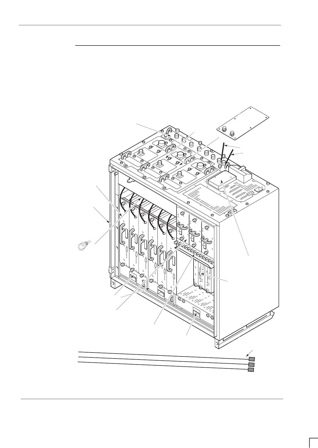
GSM-205-623
Horizonmacro indoor parts list
31st Oct 01
Parts 1–2
Parts Information: Horizon
macro
indoor
CONTROLLED INTRODUCTION
68P02902W10-B
Diagram of
cabinet
modules
Figure 1-1 to Figure 1-5 shows the cabinet modules, including major FRUs,
without door or hood/stacking bracket for clarity.
DIGITAL MODULE
SHELF
(see Figure 1-3)
SIX CTUs
ONE SURF
(Rx)
TWO 2-FAN
UNITS
ONE 4-FAN
UNIT
1
2
3
4
FEEDTHROUGH
PLATE
5
INDOOR SPLIT
SECTOR CABLE
PAIR
6
EXTENSION CABINET
OPTICAL FIBRE
9
7
8
10
11
12
3 x PSMs OR 2 x PSMs
+ HOLD-UP BATTERY
MODULE
T43/BIB
THREE Tx BLOCKS
(DCFs SHOWN AS
EXAMPLE)
CIRCUIT BREAKER
MODULE (CBM)
13
50 OHM LOAD
(FITTED TO
UNUSED PORT)
14
Figure 1-1 Diagram of indoor cabinet showing major FRUs

GSM-205-623 Horizonmacro indoor parts list
31st Oct 01
Parts Information: Horizon
macro
indoor
68P02902W10-B
CONTROLLED INTRODUCTION
Parts 1–3
Spares tables
Table 1-1 to Table 1-5 list the Horizon
macro
indoor spares, available as at
October 2001. Location numbers in each table refer to the associated preceding
diagram. Contact the Motorola local office for an up to date list.
Table 1-1 List of Horizon
macro
indoor spares
Location Description Order No
1Indoor cabinet SW1053
21900 CTU TBA
31900 SURF TBA
41900 DCF TBA
41900 DDF TBA
41900 HCU TBA
41900 TDF TBA
21800 CTU SWRG5197
31800 SURF (single band) SWRG2880
31800 SURF (dual band) TBA
41800 DCF SVLG1224
41800 DDF SVLG1225
41800 HCU SVLG1227
41800 TDF SVLG1226
2900 CTU SWRF5193
3900 SURF (single band) TBA
3900 SURF (dual band) SWRF2879
4900 DCF SVLF1224
4900 DDF SVLF1225
4900 HCU SVLF1227
4900 TDF SVLF1226
2850 CTU TBA
3850 SURF TBA
4850 DCF TBA
4850 DDF TBA
4850 HCU TBA
4850 TDF TBA
4Dual band TDF SVLX1198
5Feedthrough plate assembly SVLN1243
6Indoor split sector cable pair SVKN1233

GSM-205-623
Horizonmacro indoor parts list
31st Oct 01
Parts 1–4
Parts Information: Horizon
macro
indoor
CONTROLLED INTRODUCTION
68P02902W10-B
Location Order NoDescription
7 BIM/BIB SWLN4024
7 CIM/T43 SWLN4025
8Digital module shelf (see Table 1-3)
92nd (Extension) cabinet fibre SVKN1244
93rd (Extension) cabinet fibre SVKN1245
94th (Extension) cabinet fibre SVKN1246
10 4-fan unit SWHN5790
11 CBM SWHN5519
12 Hold-up battery module SVPN1161
12 Indoor 27 V PSM SVPN1220
12 Indoor –48 V PSM SVPN1221
12 Indoor 240 V PSM SVPN1222
13 2-fan unit SWHN5289
14 SMA 50 ohm load SVLN1230
Indoor plinth SVLN1247
*Indoor blanks set SVLN1219
PCMCIA SWLN5239
Air filter kit (pack of 10) SVFF1209
CTU Tx cable SVKN1304
Duplexer cable SVKN1305
GPS cable SWKN8115
NOTE *These are sets of blank plates which fit PSMs, Tx blocks
and CTUs.
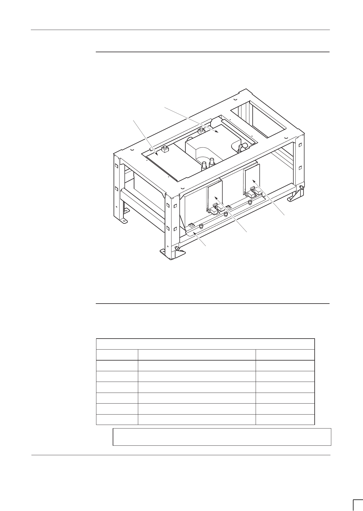
GSM-205-623 Horizonmacro indoor parts list
31st Oct 01
Parts Information: Horizon
macro
indoor
68P02902W10-B
CONTROLLED INTRODUCTION
Parts 1–5
View of CCBs in
stacking bracket
Figure 1-2 shows the CCBs located in the stacking bracket.
ig.336.rh
CCB1
CCB0
CCB CONTROL
BOARD (MASTER)
CCB CONTROL
BOARD
(REDUNDANT)
1
1
2
2
3
CCB
INSTALLATION
KIT (BASKET)
Figure 1-2 CCBs in installed position with CCB basket bar attached
CCB spares
table
Table 1-2 outlines the spares for the CCBs and stacking bracket.
Table 1-2 CCB and stacking bracket spares
Location Description Order No
11800 CCB (Master) SVLG1241
11800 CCB (Extender) SVLG1242
1900 CCB (Master) SVLF1241
1900 CCB (Extender) SVLF1242
2CCB control board SWLN4507
3CCB installation kit SWHN5927
NOTE CCBs are not currently available for the GSM850 and
PCS1900 BTS variants.
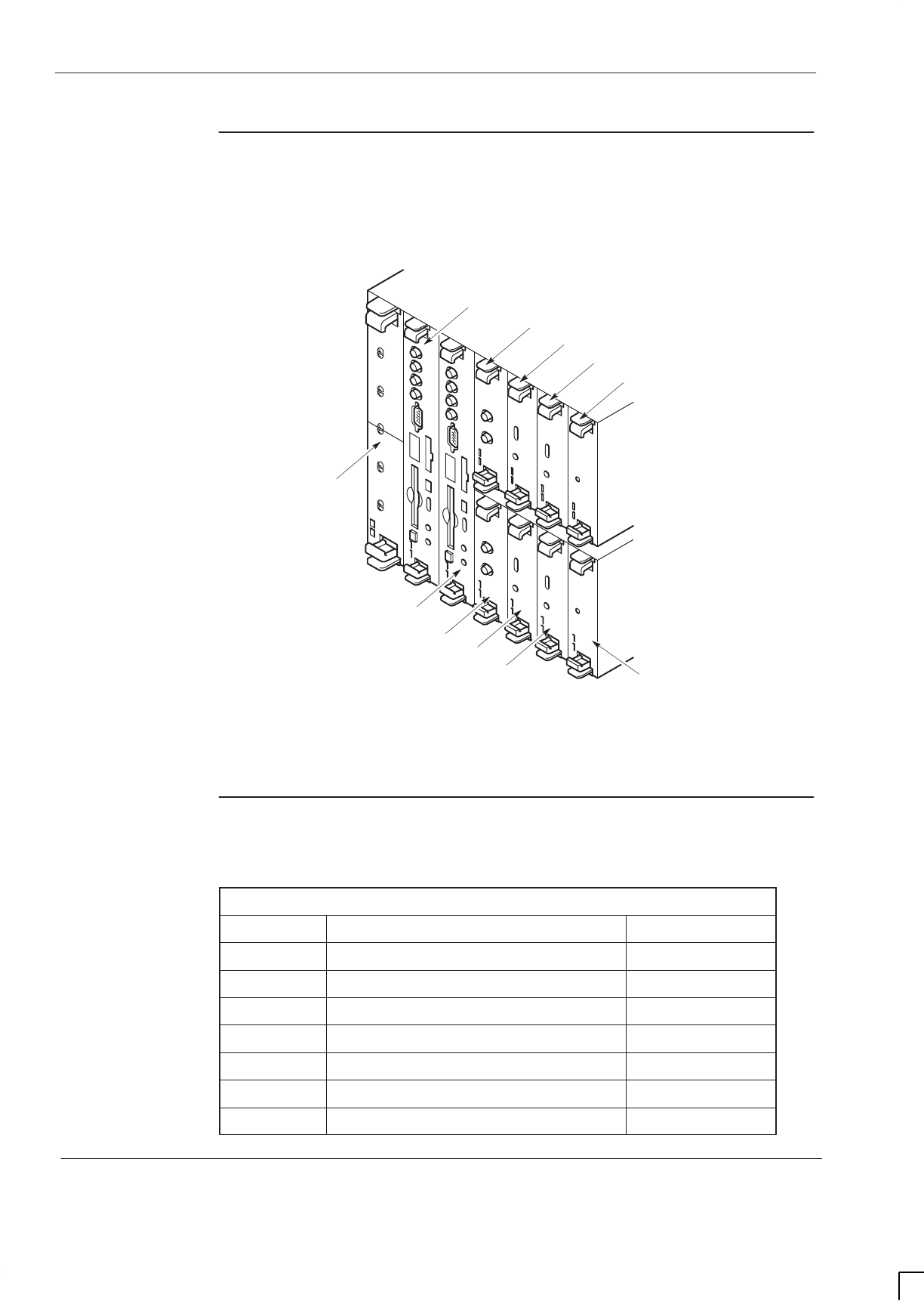
GSM-205-623
Horizonmacro indoor parts list
31st Oct 01
Parts 1–6
Parts Information: Horizon
macro
indoor
CONTROLLED INTRODUCTION
68P02902W10-B
Digital module
and BPSM
locations
Figure 1-3 shows the individual digital module and microBCU power supply
module (BPSM) locations.
ig.322.rh
ALARM
MODULE
NIU B0
NIU B1
BPSM
BPSM
FMUX
FMUX
MCUF A
MCUF B
NIU A0
NIU A1
REDUNDANT (B)
MASTER (A)
DIGITAL
MODULE SHELF
1
2
3
2
4
45
3
4
4
5
Figure 1-3 Digital module and BPSM locations
Digital module
and BPSM table
Table 1-3 outlines the spares for the digital modules and BPSM.
Table 1-3 Digital module and BPSM spares
Location Description Order No
1Alarm module SWLN5228
1Alarm module with GPS functionality SWLN8510
2 MCUF SWLN5227
3 FMUX SWLN4406
4 NIU-E1 SWLN4403
4 NIU-T1 SWLN4404
5 BPSM SWPN2567
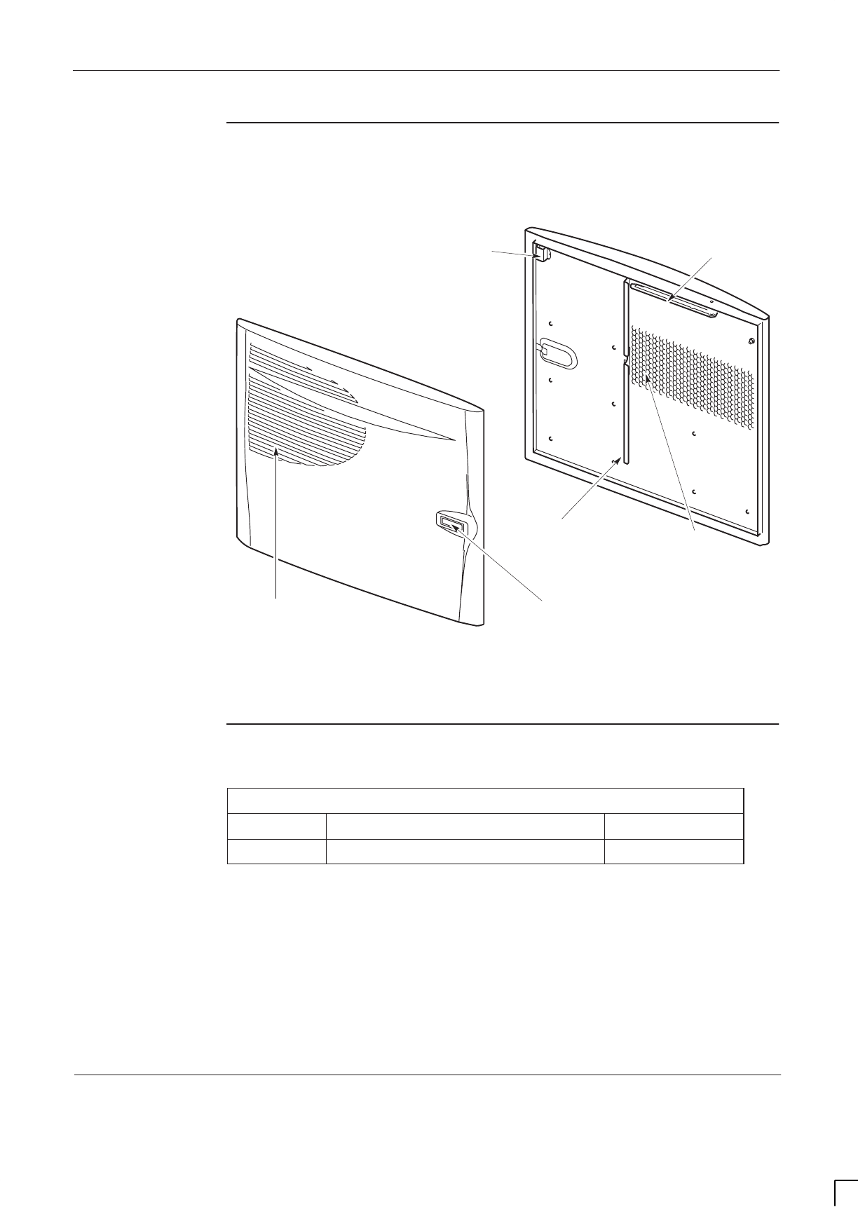
GSM-205-623 Horizonmacro indoor parts list
31st Oct 01
Parts Information: Horizon
macro
indoor
68P02902W10-B
CONTROLLED INTRODUCTION
Parts 1–7
Diagram of the
door
Figure 1-4 shows the internal and external view of the door.
ig.266.rh
VENTILATION
GRID
EXTERNAL VIEW
TRIGGER
LATCH
INTERNAL VIEW
VERTICAL AIR
BAFFLE
DOOR ALARM
BRACKET
HONEYCOMB
VENTILATION
DOOR STOP
BRACKET
Figure 1-4 Internal and external view of the door
Door table
Table 1-4 outlines the door spare.
Table 1-4 Door spare
Location Description Order No
1Indoor door SWHN5556
GSM-205-623
Horizonmacro indoor parts list
31st Oct 01
Parts 1–8
Parts Information: Horizon
macro
indoor
CONTROLLED INTRODUCTION
68P02902W10-B
Diagram of
hood
Figure 1-5 shows a top view of the optional hood.
1
Figure 1-5 View of the hood as seen from the front of the cabinet
Indoor hood
table
Table 1-5 outlines the indoor hood spare.
Table 1-5 Indoor hood spare
Location Description Order No
1Indoor hood SVLN1231

GSM-205-623 Glossary of unique terms for this equipment
31st Oct 01
Parts Information: Horizon
macro
indoor
68P02902W10-B
CONTROLLED INTRODUCTION
Parts 1–9
Glossary of unique terms for this equipment
Overview
These glossary items have been selected as unique to this Horizon
macro
product, or common only to M-Cell
6
. These and other GSM terms can be found
in
System Information: General: (GSM-100-101)
.
Glossary terms
BPSM
Micro BCU Power Supply Module
CBM
Circuit Breaker Module
CCB
Cavity Combining Block
CTU
Compact Transceiver Unit
DCF
Duplexed Combining bandpass Filter
DDF
Dual-stage Duplexed combining Filter
FMUX
Fibre optic Multiplexer
HCU
Hybrid Combining Unit
HPD
High Powered Duplexer
MCUF
Main Control Unit with dual FMUX
NIU
Network Interface Unit
SURF
Sectorized Universal Receiver Front-end
TDF
Twin Duplexed Filter

GSM-205-623
Glossary of unique terms for this equipment
31st Oct 01
Parts 1–10
Parts Information: Horizon
macro
indoor
CONTROLLED INTRODUCTION
68P02902W10-B

31st Oct 01
Service Manual: Horizon
macro
indoor
68P02902W06-B
CONTROLLED INTRODUCTION
I–1
Index

GSM-205-020
31st Oct 01
I–2
Service Manual: Horizon
macro
indoor
CONTROLLED INTRODUCTION
68P02902W06-B

GSM-205-020
31st Oct 01
Service Manual: Horizon
macro
indoor
68P02902W06-B
CONTROLLED INTRODUCTION
I–3
Symbols
+ 27 V dc, connection procedure, Inst. 2–56
– 48/60 V dc, connection procedure, Inst. 2–57
Numbers
2.048 Mbit/s lines
testing, Inst. 2–3
transient protection, Inst. 2–21
7/16 connector, when used, Inst. 2–23
A
AC power, connection, Inst. 2–60
AC supply, cable colour coding, Inst. 2–55
Acronyms, main cabinet equipment, Tech. 1–2
Alarm module
display, Tech. 6–26
extension cabinet, Tech. 6–25
functionality, Tech. 6–25
overview, Tech. 6–24
replacement, Maint. 2–32
replacement alarm, Tech. 6–25
view, Tech. 6–24
Alarms
extension cabinets, Tech. 6–25
PSM, Tech. 4–4
Anchor bolts, torque values, Tech. 1–13, Inst.
1–8
Attachment screws, CBIA, Maint. 2–4
B
Backplane
cage, Tech. 2–7
function, Tech. 2–10
harness, Tech. 2–8
replacement, Maint. 2–4
Baseband hopping, Tech. 5–22
Battery backup, hold–up module, optional BBS,
Tech. 1–12
BDM port, MCUF, Tech. 6–7
BIB, pinouts, Inst. 2–50
BIM, pinouts, Inst. 2–50
Blanking plate
replacement, Maint. 2–28
Tx block screws, Tech. 5–31
Boot code download, Tech. 6–8
CTU status LEDs, Tech. 5–9
BPSM
dc power outputs, Tech. 4–13
LED display, Tech. 4–13
locations, Tech. 6–1
replacement, Maint. 2–32
BTS architectures, Horizonmacro and M–Cell6,
Inst. 3–2
C
Cabinet
Delivery and unpacking, Inst. 2–4
dimensions, Tech. 1–16, Inst. 1–11
installing on plinth, Inst. 2–9
installing on stacking bracket, Inst. 2–14
lifting, Inst. 2–15, Inst. 5–3
eyebolts, Inst. 2–14
power down, Inst. 4–7
weight, Tech. 1–13
Cable routeing, Inst. 2–54
Cabling, power and earth, Inst. 2–54
Cage
backplane, Tech. 2–7
replacement, Maint. 2–4
CAL port, MCUF, Tech. 6–7
CBIA
attachment screws, Maint. 2–4
interface panel, Tech. 2–11
overview, Tech. 2–7
replacement, Maint. 2–4
CBM
front panel diagram, Tech. 4–10
operation, Tech. 4–11
overview, Tech. 4–10
replacement, Maint. 2–13

GSM-205-020
31st Oct 01
I–4
Service Manual: Horizon
macro
indoor
CONTROLLED INTRODUCTION
68P02902W06-B
CCB
control board, Tech. 5–46
functional diagram, Tech. 5–49
identification
CCB0 and CCB1, Maint. 2–29
TCB0 and TCB1, Maint. 2–29
installation overview, Inst. 2–18
installation view, Inst. 2–20
installing, Inst. 2–19
overview, Tech. 5–46
removal for decommissioning, Inst. 5–6
replacement, Maint. 2–29
View of DCS1800 CCBs, Inst. 2–18
CCB basket, description, Tech. 2–14
CCB connector, pinouts, Inst. 2–49
CCB control board, removal, Maint. 2–30
CIM, pinouts, Inst. 2–51
CIM/BIM, (T43/BIB), Tech. 6–20
Circuit breaker module
operation, Tech. 4–11
overview, Tech. 4–10
Cleaning, filter, Maint. 1–5
Clearance, cabinet positioning, Tech. 1–16, Inst.
1–11
Commissioning
overview, Inst. 4–1
test equipment, Inst. 4–2
Component identification, main cabinet, Tech.
1–3
Configuration, Site optimization, Inst. 4–9
Connecting power
ac, Inst. 2–60
dc, Inst. 2–59
Connection procedure
+ 27 V dc, Inst. 2–56
– 48/60 V dc, Inst. 2–57
Connectors
Fibre optic extension, Inst. 2–47
torque values, Tech. 1–13
transceiver, Tech. 5–11
Control board, CCB, Tech. 5–46
CTU
allotted slot need, Inst. 2–6
description, Tech. 5–8
front panel, Tech. 5–11
LED status indicators, Tech. 5–9
power output, Tech. 5–8
replacement, Maint. 2–19
Rx function, Tech. 5–13
Rx functions, Tech. 5–2
testing Rx circuitry, Tech. 5–7
TTY adapter, Inst. 4–1
Tx connector, Tech. 5–13
Tx function, Tech. 5–14
Tx functions, Tech. 5–3
variants, Tech. 5–4
D
DC power, connection, Inst. 2–59
Debug port, MCUF, Tech. 6–7
Decommissioning
cable disconnection, Inst. 5–2
CCBs, Inst. 5–6
removal of floor mounted cabinets, Inst. 5–8
upper cabinet in stacked configuration, Inst.
5–4
Delivery, modules, Inst. 2–5
Delivery and unpacking, Inst. 2–4
Diagram, interface panel, Inst. 2–47
Digital boards
power supply, Tech. 4–12
replacement, Maint. 2–32
Digital modules
locations, Tech. 6–1
overview, Tech. 6–1
redundancy, Tech. 6–1
Dimensions
cabinet, Tech. 1–12
indoor cabinet, Tech. 1–16, Inst. 1–11
site for cabinet, Tech. 1–16, Inst. 1–11
Door
locking angles, Maint. 1–3
operation, Maint. 1–3
replacement, Maint. 2–5
Door lock, replacement, Maint. 2–4
Door sensor, replacement, Maint. 2–4

GSM-205-020
31st Oct 01
Service Manual: Horizon
macro
indoor
68P02902W06-B
CONTROLLED INTRODUCTION
I–5
Duplexing, Tech. 5–3
E
E1 NIU, Tech. 6–19
E1/T1, testing, Inst. 2–3
E1/T1 lines, transient protection, Inst. 2–21
Earth, cabling, Inst. 2–54
Earth handling protection, ESP point, Inst. 2–55
Earthing, site, Inst. 2–21
Earthing points, cabinet, Inst. 2–55
EMC, containment, Maint. 2–28
Equipment, delivery, Inst. 2–5
ESP, connection point, Inst. 2–55
Extension cabinets, alarm transmission, Tech.
6–25
External alarm connector, pinouts, Inst. 2–48
External alarms, shorting plug, Inst. 2–48
Eyebolt
attachment points, Inst. 2–14
positions, Inst. 2–15, Inst. 5–3
safety, Inst. 2–15, Inst. 5–3
F
Fan, replacement, Maint. 2–11
Fan module, individual fan replacement, Maint.
2–4
Fans
heat control, Tech. 3–1
temperature control, Tech. 3–2
Feedthrough plate
replacement, Maint. 2–28
Tx block screws, Tech. 5–31
Fibre optic extension, top panel, Tech. 2–6
Filter, removal and cleaning, Maint. 1–5
FMUX
connecting extension cabinets, Tech. 6–22
function, Tech. 6–23
internal to MCUF, Tech. 6–13
overview, Tech. 6–22
replacement, Maint. 2–32
FMUX fibre optic connections, MCUF, Tech. 6–7
Forms
Completion/inspection sample, Inst. 4–13
connection sample, Inst. 4–11
Frequency band characteristics, Tech. 1–14
Frequency hopping, description, Tech. 5–20
FRU
blanking plate, Maint. 2–28
CBM, Maint. 2–13
CTU, Maint. 2–19
digital boards, Maint. 2–32
door, Maint. 2–5
fan, Maint. 2–11
feedthrough plate, Maint. 2–28
HCU, Maint. 2–28
hood, Maint. 2–8
PSM, Maint. 2–15
stacking bracket, Maint. 2–9
SURF, Maint. 2–22
Tx block, Maint. 2–25
FRUs, assumed procedures, Maint. 1–3
G
GPS connector, pinouts, Inst. 2–49
H
Harness
backplane, Tech. 2–8
cage, replacement, Maint. 2–4
HCU, replacement, Maint. 2–28
Heat control, cabinet, PSMs, CTUs, Tech. 3–1
Heat sensors
description, Tech. 3–1
replacement, Maint. 2–7
Hold–up battery module, Tech. 4–5
Hood
installation, Inst. 2–10
Removal, Maint. 1–3
replacement, Maint. 2–8
to stacking bracket, change procedure, Inst.
2–10
Hybrid Combining Unit, Tx block screws, Tech.
5–31
I
ICS connector, pinouts, Inst. 2–53

GSM-205-020
31st Oct 01
I–6
Service Manual: Horizon
macro
indoor
CONTROLLED INTRODUCTION
68P02902W06-B
Indoor cabinet
dimensions, Tech. 1–12, Inst. 1–7
weight, Inst. 1–8
Indoor cabinet , fans, Tech. 3–2
Installation
Listing of sections, Inst. 2–2
of CCB, Inst. 2–19
of upper cabinet, Inst. 2–16
overview to information, Inst. 1–1
procedures overview, Inst. 2–2
Installing, cabinet
on plinth, Inst. 2–9
on stacking bracket, Inst. 2–14
Interface panel
As part of CBIA, Tech. 2–11
connector pinouts, Inst. 2–48
diagram, Inst. 2–47
replacement, Maint. 2–4
Interfaces, MCUF front panel, Tech. 6–7
L
LAPD encoding, Tech. 6–19
LED indicators, transceiver, Tech. 5–9
Lifting, eyebolt positions, Inst. 2–14
Lightning protection, E1/T1 2.048 Mbit/s lines,
Inst. 2–21
Loopback, RF, Tech. 5–5
Loopback test
availability software, Tech. 5–7
functional diagram, Tech. 5–6
mode description, Tech. 5–7
Loopback test function, within SURF, Tech.
5–26, Tech. 5–29
M
M–Cell2, Use of MCUF as MCU, Tech. 6–4
M–Cell6
cable gland for connection to Horizonmacro,
Inst. 3–14
Horizonmacro compatibility, Tech. 1–7
Horizonmacro hardware equivalents, Inst.
3–10
Horizonmacro component comparison, Tech.
1–8
Use of MCUF as MCU, Tech. 6–4
MCUF
code loading, Tech. 6–9
front panel interfaces, Tech. 6–7
front panel LEDs, Tech. 6–8
functional diagram, Tech. 6–6
GPROC functions, Tech. 6–5
link to redundant MCUF, Tech. 6–7
redundancy, Tech. 6–2
replacement, Maint. 2–32
synchronization circuit, Tech. 6–18
technical description, Tech. 6–4
Used as MCU, Tech. 6–4
view, Tech. 6–5
MCUF to PC, cable pin outs, Inst. 4–1
Modules, delivery, Inst. 2–5
N
N–type connector, when used, Inst. 2–23
Names, main cabinet equipment, Tech. 1–2
NIU
block diagram, Tech. 6–17
connections to T43, Tech. 6–21
database identity, Tech. 6–14, Tech. 6–20
distance delay measurements, Tech. 6–19
front panel LEDs, Tech. 6–15
redundancy, Tech. 6–2
replacement, Maint. 2–32
reset, Tech. 6–18
TTY ports, Tech. 6–18
P
Packing material, safe disposal, Inst. 2–6
Parts list, introduction, Parts 1–1

GSM-205-020
31st Oct 01
Service Manual: Horizon
macro
indoor
68P02902W06-B
CONTROLLED INTRODUCTION
I–7
PCMCIA interface, MCUF, Tech. 6–8
Pin outs, PC to MCUF cable, Inst. 4–1
Pinouts
BIB/BIM, Inst. 2–50
CCB connector, Inst. 2–49
external alarm connector, Inst. 2–48
GPS connector, Inst. 2–49
ICS connector, Inst. 2–53
interface panel connectors, Inst. 2–47
PIX connectors, Inst. 2–52
T43/CIM, Inst. 2–51
pinouts, list of tables, Inst. 2–48
PIX, outputs and inputs, Inst. 2–52
PIX connectors, pinouts, Inst. 2–52
PIX outputs, MCUF, Tech. 6–9
Plinth
fitting cabinet onto, Inst. 2–9
install overview, Inst. 2–7
install procedure, Inst. 2–8
Power
cabling install, Inst. 2–54
consumption, Tech. 1–10
supply requirements, Tech. 1–10
Power down, cabinet, Inst. 4–7
Power supplies, BPSM, Tech. 4–12
Power Supply Module, technical information,
Tech. 4–2
Power up
code load, Inst. 4–7
no code load, Inst. 4–6
PSM
alarms, Tech. 4–4
front panel LEDs, Tech. 4–4
replacement, Maint. 2–15
types, Tech. 4–2
R
Replacement
backplane, Maint. 2–4
blanking plate, Maint. 2–28
CBM, Maint. 2–13
CCB, Maint. 2–29
CCB control board, Maint. 2–30
digital boards, Maint. 2–32
door, Maint. 2–5
door sensor, Maint. 2–4
fan, Maint. 2–11
feedthrough plate, Maint. 2–28
HCU, Maint. 2–28
heat sensors, Maint. 2–7
hood, Maint. 2–8
Main cage, Maint. 2–4
PSM, Maint. 2–15
stacking bracket, Maint. 2–9
SURF, Maint. 2–22
transceiver, Maint. 2–19
Tx block, Maint. 2–25
Replacing, hood with stacking bracket, Inst.
2–10
Reporting faulty devices, Maint. 1–1
Reset button, transceiver, Tech. 5–11
Responses, CTU shutdown, Tech. 3–1
RF output power, Tech. 1–11
receive hardware, Tech. 5–2
test modes, Tech. 5–7
transmit hardware, Tech. 5–3
RF connections
overview, Inst. 2–22
torque values, Tech. 1–13
RF connectors, types and when used, Inst. 2–23
RF equipment, overview, Tech. 5–1
RF loopback, purpose, Tech. 5–5
RF overview, Tech. 5–4
RF test function, functional diagram, Tech. 5–6
S
Sensitivity, Tech. 1–12
Sensors
cabinet shut down, Tech. 3–1
fan control, Tech. 3–1
indoor temperature, Tech. 3–1
replacement, Maint. 2–7

GSM-205-020
31st Oct 01
I–8
Service Manual: Horizon
macro
indoor
CONTROLLED INTRODUCTION
68P02902W06-B
Site, earthing, Inst. 2–21
Site preparation, overview, Inst. 1–6
Site requirements, structural, Inst. 1–11
SMA connector
CTU, Tech. 5–13
when used, Inst. 2–23
Software requirements, Tech. 1–9
Spares
introduction, Parts 1–1
table, Parts 1–3, Parts 1–6, Parts 1–7, Parts
1–8
Specifications, Tech. 1–9
Stacked cabinet
installation, Inst. 2–16
view, Inst. 2–17
Stacked cabinets, removal of upper cabinet,
Inst. 5–4
Stacking bracket
description, Tech. 2–14
installation, Inst. 2–10
maintenance removal, Maint. 1–3
removing, Inst. 5–7
replacement, Maint. 2–9
Structural cosiderations, Tech. 1–16
SURF
installing a replacement module, Maint. 2–24
module variants, Tech. 5–24
removal procedure, Maint. 2–23
replacement, Maint. 2–22
RF test function, Tech. 5–26, Tech. 5–29
test mode, Tech. 5–7
module variants, Tech. 5–4
SURF (dual band), functional description, Tech.
5–29
SURF (single band), functional description,
Tech. 5–26
SURF module, dual band capability, Tech. 5–29
Synthesizer hopping, Tech. 5–20
T
T1 NIU, Tech. 6–19
T43, pinouts, Inst. 2–51
T43/BIB
(CIM/BIM), Tech. 6–20
Connector to NIU, Tech. 6–20
TATI, control board CCB, Tech. 5–46
TCB, set switch, Tech. 5–46
Temperature, environmental limits, Tech. 1–9
Temperature control
fan unit description, Tech. 3–2
sensors, Tech. 3–1
Test equipment, commissioning, Inst. 4–2
Testing
2.048 Mbit/s lines, Inst. 2–3
E1/T1, Inst. 2–3
Thermal dissipation, Tech. 1–11
Tools, required for installation, Inst. 1–3
Top panel
description, Tech. 2–6
fibre optic extension hole, Tech. 2–6
Torque values
anchor bolts, Inst. 1–8
general, Tech. 1–13
Install/Commission, Inst. 1–8
Transceiver
CTU description, Tech. 5–8
front panel, Tech. 5–11
replacement, Maint. 2–19
Rx function, Tech. 5–13
Tx function, Tech. 5–14
Transceiver link features, MCUF, Tech. 6–10
Transient protection
2.048 Mbit/s lines, Inst. 2–21
E1/T1 lines, Inst. 2–21
TTY adapter, CTU use, Inst. 4–1
TTY interface, MCUF, Tech. 6–7
TTY port, transceiver, Tech. 5–11
Tx block, Tech. 5–5
fitting a replacement module, Maint. 2–28
introduction, Tech. 5–31
replacement, Maint. 2–25
screw retention, Tech. 5–31
Type approval, Tech. 1–9
U
Unpacking, Inst. 2–4

GSM-205-020
31st Oct 01
Service Manual: Horizon
macro
indoor
68P02902W06-B
CONTROLLED INTRODUCTION
I–9
V
VSWR test mode, Tech. 5–7
W
Weight, indoor cabinet, Inst. 1–8

GSM-205-020
31st Oct 01
I–10
Service Manual: Horizon
macro
indoor
CONTROLLED INTRODUCTION
68P02902W06-B