Nokia Solutions and Networks T6DY1 SC4812T-MC 1X/1X-DO @ 1.9GHz User Manual 1
Nokia Solutions and Networks SC4812T-MC 1X/1X-DO @ 1.9GHz 1
Contents
- 1. Manual A
- 2. Manual B
Manual A
The manual included is presently being
edited and is a preliminary version
representative of the
SC4812T-MC 1X/1X-EVDO @ 1.9 GHz
CDMA BTS Optimization Manual

DRAFT
68P09260A64–B
5/21/04
ENGLISH
CDMA2000 1X
SOFTWARE RELEASE 2.16.4.X
Technical
Information
1X SC4812T–MC BTS
OPTIMIZATION/ATP
800 MHZ & 1.9 GHZ

DRAFT
SPECIFICATIONS SUBJECT TO CHANGE WITHOUT NOTICE
Notice
While reasonable efforts have been made to assure the accuracy of this document, Motorola, Inc. assumes no liability resulting from any
inaccuracies or omissions in this document, or from use of the information obtained herein. The information in this document has been
carefully checked and is believed to be entirely reliable. However, no responsibility is assumed for inaccuracies or omissions. Motorola,
Inc. reserves the right to make changes to any products described herein and reserves the right to revise this document and to make
changes from time to time in content hereof with no obligation to notify any person of revisions or changes. Motorola, Inc. does not
assume any liability arising out of the application or use of any product, software, or circuit described herein; neither does it convey
license under its patent rights or the rights of others.
It is possible that this publication may contain references to, or information about Motorola products (machines and programs),
programming, or services that are not announced in your country. Such references or information must not be construed to mean
that Motorola intends to announce such Motorola products, programming, or services in your country.
Copyrights
This instruction manual, and the Motorola products described in this instruction manual may be, include or describe copyrighted
Motorola material, such as computer programs stored in semiconductor memories or other media. Laws in the United States and
other countries preserve for Motorola and its licensors certain exclusive rights for copyrighted material, including the exclusive
right to copy, reproduce in any form, distribute and make derivative works of the copyrighted material. Accordingly, any
copyrighted material of Motorola and its licensors contained herein or in the Motorola products described in this instruction manual
may not be copied, reproduced, distributed, merged or modified in any manner without the express written permission of Motorola.
Furthermore, the purchase of Motorola products shall not be deemed to grant either directly or by implication, estoppel, or
otherwise, any license under the copyrights, patents or patent applications of Motorola, as arises by operation of law in the sale of a
product.
Usage and Disclosure Restrictions
License Agreement
The software described in this document is the property of Motorola, Inc and its licensors. It is furnished by express license
agreement only and may be used only in accordance with the terms of such an agreement.
Copyrighted Materials
Software and documentation are copyrighted materials. Making unauthorized copies is prohibited by law. No part of the software or
documentation may be reproduced, transmitted, transcribed, stored in a retrieval system, or translated into any language or
computer language, in any form or by any means, without prior written permission of Motorola, Inc.
High Risk Activities
Components, units, or third–party products used in the product described herein are NOT fault–tolerant and are NOT designed,
manufactured, or intended for use as on–line control equipment in the following hazardous environments requiring fail–safe
controls: the operation of Nuclear Facilities, Aircraft Navigation or Aircraft Communication Systems, Air Traffic Control, Life
Support, or Weapons Systems (“High Risk Activities”). Motorola and its supplier(s) specifically disclaim any expressed or implied
warranty of fitness for such High Risk Activities.
Trademarks
MOTOROLA and the Stylized M Logo are registered in the US Patent & Trademark Office. All other product or service names are
the property of their respective owners.
! Copyright 2004 Motorola, Inc.
Javat Technology and/or J2MEt: Java and all other Java–based marks are trademarks or registered trademarks of Sun
Microsystems, Inc. in the U.S. and other countries.
UNIXR: UNIX is a registered trademark of The Open Group in the United States and other countries.
REV091302

5/21/04 1X SC4812T–MC BTS Optimization/ATP i
DRAFT
Table of Contents
1X SC4812T–MC BTS Optimization/ATP
Software Release 2.16.4.x

ii 1X SC4812T–MC BTS Optimization/ATP 5/21/04
DRAFT
List of Figures
1X SC4812T–MC BTS Optimization/ATP
Software Release 2.16.4.x

5/21/04 1X SC4812T–MC BTS Optimization/ATP iii
DRAFT
List of Tables
1X SC4812T–MC BTS Optimization/ATP
Software Release 2.16.4.x
Foreword
iv 1X SC4812T–MC BTS Optimization/ATP 5/21/04
DRAFT
Scope of manual
This manual is intended for use by cellular telephone system
craftspersons in the day-to-day operation of Motorola cellular system
equipment and ancillary devices.
This manual is not intended to replace the system and equipment
training offered by Motorola, although it can be used to supplement or
enhance the knowledge gained through such training.
Obtaining manuals
To view, download, or order manuals (original or revised), visit the
Motorola Lifecycles Customer web page at
https://mynetworksupport.motorola.com/, or contact your Motorola
account representative.
If Motorola changes the content of a manual after the original printing
date, Motorola publishes a new version with the same part number but a
different revision character.
Text conventions
The following special paragraphs are used in this manual to point out
information that must be read. This information may be set-off from the
surrounding text, but is always preceded by a bold title in capital letters.
The four categories of these special paragraphs are:
Presents additional, helpful, non-critical information that
you can use.
NOTE
Presents information to help you avoid an undesirable
situation or provides additional information to help you
understand a topic or concept.
IMPORTANT
*
Presents information to identify a situation in which
damage to software, stored data, or equipment could occur,
thus avoiding the damage.
CAUTION
Presents information to warn you of a potentially
hazardous situation in which there is a possibility of
personal injury.
WARNING

Foreword – continued
5/21/04 1X SC4812T–MC BTS Optimization/ATP v
DRAFT
The following typographical conventions are used for the presentation of
software information:
SIn text, sans serif BOLDFACE CAPITAL characters (a type style
without angular strokes: for example, SERIF versus SANS SERIF)
are used to name a command.
SIn text, typewriter style characters represent prompts and the
system output as displayed on an operator terminal or printer.
SIn command definitions, sans serif boldface characters represent
those parts of the command string that must be entered exactly as
shown and typewriter style characters represent command output
responses as displayed on an operator terminal or printer.
SIn the command format of the command definition, typewriter
style characters represent the command parameters.
Reporting manual errors
To report a documentation error, call the CNRC (Customer Network
Resolution Center) and provide the following information to enable
CNRC to open an SR (Service Request):
– the document type
– the manual title, part number, and revision character
– the page number(s) with the error
– a detailed description of the error and if possible the proposed solution
Motorola appreciates feedback from the users of our manuals.
Contact us
Send questions and comments regarding user documentation to the email
address below:
cdma.documentation@motorola.com
Motorola appreciates feedback from the users of our information.
Manual banner definitions
A banner (oversized text on the bottom of the page, for example,
PRELIMINARY) indicates that some information contained in the
manual is not yet approved for general customer use.
24-hour support service
If you have problems regarding the operation of your equipment, please
contact the Customer Network Resolution Center (CNRC) for immediate
assistance. The 24 hour telephone numbers are:
North America +1–800–433–5202
Europe, Middle East, Africa +44– (0) 1793–565444
Asia Pacific +86–10–88417733
Japan & Korea +81–3–5463–3550. . . . . . . . . . .
For further CNRC contact information, contact your Motorola account
representative.

General Safety
vi 1X SC4812T–MC BTS Optimization/ATP 5/21/04
DRAFT
Remember! . . . Safety
depends on you!!
The following general safety precautions must be observed during all
phases of operation, service, and repair of the equipment described in
this manual. Failure to comply with these precautions or with specific
warnings elsewhere in this manual violates safety standards of design,
manufacture, and intended use of the equipment. Motorola, Inc. assumes
no liability for the customer’s failure to comply with these requirements.
The safety precautions listed below represent warnings of certain dangers
of which we are aware. You, as the user of this product, should follow
these warnings and all other safety precautions necessary for the safe
operation of the equipment in your operating environment.
Ground the instrument
To minimize shock hazard, the equipment chassis and enclosure must be
connected to an electrical ground. If the equipment is supplied with a
three-conductor ac power cable, the power cable must be either plugged
into an approved three-contact electrical outlet or used with a
three-contact to two-contact adapter. The three-contact to two-contact
adapter must have the grounding wire (green) firmly connected to an
electrical ground (safety ground) at the power outlet. The power jack and
mating plug of the power cable must meet International Electrotechnical
Commission (IEC) safety standards.
Refer to Grounding Guideline for Cellular Radio
Installations – 68P81150E62.
NOTE
Do not operate in an explosive
atmosphere
Do not operate the equipment in the presence of flammable gases or
fumes. Operation of any electrical equipment in such an environment
constitutes a definite safety hazard.
Keep away from live circuits
Operating personnel must:
Snot remove equipment covers. Only Factory Authorized Service
Personnel or other qualified maintenance personnel may remove
equipment covers for internal subassembly, or component
replacement, or any internal adjustment.
Snot replace components with power cable connected. Under certain
conditions, dangerous voltages may exist even with the power cable
removed.
Salways disconnect power and discharge circuits before touching them.
General Safety – continued
5/21/04 1X SC4812T–MC BTS Optimization/ATP vii
DRAFT
Do not service or adjust alone
Do not attempt internal service or adjustment, unless another person,
capable of rendering first aid and resuscitation, is present.
Use caution when exposing or
handling the CRT
Breakage of the Cathode–Ray Tube (CRT) causes a high-velocity
scattering of glass fragments (implosion). To prevent CRT implosion,
avoid rough handling or jarring of the equipment. The CRT should be
handled only by qualified maintenance personnel, using approved safety
mask and gloves.
Do not substitute parts or
modify equipment
Because of the danger of introducing additional hazards, do not install
substitute parts or perform any unauthorized modification of equipment.
Contact Motorola Warranty and Repair for service and repair to ensure
that safety features are maintained.
Dangerous procedure
warnings
Warnings, such as the example below, precede potentially dangerous
procedures throughout this manual. Instructions contained in the
warnings must be followed. You should also employ all other safety
precautions that you deem necessary for the operation of the equipment
in your operating environment.
Dangerous voltages, capable of causing death, are present in this
equipment. Use extreme caution when handling, testing, and
adjusting.
WARNING

Revision History
viii 1X SC4812T–MC BTS Optimization/ATP 5/21/04
DRAFT
Manual Number
68P09260A64–B
Manual Title
1X SC4812T–MC BTS Optimization/ATP
Software Release 2.16.4.x
Version Information
The following table lists the manual version, date of version, and
remarks on the version.
Version
Level
Date of Issue Remarks
AMAY 2004 Upissue to include 1.9 GHz information

5/21/04 1X SC4812T–MC BTS Optimization/ATP
DRAFT
Chapter 1: Introduction
Table of Contents
Guide Book 1–2. . . . . . . . . . . . . . . . . . . . . . . . . . . . . . . . . . . . . . . . . . . . . . . . . . . . .
Document Overview 1–2. . . . . . . . . . . . . . . . . . . . . . . . . . . . . . . . . . . . . . . . . . . . . .
What Is In This Guide? 1–2. . . . . . . . . . . . . . . . . . . . . . . . . . . . . . . . . . . . .
Book Catalogs and Organization 1–3. . . . . . . . . . . . . . . . . . . . . . . . . . . . . . . . . . . .
Book Directory 1–3. . . . . . . . . . . . . . . . . . . . . . . . . . . . . . . . . . . . . . . . . . .
Special Catalogs 1–5. . . . . . . . . . . . . . . . . . . . . . . . . . . . . . . . . . . . . . . . . . .
Physical Page Layouts 1–6. . . . . . . . . . . . . . . . . . . . . . . . . . . . . . . . . . . . . . . . . . . .
A/A4 Page and Margin Sizes 1–6. . . . . . . . . . . . . . . . . . . . . . . . . . . . . . . . .
A/A4 Page Text Area 1–7. . . . . . . . . . . . . . . . . . . . . . . . . . . . . . . . . . . . . . .
A/A4 Page Components 1–9. . . . . . . . . . . . . . . . . . . . . . . . . . . . . . . . . . . .
Frame and Table Components 1–10. . . . . . . . . . . . . . . . . . . . . . . . . . . . . . . . . . . . . .
Frames With Tools 1–10. . . . . . . . . . . . . . . . . . . . . . . . . . . . . . . . . . . . . . . . .
Flow Charts and Block Diagrams 1–10. . . . . . . . . . . . . . . . . . . . . . . . . . . . .
Line Drawings 1–11. . . . . . . . . . . . . . . . . . . . . . . . . . . . . . . . . . . . . . . . . . . .
Table Types In This Template 1–12. . . . . . . . . . . . . . . . . . . . . . . . . . . . . . . .
Item/Description Table 1–12. . . . . . . . . . . . . . . . . . . . . . . . . . . . . . . . . . . . .
Step Table 1–13. . . . . . . . . . . . . . . . . . . . . . . . . . . . . . . . . . . . . . . . . . . . . . .
Step/Check Table 1–14. . . . . . . . . . . . . . . . . . . . . . . . . . . . . . . . . . . . . . . . . .
Component Descriptions 1–15. . . . . . . . . . . . . . . . . . . . . . . . . . . . . . . . . . . . . . . . . .
Conclusions 1–16. . . . . . . . . . . . . . . . . . . . . . . . . . . . . . . . . . . . . . . . . . . . . . . . . . . . .
Map Title Goes Here lkjsfdg Sfdkgj Msfd N lkas K lkjsdfl kB lkj fgcb 1–17. . . . . .
Block Label Goes Here 1–17. . . . . . . . . . . . . . . . . . . . . . . . . . . . . . . . . . . . .
Block Label Goes Here 1–17. . . . . . . . . . . . . . . . . . . . . . . . . . . . . . . . . . . . .
Block Label Goes Here 1–18. . . . . . . . . . . . . . . . . . . . . . . . . . . . . . . . . . . . .
Block Label Goes Here 1–19. . . . . . . . . . . . . . . . . . . . . . . . . . . . . . . . . . . . .
Map Title Goes Here 1–22. . . . . . . . . . . . . . . . . . . . . . . . . . . . . . . . . . . . . . . . . . . . . .
1

Table of Contents – continued
1X SC4812T–MC BTS Optimization/ATP 5/21/04
DRAFT
Notes
1
Read Me First: SCE4812T–MC to SCE4812T Comparison
5/21/04 1X SC4812T–MC BTS Optimization/ATP 1-1
DRAFT
Physical Differences
This Read-me-first document describes a summary of changes between
the existing SC4812T 800MHz BTS and the SC4812T-MC
(Multicarrier) BTS. The SC4812T-MC is based on the existing
SC 4812T platform and employs similar hardware and architecture. The
differences between these products are briefly described and illustrated
below. This section is not intended to replace the SC4812T-MC manual
set. This information applies generally to both 800 MHz +27V and
–48V frames, although only +27V illustrations are shown.
Multicarrier provides the capability for all PAs in all quadrants to
provide trunked power across all sector/carriers. This differs from the
previous architecture in which PA modules within a quadrant provided
trunked power to only one carrier. Furthermore, in SC4812T-MC,
adjacent channels can be combined onto one antenna versus being
transmitted on separate antennas in SC4812T.
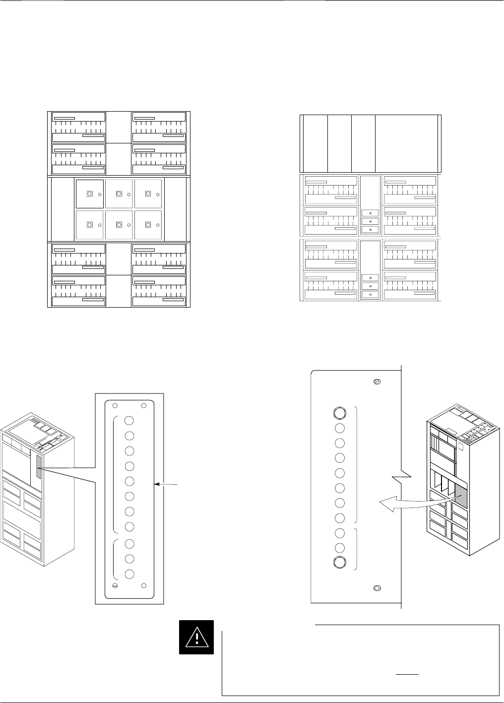
An overview of the BTS differences is illustrated in the following table
and in illustrations on the following pages (Figure 1-1 thru Figure 1-4).
SC4812T Description # Description SC4812T-MC
1
2
3x3 DC Power Input
(see Figure 1-1) 12x2 DC Power Input
(see Figure 1-1)
1
2
7
1
2
3
I/O Plate supporting
3x3 DC Power Input
(see Figure 1-2)
2I/O Plate supporting
2x2 DC Power Input
(see Figure 1-2)
1
2
3
7C–CCP Fan Tray 3C–CCP Speed–
Controlled Fan Tray
4C-CCP Cage:
SCIO (3- or
6-Sector)
SBBX-1X
SSwitch
4C-CCP Cage:
SMCIO (3- or 6-Sector)
SHigh Power BBX-1X
SHigh Power Switch
4
6
5
PA Shelves:
SSC 4812T LPA
S4x4 TX Backplane
SPA Location and
Mapping (see
Figure 1-3)
SShelf Qty: 1 for up
to 2 carriers; 2 for 3 or
more carriers.
5PA Shelves:
SSC 4812T CLPA
SMulticarrier module
S(Switched) Parallel Linear
amplifier Combiner
SEnhanced Trunking
Module
SLPA/PLC Filler Panel
SPA Location and Mapping
(see Figure 1-3)
SShelf Qty: 2 for all
configurations 56
7
2:1 or 4:1 Combiners
or Dual Bandpass TX
Filters
6TX Filters
and/or
TX Output Terminator
ti-CDMA-WP-00098-v01-ildoc-ftw PA Breaker Mapping
(see Figure 1-4) 7PA Breaker Mapping
(see Figure 1-4)
ti-CDMA-WP-00196-v01-ildoc-ftw
Read Me First: SCE4812T–MC to SCE4812T Comparison – continued
1-2 1X SC4812T–MC BTS Optimization/ATP 5/21/04
DRAFT
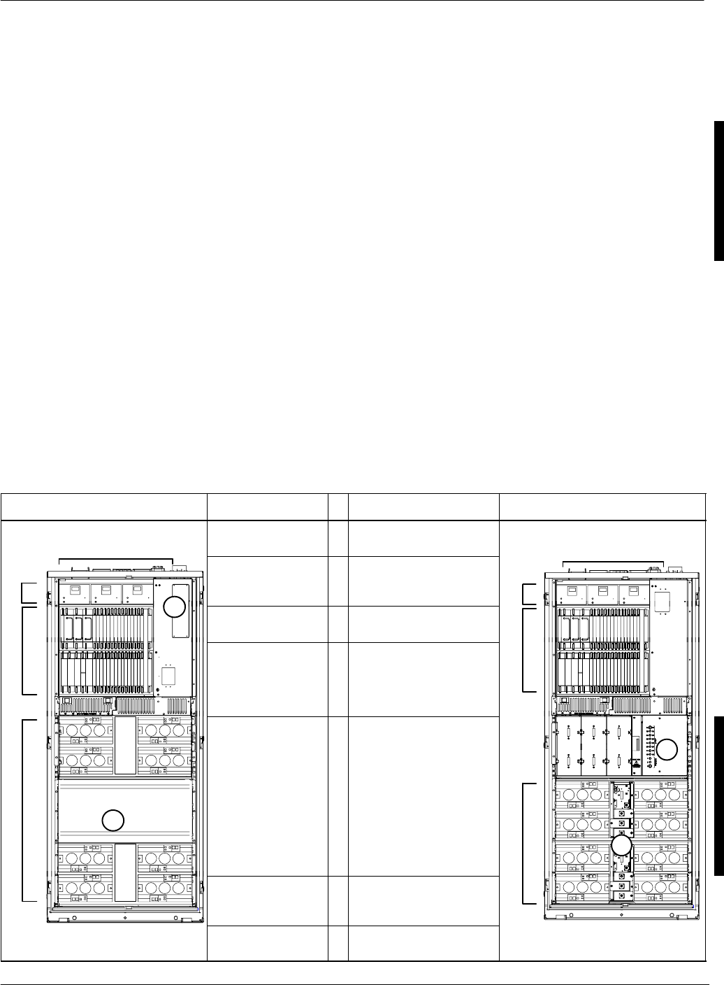
SC 4812T SC 4812T–MC
CABLE
GROMMET
(0509591Y02)
LUG COVER
(1509789V01)
M10 NUT
(0210971A09)
M10 LOCK WASHER
(0410985A02)
M10 FLAT WASHER
(0410983B28)
CRIMP LUG
FEED COVER
(DO NOT REMOVE)
ENCLOSURE
BASE
POWER
INPUT STUD
ti-CDMA-WP-00024-v01-ildoc-ftw
DC
CONTACT
Input
Connector/
DC Filter
ti-CDMA-WP-00074-v01-ildoc-ftw
DC
Connector
Housing
DC
CONTACT
(+) DC CABLE
DC CABLE (–)
(–)
(+)
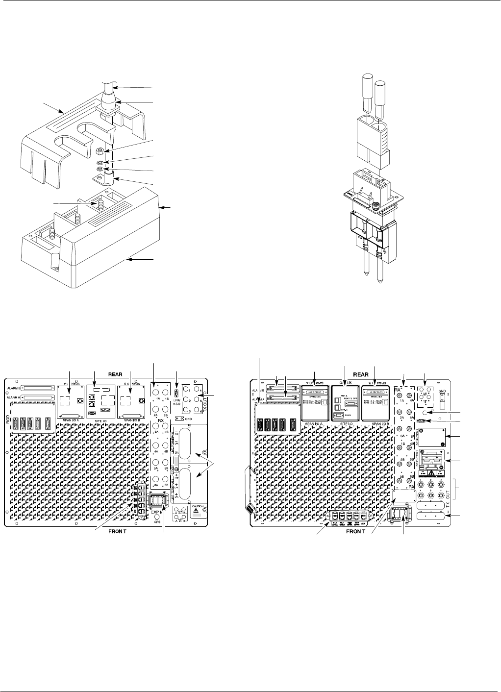
Figure 1-1: DC Power Input Connector Comparison
ETHERNET ROUTER (IF USED;
OTHERWISE, FILLER PLATE)
EXP IN FILLER
PLATE
RF EXPANSION PORT TO ANOTHER
BTS (USED ONLY IF EXPANSION
FRAME INSTALLED; OTHERWISE,
FILLER PLATE INSTALLED)
ti-CDMA-WP-00188-v01-ildoc-ftw
SPAN I/O
SITE I/O
ALARM
CONNECTORS
LAN
CONNECTIONS
GPS IN
HSO/LFR
FILLER PLATE
RECEIVE
ANTENNA
CONNECTORS
INPUT
CONNECTOR/
DC FILTER
SPAN I/O
REMOTE GPS DISTRIBUTION (RGD) MODULE –
USED ONLY IF EXPANSION FRAME(S) INSTALLED
PACKET
BACKHAUL PORTS RF EXPANSION PORT
(TO ANOTHER BTS)
LOW FREQUENCY
RECEIVER / HSO
SPAN I/O
TRANSMIT
ANTENNA
CONNECTORS
POWER
INPUT
RECEIVE ANTENNA
CONNECTORS
SITE I/OSPAN I/O
ti-CDMA-WP-00101-v01-ildoc-ftw
SC 4812T SC 4812T–MC
3 to 6 TX
ANTENNA
CONNECTORS
(depending on
configuration)
2 to 3 TX
ANTENNA
FILLER PLATES
(depending on
configuration)
Figure 1-2: I/O Plate Comparison
ESM
Read Me First: SCE4812T–MC to SCE4812T Comparison – continued
5/21/04 1X SC4812T–MC BTS Optimization/ATP 1-3
DRAFT
Numbering
LPA 1A
LPA 1B
LPA 1C
LPA 1D
LPA 3C
LPA 3A
LPA 3B
LPA 3D
LPA 2D
LPA 2C
LPA 2B
LPA 2A
LPA 4B
LPA 4A
LPA 4C
LPA 4D
Sector
3 Sector
Sector
3 Sector
(6 Sector)
Numbering
2 to 1 Combiner
3 Sector or 6 Sector
C1, S1–3
(C1, S1–3)
C2, S1–3
(C2, S1–3)
C3, S1–3
(C1, S4–6)
C4, S1–3
(C2, S4–6)
(6 Sector)
123
456
1C
2C
3C
4C
1D
2D
3D
4D
3A
2A
1A 1B
2B
3B
4B 4A
S4
MCM
1
Carrier
Numbering
Carrier
Numbering
3 Sector and 6 Sector 3 Sector
(6 Sector)
3 Sector
(6 Sector)
S5
S6
S1
S2
S3
MCM
2
CLPACLPA
CLPA
CLPA
CLPA
CLPA
CLPA
CLPA
CLPA
CLPA
CLPA
CLPA
CLPA
CLPA
CLPA
CLPA
SC 4812T SC 4812T–MC
FW00297 REF.
ti-CDMA-WP-00197-v01-ildoc-ftw
Figure 1-3: PA Location Comparison
NOTES:
SMCM CAN BE EITHER 3.3 OR 4X4
SMCM2 IS REQUIRED ONLY IN A 6–SECTOR CONFIGURATION
SLOWER RIGHT QUADRANT WILL ONLY HAVE CLPAS IN IT IN
A 4.4 CONFIGURATION
50
SC 4812T SC4812T–MC
L
P
A
C
C
C
P
2A
4A
2B
4B
2C
4C
2D
4D
1A
3A
1B
3B
1C
3C
1D
3D
50
1
2
3
50 50 50 50 50 50 50 50 50
ti-CDMA-WP-00224-v01-ildoc-ftw
CIRCUIT
BREAKER
PANEL
1D1C
2C 2D
1B
1A
2A 2B
30
30
30
30
30
30
30
30
3D3C
4C 4D
3B
3A
4A 4B
50
50
50
1
2
3
C
C
P
L
P
A
C
FW00380 REF.
Figure 1-4: PA Breaker Mapping Comparison
Each breaker controls a pair of PAs. In an SC4812T–MC,
opening (pulling) a PA breaker while the BTS is operating
will degrade the TX Output power of ALL sector–carriers,
not just a specific carrier as in an SC4812T.
CAUTION

Read Me First SCE4812T–MC to SCE4812T Optimization/ATP
1-4 1X SC4812T–MC BTS Optimization/ATP 5/21/04
DRAFT
General Test Procedural
Changes for SC 4812T-MC
The GENERAL information herein summarizes procedural
changes introduced with the SC 4812T–MC BTS. Detailed
procedures are provided in the Optimization and ATP
sections.
NOTE
1. During the execution of any TX tests or calibration
procedures, ALL Power Amplifiers (PA) must be in
service (INS).
2. When logging into a BTS with a system release earlier
than 2.16.4.x, be sure to set BTS type to MultiCarrier
in the dialog box which will appear when logging into
the BTS.
NOTE
Transmit (TX) Bay Level Offset (BLO) Specifications –
SC4812T–MC TX BLO specifications for different BTS sector
configurations are as follows:
S800 MHz Three–sector BTS:
– Single–sided BLO: >35dB
– Double–sided BLO: 40dB +/– 5dB
S800 MHz Six–sector BTS
– Single–sided BLO: >38dB
– Double–sided BLO: 43dB +/– 5dB
S1.9 GHz Three–sector BTS:
– Single–sided BLO: >30dB
– Double–sided BLO: 35dB +/– 5dB
S1.9 GHz Six–sector BTS
– Single–sided BLO: >33dB
– Double–sided BLO: 38dB +/– 5dB
Verifying Pilot Power Setting
with a Wide Band RF Power
Meter
The SC4812T–MC requires all equipped PAs be enabled during TX test.
With a “tuned” RF power meter, such as the Agilent VSA E4406A, all
sectors–carriers can be enabled simultaneously and each sector–carrier
power level setting can be measured. The following work–around
procedures are suggested when using a wide band RF power meter and
the BTS is under OMC–R control.
Read Me First SCE4812T–MC to SCE4812T Optimization/ATP – continued
5/21/04 1X SC4812T–MC BTS Optimization/ATP 1-5
DRAFT
This workaround is only required before system release
2.16.4.x. After release 2.16.4.x, any one BBX keyed will
enable all the CLPA modules.
NOTE
1–carrier configuration (requires 3 measurements) – The 1-carrier
procedure is identical to the current SC4812T, which is to enable all
three sector BBXs, then measure with each sector with the RF power
meter.
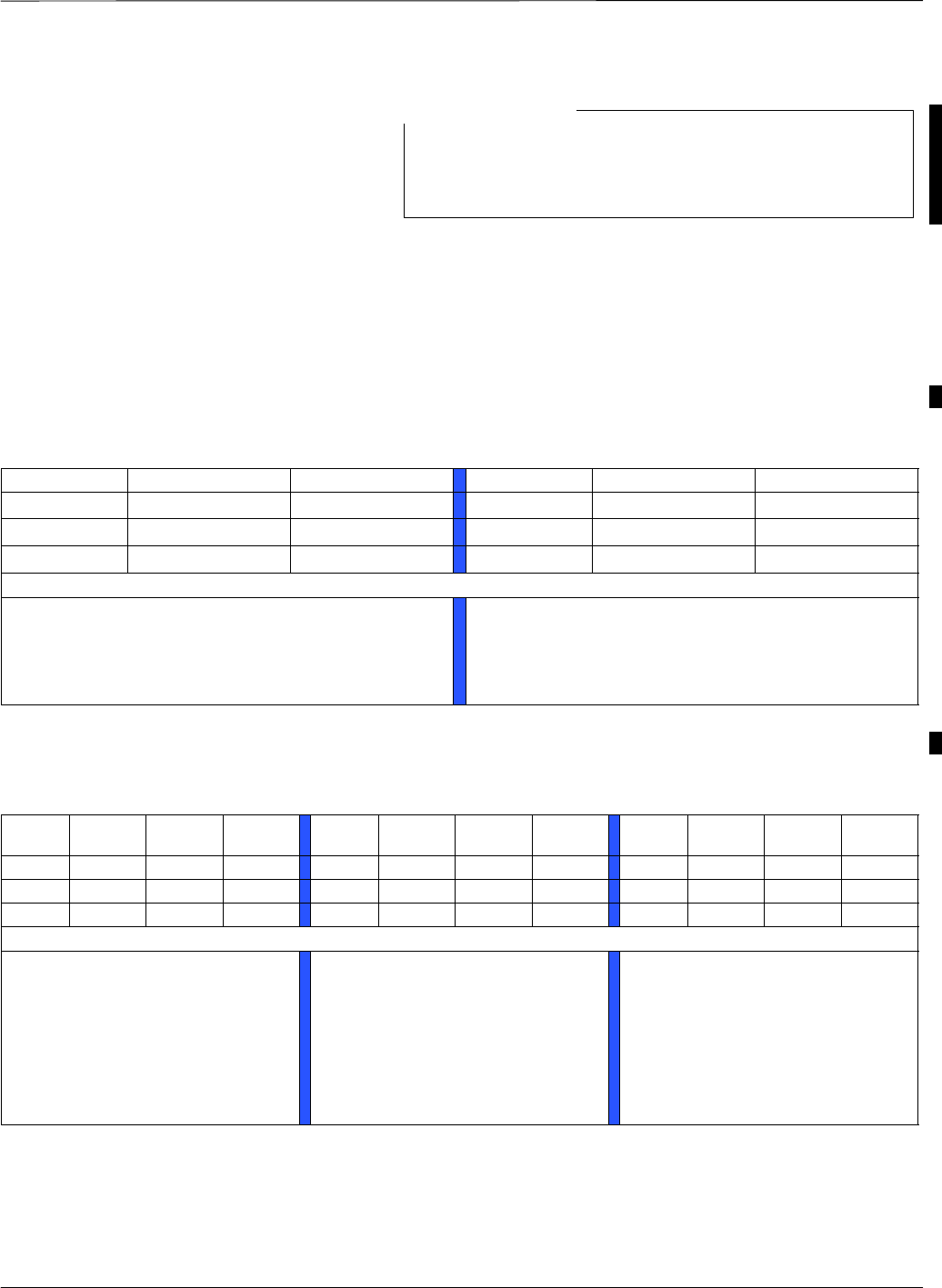
2–carrier configuration (requires 6 measurements) – The procedure
below allows taking measurements with both carriers enabled and more
than one carrier on same sector.
Sector Carrier 1 Carrier 2 Sector Carrier 1 Carrier 2
1 BBX-1 1 BBX-7
2 BBX-2 2 BBX-8
3 BBX-9 3 BBX-3
Procedure:
1. Enable BBX-1 (C1–S1), BBX-2 (C1–S2), and
BBX-9 (C2–S3).
2. Measure TX power from each of all 3 sectors.
3. Disable BBX-1, BBX-2, and BBX-9.
4. Enable BBX-3 (C1–S3), BBX-7 (C2–S1), and
BBX-8 (C2–S2).
5. Measure TX power from each of all 3 sectors.
6. Disable BBX-3, BBX-7, and BBX-8.
3–carrier configuration (requires 9 measurements) – The procedure
below allows taking measurements with all 3 carriers enabled and more
than one carrier on same sector.
Sector Carrier
1
Carrier
2
Carrier
3
Sector Carrier
1
Carrier
2
Carrier
3
Sector Carrier
1
Carrier
2
Carrier
3
1 BBX-1 1 BBX-4 1 BBX-7
2 BBX-8 2 BBX-2 2 BBX-5
3 BBX-6 3 BBX-9 3 BBX-3
Procedure:
1. Enable BBX-1 (C1–S1),
BBX8 (C2–S2), and BBX6
(C3–S3)
2. Measure TX power from each
of all 3 sectors
3. Disable BBX1, BBX8, and
BBX6
4. Enable BBX-2 (C1–S2),
BBX-9 (C2–S3), and BBX-4
(C3–S1)
5. Measure TX power from each
of all 3 sectors
6. Disable BBX-2, BBX-9, and
BBX-4
7. Enable BBX-3 (C1–S3),
BBX-7 (C2–S1), and BBX-5
(C3–S2)
8. Measure TX power from each
of all 3 sectors
9. Disable BBX-3, BBX-7, and
BBX-5
Read Me First SCE4812T–MC to SCE4812T Optimization/ATP – continued
1-6 1X SC4812T–MC BTS Optimization/ATP 5/21/04
DRAFT
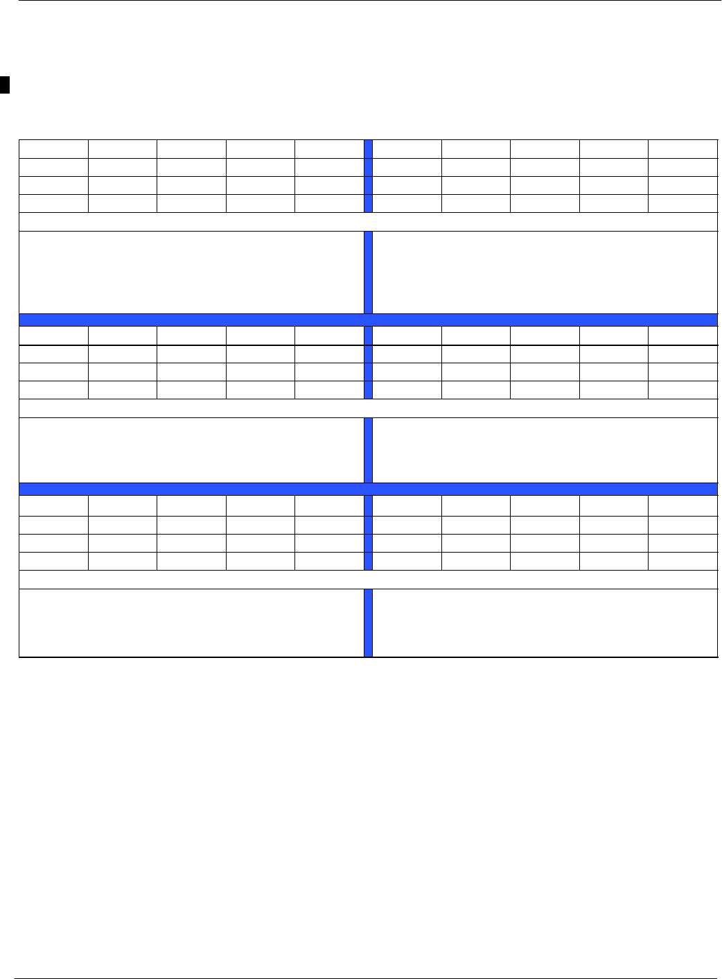
4–carrier configuration (requires 12 measurements) – Use this
procedure to take measurements with all 4 carriers enabled. The sector
with 2 carriers active will not be measured.
Sector Carrier 1 Carrier 2 Carrier 3 Carrier 4 Sector Carrier 1 Carrier 2 Carrier 3 Carrier 4
1 BBX-1 1 BBX-4 BBX-10
2 BBX-8 2 BBX-2
3 BBX-6 BBX-12 3 BBX-9
Procedure:
1. Enable BBX-1, BBX-8, BBX-6, and BBX-12.
2. Measure TX power from at sector 1 carrier 1
(C1-S1) and sector 2 carrier 2 (C2-S2).
3. Disable BBX-1, BBX-8, BBX-6, and BBX-12.
4. Enable BBX-2, BBX-9, BBX-4, and BBX-10.
5. Measure TX power of C1-S2 and C2-S3.
6. Disable BBX-2, BBX-9, BBX-4, and BBX-10.
Sector Carrier 1 Carrier 2 Carrier 3 Carrier 4 Sector Carrier 1 Carrier 2 Carrier 3 Carrier 4
1 BBX-7 1 BBX-1 BBX-7
2 BBX-5 BBX-11 2 BBX-5
3 BBX-3 3 BBX-12
Procedure:
7. Enable BBX-3, BBX-7, BBX-5, and BBX-11.
8. Measure TX power of C1-S3 and C2-S1.
9. Disable BBX-3, BBX-7, BBX-5, and BBX-11.
10.Enable BBX-1, BBX-7, BBX-5, and BBX-12.
11.Measure TX power of C3-S2 and C4-S3.
12.Disable BBX-1, BBX-7, BBX-5, and BBX-12.
Sector Carrier 1 Carrier 2 Carrier 3 Carrier 4 Sector Carrier 1 Carrier 2 Carrier 3 Carrier 4
1 BBX-10 1 BBX-4
2 BBX-2 BBX-8 2 BBX-11
3 BBX-6 3 BBX-3 BBX-9
Procedure:
13.Enable BBX-2, BBX-8, BBX-6, and BBX-10.
14.Measure TX power of C3-S3 and C4-S1.
15.Disable BBX-2, BBX-8, BBX-6, and BBX-10.
16.Enable BBX-3, BBX-9, BBX-4, and BBX-11.
17.Measure TX power C3-S1 and C4-S2.
18.Disable BBX-3, BBX-9, BBX-4, and BBX-11.

Read Me First SCE4812T–MC to SCE4812T Optimization/ATP – continued
5/21/04 1X SC4812T–MC BTS Optimization/ATP 1-7
DRAFT
2–carrier, 6–sector configuration (requires 12 measurements) – Use
this procedure to take measurements with both carriers enabled.
Sector Carrier 1 Carrier 2 Sector Carrier 1 Carrier 2
1 BBX-1 1 BBX-7
2 BBX-2 2 BBX-8
3 BBX-9 3 BBX-3
4 BBX-4 4 BBX-10
5 BBX1–11 5 BBX-5
6 BBX1–12 6 BBX-6
Procedure:
1. Enable the following BBXs:
– BBX-1 (C1–S1)
– BBX-2 (C1–S2)
– BBX-4 (C1-S4)
– BBX-9 (C2–S3)
– BBX-11 (C2-S5)
– BBX-12 (C2-S6)
2. Measure TX power from each of all 6 sectors.
3. Disable BBXs.
4. Enable the following BBXs:
– BBX-3 (C1–S3)
– BBX-5 (C1-S5)
– BBX-6 (C1-S6)
– BBX-7 (C2–S1)
– BBX-8 (C2–S2)
– BBX-10 (C2-S4)
5. Measure TX power from each of all 6 sectors.
6. Disable BBXs.

Scope, Assumptions, and Audience
1-8 1X SC4812T–MC BTS Optimization/ATP 5/21/04
DRAFT
1. Procedures in this manual apply to an SC4812T–MC
BTS operating with Dynamic Multi–Carrier PA
Control under Motorola Software Release 2.16.4.1 and
later. These procedures will not work for an
SC4812T–MC BTS operating with Motorola Software
Release 2.16.4.0 and earlier.
2. Procedures in this manual require the use of Local
Maintenance Facility (LMF) application software
version 2.16.4.0.09 or later.
CAUTION
Scope
This publication provides information pertaining to the optimization and
acceptance tests of the SC"4812T–Multi–Carrier Base Transceiver
Subsystem (1X SC4812T–MC BTS). The following models equipped
with trunked Power Amplifiers (PA) and their associated internal and
external interfaces are covered:
S800 MHz models ST1407/ST1408
S1.9 GHz models ST1426/ST1428
Circuit and Packet BTS
Support
Information in this publication supports optimization and calibration of
the following types of BTS sites operating with Motorola Software
Release 2.16.4.1 and later:
S1X circuit BTS
S1X packet BTS
The cdma2000 1X (1X) packet BTS has a packet backhaul network
interface provided through BTS routers operating with a
Third–generation Group Line Interface (GLI3) card that can support
voice (IS-95A/B, 1X) and data (IS-95B, 1X).
This BTS equipment may be configured with all 1X cards (BBX–1X and
MCC–1X) or a mix of 1X cards and non–1X cards (BBX2 and
MCC8E/24E). This configuration is compliant with all applicable 1X
specifications. It provides the forward link and reverse link RF functions
to support Second Generation (2G) features and Third Generation (3G)
1X features; that is, high capacity voice and high bit–rate data.
The 1X circuit BTS is capable of using a split or mixed backhaul
(circuit/packet pipe) network interface that can handle circuit–based
voice (IS-95A/B, 1X) and data (IS-95B) as well as “packetized” data
(1X).
1

Scope, Assumptions, and Audience – continued
5/21/04 1X SC4812T–MC BTS Optimization/ATP 1-9
DRAFT
Assumptions
This document assumes that the BTS frames and cabling have been
installed according to the following manuals:
SSC Product Family Frame Mounting Guide, which covers the physical
“bolt down” of all SC series equipment frames
S1X SC 4812T-MC BTS Hardware Installation , which covers BTS
specific cabling configurations for Packet Backhaul and the addition
of carriers to the BTS
Audience
Motorola Technical Information Products and Services (TIPS) has
attempted to incorporate into this document the many customer
suggestions and inputs received since the inception of the SC product
line. At the same time, TIPS has tried to ensure that the scope of the
document targets both the novice and expert site technician and
engineer with the information required to successfully perform the
task at hand. If, in some areas, the manual seems to cover the subject in
too much or not enough detail, please keep this in mind.
Intended Reader Profile
The information in this manual set is intended for use by the cellular
communications craftsperson(s) in the initial installation and
configuration, as well as the day-to-day operation and maintenance of a
BTS.
The user of this information has a general understanding of telephony, as
used in the operation of the Public Switched Telephone Network
(PSTN), and is familiar with these concepts as they are applied in the
cellular and maintenance mobile/portable radiotelephone environment.
The user also needs a working knowledge of MSr Windows#98$or
Windows 2000%.
1

Content Summary
1-10 1X SC4812T–MC BTS Optimization/ATP 5/21/04
DRAFT
Publication Composition
This publication covers the following areas.
SIntroduction: preliminary background information (such as
component and subassembly locations and frame layouts) to be
considered by the Cellular Field Engineer (CFE) before optimization
or tests are performed.
SPreliminary Operations: jumper configuration of BTS sub–assemblies,
pre–power up tests, initial power application and power–up tests for
the BTS equipment frame after installation, and download of all BTS
processor boards and PAs.
SOptimization/Calibration: downloading all BTS processor boards, test
equipment set–up and calibration, PA verification, radio frequency
(RF) path verification, Bay Level Offset (BLO) calibration, Cellular
Radio Monitoring System (CRMS), and Radio Frequency Diagnostic
System (RFDS) functions and calibration.
SAcceptance Test Procedures (ATP): automated ATP scripts executed
by the LMF and used to verify all major transmit (TX) and receive
(RX) performance characteristics on all BTS equipment. Includes
generating an ATP report.
SPrepare to Leave the Site: site turnover process after ATP is
completed.
SBasic Troubleshooting: procedures to perform when an ATP fails, as
well as when incorrect results are obtained during logon, test
equipment operation, calibration, and Global Positioning System
(GPS) operation. These tests are typically used to isolate faults down
to the module level. Also provided is additional information necessary
to better understand equipment operation.
SAppendices that contain pertinent data sheets that are filled out
manually by the CFE at the site, Pseudorandom Noise (PN) Offset
information, an optimization/ATP matrix , output power data tables,
CDMA operating frequency programming information, manual test
setup information, procedures for verifying that the Voltage Standing
Wave Ratio (VSWR) of all antennas and associated feed lines fall
within acceptable limits, and procedures for downloading ROM and
RAM code.
1

Purpose of Optimization
5/21/04 1X SC4812T–MC BTS Optimization/ATP 1-11
DRAFT
Why Optimize?
Proper optimization and calibration ensures that:
SAccurate downlink RF power levels are transmitted from the site.
SAccurate uplink signal strength determinations are made by the site.
What Is Optimization?
Optimization compensates for the site-specific cabling and normal
equipment variations. Site optimization guarantees that the combined
losses of the cables and the gain/loss characteristics and built-in
tolerances of each BTS frame do not accumulate and cause improper site
operation.
What Happens During
Optimization?
Overview – During optimization, the accumulated path loss or gain is
first determined for each RF transmit path in the BTS. These transmit
path loss or gain values are then stored in a database along with RF
receive path default values.
RF path defintions – For definitions of the BTS transmit (TX) and
receive (RX) paths, see “What is Bay Level Offset Calibration?” in the
Bay Level Offset Calibration section of Chapter 3.
In this publication, all models of the Broad Band
Transceiver (BBX) board usable in this BTS, are
generically identified as BBX, unless otherwise specified.
Also, all models of the Multi–Channel CDMA (MCC)
cards usable in this BTS, are generically identified as
MCC, unless otherwise specified.
NOTE
RF paths and transceiver optimization – Twelve of the BBX boards in
each Combined–CDMA Channel Processor (C–CCP) shelf are
optimized to specific RX and TX antenna connectors. The last BBX
board provides redundancy for BBX boards 1 through 12, and is
optimized to all antenna connectors. A single optimization value is
generated for each complete path. This eliminates the accumulation of
error that would occur from individually measuring and summing the
gain and loss of each element in the path.
Using RF path gain/loss values – BTS equipment factors in the derived
optimization values internally to adjust transceiver power levels, leaving
only site–specific antenna feedline loss and antenna gain characteristics
to be factored in by the CFE when determining required site Effective
Radiated Power (ERP) output power levels.
1

When to Optimize
1-12 1X SC4812T–MC BTS Optimization/ATP 5/21/04
DRAFT
New Installations
The following operations and optimization/test actions should be
accomplished for a new BTS or frame installation:
1. After the initial site installation, the BTS must be prepared for
operation. This preparation includes verifying hardware installation,
initial power–up, downloading of operating code, verifying GPS
operation, and verifying transmit and receive paths.
2. Next, the optimization is performed. Optimization includes
performance verification and calibration of all transmit and receive
RF paths, and download of accumulated calibration data.
3. A calibration audit of all RF transmit paths may be performed any
time after optimization to verify BTS calibration.
4. After optimization, a series of manual pre–Acceptance Test
Procedure (ATP) verification tests are performed to verify
alarm/redundancy performance.
5. After manual pre–ATP verification tests, an ATP is performed to
verify BTS performance. An ATP is also required to demonstrate
regulation compliance before the site can be placed in service.
Site Expansion
Optimization is also required after expansion of a site with additional
BTS frames.
Periodic Optimization
Periodic optimization of a site may also be required, depending on the
requirements of the overall system.
Repaired Sites
Refer to Appendix C for a detailed FRU Optimization/ATP Test Matrix
outlining the minimum tests that must be performed any time a BTS RF
subassembly or cable associated with an RF path is replaced.
1

Test Equipment Selection, Calibration, and General Operation
Requirememnts
5/21/04 1X SC4812T–MC BTS Optimization/ATP 1-13
DRAFT
Policy
General Requirements – To ensure consistent, reliable, and repeatable
optimization test results, test equipment and software meeting the
following technical criteria should be used to optimize the BTS
equipment.
Test equipment substitution – Test equipment can, of course, be
substituted with other test equipment models but those models must
meet the same technical specifications. All test equipment models
selected for use in BTS calibration and acceptance testing must be
supported by the LMF..
Measurement variances and test equipment substitution – It is the
responsibility of the customer to account for any measurement variances
and/or additional losses/inaccuracies that can be introduced as a result
of test equipment model substitutions. Before beginning optimization or
troubleshooting, make sure that the test equipment needed is on–hand
and operating properly.
Test Equipment Calibration
Optimum system performance and capacity depend on regular equipment
service and calibration prior to BTS optimization. Follow the original
equipment manufacturer (OEM) recommended maintenance and
calibration schedules closely.
Test Cable Calibration
On–site cable calibration – Test cables can make critical differences in
optimization accuracy. It is recommended that cable calibration be run at
every BTS with the complete test equipment set. This method
compensates for test cable insertion loss within the test equipment set
itself. No other allowance for test cable insertion loss needs to be made
during the performance of BTS calibration or acceptance tests.
In–shop cable characterization – Another method to account for cable
loss is by entering it into the LMF during the optimization procedure.
This method requires accurate test cable characterization using shop test
equipment. Characterized cables should be tagged with the
characterization information, and the measured losses entered into the
LMF before field optimization.
Equipment Warm–up
After arriving at the a site, the test equipment should be plugged in and
turned on to allow warm up and stabilization to occur for as long as
possible. The following pieces of test equipment must be warmed–up for
a minimum of 60 minutes prior to using for BTS optimization
procedures.
SCommunications Test Set
SPower Meter
1

Required Test Equipment and Software
1-14 1X SC4812T–MC BTS Optimization/ATP 5/21/04
DRAFT
Overview
Test equipment and software described in this section is required for the
optimization and acceptance testing procedures. Common tools such as
screwdrivers and frame keys are also needed. Read the operators manual
for all test equipment items to understand their individual operation
before using them for optimization or acceptance testing.
LMF Computer and Software
LMF Hardware Requirements
An LMF computer platform that meets the following requirements (or
better) is recommended:
SNotebook computer
S266 MHz (32–bit CPU) Pentium processor
SWindows 98 Second Edition (SE) or Windows 2000 operating system
S4 GB internal hard disk drive
SSVGA 12.1–inch active matrix color display with 1024 x 768
(recommended) or 800 x 600 pixel resolution and capability to display
more than 265 colors
NOTE If 800 x 600 pixel resolution is used, the LMF window must be
maximized after it is displayed.
SMemory requirements:
– Minimum required RAM: 96 MB
– Recommended RAM:
–– 128 MB for Windows 98 SE
–– 256 MB for Windows 2000
S20X CD ROM drive
S3 1/2 inch floppy drive
S56kbps V.90 modem
SSerial port (COM 1)
SParallel port (LPT 1)
SPCMCIA Ethernet interface card (for example, 3COM Etherlink III)
with a 10Base–T–to–coax adapter
1

Required Test Equipment and Software – continued
5/21/04 1X SC4812T–MC BTS Optimization/ATP 1-15
DRAFT
LMF Software
The Local Maintenance Facility (LMF) application program is a
graphical user interface (GUI)–based software tool. This product is
specifically designed to provide cellular communications field personnel
with the capability to support the following CDMA BTS operations:
SInstallation
SMaintenance
SCalibration
SOptimization
Ethernet LAN Transceiver
SPCMCIA Ethernet Adpater + Ethernet UTP Adapter: 3COM Model –
Etherlink III 3C589B
10BaseT/10Base2 Converter
STransition Engineering Model E–CX–TBT–03 10BaseT/10Base2
Converter
NOTE Xircom Model PE3–10B2 or equivalent can also be used to
interface the LMF Ethernet connection to the frame.
3C–PC–COMBO CBL
SConnects to the 3COM PCMCIA card and eliminates the need for a
10BaseT/10base2 Converter.
RS–232 to GPIB Interface
SNational Instruments GPIB–232–CT with Motorola CGDSEDN04X
RS232 serial null modem cable or equivalent; used to interface the
LMF to the test equipment.
SStandard RS–232 cable can be used with the following modifications
(see Figure 1-5):
– This solution passes only the 3 minimum electrical connections
between the LMF and the General Purpose Information Bus (GPIB)
interface. The control signals are jumpered as enabled on both ends
of the RS–232 cable (9–pin D). TX and RX signals are crossed as
Null Modem effect. Pin 5 is the ground reference.
– Short pins 7 and 8 together, and short pins 1, 4, and 6 together on
each connector.
5
3
2
7
8
1
4
6
GND
RX
TX
RTS
CTS
RSD/DCD
DTR
GND
TX
RX
RTS
CTS
RSD/DCD
DTR
ON BOTH CONNECTORS:
SHORT PINS 7 and 8;
SHORT PINS 1, 4, and 6
9–PIN D–FEMALE 9–PIN D–FEMALE
5
2
3
7
8
1
4
6
DSR DSR
FW00362
Figure 1-5: Null Modem Cable Detail
1

Required Test Equipment and Software – continued
1-16 1X SC4812T–MC BTS Optimization/ATP 5/21/04
DRAFT
MMI Interface
Motorola cable part number CGDSMMICABLE219112 or a cable
locally fabricated as described in Appendix J is used to connect the LMF
to the BTS.
Communications System
Analyzer CDMA/analog
Table 1-1: CDMA LMF Test Equipment Support Table
Item Description Test Capability
Test Sets
Hewlett Packard, model
HP 8921A (with 83203B)
Communications analyzer (includes 83203B
CDMA interface option)
IS–95A/B only
Hewlett Packard, model
HP 83236A
PCS interface for PCS band IS–95A/B only
Motorola CyberTest Communications analyzer IS–95A/B only
Advantest R3465 (with 3561L) Communications analyzer (with 3561 CDMA
option)
IS–95A/B only
Agilent E4406A (with E4432B) Communications analyzer (with Generator) IS–95A/B and
CDMA 2000 testing
Advantest R3267 Analyzer (with
R3562)
Communications Analyzer with Advantest
R3562 Generator
IS–95A/B and
CDMA 2000 testing
Agilent 8935 series E6380A
(formerly HP 8935) with option
200 or R2K
Communications test set IS–95A/B and
CDMA 2000 testing
Agilent E7495A Communications test set IS–95A/B and
CDMA 2000 testing
Power Meters
Gigatronix 8541C Power meter
HP437B (with HP8481A sensor) Power meter with sensor – capable of measuring –30 dBm to 20 dBm
A combination of test equipment supported by the LMF may also be
used during optimization and testing of the RF communications portion
of BTS equipment when the communications system analyzer does not
perform all of the following functions:
SFrequency counter
SDeviation meter
SRF power meter (average and code domain)
SRF signal generator (capable of DSAT/CDMA modulation)
SAudio signal generator
SAC voltmeter (with 600–ohm balanced audio input and high
impedance input mode)
SNoise measurement meter
1

Required Test Equipment and Software – continued
5/21/04 1X SC4812T–MC BTS Optimization/ATP 1-17
DRAFT
SC–Message filter
SSpectrum analyzer
SCDMA code domain analyzer
GPIB Cables
SHewlett Packard 10833A or equivalent; 1 to 2 meters (3 to 6 feet) long
used to interconnect test equipment and LMF terminal.
Timing Reference Cables
STwo BNC-male to BNC-male RG316 cables; 3.05 m (10 ft.) long.
Used to connect the communications analyzer to the front timing
reference of the CSM cards in the BTS frame.
Digital Multimeter
SFluke Model 8062A with Y8134 test lead kit or equivalent; used for
precision dc and ac measurements, requiring 4–1/2 digits.
Directional Coupler
SNarda Model 30445 30 dB (Motorola Part No. 58D09643T01 )
800 MHz coupler terminated with two Narda Model 375BN–M loads,
or equivalent.
RF Terminations/Loads
SAt least three 100–Watt (or larger) non–radiating RF
terminations/loads.
Miscellaneous RF Adapters, Loads, etc
SAs required to interface test cables and BTS equipment and for
various test set ups. Should include at least two 50 Ohm loads (type
N) for calibration and one RF short, two N–Type Female–to–Female
Adapters.
LAN Cable
SBNC–to BNC 50 ohm coaxial cable [.91 m (3 ft) maximum] with an
F–to–F adapter, used to connect the 10BaseT–to–coaxial adapter to
the BTS LAN connector.
High–impedance Conductive Wrist Strap
SMotorola Model 42–80385A59; used to prevent damage from
Electrostatic Discharge (ESD) when handling or working with
modules.
1

Required Test Equipment and Software – continued
1-18 1X SC4812T–MC BTS Optimization/ATP 5/21/04
DRAFT
Optional Equipment
Not all optional equipment specified here will be supported
by the LMF in automated tests or when executing various
measure type command line interface (CLI) commands. It
is meant to serve as a list of additional equipment that
might be required during maintenance and troubleshooting
operations.
NOTE
Frequency Counter
SStanford Research Systems SR620 or equivalent. If direct
measurement of the 3 MHz or 19.6608 MHz references is required.
Spectrum Analyzer
SSpectrum Analyzer (HP8594E with CDMA personality card) or
equivalent; required for manual tests.
Local Area Network (LAN) Tester
SModel NETcat 800 LAN troubleshooter (or equivalent); used to
supplement LAN tests using the ohmmeter.
Span Line (T1/E1) Verification Equipment
SAs required for local application
Oscilloscope
STektronics Model 2445 or equivalent; for waveform viewing, timing,
and measurements or during general troubleshooting procedure.
2–way Splitter
SMini–Circuits Model ZFSC–2–2500 or equivalent; provides the
diversity receive input to the BTS
High Stability 10 MHz Rubidium Standard
SStanford Research Systems SR625 or equivalent – required for CSM
and Low Frequency Receiver/High Stability Oscillator (LFR/HSO)
frequency verification.
Itasca Alarms Test Box
SItasca CGDSCMIS00014 – This test box may be used as a tool to
assist in the testing of customer alarms.
1

Required Documents and Related Publications
5/21/04 1X SC4812T–MC BTS Optimization/ATP 1-19
DRAFT
Required Documents
The following documents are required to perform optimization of the
cell site equipment:
SSite Document (generated by Motorola Systems Engineering), which
includes:
– General site information
– Floor plan
– RF power levels
– Frequency plan (includes Site PN and operating frequencies)
– Channel allocation (paging, traffic, etc.)
– Board placement
– Site wiring list
–Site–specific CDF file
SDemarcation Document (Scope of Work Agreement)
SEquipment manuals for non-Motorola test equipment
Related Publications
Additional, detailed information about the installation, operation, and
maintenance of the 1X SCt4812T–MC BTS and its components is
included in the following publications:
SLMF Help function on–line documentation
S1X SC 4812T-MC BTS Hardware Installation – 68P09260A38
S1X SC 4812T-MC BTS FRU Guide – 68P09260A87
S1X SC 4812T/ET/ET Lite/MC/T Lite BTS Troubleshooting Manual ;
68P09258A73 (packet) and 68P09258A74 (circuit)
SLMF On-Line Help, Software Release 2.16.4.x – 68P09260A45
SLMF CDMA CLI Reference, Software Release 2.16.4.x –
68P09260A67
SMWR1900 Wireless Mobile Edge Router Hardware Installation
Guide; part number 78–13982–01
SMWR1900 Wireless Mobile Edge Router Software Configuration
Guide; part number 78–13983–01
SMWR1941–DC Mobile Wireless Edge Router Hardware Installation
Guide; part number 78–15827–01
1

Terms and Abbreviations
1-20 1X SC4812T–MC BTS Optimization/ATP 5/21/04
DRAFT
Standard and Non–standard
Terms and Abbreviations
Standard terms and abbreviations used in this manual are defined in
Glossary of Cellular Terms; 68P09213A95 and Cellular Acronyms;
68P09301A61. Any non–standard terms or abbreviations included in this
manual are listed in Table 1-2.
Table 1-2: Non–Standard Terms and Abbreviations
Term or Abbreviation Definition
1X One of two bandwidths currently defined in the IS–2000 CDMA specification,
which extends the capability of the IS–95A and B specifications. 1X bandwidth
provides wireless packet voice and data transmission capability at up to 144
Mbps.
BPR BTS Packet Router. Markings on GLI3 Fast Ethernet connectors and SC4812T
Fast Ethernet interface housing.
AR As Required
BSS Base Station Subsystem (BSS). The BSS consists of a Radio Access Network
(RAN), at least one Access Node (AN), and a pair of core routers. It may also
include a Digital Access Crossconnect System (DACS) to support split backhaul
and, under Software Release 2.16.1.x and higher, a Selector Distribution Unit
(SDU).
BTSRTR BTS RouTeR (see BTS router)
BTSRTRGRP BTS RouTeR GRouP (see BTS router group)
BTS router One of the routers in a BTS router group.
BTS router group The single non–redundant router or redundant router pair required for network
interface when a BTS is operating on packet backhaul.
cage Used interchangeably with “shelf” in SC4812T/ET/ET Lite BTSs, as in
Combined CDMA Channel Processor shelf.
canned configuration See minimum standard configuration.
C–CCP Combined–CDMA Channel Processor. CDMA cage type used by SC4812T and
SC4812ET BTSs where assemblies previously mounted in a BTS distribution
shelf are combined into the CCP cage.
CEPT Conference of European Postal and Telecommunications Administrators
CF Compact Flash. Type of flash memory card used in the BTS router to store the
Internetwork Operating System and configuration files.
CNEOMI Common Network Element Operation & Maintenance Interface
table continued on next page
1

Terms and Abbreviations – continued
5/21/04 1X SC4812T–MC BTS Optimization/ATP 1-21
DRAFT
Table 1-2: Non–Standard Terms and Abbreviations
Term or Abbreviation Definition
CRMS Cellular Radio Monitoring System
circuit backhaul Conventional, non–Internet Protocol (IP) backhaul between the BTS and the
Central Base Station Controller (CBSC) transcoder (XC) which carries IS–95A/B
traffic.
duplex router See redundant router
ESM Ethernet Surge Module
external BTS router MWR 1900 or MWR 1941 BTS routers mounted outside the C–CCP or SCCP
cage of a packet BTS.
FE Fast Ethernet. 100base–T mode of 10/100base–T Ethernet used for transmitting
packetized control and bearer traffic between the BTS router group and GLI3
cards in the BTS.
GLI3 Third generation Group Line Interface card. Replaces GLI2 cards in a BTS when
upgrading to packet backhaul capability under Software Release 2.16.1.x.
Provides all the functionality of GLI2 cards plus additional capabilities needed for
packet backhaul. GLI3 cards may only be installed in BSSs operating with
Software Release 2.16.1.x software.
high availability BTS
router
See redundant router.
IBR Integrated BTS Router; see integrated BTS router
Integrated BTS Router A GLI3 card loaded with bootROM code which allows the card’s controller for
Concentration Interface Highway (CHI) bus 2 to function as a router for packet
traffic for the BTS. Employing IBRs permits converting a BTS to packet backhaul
operation without using an external BTS router group. IBRs can operate as
non–redundant or redundant BTS routers, but their employment limits BTS span
capacity to one span as opposed to four spans for external BTS routers.
IOS Internetwork Operating System. Operating system software used by the external
BTS routers.
minimum standard
configuration
The initial minimum configuration data which must be loaded into a BTS router
to enable it to communicate on the network. This standard “canned configuration”
is generated by a script included in the R16.1 software load for the
OMC–R/CBSC. Separate configuration files for the primary BTS router on each
FE LAN at a site is created by the script and can be copied to the Compact Flash
(CF) memory card containing the IOS for BTS routers. Once the CF card with the
IOS and minimum standard configuration is installed, the BTS router can
communicate with the OMC–IP and the full, site–specific router configuration file
can be downloaded from the Mobile Wireless Center to the router. Different
configuration files are required for circuit and packet backhaul operation.
mixed backhaul See split backhaul.
table continued on next page
1

Terms and Abbreviations – continued
1-22 1X SC4812T–MC BTS Optimization/ATP 5/21/04
DRAFT
Table 1-2: Non–Standard Terms and Abbreviations
Term or Abbreviation Definition
MWC Mobile Wireless Center. One element of the OMC–IP which provides
management and control for the MWR 1900 or MWR 1941 BTS routers installed
in BTSs operating on packet backhaul.
non–redundant router A BTS router group consisting of a single router without redundancy used as a
cost–reduced network interface for a BTS operating on packet backhaul.
original design frame +27 Vdc and –48 Vdc BTS frames in produced during early production of the
product including starter and expansion frames. The FE Housing present on these
frames is not located in the front middle of the top I/O panel, but located in
different locations towards the rear of the unit, or on the right front side of the
unit. +27 Vdc frames are 1800mm, –48 Vdc frames are 2100mm. Refer to the +27
Vdc or –48 Vdc Differences sections for a visual explanation of original
production frames.
packet backhaul IP–based backhaul between the BTS and the the network. Packet backhaul
capability is implemented in Software Release 2.16.1.x and requires equipping a
BTS with BTS routers and GLI3 cards. With the packet backhaul upgrade, a BTS
can be configured for circuit operation with the capability to switch to packet
backhaul or for packet–only operation.
packet BTS A BTS operating on packet backhaul
pBTS Packet BTS
R15.x Motorola Software Release 2.15.0.39.10 or later. The version of the software
which must be installed on BSS equipment to allow upgrading to Software
Release 2.16.0.x.
R16.0 Motorola Software Release 2.16.0.x. The version of the software which must be
loaded on BSS equipment to upgrade it to software release 2.16.1.x.
R16.1 Motorola Software Release 2.16.1.x. The earliest software release supporting
packet backhaul.
redundant router A BTS router group consisting of two MWR 1900 or MWR 1941 routers with
Hot Standby Router Protocol (HSRP) to provide redundancy.
SC4812TX An expansion frame version of the SC4812T–series BTS equipped with trunked
RF power amplifiers and no receiver antenna ports.
C–CCP Combined – CDMA Channel Processor
ROMmon Low–level operating system used in MWR 1900 or MWR 1941 routers along
with the IOS
simplex router See non–redundant router.
table continued on next page
1

Terms and Abbreviations – continued
5/21/04 1X SC4812T–MC BTS Optimization/ATP 1-23
DRAFT
Table 1-2: Non–Standard Terms and Abbreviations
Term or Abbreviation Definition
split backhaul Backhaul serving a network in which IS–95A/B traffic and 1X data traffic are
mixed on circuit backhaul from CDMA2000 1X BTSs. 1X data traffic is “split”
from IS–95A/B on a single span by being transported on DS0 time slots dedicated
to a “packet pipe.” IS–95A/B traffic is transported on the remaining DS0 time
slots. Split backhaul on a single span must be connected to a Digital Access and
Cross–connect System (DACS) which directs IS–95A/B traffic to the CBSC XC
and 1X data traffic to the Access Node (AN), as required. If a DACS is not used, a
CDMA2000 1X BTS must be equipped with separate spans for 1X data packet
and IS–95A/B voice/data traffic, respectively. The 1X data packet–dedicated span
would connect directly to the AN. The IS–95A/B–only span would connect
directly to the CBSC XC.
tftp trivial file transfer protocol
updated design frame +27 Vdc and –48 Vdc BTS frames that contain enhancements of the BTS product
and include starter and expansion frames. The FE Housing present on these
frames is located in the front middle of the top I/O panel. Both the +27 Vdc and
the –48Vdc frames are 1800mm (original –48 Vdc frames are 2100mm).Another
visual reference that helps determine the frame at the site is the location of the
circuit breakers. The updated design frame provides the cage circuit breakers in
the middle right section of the frame. Refer to the +27 Vdc or –48 Vdc
Differences sections for a visual explanation of original production frames.
Var. Variable
WIC WAN Interface Card (also VWIC)
1

BTS Equipment Identification
1-24 1X SC4812T–MC BTS Optimization/ATP 5/21/04
DRAFT
Equipment Overview
The BTS can consist of the following equipment frames:
SAt least one BTS starter frame –
–48 V configuration shown in Figure 1-6
+27 V configuration shown in Figure 1-7
SAncillary equipment frame (or wall mounted equipment)
SOne or more Expansion frames (see Figure 1-8 and Figure 1-9).
Expansion frames are essentially the same as starter frames but
incorporate unique components on the I/O (Interconnect) panel.
I/O panel detail is provided for Starter Frame in
Figure 1-12 and Expansion Frame in Figure 1-13
C–CCP cage details are provided in Figure 1-14
NOTE
Logical BTS
The BTS software implements the logical BTS capability. Previously, all
BTS frames co–located at a single site had to be identified in the
network with separate and distinct BTS ID numbers. In the Logical BTS
feature, all frames located at a single BTS site are identified with unique
Frame ID numbers (Frame ID Numbers 1, 101, 201, 301) under a single
(site) BTS ID number. A logical BTS can consist of up to four frames.
When the LMF is connected to frame 1 of a logical BTS, you can access
all devices in all of the frames that make up the logical BTS. A logical
BTS requires a CDF file that includes equipage information for all of the
logical BTS frames and their devices and a CBSC file that includes
channel data for all of the logical BTS fames.
Logical BTS Numbering
The first frame of a logical BTS has a –1 suffix (e.g., BTS–812–1).
Other frames of the logical BTS are numbered with suffixes, –101, –201,
and –301 (e. g. BTS–812–201). When you log into a BTS, a FRAME
tab is displayed for each frame. If there is only one frame for the BTS,
there is only one tab (e.g., FRAME–282–1) for BTS–282. If a logical
BTS has more than one frame, there is a separate FRAME tab for each
frame (e.g. FRAME–438–1, FRAME–438–101, and FRAME–438–201
for a BTS–438 that has three frames).
Actions (e.g., ATP tests) can be initiated for selected devices in one or
more frames of a logical BTS. Refer to the Select devices help screen for
information on how to select devices.
C–CCP Shelf Card/Module Device ID Numbers
All cards/modules/boards in the frames at a single site, assigned to a
single BTS number, are also identified with unique Device ID numbers
dependent upon the Frame ID number in which they are located. Refer to
Table 1-3 and Table 1-4 for specific C–CCP Shelf Device ID numbers.
1
BTS Equipment Identification – continued
5/21/04 1X SC4812T–MC BTS Optimization/ATP 1-25
DRAFT
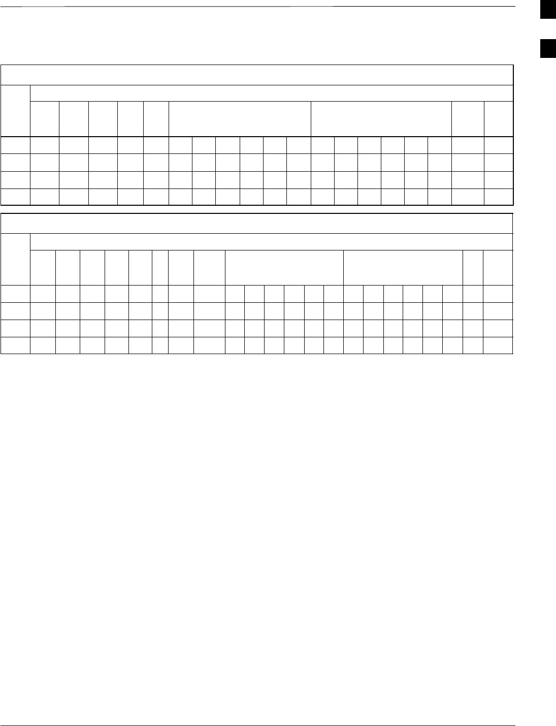
Table 1-3: C–CCP Shelf/Cage Card/Module Device ID Numbers (Top Shelf)
Frame
#
Card/Module ID Number (Left to Right)
#Power
(PS–1)
Power
(PS–2)
Power
(PS–3)
AMR
–1
GLI–
1
MCC BBX BBX–
R
MPC/
EMPC
–1
1 – – – 1 1 1 2 3 4 5 6 1 2 3 4 5 6 R1 –
101 –––101 101 101 102 103 104 105 106 101 102 103 104 105 106 R101 –
201 –––201 201 201 202 203 204 205 206 201 202 203 204 205 206 R201 –
301 –––301 301 301 302 303 304 305 306 301 302 303 304 305 306 R301 –
Table 1-4: C–CCP Shelf/Cage Card/Module Device ID Numbers (Bottom Shelf)
Frame
#
Card/Module ID Number (Left to Right)
#HSO/
LFR
CSM
–1
CSM
–2
CCD
A
CCD
B
AMR
–2
GLI–2 MCC BBX SW MPC/
EMPC
–2
1 – 1 2 – – – 2 2 7 8 9 10 11 12 7 8 9 10 11 12 – –
101 –101 102 – – – 102 102 107 108 109 110 111 112 107 108 109 110 111 112 – –
201 –201 202 – – – 202 202 207 208 209 210 211 212 207 208 209 210 211 212 – –
301 –301 302 – – – 302 302 307 308 309 310 311 312 307 308 309 310 311 312 – –
1
BTS Equipment Identification – continued
1-26 1X SC4812T–MC BTS Optimization/ATP 5/21/04
DRAFT
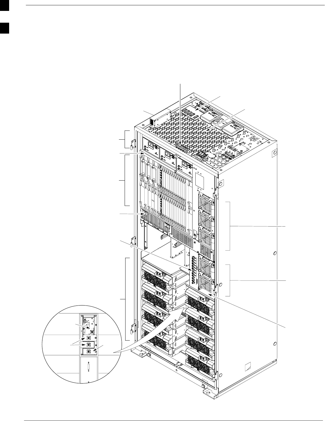
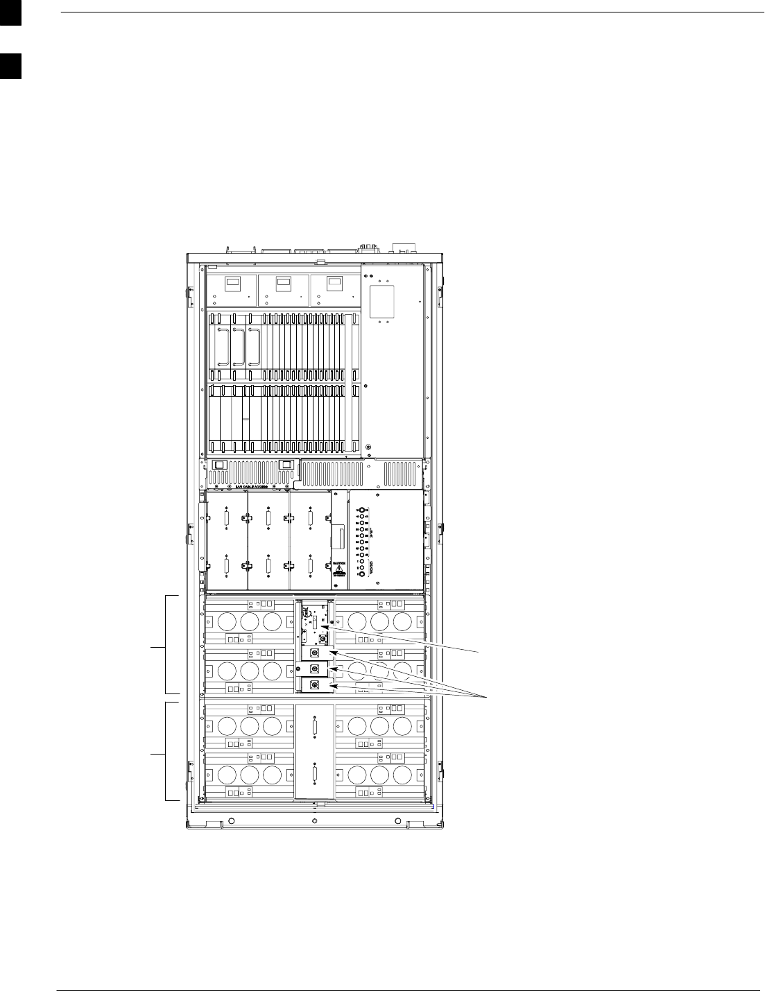
Figure 1-6: BTS Starter Frame (–48V)
Enhanced
Trunking
Module
TX
Filter
TX Filter
or TX
Terminators
Power
Supply
Modules
C–CCP Cage
Fan Module
Power
Alarms
Card
ti-CDMA-WP-00320-v01-ildoc-ftw
C–CCP Cage
PA Cage
and PA Breakers
Air Plenum
Power
Supply
Modules
I/O Interconnect Plate
(See NO TAG)
PHYSICAL APPEARANCE OF FRAMES: The physical
appearance of the frame, especially the location of the
MCM, Power Amplifier cage, and Power
Distribution/Combiner cage, and the particular I/O plate
used, may differ on frames converted from early version
SC4812T BTSs. Functionally however, and for the purpose
of optimization and acceptance testing, those frames are
identical.
For clarity, doors are not shown.
Multi–Carrier Module
(MCM) detail
RGD Module (Installed
when site is expanded)
Cable
Channel Cover
FE Connector
ESM
1
BTS Equipment Identification – continued
5/21/04 1X SC4812T–MC BTS Optimization/ATP 1-27
DRAFT
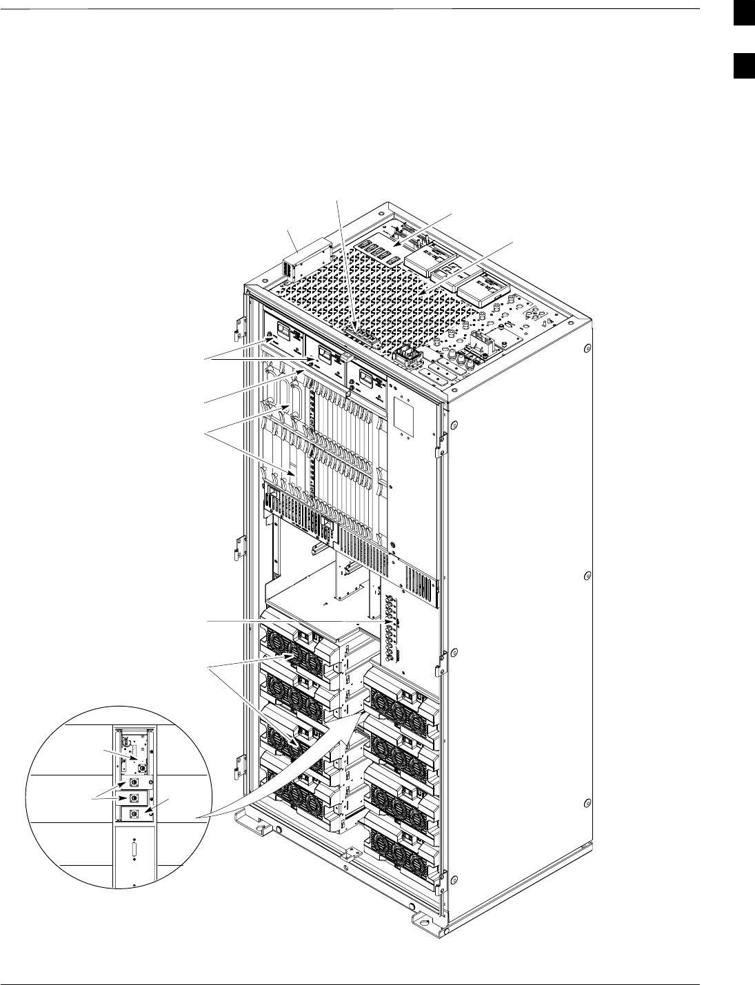
Figure 1-7: BTS Starter Frame (+27V)
For clarity, doors are not shown.
C–CCP Cage
Fan Module
ti-CDMA-WP-00317-v01-ildoc-ftw
C–CCP Cage
PA Cage
and PA Breakers
I/O Interconnect Plate
(See Figure 1-12)
FE Connector
PHYSICAL APPEARANCE OF FRAMES: The physical
appearance of the frame, especially the location of the
MCM, Power Amplifier cage, and Power
Distribution/Combiner cage, and the particular I/O plate
used, may differ on frames converted from early version
SC4812T BTSs. Functionally however, and for the purpose
of optimization and acceptance testing, those frames are
identical.
RGD Module
(Installed when site
is expanded)
Enhanced
Trunking
Module
TX
Filter
Multi–Carrier Module
(MCM) detail
TX Filter
or TX
Terminators
Cable Channel
Cover
ESM
1
BTS Equipment Identification – continued
1-28 1X SC4812T–MC BTS Optimization/ATP 5/21/04
DRAFT
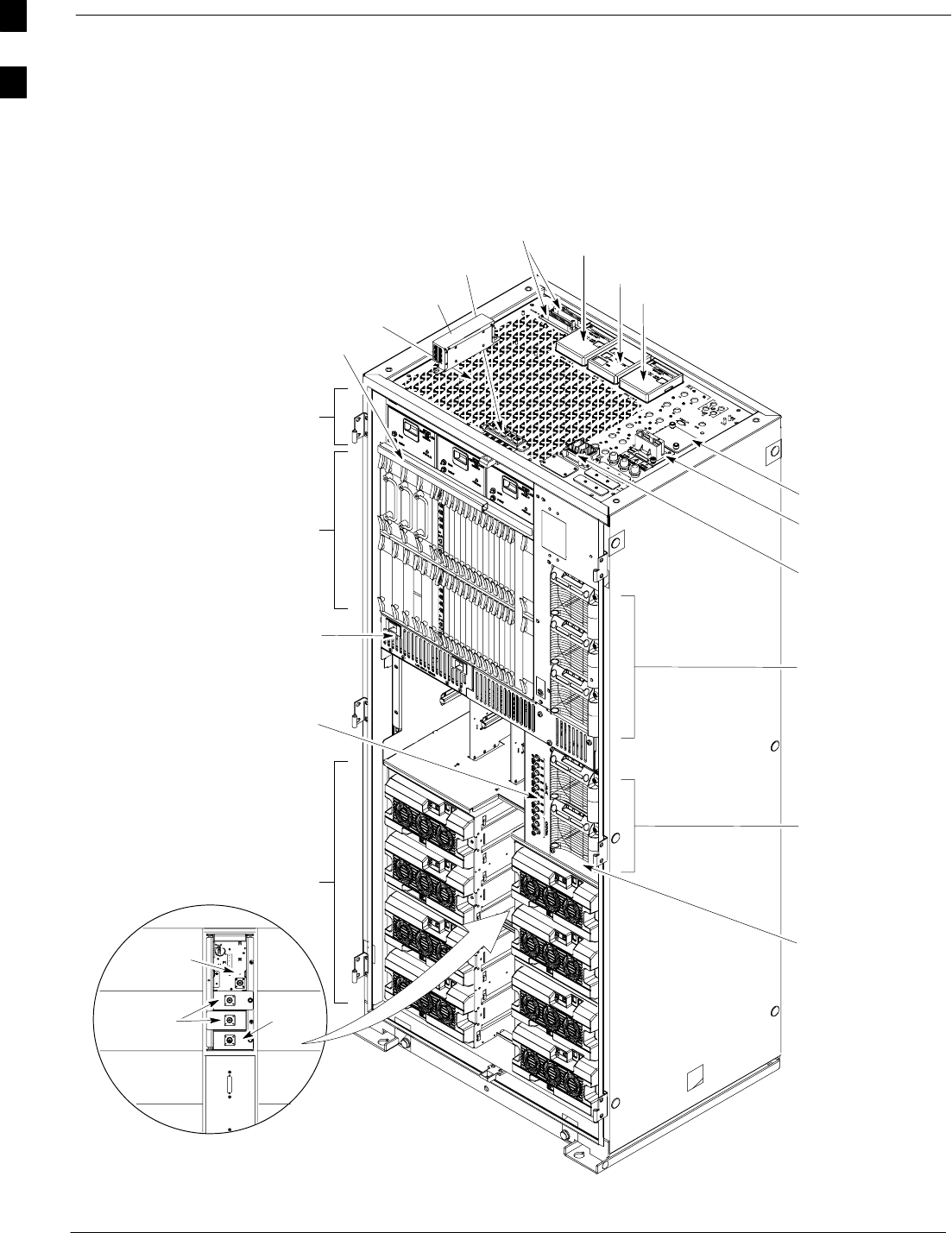
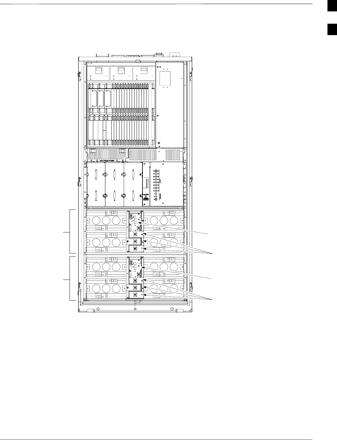
Figure 1-8: BTS Expansion Frame (–48V)
Expansion
I/O Housing
For clarity, doors are not shown.
Input Connector/
DC Filter
Span I/O B
Span I/O A
Site I/O
Exhaust Region
C–CCP Cage
PA Cage
Alarms
Fan Module
Power Alarms
Card
Filler Plate
ti-CDMA-WP-00318-v01-ildoc-ftw
Power Supply
Modules
Power Supply
Modules
Air Plenum
Enhanced
Trunking
Module
TX
Filter
TX Filter
or TX
Terminators
Multi–Carrier Module
(MCM) detail
PHYSICAL APPEARANCE OF FRAMES: The physical
appearance of the frame, especially the location of the
MCM, Power Amplifier cage, and Power
Distribution/Combiner cage, and the particular I/O plate
used, may differ on frames converted from early version
SC4812T BTSs. Functionally however, and for the purpose
of optimization and acceptance testing, those frames are
identical.
C–CCP Cage
and PA Breakers
FE
Connector
Cable Channel
Cover
ESM
1
BTS Equipment Identification – continued
5/21/04 1X SC4812T–MC BTS Optimization/ATP 1-29
DRAFT
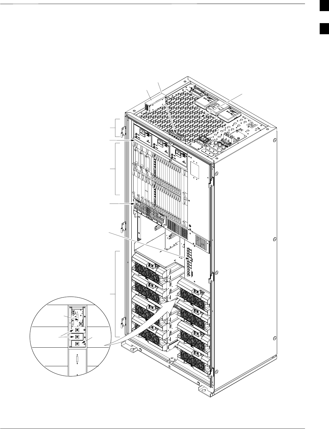
Figure 1-9: BTS Expansion Frame (+27V)
For clarity, doors are not shown.
C–CCP Cage
Fan Module
ti-CDMA-WP-00319-v01-ildoc-ftw
C–CCP Cage
PA Cage
and PA Breakers
Air Plenum
Enhanced
Trunking
Module
TX
Filter
Multi–Carrier Module
(MCM) detail
TX Filter
or TX
Terminators
PHYSICAL APPEARANCE OF FRAMES: The physical
appearance of the frame, especially the location of the
MCM, Power Amplifier cage, and Power
Distribution/Combiner cage, and the particular I/O plate
used, may differ on frames converted from early version
SC4812T BTSs. Functionally however, and for the purpose
of optimization and acceptance testing, those frames are
identical.
FE Connector
Cable Channel
Cover
ESM
1
BTS Equipment Identification – continued
1-30 1X SC4812T–MC BTS Optimization/ATP 5/21/04
DRAFT
Figure 1-10: BTS Multi–Carrier Frame 3 Sector
PA Cage Configuration (+27V)
ti-CDMA-WP-00210-v01-ildoc-ftw REF
Enhanced
Trunking Module
PA Cage
PA Cage
PHYSICAL APPEARANCE OF
FRAMES: The physical appearance of
the frame, especially the location of the
MCM, Power Amplifier cage, and Power
Distribution/Combiner cage, and the
particular I/O plate used, may differ on
frames converted from early version
SC4812T BTSs. Functionally however,
and for the purpose of optimization and
acceptance testing, those frames are
identical.
TX Filters
(one per sector)
NOTE:
The fourth PA quadrant (quadrant D– see Figure 1-15) is
populated with CLPAs only whe the 4x4 ETM is
used.
For an SC4812T BTS frame which has been converted
to multicarrier capability, a fourth three–sector
carrier, using BBX–10 through BBX–12, is supported
in R16.4 and later software releases. In a converted
multicarrier frame, PA slot 4 in all PA quadrants
should never be populated.
1
BTS Equipment Identification – continued
5/21/04 1X SC4812T–MC BTS Optimization/ATP 1-31
DRAFT
Figure 1-11: BTS Multi–Carrier Frame 6–Sector PA Cage Configuration (+27V)
ti-CDMA-WP-00196-v01-ildoc-ftw REF
Enhanced
Trunking Module
Enhanced
Trunking Module
PA Cage
PA Cage
TX Filters
(one per sector)
TX Filters
(one per sector)
NOTE:
The fourth PA quadrant
(quadrant D – (see Figure 1-15)
is populated with CLPAs only
when the 4x4 ETM is used.
BTS Frame Description
The BTS is the interface between the span lines to/from the Centralized
Base Station Controller (CBSC) and the site antennas. This frame is
described in three sections:
SThe top interconnect panel where all connections are made.
SThe upper portion of the frame which contains circuit breakers,
cooling fans, and the C–CCP shelf.
SThe lower portion of the frame which contains the PAs and PA fans,
Parallel Linear amplifier Combiners (PLC), Enhanced Trunking
Module(s) (ETM), and TX filters.
1

BTS Equipment Identification – continued
1-32 1X SC4812T–MC BTS Optimization/ATP 5/21/04
DRAFT
Top Interconnect (I/O) Panel
All cabling to and from the BTS equipment frames is accomplished at
the I/O panel (seeFigure 1-12and Figure 1-13) on top of each frame. The
I/O panel layout is identical for +27V and –48V frames starter and
expansion frames with the exception that the power input label is
voltage–specific and the RX Expansion port location changes as shown
inFigure 1-12and Figure 1-13. Connections at the I/O panel include:
SSpan lines
SRX antennas
STX antenna
SAlarm connections
SPower input
SLAN connections
SRF GPS input or Remote Global Positioning System (RGPS) on the
Site I/O Board
SRGPS Distribution (RGD) card
SExpansion frame connection
SGround connections
SESM
1
BTS Equipment Identification – continued
5/21/04 1X SC4812T–MC BTS Optimization/ATP 1-33
DRAFT
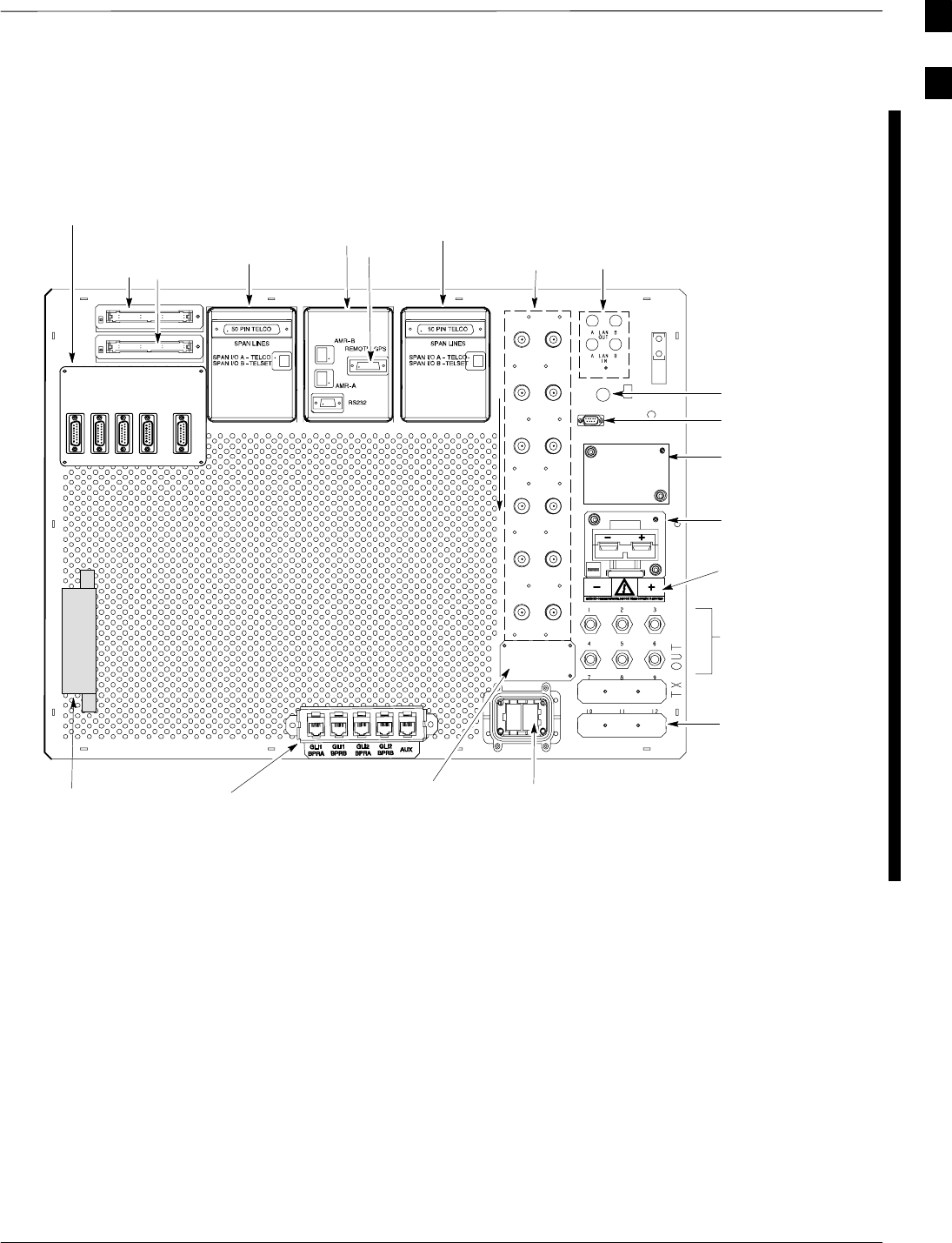
Figure 1-12: Starter Frame I/O Panel
FRONT
SPAN I/O
SITE I/O
ALARM
CONNECTORS
LAN
CONNECTIONS
RF GPS IN
3 TO 6 TRANSMIT
ANTENNA
CONNECTORS
(DEPENDING ON
CONFIGURATION)
HSO/LFR
FILLER PLATE
RECEIVE
ANTENNA
CONNECTORS
INPUT CONNECTOR/
DC FILTER
FAST ETHERNET
INTERFACE HOUSING (IF
USED; OTHERWISE, FILLER
PLATE USED ON ETHERNET
ROUTER OPENING)
EXP IN FILLER
PLATE
3A
2A
1A
6A
5A
4A
3B
2B
1B
6B
5B
4B
REAR
SPAN I/O A SITE I/O SPAN I/O B
ALARM B
SPAN I/O A
SPAN I/O B
ALARM A
SITE I/O
GND
DC FILTER 2
RX
RX
DC FILTER 1
SPAN I/O
RF EXPANSION PORT TO ANOTHER
BTS (USED ONLY IF EXPANSION FRAME
INSTALLED; OTHERWISE, FILLER PLATE
INSTALLED)
ti-CDMA-WP-00188-v02-ildoc-ftw
RGPS
POWER INPUT LABEL
WILL BE VOLTAGE
SPECIFIC
2 TO 3 TRANSMIT
ANTENNA FILLER
PLATES (DEPENDING
ON CONFIGURATION)
REMOTE GPS DISTRIBUTION (RGD) MODULE -
USED ONLY IF EXPANSION FRAME(S) INSTALLED
AND RGPS IS USED.
ESM
1
BTS Equipment Identification – continued
1-34 1X SC4812T–MC BTS Optimization/ATP 5/21/04
DRAFT
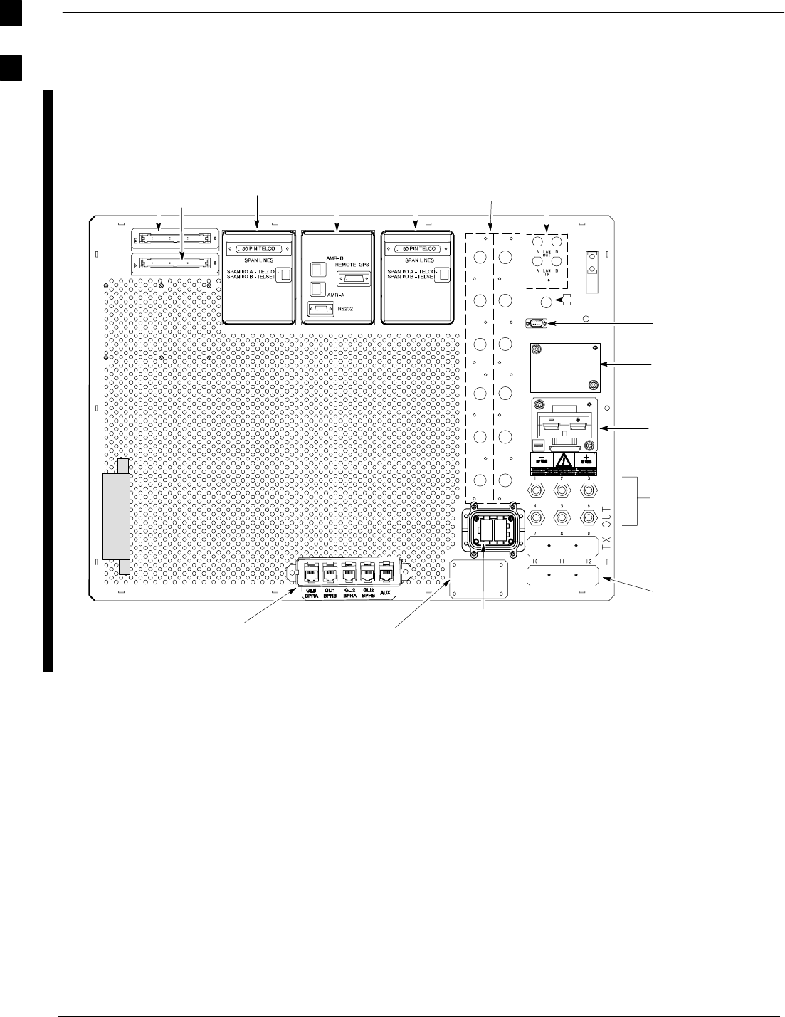
Figure 1-13: Expansion Frame I/O Panel
FRONT
SPAN I/O
SITE I/O
ALARM
CONNECTORS
LAN
CONNECTIONS
GPS IN
HSO/LFR
ti-CDMA-WP-00188-V03-ildoc-ftw
FILLER PLATE
RECEIVE
ANTENNA
COVERS
INPUT
CONNECTOR/
DC FILTER
EXP OUT
FILLER PLATE
3A
2A
1A
6A
5A
4A
3B
2B
1B
6B
5B
4B
REAR
SPAN I/O A SITE I/O SPAN I/O B
ALARM B
SPAN I/O A
SPAN I/O B
ALARM A
SITE I/O
GND
DC FILTER 2
RX
RX
DC FILTER 1
SPAN I/O
RF EXPANSION PORT
FROM STARTER BTS
3 to 6 TX ANTENNA
CONNECTORS
(depending on
configuration)
2 to 3 TX ANTENNA
FILLER PLATES
(depending on
configuration)
FAST ETHERNET INTERFACE HOUSING
(IF USED; OTHERWISE, FILLER PLATE
USED ON ETHERNET ROUTER OPENING)
1
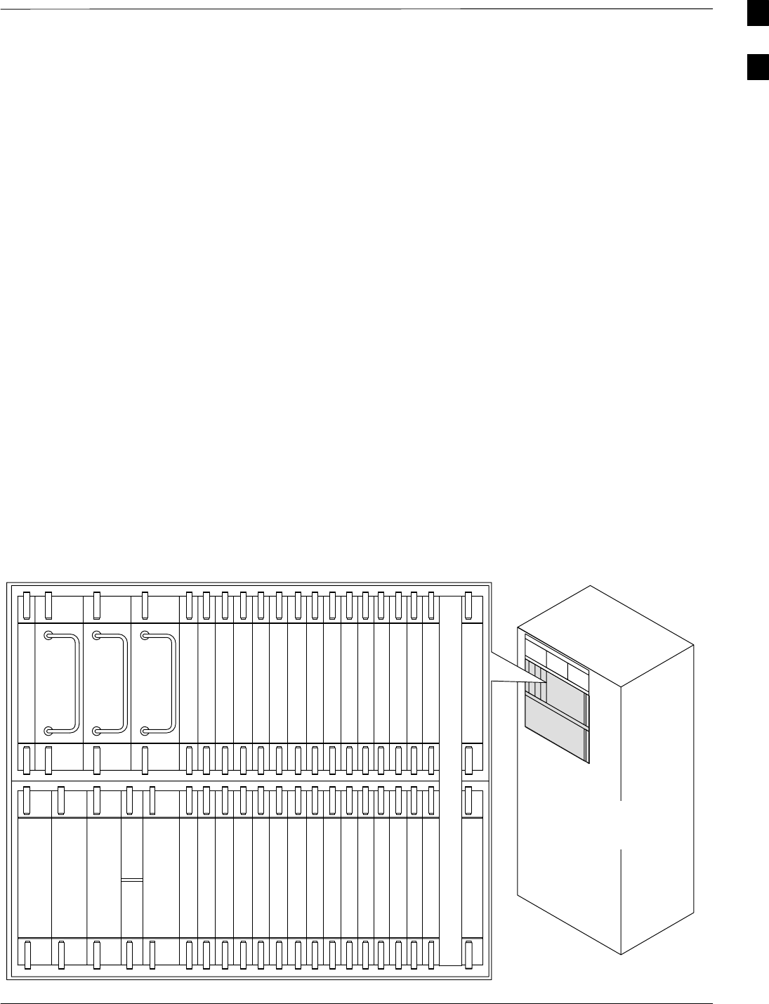
BTS Equipment Identification – continued
5/21/04 1X SC4812T–MC BTS Optimization/ATP 1-35
DRAFT
C–CCP Shelf
The upper portion of the frame houses circuit breakers, cooling fans, and
the Combined–CDMA Channel Processor (C–CCP) shelf (see
Figure 1-14). The C–CCP shelf includes:
SC–CCP backplane and cage
SC–CCP power supplies
SCDMA Clock Distribution (CCD) cards
SCSM and HSO/LFR cards
SAlarm Monitoring and Reporting (AMR) cards
SGLI cards
SMultcoupler Preselector Card (MPC) (starter frame)/Expansion MPC
(EMPC) (expansion frame) cards
SSwitch card
SMCC cards
SBBX cards
SMCIO cards
Figure 1-14: C–CCP Shelf
19 mm Filler Panel
PS–3
AMR–1
CSM–1
CSM–2
38 mm Filler Panel
AMR–2
GLI–1GLI–2
MCC–6
BBX–1
BBX–2
BBX–3
BBX–4
BBX–5
BBX–6
BBX–RSwitch
MPC/EMPC–1MPC/EMPC–2
MCIO
BBX–7
BBX–8
BBX–9
BBX–10
BBX–11
BBX–12
MCC–5
MCC–4
MCC–3
MCC–2
MCC–1
MCC–12
MCC–11
MCC–10
MCC–9
MCC–8
MCC–7
PS–2
PS–1
CCD–2 CCD–1
NOTE: MCCs may be
MCC24Es, MCC8Es, or
MCC–1Xs. GLIs may be
GLI2s or GLI3s.
HSO/LFR
ti-CDMA-WP-00037-v01-ildoc-ftw REF
1
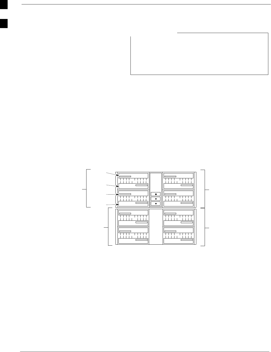
BTS Equipment Identification – continued
1-36 1X SC4812T–MC BTS Optimization/ATP 5/21/04
DRAFT
For an SC4812T BTS frame which has been converted to
multicarrier capability, a fourth three–sector carrier, using
BBX–10 through BBX–12, is supported in R16.4 and later
software releases. In a converted multicarrier frame, PA
slot 4 in all PA quadrants should never be populated.
NOTE
PA Shelves
The lower shelves house the PA cages which include:
SPA modules, PA fans, and Parallel Linear amplifier Combiners (PLCs)
SMulti–Carrier Module (MCM) which includes the Enhanced Trunking
Modules (ETMs), and TX filters
Location Nomenclature
Figure 1-15 presents standardized nomenclature for locations within the
PA cages.
Figure 1-15: PA Cage Location Nomenclature (Original Equipment Manufacture
(OEM) SC4812T–MC 3–Sector Shown)
MCM
1
S1
S2
S3
CLPA
CLPA
CLPA
CLPA
CLPA
CLPA
CLPA
CLPA
CLPA
CLPA
CLPACLPA
1C
2C
3C
4C
1D
2D
3D
4D
3A
2A
1A 1B
2B
3B
4B 4A
CLPA
CLPA
CLPA
CLPA
PA Slot 1
PA Slot 2
PA Slot 3
PA Slot 4
Quadrant A
Quadrant C
Quadrant B
Quadrant D
PAs and Carriers
With changes in the network software for R16.4.1, PA allocation to
carriers in the SC4812T–MC changes significantly. The quantity of PAs
required is no longer dependant on the number of carriers equipped in
the frame. Implementation of the change differs between six sector BTSs
and BTSs equipped for omni, two–sector, and three–sector operation.
Additional details for each BTS sector configuration are provided in the
following paragraphs and Figure 1-20, Figure 1-21, and Figure 1-22.
Omni, two–sector, and three–sector multicarrier BTS – Up to four
carriers can be supported on an omni, two–, or three–sector BTS with
one PA set. If additional power output is required, additional PA sets can
be added up to the maximum of four sets. PAs must be added as
complete sets; that is, three PA modules for a 3x3 system and four PA
modules for a 4x4 system. (Refer to Figure 1-20 and Figure 1-21)
1

BTS Equipment Identification – continued
5/21/04 1X SC4812T–MC BTS Optimization/ATP 1-37
DRAFT
Six–sector BTS – Six–sector operation is only supported in OEM
multicarrier frames. For a six–sector BTS, up to two carriers can be
supported with a minmum of two PA sets: six PA modules for a 3x3
system and eight PA modules for a 4x4 system. If additional power is
required, two additional PA sets can be added for the maximum available
capacity. (Refer to Figure 1-22).
Equipment Configurations
The various components of the PA cages may be configured differently
depending upon customer requirements. Table 1-5 provides BTS
carrier/sector/BBX mapping, TX Filter requirements, and PA quantities
and configurations needed to provide the required BTS output power for
all carriers. Figure 1-16 illustrates which BBXs are used for omni and
two–sector operation. Figure 1-20, Figure 1-21, and Figure 1-22
illustrate the minimum and maximum power PA configurations for
omni, two–, and three–sector OEM and converted multicarrier frames
and for six–sector OEM multicarrier frames, respectively.
Table 1-5: BTS Carrier/Sector/BBX Mapping and ETM/PA Quantities and Power Configurations
Sec
BBXs
Assigned
ETM
TX
3x3 ETM
(Standard Power)
4x4 ETM
(High Power)
S
ec
–
tors
Car–
riers
A
ss
i
gne
d
to
Carrier
ETM
(MCM)
Qty
TX
Filter
Qty
PA Qty Required PLC
Qty
PA Qty Required PLC
Qty
1 1,2,3
Minimum power configuration:
1 PA set in slot 1 of quadrants A
through C (total of 3 CLPAs).
Minimum power configuration:
1 PA set in slot 1 of quadrants A
through D (total of 4 CLPAs).
3
2 7,8,9
1
3
g( )
Additionally required power:
achieved by adding additional PA
sets to a maximum of:
3
g( )
Additionally required power:
achieved by adding additional PA
sets to a maximum of:
4
3
3 4,5,6
1 3
sets to a maximum of:
– OEM multicarrier frames:
4 sets in quadrants A through
C (total of 12 CLPAs)
3
sets to a maximum of:
– OEM multicarrier frames:
4 sets in quadrants A through
D (total of 16 CLPAs)
4
4 10,11,12
()
–Converted multicarrier frames:
3 sets in quadrants A through
C (total of 9 CLPAs)
()
–Converted multicarrier frames:
3 sets in quadrants A through
D (total of 12 CLPAs)
NOTE
Six–sector operation is not available in converted multicarrier frames.
6
11,2,3,
4,5,6
2
6
Minimum power configuration:
two PA sets, one in slot 1 and one in
slot 3 of quadrants A through C
(total of 6 CLPAs) (OEM
multicarrier frames only).
3
Minimum power configuration:
two PA sets, one in slot 1 and one in
slot 3 of quadrants A through D
(total of 8 CLPAs) (OEM
multicarrier frames only).
4
6
27,8,9,
10,11,12
2 6 Additionally required power:
achieved by adding two additional
PA sets, one in slot 2 and one in slot
4 of quadrants A through C (total of
12 CLPAs) (OEM multicarrier
frames only).
3Additionally required power:
achieved by adding two additional
PA sets, one in slot 2 and one in slot
4 of quadrants A through D (total of
16 CLPAs) (OEM multicarrier
frames only).
4
1