Nokia Solutions and Networks T6EK1 1X-EVDO SC480 BTS Microcell Base Station Transmtr User Manual print instructions

Nokia Solutions and Networks 1X-EVDO SC480 BTS Microcell Base Station Transmtr print instructions

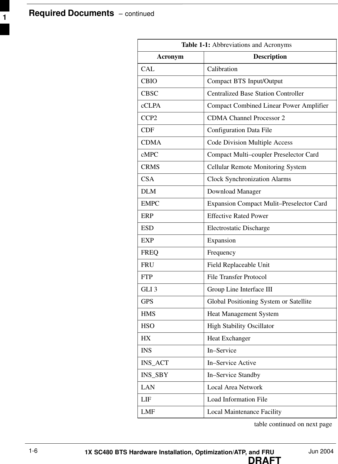
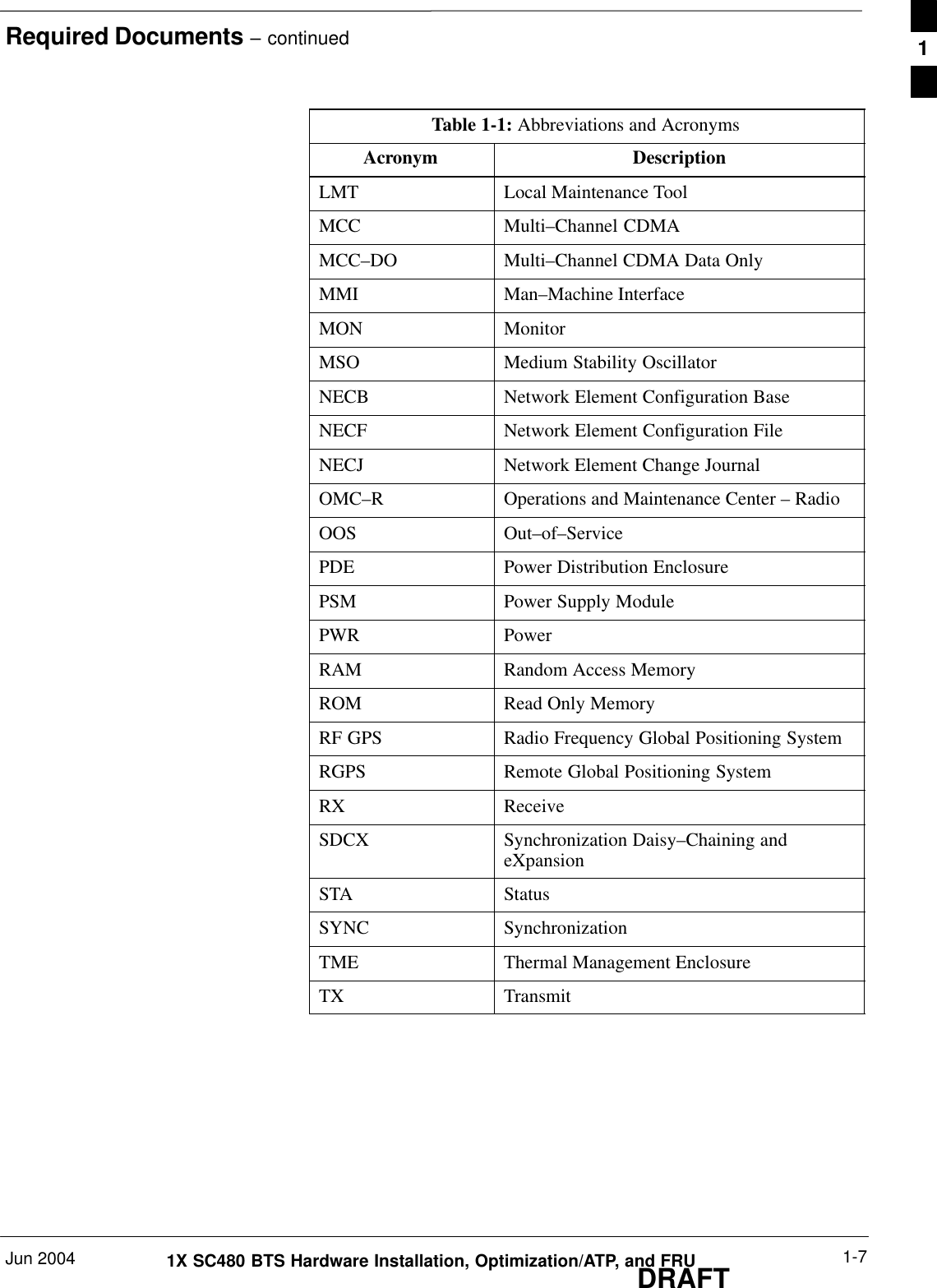
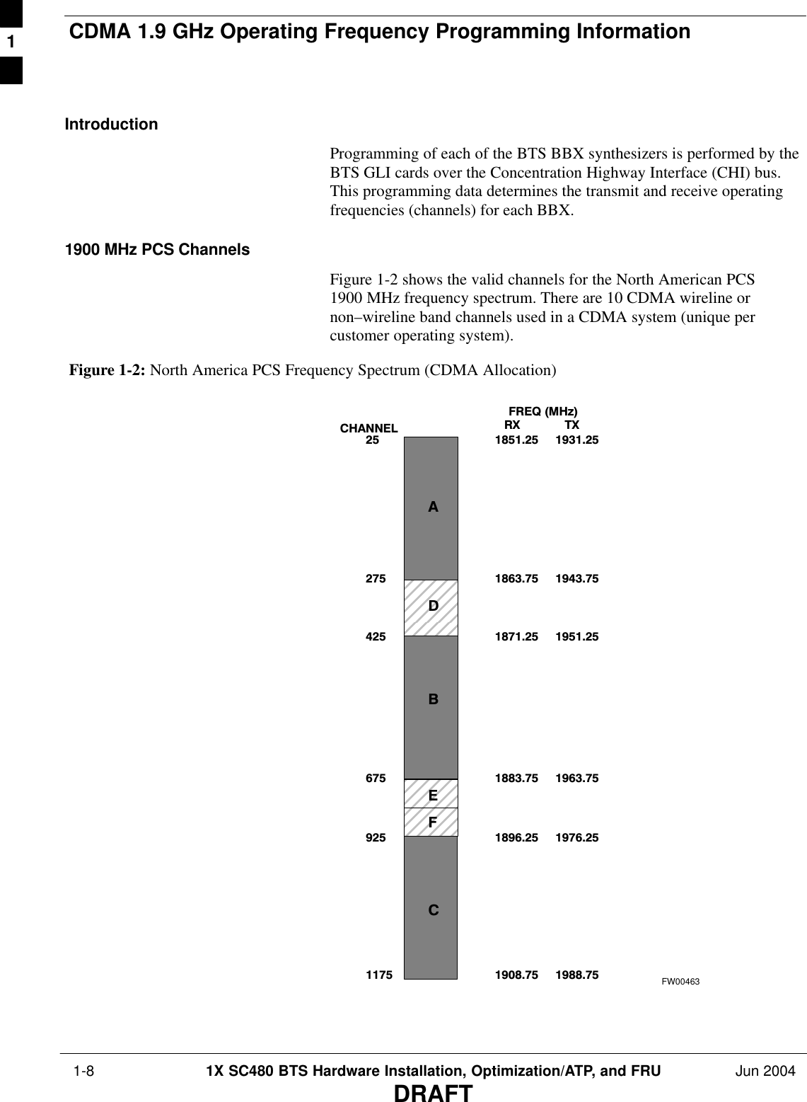
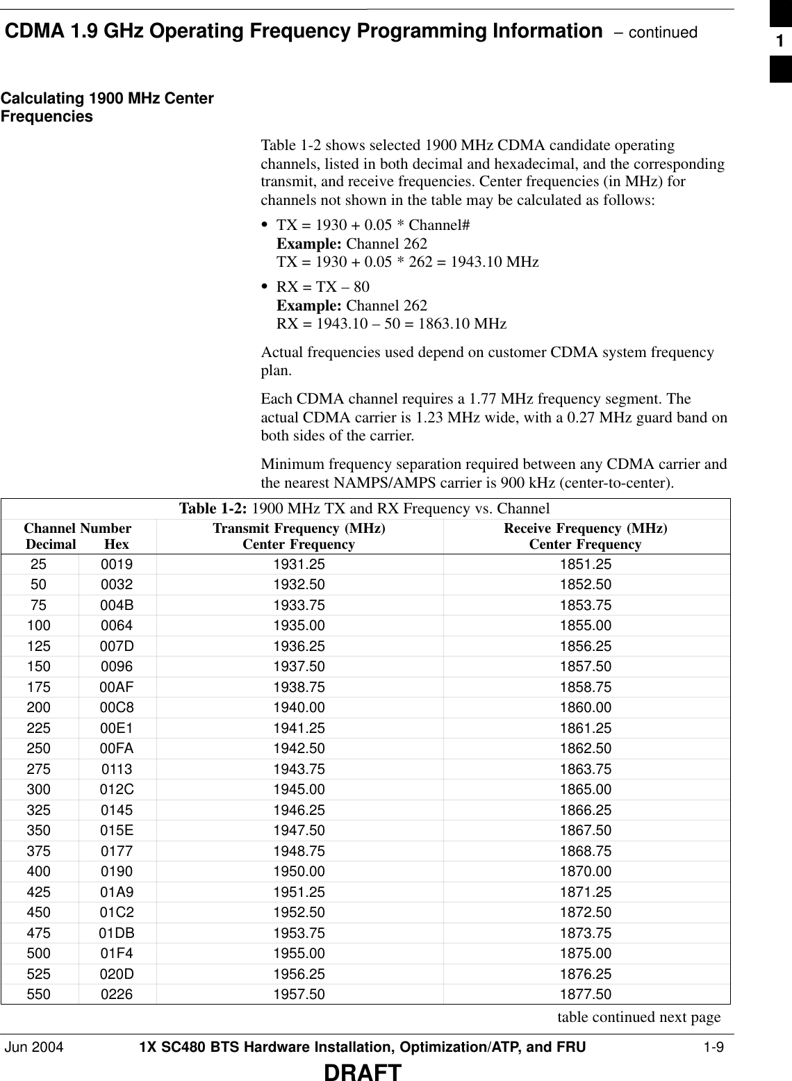
User Manual Part 1 of 4
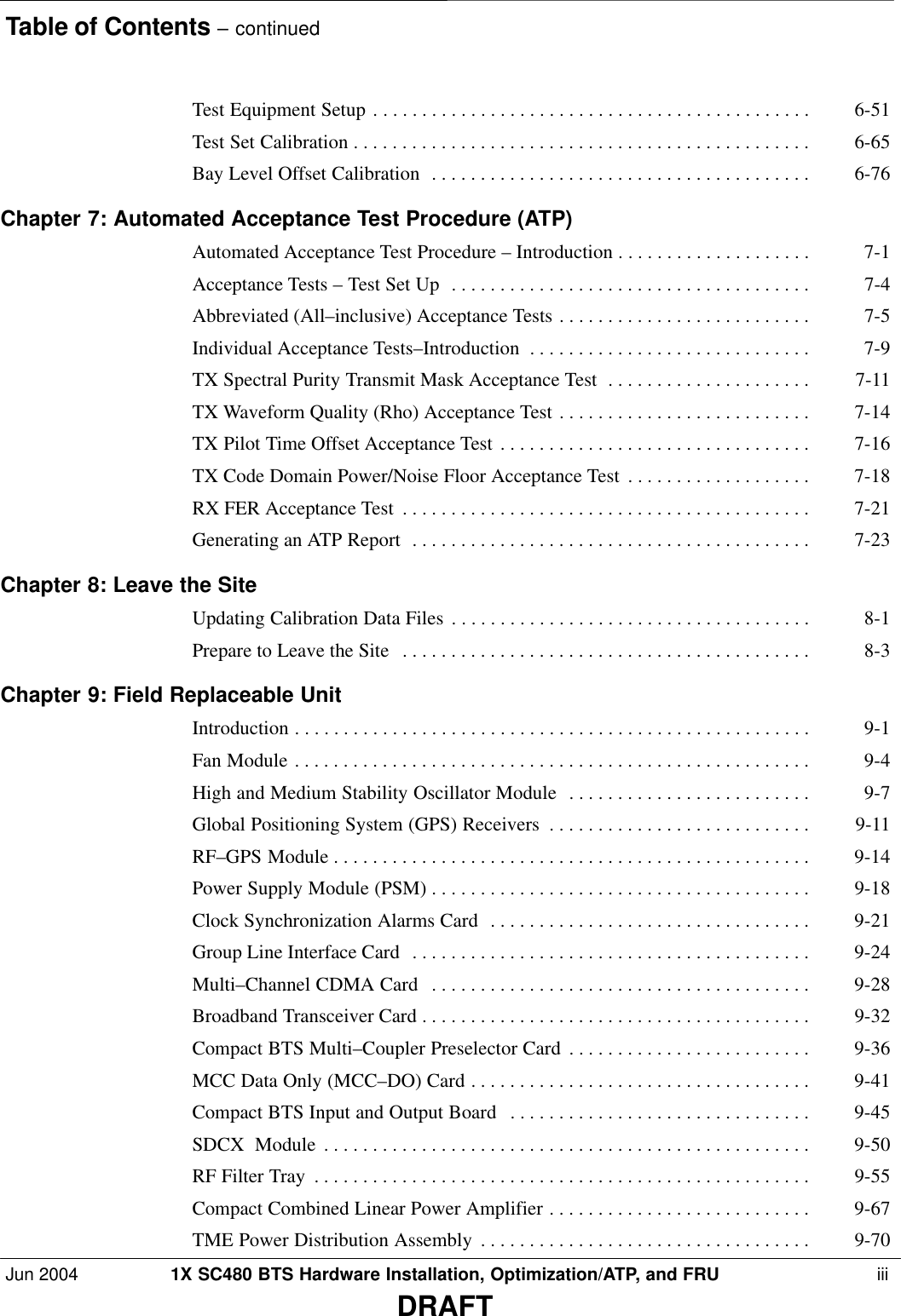
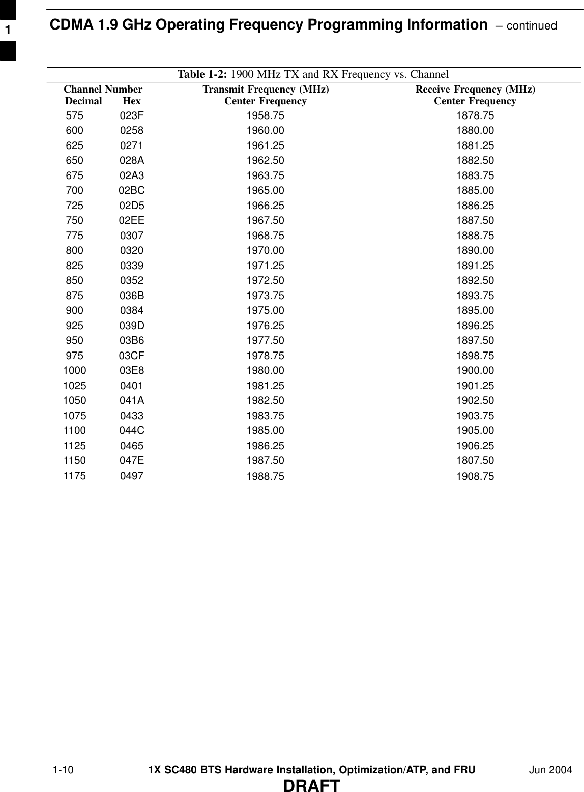
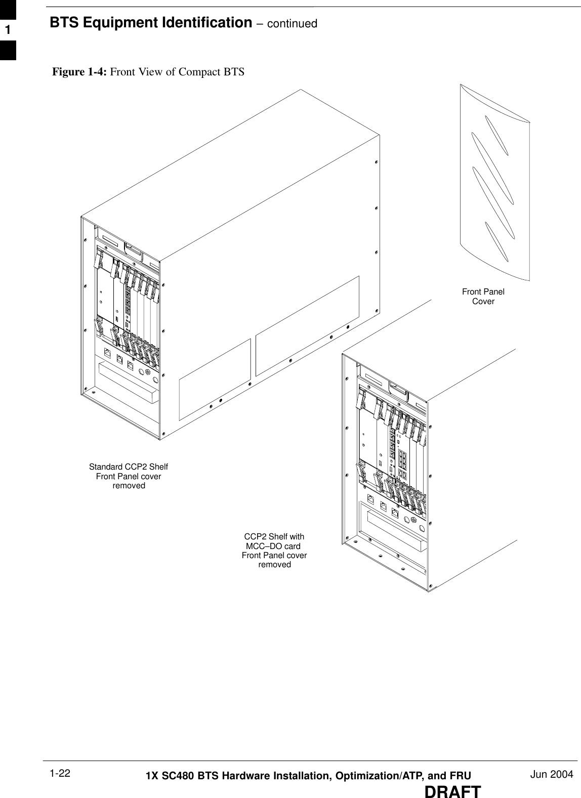
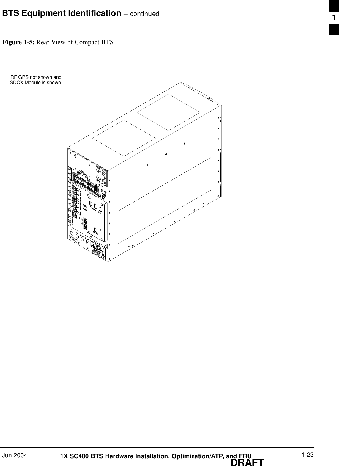
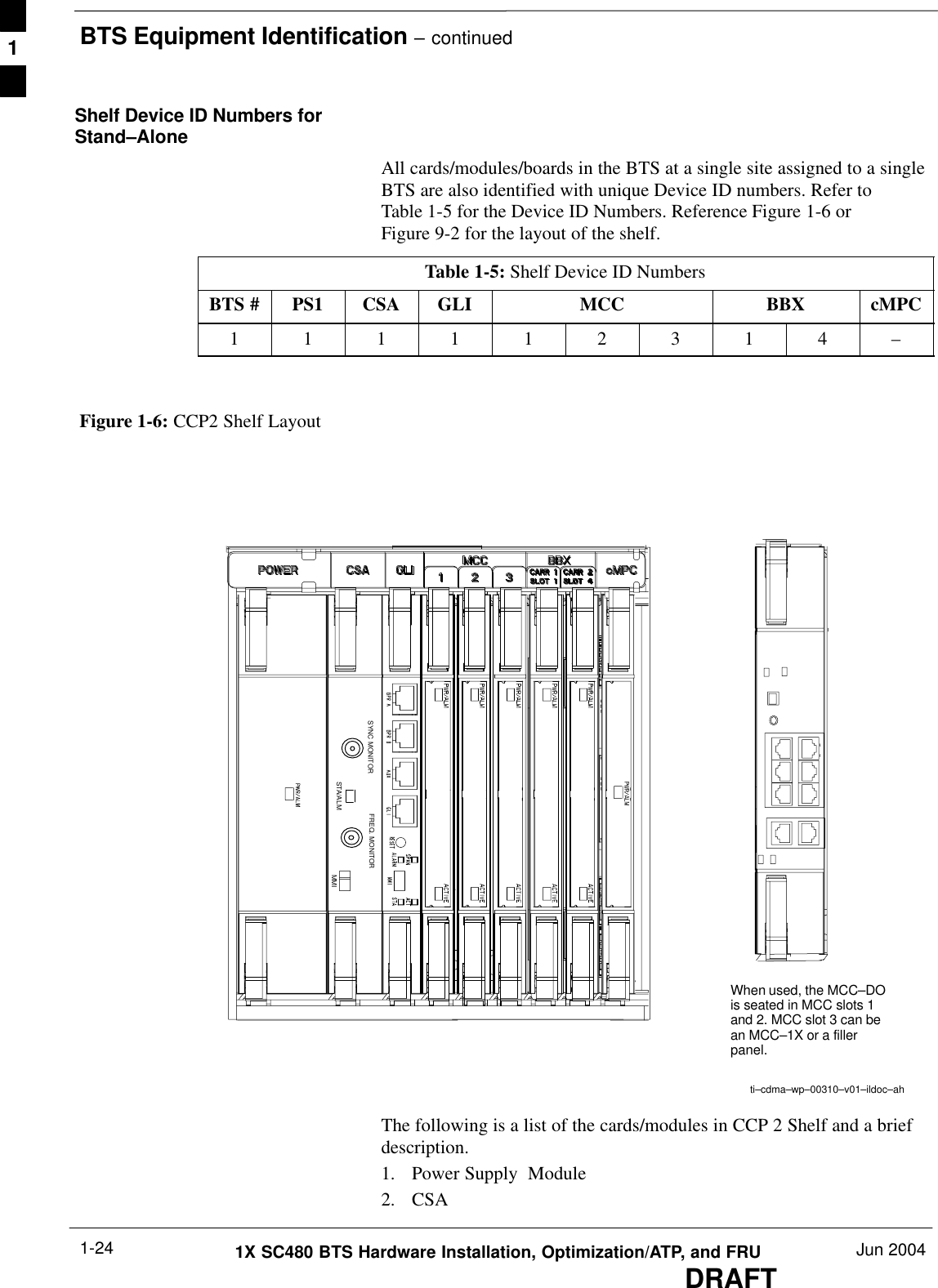
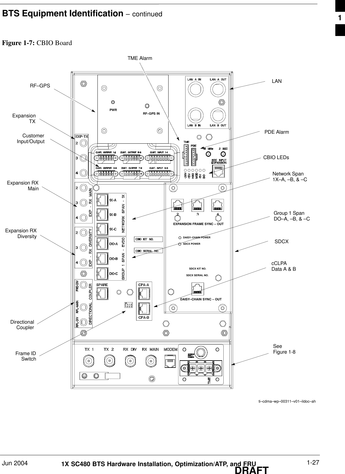
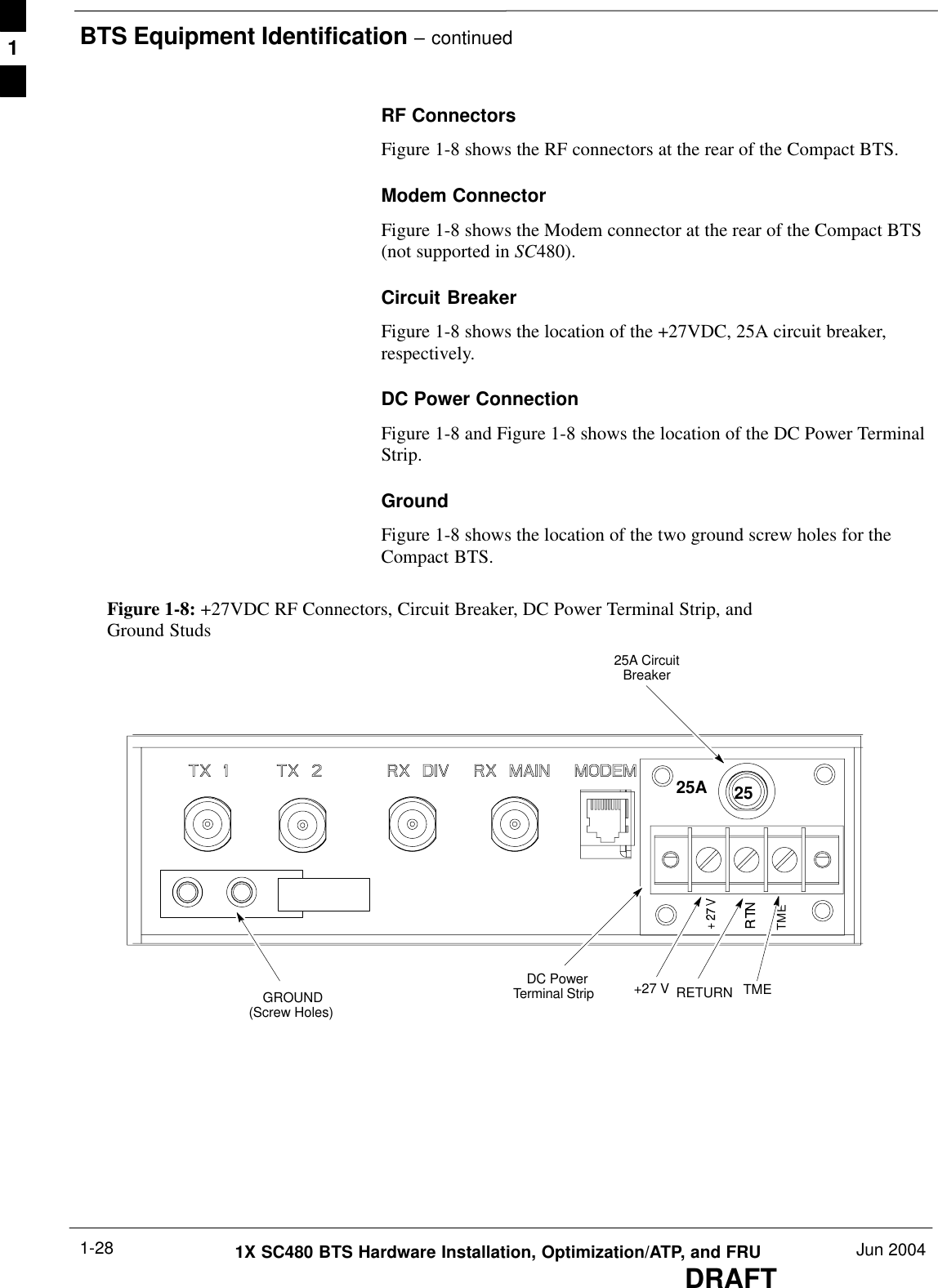
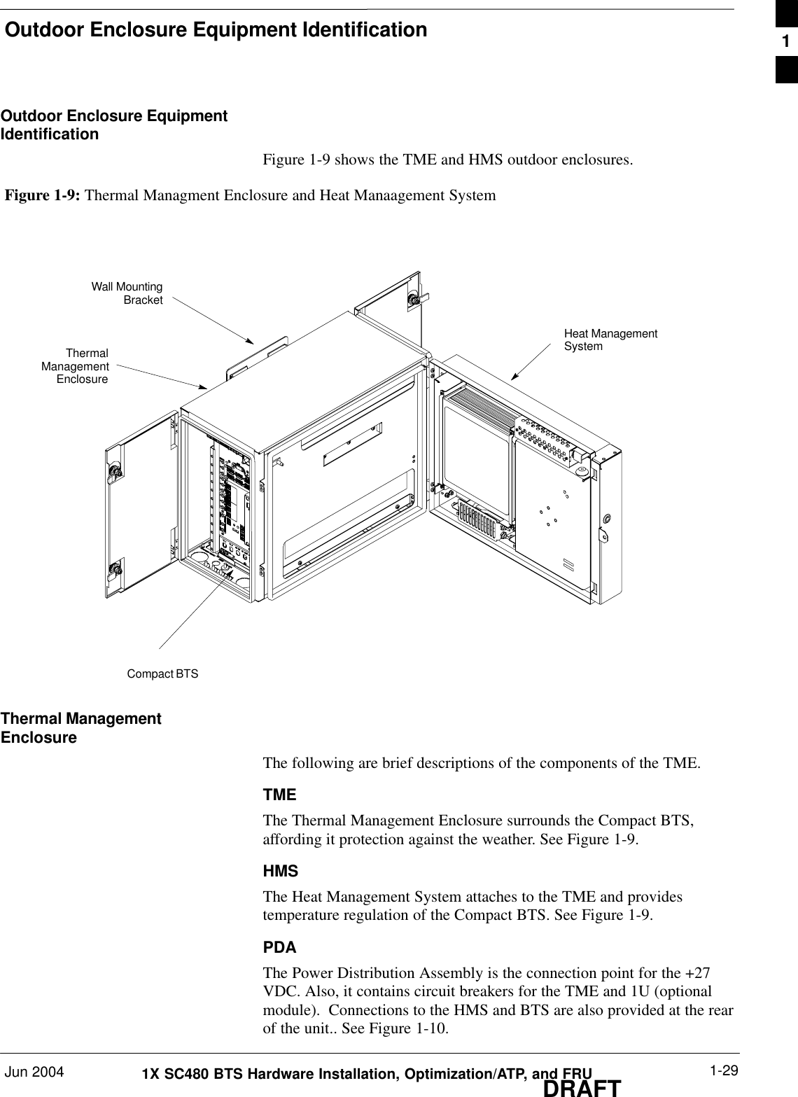
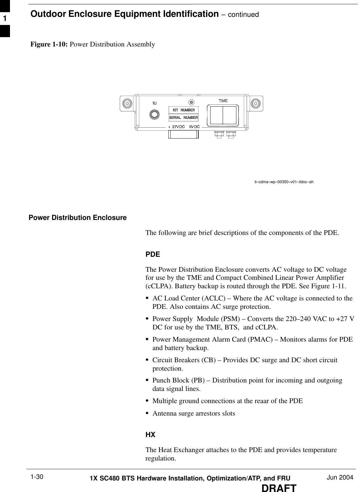
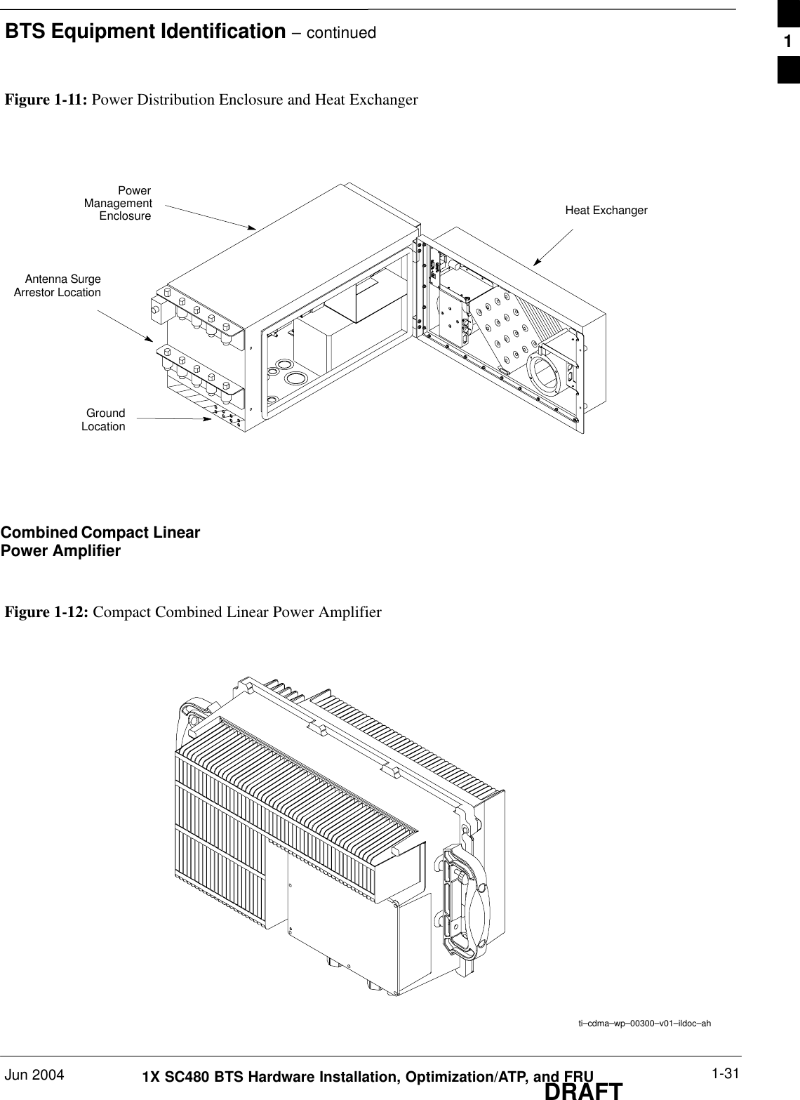
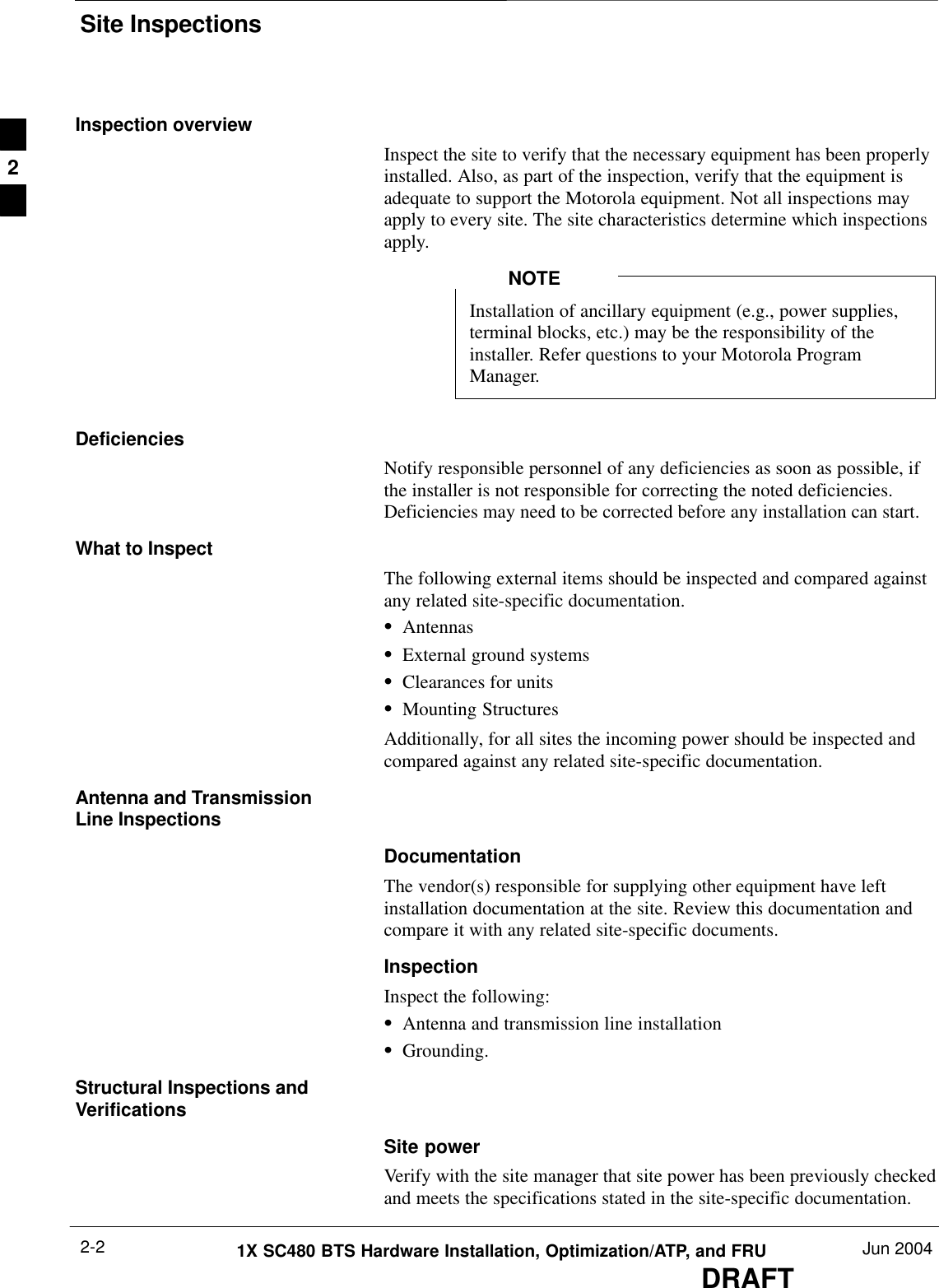
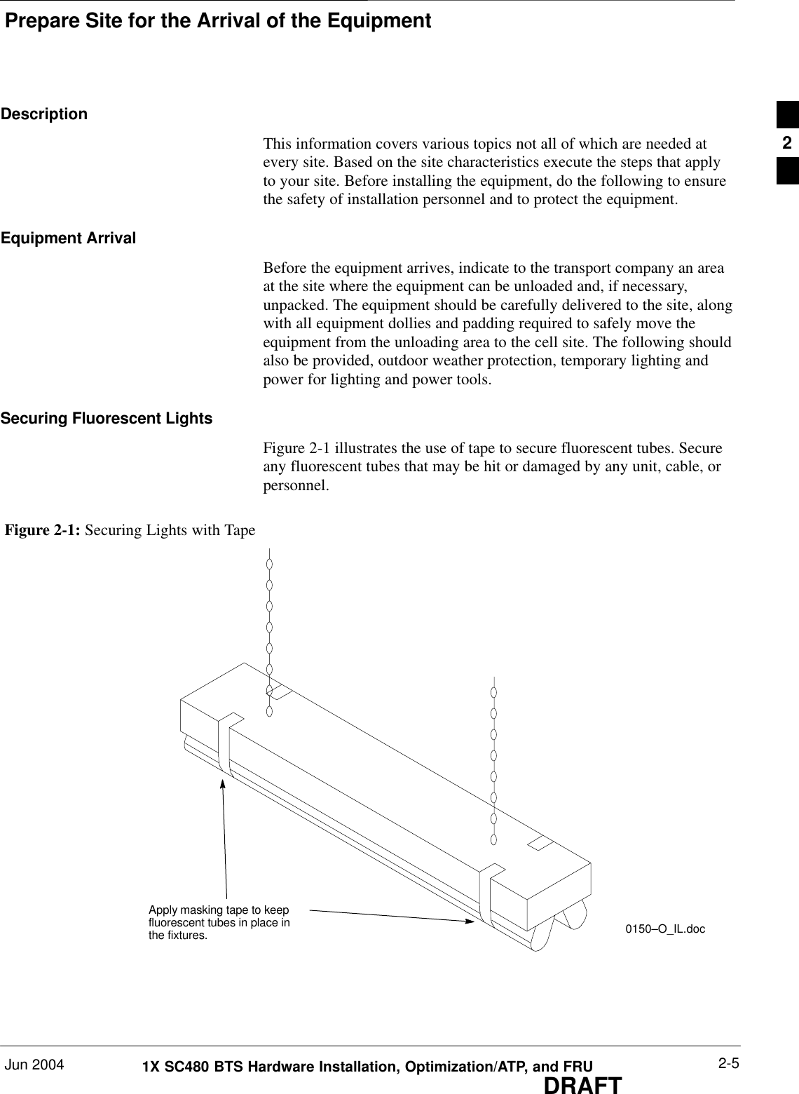
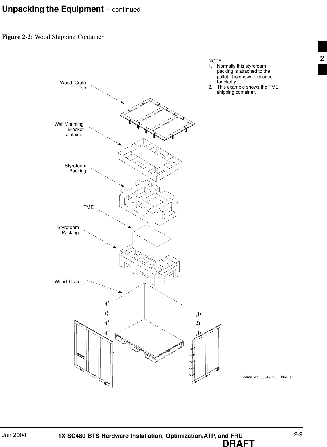
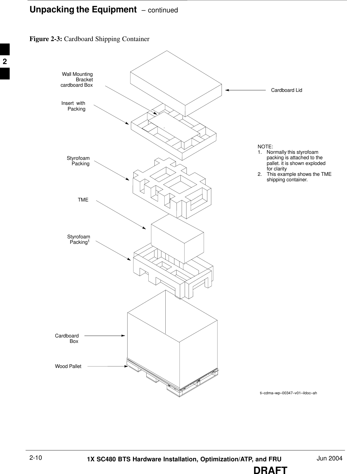
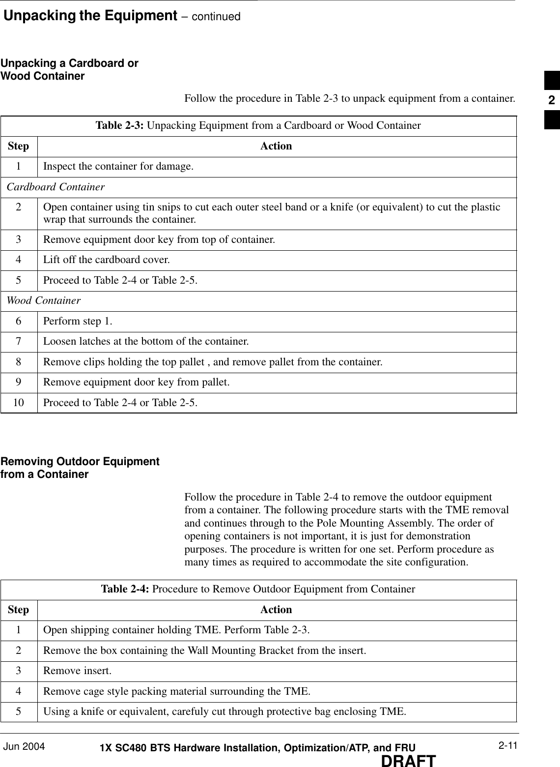
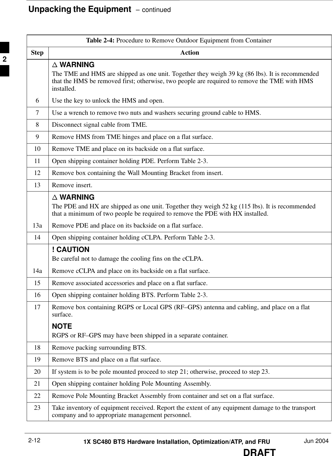
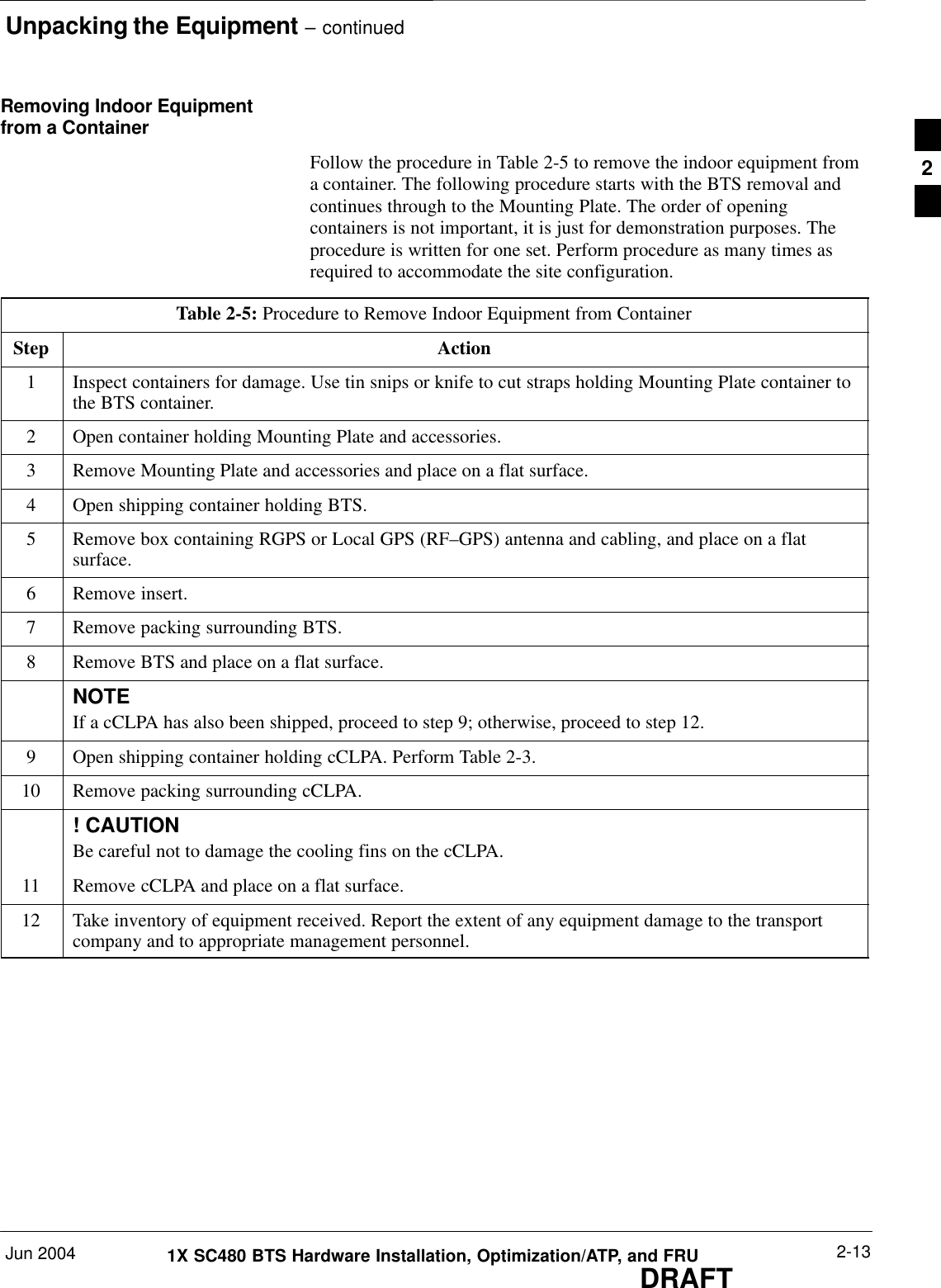
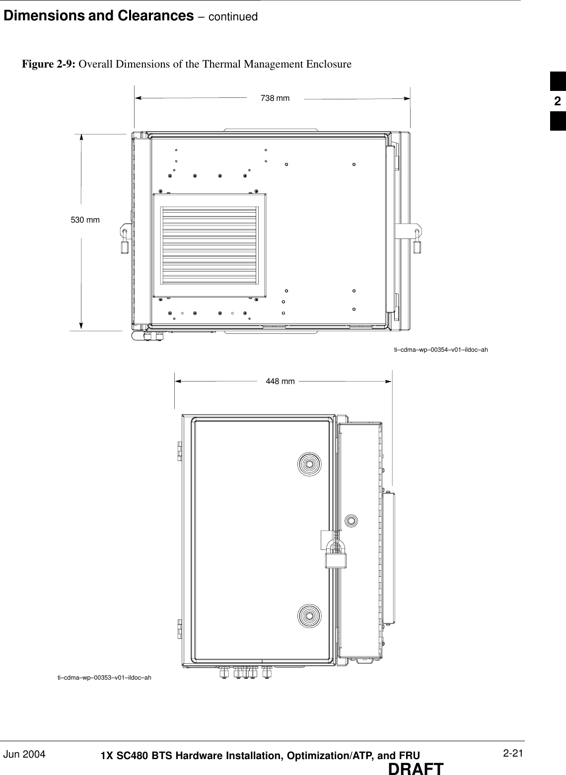
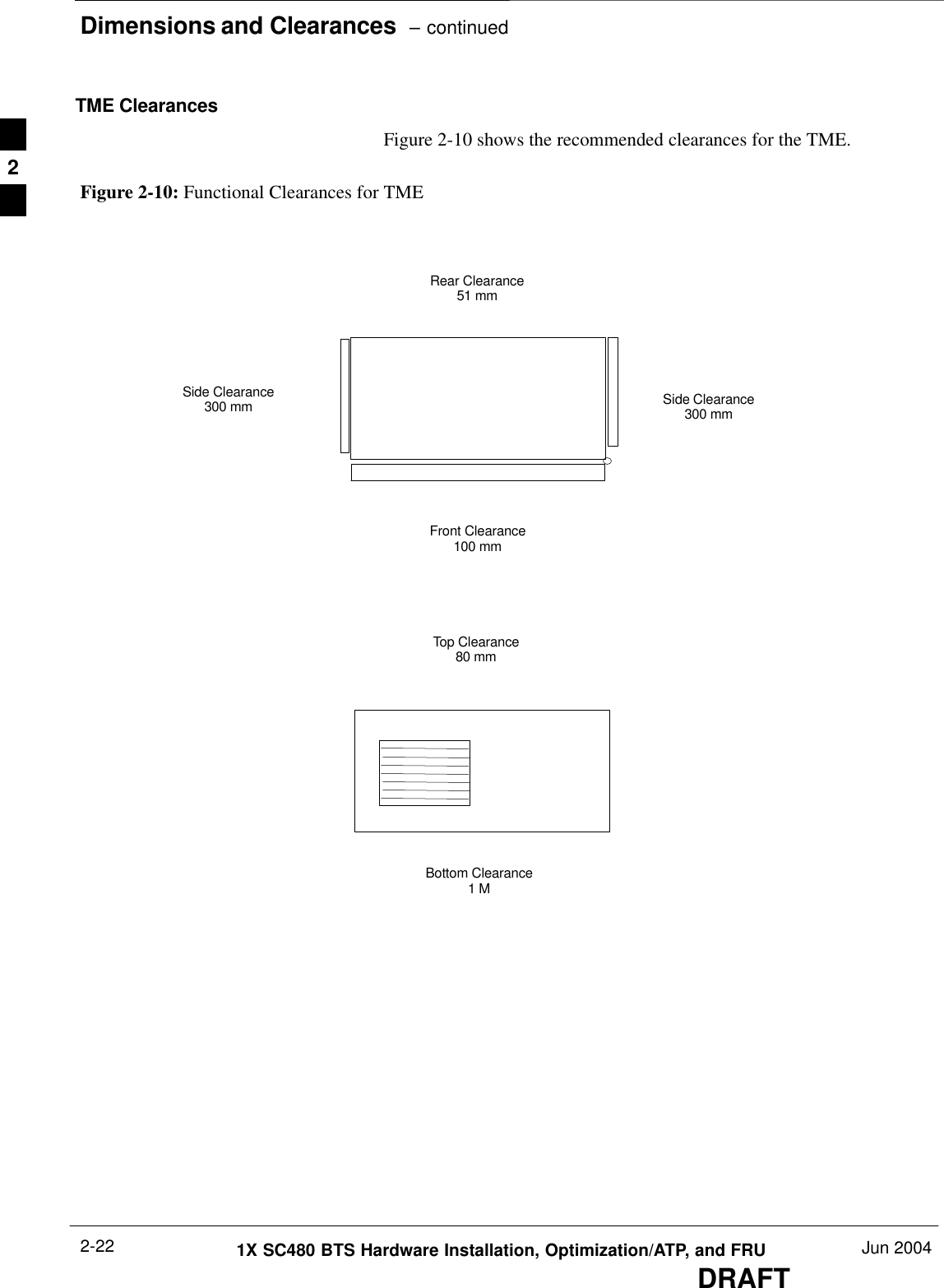
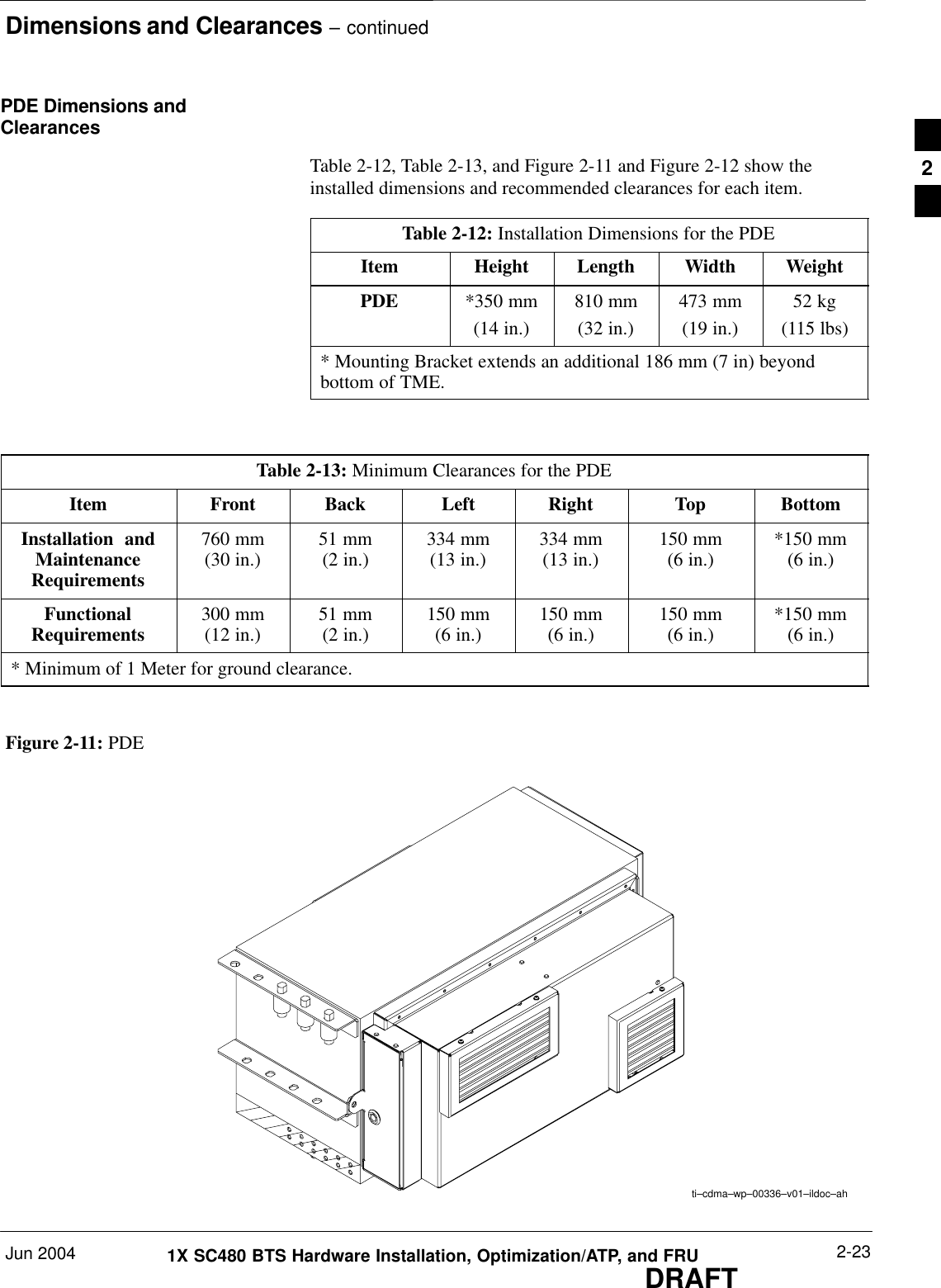
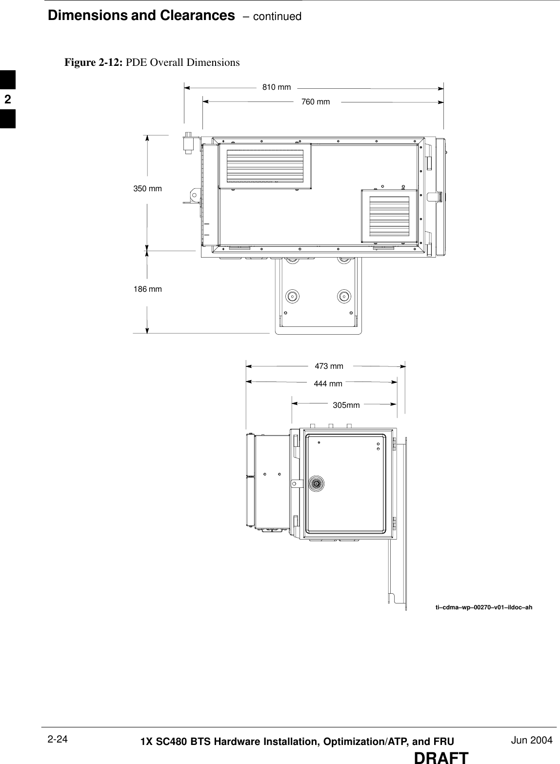
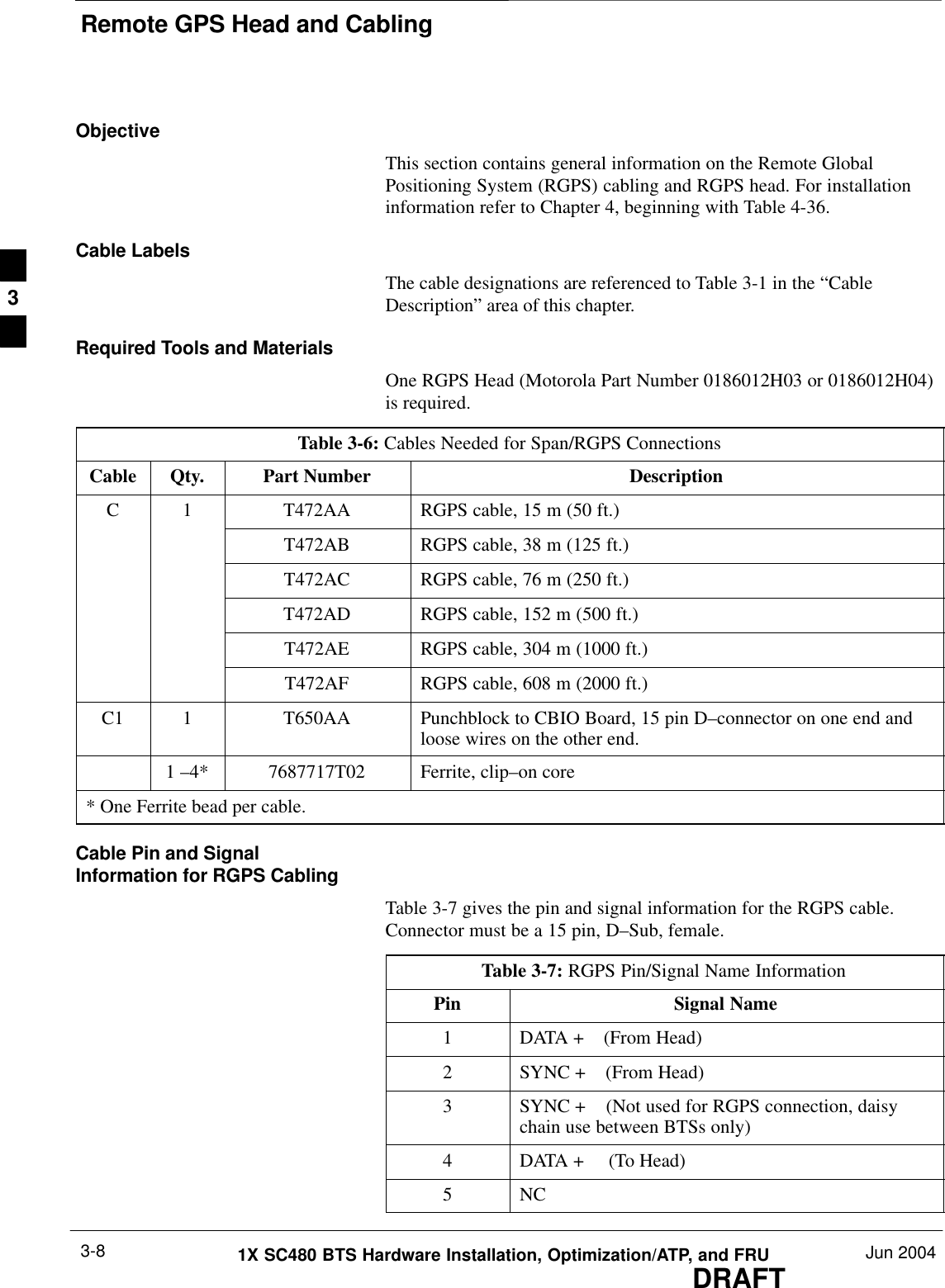
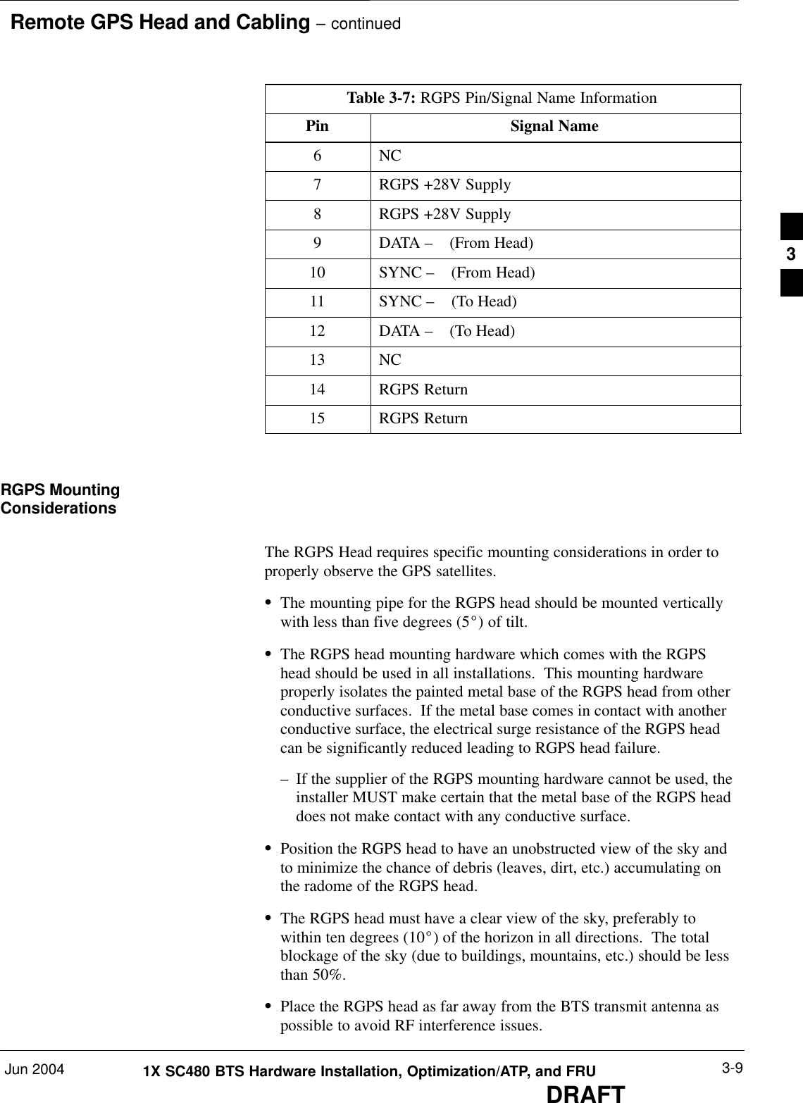
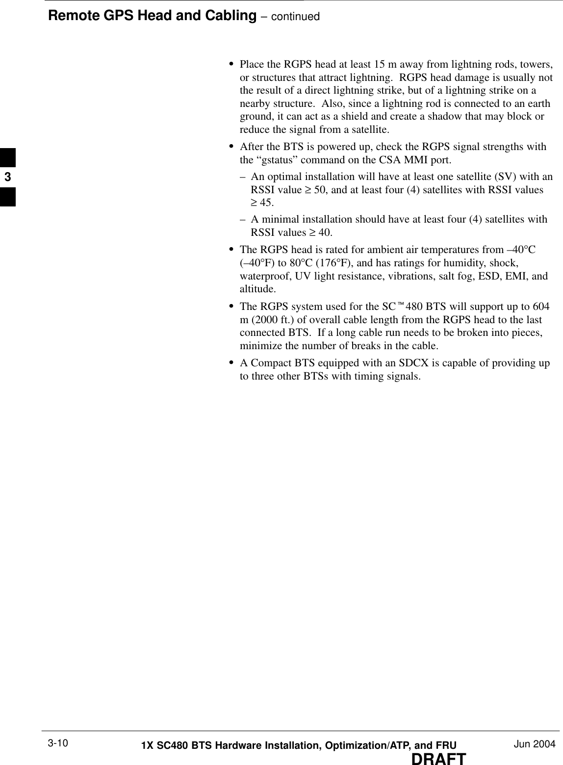
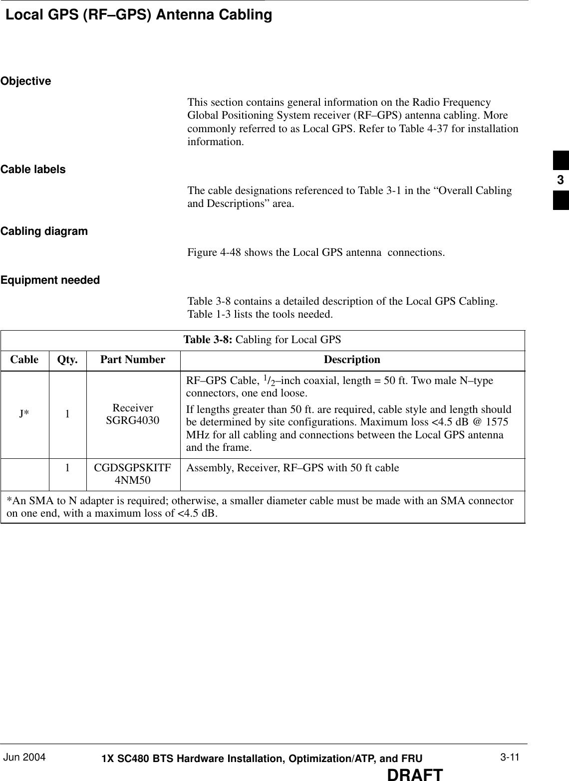
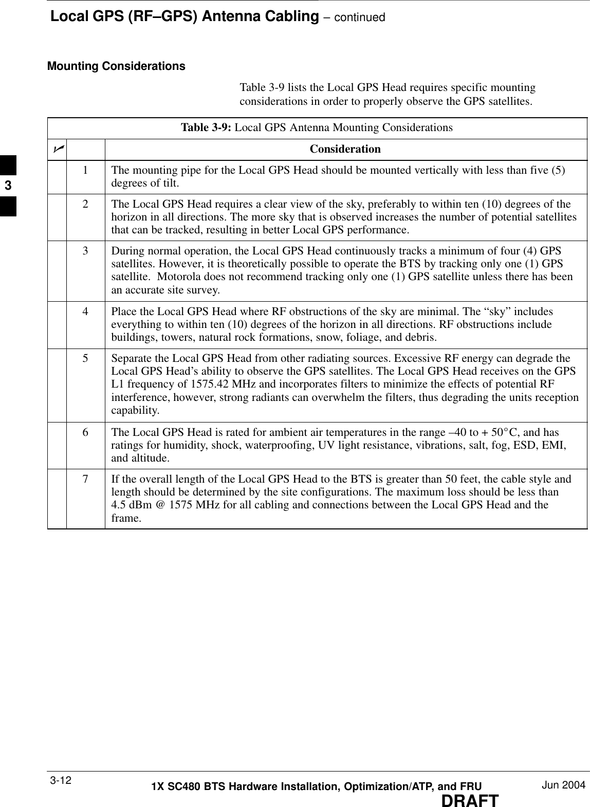
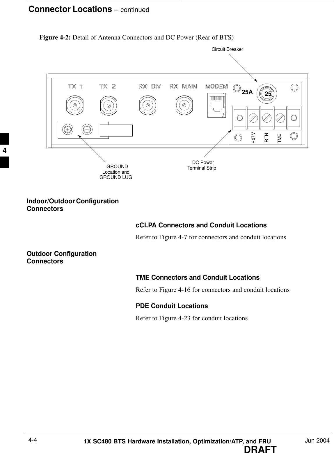
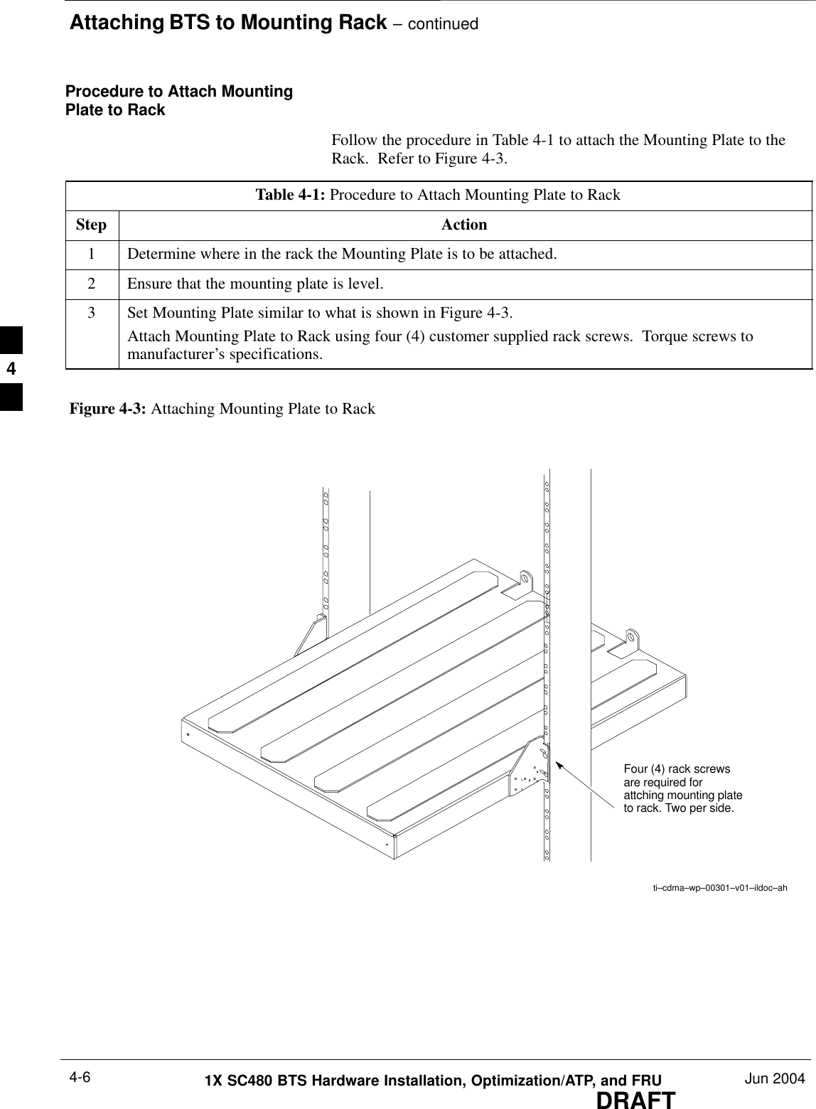
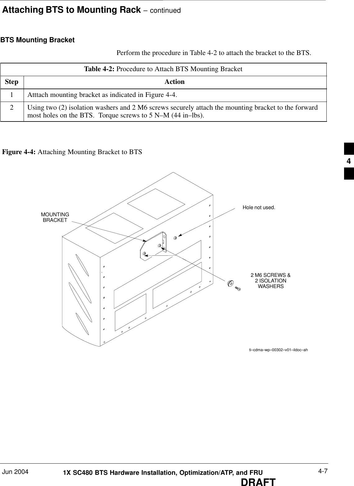
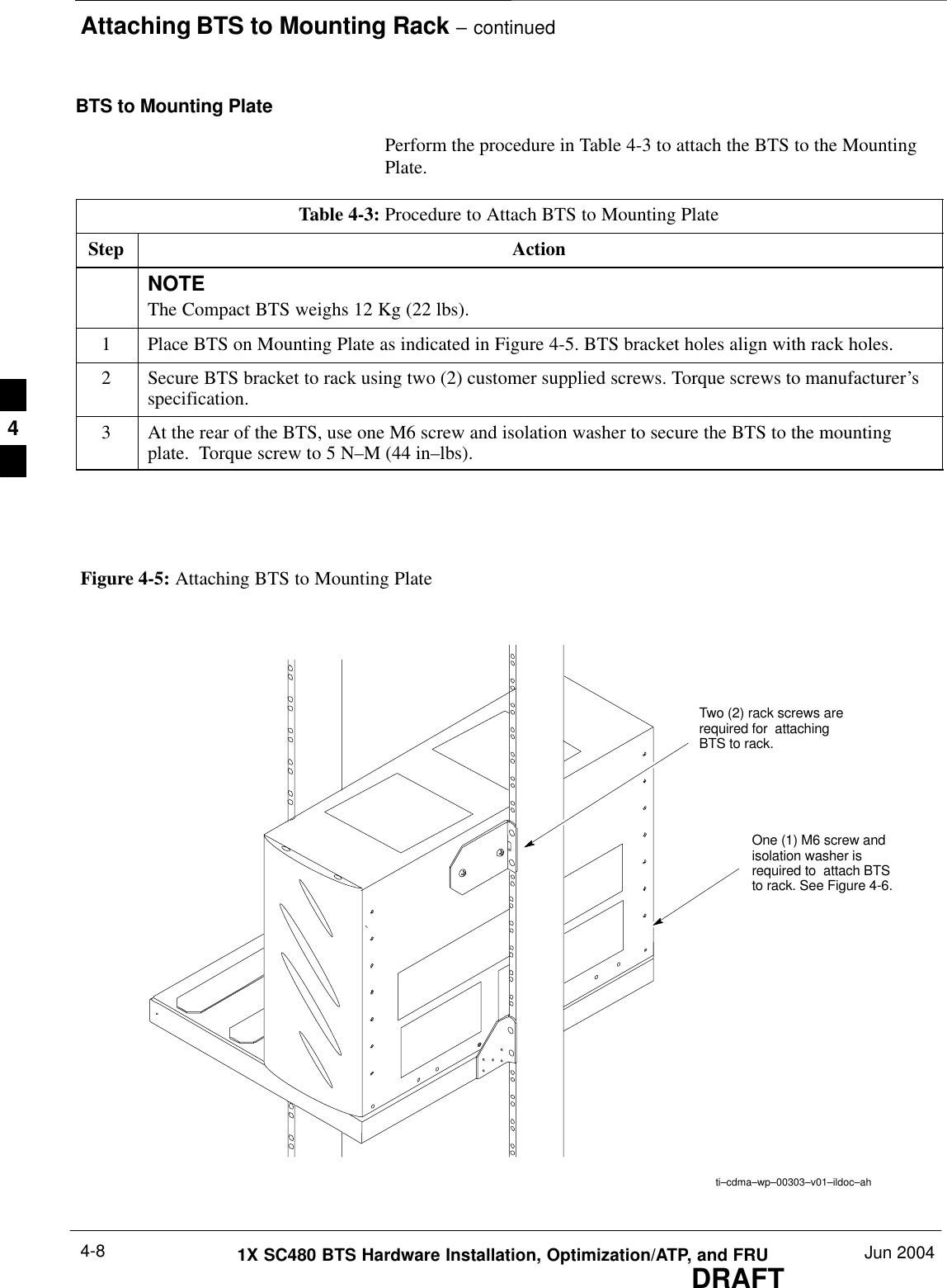
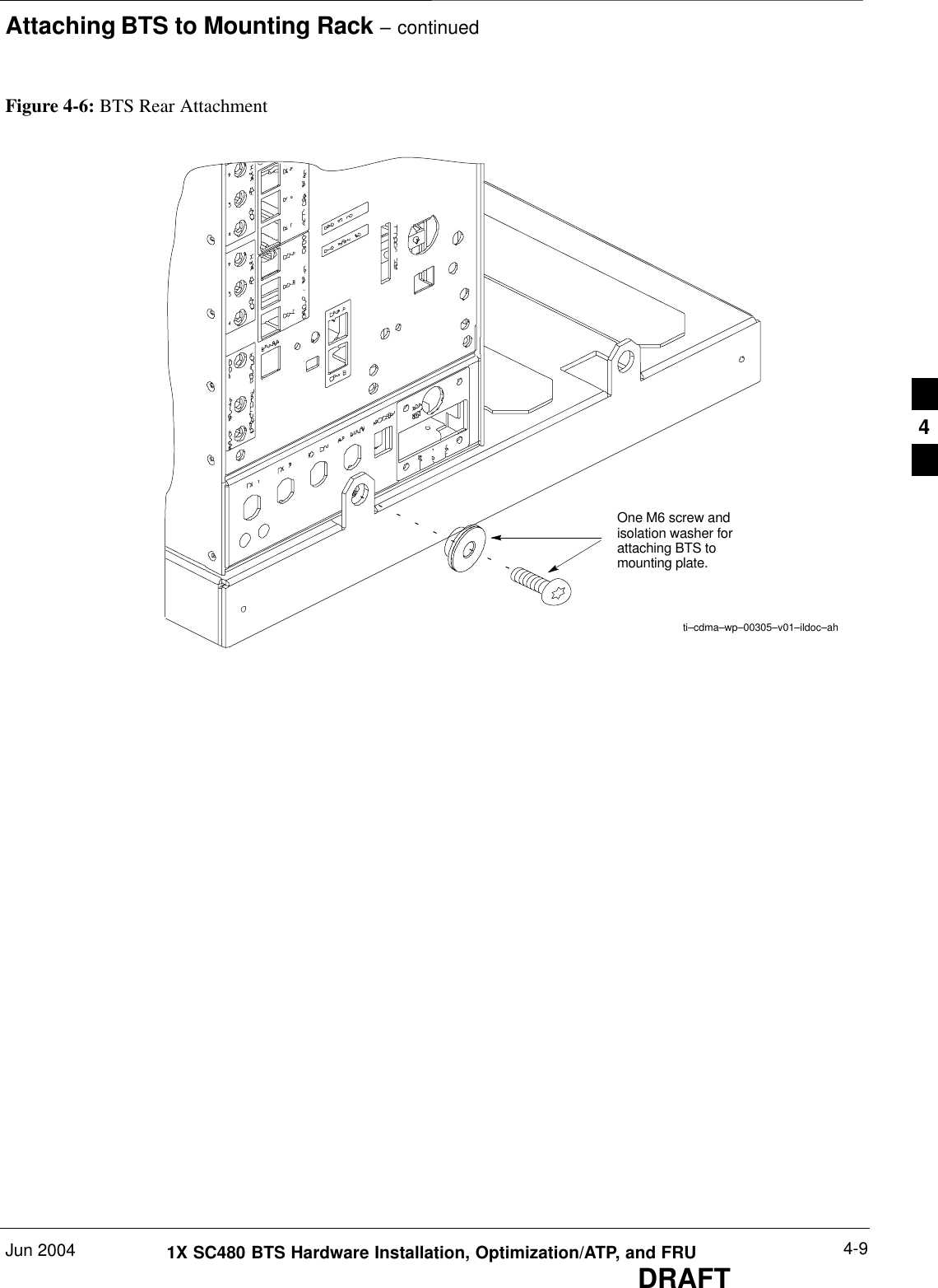
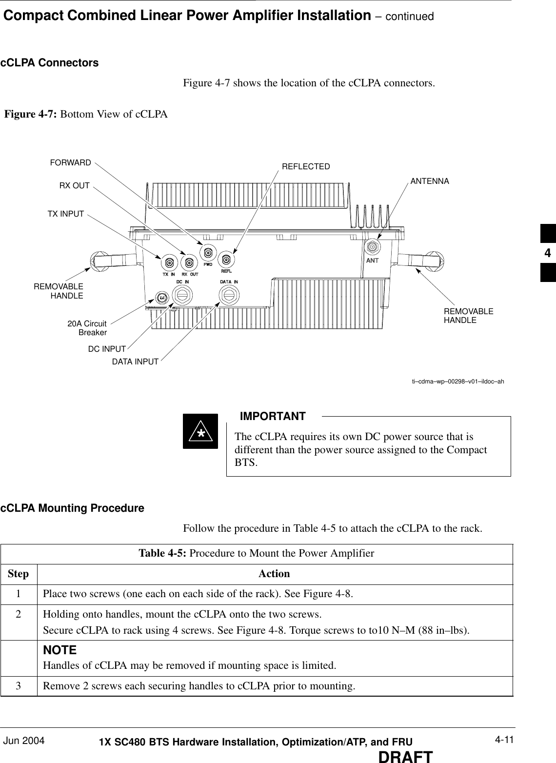
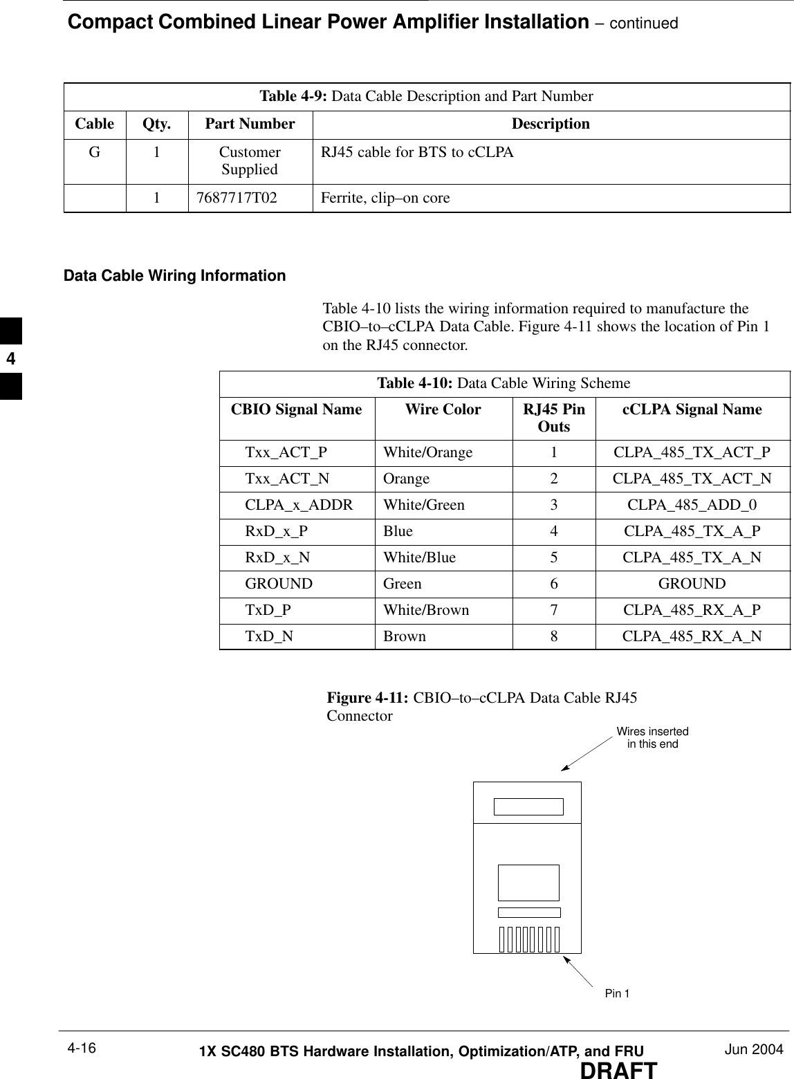
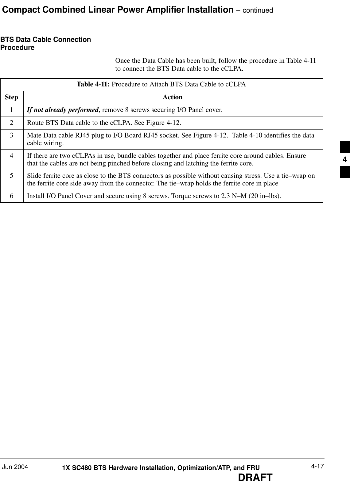
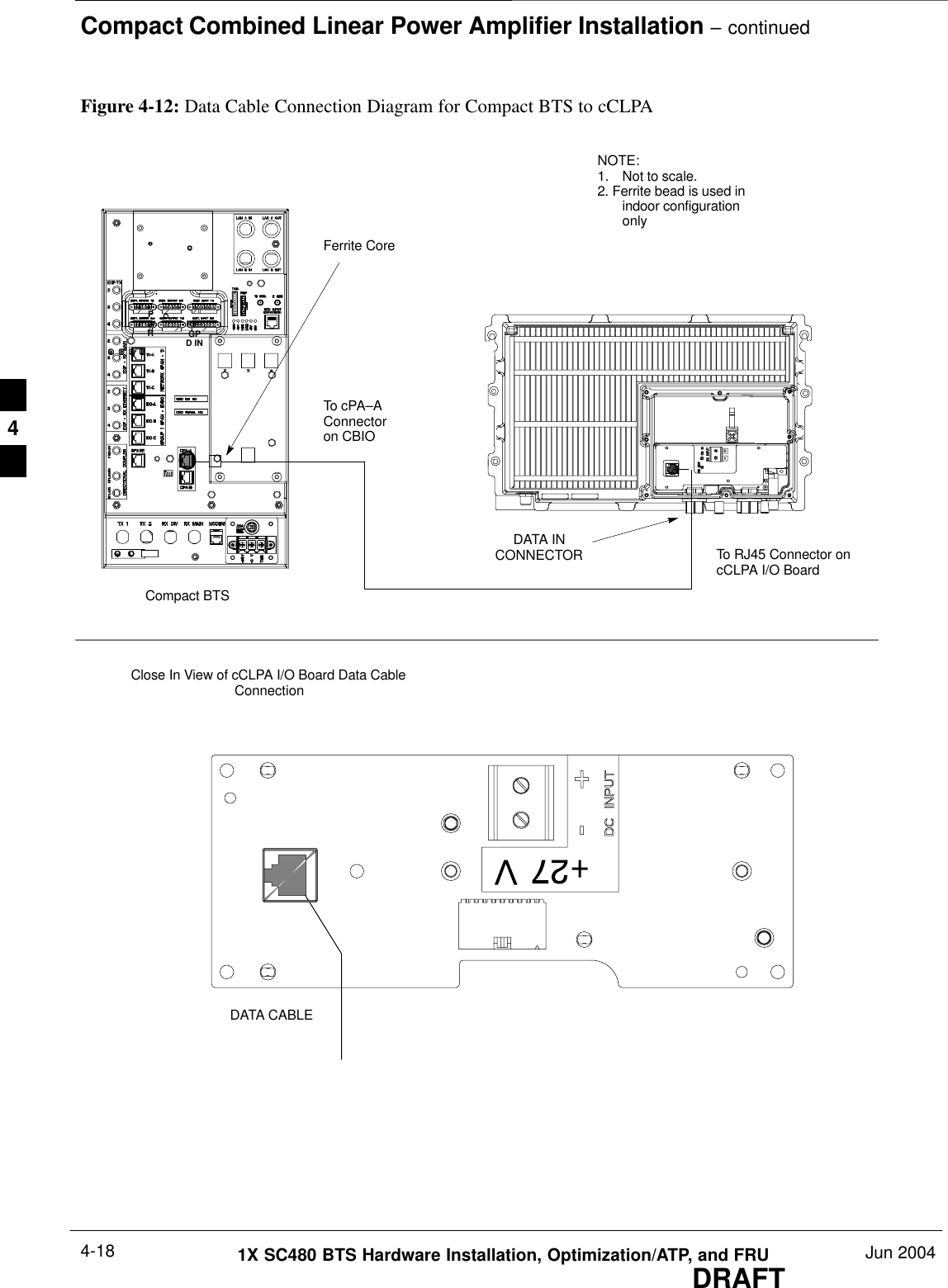
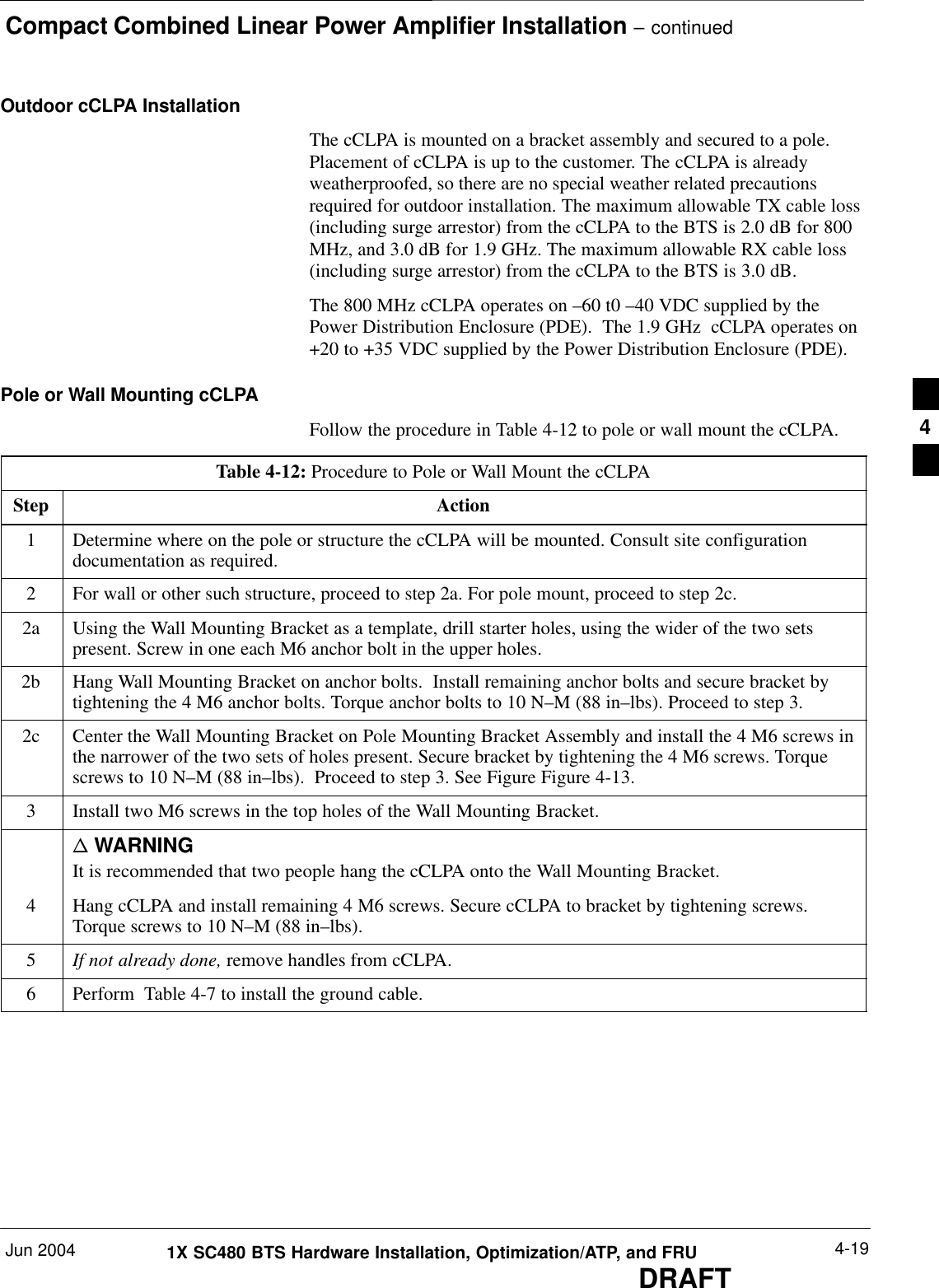
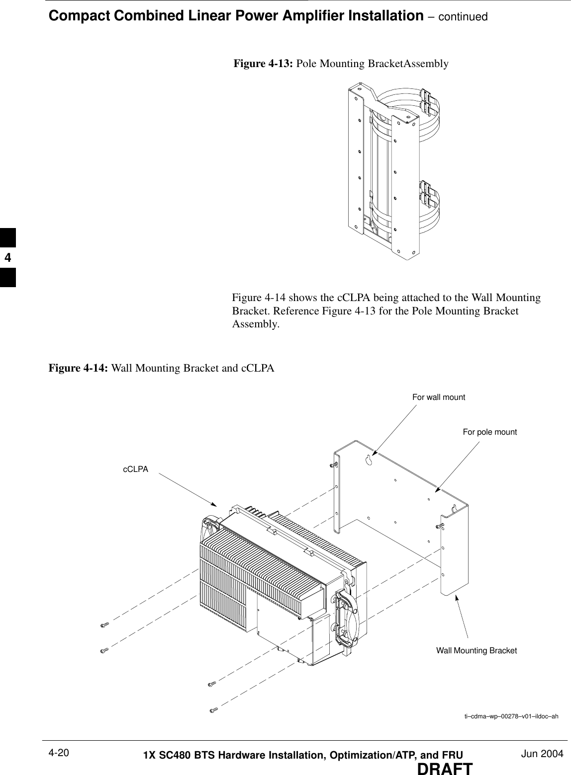
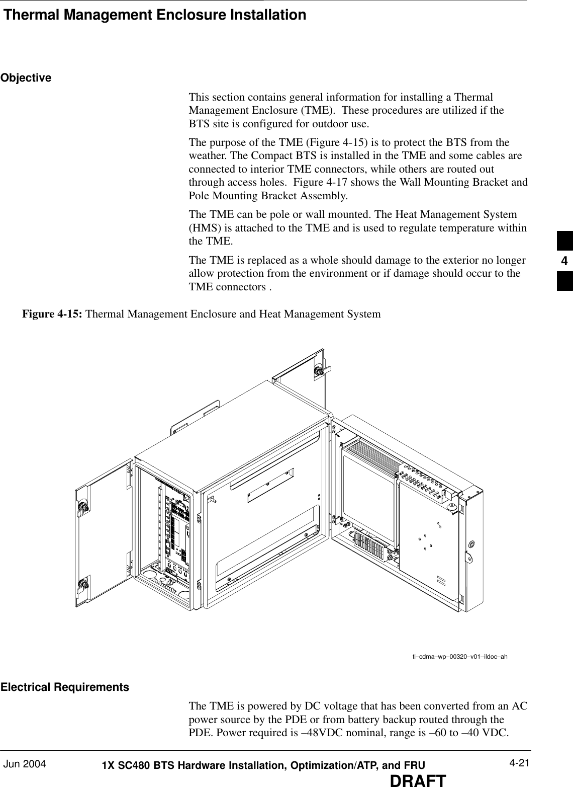
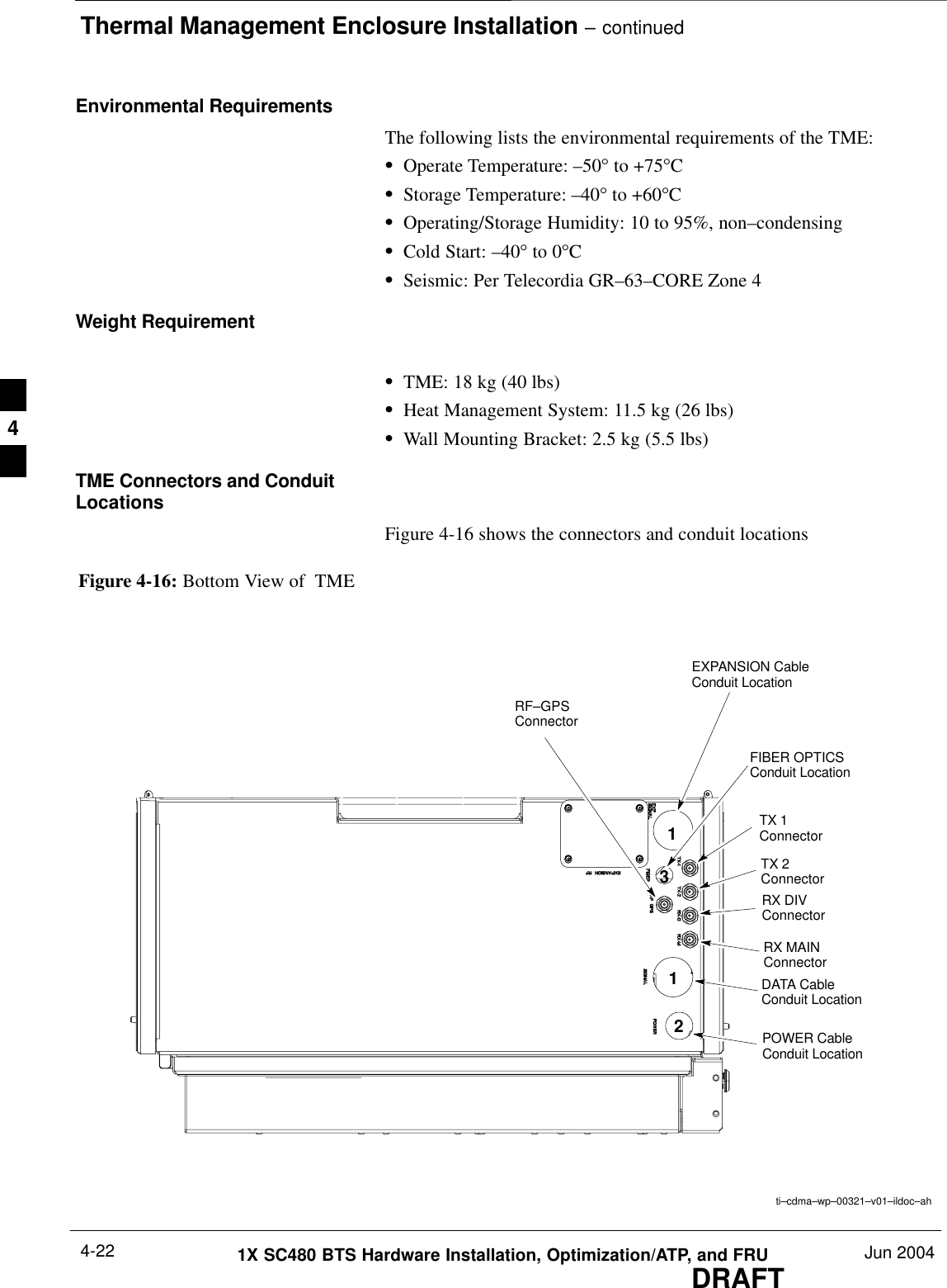
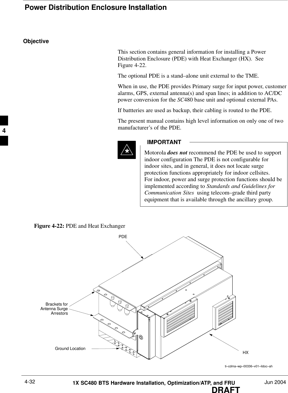
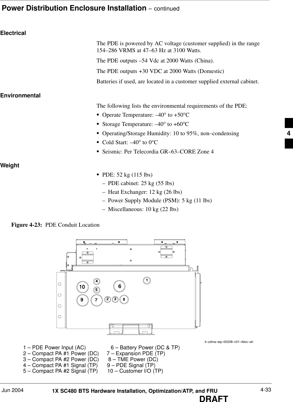
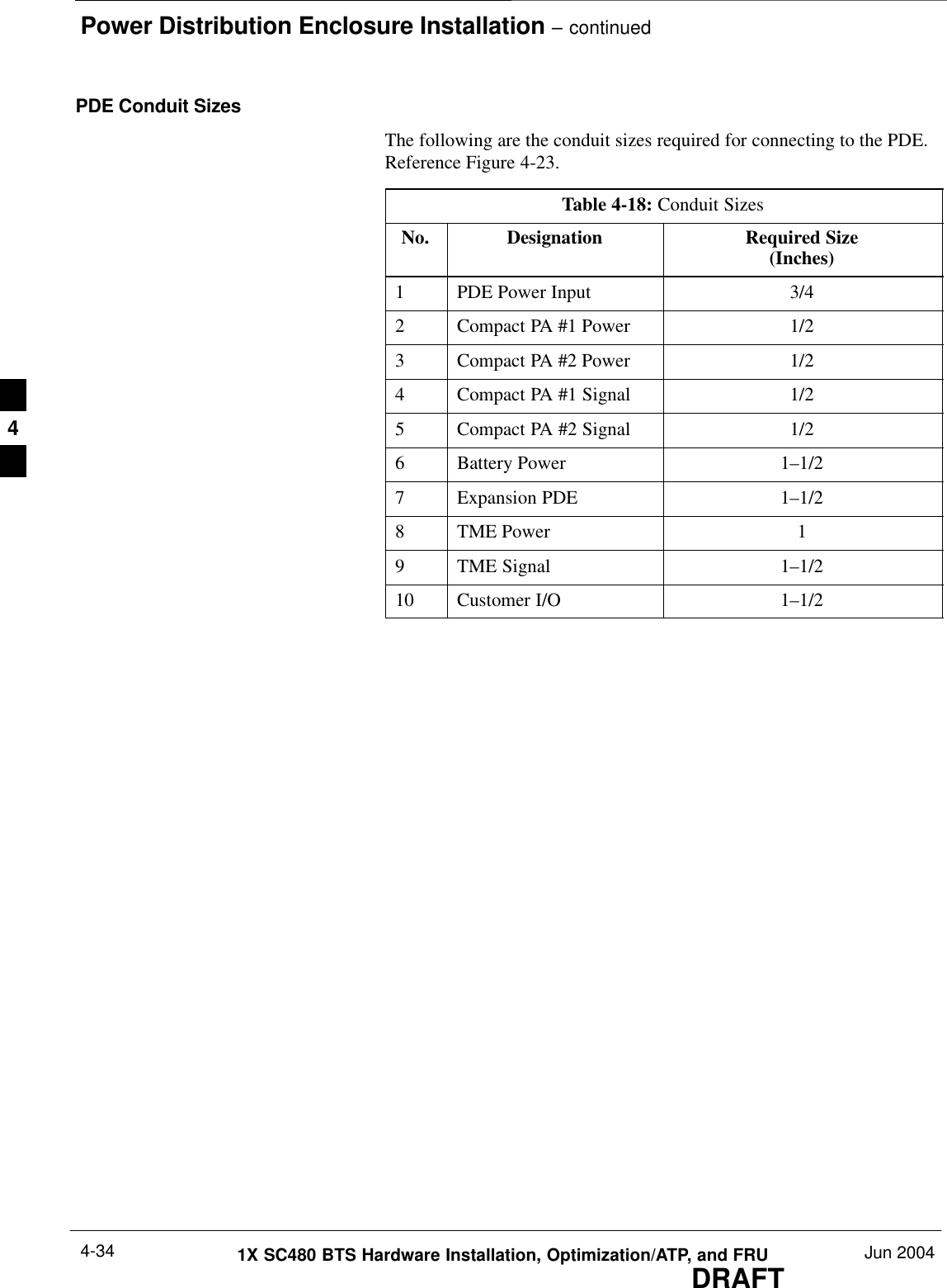
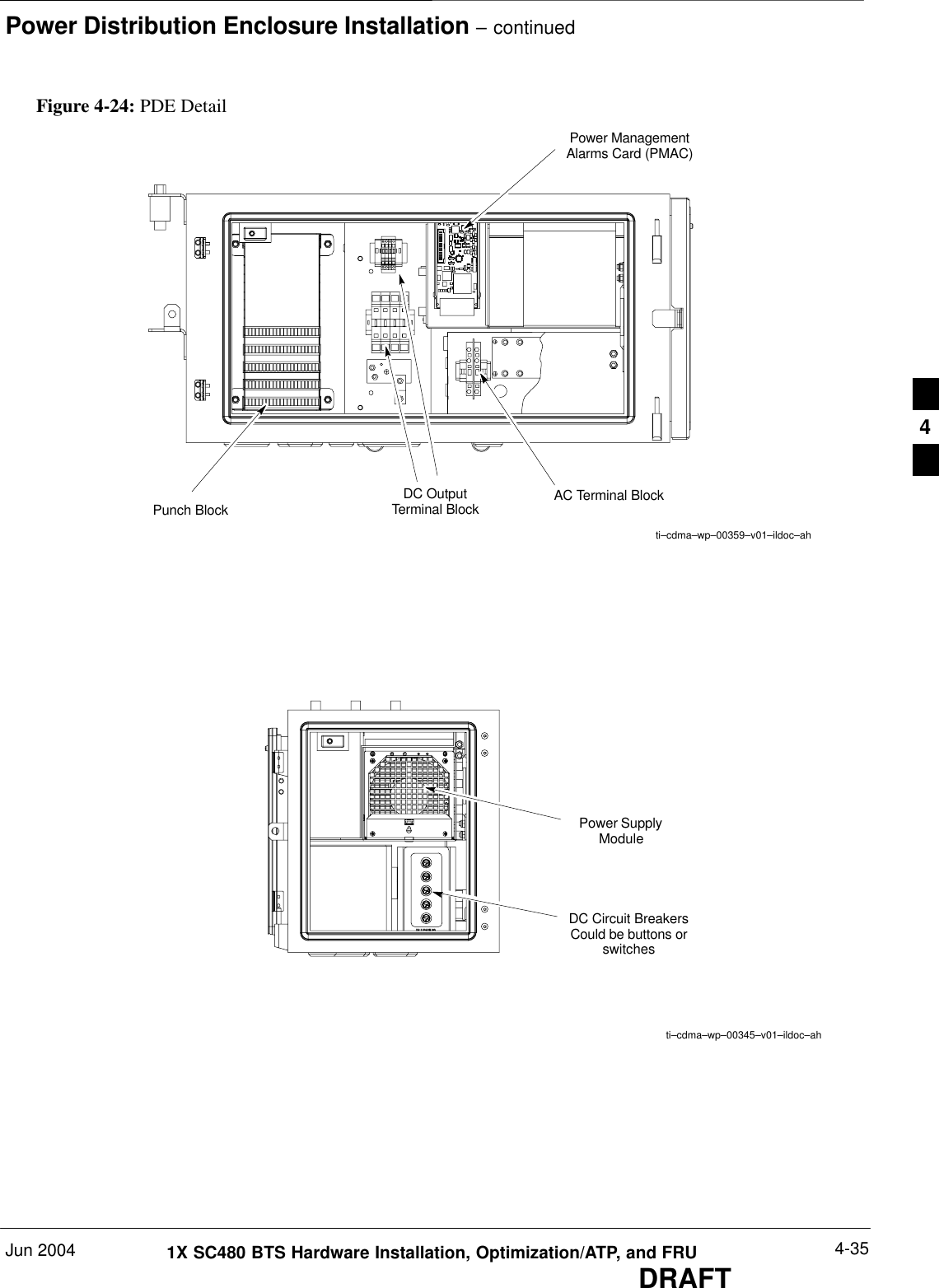
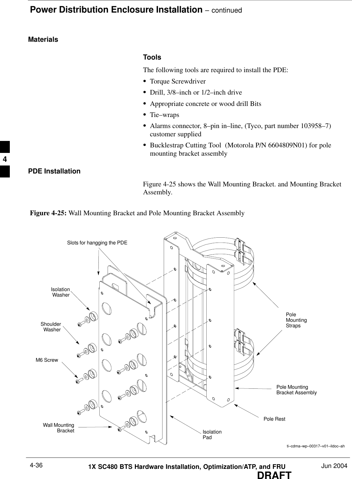
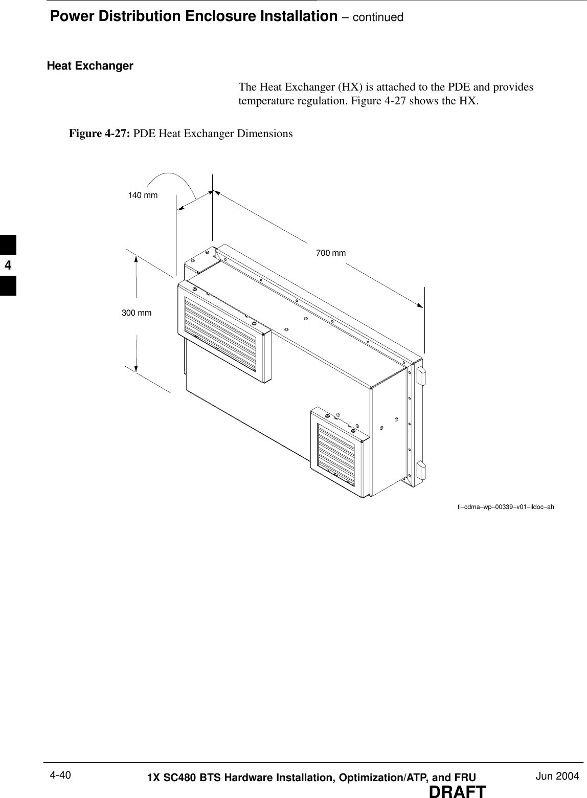
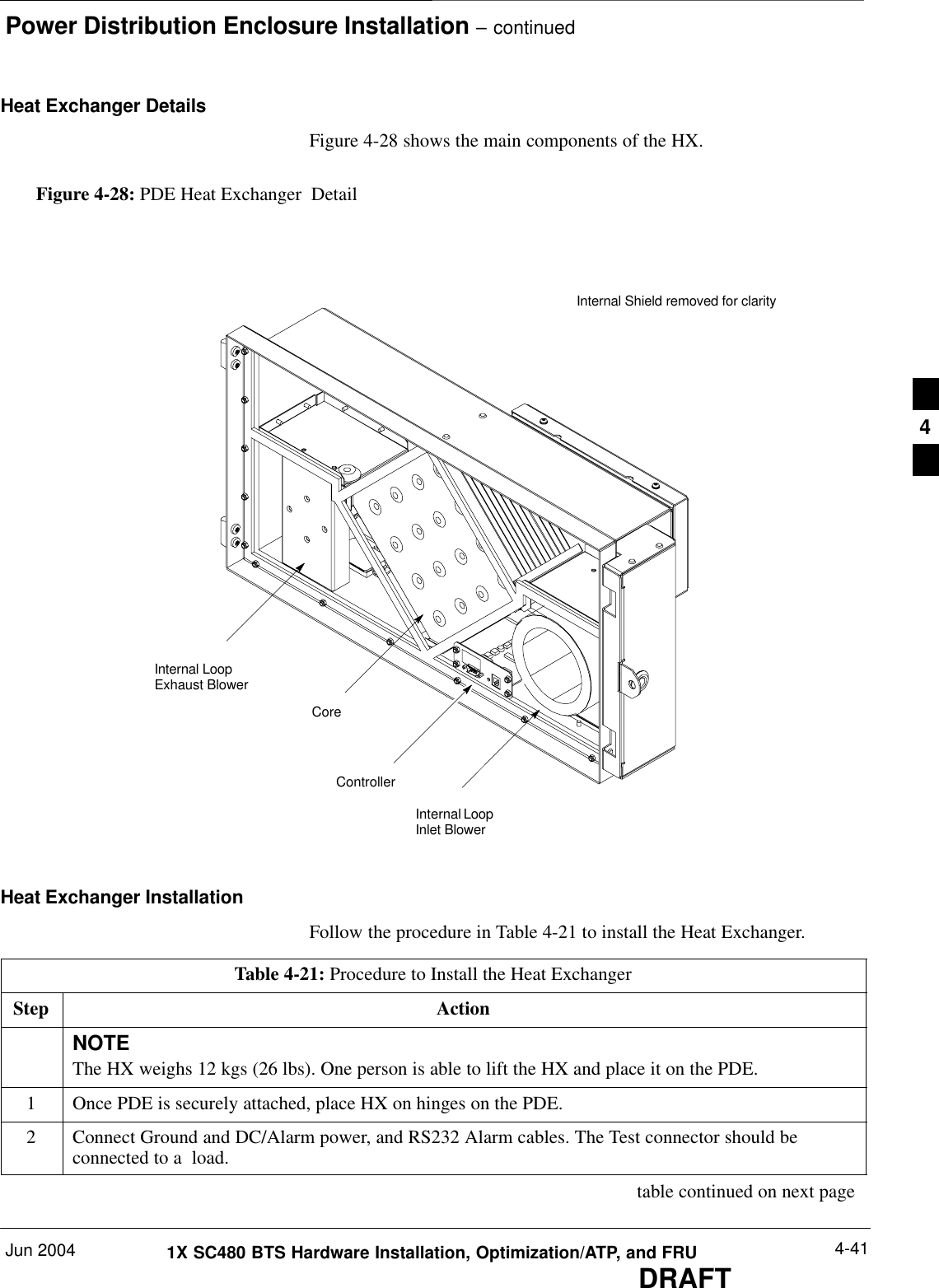
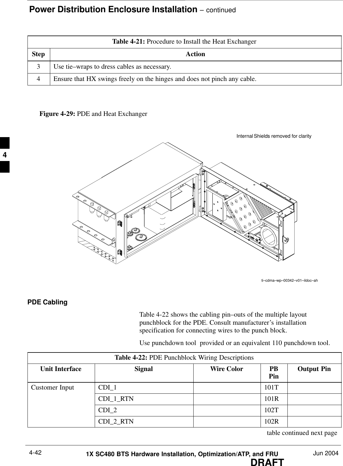
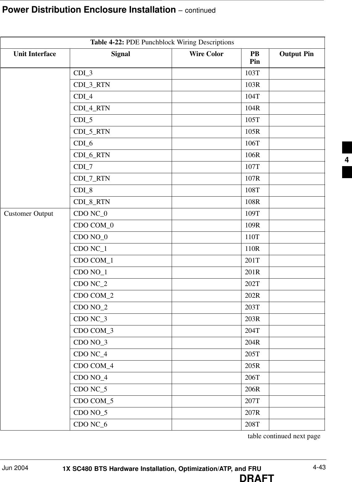
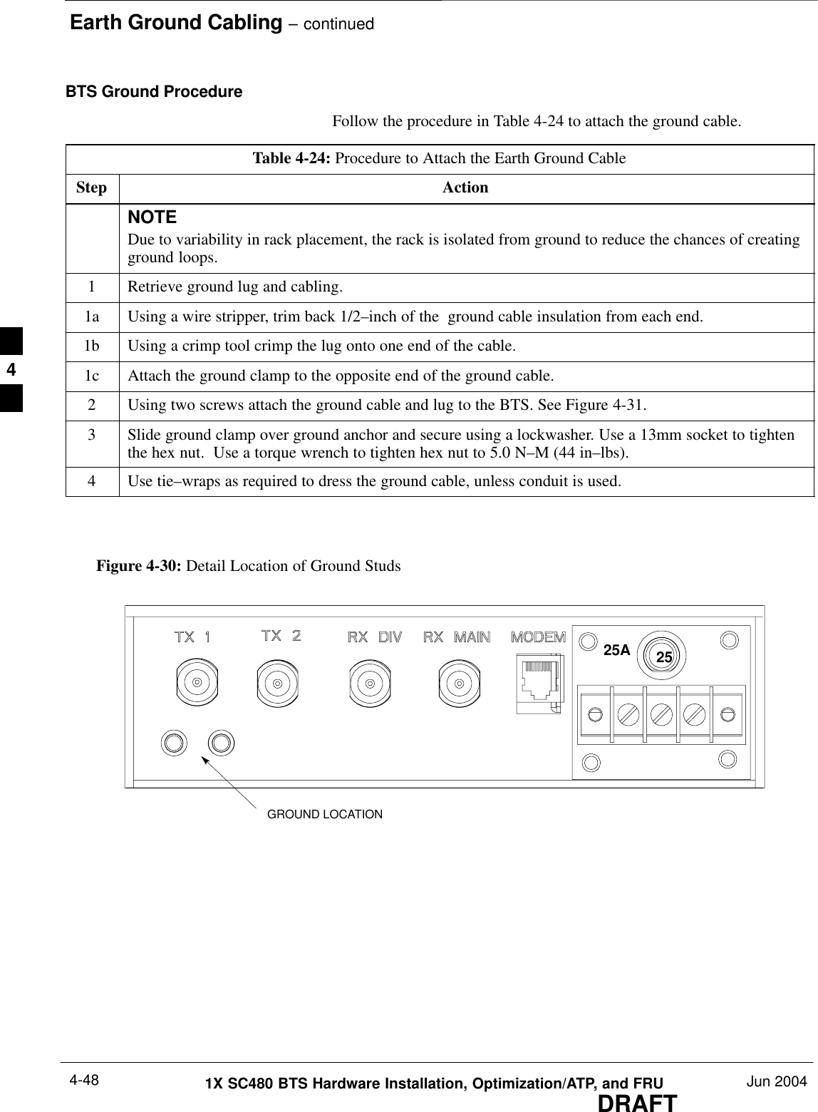
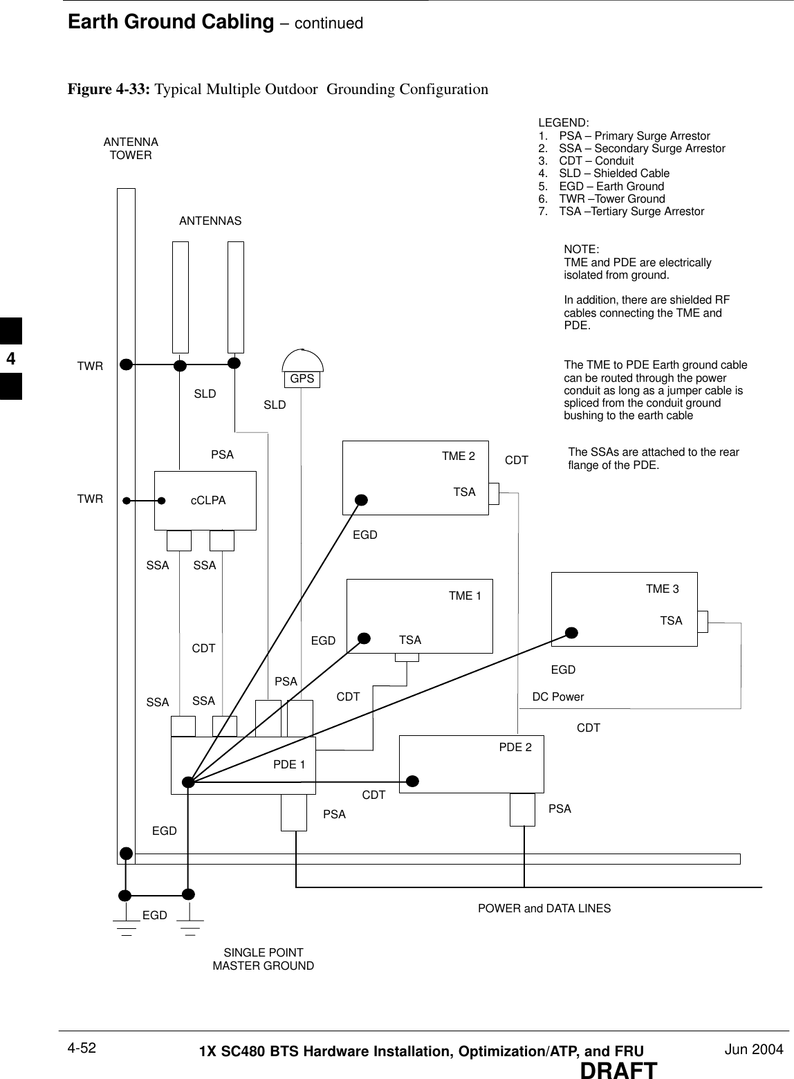
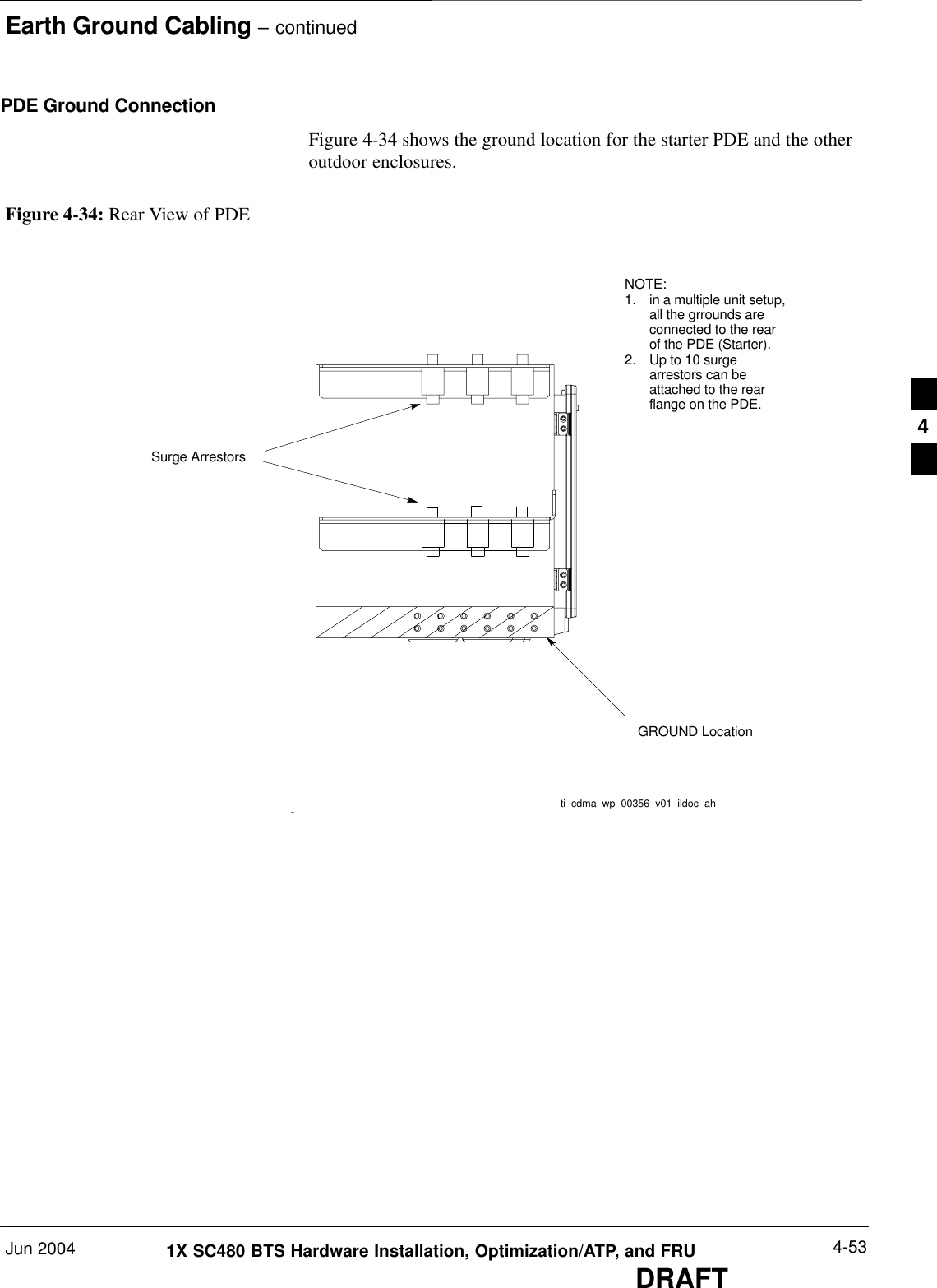
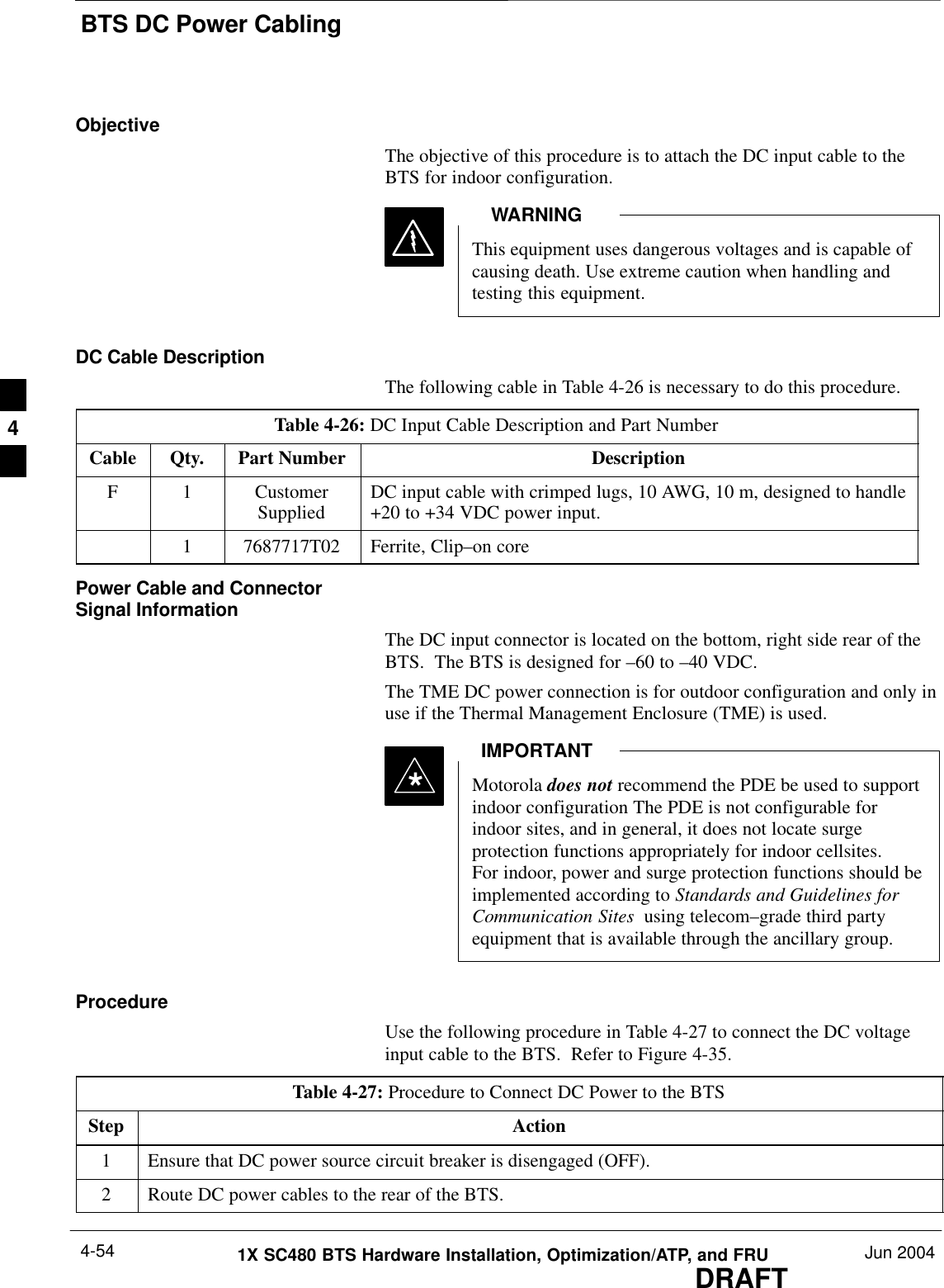
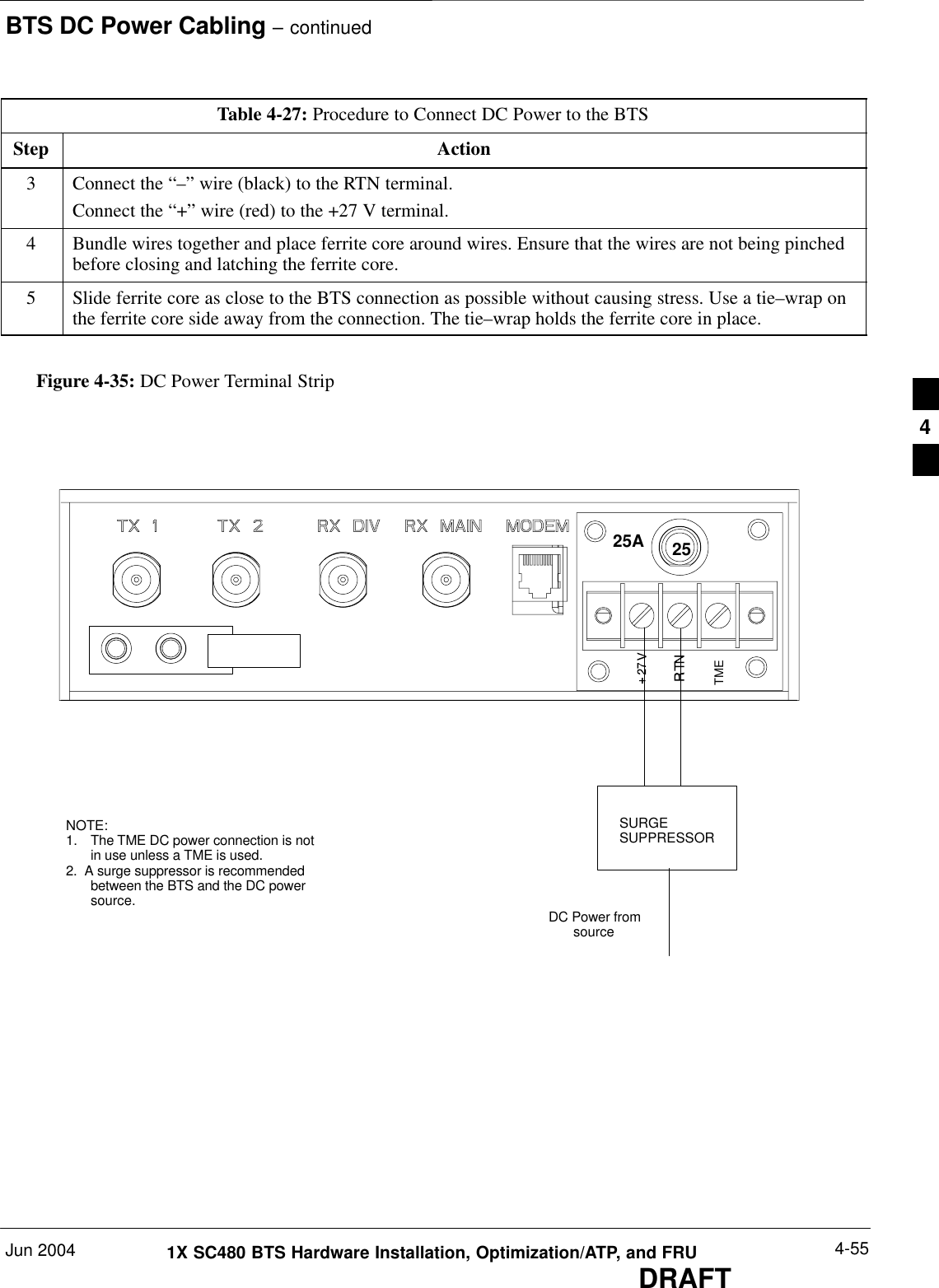
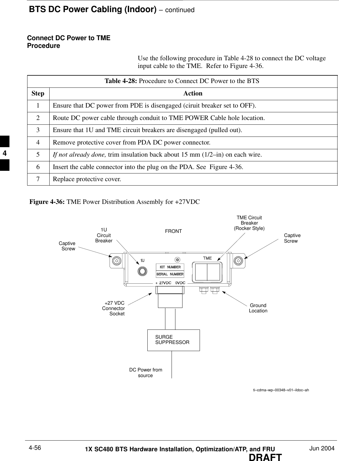
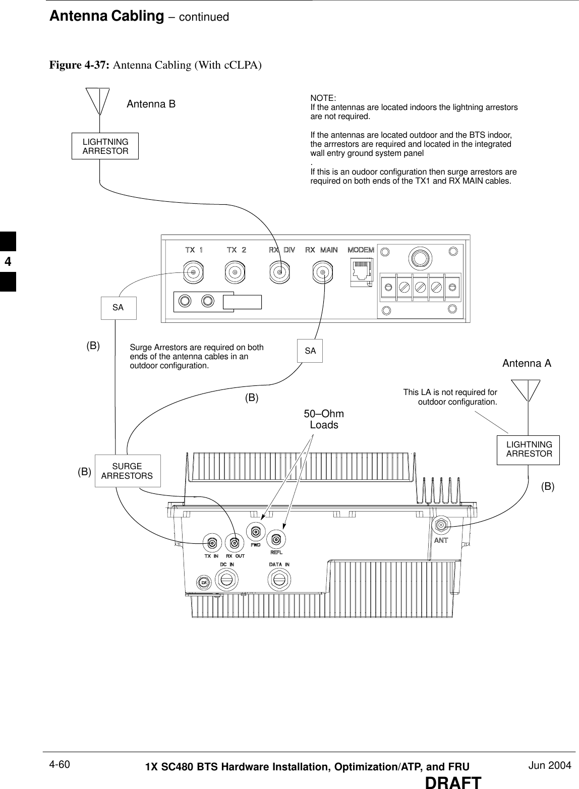
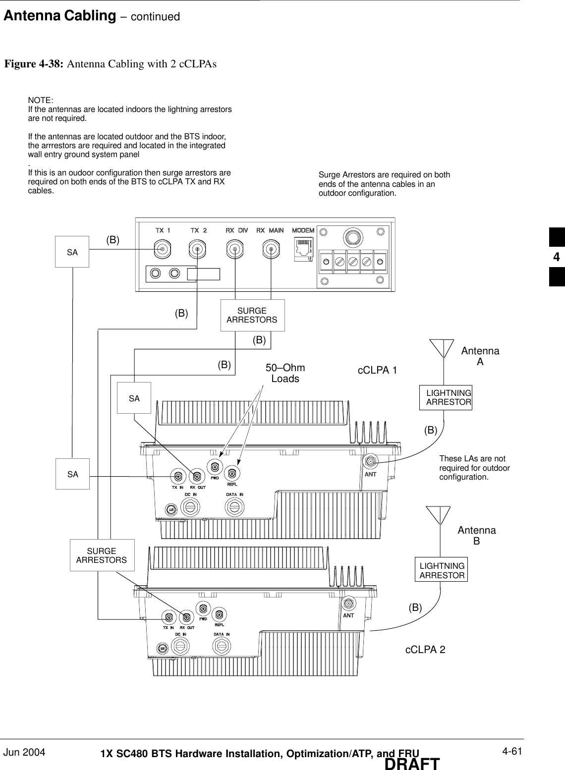
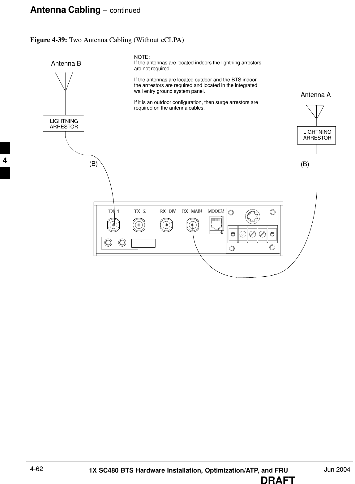
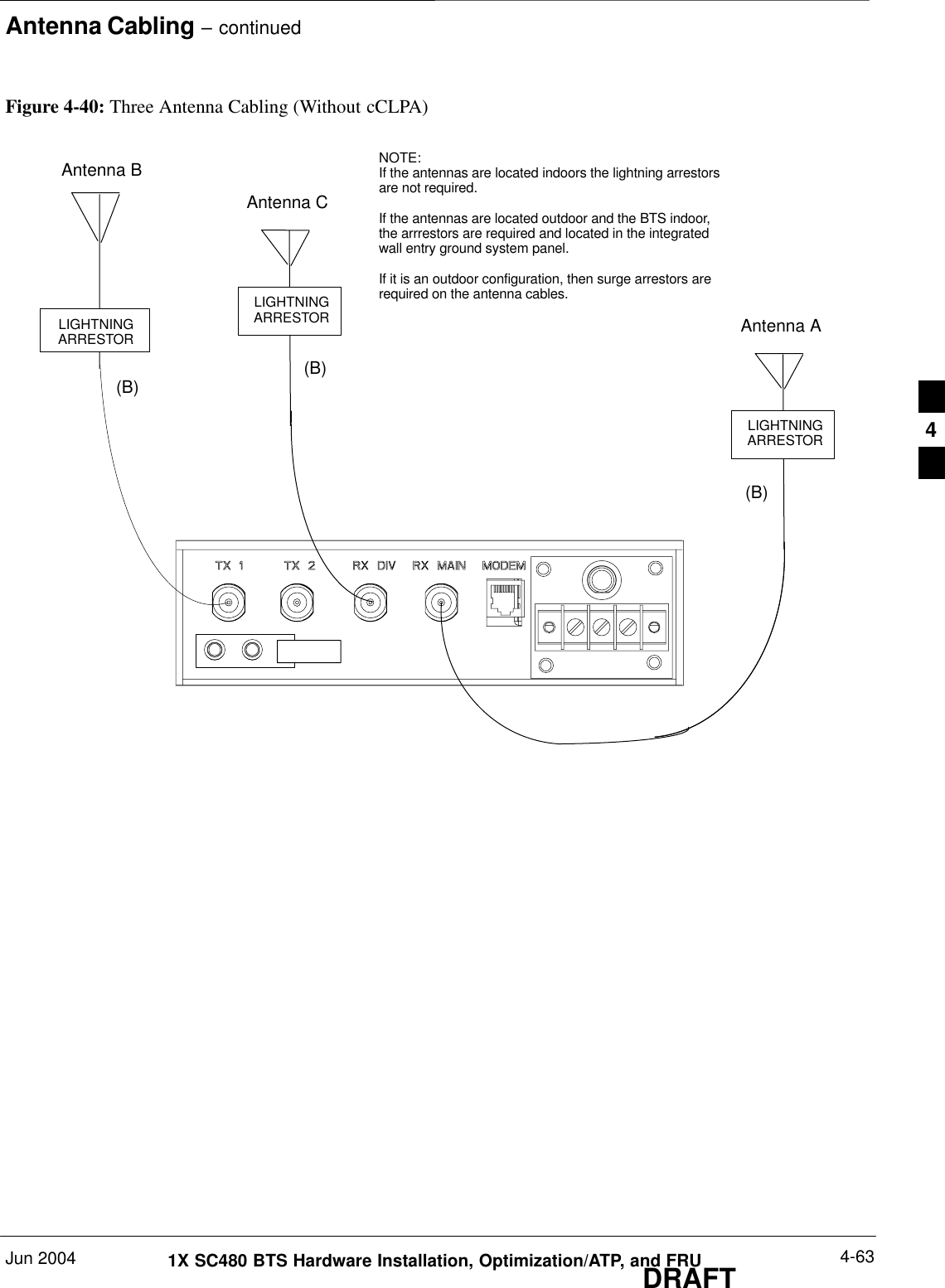
DRAFT68P09262A08–1JUN 2004ENGLISHCDMA2000 1XSOFTWARE RELEASE 2.16.5.XTechnicalInformation1X SC480 BTS HARDWAREINSTALLATION, OPTIMIZATION/ATP, ANDFRU1.9 GHZ
DRAFTSPECIFICATIONS SUBJECT TO CHANGE WITHOUT NOTICENoticeWhile reasonable efforts have been made to assure the accuracy of this document, Motorola, Inc. assumes no liability resulting from anyinaccuracies or omissions in this document, or from use of the information obtained herein. The information in this document has beencarefully checked and is believed to be entirely reliable. However, no responsibility is assumed for inaccuracies or omissions. Motorola,Inc. reserves the right to make changes to any products described herein and reserves the right to revise this document and to makechanges from time to time in content hereof with no obligation to notify any person of revisions or changes. Motorola, Inc. does notassume any liability arising out of the application or use of any product, software, or circuit described herein; neither does it conveylicense under its patent rights or the rights of others.It is possible that this publication may contain references to, or information about Motorola products (machines and programs),programming, or services that are not announced in your country. Such references or information must not be construed to meanthat Motorola intends to announce such Motorola products, programming, or services in your country.CopyrightsThis instruction manual, and the Motorola products described in this instruction manual may be, include or describe copyrightedMotorola material, such as computer programs stored in semiconductor memories or other media. Laws in the United States andother countries preserve for Motorola and its licensors certain exclusive rights for copyrighted material, including the exclusiveright to copy, reproduce in any form, distribute and make derivative works of the copyrighted material. Accordingly, anycopyrighted material of Motorola and its licensors contained herein or in the Motorola products described in this instruction manualmay not be copied, reproduced, distributed, merged or modified in any manner without the express written permission of Motorola.Furthermore, the purchase of Motorola products shall not be deemed to grant either directly or by implication, estoppel, orotherwise, any license under the copyrights, patents or patent applications of Motorola, as arises by operation of law in the sale of aproduct.Usage and Disclosure RestrictionsLicense AgreementThe software described in this document is the property of Motorola, Inc and its licensors. It is furnished by express licenseagreement only and may be used only in accordance with the terms of such an agreement.Copyrighted MaterialsSoftware and documentation are copyrighted materials. Making unauthorized copies is prohibited by law. No part of the software ordocumentation may be reproduced, transmitted, transcribed, stored in a retrieval system, or translated into any language orcomputer language, in any form or by any means, without prior written permission of Motorola, Inc.High Risk ActivitiesComponents, units, or third–party products used in the product described herein are NOT fault–tolerant and are NOT designed,manufactured, or intended for use as on–line control equipment in the following hazardous environments requiring fail–safecontrols: the operation of Nuclear Facilities, Aircraft Navigation or Aircraft Communication Systems, Air Traffic Control, LifeSupport, or Weapons Systems (“High Risk Activities”). Motorola and its supplier(s) specifically disclaim any expressed or impliedwarranty of fitness for such High Risk Activities.TrademarksMOTOROLA and the Stylized M Logo are registered in the US Patent & Trademark Office. All other product or service names arethe property of their respective owners.© Copyright 2003, 2004 Motorola, Inc.Javat Technology and/or J2MEt: Java and all other Java–based marks are trademarks or registered trademarks of SunMicrosystems, Inc. in the U.S. and other countries.UNIXR: UNIX is a registered trademark of The Open Group in the United States and other countries.REV091302
Jun 2004 1X SC480 BTS Hardware Installation, Optimization/ATP, and FRU  iDRAFTTable of Contents1X SC480 BTS Hardware Installation, Optimization/ATP, and FRUSoftware Release 2.16.5.XList of Figures vi . . . . . . . . . . . . . . . . . . . . . . . . . . . . . . . . . . . . . . . . . . . . . . . . . . . List of Tables xii . . . . . . . . . . . . . . . . . . . . . . . . . . . . . . . . . . . . . . . . . . . . . . . . . . . Foreword xxi . . . . . . . . . . . . . . . . . . . . . . . . . . . . . . . . . . . . . . . . . . . . . . . . . . . . . . . FCC Requirements xxiii . . . . . . . . . . . . . . . . . . . . . . . . . . . . . . . . . . . . . . . . . . . . . . . General Safety xxvi . . . . . . . . . . . . . . . . . . . . . . . . . . . . . . . . . . . . . . . . . . . . . . . . . . . Revision History xxviii . . . . . . . . . . . . . . . . . . . . . . . . . . . . . . . . . . . . . . . . . . . . . . . . . Chapter 1: Introduction Introduction 1-1 . . . . . . . . . . . . . . . . . . . . . . . . . . . . . . . . . . . . . . . . . . . . . . . . . . . . . Required Documents 1-5 . . . . . . . . . . . . . . . . . . . . . . . . . . . . . . . . . . . . . . . . . . . . . . CDMA 1.9 GHz Operating Frequency Programming Information 1-8 . . . . . . . . . . Installation Tools and Materials 1-11 . . . . . . . . . . . . . . . . . . . . . . . . . . . . . . . . . . . . . ATP Tools and Materials 1-14 . . . . . . . . . . . . . . . . . . . . . . . . . . . . . . . . . . . . . . . . . . BTS Equipment Identification 1-20 . . . . . . . . . . . . . . . . . . . . . . . . . . . . . . . . . . . . . . Outdoor Enclosure Equipment Identification 1-29 . . . . . . . . . . . . . . . . . . . . . . . . . . . Installation and ATP Order 1-32 . . . . . . . . . . . . . . . . . . . . . . . . . . . . . . . . . . . . . . . . . Chapter 2: Site Preparation Site Preparation Overview 2-1 . . . . . . . . . . . . . . . . . . . . . . . . . . . . . . . . . . . . . . . . . Site Inspections 2-2 . . . . . . . . . . . . . . . . . . . . . . . . . . . . . . . . . . . . . . . . . . . . . . . . . . Prepare Site for the Arrival of the Equipment 2-5 . . . . . . . . . . . . . . . . . . . . . . . . . . Unpacking the Equipment 2-7 . . . . . . . . . . . . . . . . . . . . . . . . . . . . . . . . . . . . . . . . . Dimensions and Clearances 2-14 . . . . . . . . . . . . . . . . . . . . . . . . . . . . . . . . . . . . . . . . Chapter 3: BTS Cables Cable Description 3-1 . . . . . . . . . . . . . . . . . . . . . . . . . . . . . . . . . . . . . . . . . . . . . . . . Power, Earth Ground, and Battery Cabling 3-4 . . . . . . . . . . . . . . . . . . . . . . . . . . . . Antenna Cabling 3-6 . . . . . . . . . . . . . . . . . . . . . . . . . . . . . . . . . . . . . . . . . . . . . . . . . Span Line Cabling 3-7 . . . . . . . . . . . . . . . . . . . . . . . . . . . . . . . . . . . . . . . . . . . . . . . Remote GPS Head and Cabling 3-8 . . . . . . . . . . . . . . . . . . . . . . . . . . . . . . . . . . . . . Local GPS (RF–GPS) Antenna Cabling 3-11 . . . . . . . . . . . . . . . . . . . . . . . . . . . . . . .
Table of Contents – continued ii 1X SC480 BTS Hardware Installation, Optimization/ATP, and FRU Jun 2004DRAFTChapter 4: BTS and Cabling Installation Installation Overview 4-1 . . . . . . . . . . . . . . . . . . . . . . . . . . . . . . . . . . . . . . . . . . . . . Connector Locations 4-3 . . . . . . . . . . . . . . . . . . . . . . . . . . . . . . . . . . . . . . . . . . . . . . Attaching BTS to Mounting Rack 4-5 . . . . . . . . . . . . . . . . . . . . . . . . . . . . . . . . . . . Compact Combined Linear Power Amplifier Installation 4-10 . . . . . . . . . . . . . . . . . Thermal Management Enclosure Installation 4-21 . . . . . . . . . . . . . . . . . . . . . . . . . . . Compact BTS and HMS Installation 4-28 . . . . . . . . . . . . . . . . . . . . . . . . . . . . . . . . . Power Distribution Enclosure Installation 4-32 . . . . . . . . . . . . . . . . . . . . . . . . . . . . . Earth Ground Cabling 4-47 . . . . . . . . . . . . . . . . . . . . . . . . . . . . . . . . . . . . . . . . . . . . . BTS DC Power Cabling 4-54 . . . . . . . . . . . . . . . . . . . . . . . . . . . . . . . . . . . . . . . . . . . AC / DC Power Cabling Installation 4-57 . . . . . . . . . . . . . . . . . . . . . . . . . . . . . . . . . Antenna  Cabling 4-59 . . . . . . . . . . . . . . . . . . . . . . . . . . . . . . . . . . . . . . . . . . . . . . . . Span Line, RGPS, and RF GPS Cabling 4-64 . . . . . . . . . . . . . . . . . . . . . . . . . . . . . . Customer Input / Output Cables 4-76 . . . . . . . . . . . . . . . . . . . . . . . . . . . . . . . . . . . . . Site Cleanup 4-78 . . . . . . . . . . . . . . . . . . . . . . . . . . . . . . . . . . . . . . . . . . . . . . . . . . . . Installation Completion Checklist 4-79 . . . . . . . . . . . . . . . . . . . . . . . . . . . . . . . . . . . Chapter 5: Power Installation Frame Configuration DIP Switch 5-1 . . . . . . . . . . . . . . . . . . . . . . . . . . . . . . . . . . . . Pre–Power Up Test (Indoor) 5-4 . . . . . . . . . . . . . . . . . . . . . . . . . . . . . . . . . . . . . . . . AC Power Input (Outdoor Configuration) 5-7 . . . . . . . . . . . . . . . . . . . . . . . . . . . . . Battery Backup DC Power Input (Outdoor Configuration) 5-9 . . . . . . . . . . . . . . . . Initial Power–Up Test 5-11 . . . . . . . . . . . . . . . . . . . . . . . . . . . . . . . . . . . . . . . . . . . . . Remove Power 5-14 . . . . . . . . . . . . . . . . . . . . . . . . . . . . . . . . . . . . . . . . . . . . . . . . . . Chapter 6: Optimization and Calibration Preliminary Operations: Overview 6-1 . . . . . . . . . . . . . . . . . . . . . . . . . . . . . . . . . . . Preliminary Operations: Overview 6-2 . . . . . . . . . . . . . . . . . . . . . . . . . . . . . . . . . . . Ethernet LAN 6-3 . . . . . . . . . . . . . . . . . . . . . . . . . . . . . . . . . . . . . . . . . . . . . . . . . . . Introduction to Optimization and Calibration 6-4 . . . . . . . . . . . . . . . . . . . . . . . . . . Preparing the LMF 6-7 . . . . . . . . . . . . . . . . . . . . . . . . . . . . . . . . . . . . . . . . . . . . . . . Span Lines – Interface and Isolation 6-16 . . . . . . . . . . . . . . . . . . . . . . . . . . . . . . . . . . LMF to BTS Connection 6-17 . . . . . . . . . . . . . . . . . . . . . . . . . . . . . . . . . . . . . . . . . . Using the LMF 6-18 . . . . . . . . . . . . . . . . . . . . . . . . . . . . . . . . . . . . . . . . . . . . . . . . . . Pinging the Processors 6-33 . . . . . . . . . . . . . . . . . . . . . . . . . . . . . . . . . . . . . . . . . . . . Pinging the Processors 6-34 . . . . . . . . . . . . . . . . . . . . . . . . . . . . . . . . . . . . . . . . . . . . Download the BTS 6-36 . . . . . . . . . . . . . . . . . . . . . . . . . . . . . . . . . . . . . . . . . . . . . . . CSA System Time – GPS & HSO/MSO Verification 6-43 . . . . . . . . . . . . . . . . . . . .
Table of Contents – continuedJun 2004 1X SC480 BTS Hardware Installation, Optimization/ATP, and FRU  iiiDRAFTTest Equipment Setup 6-51 . . . . . . . . . . . . . . . . . . . . . . . . . . . . . . . . . . . . . . . . . . . . . Test Set Calibration 6-65 . . . . . . . . . . . . . . . . . . . . . . . . . . . . . . . . . . . . . . . . . . . . . . . Bay Level Offset Calibration 6-76 . . . . . . . . . . . . . . . . . . . . . . . . . . . . . . . . . . . . . . . Chapter 7: Automated Acceptance Test Procedure (ATP) Automated Acceptance Test Procedure – Introduction 7-1 . . . . . . . . . . . . . . . . . . . . Acceptance Tests – Test Set Up 7-4 . . . . . . . . . . . . . . . . . . . . . . . . . . . . . . . . . . . . . Abbreviated (All–inclusive) Acceptance Tests 7-5 . . . . . . . . . . . . . . . . . . . . . . . . . . Individual Acceptance Tests–Introduction 7-9 . . . . . . . . . . . . . . . . . . . . . . . . . . . . . TX Spectral Purity Transmit Mask Acceptance Test 7-11 . . . . . . . . . . . . . . . . . . . . . TX Waveform Quality (Rho) Acceptance Test 7-14 . . . . . . . . . . . . . . . . . . . . . . . . . . TX Pilot Time Offset Acceptance Test 7-16 . . . . . . . . . . . . . . . . . . . . . . . . . . . . . . . . TX Code Domain Power/Noise Floor Acceptance Test 7-18 . . . . . . . . . . . . . . . . . . . RX FER Acceptance Test 7-21 . . . . . . . . . . . . . . . . . . . . . . . . . . . . . . . . . . . . . . . . . . Generating an ATP Report 7-23 . . . . . . . . . . . . . . . . . . . . . . . . . . . . . . . . . . . . . . . . . Chapter 8: Leave the Site Updating Calibration Data Files 8-1 . . . . . . . . . . . . . . . . . . . . . . . . . . . . . . . . . . . . . Prepare to Leave the Site 8-3 . . . . . . . . . . . . . . . . . . . . . . . . . . . . . . . . . . . . . . . . . . Chapter 9: Field Replaceable Unit Introduction 9-1 . . . . . . . . . . . . . . . . . . . . . . . . . . . . . . . . . . . . . . . . . . . . . . . . . . . . . Fan Module 9-4 . . . . . . . . . . . . . . . . . . . . . . . . . . . . . . . . . . . . . . . . . . . . . . . . . . . . . High and Medium Stability Oscillator Module 9-7 . . . . . . . . . . . . . . . . . . . . . . . . . Global Positioning System (GPS) Receivers 9-11 . . . . . . . . . . . . . . . . . . . . . . . . . . . RF–GPS Module 9-14 . . . . . . . . . . . . . . . . . . . . . . . . . . . . . . . . . . . . . . . . . . . . . . . . . Power Supply Module (PSM) 9-18 . . . . . . . . . . . . . . . . . . . . . . . . . . . . . . . . . . . . . . . Clock Synchronization Alarms Card 9-21 . . . . . . . . . . . . . . . . . . . . . . . . . . . . . . . . . Group Line Interface Card 9-24 . . . . . . . . . . . . . . . . . . . . . . . . . . . . . . . . . . . . . . . . . Multi–Channel CDMA Card 9-28 . . . . . . . . . . . . . . . . . . . . . . . . . . . . . . . . . . . . . . . Broadband Transceiver Card 9-32 . . . . . . . . . . . . . . . . . . . . . . . . . . . . . . . . . . . . . . . . Compact BTS Multi–Coupler Preselector Card 9-36 . . . . . . . . . . . . . . . . . . . . . . . . . MCC Data Only (MCC–DO) Card 9-41 . . . . . . . . . . . . . . . . . . . . . . . . . . . . . . . . . . . Compact BTS Input and Output Board 9-45 . . . . . . . . . . . . . . . . . . . . . . . . . . . . . . . SDCX  Module 9-50 . . . . . . . . . . . . . . . . . . . . . . . . . . . . . . . . . . . . . . . . . . . . . . . . . . RF Filter Tray 9-55 . . . . . . . . . . . . . . . . . . . . . . . . . . . . . . . . . . . . . . . . . . . . . . . . . . . Compact Combined Linear Power Amplifier 9-67 . . . . . . . . . . . . . . . . . . . . . . . . . . . TME Power Distribution Assembly 9-70 . . . . . . . . . . . . . . . . . . . . . . . . . . . . . . . . . .
Table of Contents – continued iv 1X SC480 BTS Hardware Installation, Optimization/ATP, and FRU Jun 2004DRAFTHeat Management System 9-74 . . . . . . . . . . . . . . . . . . . . . . . . . . . . . . . . . . . . . . . . . Thermal Management Enclosure 9-82 . . . . . . . . . . . . . . . . . . . . . . . . . . . . . . . . . . . . Power Distribution Enclosure 9-85 . . . . . . . . . . . . . . . . . . . . . . . . . . . . . . . . . . . . . . . Master Item Number Failure List 9-86 . . . . . . . . . . . . . . . . . . . . . . . . . . . . . . . . . . . . Chapter 10: Reference Procedures Performed At OMC–R Reference Procedures Performed At OMC–R 10-1 . . . . . . . . . . . . . . . . . . . . . . . . . . Accessing OMC–R CLI Window 10-2 . . . . . . . . . . . . . . . . . . . . . . . . . . . . . . . . . . . . Circuit BTS Shut Down Procedures 10-3 . . . . . . . . . . . . . . . . . . . . . . . . . . . . . . . . . . Circuit BTS Start–Up Procedures 10-23 . . . . . . . . . . . . . . . . . . . . . . . . . . . . . . . . . . . . Packet BTS Shut Down Procedures 10-32 . . . . . . . . . . . . . . . . . . . . . . . . . . . . . . . . . . Packet BTS Start–Up Procedures 10-53 . . . . . . . . . . . . . . . . . . . . . . . . . . . . . . . . . . . . Chapter 11: Basic Troubleshooting Basic Troubleshooting  11-1 . . . . . . . . . . . . . . . . . . . . . . . . . . . . . . . . . . . . . . . . . . . . Appendix A: MCC–Data Only MCC–DO Tests A-1 . . . . . . . . . . . . . . . . . . . . . . . . . . . . . . . . . . . . . . . . . . . . . . . . . Appendix B: Test Equipment Preparation Test Equipment Preparation B-1 . . . . . . . . . . . . . . . . . . . . . . . . . . . . . . . . . . . . . . . . Verifying and Setting GPIB Addresses B-5 . . . . . . . . . . . . . . . . . . . . . . . . . . . . . . . . Test Equipment Connection, Testing, and Control B-17 . . . . . . . . . . . . . . . . . . . . . . . Equipment Calibration B-28 . . . . . . . . . . . . . . . . . . . . . . . . . . . . . . . . . . . . . . . . . . . . Manual Cable Calibration B-32 . . . . . . . . . . . . . . . . . . . . . . . . . . . . . . . . . . . . . . . . . . Appendix C: Download ROM Code Downloading ROM Code C-1 . . . . . . . . . . . . . . . . . . . . . . . . . . . . . . . . . . . . . . . . . . Appendix D: MMI Cable Fabrication MMI Cable Fabrication D-1 . . . . . . . . . . . . . . . . . . . . . . . . . . . . . . . . . . . . . . . . . . . Appendix E: Multiple BTS Configurations Compact BTS Expansion Configuration (Indoor) E-1 . . . . . . . . . . . . . . . . . . . . . . . Multiple Compact BTS Configuration (Outdoor) E-22 . . . . . . . . . . . . . . . . . . . . . . . Appendix F: Logical BTS Configuration Logical BTS LAN Configuration for Compact BTS (Indoor) F-1 . . . . . . . . . . . . . . Appendix G: Integrated BTS Router Preliminary Operations Integrated BTS Router Preliminary Operations – Introduction G-1 . . . . . . . . . . . . . Verify GLI3 Software Version and Span Parameter Settings G-2 . . . . . . . . . . . . . . .
Table of Contents – continuedJun 2004 1X SC480 BTS Hardware Installation, Optimization/ATP, and FRU  vDRAFTChange GLI3 Span Parameter Settings G-6 . . . . . . . . . . . . . . . . . . . . . . . . . . . . . . . Appendix H: Integrated BTS Router Installation Integrated BTS Router Installation – Introduction H-1 . . . . . . . . . . . . . . . . . . . . . . . New Packet BTS Installation with IBR H-2 . . . . . . . . . . . . . . . . . . . . . . . . . . . . . . . BTS Span Connections for IBR H-4 . . . . . . . . . . . . . . . . . . . . . . . . . . . . . . . . . . . . . BTS Span Connections for IBR – One Span H-5 . . . . . . . . . . . . . . . . . . . . . . . . . . . Appendix I: Packet Backhaul Configuration Packet Backhaul BTS  I-1 . . . . . . . . . . . . . . . . . . . . . . . . . . . . . . . . . . . . . . . . . . . . Appendix J: Highway Cell Configuration BTS for Highway Cell Configuration J-1 . . . . . . . . . . . . . . . . . . . . . . . . . . . . . . . . Index
 vi 1X SC480 BTS Hardware Installation, Optimization/ATP, and FRU Jun 2004DRAFTList of Figures1X SC480 BTS Hardware Installation, Optimization/ATP, and FRUSoftware Release 2.16.5.XFCC Label and Location xxv . . . . . . . . . . . . . . . . . . . . . . . . . . . . . . . . . . . . . . . . . . . Figure 1-1: Mounted BTS and Rack 1-4 . . . . . . . . . . . . . . . . . . . . . . . . . . . . . . . . . . Figure 1-2: North America PCS Frequency Spectrum (CDMA Allocation) 1-8 . . . Figure 1-3: RS232–IEEE488 Converter Serial Cable Configuration 1-16 . . . . . . . . . Figure 1-4: Front View of Compact BTS 1-22 . . . . . . . . . . . . . . . . . . . . . . . . . . . . . . Figure 1-5: Rear View of Compact BTS 1-23 . . . . . . . . . . . . . . . . . . . . . . . . . . . . . . Figure 1-6: CCP2 Shelf Layout 1-24 . . . . . . . . . . . . . . . . . . . . . . . . . . . . . . . . . . . . . Figure 1-7: CBIO Board 1-27 . . . . . . . . . . . . . . . . . . . . . . . . . . . . . . . . . . . . . . . . . . . Figure 1-8: +27VDC RF Connectors, Circuit Breaker, DC Power Terminal Strip, and Ground Studs 1-28 . . . . . . . . . . . . . . . . . . . . . . . . . . . . . . . . . . . . . . . . . . . Figure 1-9: Thermal Managment Enclosure and Heat Manaagement System 1-29 . . . . . . . . . . . . . . . . . . . . . . . . . . . . . . . . . . . . . . . . . . . . . . . . . . . . . . . . . Figure 1-10: Power Distribution Assembly 1-30 . . . . . . . . . . . . . . . . . . . . . . . . . . . . Figure 1-11: Power Distribution Enclosure and Heat Exchanger 1-31 . . . . . . . . . . . . Figure 1-12: Compact Combined Linear Power Amplifier 1-31 . . . . . . . . . . . . . . . . Figure 2-1: Securing Lights with Tape 2-5 . . . . . . . . . . . . . . . . . . . . . . . . . . . . . . . . Figure 2-2: Wood Shipping Container 2-9 . . . . . . . . . . . . . . . . . . . . . . . . . . . . . . . . Figure 2-3: Cardboard Shipping Container 2-10 . . . . . . . . . . . . . . . . . . . . . . . . . . . . Figure 2-4: Overall Dimensions of BTS 2-15 . . . . . . . . . . . . . . . . . . . . . . . . . . . . . . . Figure 2-5:  cCLPA Dimensions and Functional Clearances 2-17 . . . . . . . . . . . . . . . Figure 2-6: Indoor Functional Clearances for BTS 2-18 . . . . . . . . . . . . . . . . . . . . . . Figure 2-7: Indoor Functional Clearances for BTS Side–By–Side Configuration 2-19 . . . . . . . . . . . . . . . . . . . . . . . . . . . . . . . . . . . . . . . . . . . . . . . . . . . Figure 2-8: TME 2-20 . . . . . . . . . . . . . . . . . . . . . . . . . . . . . . . . . . . . . . . . . . . . . . . . . Figure 2-9: Overall Dimensions of the Thermal Management Enclosure 2-21 . . . . . Figure 2-10: Functional Clearances for TME 2-22 . . . . . . . . . . . . . . . . . . . . . . . . . . . Figure 2-11: PDE 2-23 . . . . . . . . . . . . . . . . . . . . . . . . . . . . . . . . . . . . . . . . . . . . . . . . Figure 2-12: PDE Overall Dimensions 2-24 . . . . . . . . . . . . . . . . . . . . . . . . . . . . . . . . Figure 2-13: Functional Clearances for PDE 2-25 . . . . . . . . . . . . . . . . . . . . . . . . . . . Figure 2-14: Mulitple Pole Installation and Functional Clearances for Enclosures and PA 2-26 . . . . . . . . . . . . . . . . . . . . . . . . . . . . . . . . . . . . . . . . . . . . . . .
List of Figures – continuedJun 2004 1X SC480 BTS Hardware Installation, Optimization/ATP, and FRU  viiDRAFTFigure 2-15: Multiple Wall  Installation and Functional Clearances for TME and HMS, PDE, and cCLPA 2-27 . . . . . . . . . . . . . . . . . . . . . . . . . . . . . . . . . . . Figure 3-1: Antenna Cabling Details 3-6 . . . . . . . . . . . . . . . . . . . . . . . . . . . . . . . . . Figure 4-1: Rear View of BTS 4-3 . . . . . . . . . . . . . . . . . . . . . . . . . . . . . . . . . . . . . . Figure 4-2: Detail of Antenna Connectors and DC Power (Rear of BTS) 4-4 . . . . . Figure 4-3: Attaching Mounting Plate to Rack 4-6 . . . . . . . . . . . . . . . . . . . . . . . . . Figure 4-4: Attaching Mounting Bracket to BTS 4-7 . . . . . . . . . . . . . . . . . . . . . . . . Figure 4-5: Attaching BTS to Mounting Plate 4-8 . . . . . . . . . . . . . . . . . . . . . . . . . . Figure 4-6: BTS Rear Attachment 4-9 . . . . . . . . . . . . . . . . . . . . . . . . . . . . . . . . . . . Figure 4-7: Bottom View of cCLPA 4-11 . . . . . . . . . . . . . . . . . . . . . . . . . . . . . . . . . . Figure 4-8: cCLPA Mounting to Rack 4-12 . . . . . . . . . . . . . . . . . . . . . . . . . . . . . . . . Figure 4-9: cCLPA Grounding 4-13 . . . . . . . . . . . . . . . . . . . . . . . . . . . . . . . . . . . . . . Figure 4-10: DC Power Connection to cCLPA 4-15 . . . . . . . . . . . . . . . . . . . . . . . . . Figure 4-11: CBIO–to–cCLPA Data Cable RJ45 Connector 4-16 . . . . . . . . . . . . . . . Figure 4-12: Data Cable Connection Diagram for Compact BTS to cCLPA 4-18 . . . Figure 4-13: Pole Mounting BracketAssembly 4-20 . . . . . . . . . . . . . . . . . . . . . . . . . Figure 4-14: Wall Mounting Bracket and cCLPA 4-20 . . . . . . . . . . . . . . . . . . . . . . . Figure 4-15: Thermal Management Enclosure and Heat Management System 4-21 . . . . . . . . . . . . . . . . . . . . . . . . . . . . . . . . . . . . . . . . . . . . . . . . . . . . . . . . . Figure 4-16: Bottom View of  TME 4-22 . . . . . . . . . . . . . . . . . . . . . . . . . . . . . . . . . . Figure 4-17: Wall Mounting Bracket and Pole Mounting Bracket Assembly 4-25 . . Figure 4-18: TME Screw Mounting Location 4-27 . . . . . . . . . . . . . . . . . . . . . . . . . . Figure 4-19: Thermal Management Enclosure and BTS 4-29 . . . . . . . . . . . . . . . . . . Figure 4-20: Heat Management System (HMS) 4-30 . . . . . . . . . . . . . . . . . . . . . . . . . Figure 4-21: HMS Installation 4-31 . . . . . . . . . . . . . . . . . . . . . . . . . . . . . . . . . . . . . . Figure 4-22: PDE and Heat Exchanger 4-32 . . . . . . . . . . . . . . . . . . . . . . . . . . . . . . . . Figure 4-23:  PDE Conduit Location 4-33 . . . . . . . . . . . . . . . . . . . . . . . . . . . . . . . . . Figure 4-24: PDE Detail 4-35 . . . . . . . . . . . . . . . . . . . . . . . . . . . . . . . . . . . . . . . . . . . Figure 4-25: Wall Mounting Bracket and Pole Mounting Bracket Assembly 4-36 . . Figure 4-26: PDE Mounting Screw Locations 4-39 . . . . . . . . . . . . . . . . . . . . . . . . . . Figure 4-27: PDE Heat Exchanger Dimensions 4-40 . . . . . . . . . . . . . . . . . . . . . . . . . Figure 4-28: PDE Heat Exchanger  Detail 4-41 . . . . . . . . . . . . . . . . . . . . . . . . . . . . . Figure 4-29: PDE and Heat Exchanger 4-42 . . . . . . . . . . . . . . . . . . . . . . . . . . . . . . . . Figure 4-30: Detail Location of Ground Studs 4-48 . . . . . . . . . . . . . . . . . . . . . . . . . . Figure 4-31: Grounding Location on BTS 4-49 . . . . . . . . . . . . . . . . . . . . . . . . . . . . . Figure 4-32: Typical Outdoor  Grounding Configuration 4-51 . . . . . . . . . . . . . . . . . Figure 4-33: Typical Multiple Outdoor  Grounding Configuration 4-52 . . . . . . . . . .
List of Figures – continued viii 1X SC480 BTS Hardware Installation, Optimization/ATP, and FRU Jun 2004DRAFTFigure 4-34: Rear View of PDE 4-53 . . . . . . . . . . . . . . . . . . . . . . . . . . . . . . . . . . . . . Figure 4-35: DC Power Terminal Strip 4-55 . . . . . . . . . . . . . . . . . . . . . . . . . . . . . . . Figure 4-36: TME Power Distribution Assembly for +27VDC 4-56 . . . . . . . . . . . . . Figure 4-37: Antenna Cabling (With cCLPA) 4-60 . . . . . . . . . . . . . . . . . . . . . . . . . . Figure 4-38: Antenna Cabling with 2 cCLPAs 4-61 . . . . . . . . . . . . . . . . . . . . . . . . . . Figure 4-39: Two Antenna Cabling (Without cCLPA) 4-62 . . . . . . . . . . . . . . . . . . . . Figure 4-40: Three Antenna Cabling (Without cCLPA) 4-63 . . . . . . . . . . . . . . . . . . . Figure 4-41: Span and RGPS Cabling Details 4-65 . . . . . . . . . . . . . . . . . . . . . . . . . . Figure 4-42: Connector Pins Numbering for Cables C and C1 4-67 . . . . . . . . . . . . . Figure 4-43: Installing the Remote GPS Head 4-69 . . . . . . . . . . . . . . . . . . . . . . . . . . Figure 4-44: RGPS Head 4-70 . . . . . . . . . . . . . . . . . . . . . . . . . . . . . . . . . . . . . . . . . . Figure 4-45: RGPS to SC480 Connection Diagram 4-70 . . . . . . . . . . . . . . . . . . . . . . Figure 4-46: RGPS Lightning Arrestor Wiring 4-71 . . . . . . . . . . . . . . . . . . . . . . . . . Figure 4-47: RF–GPS Installation and Components 4-73 . . . . . . . . . . . . . . . . . . . . . Figure 4-48: Span and RF–GPS Cabling Details 4-74 . . . . . . . . . . . . . . . . . . . . . . . . Figure 4-49: EV–DO Connections 4-75 . . . . . . . . . . . . . . . . . . . . . . . . . . . . . . . . . . . Figure 5-1: DIP Switch Configuration 5-1 . . . . . . . . . . . . . . . . . . . . . . . . . . . . . . . . Figure 5-2: Expansion Frames DIP Switch Configuration 5-2 . . . . . . . . . . . . . . . . . Figure 5-3: Location of Circuit Breaker 5-5 . . . . . . . . . . . . . . . . . . . . . . . . . . . . . . . Figure 5-4: Bottom View of cCLPA 5-6 . . . . . . . . . . . . . . . . . . . . . . . . . . . . . . . . . . Figure 6-1: LAN Connectors 6-3 . . . . . . . . . . . . . . . . . . . . . . . . . . . . . . . . . . . . . . . Figure 6-2: WinLMF Folder Structure 6-9 . . . . . . . . . . . . . . . . . . . . . . . . . . . . . . . . Figure 6-3: WinLMF Connection Detail 6-17 . . . . . . . . . . . . . . . . . . . . . . . . . . . . . . Figure 6-4: BTS Login Screen – Identifying Circuit and Packet BTS Files 6-20 . . . . . . . . . . . . . . . . . . . . . . . . . . . . . . . . . . . . . . . . . . . . . . . . . . . . . . Figure 6-5: Self–Managed Network Elements (NEs) State of a Packet Mode 6-21 . . . . . . . . . . . . . . . . . . . . . . . . . . . . . . . . . . . . . . . . . . . . . . . . . . . . Figure 6-6: Available Packet Mode Commands 6-22 . . . . . . . . . . . . . . . . . . . . . . . . . Figure 6-7: Packet Mode Site with MCC–1 and BBX–1 under LMF Control 6-23 . . . . . . . . . . . . . . . . . . . . . . . . . . . . . . . . . . . . . . . . . . . . . . . . . . . . Figure 6-8: LMF Computer Common MMI Connections – Motorola MMI Interface Kit, SLN2006A 6-31 . . . . . . . . . . . . . . . . . . . . . . . . . . . . . . . . . . . . . Figure 6-9: MMI Connection Detail – Fabricated MMI Cable 6-32 . . . . . . . . . . . . . Figure 6-10:  BTS Ethernet LAN Termination Diagram 6-33 . . . . . . . . . . . . . . . . . . Figure 6-11: CSA MMI Terminal Connection 6-46 . . . . . . . . . . . . . . . . . . . . . . . . . . Figure 6-12: IS–95A/B and CDMA 2000 1X Cable Calibration Test Setup –Agilent E4406A/E4432B and Advantest R3267/R3562 6-56 . . . . . . . . Figure 6-13: IS–95A/B and CDMA 2000 1X Cable Calibration Test Setup – Agilent E4406A/E4432B and Advantest R3267/R3562 6-57 . . . . . . . . . . . . . . . . . .
List of Figures – continuedJun 2004 1X SC480 BTS Hardware Installation, Optimization/ATP, and FRU  ixDRAFTFigure 6-14: TX Calibration Test Setup –CyberTest (IS–95A/B) and Agilent 8935 (IS–95A/B and CDMA2000 1X) 6-58 . . . Figure 6-15: TX Calibration Test Setup – Using Power Meter 6-59 . . . . . . . . . . . . . Figure 6-16: TX Calibration Test Setup – Agilent E4406A and Advantest R3567 (IS–95A/B and CDMA2000 1X) 6-60 . . . . . Figure 6-17: IS–95A/B ATP Test Set–up– CyberTest, Advantest R3465, and Agilent 8935 6-61 . . . . . . . . . . . . . . . . . . . . . . . . Figure 6-18: IS–95A/B ATP Test Setup – HP 8921A 6-62 . . . . . . . . . . . . . . . . . . . . Figure 6-19: IS–95A/B and CDMA2000 1X ATP Test Setup Agilent Test Equipment 6-63 . . . . . . . . . . . . . . . . . . . . . . . . . . . . . . . . . . . . . . . . . . . . . . . . . . Figure 6-20: IS–95A/B and CDMA2000 1X Optimization/ATP Test Setup – Agilent E4432B/8935 Series E6380A and E4432B/E4406A Test Equipment 6-64 . Figure 6-21: Cal Setup for TX/Duplexed RX Test Cabling Using Signal Generator & Spectrum Analyzer 6-72 . . . . . . . . . . . . . . . . . . . . . . . . . . Figure 6-22:  Cal Setup for Non–Duplexed RX Test Cabling Using Signal Generator & Spectrum Analyzer 6-73 . . . . . . . . . . . . . . . . . . . . . . . . . . . . . . . Figure 7-1: TX Mask Verification Spectrum Analyzer Display 7-13 . . . . . . . . . . . . . Figure 7-2: Code Domain Analyzer CD Power/Noise Floor Display Examples 7-20 . . . . . . . . . . . . . . . . . . . . . . . . . . . . . . . . . . . . . . . . . . . . . . . . . . . . . . . Figure 9-1: Compact BTS Front Panel Layout without Front Panel Cover 9-2 . . . . . . . . . . . . . . . . . . . . . . . . . . . . . . . . . . . . . . . . . . . . . . . . . . . . . . . . . . Figure 9-2: Compact BTS Fan and CCP2 Shelf Layout 9-3 . . . . . . . . . . . . . . . . . . Figure 9-3: Fan Module 9-5 . . . . . . . . . . . . . . . . . . . . . . . . . . . . . . . . . . . . . . . . . . . Figure 9-4: HSO or MSO Module 9-9 . . . . . . . . . . . . . . . . . . . . . . . . . . . . . . . . . . . Figure 9-5: HSO or MSO Location 9-10 . . . . . . . . . . . . . . . . . . . . . . . . . . . . . . . . . . Figure 9-6: RGPS Head and Mounting Pipe/Conduit 9-13 . . . . . . . . . . . . . . . . . . . . Figure 9-7: RF–GPS Module 9-16 . . . . . . . . . . . . . . . . . . . . . . . . . . . . . . . . . . . . . . . Figure 9-8:  RF–GPS Placement on CBIO Board 9-17 . . . . . . . . . . . . . . . . . . . . . . . Figure 9-9: Power Supply Module  (PSM) 9-20 . . . . . . . . . . . . . . . . . . . . . . . . . . . . . Figure 9-10: Clock Synchronization and Alarm Card 9-23 . . . . . . . . . . . . . . . . . . . . Figure 9-11: Group Line Interface 3 Card 9-27 . . . . . . . . . . . . . . . . . . . . . . . . . . . . . Figure 9-12: MCC 1X Card 9-31 . . . . . . . . . . . . . . . . . . . . . . . . . . . . . . . . . . . . . . . . Figure 9-13: BBX–1X Card 9-35 . . . . . . . . . . . . . . . . . . . . . . . . . . . . . . . . . . . . . . . . Figure 9-14: Compact Multi–Coupler Preselector Card 9-39 . . . . . . . . . . . . . . . . . . . Figure 9-15: Compact Multi–Coupler Preselector Card Jumper Connection 9-40 . . . . . . . . . . . . . . . . . . . . . . . . . . . . . . . . . . . . . . . . . . . . . . . . . . . . . Figure 9-16: MCC–DO Card 9-44 . . . . . . . . . . . . . . . . . . . . . . . . . . . . . . . . . . . . . . . Figure 9-17: CBIO Board with SDCX Removed 9-49 . . . . . . . . . . . . . . . . . . . . . . . . Figure 9-18: SDCX Module 9-52 . . . . . . . . . . . . . . . . . . . . . . . . . . . . . . . . . . . . . . . . Figure 9-19: CBIO Board with SDCX 9-53 . . . . . . . . . . . . . . . . . . . . . . . . . . . . . . . . Figure 9-20: CBIO Board with SDCX Removed 9-54 . . . . . . . . . . . . . . . . . . . . . . . .
List of Figures – continued x 1X SC480 BTS Hardware Installation, Optimization/ATP, and FRU Jun 2004DRAFTFigure 9-21: cMPC Cable Clip 9-58 . . . . . . . . . . . . . . . . . . . . . . . . . . . . . . . . . . . . . . Figure 9-22: Filter Tray Connectors and Cable Part Numbers (SGLN6221) 9-61 . . . Figure 9-23: Filter Tray Connectors and Cable Part Numbers (SGLN6220) 9-62 . . . Figure 9-24: Filter Tray Connectors and Cable Part Numbers (SGLN6219) 9-66 . . . Figure 9-25: Compact Combined Linear Power Amplifier 9-69 . . . . . . . . . . . . . . . . Figure 9-26: PDA Location 9-71 . . . . . . . . . . . . . . . . . . . . . . . . . . . . . . . . . . . . . . . . Figure 9-27: Power Distribution Assembly 9-73 . . . . . . . . . . . . . . . . . . . . . . . . . . . . Figure 9-28:Heat Management System 9-75 . . . . . . . . . . . . . . . . . . . . . . . . . . . . . . . Figure 9-29: HMS Heater Elements 9-78 . . . . . . . . . . . . . . . . . . . . . . . . . . . . . . . . . . Figure 9-30: HMS Controller 9-79 . . . . . . . . . . . . . . . . . . . . . . . . . . . . . . . . . . . . . . . Figure 9-31: Blower Fan 9-81 . . . . . . . . . . . . . . . . . . . . . . . . . . . . . . . . . . . . . . . . . . . Figure B-1: Agilent E7495A Pre–Power Sensor Calibration Connection B-4 . . . . . Figure B-2: Agilent E7495A Power Sensor Calibration Connection B-4 . . . . . . . . . Figure B-3: Setting Agilent E4406A GPIB Address B-5 . . . . . . . . . . . . . . . . . . . . . Figure B-4: Setting Agilent E4432B GPIB Address B-6 . . . . . . . . . . . . . . . . . . . . . Figure B-5: Setting Advantest R3267 GPIB Address B-8 . . . . . . . . . . . . . . . . . . . . Figure B-6: Advantest R3562 GPIB Address Switch Setting B-9 . . . . . . . . . . . . . . Figure B-7: Agilent 8935 Test Set B-9 . . . . . . . . . . . . . . . . . . . . . . . . . . . . . . . . . . . Figure B-8: HP 8921A and HP 83236A/B B-11 . . . . . . . . . . . . . . . . . . . . . . . . . . . . . Figure B-9: R3465 Communications Test Set B-12 . . . . . . . . . . . . . . . . . . . . . . . . . . Figure B-10: HP 437 Power Meter B-14 . . . . . . . . . . . . . . . . . . . . . . . . . . . . . . . . . . . Figure B-11: Gigatronics 8541C Power Meter Detail B-15 . . . . . . . . . . . . . . . . . . . . Figure B-12: RS232 GPIB Interface Adapter B-16 . . . . . . . . . . . . . . . . . . . . . . . . . . . Figure B-13: HP 8921A/600 Cable Connections for 10 MHz Signal and GPIB without Rubidium Reference B-18 . . . . . . . . . . . . . . . . . . . . . . . . . . . . . . . . . . Figure B-14: HP 8921A Cable Connections for 10 MHz Signal and GPIB with Rubidium Reference B-20 . . . . . . . . . . . . . . . . . . . . . . . . . . . . . . . . . . . . . . . . . . Figure B-15: Cable Connections for Test Set without 10 MHz Rubidium Reference B-23 . . . . . . . . . . . . . . . . . . . . . . . . . . . . . . . . . . . . . . . . . . . . . . . . . . . . . . Figure B-16: Cable Connections for Test Set with 10 MHz Rubidium Reference B-24 . . . . . . . . . . . . . . . . . . . . . . . . . . . . . . . . . . . . . . . . . . . . . . . . . . . . . . Figure B-17: Agilent 8935/E4432B 10MHz Reference and Even Second Tick Connections B-26 . . . . . . . . . . . . . . . . . . . . . . . . . . . . . . . . . . . . . . . . . . . . . . . . Figure B-18: Agilent 10 MHz Reference Connections B-26 . . . . . . . . . . . . . . . . . . . Figure B-19: Advantest 10 MHz Reference and Serial I/O Connections B-27 . . . . . . Figure B-20: Performing Agilent E4406A Self–alignment (Calibration) B-28 . . . . . Figure B-21: Power Meter Detail B-29 . . . . . . . . . . . . . . . . . . . . . . . . . . . . . . . . . . . . Figure B-22: Gigatronics 8541C Power Meter Detail B-31 . . . . . . . . . . . . . . . . . . . . Figure B-23: Cable Calibration Using HP8921 with PCS Interface B-35 . . . . . . . . .
List of Figures – continuedJun 2004 1X SC480 BTS Hardware Installation, Optimization/ATP, and FRU  xiDRAFTFigure B-24: Cable Calibration Using Advantest R3465 B-38 . . . . . . . . . . . . . . . . . . Figure D-1: Fabricated MMI Cable Details D-1 . . . . . . . . . . . . . . . . . . . . . . . . . . . . Figure E-1:  Three Expansion BTSes Cabling Diagram with Two cCLPAs E-4 . . . Figure E-2: Two Expansion BTSes Cabling Diagram with Two cCLPAs E-6 . . . . . Figure E-3: One Expansion BTS Cabling Diagram with Two cCLPAs E-8 . . . . . . . Figure E-4: Three Expansion BTSes Cabling Diagram with One cCLPA E-11 . . . . . Figure E-5: Two Expansion BTSes Cabling Diagram with One cCLPA E-13 . . . . . . Figure E-6: One Expansion BTS Cabling Diagram with One cCLPA E-15 . . . . . . . . Figure E-7: Three Expansion BTSes Cabling Diagram E-17 . . . . . . . . . . . . . . . . . . . Figure E-8: Two Expansion BTSes Cabling Diagram E-18 . . . . . . . . . . . . . . . . . . . . Figure E-9: One Expansion BTS Cabling Diagram E-19 . . . . . . . . . . . . . . . . . . . . . . Figure E-10: Three Expansion BTSes Cabling Diagram E-24 . . . . . . . . . . . . . . . . . . Figure E-11: Outdoor Two Expansion BTSes Cabling Diagram E-25 . . . . . . . . . . . . Figure E-12: Outdoor One Expansion BTS Cabling Diagram E-26 . . . . . . . . . . . . . . Figure F-1: Three Expansion BTSes LAN Cabling Diagram F-1 . . . . . . . . . . . . . . Figure F-2: Two Expansion BTSes LAN Cabling Diagram F-2 . . . . . . . . . . . . . . . . Figure F-3: One Expansion BTS LAN Cabling Diagram F-2 . . . . . . . . . . . . . . . . . Figure H-1: Cabling Compact BTS Packet Operation Integrated BTS Router Spans – One Span H-5 . . . . . . . . . . . . . . . . . . . . . . . . . . . . . . . . . . . . . . . . . . . . . . . . . . . . . . . Figure J-1: Typical Highway Cell Configuration Diagram J-2 . . . . . . . . . . . . . . . .
 xii 1X SC480 BTS Hardware Installation, Optimization/ATP, and FRU Jun 2004DRAFTList of Tables1X SC480 BTS Hardware Installation, Optimization/ATP, and FRU Software Release 2.16.5.XFCC Part 68 Registered Devices xxiv . . . . . . . . . . . . . . . . . . . . . . . . . . . . . . . . . . . . Table 1-1: Abbreviations and Acronyms 1-5 . . . . . . . . . . . . . . . . . . . . . . . . . . . . . . Table 1-2: 1900 MHz TX and RX Frequency vs. Channel 1-9 . . . . . . . . . . . . . . . . Table 1-3: Recommended Tools and Materials for Rack Mounting 1-11 . . . . . . . . . . Table 1-4: CCP2 Shelf Card/Module Device ID Numbers for Logical BTS 1-21 . . . Table 1-5: Shelf Device ID Numbers 1-24 . . . . . . . . . . . . . . . . . . . . . . . . . . . . . . . . . Table 2-1: Procedure to Prepare the Site for the BTS 2-6 . . . . . . . . . . . . . . . . . . . . Table 2-2: Recommended Unpacking Tools 2-8 . . . . . . . . . . . . . . . . . . . . . . . . . . . . Table 2-3: Unpacking Equipment from a Cardboard or Wood Container 2-11 . . . . . Table 2-4: Procedure to Remove Outdoor Equipment from Container 2-11 . . . . . . . Table 2-5: Procedure to Remove Indoor Equipment from Container 2-13 . . . . . . . . . Table 2-6: Installation Dimensions for the BTS 2-14 . . . . . . . . . . . . . . . . . . . . . . . . . Table 2-7: Minimum Clearances for the BTS 2-14 . . . . . . . . . . . . . . . . . . . . . . . . . . . Table 2-8: Installation Dimensions for the cCLPA 2-16 . . . . . . . . . . . . . . . . . . . . . . . Table 2-9: Minimum Clearances for the cCLPA 2-16 . . . . . . . . . . . . . . . . . . . . . . . . Table 2-10: Installation Dimensions for the TME 2-20 . . . . . . . . . . . . . . . . . . . . . . . Table 2-11: Minimum Clearances for the TME 2-20 . . . . . . . . . . . . . . . . . . . . . . . . . Table 2-12: Installation Dimensions for the PDE 2-23 . . . . . . . . . . . . . . . . . . . . . . . . Table 2-13: Minimum Clearances for the PDE 2-23 . . . . . . . . . . . . . . . . . . . . . . . . . Table 3-1: Cable Descriptions and Part Numbers 3-2 . . . . . . . . . . . . . . . . . . . . . . . . Table 3-2: Cables Needed for Antenna Connections 3-6 . . . . . . . . . . . . . . . . . . . . . Table 3-3: Pin and Signal Information for Cable B (Antenna Cable) 3-6 . . . . . . . . Table 3-4: Cables Needed for Span/RGPS Connections 3-7 . . . . . . . . . . . . . . . . . . Table 3-5: Pin/Signal Information for Span Cable 3-7 . . . . . . . . . . . . . . . . . . . . . . . Table 3-6: Cables Needed for Span/RGPS Connections 3-8 . . . . . . . . . . . . . . . . . . Table 3-7: RGPS Pin/Signal Name Information 3-8 . . . . . . . . . . . . . . . . . . . . . . . . . Table 3-8: Cabling for Local GPS 3-11 . . . . . . . . . . . . . . . . . . . . . . . . . . . . . . . . . . . Table 3-9: Local GPS Antenna Mounting Considerations 3-12 . . . . . . . . . . . . . . . . . Table 4-1: Procedure to Attach Mounting Plate to Rack 4-6 . . . . . . . . . . . . . . . . . .
List of Tables – continuedJun 2004 1X SC480 BTS Hardware Installation, Optimization/ATP, and FRU  xiiiDRAFTTable 4-2: Procedure to Attach BTS Mounting Bracket 4-7 . . . . . . . . . . . . . . . . . . Table 4-3: Procedure to Attach BTS to Mounting Plate 4-8 . . . . . . . . . . . . . . . . . . . Table 4-4: DC Input Cable Description and Part Number 4-10 . . . . . . . . . . . . . . . . . Table 4-5: Procedure to Mount the Power Amplifier 4-11 . . . . . . . . . . . . . . . . . . . . . Table 4-6: Ground Cable and Lug Description and Part Number 4-12 . . . . . . . . . . . Table 4-7: Procedure to Ground the cCLPA 4-13 . . . . . . . . . . . . . . . . . . . . . . . . . . . . Table 4-8: Procedure to Attach DC Power Cable to the cCLPA 4-14 . . . . . . . . . . . . Table 4-9: Data Cable Description and Part Number 4-16 . . . . . . . . . . . . . . . . . . . . . Table 4-10: Data Cable Wiring Scheme 4-16 . . . . . . . . . . . . . . . . . . . . . . . . . . . . . . . Table 4-11: Procedure to Attach BTS Data Cable to cCLPA 4-17 . . . . . . . . . . . . . . . Table 4-12: Procedure to Pole or Wall Mount the cCLPA 4-19 . . . . . . . . . . . . . . . . . Table 4-13: TME Conduit Sizes 4-23 . . . . . . . . . . . . . . . . . . . . . . . . . . . . . . . . . . . . . Table 4-14: Procedure to Pole Mount the TME 4-24 . . . . . . . . . . . . . . . . . . . . . . . . . Table 4-15: Procedure to Install Mounting Bracket on a Wall 4-26 . . . . . . . . . . . . . . Table 4-16: Procedure to Install Compact BTS in a TME 4-28 . . . . . . . . . . . . . . . . . Table 4-17: Procedure to Install the HMS 4-30 . . . . . . . . . . . . . . . . . . . . . . . . . . . . . Table 4-18: Conduit Sizes 4-34 . . . . . . . . . . . . . . . . . . . . . . . . . . . . . . . . . . . . . . . . . . Table 4-19: Procedure to Install Mounting Bracket Assembly on a Pole 4-37 . . . . . Table 4-20: Procedure to Install the Wall Mounting Bracket on a Wall 4-38 . . . . . . . Table 4-21: Procedure to Install the Heat Exchanger 4-41 . . . . . . . . . . . . . . . . . . . . . Table 4-22: PDE Punchblock Wiring Descriptions 4-42 . . . . . . . . . . . . . . . . . . . . . . Table 4-23: Ground Cable and Lug Description and Part Number 4-47 . . . . . . . . . . Table 4-24: Procedure to Attach the Earth Ground Cable 4-48 . . . . . . . . . . . . . . . . . Table 4-25: Procedure to Ground an Outdoor  Site 4-50 . . . . . . . . . . . . . . . . . . . . . . Table 4-26: DC Input Cable Description and Part Number 4-54 . . . . . . . . . . . . . . . . Table 4-27: Procedure to Connect DC Power to the BTS 4-54 . . . . . . . . . . . . . . . . . Table 4-28: Procedure to Connect DC Power to the BTS 4-56 . . . . . . . . . . . . . . . . . Table 4-29: AC Input Cable Description and Part Number 4-57 . . . . . . . . . . . . . . . . Table 4-30: Cable Descriptions and Part Numbers 4-59 . . . . . . . . . . . . . . . . . . . . . . . Table 4-31: Procedure to Install Antenna Cables 4-59 . . . . . . . . . . . . . . . . . . . . . . . . Table 4-32: List of Required Cables 4-64 . . . . . . . . . . . . . . . . . . . . . . . . . . . . . . . . . . Table 4-33: Pin/Signal Information for Span Cable 4-66 . . . . . . . . . . . . . . . . . . . . . . Table 4-34: Procedure to Install 1X or DO Span Cable 4-66 . . . . . . . . . . . . . . . . . . . Table 4-35: Pinout for Cables C and C1 4-67 . . . . . . . . . . . . . . . . . . . . . . . . . . . . . . . Table 4-36: Procedure for Installing the RGPS Head and Cabling 4-68 . . . . . . . . . . Table 4-37: Procedure for Installing RF–GPS Antenna and Cabling 4-71 . . . . . . . . . Table 4-38: Cable Descriptions and Part Numbers 4-76 . . . . . . . . . . . . . . . . . . . . . . .
List of Tables  – continued xiv 1X SC480 BTS Hardware Installation, Optimization/ATP, and FRU Jun 2004DRAFTTable 4-39: Customer Input Connector Pinouts 4-76 . . . . . . . . . . . . . . . . . . . . . . . . . Table 4-40: Customer Input Connector Pinouts 4-77 . . . . . . . . . . . . . . . . . . . . . . . . . Table 4-41: Procedure for Using Ferrite Core on Customer Input and Output Wires 4-77 . . . . . . . . . . . . . . . . . . . . . . . . . . . . . . . . . . . . . . . . . . . . . . . . . . . . Table 4-42: Indoor Installation Completion Checklist 4-79 . . . . . . . . . . . . . . . . . . . . Table 5-1: Frame ID Switch Position – Single/Starter Frame 5-2 . . . . . . . . . . . . . . Table 5-2: Frame ID Switch Position – Expansion 1 Frame 5-3 . . . . . . . . . . . . . . . Table 5-3: Frame ID Switch Position – Expansion 2 Frame 5-3 . . . . . . . . . . . . . . . Table 5-4: Frame ID Switch Position – Expansion 3 Frame 5-3 . . . . . . . . . . . . . . . Table 5-5: BTS DC Pre–Power Test 5-4 . . . . . . . . . . . . . . . . . . . . . . . . . . . . . . . . . . Table 5-6: cCLPA DC Pre–Power Test 5-6 . . . . . . . . . . . . . . . . . . . . . . . . . . . . . . . . Table 5-7: PDE Initial Power –Up Test 5-7 . . . . . . . . . . . . . . . . . . . . . . . . . . . . . . . Table 5-8: Cable Descriptions and Part Numbers 5-9 . . . . . . . . . . . . . . . . . . . . . . . . Table 5-9: Procedure to Verify Battery Backup DC Power Test 5-9 . . . . . . . . . . . . Table 5-10: Procedure for BTS Initial Power–Up 5-11 . . . . . . . . . . . . . . . . . . . . . . . Table 5-11: Procedure cCLPA Initial Power–Up 5-11 . . . . . . . . . . . . . . . . . . . . . . . . Table 5-12: TME DC Initial Power–Up Test 5-12 . . . . . . . . . . . . . . . . . . . . . . . . . . . Table 5-13: Procedure to Remove Power to BTS 5-14 . . . . . . . . . . . . . . . . . . . . . . . . Table 5-14: Procedure to Remove Power to cCLPA 5-14 . . . . . . . . . . . . . . . . . . . . . Table 5-15: Procedure to Remove Power to PDE 5-14 . . . . . . . . . . . . . . . . . . . . . . . Table 6-1: Initial Installation of Boards/Modules 6-2 . . . . . . . . . . . . . . . . . . . . . . . . Table 6-2: Install WinLMF using CD ROM 6-11 . . . . . . . . . . . . . . . . . . . . . . . . . . . . Table 6-3: Copying CDF or NECF Files to the WinLMF Computer 6-12 . . . . . . . . . Table 6-4: Create HyperTerminal Connection 6-14 . . . . . . . . . . . . . . . . . . . . . . . . . . Table 6-5: T1/E1 Span Isolation 6-16 . . . . . . . . . . . . . . . . . . . . . . . . . . . . . . . . . . . . . Table 6-6: Connecting the WinLMF to the BTS 6-17 . . . . . . . . . . . . . . . . . . . . . . . . Table 6-7: BTS GUI Login Procedure 6-25 . . . . . . . . . . . . . . . . . . . . . . . . . . . . . . . . Table 6-8: BTS CLI Login Procedure 6-27 . . . . . . . . . . . . . . . . . . . . . . . . . . . . . . . . Table 6-9: BTS GUI Logout Procedure 6-28 . . . . . . . . . . . . . . . . . . . . . . . . . . . . . . . Table 6-10: BTS CLI Logout Procedure 6-29 . . . . . . . . . . . . . . . . . . . . . . . . . . . . . . Table 6-11: Establishing MMI Communication 6-30 . . . . . . . . . . . . . . . . . . . . . . . . . Table 6-12: Pinging the Processors 6-34 . . . . . . . . . . . . . . . . . . . . . . . . . . . . . . . . . . . Table 6-13: Verify GLI ROM Code Loads 6-38 . . . . . . . . . . . . . . . . . . . . . . . . . . . . . Table 6-14: Download and Enable GLI Device 6-39 . . . . . . . . . . . . . . . . . . . . . . . . . Table 6-15: Download RAM Code and Data to Non–GLI Devices 6-40 . . . . . . . . . . Table 6-16: Select CSA Clock Source 6-41 . . . . . . . . . . . . . . . . . . . . . . . . . . . . . . . . Table 6-17: Enable CSA 6-41 . . . . . . . . . . . . . . . . . . . . . . . . . . . . . . . . . . . . . . . . . . .
List of Tables – continuedJun 2004 1X SC480 BTS Hardware Installation, Optimization/ATP, and FRU  xvDRAFTTable 6-18: Enable MCCs 6-42 . . . . . . . . . . . . . . . . . . . . . . . . . . . . . . . . . . . . . . . . . Table 6-19: Test Equipment Setup (GPS & HSO/MSO Verification) 6-45 . . . . . . . . Table 6-20: GPS Initialization/Verification 6-47 . . . . . . . . . . . . . . . . . . . . . . . . . . . . Table 6-21: IS–95A/B–only Test Equipment Interconnection 6-53 . . . . . . . . . . . . . . Table 6-22: CDMA2000 1X/IS–95A/B Test Equipment Interconnection 6-54 . . . . . Table 6-23: Procedure for Selecting Test Equipment Manually in the Serial Connection Tab 6-67 . . . . . . . . . . . . . . . . . . . . . . . . . . . . . . . . . . . . . . . . . . . . . Table 6-24: Procedure for Selecting Test Equipment Using Auto-Detect 6-68 . . . . . Table 6-25: Procedure for Test Equipment Calibration 6-69 . . . . . . . . . . . . . . . . . . . Table 6-26: Procedure to Test Cabling Calibration using Communication System Analyzer 6-70 . . . . . . . . . . . . . . . . . . . . . . . . . . . . . . . . . . . . . . . . . . . . . . . . . Table 6-27: Procedure to Calibrate TX/Duplexed RX Test Cabling Using Signal Generator & Spectrum Analyzer 6-71 . . . . . . . . . . . . . . . . . . . . . . . . . . . . . . . Table 6-28: Procedure for Calibrating Non–Duplexed RX Test Cabling Using Signal Generator & Spectrum Analyzer 6-72 . . . . . . . . . . . . . . . . . . . . . . . . . . Table 6-29: Procedure for Setting Cable Loss Values 6-73 . . . . . . . . . . . . . . . . . . . . Table 6-30: Procedure for Setting TX and RX Directional Coupler Loss Values 6-74 . . . . . . . . . . . . . . . . . . . . . . . . . . . . . . . . . . . . . . . . . . . . . . . . . . . . . Table 6-31: Procedure to Set Up Test Equipment for RF Path Calibration 6-78 . . . . Table 6-32: Maximum and Minimum Power 6-79 . . . . . . . . . . . . . . . . . . . . . . . . . . . Table 6-33: Test Patterns with Channels and Gain Settings Used 6-81 . . . . . . . . . . . Table 6-35: Procedure for All Cal/Audit and TX Calibration 6-83 . . . . . . . . . . . . . . Table 6-36: Procedure to Download BLO 6-85 . . . . . . . . . . . . . . . . . . . . . . . . . . . . . Table 6-37: Procedure for BTS TX Path Audit 6-86 . . . . . . . . . . . . . . . . . . . . . . . . . Table 6-38: Create CAL File 6-88 . . . . . . . . . . . . . . . . . . . . . . . . . . . . . . . . . . . . . . . Table 7-1: Set Up Test Equipment – TX Output Verify/Control Tests 7-4 . . . . . . . . Table 7-2: All TX/RX ATP Test Procedure 7-6 . . . . . . . . . . . . . . . . . . . . . . . . . . . . Table 7-3: All TX ATP Test Procedure 7-7 . . . . . . . . . . . . . . . . . . . . . . . . . . . . . . . . Table 7-4: All RX ATP Test Procedure 7-8 . . . . . . . . . . . . . . . . . . . . . . . . . . . . . . . Table 7-5: Test Spectral Purity Transmit Mask 7-11 . . . . . . . . . . . . . . . . . . . . . . . . . Table 7-6: Test Waveform Quality (Rho) 7-14 . . . . . . . . . . . . . . . . . . . . . . . . . . . . . . Table 7-7: Test Pilot Time Offset 7-16 . . . . . . . . . . . . . . . . . . . . . . . . . . . . . . . . . . . . Table 7-8: Test Code Domain Power/Noise Floor 7-19 . . . . . . . . . . . . . . . . . . . . . . . Table 7-9: Test FER 7-21 . . . . . . . . . . . . . . . . . . . . . . . . . . . . . . . . . . . . . . . . . . . . . . Table 7-10: Generating an ATP Report 7-23 . . . . . . . . . . . . . . . . . . . . . . . . . . . . . . . . Table 8-1: Copying CAL Files to a Diskette 8-1 . . . . . . . . . . . . . . . . . . . . . . . . . . . Table 8-2: Copying CAL Files from Diskette to the CBSC 8-2 . . . . . . . . . . . . . . . . Table 8-3: Remove External Test Equipment 8-3 . . . . . . . . . . . . . . . . . . . . . . . . . . . Table 8-4: Bring Modules into Service 8-3 . . . . . . . . . . . . . . . . . . . . . . . . . . . . . . . .
List of Tables  – continued xvi 1X SC480 BTS Hardware Installation, Optimization/ATP, and FRU Jun 2004DRAFTTable 8-5: Terminate the WinLMF Session and Remove the WinLMF 8-4 . . . . . . . Table 8-6: Connect T1 or E1 Spans 8-4 . . . . . . . . . . . . . . . . . . . . . . . . . . . . . . . . . . Table 8-7: Check Before Leaving the Site 8-5 . . . . . . . . . . . . . . . . . . . . . . . . . . . . . Table 8-8: Reset BTS Devices and Remote Site Initialization 8-5 . . . . . . . . . . . . . . Table 9-1: Procedure to Remove Fan Module 9-5 . . . . . . . . . . . . . . . . . . . . . . . . . . Table 9-2: Procedure to Install Fan Module 9-6 . . . . . . . . . . . . . . . . . . . . . . . . . . . . Table 9-3: Procedure to Remove HSO or MSO Module 9-8 . . . . . . . . . . . . . . . . . . Table 9-4: Procedure to Install HSO or MSO Module 9-8 . . . . . . . . . . . . . . . . . . . . Table 9-5: Procedure to Remove RGPS Head 9-12 . . . . . . . . . . . . . . . . . . . . . . . . . . Table 9-6: Procedure to Install RGPS Head 9-12 . . . . . . . . . . . . . . . . . . . . . . . . . . . . Table 9-7: Procedure to Remove RF–GPS 9-15 . . . . . . . . . . . . . . . . . . . . . . . . . . . . . Table 9-8: Procedure to Install RF–GPS 9-15 . . . . . . . . . . . . . . . . . . . . . . . . . . . . . . Table 9-9: Procedure to Remove Power Supply Module 9-19 . . . . . . . . . . . . . . . . . . Table 9-10: Procedure to Install Power Supply Module 9-19 . . . . . . . . . . . . . . . . . . . Table 9-11: Procedure to Remove CSA Module 9-21 . . . . . . . . . . . . . . . . . . . . . . . . Table 9-12: Procedure to Install CSA Module 9-22 . . . . . . . . . . . . . . . . . . . . . . . . . . Table 9-13: Procedure to Remove GLI3 Card 9-25 . . . . . . . . . . . . . . . . . . . . . . . . . . Table 9-14: Procedure to Install GLI3 Card 9-25 . . . . . . . . . . . . . . . . . . . . . . . . . . . . Table 9-15: Procedure to Recover GLI3 Card 9-26 . . . . . . . . . . . . . . . . . . . . . . . . . . Table 9-16: Procedure to Remove MCC–1X Card 9-29 . . . . . . . . . . . . . . . . . . . . . . . Table 9-17: Procedure to Install MCC–1X Card 9-30 . . . . . . . . . . . . . . . . . . . . . . . . Table 9-18: Procedure to Remove BBX–1X Card 9-34 . . . . . . . . . . . . . . . . . . . . . . . Table 9-19: Procedure to Install BBX–1X Card 9-34 . . . . . . . . . . . . . . . . . . . . . . . . . Table 9-20: cMPC PWR/ALM LED State 9-36 . . . . . . . . . . . . . . . . . . . . . . . . . . . . . Table 9-21: Procedure to Remove cMPC 9-37 . . . . . . . . . . . . . . . . . . . . . . . . . . . . . . Table 9-22: Procedure to Install cMPC 9-38 . . . . . . . . . . . . . . . . . . . . . . . . . . . . . . . Table 9-23: MCC–DO LED States 9-41 . . . . . . . . . . . . . . . . . . . . . . . . . . . . . . . . . . . Table 9-24: Procedure to Remove MCC–DO Card 9-42 . . . . . . . . . . . . . . . . . . . . . . Table 9-25: Procedure to Install MCC–DO Card 9-43 . . . . . . . . . . . . . . . . . . . . . . . . Table 9-26: Procedure to Remove CBIO Board 9-46 . . . . . . . . . . . . . . . . . . . . . . . . . Table 9-27: Procedure to Install CBIO Board 9-47 . . . . . . . . . . . . . . . . . . . . . . . . . . Table 9-28: Procedure to Remove SDCX 9-50 . . . . . . . . . . . . . . . . . . . . . . . . . . . . . . Table 9-29: Procedure to Install SDCX 9-51 . . . . . . . . . . . . . . . . . . . . . . . . . . . . . . . Table 9-30: Preparation Procedure for Removing the Filter Tray 9-56 . . . . . . . . . . . Table 9-31: Procedure to Remove Filter Tray Kit SGLN6221 9-57 . . . . . . . . . . . . . . Table 9-32: Procedure to Remove cMPC Cable Clip 9-57 . . . . . . . . . . . . . . . . . . . . . Table 9-33: Procedure to Install cMPC Cable Clip 9-58 . . . . . . . . . . . . . . . . . . . . . .
List of Tables – continuedJun 2004 1X SC480 BTS Hardware Installation, Optimization/ATP, and FRU  xviiDRAFTTable 9-34: Procedure to Install Filter Tray Kit SGLN6221 9-58 . . . . . . . . . . . . . . . Table 9-35: Procedure to Remove Filter Tray Kit SGLN6220 9-61 . . . . . . . . . . . . . . Table 9-36: Procedure to Install Filter Tray Kit SGLN6220 9-63 . . . . . . . . . . . . . . . Table 9-37: Procedure to Remove Filter Tray Kit SGLN6219 9-65 . . . . . . . . . . . . . . Table 9-38: Procedure to Install Filter Tray Kit SGLN6222 or SGLN6219 9-65 . . . Table 9-39: Procedure to Remove cCLPA 9-67 . . . . . . . . . . . . . . . . . . . . . . . . . . . . . Table 9-40: Procedure to Install cCLPA 9-68 . . . . . . . . . . . . . . . . . . . . . . . . . . . . . . . Table 9-41: Procedure to Remove PDA 9-71 . . . . . . . . . . . . . . . . . . . . . . . . . . . . . . . Table 9-42: Procedure to Install PDA 9-72 . . . . . . . . . . . . . . . . . . . . . . . . . . . . . . . . . Table 9-43: Procedure to Remove HMS 9-76 . . . . . . . . . . . . . . . . . . . . . . . . . . . . . . . Table 9-44: Procedure to Re–install HMS 9-76 . . . . . . . . . . . . . . . . . . . . . . . . . . . . . Table 9-45: Procedure to Replace Heater Elements 9-77 . . . . . . . . . . . . . . . . . . . . . . Table 9-46: Procedure to Install Heater Elements 9-77 . . . . . . . . . . . . . . . . . . . . . . . Table 9-47: Procedure to Replace HMS Controller 9-78 . . . . . . . . . . . . . . . . . . . . . . Table 9-48: Procedure to Install HMS Controller 9-79 . . . . . . . . . . . . . . . . . . . . . . . . Table 9-49: Procedure to Replace Blower Fan 9-80 . . . . . . . . . . . . . . . . . . . . . . . . . . Table 9-50: Procedure to Install Blower Fan 9-80 . . . . . . . . . . . . . . . . . . . . . . . . . . . Table 9-51: Procedure to Remove TME 9-82 . . . . . . . . . . . . . . . . . . . . . . . . . . . . . . . Table 9-52: Procedure to Install TME 9-83 . . . . . . . . . . . . . . . . . . . . . . . . . . . . . . . . Table 9-53: Fan Module Item Number List 9-86 . . . . . . . . . . . . . . . . . . . . . . . . . . . . Table 9-54: HSO or MSO Module Item Number List 9-86 . . . . . . . . . . . . . . . . . . . . Table 9-55: RGPS Item Number List 9-86 . . . . . . . . . . . . . . . . . . . . . . . . . . . . . . . . . Table 9-56: RF GPS Module Item Number List 9-86 . . . . . . . . . . . . . . . . . . . . . . . . Table 9-57: PSM Item Number List 9-87 . . . . . . . . . . . . . . . . . . . . . . . . . . . . . . . . . . Table 9-58: CSA Card Item Number List 9-87 . . . . . . . . . . . . . . . . . . . . . . . . . . . . . . Table 9-59: GLI3 Card Item Number List 9-87 . . . . . . . . . . . . . . . . . . . . . . . . . . . . . Table 9-60: MCC–1X Card Item Number List 9-87 . . . . . . . . . . . . . . . . . . . . . . . . . . Table 9-61: BBX–1X Card Item Number List 9-88 . . . . . . . . . . . . . . . . . . . . . . . . . . Table 9-62: Compact MPC Item Number List 9-88 . . . . . . . . . . . . . . . . . . . . . . . . . . Table 9-63: MCC–DO Card Item Number List 9-88 . . . . . . . . . . . . . . . . . . . . . . . . . Table 9-64: CBIO Board Item Number List 9-88 . . . . . . . . . . . . . . . . . . . . . . . . . . . . Table 9-65: SDCX Module Item Number List 9-88 . . . . . . . . . . . . . . . . . . . . . . . . . . Table 9-66: Filter Tray Kit Item Number List 9-89 . . . . . . . . . . . . . . . . . . . . . . . . . . Table 9-67: cCLPA Item Number List 9-89 . . . . . . . . . . . . . . . . . . . . . . . . . . . . . . . . Table 9-68: TME PDA Item Number List 9-89 . . . . . . . . . . . . . . . . . . . . . . . . . . . . . Table 9-69: TME HMS Item Number List 9-89 . . . . . . . . . . . . . . . . . . . . . . . . . . . . . Table 9-70: TME HMS Heater Element Item Number List 9-90 . . . . . . . . . . . . . . . .
List of Tables  – continued xviii 1X SC480 BTS Hardware Installation, Optimization/ATP, and FRU Jun 2004DRAFTTable 9-71: TME HMS Controller Item Number List 9-90 . . . . . . . . . . . . . . . . . . . . Table 9-72: TME HMS Blower Fan Item Number List 9-90 . . . . . . . . . . . . . . . . . . . Table 10-1: Login and Access Alarm Window Procedure 10-2 . . . . . . . . . . . . . . . . . Table 10-2: Shut Down Site Signaling Functions Procedure For a Circuit BTS 10-3 . . . . . . . . . . . . . . . . . . . . . . . . . . . . . . . . . . . . . . . . . . . . . . . . . . . . . Table 10-3: Shut Down Sector Signaling Functions Procedure For a Circuit BTS 10-9 . . . . . . . . . . . . . . . . . . . . . . . . . . . . . . . . . . . . . . . . . . . . . . . . . . . . . Table 10-4: Shut Down Carrier Signaling Functions Procedure For a Circuit BTS 10-16 . . . . . . . . . . . . . . . . . . . . . . . . . . . . . . . . . . . . . . . . . . . . . . . . . . . . . Table 10-5: Restore Site Signaling Operations Procedure For a Circuit BTS 10-23 . . . . . . . . . . . . . . . . . . . . . . . . . . . . . . . . . . . . . . . . . . . . . . . . . . . . . Table 10-6: Restore Sector Signaling Operations Procedure For a Circuit BTS 10-26 . . . . . . . . . . . . . . . . . . . . . . . . . . . . . . . . . . . . . . . . . . . . . . . . . . . . . Table 10-7: Restore Carrier Signaling Operations Procedure For a Circuit BTS 10-29 . . . . . . . . . . . . . . . . . . . . . . . . . . . . . . . . . . . . . . . . . . . . . . . . . . . . . Table 10-8: Shut Down Site Signaling Functions Procedure For a Packet BTS 10-33 . . . . . . . . . . . . . . . . . . . . . . . . . . . . . . . . . . . . . . . . . . . . . . . . . . . . . Table 10-9: Shut Down Sector Signaling Functions Procedure For a Packet BTS 10-40 . . . . . . . . . . . . . . . . . . . . . . . . . . . . . . . . . . . . . . . . . . . . . . . . . . . . . Table 10-10: Shut Down Carrier Signaling Functions Procedure For a Packet BTS 10-47 . . . . . . . . . . . . . . . . . . . . . . . . . . . . . . . . . . . . . . . . . . . . . . . . . . . . . Table 10-11: Restore Site Signaling Operations Procedure For a Packet BTS 10-53 . . . . . . . . . . . . . . . . . . . . . . . . . . . . . . . . . . . . . . . . . . . . . . . . . . . . . Table 10-12: Restore Sector Signaling Operations Procedure For a Packet BTS 10-56 . . . . . . . . . . . . . . . . . . . . . . . . . . . . . . . . . . . . . . . . . . . . . . . . . . . . . Table 10-13: Restore Carrier Signaling Operations Procedure For a Packet BTS 10-59 . . . . . . . . . . . . . . . . . . . . . . . . . . . . . . . . . . . . . . . . . . . . . . . . . . . . . Table 11-1: Login Failure Troubleshooting Procedures 11-1 . . . . . . . . . . . . . . . . . . . Table 11-2: Force Ethernet LAN A to Active State as Primary LAN 11-2 . . . . . . . . Table 11-3: GLI IP Address Setting 11-3 . . . . . . . . . . . . . . . . . . . . . . . . . . . . . . . . . . Table 11-4: Troubleshooting a Power Meter Communication Failure 11-5 . . . . . . . . Table 11-5: Troubleshooting a Communications System Analyzer Communication Failure 11-5 . . . . . . . . . . . . . . . . . . . . . . . . . . . . . . . . . . . . . . . . . . . Table 11-6: Troubleshooting a Signal Generator Communication Failure 11-6 . . . . . Table 11-7: Troubleshooting Code Download Failure 11-6 . . . . . . . . . . . . . . . . . . . . Table 11-8: Troubleshooting Data Download Failure 11-7 . . . . . . . . . . . . . . . . . . . . Table 11-9: Troubleshooting Device Enable (INS) Failure 11-7 . . . . . . . . . . . . . . . . Table 11-10: cCLPA Errors 11-8 . . . . . . . . . . . . . . . . . . . . . . . . . . . . . . . . . . . . . . . . . Table A-1: Procedure to Test MCC–DO Code Domain Power A-2 . . . . . . . . . . . . . Table A-2:Procedure to Test the MCC–DO TX Mask A-4 . . . . . . . . . . . . . . . . . . . . Table A-3: Procedure to Test MCC–DO Pilot Time Offset A-6 . . . . . . . . . . . . . . . . Table A-4: Procedure to Test MCC–DO Rho A-8 . . . . . . . . . . . . . . . . . . . . . . . . . . .
List of Tables – continuedJun 2004 1X SC480 BTS Hardware Installation, Optimization/ATP, and FRU  xixDRAFTTable A-5: Procedure to Test MCC–DO Packet Error Rate A-10 . . . . . . . . . . . . . . . . Table B-1: Set IP Address on Agilent E7495A test set B-2 . . . . . . . . . . . . . . . . . . . Table B-2: Detecting Agilent E7495A Test Equipment B-3 . . . . . . . . . . . . . . . . . . . Table B-3: E7495A Power Sensor Calibration B-3 . . . . . . . . . . . . . . . . . . . . . . . . . . Table B-4: Verify and Change Agilent E4406A GPIB Address B-5 . . . . . . . . . . . . . Table B-5: Verify and Change Agilent E4432B GPIB Address B-7 . . . . . . . . . . . . . Table B-6: Verify and Change Advantest R3267 GPIB Address B-8 . . . . . . . . . . . . Table B-7: Verify and/or Change Agilent 8935 (formerly HP 8935) GPIB Address B-10 . . . . . . . . . . . . . . . . . . . . . . . . . . . . . . . . . . . . . . . . . . . . . . . . . . . . . . . . Table B-8: Verify and/or Change HP 8921A and HP 83236A GPIB Addresses B-11 . . . . . . . . . . . . . . . . . . . . . . . . . . . . . . . . . . . . . . . . . . . . . . . . . . . . . . Table B-9: Verify and/or Change Advantest R3465 GPIB Address B-12 . . . . . . . . . . Table B-10:  Verify and/or Change Motorola CyberTest GPIB Address B-13 . . . . . . Table B-11: Verify and/or Change HP 437 Power Meter GPIB Address B-14 . . . . . . Table B-12: Verify and/or Change Gigatronics 8541C Power Meter GPIB Address B-15 . . . . . . . . . . . . . . . . . . . . . . . . . . . . . . . . . . . . . . . . . . . . . . . . . . . . . . . . Table B-13: HP 8921A/600 Communications Test Set Rear Panel Connections Without Rubidium Reference B-17 . . . . . . . . . . . . . . . . . . . . . . . . . . . . Table B-14: HP 8921A/600 Communications Test Set Rear Panel Connections With Rubidium Reference B-19 . . . . . . . . . . . . . . . . . . . . . . . . . . . . . . . Table B-15: System Connectivity B-21 . . . . . . . . . . . . . . . . . . . . . . . . . . . . . . . . . . . . Table B-16: Pretest Setup for HP 8921A B-22 . . . . . . . . . . . . . . . . . . . . . . . . . . . . . . Table B-17: Pretest Setup for Agilent 8935 B-22 . . . . . . . . . . . . . . . . . . . . . . . . . . . . Table B-18: Advantest R3465 Clock Setup B-24 . . . . . . . . . . . . . . . . . . . . . . . . . . . . Table B-19: Pretest Setup for Advantest R3465 B-25 . . . . . . . . . . . . . . . . . . . . . . . . . Table B-20: Perform Agilent E4406A Self–alignment (Calibration) B-28 . . . . . . . . . Table B-21: HP 437 Power Meter Calibration Procedure B-29 . . . . . . . . . . . . . . . . . Table B-22: Calibrate Gigatronics 8541C Power Meter B-31 . . . . . . . . . . . . . . . . . . . Table B-23: Calibrating Test Cable Setup (using the HP PCS Interface) B-32 . . . . . Table B-24: Procedure for Calibrating Test Cable Setup Using Advantest R3465 B-36 . . . . . . . . . . . . . . . . . . . . . . . . . . . . . . . . . . . . . . . . . . . . . . . . Table C-1: Download ROM and RAM Code to Devices C-2 . . . . . . . . . . . . . . . . . . Table D-1: Parts Required to Fabricate MMI Cable D-1 . . . . . . . . . . . . . . . . . . . . . . Table D-2: Fabricated MMI Cable Wire Run List D-2 . . . . . . . . . . . . . . . . . . . . . . . Table E-1: Combiner and Directional Coupler Specifications E-1 . . . . . . . . . . . . . . Table E-2: Procedure for Installing Expansion Compact BTS with Dual cCLPA E-2 . . . . . . . . . . . . . . . . . . . . . . . . . . . . . . . . . . . . . . . . . . . . . . . . . . . . Table E-3: Starter and Three Expansion BTS Interconnect Cabling for Circuit or Packet Configuration with Dual cCLPA E-3 . . . . . . . . . . . . . . . . . . . Table E-4: Starter and Two Expansion BTS Interconnect Cabling for Circuit or Packet Configuration with Dual cCLPA E-5 . . . . . . . . . . . . . . . . . . .
List of Tables  – continued xx 1X SC480 BTS Hardware Installation, Optimization/ATP, and FRU Jun 2004DRAFTTable E-5: Starter and One Expansion BTS Interconnect Cabling for Circuit or Packet Configuration with Dual cCLPA E-7 . . . . . . . . . . . . . . . . . . . Table E-6: Procedure for Installing Expansion Compact BTS with Single cCLPA E-9 . . . . . . . . . . . . . . . . . . . . . . . . . . . . . . . . . . . . . . . . . . . . . . . . . . . Table E-7: Starter and Three Expansion BTS Interconnect Cabling for Circuit or Packet Configuration with Single cCLPA E-10 . . . . . . . . . . . . . . . . . . Table E-8: Starter and Two Expansion BTS Interconnect Cabling for Circuit or Packet Configuration with Single cCLPA E-12 . . . . . . . . . . . . . . . . . . Table E-9: Starter and One Expansion BTS Interconnect Cabling for Circuit or Packet Configuration with Single cCLPA E-14 . . . . . . . . . . . . . . . . . . Table E-10: Procedure for Installing Expansion Compact BTS without cCLPA E-16 . . . . . . . . . . . . . . . . . . . . . . . . . . . . . . . . . . . . . . . . . . . . . . . . . . Table E-11: BBX (Carrier) to cCLPA Via RS485 E-20 . . . . . . . . . . . . . . . . . . . . . . . Table E-12: Starter and Three Expansion BTS Cabling for Circuit or Packet to Dual cCLPAs E-20 . . . . . . . . . . . . . . . . . . . . . . . . . . . . . . . . . . . Table E-13: Starter and Two Expansion BTS Cabling for Circuit or Packet to Dual cCLPAs E-21 . . . . . . . . . . . . . . . . . . . . . . . . . . . . . . . . . . . Table E-14: Starter and One Expansion BTS Cabling for Circuit or Packet to Dual cCLPAs E-21 . . . . . . . . . . . . . . . . . . . . . . . . . . . . . . . . . . . Table E-15: Combiner and Directional Coupler Specifications E-22 . . . . . . . . . . . . . Table E-16: Procedure for Installing Expansion Compact BTSes E-23 . . . . . . . . . . . Table F-1: Procedure for Installing LAN Cabling for Logical BTS F-3 . . . . . . . . . . Table G-1: Suggested Preliminary Verification Locations G-1 . . . . . . . . . . . . . . . . . Table G-2: Verify GLI3 Software Version and Span Parameter Settings G-3 . . . . . . Table G-3: Set GLI3 Span Parameter Configuration G-6 . . . . . . . . . . . . . . . . . . . . . Table H-1: Implement IBR Functionality in New BTS H-2 . . . . . . . . . . . . . . . . . . . Table H-2: BTS Span Cables H-4 . . . . . . . . . . . . . . . . . . . . . . . . . . . . . . . . . . . . . . .
ForewordJun 2004 1X SC480 BTS Hardware Installation, Optimization/ATP, and FRU  xxiDRAFTScope of manualThis manual is intended for use by cellular telephone systemcraftspersons in the day-to-day operation of Motorola cellular systemequipment and ancillary devices.This manual is not intended to replace the system and equipmenttraining offered by Motorola, although it can be used to supplement orenhance the knowledge gained through such training.Obtaining manualsTo view, download, or order manuals (original or revised), visit theMotorola Lifecycles Customer web page athttps://mynetworksupport.motorola.com/, or contact your Motorolaaccount representative.If Motorola changes the content of a manual after the original printingdate, Motorola publishes a new version with the same part number but adifferent revision character.Text conventionsThe following special paragraphs are used in this manual to point outinformation that must be read. This information may be set-off from thesurrounding text, but is always preceded by a bold title in capital letters.The four categories of these special paragraphs are:Presents additional, helpful, non-critical information thatyou can use.NOTEPresents information to help you avoid an undesirablesituation or provides additional information to help youunderstand a topic or concept.IMPORTANT*Presents information to identify a situation in whichdamage to software, stored data, or equipment could occur,thus avoiding the damage.CAUTIONPresents information to warn you of a potentiallyhazardous situation in which there is a possibility ofpersonal injury.WARNING
Foreword – continued xxii 1X SC480 BTS Hardware Installation, Optimization/ATP, and FRU Jun 2004DRAFTThe following typographical conventions are used for the presentation ofsoftware information:SIn text, sans serif BOLDFACE CAPITAL characters (a type stylewithout angular strokes: for example, SERIF versus SANS SERIF)are used to name a command.SIn text, typewriter style characters represent prompts and thesystem output as displayed on an operator terminal or printer.SIn command definitions, sans serif boldface characters representthose parts of the command string that must be entered exactly asshown and typewriter style characters represent command outputresponses as displayed on an operator terminal or printer.SIn the command format of the command definition, typewriterstyle characters represent the command parameters.Reporting manual errorsTo report a documentation error, call the CNRC (Customer NetworkResolution Center) and provide the following information to enableCNRC to open an SR (Service Request):– the document type – the manual title, part number, and revision character– the page number(s) with the error– a detailed description of the error and if possible the proposed solutionMotorola appreciates feedback from the users of our manuals.Contact usSend questions and comments regarding user documentation to the emailaddress below:cdma.documentation@motorola.comMotorola appreciates feedback from the users of our information.Manual banner definitionsA banner (oversized text on the bottom of the page, for example,PRELIMINARY) indicates that some information contained in themanual is not yet approved for general customer use.24-hour support serviceIf you have problems regarding the operation of your equipment, pleasecontact the Customer Network Resolution Center (CNRC) for immediateassistance. The 24 hour telephone numbers are:North America +1–800–433–5202Europe, Middle East, Africa +44– (0) 1793–565444Asia Pacific +86–10–88417733Japan & Korea +81–3–5463–3550. . . . . . . . . . . For further CNRC contact information, contact your Motorola accountrepresentative.
FCC RequirementsJun 2004 1X SC480 BTS Hardware Installation, Optimization/ATP, and FRU  xxiiiDRAFTContentThis section presents the Federal Communications Commission (FCC)Rules Parts 15 and 68 requirements and compliance information for theSC480 domestic series Radio Frequency Base TransceiverStations.FCC Part 15 RequirementsPart 15.19a(3) – Information to UserThis device complies with Part 15 of the FCC Rules.Operationis subject to the following two conditions:1. This device may not cause harmful interference, and2. This device must accept any interference received,includinginterference that may cause undesiredoperation.NOTEPart 15.21 – Information to UserChanges or modifications not expressly approved byMotorolacould void your authority to operate theequipment.CAUTION
FCC Requirements – continued xxiv 1X SC480 BTS Hardware Installation, Optimization/ATP, and FRU Jun 2004DRAFTPart 15.105(b) – Information to UserThis equipment has been tested and found to comply withthelimits for a Class B digital device, pursuant to Part 15of theFCC Rules. These limits are designed to providereasonableprotection against harmful interference in aresidentialinstallation. This equipment generates, uses andcan radiate radiofrequency energy and, if not installed andused in accordancewith the instructions, may cause harmfulinterference to radiocommunications. However, there is noguarantee thatinterference will not occur in a particularinstallation. If thisequipment does cause harmfulinterference to radio or televisionreception, which can bedetermined by turning the equipmentOFF and ON, the useris encouraged to try to correct theinterference by one ormore of the following measures:SReorient or relocate the receiving antenna.SIncrease the separation between the equipment andreceiver.SConnect the equipment into an outlet on a circuitdifferent from that to which the receiver is connected.SConsult the dealer or an experienced radio/TVtechnician for help.NOTEPart 68 RequirementsThis equipment complies with Part 68 of the FederalCommunicationsCommission (FCC) Rules. A label on the GLI3 board,easily visiblewith the board removed, contains the FCC RegistrationNumber for thisequipment. If requested, this information must beprovided to the telephone company.FCC Part 68 Registered DevicesDevice FCC Part 68 IDSC480–800MHz 1X/EVDO   See Note US: IHEDENANSC4801XDONOTEThe SC480–800MHz 1X/EVDO BTS is registered with an FCC part number(US: IHEDENANSC4801XDO) which will cover all the internal cards andmodules. The telephone company may make changes in its facilities, equipment,operations, or procedures that could affect the operation of your T1. Ifthis happens, the telephone company will provide advance notice so thatyou can modify your equipment as required to maintain uninterruptedservice.
FCC Requriements – continuedJun 2004 1X SC480 BTS Hardware Installation, Optimization/ATP, and FRU  xxvDRAFTIf this equipment causes harm to the telephone network, the telephonecompany will notify you in advance that temporary discontinuance ofservice may be required. If advance notice is not practical, the telephonecompany will notify you as soon as possible. Also, you will be advisedof your right to file a complaint with the FCC if you believe it isnecessary.If you experience trouble operating this equipment with the T1, pleasecontact:Global Customer Network Resolution Center (CNRC)1501 W. Shure Drive, 3436NArlington Heights, Illinois 60004Phone Number: (847) 632–5390for repair and/or warranty information. You should not attempt to repairthis equipment yourself. This equipment contains no customer oruser–serviceable parts.Changes or modifications not expressly approved by Motorola couldvoid your authority to operate this equipment.FCC Label and LocationModel No. ___________Model No. MotorolaMOTOROLAFCC ID IHET5EJ1SERIAL NO.FCC ID: IHET6EK1Complies with Part 68, FCC RulesFCC Reg. No.US: IHEDENANSC4801XDOLabel placedhereLABEL SHOWN ISFORDISPLAY PURPOSESONLY. BTSCCLPA
General Safety xxvi 1X SC480 BTS Hardware Installation, Optimization/ATP, and FRU Jun 2004DRAFTRemember! . . . Safetydepends on you!!The following general safety precautions must be observed during allphases of operation, service, and repair of the equipment described inthis manual. Failure to comply with these precautions or with specificwarnings elsewhere in this manual violates safety standards of design,manufacture, and intended use of the equipment. Motorola, Inc. assumesno liability for the customer’s failure to comply with these requirements.The safety precautions listed below represent warnings of certain dangersof which we are aware. You, as the user of this product, should followthese warnings and all other safety precautions necessary for the safeoperation of the equipment in your operating environment.Ground the instrumentTo minimize shock hazard, the equipment chassis and enclosure must beconnected to an electrical ground. If the equipment is supplied with athree-conductor ac power cable, the power cable must be either pluggedinto an approved three-contact electrical outlet or used with athree-contact to two-contact adapter. The three-contact to two-contactadapter must have the grounding wire (green) firmly connected to anelectrical ground (safety ground) at the power outlet. The power jack andmating plug of the power cable must meet International ElectrotechnicalCommission (IEC) safety standards.Refer to Grounding Guideline for Cellular RadioInstallations – 68P81150E62.NOTEDo not operate in an explosiveatmosphereDo not operate the equipment in the presence of flammable gases orfumes. Operation of any electrical equipment in such an environmentconstitutes a definite safety hazard.Keep away from live circuitsOperating personnel must:Snot remove equipment covers. Only Factory Authorized ServicePersonnel or other qualified maintenance personnel may removeequipment covers for internal subassembly, or componentreplacement, or any internal adjustment.Snot replace components with power cable connected. Under certainconditions, dangerous voltages may exist even with the power cableremoved.Salways disconnect power and discharge circuits before touching them.
General Safety – continuedJun 2004 1X SC480 BTS Hardware Installation, Optimization/ATP, and FRU  xxviiDRAFTDo not service or adjust aloneDo not attempt internal service or adjustment, unless another person,capable of rendering first aid and resuscitation, is present.Do not substitute parts ormodify equipmentBecause of the danger of introducing additional hazards, do not installsubstitute parts or perform any unauthorized modification of equipment.Contact Motorola Warranty and Repair for service and repair to ensurethat safety features are maintained.Dangerous procedurewarningsWarnings, such as the example below, precede potentially dangerousprocedures throughout this manual. Instructions contained in thewarnings must be followed. You should also employ all other safetyprecautions that you deem necessary for the operation of the equipmentin your operating environment.Dangerous voltages, capable of causing death, are present in thisequipment. Use extreme caution when handling, testing, andadjusting.WARNING
Revision History xxviii 1X SC480 BTS Hardware Installation, Optimization/ATP, and FRU Jun 2004DRAFTManual Number68P09262A08–1Manual Title1X SC480 BTS Hardware Installation, Optimization/ATP, and FRU Software Release 2.16.5.XVersion InformationThe following table lists the manual version, date of version, andremarks on the version.VersionLevel Date of Issue Remarks–1 Jun 18, 2004 DRAFT – For General engineering review
Jun 2004 1X SC480 BTS Hardware Installation, Optimization/ATP, and FRUDRAFTChapter 1: IntroductionTable of ContentsIntroduction 1-1 . . . . . . . . . . . . . . . . . . . . . . . . . . . . . . . . . . . . . . . . . . . . . . . . . . . . . Scope of this Document 1-1 . . . . . . . . . . . . . . . . . . . . . . . . . . . . . . . . . . . . . Manual Order 1-1 . . . . . . . . . . . . . . . . . . . . . . . . . . . . . . . . . . . . . . . . . . . . . Site Cleanliness 1-3 . . . . . . . . . . . . . . . . . . . . . . . . . . . . . . . . . . . . . . . . . . . Site Manager 1-3 . . . . . . . . . . . . . . . . . . . . . . . . . . . . . . . . . . . . . . . . . . . . . System Diagrams 1-3 . . . . . . . . . . . . . . . . . . . . . . . . . . . . . . . . . . . . . . . . . . Configurations 1-3 . . . . . . . . . . . . . . . . . . . . . . . . . . . . . . . . . . . . . . . . . . . . Required Documents 1-5 . . . . . . . . . . . . . . . . . . . . . . . . . . . . . . . . . . . . . . . . . . . . . . Installation 1-5 . . . . . . . . . . . . . . . . . . . . . . . . . . . . . . . . . . . . . . . . . . . . . . . Abbreviations and acronyms 1-5 . . . . . . . . . . . . . . . . . . . . . . . . . . . . . . . . . CDMA 1.9 GHz Operating Frequency Programming Information 1-8 . . . . . . . . . . Introduction 1-8 . . . . . . . . . . . . . . . . . . . . . . . . . . . . . . . . . . . . . . . . . . . . . . 1900 MHz PCS Channels 1-8 . . . . . . . . . . . . . . . . . . . . . . . . . . . . . . . . . . . Calculating 1900 MHz Center Frequencies 1-9 . . . . . . . . . . . . . . . . . . . . . . Installation Tools and Materials 1-11 . . . . . . . . . . . . . . . . . . . . . . . . . . . . . . . . . . . . . Introduction 1-11 . . . . . . . . . . . . . . . . . . . . . . . . . . . . . . . . . . . . . . . . . . . . . . Tools and Materials for Installation 1-11 . . . . . . . . . . . . . . . . . . . . . . . . . . . . ATP Tools and Materials 1-14 . . . . . . . . . . . . . . . . . . . . . . . . . . . . . . . . . . . . . . . . . . Policy 1-14 . . . . . . . . . . . . . . . . . . . . . . . . . . . . . . . . . . . . . . . . . . . . . . . . . . . Test equipment calibration 1-14 . . . . . . . . . . . . . . . . . . . . . . . . . . . . . . . . . . . Test cable calibration 1-14 . . . . . . . . . . . . . . . . . . . . . . . . . . . . . . . . . . . . . . . Equipment Warm–up 1-14 . . . . . . . . . . . . . . . . . . . . . . . . . . . . . . . . . . . . . . . Test Equipment List 1-15 . . . . . . . . . . . . . . . . . . . . . . . . . . . . . . . . . . . . . . . . Optional Equipment 1-19 . . . . . . . . . . . . . . . . . . . . . . . . . . . . . . . . . . . . . . . . BTS Equipment Identification 1-20 . . . . . . . . . . . . . . . . . . . . . . . . . . . . . . . . . . . . . . Overview 1-20 . . . . . . . . . . . . . . . . . . . . . . . . . . . . . . . . . . . . . . . . . . . . . . . . Shelf Device ID Numbers for Stand–Alone 1-24 . . . . . . . . . . . . . . . . . . . . . HSO and MSO 1-26 . . . . . . . . . . . . . . . . . . . . . . . . . . . . . . . . . . . . . . . . . . . . Modem 1-26 . . . . . . . . . . . . . . . . . . . . . . . . . . . . . . . . . . . . . . . . . . . . . . . . . . BTS Rear Panel 1-26 . . . . . . . . . . . . . . . . . . . . . . . . . . . . . . . . . . . . . . . . . . . Outdoor Enclosure Equipment Identification 1-29 . . . . . . . . . . . . . . . . . . . . . . . . . . . Outdoor Enclosure Equipment Identification 1-29 . . . . . . . . . . . . . . . . . . . . Thermal Management Enclosure 1-29 . . . . . . . . . . . . . . . . . . . . . . . . . . . . . . Power Distribution Enclosure 1-30 . . . . . . . . . . . . . . . . . . . . . . . . . . . . . . . . Combined Compact Linear Power Amplifier 1-31 . . . . . . . . . . . . . . . . . . . . Installation and ATP Order 1-32 . . . . . . . . . . . . . . . . . . . . . . . . . . . . . . . . . . . . . . . . . 1
Table of Contents  – continued1X SC480 BTS Hardware Installation, Optimization/ATP, and FRU Jun 2004DRAFTIndoor Installation Order 1-32 . . . . . . . . . . . . . . . . . . . . . . . . . . . . . . . . . . . . Outdoor Installation Order 1-32 . . . . . . . . . . . . . . . . . . . . . . . . . . . . . . . . . . . ATP Order 1-32 . . . . . . . . . . . . . . . . . . . . . . . . . . . . . . . . . . . . . . . . . . . . . . . 1
IntroductionJun 2004 1-11X SC480 BTS Hardware Installation, Optimization/ATP, and FRUDRAFTScope of this DocumentThis document provides information pertaining to the hardwareinstallation, cabling installation, ATP and Field Replaceable Unit (FRU)procedures of the Motorola SCt480 CDMA Base TransceiverSubsystem (BTS), 1.9 GHz,  +27 VDC versions. Information on Circuitand Packet Backhaul, Expansion, and Logical BTS are also included.The FRU procedures cover all components that are consideredreplaceable.An individual SCt480 BTS will be referred to as the “BTS” for theremainder of this document.For detailed installation information of non-Motorola equipment, refer tothe vendor manuals provided with such equipment.Manual OrderThe installation order is the order of the manual starting at Chapter 1 andcontinuing through Chapter 5. After hardware installation has beencompleted, run the ATP for the system by following the proceduresdefined in Chapter 6 of this manual.Chapter 1“Introduction” — This is a brief outline of the manual. Also provided isa list of additional documents and tools necessary to complete theprocedures.Chapter 2“Site Preparation” — This chapter contains the necessary information toverify the condition of the site.Chapter 3“BTS Cables” — This chapter contains the general information on thecables required for the Compact BTS.Chapter 4“Installation of Equipment, Cables, and GPS” — This chapter containsprocedures for installing the equipment, external AC, DC, data, groundantenna, and GPS cabling.Chapter 5“Pre–Power–Up, Initial Power, and Removal of Power” — This chaptercontains procedures for performing electrical power checks.Chapter 6“Optimization and Calibration Procedures” – This chapter containsgeneral information and procedures for optimizing the BTS.1
Introduction – continuedDRAFT1X SC480 BTS Hardware Installation, Optimization/ATP, and FRU Jun 20041-2Chapter 7“Acceptance Test Procedures” – This chapter contains generalinformation and procedures for testing the BTS.Chapter 8“Leaving the Site” – This chapter contains general information andprocedures for preparing to leave and departing the site.Chapter 9“Field Replaceable Units” – This chapter contains general informationand procedures for removing and installing boards, cards and modules ofthe BTS.Chapter 10“Reference Procedures Performed at OMC–R ” – This chapter containsgeneral information and procedures to be followed by the OMC–Roperator.Appendix A“MCC–Data Only ” – This appendix contains general information andtest procedures for the DO card.Appendix B“Test Equipment Preparation ” – This appendix contains generalinformation and procedures for setting up the test equipment.Appendix C“Download ROM Code ” – This appendix contains general informationand procedures for the loading ROM code into the BTS cards.Appendix D“MMI Cable ” – This appendix contains general information andprocedures for making an MMI cable.Appendix E“Expansion BTS Configuration” – This appendix contains generalinformation and interconnect diagrams for expansion configuration.Appendix F“Logical BTS LAN Configuration for Compact BTS (Indoor) ” – Thisappendix contains general information and interconnect diagrams forlogical BTS.Appendix G“Integrated BTS Router Preliminary Operations” – This appendixcontains general information and procedures IBR and span lineverification.1
Introduction – continuedJun 2004 1-31X SC480 BTS Hardware Installation, Optimization/ATP, and FRUDRAFTAppendix H“Integrated BTS Router Installation ” – This appendix contains generalinformation and procedures IBR and span line installation.Appendix I“Packet Backhaul BTS ” – This appendix contains general informationand procedures for packet backhaul operation with LMF Help.Appendix J“BTS Highway Cell Configuration” – This appendix contains generalinformation and procedures for highway configuration operation.Site CleanlinessWhile performing the procedures provided in this document,  ensurethat:Sfor an internal installation, the site is kept clean and free of tracked-indirtSall packing material has been removed from the equipment.Sall tools not currently in use are picked-up as the installationprogresses.Sall trash is removed from the site at the end of each day and after theinstallation is complete.Sequipment is covered with a tarpaulin whenever possible.Suse a shop-vac whenever you perform an internal installationprocedure that generates dust, such as drilling or cutting.Site ManagerThe site manager is the person in charge of and responsible for the fullsite. The installer will be verifying a variety of conditions with the sitemanager.System DiagramsFigure 1-1 shows the BTS mounted on a  rack. The configuration is forindoor operation.ConfigurationsThe BTS supports the omni  configuration.The power configuration for the BTS is:SDC power onlyThe synchronization configurations for the BTS are:SRemote GPS Receiver – synchronous operationSRF GPS1
Introduction – continuedDRAFT1X SC480 BTS Hardware Installation, Optimization/ATP, and FRU Jun 20041-4ti–cdma–wp–00303–v01–ildoc–ahBTSRackMounting PlateMountingBracketLocation forSecond BTSNOTE:SIngle BTS setup shown.Compact PA and RGPS Headare not shownFigure 1-1: Mounted BTS and Rack1
Required DocumentsJun 2004 1-51X SC480 BTS Hardware Installation, Optimization/ATP, and FRUDRAFTInstallationThe following documents are required to perform the installation, ATPand FRU procedures of the cell site equipment:SSCt480 BTS Hardware Installation, Optimization/ATP and FRU –68P09262A08 (This manual)SStandards and Guidelines for Communication Sites– Hard copy (Motorola Part Number 6881089E50–A)– CD–ROM  (Motorola Part Number 9882904Y01)SGrounding Guidelines for Cellular Radio Installations(Motorola part number 68P81150E62) or– Appendix C of Standards and Guidelines for Communication SitesSSite Document (generated by Motorola Systems Engineering), whichincludes:– site specific documentation– channel allocation– contact list (customer)– ancillary/expendable equipment list– site wiring lists– contact list (Motorola support)– job box inventorySDemarcation Document (Scope of Work agreement)SInstallation manuals for non-Motorola equipment (for referencepurposes).Abbreviations and acronymsTable 1–1 contains a list of the abbreviations and acronyms used in thismanual.Table 1-1: Abbreviations and AcronymsAcronym DescriptionACT ActiveALM AlarmATP Acceptance Test ProcedureAUX AuxiliaryBLO Bay Level OffsetBSS Base Station SystemBTS Base Transceiver Station or SubsystemBBX Broad Band Transceivertable continued on next page1
Required Documents  – continuedDRAFT1X SC480 BTS Hardware Installation, Optimization/ATP, and FRU Jun 20041-6Table 1-1: Abbreviations and AcronymsAcronym DescriptionCAL CalibrationCBIO Compact BTS Input/OutputCBSC Centralized Base Station ControllercCLPA Compact Combined Linear Power AmplifierCCP2 CDMA Channel Processor 2CDF Configuration Data FileCDMA Code Division Multiple AccesscMPC Compact Multi–coupler Preselector CardCRMS Cellular Remote Monitoring SystemCSA Clock Synchronization AlarmsDLM Download ManagerEMPC Expansion Compact Mulit–Preselector CardERP Effective Rated PowerESD Electrostatic DischargeEXP ExpansionFREQ FrequencyFRU Field Replaceable UnitFTP File Transfer ProtocolGLI 3 Group Line Interface IIIGPS Global Positioning System or SatelliteHMS Heat Management SystemHSO High Stability OscillatorHX Heat ExchangerINS In–ServiceINS_ACT In–Service ActiveINS_SBY In–Service StandbyLAN Local Area NetworkLIF Load Information FileLMF Local Maintenance Facilitytable continued on next page1
Required Documents – continuedJun 2004 1-71X SC480 BTS Hardware Installation, Optimization/ATP, and FRUDRAFTTable 1-1: Abbreviations and AcronymsAcronym DescriptionLMT Local Maintenance ToolMCC Multi–Channel CDMAMCC–DO Multi–Channel CDMA Data OnlyMMI Man–Machine InterfaceMON MonitorMSO Medium Stability OscillatorNECB Network Element Configuration BaseNECF Network Element Configuration FileNECJ Network Element Change JournalOMC–R Operations and Maintenance Center – RadioOOS Out–of–ServicePDE Power Distribution EnclosurePSM Power Supply ModulePWR PowerRAM Random Access MemoryROM Read Only MemoryRF GPS Radio Frequency Global Positioning SystemRGPS Remote Global Positioning SystemRX ReceiveSDCX Synchronization Daisy–Chaining andeXpansionSTA StatusSYNC SynchronizationTME Thermal Management EnclosureTX Transmit 1
CDMA 1.9 GHz Operating Frequency Programming Information 1-8 1X SC480 BTS Hardware Installation, Optimization/ATP, and FRU Jun 2004DRAFTIntroductionProgramming of each of the BTS BBX synthesizers is performed by theBTS GLI cards over the Concentration Highway Interface (CHI) bus.This programming data determines the transmit and receive operatingfrequencies (channels) for each BBX.1900 MHz PCS ChannelsFigure 1-2 shows the valid channels for the North American PCS1900 MHz frequency spectrum. There are 10 CDMA wireline ornon–wireline band channels used in a CDMA system (unique percustomer operating system).  FREQ  (MHz)RX              TX2751175CHANNEL1863.759251851.25251871.25425675 1883.751896.251908.751943.751931.251951.251963.751976.251988.75ADBEFCFW00463Figure 1-2: North America PCS Frequency Spectrum (CDMA Allocation)1
CDMA 1.9 GHz Operating Frequency Programming Information  – continuedJun 2004 1X SC480 BTS Hardware Installation, Optimization/ATP, and FRU  1-9DRAFTCalculating 1900 MHz CenterFrequenciesTable 1-2 shows selected 1900 MHz CDMA candidate operatingchannels, listed in both decimal and hexadecimal, and the correspondingtransmit, and receive frequencies. Center frequencies (in MHz) forchannels not shown in the table may be calculated as follows:STX = 1930 + 0.05 * Channel#Example: Channel 262TX = 1930 + 0.05 * 262 = 1943.10 MHzSRX = TX – 80Example: Channel 262RX = 1943.10 – 50 = 1863.10 MHzActual frequencies used depend on customer CDMA system frequencyplan.Each CDMA channel requires a 1.77 MHz frequency segment. Theactual CDMA carrier is 1.23 MHz wide, with a 0.27 MHz guard band onboth sides of the carrier.Minimum frequency separation required between any CDMA carrier andthe nearest NAMPS/AMPS carrier is 900 kHz (center-to-center).Table 1-2: 1900 MHz TX and RX Frequency vs. ChannelChannel NumberDecimal       Hex Transmit Frequency (MHz)Center Frequency Receive Frequency (MHz)Center Frequency25 0019 1931.25 1851.2550 0032 1932.50 1852.5075 004B 1933.75 1853.75100 0064 1935.00 1855.00125 007D 1936.25 1856.25150 0096 1937.50 1857.50175 00AF 1938.75 1858.75200 00C8 1940.00 1860.00225 00E1 1941.25 1861.25250 00FA 1942.50 1862.50275 0113 1943.75 1863.75300 012C 1945.00 1865.00325 0145 1946.25 1866.25350 015E 1947.50 1867.50375 0177 1948.75 1868.75400 0190 1950.00 1870.00425 01A9 1951.25 1871.25450 01C2 1952.50 1872.50475 01DB 1953.75 1873.75500 01F4 1955.00 1875.00525 020D 1956.25 1876.25550 0226 1957.50 1877.50table continued next page1
CDMA 1.9 GHz Operating Frequency Programming Information  – continued 1-10 1X SC480 BTS Hardware Installation, Optimization/ATP, and FRU Jun 2004DRAFTTable 1-2: 1900 MHz TX and RX Frequency vs. ChannelChannel NumberDecimal       Hex Receive Frequency (MHz)Center FrequencyTransmit Frequency (MHz)Center Frequency575 023F 1958.75 1878.75600 0258 1960.00 1880.00625 0271 1961.25 1881.25650 028A 1962.50 1882.50675 02A3 1963.75 1883.75700 02BC 1965.00 1885.00725 02D5 1966.25 1886.25750 02EE 1967.50 1887.50775 0307 1968.75 1888.75800 0320 1970.00 1890.00825 0339 1971.25 1891.25850 0352 1972.50 1892.50875 036B 1973.75 1893.75900 0384 1975.00 1895.00925 039D 1976.25 1896.25950 03B6 1977.50 1897.50975 03CF 1978.75 1898.751000 03E8 1980.00 1900.001025 0401 1981.25 1901.251050 041A 1982.50 1902.501075 0433 1983.75 1903.751100 044C 1985.00 1905.001125 0465 1986.25 1906.251150 047E 1987.50 1807.501175 0497 1988.75 1908.75 1
Installation Tools and MaterialsJun 2004 1-111X SC480 BTS Hardware Installation, Optimization/ATP, and FRUDRAFTIntroductionMany of the tools and materials depend on the style of the wall, pole, orrack on which the mounting bracket is being installed. The tools andmaterials required to install the BTS hardware are specified for eachmounting style. Due to the variability of mounting styles, additionaltools and materials may be required to meet specific site needs.Tools and Materials forInstallationThe tools and materials  listed in Table 1-3 are recommended to properlyand safely perform the installation procedures.Table 1-3: Recommended Tools and Materials for Rack MountingHand Tools Materials PurposeAdjustable Torque ratchet and socketset  Customer Supplied General torquing of screws and nuts.T10, T20, T30, Security T20,Security T30 Torx, cross–recess,flathead bits, 1/4–in. hex Customer Supplied General purpose useTorque driver wrench, 1/4–in. hexfemale drive, 0–10 N–M (Utica P/N TCI–150 R/A3/8–in. or equivalent)Customer SuppliedGeneral torquing of screws and nuts.Power Drill, 1/4–in or 3/8–in drive Appropriate wood andmasonry drill bits (Standardset may be adequate)Customer SuppliedDrill holes in wood and light concreteHammer Drill Appropriate masonry drillbits (Customer Supplied) Rack installation to floor and RGPSto wallAdjustable Wrench Customer Supplied General purpose useMechanical lifting device Customer Supplied For lifting equipmentBucklestrap Cutting Tool  (Motorola P/N6604809N01) Pole MountingTape Measure Customer Supplied General purpose measurementHeavy Gloves Customer Supplied Hand SafetySafety Glasses Customer Supplied Eye SafetyTin Snips Customer Supplied General purpose metal cuttingHacksaw Various blades (Customer Supplied) Cutting large coax cableMetal File Fine cut (Customer Supplied) Coax cable preparationFlashlight Customer Supplied General purpose useUtility Knife Customer Supplied General purpose cuttingSmall Flathead Screwdriver Customer Supplied General purpose use1
Installation Tools and Materials  – continuedDRAFT1X SC480 BTS Hardware Installation, Optimization/ATP, and FRU Jun 20041-12Table 1-3: Recommended Tools and Materials for Rack MountingHand Tools PurposeMaterialsSmall Phillips Screwdriver Customer Supplied General purpose useHex Crimping Tool Various die sets (Customer Supplied) Create RF cabling and power/groundcablingRJ45 Crimping Tool (Tyco P/N 2–231652–1,853400–0, 853400–1,853400–7 or equivalent)Customer SuppliedCreate RJ11/RJ45 cabling5/16 Breakaway Torque Wrench,9–in. lb Customer Supplied SMA Connectors13/16 Breakaway Torque Wrench38–in. lb Customer Supplied N ConnectorsVolt/Ohmmeter or Digital Multimeter Customer Supplied Voltage and continuity testingLabel Maker Customer Supplied General purpose markingcCLPA Installation Handles Motorola P/N:5587763T01 For installing the cCLPAWire Strippers Customer Supplied Accommodates 6 AWG to 26 AWGRTV Sealant (Customer Supplied) Weatherproofing openings for cablepass throughelectrical  tape(Customer Supplied) General purpose useFine Grit Sandpaper(Customer Supplied) Finishing coax cable surfacesCable Tie–wraps varioussizes. (Customer Supplied)General purpose dressing of cables15–pin D–sub plug andtermination equipment(Customer Supplied)For RGPS cablingBNC male style connectors(Customer Supplied) Coaxial span cable, interframecablingN–male and N–female styleconnectors for 1/2–in Heliax(Customer Supplied)Cabling between BTS, PA, andAntenna7/16 DIN connector for1/2–in and 7/8–in Heliax(Customer Supplied)Antenna cablingRF Cabling, 1/2–in and7/8–in Heliax Cabling between BTS, PA, andAntennaBraided Coax(Customer Supplied) Coaxial span cable, interframecabling10AWG two–wire stranded (Customer Supplied) Power cabling1
Installation Tools and Materials – continuedJun 2004 1-131X SC480 BTS Hardware Installation, Optimization/ATP, and FRUDRAFTTable 1-3: Recommended Tools and Materials for Rack MountingHand Tools PurposeMaterials6 AWG stranded(Customer Supplied) Ground cablingAssorted ground lugs(6AWG, 10 AWG) ring style(Customer Supplied)Site ground cabling, Core powerinputAssortment of flat washers,lock washers(Customer Supplied)Mounting equipment to racks and forgeneral purposeAssortment of nuts M3 – M6(Customer Supplied) Mounting equipment to racks and forgeneral purposeRack screws (depends onrack style used)(Customer Supplied)Rack mountingT1/E1 span cabling (4 or 8wire TP style)(Customer Supplied)Span and cCLPA signal cablingILSCO p/n CRB–6L2–14–58two–hole ground lugs orequiv.  Hole spacing 5/8”,hole sizes for 1/4” bolt, tangwidth 13/32”.(Customer Supplied)Ground LugsChalk or marker  to marklocation on rack(Customer Supplied)1
ATP Tools and MaterialsDRAFT1X SC480 BTS Hardware Installation, Optimization/ATP, and FRU Jun 20041-14PolicyTo ensure consistent, reliable, and repeatable test results, test equipmentmeeting the following technical criteria should be used to perform theATP on the BTS equipment.During manual testing, you can substitute supported testequipment with other test equipment models not supportedby the LMF.  However, they must meet the same technicalspecifications.NOTEIt is the responsibility of the customer to account for any measurementvariances and /or additional losses / inaccuracies that can be introducedas a result of these substitutions. Before beginning the ATP, make surethat the test equipment needed is on hand and operating properly.Test equipment calibrationOptimal system performance and capacity depend on regular testequipment service, calibration, and characterization.  Follow the originalequipment manufacture (OEM) recommended maintenance andcalibration schedules closely.Test cable calibrationEquipment test cables are very important in the ATP.  It is recommendedthat the cable calibration be run at every BTS with the test cablesattached. This method compensates for test cable insertion loss withinthe test equipment itself. No other allowance for test cable insertion lossneeds to be made during the performance of tests.Another method is to account for the loss by entering it into the LocalMaintenance Facility (LMF) during the optimization procedure. Thismethod requires accurate test cable characterization in a labenvironment. The cable should be tagged with the characterizationinformation prior to field optimization.Equipment Warm–upAfter arriving at the a site, the test equipment should be plugged in andturned on to allow warm up and stabilization to occur for as long aspossible. The following pieces of test equipment must be warmed–up fora minimum of 60 minutes prior to the ATP.SCommunications Test SetSPower Meter1
ATP Tools and Materials – continuedJun 2004 1-151X SC480 BTS Hardware Installation, Optimization/ATP, and FRUDRAFTTest Equipment ListThe following pieces of test equipment are required during the ATP.Common assorted tools like screwdrivers and keys are not listed, but arestill required. Read the owners manual on all of the following majorpieces of test equipment to understand their individual operation prior touse in optimization.Always refer to specific OEM test equipmentdocumentation for detailed operating instructions.NOTECDMA LMF Hardware RequirementsA CDMA LMF computer platform that meets the followingrequirements (or better) is recommended:SNotebook computerSPCMCIA to Serial I/O AdapterS266 MHz (32 bit CPU) Pentium processorS4 GigaByte internal hard disk driveSSVGA 12.1 inch active matrix color display with 1024 x 768(recommended) or 800 x 600 pixel resolution and capability to displaymore than 256 colorsS128 MB RAM minimum (98SE) or 256 (Windows 2000)S20X CD ROM driveS3–1/2 inch floppy driveSSerial port (COM 1)SSerial Port (COM 2)SParallel port (LPT 1)SPCMCIA Ethernet interface card (for example, 3COM Etherlink III)with a 10Base–T–to–coax adapterSWindows 98 SE or higher operating systemIf 800 x 600 pixel resolution is used, the CDMA LMFwindow must be maximized after it is displayed.NOTEEthernet LAN Transceiver (part of all LMF kits)SPCMCIA Ethernet Adapter + Ethernet UTP Adapter 3COM Model –Etherlink III 3C589Bused withSTransition Engineering Model E–CX–TBT–03 10BaseT/10Base 2Converter1
ATP Tools and Materials  – continuedDRAFT1X SC480 BTS Hardware Installation, Optimization/ATP, and FRU Jun 20041-16CDMA LMF SoftwareThe Local maintenance Facility (LMF) application program is agraphical user interface (GUI)–based software tool. This product isspecifically designed to provide cellular communication field personnelwith the capability to support the following CDMA Base TransceiverStation (BTS) operations:SInstallationSMaintenanceSCalibrationSOptimizationRS232 to GPIB InterfaceOne National Instruments GPIB–232–CT with MotorolaCGDSEDN04X RS232 serial cable or equivalent; used to interface theLMF to the test equipment.A Standard RS–232 cable can be used with the following modifications:SPin 8 (CTS) does not have to be jumpered/shorted to the others asit is a driver output. The DTR is already a driver output signal.The other pins are to receivers. Short pins 7, 1, 4, 6 on each cable end:9–pin D (female) 9–pin D (female)GND 5 5 GNDRX 33 RXTX 22 TXRTS 7 7 RTSRSD/DCD 1 1 RSD/DCDDTR 4 4 DTRDSR 6 6 DSRFigure 1-3: RS232–IEEE488 Converter Serial Cable ConfigurationCTS 8 8 CTSON BOTH CONNECTORS SHORTPINS 7 AND 8;SHORT PINS 1, 4 AND 6Communications system analyzer CDMA/analog IS–95A/B–only test capability – The following communications systemanalyzers which provide only IS–95A/B test capability are supported bythe LMF:SMotorola CyberTestSHewlett Packard Model HP 8921A/600 Analyzer including 83203BCDMA Interface, manual control system card, and, for 1900 MHzBTSs, 83236A/B PCS Interface1
ATP Tools and Materials – continuedJun 2004 1-171X SC480 BTS Hardware Installation, Optimization/ATP, and FRUDRAFTSAdvantest R3465 Analyzer with R3561L signal generatorCDMA2000 1X and IS–95A/B test capability – The followingcommunications system analyzers which provide both CDMA2000 1Xand IS–95A/B test capability are supported by the LMF:SAgilent 8935 series E6380A communications test set (formerly HP8935) with option 200 or R2K for CDMA2000 1X supportSAgilent E4406ASAdvantest R3267 spectrum analyzer with Advantest R3562 Generatorfor IS–95 and cdma200 1X testingA combination of test equipment supported by the LMF may also beused during optimization and testing of the RF communications portionof BTS equipment when the communications system analyzer does notperform all of the following functions:SFrequency counterSDeviation meterSRF power meter (average and code domain)SRF signal generator (capable of DSAT/CDMA modulation)SAudio signal generatorSAC voltmeter (with 600–ohm balanced audio input and highimpedance input mode)SNoise measurement meterSC–Message filterSSpectrum analyzerSCDMA code domain analyzerAdvantest R3267 with Advantest R3562 Generator arecapable of performing IS–95B and cdma2000 1X tests, ifthe required options are installed.NOTEGPIB cablesTwo Hewlett Packard 10833A or equivalent; 1 or 2 meters long used tointerconnect test equipment and LMF terminal.Power meterGigatronics Model 8541C with 80601A power sensor capable ofmeasuring from –70 dBm to +23 dBm; supported by the LMF  toperform BTS Total Power measurement.1
ATP Tools and Materials  – continuedDRAFT1X SC480 BTS Hardware Installation, Optimization/ATP, and FRU Jun 20041-18Model SLN2006A MMI Interface KitSMotorola Model TRN9666A null modem board. Connectors onopposite sides of the board must be used as this performs a nullmodem transformation between cables. This board can be used for10–pin to 8–pin, 25–pin to 25–pin and 10–pin to 10–pin conversions.SMotorola 30–09786R01 MMI cable or equivalent; used to interfacethe LMF serial port connection to GLI, CSA and cCLPA debug serialports.CDMA2000 1X signal generatorsSAgilent E4432B signal generator (required for use with AgilentE4406A when performing Frame Erasure Rate acceptance testing)orSAdvantest R3562 signal generator (required for use with AdvantestR3267 when performing Frame Erasure Rate acceptance testing)Power meterSHewlett Packard Model HP437B with HP8481A power sensor capableof measuring from –30 dBm to 20 dBmorSGigatronics 8542B power meterTiming Reference CablesSTwo BNC–male to BNC–male RG316 cables; 3.04 m. (10 ft.) long,Two BNC–male to BNC–male RG316 cables; 0.61 m. (2 ft.) longwith Two BNC “T” connectors, used to interconnect theCommunications Analyzer to CSA front panel timing references in theBTS.RF AttenuatorsS30 dB Fixed in–line attenuators, 150 W (Narda 769–30) used inconjunction with calibration of test cables.S50 dB attenuator for connection to 30 dB directional couplerMisc. Components (RF Adaptors, Loads, Cables, etc.)SAs required to interface test cables and BTS equipment and forvarious test set ups. Should include at least (2) 50–Ohm loads (typeN) for calibration, (1) RF short, (2) RF cables, (1) GPIB Box, and (1)ethernet cable.RF Load S150W non–radiating RF load; used (as required) to provide dummyRF loading during BTS transmit tests.High–Impedance Conductive Wrist StrapSMotorola Model 42–80385A59; used to prevent damage fromElectrostatic Discharge (ESD) when handling or working withmodules.1
ATP Tools and Materials – continuedJun 2004 1-191X SC480 BTS Hardware Installation, Optimization/ATP, and FRUDRAFTDirectional CouplerS30 dB attenuationOptional EquipmentNot all optional equipment specified here will be supportedby the LMF in automated tests or when executing variousmeasure type commands. It is meant to serve as a list ofadditional equipment that might be required duringmaintenance and troubleshooting operations.NOTEDigital MultimeterSFluke Model 8062A with Y8134 test lead kit or equivalent; used forprecision dc and ac measurements, requiring 4–1/2 digits.Frequency CounterSStanford Research Systems SR620 or equivalent. If directmeasurement of the 3 MHz or 19.6608 MHz references are required.Spectrum AnalyzerSSpectrum Analyzer (HP8594E with CDMA personality card) orequivalent; required for manual tests other than standard Receiveband spectral purity and TX cCLPA IM reduction verification testsperformed by the LMF.LAN TesterSModel NETcat 800 LAN troubleshooter (or equivalent); Used tosupplement LAN tests using the ohm meter.Span Line (T1 or E1) Verification EquipmentSAs required for local applicationRF Test Cable (if not provided with test equipment)SMotorola Model TKN8231A; used to connect test equipment to theBTS transmitter output during optimization procedures.OscilloscopeSTektronics Model 2445 or equivalent; used for waveform viewing,timing, and measurements procedures.CDMA Subscriber Mobile or Portable RadiotelephoneSCDMA compatible with power supply and antenna; used to providetest transmission and reception during BTS maintenance. Two radioswill be required for system and drive around testing after optimizationand BTS ATP is completed.1
BTS Equipment IdentificationDRAFT1X SC480 BTS Hardware Installation, Optimization/ATP, and FRU Jun 20041-20OverviewStand–Alone BTSThe 1X SC480 BTS consists of one shelf of cards and modules within ametal cabinet. Depending on configuration the BTS may be powered by:SConverted AC to +27 VDCSBattery (–48 or +27 VDC)S+27 VDCThe BTS can support up to two carriers in a non–redundant omniconfiguration.Figure 1-4 shows the two different front vies and Figure 1-5 shows therear view of the BTS.Exapnsion BTSWhen more than two carriers are desired, up to 3 additional BTSes maybe added. Up to 8 carriers can be supported in this configuration. TheStarter BTS has the Compact Multi–Preselector Card (cMPC) and theexpansion BTSes contain Expansion Compact Multi–Preselector Cards(EMPC) in place of the cMPC. In expansion the BTSes are identified asindividual BTSes, (i.e.; BTS–100, BTS–200, BTS–300, BTS–400).LAN connections are not used. The BTSes will share TX and RXantennas. Reference Appendix E for interconnect diagrams.Logical BTSThe BTS software implements the logical BTS capability. Previously, allBTS frames co–located at a single site had to be identified in thenetwork with separate and distinct BTS ID numbers. In the Logical BTSfeature, all BTSes located at a single BTS site are identified with uniqueFrame ID numbers (Frame ID Numbers 1, 101, 201, 301) under a single(site) BTS ID number. A logical BTS can consist of up to three BTSes(up to 8 carriers). When the LMF is connected to the Starter of a logicalBTS, you can access all devices in all of the BTSes that make up thelogical BTS. A logical BTS requires a CDF/NECF file that includesequipage information for all of the logical BTSes and their devices and aCBSC file that includes channel data for all of the logical BTSes.In this configuration LAN connections are used. The Starter BTS has theCompact Multi–Preselector Card (cMPC) and the expansion BTSescontain Expansion Compact Multi–Preselector Cards (EMPC) in placeof the cMPC. The BTSes will share TX and RX antennas. ReferenceAppendix F for interconnect diagrams.CCP2 Shelf Card/Module Device ID Numbers LogicalBTSAll cards/modules/boards in the BTSes at a single site, assigned to asingle BTS number, are also identified with unique Device ID numbersdependent upon the Frame ID number in which they are located. Refer toTable 1-4 for specific device ID numbers. See Figure 1-6 for shelflayout.1
BTS Equipment Identification – continuedJun 2004 1-211X SC480 BTS Hardware Installation, Optimization/ATP, and FRUDRAFTTable 1-4: CCP2 Shelf Card/Module Device ID Numbers for Logical BTSBTS # PSM CSA GLI3 MCC BBX cMPC/EMPC1 – 1 1 1 2 3 1 4 –101 – 101 101 101 102 103 101 104 –201 – 201 201 201 202 203 201 204 –301 – 301 301 301 302 303 301 304 – 1
BTS Equipment Identification – continuedDRAFT1X SC480 BTS Hardware Installation, Optimization/ATP, and FRU Jun 20041-22Figure 1-4: Front View of Compact BTSCCP2 Shelf withMCC–DO card Front Panel coverremovedStandard CCP2 ShelfFront Panel coverremovedFront PanelCover1
BTS Equipment Identification – continuedJun 2004 1-231X SC480 BTS Hardware Installation, Optimization/ATP, and FRUDRAFTRF GPS not shown andSDCX Module is shown.Figure 1-5: Rear View of Compact BTS1
BTS Equipment Identification – continuedDRAFT1X SC480 BTS Hardware Installation, Optimization/ATP, and FRU Jun 20041-24Shelf Device ID Numbers forStand–AloneAll cards/modules/boards in the BTS at a single site assigned to a singleBTS are also identified with unique Device ID numbers. Refer toTable 1-5 for the Device ID Numbers. Reference Figure 1-6 orFigure 9-2 for the layout of the shelf.Table 1-5: Shelf Device ID NumbersBTS # PS1 CSA GLI MCC BBX cMPC111112314– Figure 1-6: CCP2 Shelf Layoutti–cdma–wp–00310–v01–ildoc–ahSTA/ALMSYNC MONITOR FREQ. MONITORMMIWhen used, the MCC–DOis seated in MCC slots 1and 2. MCC slot 3 can bean MCC–1X or a fillerpanel.The following is a list of the cards/modules in CCP 2 Shelf and a briefdescription.1. Power Supply  Module2. CSA1
BTS Equipment Identification – continuedJun 2004 1-251X SC480 BTS Hardware Installation, Optimization/ATP, and FRUDRAFT3. GLI34. MCC–1X (or MCC–DO)5. MCC–1X (or MCC–DO)6. MCC–1X or Filler Panel7. BBX–1X (Carrier 1)8. BBX–1X (Carrier 2)9. cMPCPower Supply ModuleOccupies the first slot. The same assembly used in the SC48XX series.Provides power to the cards on the CCP2 shelf.CSA CardOccupies the second slot. The Clock Synchronization Alarm card,combines the functions of the SC4812’s CSM and AMR cards into one.The CSA timing circuit receives a 1pps signal from the GPS. The CSAtiming circuit generates the CDMA timing signal to the BBX and MCCcards.During normal operation the CSA is set up to select the GPS as the firstreference source. With an HSO or MSO as backup, the CSA is set up toselect the HSO or MSO 1 pps as the backup reference source should theGPS signal fail. .GLI3 CardOccupies the third slot. The same card used in the SC48XX series.Provides interfaces, inter–card communications, operation, andmaintenance functions for all the devices in the CCP2 shelf.MCC–1X Cards and MCC–DOOccupies the fourth through sixth slots (MCC slots 1, 2, & 3).Depending on configuration they will be MCC–1X cards (16s, 32s, 48s,or 64s).  MCC–1X 64s require packet backhaul configuration.  Thisimplements the traffic and control (sync, paging, access) channels of theBTS.If the BTS is configured for MCC–Data Only (DO), then MCC slots 1and 2 will be used with slot 3 containing an MCC–1X card or a fillerpanel.BBX–1X CardsOccupies the seventh and eighth slots (BBX slots 1 & 4).  The sameBBX–1X cards used in the SC48XX series. Provides the RF to digitalsignal functions for the reverse and forward links.cMPCOccupies the ninth slot. Compact BTS Multicoupler Preselector Card.Provides low–noise amplification for all RX path signals. DC voltagesare monitored on the RF devices and regulators and are used to generatehard and soft alarms.1
BTS Equipment Identification – continuedDRAFT1X SC480 BTS Hardware Installation, Optimization/ATP, and FRU Jun 20041-26HSO and MSOThe High Stability and Medium Stability Oscillator  module provide abackup reference source should the Global Positioning System (GPS)fail. The HSO is capable of providing up to 24 hours and the MSO iscapable of providing up to 8 hours.Only one of either  the HSO or MSO is available in the Compact BTS.The module is located in front, behind a cover,  underneath the CCP2Shelf. The unit slides into the top slot of the two that are present.ModemThe slot underneath the HSO/MSO slot is reserved for a Modemmodule, however it is not supported for the SC480.BTS Rear PanelLAN connectors, RF Connectors, circuit breaker, DC Power connection,RF GPS, and SDCX are found at the rear of the BTS.CBIO BoardFigure 1-7 shows the RF GPS, SDC, TME, PDE, cPA, Customer I/Oconnectors, and Status indicators.RF GPSThe optional Radio Frequency Global Positioning System (RF–GPS) iscontained in a module that plugs in to the CBIO board at the rear of theBTS. It can be used in place of the RGPS. See Figure 1-7.SDCXThe Synchronization Daisy–Chaining and eXpansion (SDCX) module isonly used when there are expansion BTSs at the site. It supports timingdistribution for up to three expansion frames, and also supportssynchronization daisy–chaining feature. See Figure 1-7.LAN ConnectorsLAN input and out put connectors for 10BaseT connection are found atthe upper right rear of the BTS.  See Figure 1-7. There are LAN outputconnectors on the front panel below the CCP2 Shelf. See Figure 1-4.1
BTS Equipment Identification – continuedJun 2004 1-271X SC480 BTS Hardware Installation, Optimization/ATP, and FRUDRAFTFigure 1-7: CBIO Boardti–cdma–wp–00311–v01–ildoc–ahRF–GPS LANCBIO LEDsNetwork Span1X–A, –B, & –CGroup 1 SpanDO–A, –B, & –CSDCXcCLPAData A & BFrame IDSwitchDirectionalCouplerExpansion RXDiversityExpansion RXMainCustomerInput/OutputExpansionTXPDE AlarmTME AlarmSeeFigure 1-8DAISY–CHAIN SYNC – OUTSDCX KIT NO.SDCX SERIAL NO.DAISY–CHAIN POWERSDCX POWEREXPANSION FRAME SYNC – OUTRF–GPS INPWR1
BTS Equipment Identification – continuedDRAFT1X SC480 BTS Hardware Installation, Optimization/ATP, and FRU Jun 20041-28RF ConnectorsFigure 1-8 shows the RF connectors at the rear of the Compact BTS.Modem ConnectorFigure 1-8 shows the Modem connector at the rear of the Compact BTS(not supported in SC480).Circuit BreakerFigure 1-8 shows the location of the +27VDC, 25A circuit breaker,respectively.DC Power ConnectionFigure 1-8 and Figure 1-8 shows the location of the DC Power TerminalStrip.GroundFigure 1-8 shows the location of the two ground screw holes for theCompact BTS.TME25A  DC PowerTerminal Strip  +27 V  RETURN TME25A CircuitBreaker  GROUND (Screw Holes)Figure 1-8: +27VDC RF Connectors, Circuit Breaker, DC Power Terminal Strip, andGround Studs251
Outdoor Enclosure Equipment IdentificationJun 2004 1-291X SC480 BTS Hardware Installation, Optimization/ATP, and FRUDRAFTOutdoor Enclosure EquipmentIdentificationFigure 1-9 shows the TME and HMS outdoor enclosures.Figure 1-9: Thermal Managment Enclosure and Heat Manaagement SystemThermalManagementEnclosureCompact BTSHeat ManagementSystemWall MountingBracketThermal ManagementEnclosureThe following are brief descriptions of the components of the TME.TMEThe Thermal Management Enclosure surrounds the Compact BTS,affording it protection against the weather. See Figure 1-9.HMSThe Heat Management System attaches to the TME and providestemperature regulation of the Compact BTS. See Figure 1-9.PDAThe Power Distribution Assembly is the connection point for the +27VDC. Also, it contains circuit breakers for the TME and 1U (optionalmodule).  Connections to the HMS and BTS are also provided at the rearof the unit.. See Figure 1-10.1
Outdoor Enclosure Equipment Identification – continuedDRAFT1X SC480 BTS Hardware Installation, Optimization/ATP, and FRU Jun 20041-30Figure 1-10: Power Distribution Assemblyti–cdma–wp–00350–v01–ildoc–ahPower Distribution EnclosureThe following are brief descriptions of the components of the PDE.PDEThe Power Distribution Enclosure converts AC voltage to DC voltagefor use by the TME and Compact Combined Linear Power Amplifier(cCLPA). Battery backup is routed through the PDE. See Figure 1-11.SAC Load Center (ACLC) – Where the AC voltage is connected to thePDE. Also contains AC surge protection.SPower Supply  Module (PSM) – Converts the 220–240 VAC to +27 VDC for use by the TME, BTS,  and cCLPA.SPower Management Alarm Card (PMAC) – Monitors alarms for PDEand battery backup.SCircuit Breakers (CB) – Provides DC surge and DC short circuitprotection.SPunch Block (PB) – Distribution point for incoming and outgoingdata signal lines.SMultiple ground connections at the reaar of the PDESAntenna surge arrestors slotsHXThe Heat Exchanger attaches to the PDE and provides temperatureregulation.1
BTS Equipment Identification – continuedJun 2004 1-311X SC480 BTS Hardware Installation, Optimization/ATP, and FRUDRAFTFigure 1-11: Power Distribution Enclosure and Heat ExchangerHeat ExchangerPowerManagementEnclosureAntenna SurgeArrestor LocationGroundLocationCombined Compact LinearPower AmplifierFigure 1-12: Compact Combined Linear Power Amplifierti–cdma–wp–00300–v01–ildoc–ah1
Installation and ATP OrderDRAFT1X SC480 BTS Hardware Installation, Optimization/ATP, and FRU Jun 20041-32Indoor Installation OrderThe pieces of the BTS should be installed in the following order.1. Unpack and inspect hardware2. Install mounting hardware and bracket (s)3. Attach and secure unit to mounting bracket4. Install GPS5. Prepare site cabling6. Attach all ground cabling to unit(s)7. Attach all cables to unit(s)Outdoor Installation OrderThe pieces of the BTS should be installed in the following order.1. Unpack and inspect hardware2. Install mounting hardware3. Attach and secure units to mounting bracket(s).4. Attach all ground cabling to unit(s).5. Prepare site cabling6. Install GPS.7. Install antennas8. Attach AC power cable to PDE9. Connect DC Power cables between PDE and TME10. Connect DC power cables between PDE and cCLPA11. Connect optional Battery Backup cable to PDE12. Attach all interconnection cables to unit(s).ATP OrderThe following should already be installed on the laptop computerSWinLMFThe ATP for the BTS is performed in the following sequence:1. BTS preparation2. Connecting the LMF computer to the BTS3. Connecting test equipment to the BTS and LMF4. Establishing an MMI communications session5. Setting customer operating channel6. Synchronization verification7. Start WinLMF and log on to BTS8. Update BTS–specific CDF file device load version9. Download and enable MCC10. Test equipment setup (Calibration/GPIB address & clock setup)1
Installation and ATP Order – continuedJun 2004 1-331X SC480 BTS Hardware Installation, Optimization/ATP, and FRUDRAFT11. Test equipment selection12. Power meter calibration13. Test cable calibration14. Create CAL file15. RF path audit16. TX and RX Acceptance tests17. Generate an ATP Report18. Copy WinLMF CAL file to Floppy Disc19. Terminate LMF session/leave the site1
Installation and ATP Order – continuedDRAFT1X SC480 BTS Hardware Installation, Optimization/ATP, and FRU Jun 20041-34Notes1
Jun 2004 1X SC480 BTS Hardware Installation, Optimization/ATP, and FRUDRAFTChapter 2: Site PreparationTable of ContentsSite Preparation Overview 2-1 . . . . . . . . . . . . . . . . . . . . . . . . . . . . . . . . . . . . . . . . . Overview 2-1 . . . . . . . . . . . . . . . . . . . . . . . . . . . . . . . . . . . . . . . . . . . . . . . . Installation 2-1 . . . . . . . . . . . . . . . . . . . . . . . . . . . . . . . . . . . . . . . . . . . . . . . Verifications and procedures 2-1 . . . . . . . . . . . . . . . . . . . . . . . . . . . . . . . . . Site manager 2-1 . . . . . . . . . . . . . . . . . . . . . . . . . . . . . . . . . . . . . . . . . . . . . Verifications and inspections 2-1 . . . . . . . . . . . . . . . . . . . . . . . . . . . . . . . . . Site Inspections 2-2 . . . . . . . . . . . . . . . . . . . . . . . . . . . . . . . . . . . . . . . . . . . . . . . . . . Inspection overview 2-2 . . . . . . . . . . . . . . . . . . . . . . . . . . . . . . . . . . . . . . . . Deficiencies 2-2 . . . . . . . . . . . . . . . . . . . . . . . . . . . . . . . . . . . . . . . . . . . . . . What to Inspect 2-2 . . . . . . . . . . . . . . . . . . . . . . . . . . . . . . . . . . . . . . . . . . . Antenna and Transmission Line Inspections 2-2 . . . . . . . . . . . . . . . . . . . . . Structural Inspections and Verifications 2-2 . . . . . . . . . . . . . . . . . . . . . . . . Grounding Inspections 2-4 . . . . . . . . . . . . . . . . . . . . . . . . . . . . . . . . . . . . . . Prepare Site for the Arrival of the Equipment 2-5 . . . . . . . . . . . . . . . . . . . . . . . . . . Description 2-5 . . . . . . . . . . . . . . . . . . . . . . . . . . . . . . . . . . . . . . . . . . . . . . . Equipment Arrival 2-5 . . . . . . . . . . . . . . . . . . . . . . . . . . . . . . . . . . . . . . . . . Securing Fluorescent Lights 2-5 . . . . . . . . . . . . . . . . . . . . . . . . . . . . . . . . . Procedure to Prepare the Site for the Equipment 2-6 . . . . . . . . . . . . . . . . . . Unpacking the Equipment 2-7 . . . . . . . . . . . . . . . . . . . . . . . . . . . . . . . . . . . . . . . . . Description 2-7 . . . . . . . . . . . . . . . . . . . . . . . . . . . . . . . . . . . . . . . . . . . . . . . How Equipment is Shipped 2-7 . . . . . . . . . . . . . . . . . . . . . . . . . . . . . . . . . . How Equipment Arrives 2-7 . . . . . . . . . . . . . . . . . . . . . . . . . . . . . . . . . . . . Securing Fluorescent Lights 2-7 . . . . . . . . . . . . . . . . . . . . . . . . . . . . . . . . . Unpacking Process 2-7 . . . . . . . . . . . . . . . . . . . . . . . . . . . . . . . . . . . . . . . . . Recommended Tools 2-7 . . . . . . . . . . . . . . . . . . . . . . . . . . . . . . . . . . . . . . . Unpacking Diagrams 2-8 . . . . . . . . . . . . . . . . . . . . . . . . . . . . . . . . . . . . . . . Unpacking a Cardboard or Wood Container 2-11 . . . . . . . . . . . . . . . . . . . . . Removing Outdoor Equipment from a Container 2-11 . . . . . . . . . . . . . . . . . Removing Indoor Equipment from a Container 2-13 . . . . . . . . . . . . . . . . . . Dimensions and Clearances 2-14 . . . . . . . . . . . . . . . . . . . . . . . . . . . . . . . . . . . . . . . . BTS Overview 2-14 . . . . . . . . . . . . . . . . . . . . . . . . . . . . . . . . . . . . . . . . . . . . Dimensions and Clearances 2-14 . . . . . . . . . . . . . . . . . . . . . . . . . . . . . . . . . . BTS Dimensions 2-15 . . . . . . . . . . . . . . . . . . . . . . . . . . . . . . . . . . . . . . . . . . cCLPA Dimensions and Clearances 2-16 . . . . . . . . . . . . . . . . . . . . . . . . . . . Unit Clearances 2-18 . . . . . . . . . . . . . . . . . . . . . . . . . . . . . . . . . . . . . . . . . . . TME Dimensions and Clearances 2-20 . . . . . . . . . . . . . . . . . . . . . . . . . . . . . 2
Table of Contents  – continued1X SC480 BTS Hardware Installation, Optimization/ATP, and FRU Jun 2004DRAFTTME Clearances 2-22 . . . . . . . . . . . . . . . . . . . . . . . . . . . . . . . . . . . . . . . . . . PDE Dimensions and Clearances 2-23 . . . . . . . . . . . . . . . . . . . . . . . . . . . . . PDE Clearances 2-25 . . . . . . . . . . . . . . . . . . . . . . . . . . . . . . . . . . . . . . . . . . . Outdoor Clearances 2-25 . . . . . . . . . . . . . . . . . . . . . . . . . . . . . . . . . . . . . . . . 2
Site Preparation OverviewJun 2004 2-11X SC480 BTS Hardware Installation, Optimization/ATP, and FRUDRAFTOverviewThis chapter provides the procedures and information to verify that thesite is ready to have the equipment installed. It also provides proceduresto ensure the safety of the installation personnel, protect the equipmentfrom damage, and verify the site layout parameters.InstallationThis SCt480 BTS can be installed indoors or outdoors. The sitepreparation depends on the type of installation and the sitecharacteristics.  Battery back up is optional and provided by thecustomer.Verifications and proceduresThe verifications and procedures provided in this chapter are:SInternal site inspectionsSPreparing site for the arrival of equipmentSSite layout verificationSite managerThe site manager is the person in charge of and responsible for the fullsite.Verifications and inspectionsVerifications typically have the installer check with the site manager thata condition has been previously checked or procedure previouslyperformed and meets a stated specification.Inspections typically have the installer personally checking that acondition or item meets stated specifications.2
Site InspectionsDRAFT1X SC480 BTS Hardware Installation, Optimization/ATP, and FRU Jun 20042-2Inspection overviewInspect the site to verify that the necessary equipment has been properlyinstalled. Also, as part of the inspection, verify that the equipment isadequate to support the Motorola equipment. Not all inspections mayapply to every site. The site characteristics determine which inspectionsapply.Installation of ancillary equipment (e.g., power supplies,terminal blocks, etc.) may be the responsibility of theinstaller. Refer questions to your Motorola ProgramManager.NOTEDeficienciesNotify responsible personnel of any deficiencies as soon as possible, ifthe installer is not responsible for correcting the noted deficiencies.Deficiencies may need to be corrected before any installation can start.What to InspectThe following external items should be inspected and compared againstany related site-specific documentation.SAntennasSExternal ground systemsSClearances for unitsSMounting StructuresAdditionally, for all sites the incoming power should be inspected andcompared against any related site-specific documentation.Antenna and TransmissionLine InspectionsDocumentationThe vendor(s) responsible for supplying other equipment have leftinstallation documentation at the site. Review this documentation andcompare it with any related site-specific documents.InspectionInspect the following:SAntenna and transmission line installationSGrounding.Structural Inspections andVerificationsSite powerVerify with the site manager that site power has been previously checkedand meets the specifications stated in the site-specific documentation.2
Site Inspections – continuedJun 2004 2-31X SC480 BTS Hardware Installation, Optimization/ATP, and FRUDRAFTCabling rackInspect the cable rack for proper installation. The cable racks should beat least 7 ft from the floor. The cable racks should be electrically tiedtogether with 6 AWG wire, except cable racks that are in an isolatedground zone.Fire protectionFor indoor installations verify with the site manager that some type offixed fire suppression equipment is installed. The possible types are:SHalon gas system, recommended for cell sites because:– Halon extinguishes a fire without removing oxygen from a room.– Halon is clean, allowing for quick cleanup after a fire.– Halon will not damage the cell site equipment.SCO2 (carbon dioxide) system.SSprinkler system. “Dry pipe” sprinkler systems that remove all powerto a room before filling the overhead sprinklers with water arerecommended.In addition to the fixed fire suppression equipment, thereshould be at least two 5-lb ABC class portable fireextinguishers on the premises before equipment installationbegins.WARNINGFire Fighting ProceduresCellular infrastructure equipment contains various materials which candecompose into toxic compounds during intense heat.  When firefighting conditions are severe, wear full protective clothing, includinghelmet, self–contained, positive pressure or pressure demand breathingapparatus, bunker coat and pants, bands around arms, waist and legs,face mask, and protective covering for exposed areas of the head.Antenna cables and portsInspect the antenna cables and ports to verify that:SAll antenna cables have been properly labeled.SAntenna ports have been properly weatherproofed.SAn adequate number of ports exist to handle all of the requiredantenna runs.SLightning arrestors have been installed at the building or shelter entrypoint.SFor some systems, special ports may be required (refer to thesite-specific information for further details).2
Site Inspections  – continuedDRAFT1X SC480 BTS Hardware Installation, Optimization/ATP, and FRU Jun 20042-4Grounding InspectionsIndoor installationsFor indoor installations refer to the Grounding Guideline for CellularRadio Installations (68P81150E62) for all grounding inspectionprocedures.Verify the following:SAll ground cables have a bend radius of 20 cm (8 inches) or more.SMetallic lines (span, phone[modem], RGPS, power and antenna) thatenter or leave the site should be equipped with a 3-electrode gas tubeprotector. The ground side of the gas tubes should be tied to theMaster Ground Bus (MGB).SAll installed cable racks (in the same ground zone) are jumperedtogether.Cable racks in an Isolated Ground Zone (IGZ) are not to beconnected to a cable rack in a non-IGZ. For moreinformation on IGZ, see Grounding Guideline for CellularRadio Installations, Motorola part number 68P81150E62or Appendix C of Standards and Guidelines forCommunications Sites (Motorola part number9882904Y01)WARNINGOutdoor InstallationsFor outdoor installations refer to the Grounding Guideline for CellularRadio Installations (Motorola part number 68P81150E62)  or AppendixC of Standards and Guidelines for Communications Sites (Motorola partnumber 9882904Y01) for all grounding inspection procedures.Verify the following:SAll outdoor enclosures are grounded to system masrter ground.SAll enclosures have conduit attached.SIt is recommended that all metallic lines (span, RGPS, power, andantenna) that enter or leave the site are be equipped with a surgesuppression device (lightning arrestor).2
Prepare Site for the Arrival of the EquipmentJun 2004 2-51X SC480 BTS Hardware Installation, Optimization/ATP, and FRUDRAFTDescriptionThis information covers various topics not all of which are needed atevery site. Based on the site characteristics execute the steps that applyto your site. Before installing the equipment, do the following to ensurethe safety of installation personnel and to protect the equipment.Equipment ArrivalBefore the equipment arrives, indicate to the transport company an areaat the site where the equipment can be unloaded and, if necessary,unpacked. The equipment should be carefully delivered to the site, alongwith all equipment dollies and padding required to safely move theequipment from the unloading area to the cell site. The following shouldalso be provided, outdoor weather protection, temporary lighting andpower for lighting and power tools.Securing Fluorescent LightsFigure 2-1 illustrates the use of tape to secure fluorescent tubes. Secureany fluorescent tubes that may be hit or damaged by any unit, cable, orpersonnel.Figure 2-1: Securing Lights with TapeApply masking tape to keepfluorescent tubes in place inthe fixtures. 0150–O_IL.doc2
Prepare Site for the Arrival of the Equipment  – continuedDRAFT1X SC480 BTS Hardware Installation, Optimization/ATP, and FRU Jun 20042-6Procedure to Prepare the Sitefor the EquipmentTable 2-1: Procedure to Prepare the Site for the BTSStep Action1If some type of protective padding is available install it around any existing equipment at the site thatcould be damaged during installation of the unit(s).2Hang plastic sheets around intended work areas to prevent dust and debris from damaging co-locatedequipment during installation.3Secure any fluorescent tubes in place using masking tape. (Refer to Figure 2-1.)NOTEThis will prevent the tubes from being inadvertently jarred from the fixtures during the installation ofequipment or cables.4Locate the demarcation blocks for external utilities.Verify that they are shown on the Site Engineering documents, and determine the required cablerouting back to the equipment frames.5Verify the following:SDC power is available and meets the site documentation specifications (if applicable).SCable rack is installed per site document specifications.SOutdoor cable runs are installed and meet local building codes.SSpan line termination tie points are available.SCustomer input termination tie points are available.SThere is clear access to move the equipment to the desired mounting area.SThere is sufficient space for installation and service access to the equipment.SCustomer supplied shelters are installed.2
Unpacking the EquipmentJun 2004 2-71X SC480 BTS Hardware Installation, Optimization/ATP, and FRUDRAFTDescriptionThe Purpose of this section is to describe how the SC480 Compact BTS,TME, PDE, and cCLPA are packaged for shipping and how to correctlyunpack the units in preparation for installation.How Equipment is ShippedThe equipment are shipped in either cardboard or wood containers. Theequipment are shipped with all internal cabling installed. For an indoorinstallation, the BTS  is shipped in a single container. BTS accessoriesare shipped in their own container. If used, the cCLPA and accessoriesare shipped in a single container. Also, the Mounting Plate and BTSMounting Bracket are shipped in a separate container.For an outdoor configuration, the Thermal Management Enclosure(TME) and Wall Mounting Bracket are shipped in a single containter.The Base Transceiver Station (BTS) is shipped in a separate container.BTS accessories are packed separately and shipped in a container. ThePower Distribution Enclosure (PDE), and Compact Combined LinearPower Amplifier (cCLPA) with their respective accessories, are shippedin separate containers.Conduit piping and batteries for backup power are customer supplied.How Equipment ArrivesBefore the equipment arrives, indicate to the transport company an areaat the site where the equipment can be unloaded and, if necessary,unpacked. The equipment should be carefully delivered to the site, alongwith all equipment dollies and padding required to safely move theequipment from the unloading area to the cell site. The following shouldalso be provided, outdoor weather protection, temporary lighting andpower for lighting and power tools.Securing Fluorescent LightsFor indoor configuration, Figure 2-1 illustrates the use of tape to securefluorescent tubes. Secure any fluorescent tubes that may be hit ordamaged by any unit, cable, mechanical lift, or personnel.Unpacking ProcessThe unpacking process requires that the following procedures becompleted in the order shown:1. Unpack the shipping container2. Inventory the shipping container3. Inspect equipment for damageRecommended ToolsThe tools in Table 2-2 are recommended to assist in opening thecontainers housing the equipment.2
Unpacking the Equipment  – continuedDRAFT1X SC480 BTS Hardware Installation, Optimization/ATP, and FRU Jun 20042-8Table 2-2: Recommended Unpacking ToolsQty Description1Tin Snips2Knife, Box Cutter, or Scissors Unpacking DiagramsThe following diagrams show how to unpack the equipment.The steel bands surrounding the container can spring outfrom the container when the bands are cut. To avoidpersonal injury, stand safely to one side of the bands whilecutting.The approximate weights of the containers (withpackaging):TME: 50 kgs (100 lbs)BTS: 30 kgs (150 lbs)PDE :40 kgs (85 lbs)cCLPA: 22 kgs (48 lbs).Mounting Plate/BTS Mounting Bracket: 7 kgs (15 lbs).WARNING2
Unpacking the Equipment – continuedJun 2004 2-91X SC480 BTS Hardware Installation, Optimization/ATP, and FRUDRAFTFigure 2-2: Wood Shipping Containerti–cdma–wp–00347–v02–ildoc–ahWood  CrateStyrofoamPackingStyrofoamPackingWall MountingBracketcontainerWood  CrateTopTMENOTE:1. Normally this styrofoampacking is attached to thepallet. it is shown explodedfor clarity2. This example shows the TMEshipping container.2
Unpacking the Equipment  – continuedDRAFT1X SC480 BTS Hardware Installation, Optimization/ATP, and FRU Jun 20042-10Figure 2-3: Cardboard Shipping ContainerNOTE:1. Normally this styrofoampacking is attached to thepallet. it is shown explodedfor clarity2. This example shows the TMEshipping container.ti–cdma–wp–00347–v01–ildoc–ahStyrofoamPacking1CardboardBoxTMEStyrofoamPackingInsert  withPackingWall MountingBracketcardboard Box Cardboard LidWood Pallet2
Unpacking the Equipment – continuedJun 2004 2-111X SC480 BTS Hardware Installation, Optimization/ATP, and FRUDRAFTUnpacking a Cardboard orWood ContainerFollow the procedure in Table 2-3 to unpack equipment from a container.Table 2-3: Unpacking Equipment from a Cardboard or Wood ContainerStep Action1Inspect the container for damage.Cardboard Container2Open container using tin snips to cut each outer steel band or a knife (or equivalent) to cut the plasticwrap that surrounds the container.3Remove equipment door key from top of container.4Lift off the cardboard cover.5Proceed to Table 2-4 or Table 2-5.Wood Container6Perform step 1.7Loosen latches at the bottom of the container.8Remove clips holding the top pallet , and remove pallet from the container.9Remove equipment door key from pallet.10 Proceed to Table 2-4 or Table 2-5.  Removing Outdoor Equipmentfrom a ContainerFollow the procedure in Table 2-4 to remove the outdoor equipmentfrom a container. The following procedure starts with the TME removaland continues through to the Pole Mounting Assembly. The order ofopening containers is not important, it is just for demonstrationpurposes. The procedure is written for one set. Perform procedure asmany times as required to accommodate the site configuration.Table 2-4: Procedure to Remove Outdoor Equipment from ContainerStep Action1Open shipping container holding TME. Perform Table 2-3.2Remove the box containing the Wall Mounting Bracket from the insert.3Remove insert.4Remove cage style packing material surrounding the TME.5Using a knife or equivalent, carefuly cut through protective bag enclosing TME.2
Unpacking the Equipment  – continuedDRAFT1X SC480 BTS Hardware Installation, Optimization/ATP, and FRU Jun 20042-12Table 2-4: Procedure to Remove Outdoor Equipment from ContainerStep Actionn WARNINGThe TME and HMS are shipped as one unit. Together they weigh 39 kg (86 lbs). It is recommendedthat the HMS be removed first; otherwise, two people are required to remove the TME with HMSinstalled.6Use the key to unlock the HMS and open.7Use a wrench to remove two nuts and washers securing ground cable to HMS.8Disconnect signal cable from TME.9Remove HMS from TME hinges and place on a flat surface.10 Remove TME and place on its backside on a flat surface.11 Open shipping container holding PDE. Perform Table 2-3.12 Remove box containing the Wall Mounting Bracket from insert.13 Remove insert.n WARNINGThe PDE and HX are shipped as one unit. Together they weigh 52 kg (115 lbs). It is recommendedthat a minimum of two people be required to remove the PDE with HX installed.13a Remove PDE and place on its backside on a flat surface.14 Open shipping container holding cCLPA. Perform Table 2-3.! CAUTIONBe careful not to damage the cooling fins on the cCLPA.14a Remove cCLPA and place on its backside on a flat surface.15 Remove associated accessories and place on a flat surface.16 Open shipping container holding BTS. Perform Table 2-3.17 Remove box containing RGPS or Local GPS (RF–GPS) antenna and cabling, and place on a flatsurface.NOTERGPS or RF–GPS may have been shipped in a separate container.18 Remove packing surrounding BTS.19 Remove BTS and place on a flat surface.20 If system is to be pole mounted proceed to step 21; otherwise, proceed to step 23.21 Open shipping container holding Pole Mounting Assembly.22 Remove Pole Mounting Bracket Assembly from container and set on a flat surface.23 Take inventory of equipment received. Report the extent of any equipment damage to the transportcompany and to appropriate management personnel.2
Unpacking the Equipment – continuedJun 2004 2-131X SC480 BTS Hardware Installation, Optimization/ATP, and FRUDRAFTRemoving Indoor Equipmentfrom a ContainerFollow the procedure in Table 2-5 to remove the indoor equipment froma container. The following procedure starts with the BTS removal andcontinues through to the Mounting Plate. The order of openingcontainers is not important, it is just for demonstration purposes. Theprocedure is written for one set. Perform procedure as many times asrequired to accommodate the site configuration.Table 2-5: Procedure to Remove Indoor Equipment from ContainerStep Action1Inspect containers for damage. Use tin snips or knife to cut straps holding Mounting Plate container tothe BTS container.2Open container holding Mounting Plate and accessories.3Remove Mounting Plate and accessories and place on a flat surface.4Open shipping container holding BTS.5Remove box containing RGPS or Local GPS (RF–GPS) antenna and cabling, and place on a flatsurface.6Remove insert.7Remove packing surrounding BTS.8Remove BTS and place on a flat surface.NOTEIf a cCLPA has also been shipped, proceed to step 9; otherwise, proceed to step 12.9Open shipping container holding cCLPA. Perform Table 2-3.10 Remove packing surrounding cCLPA.! CAUTIONBe careful not to damage the cooling fins on the cCLPA.11 Remove cCLPA and place on a flat surface.12 Take inventory of equipment received. Report the extent of any equipment damage to the transportcompany and to appropriate management personnel.  2
Dimensions and ClearancesDRAFT1X SC480 BTS Hardware Installation, Optimization/ATP, and FRU Jun 20042-14BTS OverviewThis information covers the dimensions and clearances associated withthe BTS for indoor configurations.Dimensions and ClearancesTable 2-6, Table 2-7, and Figure 2-4 through Figure 2-7 show theinstalled dimensions and recommended clearances for each item.Table 2-6: Installation Dimensions for the BTSItem Height Width Depth WeightBTS(fullyinstalled)425 mm(17 in.)218 mm(9 in.)626 mm(25 in.)23 kg(50 lbs)Table 2-7: Minimum Clearances for the BTSItem Front Back Left Right Top BottomInstallation  andMaintenanceRequirements680 mm(27 in.) 400 mm(16 in.) 50 mm(2 in.) 50 mm(2 in.) 50 mm(2 in.) 0 mm (0 in.)FunctionalRequirements 50 mm(2 in.) 50 mm(2 in.) 50 mm(2 in.) 50 mm(2 in.) 50 mm(2 in.) 0 mm (0 in.)2
Dimensions and Clearances – continuedJun 2004 2-151X SC480 BTS Hardware Installation, Optimization/ATP, and FRUDRAFTBTS DimensionsThe BTS dimensions are shown below.Figure 2-4: Overall Dimensions of BTS218 mm    425 mm   626 mmFront cover installedti–cdma–wp–00302–v01–ildoc–ah2
Dimensions and Clearances  – continuedDRAFT1X SC480 BTS Hardware Installation, Optimization/ATP, and FRU Jun 20042-16cCLPA Dimensions andClearancesTable 2-8, Table 2-9, and Figure 2-5 show the installed dimensions andrecommended clearances for each item.Table 2-8: Installation Dimensions for the cCLPAItem Height Length Width WeightcCLPA 261 mm(10 in.)495 mm(19 in.)295 mm(12 in.)20 kg(44 lbs)Table 2-9: Minimum Clearances for the cCLPAItem Front Back Left Right Top BottomInstallation  andMaintenanceRequirements680 mm(27 in.) 0 mm (0 in.) *150 mm(6 in.) *150 mm(6 in.) 100 mm(4 in.) **500 mm(20 in.)FunctionalRequirements 680 mm(27 in.) 0 mm(0 in.) 150 mm(6 in.) 150 mm(6 in.) 100 mm(4 in.) 500 mm(20 in.)* Dimension shown accommodates the handles. Without handles 0 mm is the minimum.** Minimum of 1 M (40 in) for ground clearance.2
Dimensions and Clearances – continuedJun 2004 2-171X SC480 BTS Hardware Installation, Optimization/ATP, and FRUDRAFTFigure 2-5:  cCLPA Dimensions and Functional Clearances295.0 mm487.0 mm260.0 mmBottom Clearance 500 mm minimumTop Clearance100 mm minimumti–cdma–wp–00301–v01–ildoc–ahNOTE:Overall length of cCLPA is frommounting flange to mountingflange.Front Clearance680 mm minimumRear Clearance 0 mm minimumSide Clearance150 mm minimumSide Clearance150 mm minimumBottom Clearance 1 M minimum aboveground2
Dimensions and Clearances  – continuedDRAFT1X SC480 BTS Hardware Installation, Optimization/ATP, and FRU Jun 20042-18Unit ClearancesThe unit clearances are shown below.Figure 2-6: Indoor Functional Clearances for BTSTop ViewSide ViewNOTE:For access to RF filtertray, remove BTS fromthe shelf.Front ViewCompact BTSMounting PlateSide Clearance 50 mm minimumSide Clearance 50 mm minimumRear Clearance 50 mm minimumFront Clearance 50 mm minimum100 mm minimumclearance125 mm minimumclearanceNOTE:If there is only one cCLPA, thenthe top clearance is 100 mm (4in.) minimum. The clearanceabove a single BTS is 125 mm (5in.) minimum. For two BTSs the clearance is250 mm (10 in.) minimum. SeeFigure 2-7.If two cCLPAs are used, theclearance between them is 625mm (20 in.) minimum.  SeeFigure 2-7.BTS can be mountedon either side of themounting plate2
Dimensions and Clearances – continuedJun 2004 2-191X SC480 BTS Hardware Installation, Optimization/ATP, and FRUDRAFTFigure 2-7: Indoor Functional Clearances for BTS Side–By–Side ConfigurationRear Clearance 50 mm minimumTop ViewSide ViewSide Clearance  50 mm minimumNOTE:For access to RF filter trayremove BTS from the shelf.Seated side–by–side on themounting plate does not interferewith BTS ventilation.Front ViewFront Clearance 50 mm minimumSide Clearance 50 mm minimum625 mm minimumclearance250 mm minimumclearanceNOTE:The 100 mm  (4 in.) clearance abovethe cCLPA only applies if there is asingle cCLPA present.If two cCLPAs are used, the clearancebetween the cCLPAs is 625 mm (25 in. )minimum.NOTE:Normal clearance for cCLPA aboveBTS is 125 mm (5 in.) minimum.If two BTSs are used, the clearanceis 250 mm (10 in.) minimum.Top Clearance100 mm minimum2
Dimensions and Clearances  – continuedDRAFT1X SC480 BTS Hardware Installation, Optimization/ATP, and FRU Jun 20042-20TME Dimensions andClearancesTable 2-10, Table 2-11, Figure 2-9, and Figure 2-10 show the TMEinstalled dimensions and recommended clearances.Table 2-10: Installation Dimensions for the TMEItem Height Length Width WeightTME 530 mm(21 in.)738 mm(29 in.)448 mm(18 in.)34 kg(75 lbs)Table 2-11: Minimum Clearances for the TMEItem Front Back Left Right Top BottomInstallation  andMaintenanceRequirements705 mm(30 in.) 51 mm(2 in.) 600 mm(24 in. 600 mm(24 in.) 80 mm(3 in.) *1000 mm(39 in.)FunctionalRequirements 100 mm(30 in.) 51 mm(2 in.) 300 mm(12 in.) 300 mm(12 in.) 80 mm(3 in.) *1000 mm(39 in.)* Minimum of 1 Meter  for ground clearance.Figure 2-8: TMEti–cdma–wp–00357–v01–ildoc–ah2
Dimensions and Clearances – continuedJun 2004 2-211X SC480 BTS Hardware Installation, Optimization/ATP, and FRUDRAFT738 mm448 mm530 mmFigure 2-9: Overall Dimensions of the Thermal Management Enclosureti–cdma–wp–00354–v01–ildoc–ahti–cdma–wp–00353–v01–ildoc–ah2
Dimensions and Clearances  – continuedDRAFT1X SC480 BTS Hardware Installation, Optimization/ATP, and FRU Jun 20042-22TME ClearancesFigure 2-10 shows the recommended clearances for the TME.Figure 2-10: Functional Clearances for TMESide Clearance300 mmFront Clearance100 mmRear Clearance51 mmTop Clearance80 mmBottom Clearance1 MSide Clearance300 mm2
Dimensions and Clearances – continuedJun 2004 2-231X SC480 BTS Hardware Installation, Optimization/ATP, and FRUDRAFTPDE Dimensions andClearancesTable 2-12, Table 2-13, and Figure 2-11 and Figure 2-12 show theinstalled dimensions and recommended clearances for each item.Table 2-12: Installation Dimensions for the PDEItem Height Length Width WeightPDE *350 mm(14 in.)810 mm(32 in.)473 mm(19 in.)52 kg(115 lbs)* Mounting Bracket extends an additional 186 mm (7 in) beyondbottom of TME.Table 2-13: Minimum Clearances for the PDEItem Front Back Left Right Top BottomInstallation  andMaintenanceRequirements760 mm(30 in.) 51 mm(2 in.) 334 mm(13 in.) 334 mm(13 in.) 150 mm(6 in.) *150 mm(6 in.)FunctionalRequirements 300 mm(12 in.) 51 mm(2 in.) 150 mm(6 in.) 150 mm(6 in.) 150 mm(6 in.) *150 mm(6 in.)* Minimum of 1 Meter for ground clearance.Figure 2-11: PDEti–cdma–wp–00336–v01–ildoc–ah2
Dimensions and Clearances  – continuedDRAFT1X SC480 BTS Hardware Installation, Optimization/ATP, and FRU Jun 20042-24Figure 2-12: PDE Overall Dimensions186 mm350 mm760 mm810 mm473 mm305mm444 mmti–cdma–wp–00270–v01–ildoc–ah2
Dimensions and Clearances – continuedJun 2004 2-251X SC480 BTS Hardware Installation, Optimization/ATP, and FRUDRAFTPDE ClearancesFigure 2-13 shows the recommended clearances for the PDE.Figure 2-13: Functional Clearances for PDESide Clearance150 mmFront Clearance300 mmRear Clearance51 mmTop Clearance150 mmBottom Clearance1 MSide Clearance150 mmOutdoor ClearancesFigure 2-14 and Figure 2-15 show the minimum clearances for theoutdoor configuration.2
Dimensions and Clearances  – continuedDRAFT1X SC480 BTS Hardware Installation, Optimization/ATP, and FRU Jun 20042-26Figure 2-14: Mulitple Pole Installation and Functional Clearances for Enclosures and PABTS with TME/HMS, PDE HX, & PAFront ViewPA 1TME 31000 mmMinimumTME 1PDE 11000 mmMinimum10 Meters1000 mmMinimumElectrical connectionsnot shownTME 2&4, PDE 2, andPA2 are attached onthe opposite side of thepole.Ground LevelPDE 2TME 2PA 2PartialSide View2
Dimensions and Clearances – continuedJun 2004 2-271X SC480 BTS Hardware Installation, Optimization/ATP, and FRUDRAFTFigure 2-15: Multiple Wall  Installation and Functional Clearances for TME and HMS, PDE, andcCLPA1000 mmMinimumTME #1 TME #3TME #2PDE #2PDE #1PA #1Battery Backup notshown. Batteries areconnected throughthe PDE.Electrical connectionsnot shown1000 mmminimum1000 mmMinimum1000 mmMinimumGround LevelA possible layout isshown.10 MetersWallPA #2Front View2
Dimensions and Clearances  – continuedDRAFT1X SC480 BTS Hardware Installation, Optimization/ATP, and FRU Jun 20042-28Notes2
Jun 2004 1X SC480 BTS Hardware Installation, Optimization/ATP, and FRUDRAFTChapter 3: BTS CablesTable of ContentsCable Description 3-1 . . . . . . . . . . . . . . . . . . . . . . . . . . . . . . . . . . . . . . . . . . . . . . . . Overview 3-1 . . . . . . . . . . . . . . . . . . . . . . . . . . . . . . . . . . . . . . . . . . . . . . . . Configurations Supported 3-1 . . . . . . . . . . . . . . . . . . . . . . . . . . . . . . . . . . . Cabling Installation Order 3-1 . . . . . . . . . . . . . . . . . . . . . . . . . . . . . . . . . . . Cable Labels 3-1 . . . . . . . . . . . . . . . . . . . . . . . . . . . . . . . . . . . . . . . . . . . . . Ground Lug Specification 3-1 . . . . . . . . . . . . . . . . . . . . . . . . . . . . . . . . . . . Customer I/O Connector 3-2 . . . . . . . . . . . . . . . . . . . . . . . . . . . . . . . . . . . . Cable Descriptions and Part Numbers 3-2 . . . . . . . . . . . . . . . . . . . . . . . . . . Cabling for EV–DO 3-3 . . . . . . . . . . . . . . . . . . . . . . . . . . . . . . . . . . . . . . . . Power, Earth Ground, and Battery Cabling 3-4 . . . . . . . . . . . . . . . . . . . . . . . . . . . . Objective 3-4 . . . . . . . . . . . . . . . . . . . . . . . . . . . . . . . . . . . . . . . . . . . . . . . . Grounding Considerations 3-4 . . . . . . . . . . . . . . . . . . . . . . . . . . . . . . . . . . . Indoor Power  Considerations 3-5 . . . . . . . . . . . . . . . . . . . . . . . . . . . . . . . . Outdoor Power  Considerations 3-5 . . . . . . . . . . . . . . . . . . . . . . . . . . . . . . . Antenna Cabling 3-6 . . . . . . . . . . . . . . . . . . . . . . . . . . . . . . . . . . . . . . . . . . . . . . . . . Cable Labels 3-6 . . . . . . . . . . . . . . . . . . . . . . . . . . . . . . . . . . . . . . . . . . . . . Required Cables 3-6 . . . . . . . . . . . . . . . . . . . . . . . . . . . . . . . . . . . . . . . . . . . Antenna Cable Pin and Signal Information 3-6 . . . . . . . . . . . . . . . . . . . . . . Span Line Cabling 3-7 . . . . . . . . . . . . . . . . . . . . . . . . . . . . . . . . . . . . . . . . . . . . . . . Cable Labels 3-7 . . . . . . . . . . . . . . . . . . . . . . . . . . . . . . . . . . . . . . . . . . . . . Required Tools and Materials 3-7 . . . . . . . . . . . . . . . . . . . . . . . . . . . . . . . . Cable Pin and Signal Information for Span Cabling 3-7 . . . . . . . . . . . . . . . Remote GPS Head and Cabling 3-8 . . . . . . . . . . . . . . . . . . . . . . . . . . . . . . . . . . . . . Objective 3-8 . . . . . . . . . . . . . . . . . . . . . . . . . . . . . . . . . . . . . . . . . . . . . . . . Cable Labels 3-8 . . . . . . . . . . . . . . . . . . . . . . . . . . . . . . . . . . . . . . . . . . . . . Required Tools and Materials 3-8 . . . . . . . . . . . . . . . . . . . . . . . . . . . . . . . . Cable Pin and Signal  Information for RGPS Cabling 3-8 . . . . . . . . . . . . . RGPS Mounting Considerations 3-9 . . . . . . . . . . . . . . . . . . . . . . . . . . . . . . Local GPS (RF–GPS) Antenna Cabling 3-11 . . . . . . . . . . . . . . . . . . . . . . . . . . . . . . . Objective 3-11 . . . . . . . . . . . . . . . . . . . . . . . . . . . . . . . . . . . . . . . . . . . . . . . . Cable labels 3-11 . . . . . . . . . . . . . . . . . . . . . . . . . . . . . . . . . . . . . . . . . . . . . . Cabling diagram 3-11 . . . . . . . . . . . . . . . . . . . . . . . . . . . . . . . . . . . . . . . . . . . Equipment needed 3-11 . . . . . . . . . . . . . . . . . . . . . . . . . . . . . . . . . . . . . . . . . Mounting Considerations 3-12 . . . . . . . . . . . . . . . . . . . . . . . . . . . . . . . . . . . 3
Table of Contents  – continued1X SC480 BTS Hardware Installation, Optimization/ATP, and FRU Jun 2004DRAFTNotes3
Cable DescriptionJun 2004 1X SC480 BTS Hardware Installation, Optimization/ATP, and FRU  3-1DRAFTOverviewThis chapter provides the procedures to install the BTS site cabling, butnot attach it to the BTS .Connect the cables to the site and route them to the BTS location.Procedures for attaching the cables to the BTS is contained in Chapter 4.Cabling is one of the most noticeable aspects ofworkmanship. Straight runs and proper turns are critical fora positive evaluation of the work.NOTEConfigurations SupportedThis chapter supports cable installation for single carrier omniconfigurations.Cabling Installation OrderTo install the cables, Motorola recommends that the followingprocedures be completed in the order shown:1. Earth ground cabling2. Power cabling3. Antenna cabling4. Span cabling5. cCLPA Data cable6. RGPS/Local GPS/HSO/MSO cabling (HSO/MSO optional)7. Customer I/O cabling8. EV–DO (MCC–DO) CablingCable LabelsThe “Cable Descriptions and Part Numbers” in Table 3-1 provides cabledescriptions and part numbers. The labels used to designate the cables inthat area are used throughout this chapter.Ground Lug SpecificationGround lugs with the following specification is recommended for usewith the system.SILSCO  P/N: CRB–6L2–14–58 – Two Hole, Long Barrel lugconnector, 6 AWG, 1/4–inch diameter, 5/8–inch stud hole spacing,13/32 Tang width3
Cable Description  – continued 3-2 1X SC480 BTS Hardware Installation, Optimization/ATP, and FRU Jun 2004DRAFTCustomer I/O ConnectorThe recommended connector for Customer Input and Output is listedbelow:SInput Connector:  Molex, terminla plugs, P/N 39352–0106SOutput Connector:  Molex, terminla plugs, P/N 39352–0108Cable Descriptions and PartNumbersTable 3-1 gives the cable descriptions and part numbers for the cablesused to install the BTS.Table 3-1: Cable Descriptions and Part NumbersCable Qty. Part Number DescriptionA 2 CustomerSupplied Ground cable, 6 -AWG, insulated copper wire. Requires one  two–holelug connectors.B 1–6 AndrewLDF4–50CustomerSuppliedAntenna Cable, 800 MHz, length selections: 10 m (31 ft.)C 1 T472AA RGPS cable, 15 m (50 ft.)T472AB RGPS cable, 38 m (125 ft.)T472AC RGPS cable, 76 m (250 ft.)T472AD RGPS cable, 152 m (500 ft.)T472AE RGPS cable,  304 m (1000 ft.)T472AF RGPS cable, 608 m (2000 ft.)C1 1 T650AA Punchblock to CBIO Board, 15 pin D–connector on one end and loosewires on the other end.D 1 CustomerSupplied Span cable, 4 or 8 conductors,  24–28 AWG stranded, twisted pairE 1 CustomerSupplied Customer Input/Output cable,  0–8 conductors, 18–24 AWG strandedwireF 2 CustomerSupplied DC power cable with crimped lugs, 8–10 AWG, 10 m, stranded,designed for  –60 to –40 or +20 to +35 VDC power inputG 1 CustomerSupplied RJ45 cable for BTS to cCLPAH 1–11 3086039H18 RGPS Synchronization cable (part of kit SGKN4351A)3086039H19 RGPS Synchronization cable (part of kit SGKN4352A)J** 1 Supplied in KitSGRG4030 Local GPS Cable, 1/2–inch coaxial, length = 50 ft. Two male N–typeconnectors, one end to be terminated after  routing of cabletable continued on next page3
Cable Description  – continuedJun 2004 1X SC480 BTS Hardware Installation, Optimization/ATP, and FRU  3-3DRAFTTable 3-1: Cable Descriptions and Part NumbersCable DescriptionPart NumberQty.K 1 CustomerSupplied AC power cable, 10 AWG, copper, designed for 200 – 240 VAC @ 25A.L{2–7 CustomerSupplied DC power cables, 8–10 AWG, stranded, designed for  +20 to +34 VDCpower input*Quantity of cables depends upon system configuration.  Your system may require one or more Motorola kits.Refer to Motorola Kits for Multi–Unit Installations for more information** An SMA to N adapter is required; otherwise, a cable must be made with an SMA connector on one end{ Length of cables are dependent upon BTS equipment layout. Cabling for EV–DOInformation regarding EV–DO (MCC–DO) cabling can be found in1xEV–DO Hardware Installation manual –  68P09257A953
Power, Earth Ground, and Battery CablingDRAFT1X SC480 BTS Hardware Installation, Optimization/ATP, and FRU Jun 20043-4ObjectiveThe objective of this procedure is to install the power and earth groundcabling for the BTS at the site.Dangerous voltages, capable of causing death, are presentin this equipment. Use extreme caution when handling andtesting this equipment.WARNINGGrounding ConsiderationsThis procedure covers only the grounding information for the cable thatattaches to the BTS.Motorola recommends that you use an oxide inhibitor suchas Burndy PENETROXt or Ilsco DE–OXt on all theexternal ground connections on the unit and on the site I/Ointerface for all outdoor installations.  This includes theground connections on the mounting bracket, the Site I/O,and the lugs on the customer–supplied site I/O interface.NOTEAbove GroundFor ground rings and the interconnection of internal and external  groundrings, #2 AWG or larger is required. For grounding of equipment andmiscellaneous metallic objects, #6 AWG miminum is required.Exceptions – Connection from an isolated ground bar (IGB) to masterground bar (MGB) is accomplished using #2 AWG as a minimum. Theexternal ground bar (EGB) is grounded through a 2–inch wide, 16–gaugecopper strap, if available; otherwise, 2–#2 AWG wires can be used. If the#2AWG wires are used, then they must be connected at opposite ends ofthe EGB and have a minimum separation of 12–inches between them. Below GroundAll wire must be #2 AWG as a minimum. Ground rods are to be aminimum of 8 feet long and 5/8–inch in diameter.  In the case of a deepbasement next to the rod, the rod must be long enough to extend 3 feetbelow the basement floor.3
Power, Earth Ground, and Battery Cabling – continuedJun 2004 3-51X SC480 BTS Hardware Installation, Optimization/ATP, and FRUDRAFTIndoor Power  ConsiderationsThe BTS is designed for +20 to +34 VDC power input.The power for the Indoor BTS configuration is:SDC powerOutdoor PowerConsiderationsThe TME/BTS and cCLPA are designed for  +20 to +34 VDC powerinput from the PDE.The PDE is designed for 200–240 VAC input.The power for the Outdoor BTS configuration is:SAC powerSDC power (converted from AC)SDC power (Battery Backup if used)Neither the “+” or “–” terminal of the DC Input isconnected to the BTS ground.  If a negative supply input isprovided, the “+” terminal of the DC input must beconnected to the Master Ground Bar.  By connecting the“+” terminal of the DC input to the MGB, a +27 VDC(nominal) system is created.NOTEThe system configuration determines which power cables are installed.The ground cable is always installed first. Based on the systemconfiguration perform the appropriate procedures described in Chapter 4.3
Antenna CablingDRAFT1X SC480 BTS Hardware Installation, Optimization/ATP, and FRU Jun 20043-6Cable LabelsThe cable designations are referenced to Table 3-1 in the “CableDescription” area of this chapter.Required CablesTable 3-2 provides the quantities and descriptions of the cables.Table 3-2: Cables Needed for Antenna ConnectionsCable Qty. Part Number DescriptionB1 to 4* Andrew LDF4–50 Customer SuppliedAntenna Cable, 800 MHz,  10 m (31 ft.)* Four cables are required if a cCLPA is used, otherwise, two are needed for the BTS only.Antenna Cable Pin and SignalInformationThe antenna cabling uses a 50–Ohm coaxial cable.  The inner conductorprovides signaling and the outer conductor provides shielding andground.Figure 3-1: Antenna Cabling DetailsOUTERCONDUCTORINNERCONDUCTORANTENNA CABLE (COAXIAL)CONNECTORTable 3-3: Pin and Signal Information for Cable B (Antenna Cable)Antenna Inner Conductor OuterConductorB TX/RX GroundA RX Ground3
Span Line CablingJun 2004 3-71X SC480 BTS Hardware Installation, Optimization/ATP, and FRUDRAFTCable LabelsThe cable designations are referenced to Table 3-1 in the “CableDescription” area of this chapter.Required Tools and MaterialsTable 3-4 provides the quantities and descriptions of the cables.Table 3-4: Cables Needed for Span/RGPS ConnectionsCable Qty. Part Number DescriptionD 1–3 Customer Supplied Span cable, 4 or 8 conductors,  24–28 AWG stranded, twisted pair1 –4* 7687717T02 Ferrite, clip–on core* One Ferrite bead per cable.Cable Pin and SignalInformation for Span CablingTable 3-5 gives the pin and signal information for the Span cable.Table 3-5: Pin/Signal Information for Span CableBTS Interface Pin Wire/StripeColor Description1 White/Orange RX RING2 Orange RX TIP3 White/Green NCSpan Line Cable4 Blue TX RINGSpan Line Cable5 White/Blue TX TIP6 Green NC7 White/Brown NC8 Brown NC 3
Remote GPS Head and CablingDRAFT1X SC480 BTS Hardware Installation, Optimization/ATP, and FRU Jun 20043-8ObjectiveThis section contains general information on the Remote GlobalPositioning System (RGPS) cabling and RGPS head. For installationinformation refer to Chapter 4, beginning with Table 4-36.Cable LabelsThe cable designations are referenced to Table 3-1 in the “CableDescription” area of this chapter.Required Tools and MaterialsOne RGPS Head (Motorola Part Number 0186012H03 or 0186012H04)is required.Table 3-6: Cables Needed for Span/RGPS ConnectionsCable Qty. Part Number DescriptionC 1 T472AA RGPS cable, 15 m (50 ft.)T472AB RGPS cable, 38 m (125 ft.)T472AC RGPS cable, 76 m (250 ft.)T472AD RGPS cable, 152 m (500 ft.)T472AE RGPS cable, 304 m (1000 ft.)T472AF RGPS cable, 608 m (2000 ft.)C1 1 T650AA Punchblock to CBIO Board, 15 pin D–connector on one end andloose wires on the other end.1 –4* 7687717T02 Ferrite, clip–on core* One Ferrite bead per cable.Cable Pin and SignalInformation for RGPS CablingTable 3-7 gives the pin and signal information for the RGPS cable.Connector must be a 15 pin, D–Sub, female.Table 3-7: RGPS Pin/Signal Name InformationPin Signal Name1DATA +    (From Head)2SYNC +    (From Head)3SYNC +    (Not used for RGPS connection, daisychain use between BTSs only)4DATA +     (To Head)5 NC3
 Remote GPS Head and Cabling – continuedJun 2004 3-91X SC480 BTS Hardware Installation, Optimization/ATP, and FRUDRAFTTable 3-7: RGPS Pin/Signal Name InformationPin Signal Name6 NC7RGPS +28V Supply8RGPS +28V Supply9DATA –    (From Head)10 SYNC –    (From Head)11 SYNC –    (To Head)12 DATA –    (To Head)13 NC14 RGPS Return15 RGPS ReturnRGPS MountingConsiderationsThe RGPS Head requires specific mounting considerations in order toproperly observe the GPS satellites.SThe mounting pipe for the RGPS head should be mounted verticallywith less than five degrees (5_) of tilt.SThe RGPS head mounting hardware which comes with the RGPShead should be used in all installations.  This mounting hardwareproperly isolates the painted metal base of the RGPS head from otherconductive surfaces.  If the metal base comes in contact with anotherconductive surface, the electrical surge resistance of the RGPS headcan be significantly reduced leading to RGPS head failure.– If the supplier of the RGPS mounting hardware cannot be used, theinstaller MUST make certain that the metal base of the RGPS headdoes not make contact with any conductive surface.SPosition the RGPS head to have an unobstructed view of the sky andto minimize the chance of debris (leaves, dirt, etc.) accumulating onthe radome of the RGPS head.SThe RGPS head must have a clear view of the sky, preferably towithin ten degrees (10_) of the horizon in all directions.  The totalblockage of the sky (due to buildings, mountains, etc.) should be lessthan 50%.SPlace the RGPS head as far away from the BTS transmit antenna aspossible to avoid RF interference issues.3
Remote GPS Head and Cabling – continuedDRAFT1X SC480 BTS Hardware Installation, Optimization/ATP, and FRU Jun 20043-10SPlace the RGPS head at least 15 m away from lightning rods, towers,or structures that attract lightning.  RGPS head damage is usually notthe result of a direct lightning strike, but of a lightning strike on anearby structure.  Also, since a lightning rod is connected to an earthground, it can act as a shield and create a shadow that may block orreduce the signal from a satellite.SAfter the BTS is powered up, check the RGPS signal strengths withthe “gstatus” command on the CSA MMI port.– An optimal installation will have at least one satellite (SV) with anRSSI value ≥ 50, and at least four (4) satellites with RSSI values ≥ 45.– A minimal installation should have at least four (4) satellites withRSSI values ≥ 40.SThe RGPS head is rated for ambient air temperatures from –40°C(–40°F) to 80°C (176°F), and has ratings for humidity, shock,waterproof, UV light resistance, vibrations, salt fog, ESD, EMI, andaltitude.SThe RGPS system used for the SCt480 BTS will support up to 604m (2000 ft.) of overall cable length from the RGPS head to the lastconnected BTS.  If a long cable run needs to be broken into pieces,minimize the number of breaks in the cable.SA Compact BTS equipped with an SDCX is capable of providing upto three other BTSs with timing signals.3
Local GPS (RF–GPS) Antenna CablingJun 2004 1X SC480 BTS Hardware Installation, Optimization/ATP, and FRUDRAFT3-11ObjectiveThis section contains general information on the Radio FrequencyGlobal Positioning System receiver (RF–GPS) antenna cabling. Morecommonly referred to as Local GPS. Refer to Table 4-37 for installationinformation.Cable labelsThe cable designations referenced to Table 3-1 in the “Overall Cablingand Descriptions” area.Cabling diagramFigure 4-48 shows the Local GPS antenna  connections.Equipment neededTable 3-8 contains a detailed description of the Local GPS Cabling.Table 1-3 lists the tools needed.Table 3-8: Cabling for Local GPSCable Qty. Part Number DescriptionJ* 1 ReceiverSGRG4030RF–GPS Cable, 1/2–inch coaxial, length = 50 ft. Two male N–typeconnectors, one end loose.If lengths greater than 50 ft. are required, cable style and length shouldbe determined by site configurations. Maximum loss <4.5 dB @ 1575MHz for all cabling and connections between the Local GPS antennaand the frame.1 CGDSGPSKITF4NM50 Assembly, Receiver, RF–GPS with 50 ft cable*An SMA to N adapter is required; otherwise, a smaller diameter cable must be made with an SMA connectoron one end, with a maximum loss of <4.5 dB.3
Local GPS (RF–GPS) Antenna Cabling – continuedDRAFT1X SC480 BTS Hardware Installation, Optimization/ATP, and FRU Jun 20043-12Mounting ConsiderationsTable 3-9 lists the Local GPS Head requires specific mountingconsiderations in order to properly observe the GPS satellites.Table 3-9: Local GPS Antenna Mounting ConsiderationsnConsideration1The mounting pipe for the Local GPS Head should be mounted vertically with less than five (5)degrees of tilt.2The Local GPS Head requires a clear view of the sky, preferably to within ten (10) degrees of thehorizon in all directions. The more sky that is observed increases the number of potential satellitesthat can be tracked, resulting in better Local GPS performance.3During normal operation, the Local GPS Head continuously tracks a minimum of four (4) GPSsatellites. However, it is theoretically possible to operate the BTS by tracking only one (1) GPSsatellite.  Motorola does not recommend tracking only one (1) GPS satellite unless there has beenan accurate site survey.4Place the Local GPS Head where RF obstructions of the sky are minimal. The “sky” includeseverything to within ten (10) degrees of the horizon in all directions. RF obstructions includebuildings, towers, natural rock formations, snow, foliage, and debris.5Separate the Local GPS Head from other radiating sources. Excessive RF energy can degrade theLocal GPS Head’s ability to observe the GPS satellites. The Local GPS Head receives on the GPSL1 frequency of 1575.42 MHz and incorporates filters to minimize the effects of potential RFinterference, however, strong radiants can overwhelm the filters, thus degrading the units receptioncapability.6The Local GPS Head is rated for ambient air temperatures in the range –40 to + 50_C, and hasratings for humidity, shock, waterproofing, UV light resistance, vibrations, salt, fog, ESD, EMI,and altitude.7If the overall length of the Local GPS Head to the BTS is greater than 50 feet, the cable style andlength should be determined by the site configurations. The maximum loss should be less than4.5 dBm @ 1575 MHz for all cabling and connections between the Local GPS Head and theframe.3
Jun 2004 1X SC480 BTS Hardware Installation, Optimization/ATP, and FRUDRAFTChapter 4: BTS and Cabling InstallationTable of ContentsInstallation Overview 4-1 . . . . . . . . . . . . . . . . . . . . . . . . . . . . . . . . . . . . . . . . . . . . . Overview 4-1 . . . . . . . . . . . . . . . . . . . . . . . . . . . . . . . . . . . . . . . . . . . . . . . . Procedure order 4-1 . . . . . . . . . . . . . . . . . . . . . . . . . . . . . . . . . . . . . . . . . . . Installation of EV–DO 4-2 . . . . . . . . . . . . . . . . . . . . . . . . . . . . . . . . . . . . . . Connector Locations 4-3 . . . . . . . . . . . . . . . . . . . . . . . . . . . . . . . . . . . . . . . . . . . . . . Connector Locations 4-3 . . . . . . . . . . . . . . . . . . . . . . . . . . . . . . . . . . . . . . . Indoor/Outdoor Configuration Connectors 4-4 . . . . . . . . . . . . . . . . . . . . . . Outdoor Configuration Connectors 4-4 . . . . . . . . . . . . . . . . . . . . . . . . . . . . Attaching BTS to Mounting Rack 4-5 . . . . . . . . . . . . . . . . . . . . . . . . . . . . . . . . . . . Objective 4-5 . . . . . . . . . . . . . . . . . . . . . . . . . . . . . . . . . . . . . . . . . . . . . . . . Background 4-5 . . . . . . . . . . . . . . . . . . . . . . . . . . . . . . . . . . . . . . . . . . . . . . Required Tools and Materials 4-5 . . . . . . . . . . . . . . . . . . . . . . . . . . . . . . . . Procedure to Attach Mounting Plate to Rack 4-6 . . . . . . . . . . . . . . . . . . . . BTS Mounting Bracket 4-7 . . . . . . . . . . . . . . . . . . . . . . . . . . . . . . . . . . . . . BTS to Mounting Plate 4-8 . . . . . . . . . . . . . . . . . . . . . . . . . . . . . . . . . . . . . Compact Combined Linear Power Amplifier Installation 4-10 . . . . . . . . . . . . . . . . . Objective 4-10 . . . . . . . . . . . . . . . . . . . . . . . . . . . . . . . . . . . . . . . . . . . . . . . . Cable Description 4-10 . . . . . . . . . . . . . . . . . . . . . . . . . . . . . . . . . . . . . . . . . Required Tools 4-10 . . . . . . . . . . . . . . . . . . . . . . . . . . . . . . . . . . . . . . . . . . . . Indoor cCLPA Installation 4-10 . . . . . . . . . . . . . . . . . . . . . . . . . . . . . . . . . . . cCLPA Connectors 4-11 . . . . . . . . . . . . . . . . . . . . . . . . . . . . . . . . . . . . . . . . cCLPA Mounting Procedure 4-11 . . . . . . . . . . . . . . . . . . . . . . . . . . . . . . . . . cCLPA Grounding 4-12 . . . . . . . . . . . . . . . . . . . . . . . . . . . . . . . . . . . . . . . . . DC Power Connection Procedure 4-14 . . . . . . . . . . . . . . . . . . . . . . . . . . . . . Data Cable Description and Part Number 4-15 . . . . . . . . . . . . . . . . . . . . . . . Data Cable Wiring Information 4-16 . . . . . . . . . . . . . . . . . . . . . . . . . . . . . . . BTS Data Cable Connection Procedure 4-17 . . . . . . . . . . . . . . . . . . . . . . . . Outdoor cCLPA Installation 4-19 . . . . . . . . . . . . . . . . . . . . . . . . . . . . . . . . . Pole or Wall Mounting cCLPA 4-19 . . . . . . . . . . . . . . . . . . . . . . . . . . . . . . . Thermal Management Enclosure Installation 4-21 . . . . . . . . . . . . . . . . . . . . . . . . . . . Objective 4-21 . . . . . . . . . . . . . . . . . . . . . . . . . . . . . . . . . . . . . . . . . . . . . . . . Electrical Requirements 4-21 . . . . . . . . . . . . . . . . . . . . . . . . . . . . . . . . . . . . . Environmental Requirements 4-22 . . . . . . . . . . . . . . . . . . . . . . . . . . . . . . . . Weight Requirement 4-22 . . . . . . . . . . . . . . . . . . . . . . . . . . . . . . . . . . . . . . . TME Connectors and Conduit Locations 4-22 . . . . . . . . . . . . . . . . . . . . . . . TME Conduit Sizes 4-23 . . . . . . . . . . . . . . . . . . . . . . . . . . . . . . . . . . . . . . . . 4
Table of Contents  – continued1X SC480 BTS Hardware Installation, Optimization/ATP, and FRU Jun 2004DRAFTMaterials 4-23 . . . . . . . . . . . . . . . . . . . . . . . . . . . . . . . . . . . . . . . . . . . . . . . . TME Installation 4-23 . . . . . . . . . . . . . . . . . . . . . . . . . . . . . . . . . . . . . . . . . . Compact BTS and HMS Installation 4-28 . . . . . . . . . . . . . . . . . . . . . . . . . . . . . . . . . Objective 4-28 . . . . . . . . . . . . . . . . . . . . . . . . . . . . . . . . . . . . . . . . . . . . . . . . Compact BTS Installation 4-28 . . . . . . . . . . . . . . . . . . . . . . . . . . . . . . . . . . . HMS Installation 4-30 . . . . . . . . . . . . . . . . . . . . . . . . . . . . . . . . . . . . . . . . . . Power Distribution Enclosure Installation 4-32 . . . . . . . . . . . . . . . . . . . . . . . . . . . . . Objective 4-32 . . . . . . . . . . . . . . . . . . . . . . . . . . . . . . . . . . . . . . . . . . . . . . . . Electrical 4-33 . . . . . . . . . . . . . . . . . . . . . . . . . . . . . . . . . . . . . . . . . . . . . . . . Environmental 4-33 . . . . . . . . . . . . . . . . . . . . . . . . . . . . . . . . . . . . . . . . . . . . Weight 4-33 . . . . . . . . . . . . . . . . . . . . . . . . . . . . . . . . . . . . . . . . . . . . . . . . . . PDE Conduit Sizes 4-34 . . . . . . . . . . . . . . . . . . . . . . . . . . . . . . . . . . . . . . . . Materials 4-36 . . . . . . . . . . . . . . . . . . . . . . . . . . . . . . . . . . . . . . . . . . . . . . . . PDE Installation 4-36 . . . . . . . . . . . . . . . . . . . . . . . . . . . . . . . . . . . . . . . . . . . Mounting Bracket Assembly Procedure 4-37 . . . . . . . . . . . . . . . . . . . . . . . . Heat Exchanger 4-40 . . . . . . . . . . . . . . . . . . . . . . . . . . . . . . . . . . . . . . . . . . . Heat Exchanger Details 4-41 . . . . . . . . . . . . . . . . . . . . . . . . . . . . . . . . . . . . . Heat Exchanger Installation 4-41 . . . . . . . . . . . . . . . . . . . . . . . . . . . . . . . . . . PDE Cabling 4-42 . . . . . . . . . . . . . . . . . . . . . . . . . . . . . . . . . . . . . . . . . . . . . Earth Ground Cabling 4-47 . . . . . . . . . . . . . . . . . . . . . . . . . . . . . . . . . . . . . . . . . . . . . Objective 4-47 . . . . . . . . . . . . . . . . . . . . . . . . . . . . . . . . . . . . . . . . . . . . . . . . Indoor Grounding Considerations 4-47 . . . . . . . . . . . . . . . . . . . . . . . . . . . . . Cable Description 4-47 . . . . . . . . . . . . . . . . . . . . . . . . . . . . . . . . . . . . . . . . . Required Tools and Materials 4-47 . . . . . . . . . . . . . . . . . . . . . . . . . . . . . . . . BTS Ground Procedure 4-48 . . . . . . . . . . . . . . . . . . . . . . . . . . . . . . . . . . . . . Outdoor Grounding Considerations 4-49 . . . . . . . . . . . . . . . . . . . . . . . . . . . . Outdoor Grounding Procedure 4-50 . . . . . . . . . . . . . . . . . . . . . . . . . . . . . . . . PDE Ground Connection 4-53 . . . . . . . . . . . . . . . . . . . . . . . . . . . . . . . . . . . . BTS DC Power Cabling 4-54 . . . . . . . . . . . . . . . . . . . . . . . . . . . . . . . . . . . . . . . . . . . Objective 4-54 . . . . . . . . . . . . . . . . . . . . . . . . . . . . . . . . . . . . . . . . . . . . . . . . DC Cable Description 4-54 . . . . . . . . . . . . . . . . . . . . . . . . . . . . . . . . . . . . . . Power Cable and Connector Signal Information 4-54 . . . . . . . . . . . . . . . . . . Procedure 4-54 . . . . . . . . . . . . . . . . . . . . . . . . . . . . . . . . . . . . . . . . . . . . . . . . Connect DC Power to TME Procedure 4-56 . . . . . . . . . . . . . . . . . . . . . . . . . AC / DC Power Cabling Installation 4-57 . . . . . . . . . . . . . . . . . . . . . . . . . . . . . . . . . Objective 4-57 . . . . . . . . . . . . . . . . . . . . . . . . . . . . . . . . . . . . . . . . . . . . . . . . AC Cable Description 4-57 . . . . . . . . . . . . . . . . . . . . . . . . . . . . . . . . . . . . . . AC and DC Power Cabling Procedure 4-57 . . . . . . . . . . . . . . . . . . . . . . . . . Battery Backup Power Cabling Procedure 4-58 . . . . . . . . . . . . . . . . . . . . . . PDE to TME and cCLPA DC Power Cabling Procedure 4-58 . . . . . . . . . . . Antenna  Cabling 4-59 . . . . . . . . . . . . . . . . . . . . . . . . . . . . . . . . . . . . . . . . . . . . . . . . Objective 4-59 . . . . . . . . . . . . . . . . . . . . . . . . . . . . . . . . . . . . . . . . . . . . . . . . Cable Descriptions 4-59 . . . . . . . . . . . . . . . . . . . . . . . . . . . . . . . . . . . . . . . . . Procedure 4-59 . . . . . . . . . . . . . . . . . . . . . . . . . . . . . . . . . . . . . . . . . . . . . . . . Span Line, RGPS, and RF GPS Cabling 4-64 . . . . . . . . . . . . . . . . . . . . . . . . . . . . . . 4
Table of Contents  – continuedJun 2004 1X SC480 BTS Hardware Installation, Optimization/ATP, and FRUDRAFTObjective 4-64 . . . . . . . . . . . . . . . . . . . . . . . . . . . . . . . . . . . . . . . . . . . . . . . . Cable Labels 4-64 . . . . . . . . . . . . . . . . . . . . . . . . . . . . . . . . . . . . . . . . . . . . . Required Tools and Materials 4-64 . . . . . . . . . . . . . . . . . . . . . . . . . . . . . . . . Connecting the Span Line Cable 4-64 . . . . . . . . . . . . . . . . . . . . . . . . . . . . . . Cable Pin and Signal Information for Span Cabling 4-66 . . . . . . . . . . . . . . . Span Cable Procedure 4-66 . . . . . . . . . . . . . . . . . . . . . . . . . . . . . . . . . . . . . . Connecting Customer–Defined Inputs to the CBIO 4-67 . . . . . . . . . . . . . . . RGPS or RF–GPS Installation 4-67 . . . . . . . . . . . . . . . . . . . . . . . . . . . . . . . Cable Pinout 4-67 . . . . . . . . . . . . . . . . . . . . . . . . . . . . . . . . . . . . . . . . . . . . . Procedure to Install the RGPS Head 4-68 . . . . . . . . . . . . . . . . . . . . . . . . . . . Connecting the RGPS Cable to Lightning Arrestor 4-70 . . . . . . . . . . . . . . . Connecting the RF–GPS Cable 4-71 . . . . . . . . . . . . . . . . . . . . . . . . . . . . . . . Procedure 4-71 . . . . . . . . . . . . . . . . . . . . . . . . . . . . . . . . . . . . . . . . . . . . . . . . Connecting MCC–DO 4-74 . . . . . . . . . . . . . . . . . . . . . . . . . . . . . . . . . . . . . . Customer Input / Output Cables 4-76 . . . . . . . . . . . . . . . . . . . . . . . . . . . . . . . . . . . . . Introduction 4-76 . . . . . . . . . . . . . . . . . . . . . . . . . . . . . . . . . . . . . . . . . . . . . . Cable Descriptions and Part Numbers 4-76 . . . . . . . . . . . . . . . . . . . . . . . . . . Customer Input and Output Connector Pinouts 4-76 . . . . . . . . . . . . . . . . . . . Procedure 4-77 . . . . . . . . . . . . . . . . . . . . . . . . . . . . . . . . . . . . . . . . . . . . . . . . Site Cleanup 4-78 . . . . . . . . . . . . . . . . . . . . . . . . . . . . . . . . . . . . . . . . . . . . . . . . . . . . Remove Protective Covering 4-78 . . . . . . . . . . . . . . . . . . . . . . . . . . . . . . . . . Lighting Fixtures 4-78 . . . . . . . . . . . . . . . . . . . . . . . . . . . . . . . . . . . . . . . . . . Tools 4-78 . . . . . . . . . . . . . . . . . . . . . . . . . . . . . . . . . . . . . . . . . . . . . . . . . . . Materials 4-78 . . . . . . . . . . . . . . . . . . . . . . . . . . . . . . . . . . . . . . . . . . . . . . . . Remove Debris 4-78 . . . . . . . . . . . . . . . . . . . . . . . . . . . . . . . . . . . . . . . . . . . Environment 4-78 . . . . . . . . . . . . . . . . . . . . . . . . . . . . . . . . . . . . . . . . . . . . . Installation Completion Checklist 4-79 . . . . . . . . . . . . . . . . . . . . . . . . . . . . . . . . . . . Directions 4-79 . . . . . . . . . . . . . . . . . . . . . . . . . . . . . . . . . . . . . . . . . . . . . . . . Indoor Installation Completion Checklist 4-79 . . . . . . . . . . . . . . . . . . . . . . . 4
Table of Contents  – continued1X SC480 BTS Hardware Installation, Optimization/ATP, and FRU Jun 2004DRAFTNotes4
Installation OverviewJun 2004 4-11X SC480 BTS Hardware Installation, Optimization/ATP, and FRUDRAFTOverviewThis chapter provides the procedures for BTS installation and cabling.The site cabling has been installed and routed to the location of the BTS.In this chapter, the cables will be attached to the unit(s).  Cablinginstallation will be repeated as necessary for each unit at the BTS.This chapter provides the information and procedures to:SAssembling the BTS mounting hardwareSAttach cables to the BTSSPower to BTSSComplete the installation completion checklistProcedure orderIndoorThe process of installing the indoor unit requires that the followingprocedures be completed in the order shown:1. Mount and secure Mounting Plate to rack2. Attach angle bracket to BTS3. Secure BTS to the Mounting Plate4. Attach Earth ground cable to BTS5. Connect DC Power cable to BTS6. Attach antenna cable7. Mount and secure cCLPA mounting bracket to rack (if used)8. Mount and secure cCLPA to mounting bracket (if used).9. Attach Earth ground cable to cCLPA10. Connect DC Power cable to cCLPA11. Connect data cable between cCLPA and BTS12. Terminate unused connectors13. Perform Pre–Power checks14. Power on the units15. Clean up site16. Fill out the installation completion checklistOutdoorThe process of installing the outdoor unit requires that the followingprocedures be completed in the order shown:1. Attach the mounting brackets to wall or pole mounting bracketassemblies2. Detach HMS from TME3. Mount TME onto mounting bracket4
Installation Overview – continuedDRAFT1X SC480 BTS Hardware Installation, Optimization/ATP, and FRU Jun 20044-24. Mount BTS inside TME5. Attach HMS to TME6. Detach Heat Exchanger from PDE7. Mount PDE onto mounting bracket8. Attach Heat Exchanger to PDE9. Mount PA onto mounting bracket10. Attach earth ground cables11. Attach the DC input power cable12. Attach DC output power cables13. Attach antenna cable14. Attach PA data cables15. Terminate unused connectors16. Power on the unit17. Clean up site18. Fill out the installation completion checklistInstallation of EV–DOInformation regarding the installation of a BTS equipped with EV–DO(MCC–DO) can be found in 1xEV–DO Hardware Installation manual –68P09257A954
Connector LocationsJun 2004 4-31X SC480 BTS Hardware Installation, Optimization/ATP, and FRUDRAFTConnector LocationsFigure 4-1 shows the location of the cable connectors on the BTS. Thesystem configuration determines which connectors are used. Figure 4-2is a detail of the connectors on the rear of the BTS.Figure 4-1: Rear View of BTSRGPS Connector andSDCX Module areshown.Note:1. The LAN Connectionsshould be terminated with50–Ohm loads.2. The Expansion TX and RXports should be terminatedwith SMA 50–Ohm loads.ti–cdma–wp–00311–v01–ildoc–ahDAISY–CHAIN SYNC – OUTSDCX KIT NO.SDCX SERIAL NO.DAISY–CHAIN POWERSDCX POWEREXPANSION FRAME SYNC – OUTRF–GPS INPWR2525A4
Connector Locations – continuedDRAFT1X SC480 BTS Hardware Installation, Optimization/ATP, and FRU Jun 20044-4Figure 4-2: Detail of Antenna Connectors and DC Power (Rear of BTS) Circuit Breaker  DC PowerTerminal Strip  GROUNDLocation andGROUND LUGTME25A 25Indoor/Outdoor ConfigurationConnectorscCLPA Connectors and Conduit LocationsRefer to Figure 4-7 for connectors and conduit locationsOutdoor ConfigurationConnectorsTME Connectors and Conduit LocationsRefer to Figure 4-16 for connectors and conduit locationsPDE Conduit LocationsRefer to Figure 4-23 for conduit locations4
Attaching BTS to Mounting RackJun 2004 4-51X SC480 BTS Hardware Installation, Optimization/ATP, and FRUDRAFTObjectiveThe objective of this procedure is to attach the BTS to the Rack.BackgroundThe mounting plate is attached to the Rack, then a mounting bracket isattached to the BTS. Finally, the BTS is attached to the Mounting Plate.Required Tools and MaterialsThe following tools and materials are required to attach the BTS to theMounting Plate.STorque driver wrench, 1/4–in. hex female drive, 0–10 N–MST30 Star tamper bitSThree (3) M6X16 screws (Motorola Part No. 0310907D03)SThree (3) isolation washers (Motorola Part No. 4309874U03)SSix (6) customer supplied rack screws (Check manufacturer’sspecifications)4
Attaching BTS to Mounting Rack – continuedDRAFT1X SC480 BTS Hardware Installation, Optimization/ATP, and FRU Jun 20044-6Procedure to Attach MountingPlate to RackFollow the procedure in Table 4-1 to attach the Mounting Plate to theRack.  Refer to Figure 4-3.Table 4-1: Procedure to Attach Mounting Plate to RackStep Action1Determine where in the rack the Mounting Plate is to be attached.2Ensure that the mounting plate is level.3Set Mounting Plate similar to what is shown in Figure 4-3.Attach Mounting Plate to Rack using four (4) customer supplied rack screws.  Torque screws tomanufacturer’s specifications.ti–cdma–wp–00301–v01–ildoc–ahFigure 4-3: Attaching Mounting Plate to RackFour (4) rack screwsare required forattching mounting plateto rack. Two per side.4
Attaching BTS to Mounting Rack – continuedJun 2004 4-71X SC480 BTS Hardware Installation, Optimization/ATP, and FRUDRAFTBTS Mounting BracketPerform the procedure in Table 4-2 to attach the bracket to the BTS.Table 4-2: Procedure to Attach BTS Mounting BracketStep Action1Atttach mounting bracket as indicated in Figure 4-4.2Using two (2) isolation washers and 2 M6 screws securely attach the mounting bracket to the forwardmost holes on the BTS.  Torque screws to 5 N–M (44 in–lbs).  MOUNTINGBRACKETti–cdma–wp–00302–v01–ildoc–ah2 M6 SCREWS &2 ISOLATIONWASHERSFigure 4-4: Attaching Mounting Bracket to BTSHole not used.4
Attaching BTS to Mounting Rack – continuedDRAFT1X SC480 BTS Hardware Installation, Optimization/ATP, and FRU Jun 20044-8BTS to Mounting PlatePerform the procedure in Table 4-3 to attach the BTS to the MountingPlate.Table 4-3: Procedure to Attach BTS to Mounting PlateStep ActionNOTEThe Compact BTS weighs 12 Kg (22 lbs).1Place BTS on Mounting Plate as indicated in Figure 4-5. BTS bracket holes align with rack holes.2Secure BTS bracket to rack using two (2) customer supplied screws. Torque screws to manufacturer’sspecification.3At the rear of the BTS, use one M6 screw and isolation washer to secure the BTS to the mountingplate.  Torque screw to 5 N–M (44 in–lbs).  ti–cdma–wp–00303–v01–ildoc–ahFigure 4-5: Attaching BTS to Mounting PlateTwo (2) rack screws arerequired for  attachingBTS to rack.One (1) M6 screw andisolation washer isrequired to  attach BTSto rack. See Figure 4-6.4
Attaching BTS to Mounting Rack – continuedJun 2004 4-91X SC480 BTS Hardware Installation, Optimization/ATP, and FRUDRAFTFigure 4-6: BTS Rear AttachmentOne M6 screw andisolation washer forattaching BTS tomounting plate.ti–cdma–wp–00305–v01–ildoc–ah4
Compact Combined Linear Power Amplifier InstallationDRAFT1X SC480 BTS Hardware Installation, Optimization/ATP, and FRU Jun 20044-10ObjectiveThis section contains general information for installing a CompactCombined Linear Power Amplifier (cCLPA).Cable DescriptionThe following cable in Table 4-4 is necessary to do this procedure.Table 4-4: DC Input Cable Description and Part NumberCable Qty. Part Number DescriptionF 1 CustomerSupplied DC input cable with crimped lugs, 8–10 AWG, 10 m, designed for+20 to +34 VDC power input.Required ToolsThe following are the tools required :STorque driver wrench, 1/4–in. hex female drive, 0–10 N–mST20 Torx Tamper Bit, 1/4–in. hexST30 Torx Tamper Bit, 1/4–in. hexSWire Crimping ToolIndoor cCLPA InstallationThe cCLPA is mounted directly to a 19–inch rack. Placement of cCLPAis up to the customer. The maximum allowable TX cable loss (includingsurge arrestor) from the cCLPA to the BTS is 2.0 dB for 800 MHz and 3.0 dB for 1.9 GHz. The maximum allowable RX cable loss (includingsurge arrestor) from the cCLPA to the BTS is 3.0 dB.The 1.9 GHz cCLPA receives  +20 to +34 VDC from the DC powersource.4
Compact Combined Linear Power Amplifier Installation – continuedJun 2004 4-111X SC480 BTS Hardware Installation, Optimization/ATP, and FRUDRAFTcCLPA ConnectorsFigure 4-7 shows the location of the cCLPA connectors.REMOVABLEHANDLEti–cdma–wp–00298–v01–ildoc–ahDC INPUTDATA INPUTRX OUTTX INPUTFORWARD REFLECTEDANTENNA20A CircuitBreakerREMOVABLEHANDLEFigure 4-7: Bottom View of cCLPAThe cCLPA requires its own DC power source that isdifferent than the power source assigned to the CompactBTS.IMPORTANT*cCLPA Mounting ProcedureFollow the procedure in Table 4-5 to attach the cCLPA to the rack.Table 4-5: Procedure to Mount the Power AmplifierStep Action1Place two screws (one each on each side of the rack). See Figure 4-8.2Holding onto handles, mount the cCLPA onto the two screws.Secure cCLPA to rack using 4 screws. See Figure 4-8. Torque screws to to10 N–M (88 in–lbs).NOTEHandles of cCLPA may be removed if mounting space is limited.3Remove 2 screws each securing handles to cCLPA prior to mounting.  4
Compact Combined Linear Power Amplifier Installation – continuedDRAFT1X SC480 BTS Hardware Installation, Optimization/ATP, and FRU Jun 20044-12cCLPA GroundingCable DescriptionSince the length of this cable varies from site to site, no specific length isassigned. Table 4-6 lists the components required to build a groundcable.Table 4-6: Ground Cable and Lug Description and Part NumberCable Qty. Part Number DescriptionA 1 CustomerSupplied Ground cable, 6 -AWG, insulated copper wire.1 CustomerSupplied Two Hole, Long Barrel lug connector, 6 AWG, 1/4–inch diameter,5/8–inch stud hole spacing, 13/32 Tang width.Figure 4-8: cCLPA Mounting to RackRackScrewsScrewsMounting HoleLocation forcCLPAScrew forMountingcCLPAScrew forMountingcCLPA4
Compact Combined Linear Power Amplifier Installation – continuedJun 2004 4-131X SC480 BTS Hardware Installation, Optimization/ATP, and FRUDRAFTFollow the procedure in Table 4-7 to attach the ground cable to thecCLPA.Table 4-7: Procedure to Ground the cCLPAStep Action1If not already done, remove handles from cCLPA.2Retrieve ground lug and cabling.2a Using a wire stripper, trim back 1/2–inch of the  ground cable insulation from each end.2b Using a crimp tool crimp the lug onto one end of the cable.2c Attach the ground clamp to the opposite end of the ground cable.3Using one screw attach the ground cable and lug to one of the holes left vacant by the removal of thehandles.  See Figure 4-9.4Slide ground clamp over ground anchor and secure using a lockwasher. Use a 13mm socket to tightenthe hex nut.  Use a torque wrench to tighten hex nut to 10.0 N–M (88 in–lbs).5Use tie–wraps as required to dress the ground cable.  After handle isremoved attachground lugti–cdma–wp–00361–v01–ildoc–ahFigure 4-9: cCLPA Grounding4
Compact Combined Linear Power Amplifier Installation – continuedDRAFT1X SC480 BTS Hardware Installation, Optimization/ATP, and FRU Jun 20044-14DC Power ConnectionProcedureA +27 VDC power source is required to supply the cCLPA. Follow theprocedure in Table 4-8 to attach the DC Power cable to the cCLPA.Table 4-8: Procedure to Attach DC Power Cable to the cCLPAStep Action1Set DC Power source circuit breaker to OFF.2Route cable (F) from DC Power source to the cCLPA. See Figure 4-103Remove 8 screws securing I/O Panel cover and remove.4Route cable through connector to DC Power Terminal Block. See Figure 4-10.5If not already loosened, loosen DC Power Terminal  Block screws.6Strip approximately 12 mm (1/2–inch) of sheathing from the end of each wire.7Insert the ”+” wire (red) into the “+” opening  of the DC Power Terminal Block, then secure it bytightening the screw. Torque screw to 2.3 N–M (20 in–lbs).8Perform step 6 for the “–”  wire.9Insert the “–” wire (blue) into the “–” opening  of the DC Power Terminal Block, then secure it bytightening the screw. Torque screw to 2.3 N–M (20 in–lbs).10 If the Data Cable is not installed, proceed to Table 4-11; otherwise, proceed to Table 5-6 forPre–Power up Test.  4
Compact Combined Linear Power Amplifier Installation – continuedJun 2004 4-151X SC480 BTS Hardware Installation, Optimization/ATP, and FRUDRAFTFigure 4-10: DC Power Connection to cCLPA+27 VDC CABLESeparate DCPower SourcecCLPADC INCONNECTORClose In View of +27 V cCLPA I/OBoard  DC Power Connectionti–cdma–wp–00297–v01–ildoc–ah(F)Data Cable Description andPart NumberTable 4-9 lists the cable required to perform this procedure. Since thecable length will vary from site to site, it will be left to the customer tobuild the data cable desired.4
Compact Combined Linear Power Amplifier Installation – continuedDRAFT1X SC480 BTS Hardware Installation, Optimization/ATP, and FRU Jun 20044-16Table 4-9: Data Cable Description and Part NumberCable Qty. Part Number DescriptionG 1 CustomerSupplied RJ45 cable for BTS to cCLPA1 7687717T02 Ferrite, clip–on core Data Cable Wiring InformationTable 4-10 lists the wiring information required to manufacture theCBIO–to–cCLPA Data Cable. Figure 4-11 shows the location of Pin 1on the RJ45 connector.Table 4-10: Data Cable Wiring SchemeCBIO Signal Name Wire Color RJ45 PinOuts cCLPA Signal NameTxx_ACT_P White/Orange 1 CLPA_485_TX_ACT_PTxx_ACT_N Orange 2 CLPA_485_TX_ACT_NCLPA_x_ADDR White/Green 3 CLPA_485_ADD_0RxD_x_P Blue 4 CLPA_485_TX_A_PRxD_x_N White/Blue 5 CLPA_485_TX_A_NGROUND Green 6 GROUNDTxD_P White/Brown 7 CLPA_485_RX_A_PTxD_N Brown 8 CLPA_485_RX_A_NFigure 4-11: CBIO–to–cCLPA Data Cable RJ45ConnectorPin 1Wires insertedin this end4
Compact Combined Linear Power Amplifier Installation – continuedJun 2004 4-171X SC480 BTS Hardware Installation, Optimization/ATP, and FRUDRAFTBTS Data Cable ConnectionProcedureOnce the Data Cable has been built, follow the procedure in Table 4-11to connect the BTS Data cable to the cCLPA.Table 4-11: Procedure to Attach BTS Data Cable to cCLPAStep Action1If not already performed, remove 8 screws securing I/O Panel cover.2Route BTS Data cable to the cCLPA. See Figure 4-12.3Mate Data cable RJ45 plug to I/O Board RJ45 socket. See Figure 4-12.  Table 4-10 identifies the datacable wiring.4If there are two cCLPAs in use, bundle cables together and place ferrite core around cables. Ensurethat the cables are not being pinched before closing and latching the ferrite core.5Slide ferrite core as close to the BTS connectors as possible without causing stress. Use a tie–wrap onthe ferrite core side away from the connector. The tie–wrap holds the ferrite core in place6Install I/O Panel Cover and secure using 8 screws. Torque screws to 2.3 N–M (20 in–lbs).  4
Compact Combined Linear Power Amplifier Installation – continuedDRAFT1X SC480 BTS Hardware Installation, Optimization/ATP, and FRU Jun 20044-18Figure 4-12: Data Cable Connection Diagram for Compact BTS to cCLPANOTE:1. Not to scale.2. Ferrite bead is used inindoor configurationonlyCompact BTSTo cPA–AConnectoron CBIODATA INCONNECTORDATA CABLEClose In View of cCLPA I/O Board Data CableConnectionTo RJ45 Connector oncCLPA I/O BoardFerrite CoreRF–GPD INPWR4
Compact Combined Linear Power Amplifier Installation – continuedJun 2004 4-191X SC480 BTS Hardware Installation, Optimization/ATP, and FRUDRAFTOutdoor cCLPA InstallationThe cCLPA is mounted on a bracket assembly and secured to a pole.Placement of cCLPA is up to the customer. The cCLPA is alreadyweatherproofed, so there are no special weather related precautionsrequired for outdoor installation. The maximum allowable TX cable loss(including surge arrestor) from the cCLPA to the BTS is 2.0 dB for 800MHz, and 3.0 dB for 1.9 GHz. The maximum allowable RX cable loss(including surge arrestor) from the cCLPA to the BTS is 3.0 dB.The 800 MHz cCLPA operates on –60 t0 –40 VDC supplied by thePower Distribution Enclosure (PDE).  The 1.9 GHz  cCLPA operates on+20 to +35 VDC supplied by the Power Distribution Enclosure (PDE).Pole or Wall Mounting cCLPAFollow the procedure in Table 4-12 to pole or wall mount the cCLPA.Table 4-12: Procedure to Pole or Wall Mount the cCLPAStep Action1Determine where on the pole or structure the cCLPA will be mounted. Consult site configurationdocumentation as required.2For wall or other such structure, proceed to step 2a. For pole mount, proceed to step 2c.2a Using the Wall Mounting Bracket as a template, drill starter holes, using the wider of the two setspresent. Screw in one each M6 anchor bolt in the upper holes.2b Hang Wall Mounting Bracket on anchor bolts.  Install remaining anchor bolts and secure bracket bytightening the 4 M6 anchor bolts. Torque anchor bolts to 10 N–M (88 in–lbs). Proceed to step 3.2c Center the Wall Mounting Bracket on Pole Mounting Bracket Assembly and install the 4 M6 screws inthe narrower of the two sets of holes present. Secure bracket by tightening the 4 M6 screws. Torquescrews to 10 N–M (88 in–lbs).  Proceed to step 3. See Figure Figure 4-13.3Install two M6 screws in the top holes of the Wall Mounting Bracket.n WARNINGIt is recommended that two people hang the cCLPA onto the Wall Mounting Bracket.4Hang cCLPA and install remaining 4 M6 screws. Secure cCLPA to bracket by tightening screws.Torque screws to 10 N–M (88 in–lbs).5If not already done, remove handles from cCLPA.6Perform  Table 4-7 to install the ground cable.  4
Compact Combined Linear Power Amplifier Installation – continuedDRAFT1X SC480 BTS Hardware Installation, Optimization/ATP, and FRU Jun 20044-20Figure 4-13: Pole Mounting BracketAssemblyFigure 4-14 shows the cCLPA being attached to the Wall MountingBracket. Reference Figure 4-13 for the Pole Mounting BracketAssembly.Figure 4-14: Wall Mounting Bracket and cCLPAcCLPAti–cdma–wp–00278–v01–ildoc–ahWall Mounting BracketFor wall mountFor pole mount4
Thermal Management Enclosure InstallationJun 2004 4-211X SC480 BTS Hardware Installation, Optimization/ATP, and FRUDRAFTObjectiveThis section contains general information for installing a ThermalManagement Enclosure (TME).  These procedures are utilized if theBTS site is configured for outdoor use.The purpose of the TME (Figure 4-15) is to protect the BTS from theweather. The Compact BTS is installed in the TME and some cables areconnected to interior TME connectors, while others are routed outthrough access holes.  Figure 4-17 shows the Wall Mounting Bracket andPole Mounting Bracket Assembly.The TME can be pole or wall mounted. The Heat Management System(HMS) is attached to the TME and is used to regulate temperature withinthe TME.The TME is replaced as a whole should damage to the exterior no longerallow protection from the environment or if damage should occur to theTME connectors .Figure 4-15: Thermal Management Enclosure and Heat Management Systemti–cdma–wp–00320–v01–ildoc–ahElectrical RequirementsThe TME is powered by DC voltage that has been converted from an ACpower source by the PDE or from battery backup routed through thePDE. Power required is –48VDC nominal, range is –60 to –40 VDC.4
Thermal Management Enclosure Installation – continuedDRAFT1X SC480 BTS Hardware Installation, Optimization/ATP, and FRU Jun 20044-22Environmental RequirementsThe following lists the environmental requirements of the TME:SOperate Temperature: –50° to +75°CSStorage Temperature: –40° to +60°CSOperating/Storage Humidity: 10 to 95%, non–condensingSCold Start: –40° to 0°CSSeismic: Per Telecordia GR–63–CORE Zone 4Weight RequirementSTME: 18 kg (40 lbs)SHeat Management System: 11.5 kg (26 lbs)SWall Mounting Bracket: 2.5 kg (5.5 lbs)TME Connectors and ConduitLocationsFigure 4-16 shows the connectors and conduit locationsFigure 4-16: Bottom View of  TMEti–cdma–wp–00321–v01–ildoc–ahTX 1ConnectorTX 2ConnectorRX DIVConnectorRX MAINConnectorFIBER OPTICSConduit LocationPOWER CableConduit LocationDATA CableConduit LocationRF–GPSConnectorEXPANSION CableConduit Location12134
Thermal Management Enclosure Installation – continuedJun 2004 4-231X SC480 BTS Hardware Installation, Optimization/ATP, and FRUDRAFTTME Conduit SizesThe following are the conduit sizes required for connecting to the TME.Reference Figure 4-16.Table 4-13: TME Conduit SizesNo. Designation Required Size(Inches)1Data and Expansion 1–1/22TME Power Input 13Fiber Optic 1/2 MaterialsToolsThe following tools are required to install the TME:STorque ScrewdriverSDrill, 3/8–inch or 1/2–inch driveSAppropriate concrete or wood drill BitsSTie–WrapsSAppropriate size conduit (Metallic sealtight)SBucklestrap Cutting Tool (Motorola P/N 6604809N01)SSafety GlassesSHeavy GlovesSElectrical TapeSTape MeasureSHammer, ball–peenTME InstallationPole MountFollow the procedure in Table 4-14 to pole mount the TME. Figure 4-17shows the Mounting Bracket Assembly and Wall Mounting Bracket.Check site documents to verify that pole and supporting hardware arecapable of handling the load created by mounting the BTS system.Once TME is installed, DO NOT use it as a step ladder. Itwill not support a person standing on top or hanging fromit.WARNING4
Thermal Management Enclosure Installation – continuedDRAFT1X SC480 BTS Hardware Installation, Optimization/ATP, and FRU Jun 20044-24Table 4-14: Procedure to Pole Mount the TMEStep Action1Slide non–buckle end of strap through openings in Pole Mounting Bracket Assembly.2Set Pole Mounting Bracket Assembly with straps at the desired height.NOTEInitial height is determined by customer. The bottom of the TME is a minimum of 1 meter from theground. Adjust Pole Mounting Bracket Assembly to account for this minimum distance.3Wrap strap around the pole, slide non–buckle end through strap loop and pull snug.4Attach Bucklestrap Cutting Tool (slide strap through openings in tool, pull gripper lever to slide strapinto spindle head), slide tool towards buckle. Place cutting tool end of tool as close to the buckle aspossible.NOTEThe strap can be cut to a more manageable length prior to using the tool. Bucklestrap Cutting Tool is aratchet spindle and cutter in one.5Turn spindle clockwise until strap is tight.6Use cutter  lever to cut strap.7Using the tool bend the strap over towards the buckle .8Remove tool and use a hammer to bend the strap more.9Use the hammer to bend buckle tabs over strap.10 Use electrical tape to cover over the buckle and straps.11 Perform step 3 through step 10, for the remaining straps.12 Secure Wall Mounting Bracket to Pole Mounting Bracket Assembly using 8 M6 screws. Torquescrews to 3.4 N–M (30 in–lbs). See Figure 4-17.n WARNINGThe TME weighs 22 kg (48 lbs). One person is able to mount the TME on the Wall Mounting Bracket.It is recommended that two people or one person using a mechanical lift to mount the TME ontomounting bracket.Do not place the Compact BTS inside the TME prior to placing it on the mounting bracket.Remove  the HMS prior to mounting the TME.13 Set the TME onto the Wall Mounting Bracket. Ensure that it rests in the slots of the Wall MountingBracket.  See Figure 4-17.14 Secure the TME to the mounting bracket using 6 M6 screws. Torque screws to 3.4 N–M (30 in–lbs).See Figure 4-18.  4
Thermal Management Enclosure Installation – continuedJun 2004 4-251X SC480 BTS Hardware Installation, Optimization/ATP, and FRUDRAFTFigure 4-17: Wall Mounting Bracket and Pole Mounting Bracket Assemblyti–cdma–wp–00317–v01–ildoc–ahSlots for hanging the TMEIsolation PadIsolationWasherShoulderWasherM6ScrewPoleMountingStrapsPole RestWall MountFollow the procedure in Table 4-15 to wall mount the TME. Refer toFigure 4-17 for the Wall Mounting Bracket. Check site documents toverify that wall structure and supporting hardware are capable ofhandling the load created by mounting the BTS system.Once TME is installed, DO NOT use it as a step ladder. Itwill not support a person standing on top or hanging fromit. DO NOT mount HMS and leave it in the open position.WARNING4
Thermal Management Enclosure Installation – continuedDRAFT1X SC480 BTS Hardware Installation, Optimization/ATP, and FRU Jun 20044-26Table 4-15: Procedure to Install Mounting Bracket on a WallStep Action1Select a suitable wall position such that the bottom of the TME is a minimum of 1 meter above theground.NOTECheck site documentation for further information.2Position Wall Mounting Bracket on wall and mark hole locations.3Drill starter holes for the anchor bolts.4Secure Wall Mounting Bracket to wall using 8 M6 anchor bolts. Torque anchor bolts to 3.4 N–M (30in–lbs).n WARNINGThe TME weighs 18 kg (40 lbs). One person is able to mount the TME on the Wall Mounting Bracket.It is recommended that two people or one person using a mechanical lift mount the TME ontomounting bracket.Do not place the Compact BTS inside the TME prior to placing it on the mounting bracket.Do not  attach HMS to the TME prior to mounting the TME.5Hang TME on Wall Mounting Bracket.  Mounting bar on the rear of the TME is set into the cutouts onthe Wall Mounting Bracket.6Secure the TME to the Wall Mounting Bracket using 6 M6 screws. Torque screws to 3.4 N–M (30in–lbs). See Figure 4-18.  4
Thermal Management Enclosure Installation – continuedJun 2004 4-271X SC480 BTS Hardware Installation, Optimization/ATP, and FRUDRAFTFigure 4-18: TME Screw Mounting LocationScrew HoleLocationScrew Hole Locationsti–cdma–wp–00334–v01–ildoc–ah4
Compact BTS and HMS InstallationDRAFT1X SC480 BTS Hardware Installation, Optimization/ATP, and FRU Jun 20044-28ObjectiveThis section contains general information for installing a Compact BTSin a Thermal Management Enclosure (TME).Once the outdoor enclosures are installed, they are not tobe used as steps or other types of climbing aids. Theywere not designed to support a  person.WARNINGCompact BTS InstallationFollow the procedure in Table 4-16 to install the BTS inside the TME.Table 4-16: Procedure to Install Compact BTS in a TMEStep Action1Verify that the TME is securely fastened to the mounting bracket.2Lift and slide the Compact BTS into the TME (See Figure 4-19).n WARNINGThe Compact BTS weighs 25 kg (55 lbs). One person is able to mount the BTS inside the TME. It isrecommended that two people or one person using a mechanical lift mount the BTS inside the TME.3Once placed in the proper position, slide the Compact BTS inside the TME.4Secure the Compact BTS to the TME with 5 M6 screws. (See Figure 4-19). Torque screws to 3.4 N–M(30 in–lbs).5If not already open, unlock and open the left–hand door to the TME.! CAUTIONEnsure that DC power to TME/BTS is disengaged.6Attach ground lug (part of TME) to BTS using two M6 screws.7Remove protective cover from BTS DC Power connector and connect DC power cable from TMEPower Distribution Assembly.8Connect the “+” wire (red, marked +27V) to the +27 V terminal.9Connect the “–” wire (black, marked RETURN) to the RETURN terminal.10 Connect the blue wire (marked TME) to the TME terminal.11 Connect the TX and RX cables  to the  appropriate TME connectors.12 Connect  RGPS or Local GPS (RF–GPS) cable to CBIO.  4
Compact BTS and HMS Installation – continuedJun 2004 4-291X SC480 BTS Hardware Installation, Optimization/ATP, and FRUDRAFTFigure 4-19: Thermal Management Enclosure and BTSti–cdma–wp–00262–v01–ildoc–ahOnce BTS is in placeinstall M6 screws atthese locationsHMS is removed forclarity.4
Compact BTS and HMS Installation – continuedDRAFT1X SC480 BTS Hardware Installation, Optimization/ATP, and FRU Jun 20044-30HMS InstallationIn an outdoor configuration, the HMS module is part of the ThermalManagement Enclosure (TME).  It is external to the TME and itspurpose is to regulate the heating and cooling of the Compact BTSwithin the TME.  See Figure 4-20.Figure 4-20: Heat Management System (HMS)INTERIOR VIEWti–cdma–wp–00318–v01–ildoc–ahti–cdma–wp–00319–v01–ildoc–ahEXTERIOR VIEWFollow the procedure in Table 4-17 to install the Heat ManagementSystem (HMS).Table 4-17: Procedure to Install the HMSStep Action1Once the TME and BTS are installed, attach the HMS to the TME.NOTEHMS weighs 11.5 kg  (26 lbs). table continued on next page4
Compact BTS and HMS Installation – continuedJun 2004 4-311X SC480 BTS Hardware Installation, Optimization/ATP, and FRUDRAFTTable 4-17: Procedure to Install the HMSStep Action2Set the HMS on the hinges located on the TME (See Figure 4-21).3Use a driver wrench with socket to attach ground lug to HMS ground connection.4Connect the Data/DC PowerCable to HMS controller.5Dress cables as necessary.6Ensure that door swings freely and does not pinch any cables.7Close HMS and secure using the two draw latches. Fold draw latch handles down. Verify that HMS isfully closed and seated.8Close draw latch door and lock using key.  Figure 4-21: HMS Installationti–cdma–wp–00320–v02–ildoc–ahSet HMS on TME hinges.HMSTME4
Power Distribution Enclosure InstallationDRAFT1X SC480 BTS Hardware Installation, Optimization/ATP, and FRU Jun 20044-32ObjectiveThis section contains general information for installing a PowerDistribution Enclosure (PDE) with Heat Exchanger (HX).  SeeFigure 4-22.The optional PDE is a stand–alone unit external to the TME.When in use, the PDE provides Primary surge for input power, customeralarms, GPS, external antenna(s) and span lines; in addition to AC/DCpower conversion for the SC480 base unit and optional external PAs.If battteries are used as backup, their cabling is routed to the PDE.The present manual contains high level information on only one of twomanufacturer’s of the PDE.Motorola does not recommend the PDE be used to supportindoor configuration The PDE is not configurable forindoor sites, and in general, it does not locate surgeprotection functions appropriately for indoor cellsites.For indoor, power and surge protection functions should beimplemented according to Standards and Guidelines forCommunication Sites  using telecom–grade third partyequipment that is available through the ancillary group.IMPORTANT*Figure 4-22: PDE and Heat Exchangerti–cdma–wp–00336–v01–ildoc–ahPDEHXBrackets forAntenna SurgeArrestorsGround Location4
Power Distribution Enclosure Installation – continuedJun 2004 4-331X SC480 BTS Hardware Installation, Optimization/ATP, and FRUDRAFTElectricalThe PDE is powered by AC voltage (customer supplied) in the range154–286 VRMS at 47–63 Hz at 3100 Watts.The PDE outputs –54 Vdc at 2000 Watts (China).The PDE outputs +30 VDC at 2000 Watts (Domestic)Batteries if used, are located in a customer supplied external cabinet.EnvironmentalThe following lists the environmental requirements of the PDE:SOperate Temperature: –40° to +50°CSStorage Temperature: –40° to +60°CSOperating/Storage Humidity: 10 to 95%, non–condensingSCold Start: –40° to 0°CSSeismic: Per Telecordia GR–63–CORE Zone 4WeightSPDE: 52 kg (115 lbs)– PDE cabinet: 25 kg (55 lbs)– Heat Exchanger: 12 kg (26 lbs)– Power Supply Module (PSM): 5 kg (11 lbs)– Miscellaneous: 10 kg (22 lbs)Figure 4-23:  PDE Conduit Location1 – PDE Power Input (AC)                6 – Battery Power (DC & TP) 2 – Compact PA #1 Power (DC)     7 – Expansion PDE (TP)3 – Compact PA #2 Power (DC)      8 – TME Power (DC)4 – Compact PA #1 Signal (TP)      9 – PDE Signal (TP)5 – Compact PA #2 Signal (TP)      10 – Customer I/O (TP)ti–cdma–wp–00338–v01–ildoc–ah4
Power Distribution Enclosure Installation – continuedDRAFT1X SC480 BTS Hardware Installation, Optimization/ATP, and FRU Jun 20044-34PDE Conduit SizesThe following are the conduit sizes required for connecting to the PDE.Reference Figure 4-23.Table 4-18: Conduit SizesNo. Designation Required Size(Inches)1PDE Power Input 3/42Compact PA #1 Power 1/23Compact PA #2 Power 1/24Compact PA #1 Signal 1/25Compact PA #2 Signal 1/26Battery Power 1–1/27Expansion PDE 1–1/28TME Power 19TME Signal 1–1/210 Customer I/O 1–1/2 4
Power Distribution Enclosure Installation – continuedJun 2004 4-351X SC480 BTS Hardware Installation, Optimization/ATP, and FRUDRAFTFigure 4-24: PDE DetailPower SupplyModuleDC Circuit BreakersCould be buttons orswitchesAC Terminal BlockDC OutputTerminal BlockPunch BlockPower ManagementAlarms Card (PMAC)ti–cdma–wp–00359–v01–ildoc–ahti–cdma–wp–00345–v01–ildoc–ah4
Power Distribution Enclosure Installation – continuedDRAFT1X SC480 BTS Hardware Installation, Optimization/ATP, and FRU Jun 20044-36MaterialsToolsThe following tools are required to install the PDE:STorque ScrewdriverSDrill, 3/8–inch or 1/2–inch driveSAppropriate concrete or wood drill BitsSTie–wrapsSAlarms connector, 8–pin in–line, (Tyco, part number 103958–7)customer suppliedSBucklestrap Cutting Tool  (Motorola P/N 6604809N01) for polemounting bracket assemblyPDE InstallationFigure 4-25 shows the Wall Mounting Bracket. and Mounting BracketAssembly.Slots for hangging the PDEIsolationPadIsolationWasherShoulderWasherM6 ScrewPoleMountingStrapsPole RestFigure 4-25: Wall Mounting Bracket and Pole Mounting Bracket Assemblyti–cdma–wp–00317–v01–ildoc–ahWall MountingBracketPole MountingBracket Assembly4
Power Distribution Enclosure Installation – continuedJun 2004 4-371X SC480 BTS Hardware Installation, Optimization/ATP, and FRUDRAFTMounting Bracket AssemblyProcedurePole MountFollow the procedure in Table 4-19 to install the pole mounting bracketassembly and wall mounting bracket for pole mounting the PDE.Once PDE is installed, DO NOT use it as a step ladder. Itwill not support a person standing on top or hanging fromit.WARNINGTable 4-19: Procedure to Install Mounting Bracket Assembly on a PoleStep Action1Wrap the mounting bracket straps around the pole to gauge the proper length.2Cut straps to proper length.3Slide straps through slots in mounting bracket assembly.4Secure mounting bracket to pole using the straps.5Secure Wall  Mounting Bracket to Pole Mounting Bracket Assembly using 8 M6 bolts. Torque bolts to3.4 N–M (30 in–lbs).n WARNINGThe PDE (less HX) weighs 25 kg (55 lbs) . It is recommended that a minimum of two people or oneperson using a mechanical lift mount the PDE.Remove the Heat Exchanger prior to mounting the PDE.NOTEInitial height is determined by customer. Minimum height from the ground is 1 meter.6Hang PDE on Wall Mounting Bracket and secure using 4 M6 screws. Torque screws to 3.4 N–M (30in–lbs).  Wall MountFollow the procedure in Table 4-20 to install the Wall Mounting Bracketon a wall for the PDE.Once PDE is installed, DO NOT use it as a step ladder. Itwill not support a person standing on top or hanging fromit.WARNING4
Power Distribution Enclosure Installation – continuedDRAFT1X SC480 BTS Hardware Installation, Optimization/ATP, and FRU Jun 20044-38Table 4-20: Procedure to Install the Wall Mounting Bracket on a WallStep Action1Select a suitable wall position such that the bottom of the PDE is a minimum of 1 meter above theground.NOTECheck site documentation for further information.2Position Wall Mounting Bracket on wall and mark hole locations.3Drill starter holes for the anchor bolts.4Secure Wall Mounting Bracket to wall using 8 M6 anchor bolts. Torque anchor bolts to 3.4 N–M (30in–lbs).5Unlock and open PDE side door and remove Power Supply Module (PSM) and AC input cover  priorto mounitng PDE.NOTEScrew to secure PDE to Wall Mounting Bracket can only be seen with PSM removed.n WARNINGThe PDE (less HX) weighs 25 kg (55 lbs) . It is recommended that a minimum of two people or oneperson using a mechanical lift mount the PDE.Remove Heat Exchanger prior to mounting the PDE.NOTEInitial height is determined by customer. Minimum height from the ground is 1 meter.6Hang PDE on Wall Mounting Bracket.7Secure PDE to Wall Mounting Bracket using 4 M6 screws. Torque screws to 3.4 N–M (30 in–lbs). SeeFigure 4-26.8Install PSM after PDE is secured to Wall Mounting Bracket. AC cover may be left out for ACconnection later.  4
Power Distribution Enclosure Installation – continuedJun 2004 4-391X SC480 BTS Hardware Installation, Optimization/ATP, and FRUDRAFTFigure 4-26: PDE Mounting Screw LocationsScrew Hole Location Screw can only be inserted if thePower Converter is first removed.4
Power Distribution Enclosure Installation – continuedDRAFT1X SC480 BTS Hardware Installation, Optimization/ATP, and FRU Jun 20044-40Heat ExchangerThe Heat Exchanger (HX) is attached to the PDE and providestemperature regulation. Figure 4-27 shows the HX.Figure 4-27: PDE Heat Exchanger Dimensions700 mm140 mm300 mmti–cdma–wp–00339–v01–ildoc–ah4
Power Distribution Enclosure Installation – continuedJun 2004 4-411X SC480 BTS Hardware Installation, Optimization/ATP, and FRUDRAFTHeat Exchanger DetailsFigure 4-28 shows the main components of the HX.Figure 4-28: PDE Heat Exchanger  DetailControllerInternal LoopInlet BlowerInternal LoopExhaust BlowerInternal Shield removed for clarityCoreHeat Exchanger InstallationFollow the procedure in Table 4-21 to install the Heat Exchanger.Table 4-21: Procedure to Install the Heat ExchangerStep ActionNOTEThe HX weighs 12 kgs (26 lbs). One person is able to lift the HX and place it on the PDE.1Once PDE is securely attached, place HX on hinges on the PDE.2Connect Ground and DC/Alarm power, and RS232 Alarm cables. The Test connector should beconnected to a  load. table continued on next page4
Power Distribution Enclosure Installation – continuedDRAFT1X SC480 BTS Hardware Installation, Optimization/ATP, and FRU Jun 20044-42Table 4-21: Procedure to Install the Heat ExchangerStep Action3Use tie–wraps to dress cables as necessary.4Ensure that HX swings freely on the hinges and does not pinch any cable.  Figure 4-29: PDE and Heat ExchangerInternal Shields removed for clarityti–cdma–wp–00342–v01–ildoc–ahPDE CablingTable 4-22 shows the cabling pin–outs of the multiple layoutpunchblock for the PDE. Consult manufacturer’s installationspecification for connecting wires to the punch block.Use punchdown tool  provided or an equivalent 110 punchdown tool.Table 4-22: PDE Punchblock Wiring DescriptionsUnit Interface Signal Wire Color PBPin Output PinCustomer Input CDI_1 101TCDI_1_RTN 101RCDI_2 102TCDI_2_RTN 102Rtable continued next page4
Power Distribution Enclosure Installation – continuedJun 2004 4-431X SC480 BTS Hardware Installation, Optimization/ATP, and FRUDRAFTTable 4-22: PDE Punchblock Wiring DescriptionsUnit Interface Output PinPBPinWire ColorSignalCDI_3 103TCDI_3_RTN 103RCDI_4 104TCDI_4_RTN 104RCDI_5 105TCDI_5_RTN 105RCDI_6 106TCDI_6_RTN 106RCDI_7 107TCDI_7_RTN 107RCDI_8 108TCDI_8_RTN 108RCustomer Output CDO NC_0 109TCDO COM_0 109RCDO NO_0 110TCDO NC_1 110RCDO COM_1 201TCDO NO_1 201RCDO NC_2 202TCDO COM_2 202RCDO NO_2 203TCDO NC_3 203RCDO COM_3 204TCDO NO_3 204RCDO NC_4 205TCDO COM_4 205RCDO NO_4 206TCDO NC_5 206RCDO COM_5 207TCDO NO_5 207RCDO NC_6 208Ttable continued next page4
Power Distribution Enclosure Installation – continuedDRAFT1X SC480 BTS Hardware Installation, Optimization/ATP, and FRU Jun 20044-44Table 4-22: PDE Punchblock Wiring DescriptionsUnit Interface Output PinPBPinWire ColorSignalCDO COM_6 208RCDO NO_6 209TCDO NC_7 209RCDO COM_7 210TCDO NO_7 210RRGPS DATA_FROM_HEAD_POS 301TSYNC_FROM_HEAD_POS 301RSYNC_TO_HEAD_POS 302TDATA_TO_HEAD_POS 302RRGPS_+28V 303TRGPS_+28V 303RDATA_FROM_HEAD_NEG 304TSYNC_TO_HEAD_NEG 304RSYNC_TO_HEAD_NEG 305TDATA_TO_HEAD_NEG 305RRGPS RTN 306TRGPS RTN 306RCombined CompactLinear PowerCLPA_485_TX_ACT_P 307TLinear PowerAmplifier 1 CLPA_485_TX_ACT_P 307RCLPA_485_ADD_0 308TCLPA_485_TX_A_P 308RCLPA_485_TX_A_N 309TGROUND 309RCLPA_485_RX_A_P 320TCLPA_485_RX_A_N 310RPower ManagementEnclosurePDE_AC_FAILURE 401TEnclosurePDE_DOOR_ALARM 401RPDE_HARD_FAILURE 402TPDE_SOFT_FAILURE 402RPDE_PRESENCE 403TPDE_ALARM_RTN 403Rtable continued next page4
Power Distribution Enclosure Installation – continuedJun 2004 4-451X SC480 BTS Hardware Installation, Optimization/ATP, and FRUDRAFTTable 4-22: PDE Punchblock Wiring DescriptionsUnit Interface Output PinPBPinWire ColorSignal1X Span Line RX_RING_NET_A 404TRX_TIP_NET_A 404RTX_RING_NET_A 405TTX_TIP_NET_A 405RRX_RING_NET_B 406TRX_TIP_NET_B 406RTX_RING_NET_B 407TTX_TIP_NET_B 407RRX_RING_NET_C 408TRX_TIP_NET_C 408RTX_RING_NET_C 409TTX_TIP_NET_C 409RUNUSED 410TUNUSED 410RBattery Backup BAT_TP1_PRESENCE_DET 502TBATT_TP1_PRESENCE_RTN 502RBATT_TP2_+VE 503TBATT_TP2_–VE 503RBATT_TP2_PRESENCE_DET 504TBAT_TP2_PRESENCE_RTN 504RCombined CompactLinear PowerCLPA_485_TX_ACT_P 505TLinear PowerAmplifier 2 CLPA_485_TX_ACT_P 505RCLPA_485_ADD_0 506TCLPA_485_TX_A_P 506RCLPA_485_TX_A_N 507TGROUND 507RCLPA_485_RX_A_P 508TCLPA_485_RX_A_N 508RDO Span Line RX_RING_NET_1 509TRX_TIP_NET_1 509RTX_RING_NET_1 510Ttable continued next page4
Power Distribution Enclosure Installation – continuedDRAFT1X SC480 BTS Hardware Installation, Optimization/ATP, and FRU Jun 20044-46Table 4-22: PDE Punchblock Wiring DescriptionsUnit Interface Output PinPBPinWire ColorSignalTX_TIP_NET_1 510RRX_RING_NET_2 601TRX_TIP_NET_2 601RTX_RING_NET_2 602TTX_TIP_NET_2 603RRX_RING_NET_3 603TRX_TIP_NET_3 603RTX_RING_NET_3 604TTX_TIP_NET_3 604R 4
Earth Ground CablingJun 2004 4-471X SC480 BTS Hardware Installation, Optimization/ATP, and FRUDRAFTObjectiveThe objective of this procedure is to attach the earth ground cabling tothe BTS.Indoor GroundingConsiderationsRefer to the site documentation for other grounding considerations.Rack Electrical Isolation on Concrete Slab – The onluy BTS andcCLPA grounding permitted is through the power cable and chassisground connection. If the rack is installed on a concrete slab, it must beelectrically isolated from the slab. The rack should be placed on adielectric pad and the seismic mounting bolts should be installed throughthe rack with dielectric isolating washers as is done with the BTS frame.If this method cannot be used, the BTS must be electrically isolated fromthe equipment rack.Cable DescriptionThe following cables in Table 4-23 are necessary to do this procedure.Table 4-23: Ground Cable and Lug Description and Part NumberCable Qty. Part Number DescriptionA 1 CustomerSupplied Ground cable, 6 -AWG, insulated copper wire.1 CustomerSupplied Two Hole, Long Barrel lug connector, 6 AWG, 1/4–inch diameter,5/8–inch stud hole spacing, 13/32 Tang width (ILSCO P/NCRB–6L2–14–58)CustomerSupplied 1–inch, 1–1/2–inch, 1/2–inch, and 3/4–inch metallic sealtight typeconduit or RF Solid Shielded cable –  Sufficient quantity to meet theoutdoor site and local code requirementsRequired Tools and MaterialsThe following tools are required to attach ground cabling to the BTS.STorque wrench set to 5.0 N–M (44 in–lbs) and 13 mm socketSFlathead screwdriver bitS2 M6x10 screws for ground lugSCrimping toolSAnti–Oxidant grease, copper/aluminium mix (Penetrox, part numberP8A)SUp to 10 of surge arrestors.Eight of the ten surge arrestor holes on the PDE flange aredouble flat sided. Requires a surge arrestor with a shaft thatis flat on the two opposite sides.NOTE4
Earth Ground Cabling – continuedDRAFT1X SC480 BTS Hardware Installation, Optimization/ATP, and FRU Jun 20044-48BTS Ground ProcedureFollow the procedure in Table 4-24 to attach the ground cable.Table 4-24: Procedure to Attach the Earth Ground CableStep ActionNOTEDue to variability in rack placement, the rack is isolated from ground to reduce the chances of creatingground loops.1Retrieve ground lug and cabling.1a Using a wire stripper, trim back 1/2–inch of the  ground cable insulation from each end.1b Using a crimp tool crimp the lug onto one end of the cable.1c Attach the ground clamp to the opposite end of the ground cable.2Using two screws attach the ground cable and lug to the BTS. See Figure 4-31.3Slide ground clamp over ground anchor and secure using a lockwasher. Use a 13mm socket to tightenthe hex nut.  Use a torque wrench to tighten hex nut to 5.0 N–M (44 in–lbs).4Use tie–wraps as required to dress the ground cable, unless conduit is used.    GROUND LOCATIONFigure 4-30: Detail Location of Ground Studs25A 254
Earth Ground Cabling – continuedJun 2004 4-491X SC480 BTS Hardware Installation, Optimization/ATP, and FRUDRAFTFigure 4-31: Grounding Location on BTSGROUND SCREWHOLESP/O BTS RF PanelGROUND LUGM6 SCREWSOutdoor GroundingConsiderationscCLPAThe cCLPAs are designed to mount directly to the antenna tower.  Theyhave primary lightning protection on all terminations.  There is a groundstud provided to connect the unit to the tower.  If the cCLPAs are notmounted on the tower, they should be mounted as close as possible to anantenna ground system connection. All interconnect cables should be inconduit or solid shield RF cables.PDEThe Primary PDE is the master ground point for all the outdoorequipment.   This Primary PDE should be mounted within 2 meters ofthe master ground connection of the antenna ground system.  Thesecondary PDE should be mounted within 1 meter of the primary PDEand single point grounded to the same master ground point.Compact BTS and TMEThe Compact BTS and TME and all other outdoor expansion hardwareshould be located within 5 meters of the primary PDE.  They are all tobe single point grounded to the system master ground.  All theseexpansion enclosures are insulated from ground through their respectivemounting brackets.  All interconnect cables should be in conduit or solidshield RF cables.  It is recommended that these cables  be run inraceways to reduce the loop dimensions of the cable runs. Thisminimizes the effect of inducted currents caused by the intenseelectromagnetic field of lightning current.AntennasThe Compact BTS is being installed at an antenna site that has a properground system for the antenna.  Proper ground connection points are alsoavailable for the cCLPA and PDE units.4
Earth Ground Cabling – continuedDRAFT1X SC480 BTS Hardware Installation, Optimization/ATP, and FRU Jun 20044-50Site RequirementsThe enclosures are mounted according to the site documentation. Referto Figure 2-10, Figure 2-13 through Figure 2-15 for dimensions andclearances and spacing information.Figure 4-32 shows an example of a mounted single system outdoorgrounding diagram. Figure 4-33 shows an example of a mountedmultiple unit system outdoor grounding diagram.Outdoor Grounding ProcedureFollow the procedure in Table 4-25 to set up a site for grounding.Table 4-25: Procedure to Ground an Outdoor  SiteStep Action1If not already known, consult site documentation for location to mount system.2Verify that all master ground for the system is in place.3Follow the procedures as described in Chapter 4 for installing the PDE, TME, and cCLPA.4Once installation is complete, ground the Primary PDE to the system master ground.5Route grounding cables from the other enclosures to the Primary PDE. Apply anti–oxidant grease toground lugs and connections.* IMPORTANTIn order to route the TME to PDE Earth ground cable through the power conduit, a jumper cable mustbe spliced from the conduit ground bushing to the earth cable.6Ground the cCLPA to the system master ground. Apply anti–oxidant grease to ground lug andconnection.7Ground the antennas to the system master ground.8Once grounding is completed, layout conduit or solid shield RF (SSRF) cables.9Route wires from PDE through conduit or route SSRF cables to the TME.10 Route Data cabes from the TME to the cCLPAs.11 Route AC power and battery backup (if used) to PDE.12 Route DC power from PDE to cCLPA and TME.13 Perform the procedures described in the remainder of this Chapter.  4
Earth Ground Cabling – continuedJun 2004 4-511X SC480 BTS Hardware Installation, Optimization/ATP, and FRUDRAFTFigure 4-32: Typical Outdoor  Grounding ConfigurationLEGEND:1. PSA – Primary Surge Arrestor2. SSA – Secondary Surge Arrestor3. CDT – Conduit4. SLD – Shielded Cable5. EGD – Earth Ground6. TWR  – Tower GroundSLDPDETMEGPScCLPAANTENNASANTENNATOWERPSAPSAPSASSACDTPOWER and DATA LINESSINGLE POINTMASTER GROUNDEGDEGDTWREGDSLDCDTTWRTME and PDE are electricallyisolated from ground.In addition, there are shielded RFcables connecting the TME andPDE.The TME to PDE Earth ground cablecan be routed through the powerconduit as long as a jumper cable isspliced from the conduit groundbushing to the earth cableSSASSASSAThe SSAs are attached to the rearflange of the PDE.DC Power4
Earth Ground Cabling – continuedDRAFT1X SC480 BTS Hardware Installation, Optimization/ATP, and FRU Jun 20044-52Figure 4-33: Typical Multiple Outdoor  Grounding ConfigurationLEGEND:1. PSA – Primary Surge Arrestor2. SSA – Secondary Surge Arrestor3. CDT – Conduit4. SLD – Shielded Cable5. EGD – Earth Ground6. TWR –Tower Ground7. TSA –Tertiary Surge ArrestorSLDPDE 1TME 1GPScCLPAANTENNASANTENNATOWERPSAPSAPSASSA CDTPOWER and DATA LINESSINGLE POINTMASTER GROUNDEGDEGDEGDSLDCDTTWRTWRPDE 2TME 2TME 3PSAEGDEGDCDTCDTTSATSATSANOTE:TME and PDE are electricallyisolated from ground.In addition, there are shielded RFcables connecting the TME andPDE.CDTThe TME to PDE Earth ground cablecan be routed through the powerconduit as long as a jumper cable isspliced from the conduit groundbushing to the earth cableSSA SSASSAThe SSAs are attached to the rearflange of the PDE.DC Power4
Earth Ground Cabling – continuedJun 2004 4-531X SC480 BTS Hardware Installation, Optimization/ATP, and FRUDRAFTPDE Ground ConnectionFigure 4-34 shows the ground location for the starter PDE and the otheroutdoor enclosures.Figure 4-34: Rear View of PDENOTE:1. in a multiple unit setup,all the grrounds areconnected to the rearof the PDE (Starter).2. Up to 10 surgearrestors can beattached to the rearflange on the PDE.GROUND Locationti–cdma–wp–00356–v01–ildoc–ahSurge Arrestors4
BTS DC Power CablingDRAFT1X SC480 BTS Hardware Installation, Optimization/ATP, and FRU Jun 20044-54ObjectiveThe objective of this procedure is to attach the DC input cable to theBTS for indoor configuration.This equipment uses dangerous voltages and is capable ofcausing death. Use extreme caution when handling andtesting this equipment.WARNINGDC Cable DescriptionThe following cable in Table 4-26 is necessary to do this procedure.Table 4-26: DC Input Cable Description and Part NumberCable Qty. Part Number DescriptionF 1 CustomerSupplied DC input cable with crimped lugs, 10 AWG, 10 m, designed to handle+20 to +34 VDC power input.1 7687717T02 Ferrite, Clip–on corePower Cable and ConnectorSignal InformationThe DC input connector is located on the bottom, right side rear of theBTS.  The BTS is designed for –60 to –40 VDC.The TME DC power connection is for outdoor configuration and only inuse if the Thermal Management Enclosure (TME) is used.Motorola does not recommend the PDE be used to supportindoor configuration The PDE is not configurable forindoor sites, and in general, it does not locate surgeprotection functions appropriately for indoor cellsites.For indoor, power and surge protection functions should beimplemented according to Standards and Guidelines forCommunication Sites  using telecom–grade third partyequipment that is available through the ancillary group.IMPORTANT*ProcedureUse the following procedure in Table 4-27 to connect the DC voltageinput cable to the BTS.  Refer to Figure 4-35.Table 4-27: Procedure to Connect DC Power to the BTSStep Action1Ensure that DC power source circuit breaker is disengaged (OFF).2Route DC power cables to the rear of the BTS.4
BTS DC Power Cabling – continuedJun 2004 4-551X SC480 BTS Hardware Installation, Optimization/ATP, and FRUDRAFTTable 4-27: Procedure to Connect DC Power to the BTSStep Action3Connect the “–” wire (black) to the RTN terminal.Connect the “+” wire (red) to the +27 V terminal.4Bundle wires together and place ferrite core around wires. Ensure that the wires are not being pinchedbefore closing and latching the ferrite core.5Slide ferrite core as close to the BTS connection as possible without causing stress. Use a tie–wrap onthe ferrite core side away from the connection. The tie–wrap holds the ferrite core in place.Figure 4-35: DC Power Terminal StripNOTE:1. The TME DC power connection is notin use unless a TME is used.2.  A surge suppressor is recommendedbetween the BTS and the DC powersource.TME25ASURGESUPPRESSORDC Power fromsource254
BTS DC Power Cabling (Indoor) – continuedDRAFT1X SC480 BTS Hardware Installation, Optimization/ATP, and FRU Jun 20044-56Connect DC Power to TMEProcedureUse the following procedure in Table 4-28 to connect the DC voltageinput cable to the TME.  Refer to Figure 4-36.Table 4-28: Procedure to Connect DC Power to the BTSStep Action1Ensure that DC power from PDE is disengaged (ciruit breaker set to OFF).2Route DC power cable through conduit to TME POWER Cable hole location.3Ensure that 1U and TME circuit breakers are disengaged (pulled out).4Remove protective cover from PDA DC power connector.5If not already done, trim insulation back about 15 mm (1/2–in) on each wire.6Insert the cable connector into the plug on the PDA. See  Figure 4-36.7Replace protective cover.CaptiveScrewCaptiveScrewFRONTti–cdma–wp–00348–v01–ildoc–ahGroundLocation1UCircuitBreakerTME CircuitBreaker(Rocker Style)+27 VDCConnectorSocketFigure 4-36: TME Power Distribution Assembly for +27VDCSURGESUPPRESSORDC Power fromsource4
AC / DC Power Cabling InstallationJun 2004 4-571X SC480 BTS Hardware Installation, Optimization/ATP, and FRUDRAFTObjectiveThe objective of this procedure is to install the AC power cabling andBattery Backup input cables to the Power Distribution Enclosure (PDE).This equipment uses dangerous voltages and is capable ofcausing death. Use extreme caution when handling andtesting this equipment.Earth connection is essential before connecting the powerdue to the presence of high earth leakage current.CAUTIONAC Cable DescriptionThe Power Distribution Enclosure (PDE) is UL rated at 14Amperes, in the range 200–240 VAC. The Customer Siteinstallation must provide a disconnect device and overcurrent protection device. A breaker size of 25 Amperes isrecommended or as appropriate by local electrical code.The frame can accommodate an AC conductor range of 6AWG to 12 AWG, as limited by the internal AC terminalblock. Cable sizing should be determined by LocalElectrical Codes, using 90C min rated conductors, withderating for 50C operation. Motorola recommends not lessthan 10AWG copper for buried/raceway cables.NOTEThe cables listed in Table 4-29 are recommended for this installation.However, consult the manufacturer’s installation guide for furtherinformation.Table 4-29: AC Input Cable Description and Part NumberCable Qty. Part Number DescriptionK 1 CustomerSupplied AC power cable with crimped lugs, 10 AWG, copper, designed for200 to 240 VAC @ 25 A.{L 2–7 CustomerSupplied DC power cables, 10 AWG, stranded, designed for  +20 to +34 VDCpower input{ Length of cables are dependent upon BTS equipment site layout.AC and DC Power CablingProcedureAfter PDE is installed, connect the AC and DC power cables accordingto the manufacturer’s installation specification.4
AC / DC Power Cabling Installation (Outdoor) – continuedDRAFT1X SC480 BTS Hardware Installation, Optimization/ATP, and FRU Jun 20044-58Battery Backup Power CablingProcedureAfter PDE is installed, connect the Battery Backup DC power cable tothe PDE according to the manufacturer’s installation specification.PDE to TME and cCLPA DCPower Cabling ProcedureAfter PDE is installed, connect the DC power cables from the TME andcCLPA according to the manufacturer’s installation specification.4
Antenna  CablingJun 2004 4-591X SC480 BTS Hardware Installation, Optimization/ATP, and FRUDRAFTObjectiveThe objective of this procedure is to install the cabling for theantenna(s). This cabling is installed between the unit and thecustomer–supplied lightning arrestor(s). If lightning arrestor(s) are notrequired, the cabling connects directly to the antenna(s).Cable DescriptionsThe following cables in Table 4-30 are necessary to do this procedure.Table 4-30: Cable Descriptions and Part NumbersCable Qty. Part Number DescriptionB 1–6* AndrewLDF4–50CustomerSuppliedRF Cable, 800 MHz, length selections: 10 m (31 ft.)* Four antenna cables are required if one cCLPA is used. Six are required if two cCLPAs are used.ProcedureInstall the cabling between the BTS, external lightning arrestors, and thecCLPA.  If lightning arrestors are not present, the cables connect to theantenna.Cable the BTS as shown in Figure 4-37.  Torque the connectors to 4.3N–M (38 in–lbs).Perform the procedure in Table 4-31 to install the antenna cables.Table 4-31: Procedure to Install Antenna CablesStep Action1Check with site documentation to determine proper location for mounting antennas.2If used, connect lightning arrestors. Surge arrestors are physically mounted to the rear flange of thePDE.3With cCLPA configuration, proceed to step 4.Without cCLPA configuration, proceed to step 6.4Route antenna cables to cCLPA and Compact BTS. See Figure 4-37 or Figure 4-38. Proceed to step 7.5Route antenna cables between cCLPA and Compact BTS. See Figure 4-37 or Figure 4-38. Proceed tostep 7.5a If a TME is used (outdoor configuration), route antenna cables to appropriate TME connectors.6Route antenna cables to Compact BTS. See Figure 4-39.  Proceed to step 7.7Dress cables as necessary, unless conduit is used.  4
Antenna Cabling – continuedDRAFT1X SC480 BTS Hardware Installation, Optimization/ATP, and FRU Jun 20044-60LIGHTNINGARRESTORAntenna A(B)Antenna B 50–OhmLoadsFigure 4-37: Antenna Cabling (With cCLPA)(B)(B)(B)NOTE:If the antennas are located indoors the lightning arrestorsare not required.If the antennas are located outdoor and the BTS indoor,the arrrestors are required and located in the integratedwall entry ground system panel.If this is an oudoor configuration then surge arrestors arerequired on both ends of the TX1 and RX MAIN cables.This LA is not required foroutdoor configuration.LIGHTNINGARRESTORSURGEARRESTORSSASASurge Arrestors are required on bothends of the antenna cables in anoutdoor configuration.4
Antenna Cabling – continuedJun 2004 4-611X SC480 BTS Hardware Installation, Optimization/ATP, and FRUDRAFTLIGHTNINGARRESTORAntennaA(B) 50–OhmLoadsLIGHTNINGARRESTORAntennaB(B)cCLPA 1cCLPA 2(B)(B)(B)(B)Figure 4-38: Antenna Cabling with 2 cCLPAsNOTE:If the antennas are located indoors the lightning arrestorsare not required.If the antennas are located outdoor and the BTS indoor,the arrrestors are required and located in the integratedwall entry ground system panel.If this is an oudoor configuration then surge arrestors arerequired on both ends of the BTS to cCLPA TX and RXcables.These LAs are notrequired for outdoorconfiguration.SURGEARRESTORSSURGEARRESTORSSASASASurge Arrestors are required on bothends of the antenna cables in anoutdoor configuration.4
Antenna Cabling – continuedDRAFT1X SC480 BTS Hardware Installation, Optimization/ATP, and FRU Jun 20044-62LIGHTNINGARRESTORAntenna A(B)LIGHTNINGARRESTORAntenna B (B)Figure 4-39: Two Antenna Cabling (Without cCLPA)NOTE:If the antennas are located indoors the lightning arrestorsare not required.If the antennas are located outdoor and the BTS indoor,the arrrestors are required and located in the integratedwall entry ground system panel.If it is an outdoor configuration, then surge arrestors arerequired on the antenna cables.4
Antenna Cabling – continuedJun 2004 4-631X SC480 BTS Hardware Installation, Optimization/ATP, and FRUDRAFTLIGHTNINGARRESTORAntenna A(B)LIGHTNINGARRESTORAntenna B Figure 4-40: Three Antenna Cabling (Without cCLPA)NOTE:If the antennas are located indoors the lightning arrestorsare not required.If the antennas are located outdoor and the BTS indoor,the arrrestors are required and located in the integratedwall entry ground system panel.If it is an outdoor configuration, then surge arrestors arerequired on the antenna cables.LIGHTNINGARRESTORAntenna C(B) (B)4
Span Line, RGPS, and RF GPS CablingDRAFT1X SC480 BTS Hardware Installation, Optimization/ATP, and FRU Jun 20044-64ObjectiveThe objective of this procedure is to install the span line and RGPScabling.Cable LabelsThe cable designations are referenced to Table 3-1 in the “CableDescription” area of this chapter.Required Tools and MaterialsTable 4-32 provides the quantities and descriptions of the cables.Table 4-32: List of Required CablesCable Qty. Part Number DescriptionC 1 T472AA RGPS cable, 15 m (50 ft.)T472AB RGPS cable, 38 m (125 ft.)T472AC RGPS cable, 76 m (250 ft.)T472AD RGPS cable, 152 m (500 ft.)T472AE RGPS cable, 304 m (1000 ft.)T472AF RGPS cable, 608 m (2000 ft.)C1 1 T650AA Punchblock to CBIO Board, 15 pin D–connector on one end andloose wires on the other end.D 6 Customer Supplied Span cable, 4 or 8 conductors,  24–28 AWG stranded, twisted pairJ* 1 SGRG4030 RF–GPS Cable, 1/2–inch coaxial, length = 50 ft. Two male N–typeconnectors, one end to be terminated after  routing of cable1–2** 7687717T02 Ferrite, clip–on core* An SMA to N adapter is required; otherwise a cable must be made with an SMA connector on one end.** Attach one ferrite bead per bundle of 3 (or less) span lines and one for RGPS cable. Ferrite core is notrequired for RF–GPS cable.Connecting the Span LineCableThe BTS provides for three 1X T1/E1 span lines and three MCC–DataOnly (MCC–DO) span lines (See Figure 4-41).  Each interface is madeup of Transmit Tip/Ring and Receive Tip/Ring connections.The Transmit and Receive data flow is given from the perspective of theBTS.4
Span Line, RGPS, and RF–GPS Cabling – continuedJun 2004 4-651X SC480 BTS Hardware Installation, Optimization/ATP, and FRUDRAFTDC1FerriteBeadsNOTE:Ferrite Beads are used inindoor configuration only.SurgeProtectedPunchblock(Customersupplied)CLIGHTNINGARRESTORLIGHTNINGARRESTORti–cdma–wp–00311–v01–ildoc–ahFigure 4-41: Span and RGPS Cabling Details4
Span Line, RGPS, and RF–GPS Cabling – continuedDRAFT1X SC480 BTS Hardware Installation, Optimization/ATP, and FRU Jun 20044-66Cable Pin and SignalInformation for Span CablingTable 4-33 gives the pin and signal information for the Span cable.Table 4-33: Pin/Signal Information for Span CableBTS Interface Pin Wire/StripeColor Description1 White/Orange RX RING2 Orange RX TIP3 White/Green NCSpan Line Cable4 Blue TX RINGSpan Line Cable5 White/Blue TX TIP6 Green NC7 White/Brown NC8 Brown NC Span Cable ProcedureFollow the procedure in Table 4-34 to connect the span cable.Table 4-34: Procedure to Install 1X or DO Span CableStep Action1If BTS is configured for 1X operation, proceed to step  1a.If BTS is confgiured for DO operation, proceed to step 1b.1a Route 1X span line (Cable D) from site interface panel and connect to Network Span Group 1X(1X–A)  connector at the rear of the BTS.1b Route DO span line (Cable D) from DO site interface panel and connect to Network Span Group 1 DO(DO–A) connector at the rear of the BTS.2If cable must be made, insert wires into RJ48 connector per Table 3-5.3If more than one span cable is used, bundle them together and place ferrite core around cables. Ensurethat the cables are not being pinched before closing and latching the ferrite core.4Slide ferrite core as close to the connectors as possible without causing stress. Use a tie–wrap on theferrite core side away from the connectors. The tie–wrap holds the ferrite core in place5Secure cable to rack using tie–wraps, be sure to leave some slack.  4

Navigation menu