Nokia Solutions and Networks T7HN1 2.5 GHz Diversity Access Point User Manual users manual 3

Nokia Solutions and Networks 2.5 GHz Diversity Access Point users manual 3

users manual 3

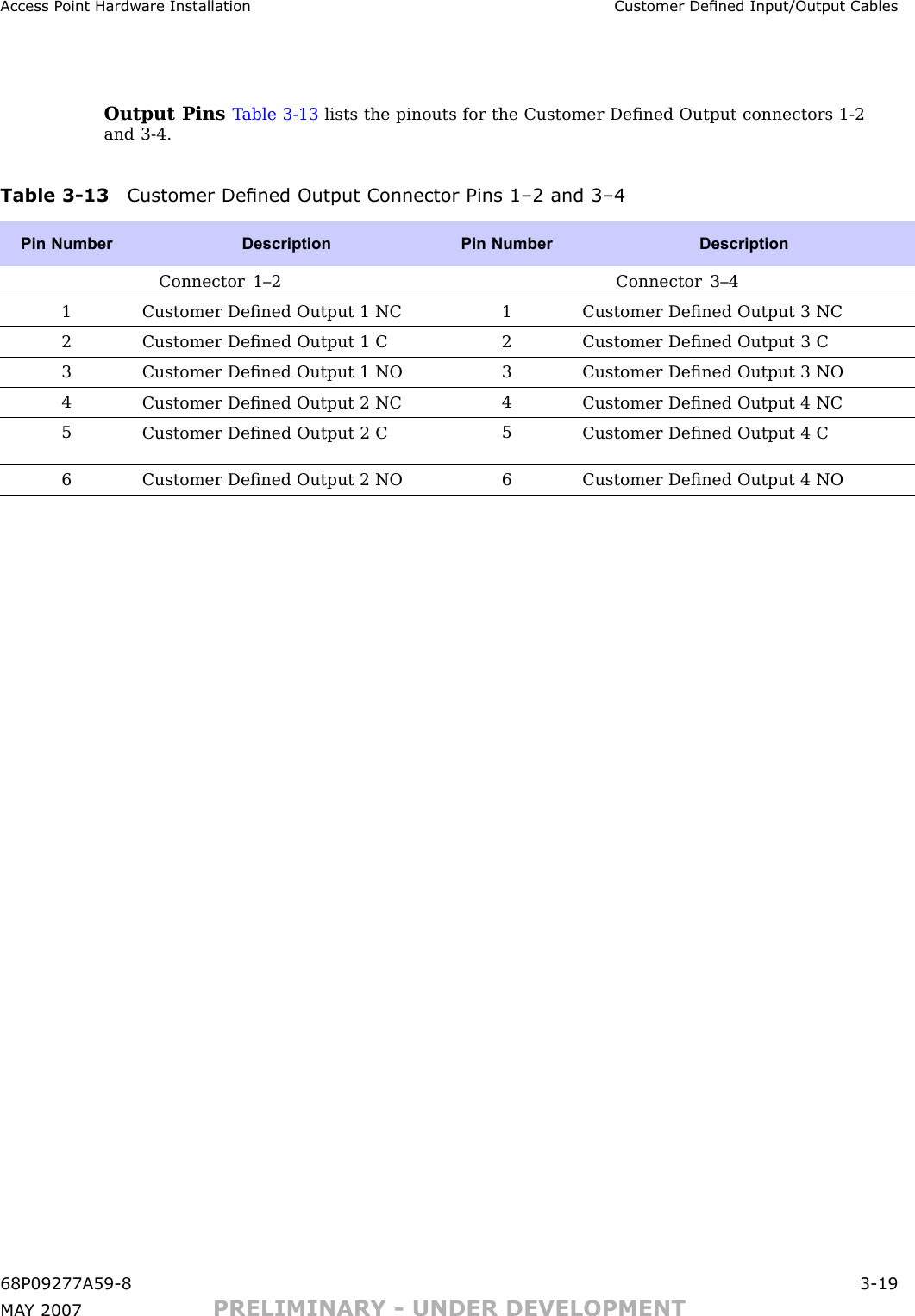
Access P oint Hardw are Installation Customer Dened Input/Output CablesOutput Pins T able 3 -13 lists the pinouts for the Customer Defined Output connectors 1 -2and 3 -4.Table 3 -13 Customer Dened Output Connector Pins 1–2 and 3–4Pin Number Description Pin Number DescriptionConnector 1–2 Connector 3–41Customer Defined Output 1 NC1Customer Defined Output 3 NC2Customer Defined Output 1 C2Customer Defined Output 3 C3Customer Defined Output 1 NO3Customer Defined Output 3 NO4Customer Defined Output 2 NC4Customer Defined Output 4 NC5Customer Defined Output 2 C5Customer Defined Output 4 C6Customer Defined Output 2 NO6Customer Defined Output 4 NO68P09277A59 -8 3 -19MA Y 2007 PRELIMINARY - UNDER DEVELOPMENT
Customer Dened Input/Output Cables Chapter 3: Cable Descriptions3 -20 68P09277A59 -8PRELIMINARY - UNDER DEVELOPMENT MA Y 2007
C h a p t e r4Access Point Hardware Installation■■■■■■■■■■■■■■■■■■■■■■■■■■■■■■■■■■■■■■■■■■■■■■■■■■■■■■■■■■■■■■■■■■68P09277A59 -8 4 -1MA Y 2007 PRELIMINARY - UNDER DEVELOPMENT
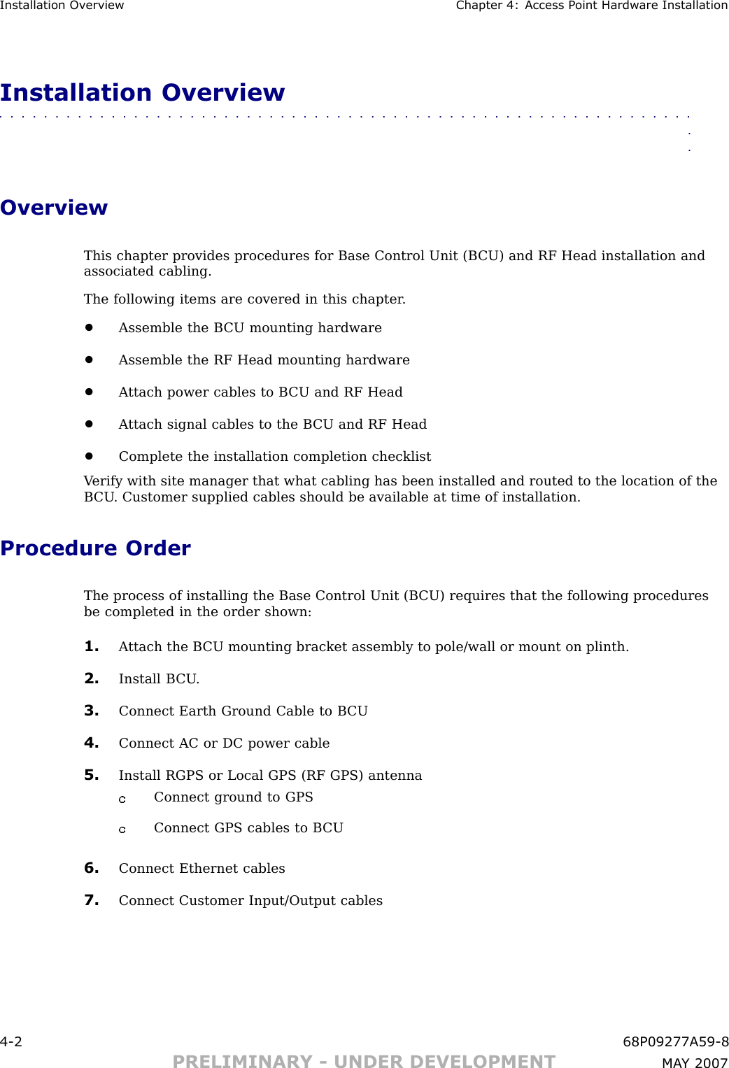
Installation Ov erview Chapter 4: Access P oint Hardw are InstallationInstallation Overview■■■■■■■■■■■■■■■■■■■■■■■■■■■■■■■■■■■■■■■■■■■■■■■■■■■■■■■■■■■■■■■■OverviewThis chapter provides procedures for Base Control Unit (B CU) and RF Head installation andassociated cabling.The following items are covered in this chapter .•Assemble the B CU mounting hardware•Assemble the RF Head mounting hardware•A ttach power cables to B CU and RF Head•A ttach signal cables to the B CU and RF Head•Complete the installation completion checklistV erify with site manager that what cabling has been installed and routed to the location of theB CU . Customer supplied cables should be available at time of installation.Procedure OrderThe process of installing the Base Control Unit (B CU) requires that the following proceduresbe completed in the order shown:1. A ttach the B CU mounting bracket assembly to pole/wall or mount on plinth.2. Install B CU .3. Connect Earth Ground Cable to B CU4. Connect AC or DC power cable5. Install RGPS or Local GPS (RF GPS) antennaConnect ground to GPSConnect GPS cables to B CU6. Connect Ethernet cables7. Connect Customer Input/Output cables4 -2 68P09277A59 -8PRELIMINARY - UNDER DEVELOPMENT MA Y 2007
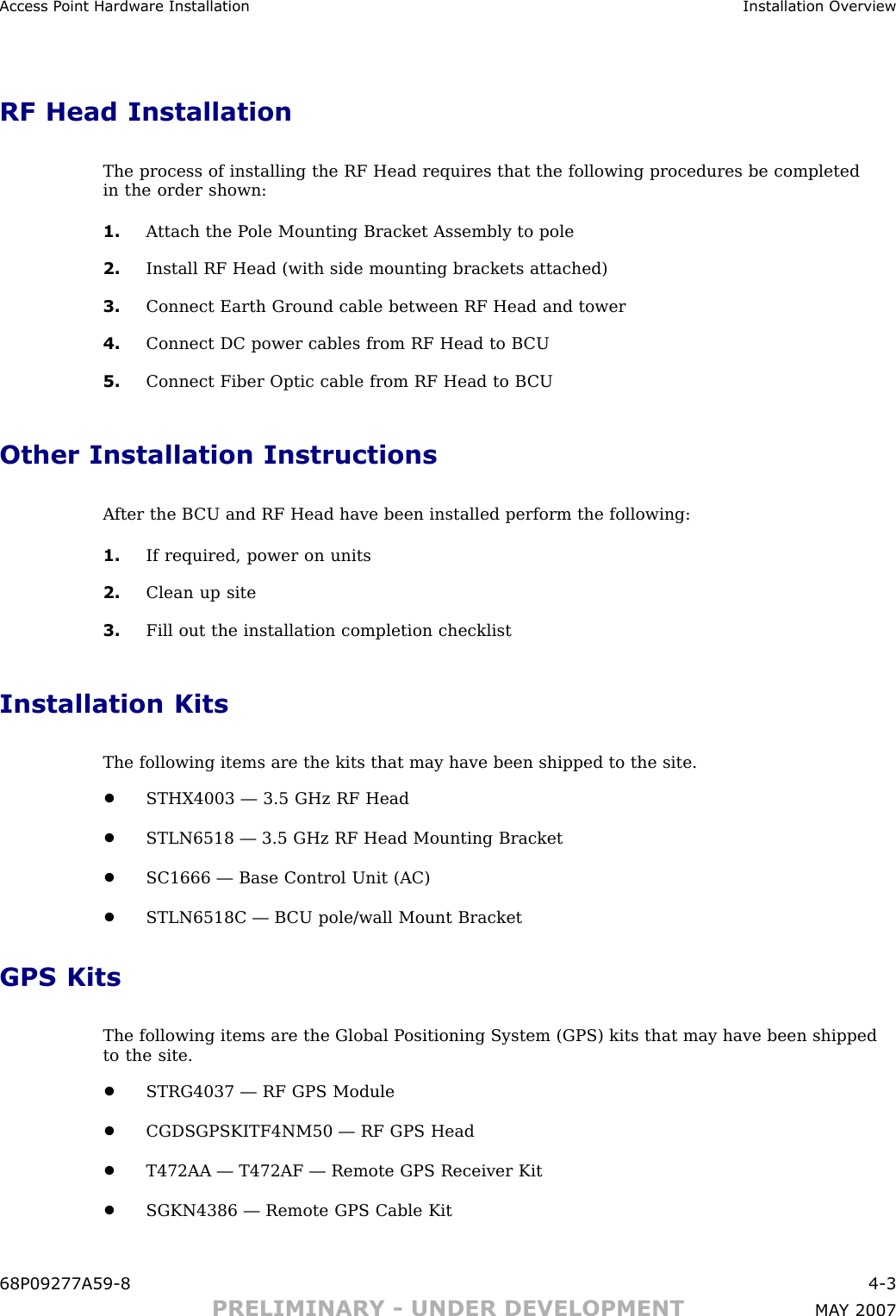
Access P oint Hardw are Installation Installation Ov erviewRF Head InstallationThe process of installing the RF Head requires that the following procedures be completedin the order shown:1. A ttach the P ole Mounting Bracket Assembly to pole2. Install RF Head (with side mounting brackets attached)3. Connect Earth Ground cable between RF Head and tower4. Connect DC power cables from RF Head to B CU5. Connect Fiber Optic cable from RF Head to B CUOther Installation InstructionsA fter the B CU and RF Head have been installed perform the following:1. If required, power on units2. Clean up site3. Fill out the installation completion checklistInstallation KitsThe following items are the kits that may have been shipped to the site.•STHX4003 — 3.5 GHz RF Head•STLN6518 — 3.5 GHz RF Head Mounting Bracket•SC1666 — Base Control Unit (AC)•STLN6518C — B CU pole/wall Mount BracketGPS KitsThe following items are the Global P ositioning System (GPS) kits that may have been shippedto the site.•STRG4037 — RF GPS Module•CGDSGPSKITF4NM50 — RF GPS Head•T472AA — T472AF — Remote GPS Receiver Kit•SGKN4386 — Remote GPS Cable Kit68P09277A59 -8 4 -3PRELIMINARY - UNDER DEVELOPMENT MA Y 2007
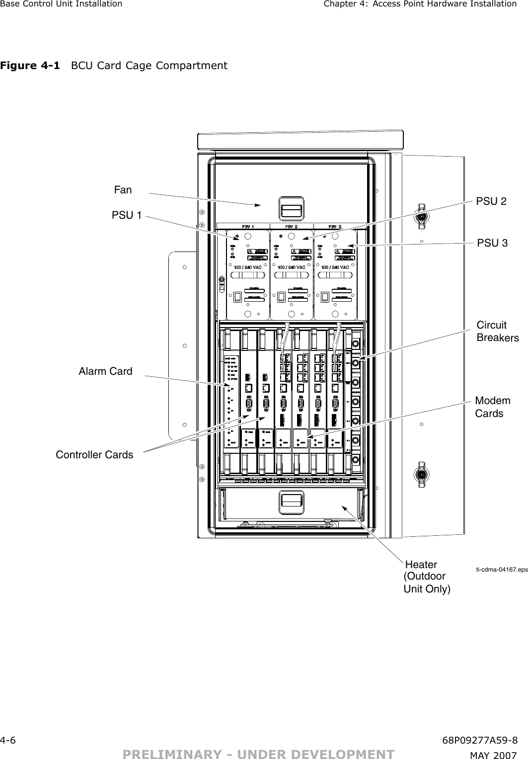
Connector Locations Chapter 4: Access P oint Hardw are InstallationConnector Locations■■■■■■■■■■■■■■■■■■■■■■■■■■■■■■■■■■■■■■■■■■■■■■■■■■■■■■■■■■■■■■■■Base Control Unit Connector LocationsFigure 4 -1 shows the location of the cable connectors on the B CU .RF Head Connector LocationsRefer to Figure 1 -4 for the location of the cable connectors on the RF Head.4 -4 68P09277A59 -8PRELIMINARY - UNDER DEVELOPMENT MA Y 2007
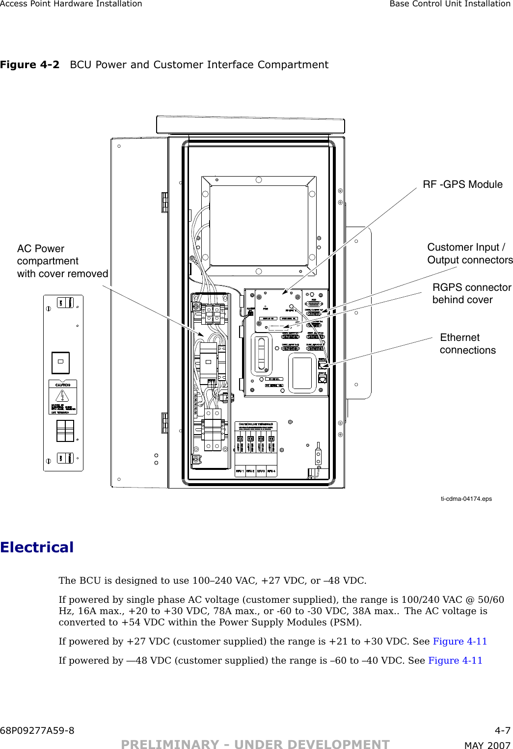
Access P oint Hardw are Installation Base Control Unit InstallationBase Control Unit Installation■■■■■■■■■■■■■■■■■■■■■■■■■■■■■■■■■■■■■■■■■■■■■■■■■■■■■■■■■■■■■■■■OverviewThis section contains procedures for installing a Base Control Unit (B CU). Refer to Figure 1 -1for an overall view of the B CU .BCU CompartmentsFigure 4 -1 and Figure 4 -2 show the two major compartments that make up the B CU .68P09277A59 -8 4 -5PRELIMINARY - UNDER DEVELOPMENT MA Y 2007
Base Control Unit Installation Chapter 4: Access P oint Hardw are InstallationFigure 4 -1 BCU Card Cage Compartmentti-cdma-04167.epsCircuit Breakers Modem CardsPSU 3Fan PSU 2PSU 1HeaterAlarm CardController Cards (OutdoorUnit Only)4 -6 68P09277A59 -8PRELIMINARY - UNDER DEVELOPMENT MA Y 2007
Access P oint Hardw are Installation Base Control Unit InstallationFigure 4 -2 BCU P ower and Customer Interface Compartmentti-cdma-04174.epsEthernet connectionsRGPS connectorbehind coverAC Powercompartment with cover removedCustomer Input /Output connectorsRF -GPS ModuleElectricalThe B CU is designed to use 100–240 V AC , +27 VDC , or –48 VDC .If powered by single phase AC voltage (customer supplied), the range is 100/240 V AC @ 50/60Hz, 16A max., +20 to +30 VDC , 78A max., or -60 to -30 VDC , 38A max.. The AC voltage isconverted to +54 VDC within the P ower Supply Modules (PSM).If powered by +27 VDC (customer supplied) the range is +21 to +30 VDC . See Figure 4 -11If powered by —48 VDC (customer supplied) the range is –60 to –40 VDC . See Figure 4 -1168P09277A59 -8 4 -7PRELIMINARY - UNDER DEVELOPMENT MA Y 2007
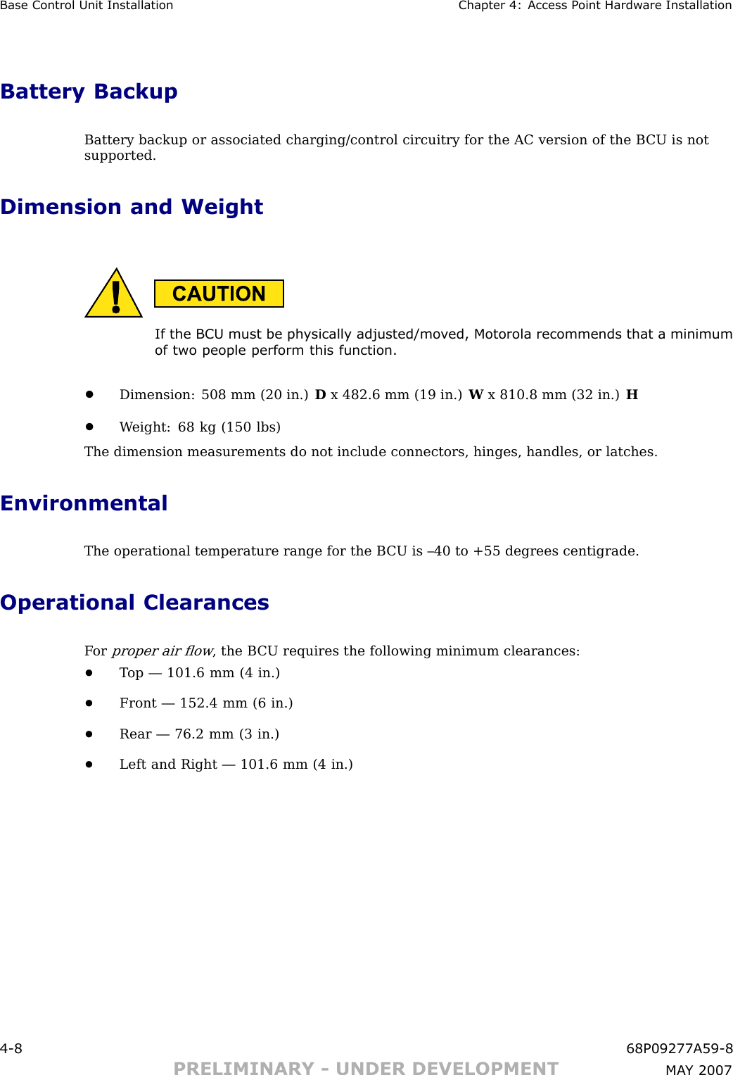
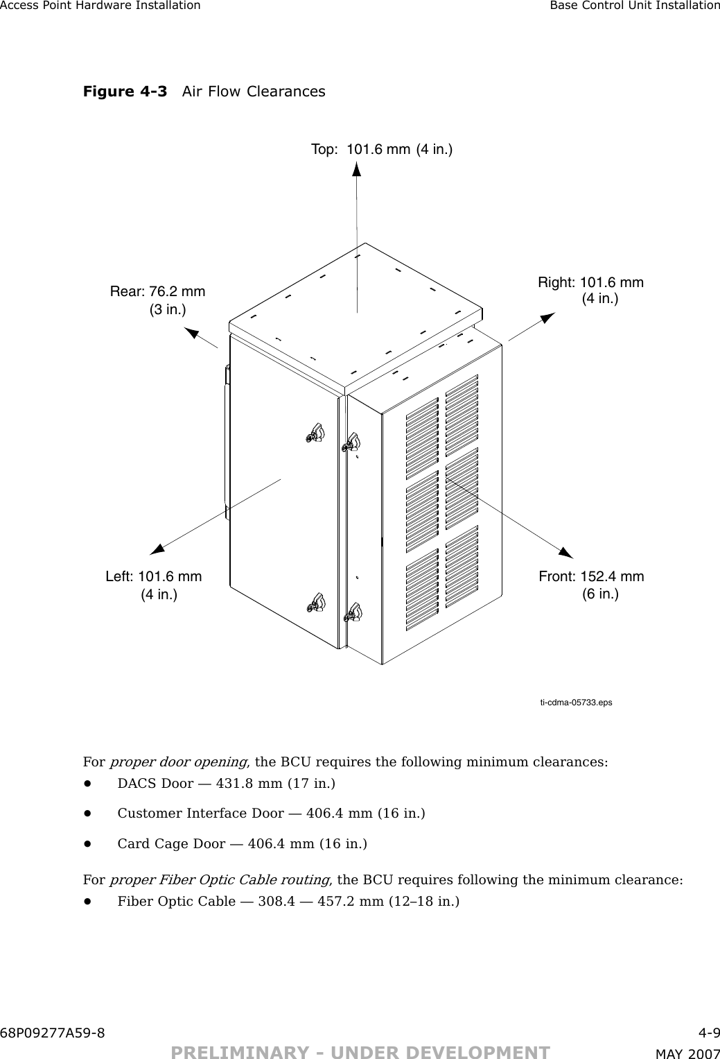
Base Control Unit Installation Chapter 4: Access P oint Hardw are InstallationBattery BackupBattery backup or associated charging/control circuitry for the AC version of the B CU is notsupported.Dimension and WeightIf the BCU must be ph ysically adjusted/mo v ed, Motorola recommends that a minimumof two people perform this function.•Dimension: 508 mm (20 in.) Dx 482.6 mm (19 in.) Wx 810.8 mm (32 in.) H•W eight: 68 kg (150 lbs)The dimension measurements do not include connectors, hinges, handles, or latches.EnvironmentalThe operational temperature range for the B CU is –40 to +55 degrees centigrade.Operational ClearancesF orproper air flow, the B CU requires the following minimum clearances:•T op — 101.6 mm (4 in.)•Front — 152.4 mm (6 in.)•Rear — 76.2 mm (3 in.)•Left and Right — 101.6 mm (4 in.)4 -8 68P09277A59 -8PRELIMINARY - UNDER DEVELOPMENT MA Y 2007
Access P oint Hardw are Installation Base Control Unit InstallationFigure 4 -3 Air Flow Clear ancesti-cdma-05733.epsTop:  101.6 mmRear: 76.2 mmFront: 152.4 mmLeft: 101.6 mm(4 in.)(4 in.)(4 in.)(3 in.)Right: 101.6 mm(6 in.)F orproper door opening, the B CU requires the following minimum clearances:•DACS Door — 431.8 mm (17 in.)•Customer Interface Door — 406.4 mm (16 in.)•Card Cage Door — 406.4 mm (16 in.)F orproper Fiber Optic Cable routing, the B CU requires following the minimum clearance:•Fiber Optic Cable — 308.4 — 457.2 mm (12–18 in.)68P09277A59 -8 4 -9PRELIMINARY - UNDER DEVELOPMENT MA Y 2007

Navigation menu