Nokia Solutions and Networks WTFA-01 GSM 800 Transciever User Manual dn9913495x3x0xen
Nokia Solutions and Networks GSM 800 Transciever dn9913495x3x0xen
Contents
Maintenance

Nokia MetroSite EDGE Base Station
DN9913495 © Nokia Corporation Draft 1 (52)
Issue 3-0 en Nokia Proprietary and Confidential
Maintenance

Maintenance
2 (52) © Nokia Corporation Draft DN9913495
Nokia Proprietary and Confidential Issue 3-0 en
The information in this documentation is subject to change without notice and describes only
the product defined in the introduction of this documentation. This documentation is intended
for the use of Nokia's customers only for the purposes of the agreement under which the
documentation is submitted, and no part of it may be reproduced or transmitted in any form or
means without the prior written permission of Nokia. The documentation has been prepared to
be used by professional and properly trained personnel, and the customer assumes full
responsibility when using it. Nokia welcomes customer comments as part of the process of
continuous development and improvement of the documentation.
The information or statements given in this documentation concerning the suitability, capacity,
or performance of the mentioned hardware or software products cannot be considered binding
but shall be defined in the agreement made between Nokia and the customer. However, Nokia
has made all reasonable efforts to ensure that the instructions contained in the documentation
are adequate and free of material errors and omissions. Nokia will, if necessary, explain issues
which may not be covered by the documentation.
Nokia's liability for any errors in the documentation is limited to the documentary correction of
errors. NOKIA WILL NOT BE RESPONSIBLE IN ANY EVENT FOR ERRORS IN THIS
DOCUMENTATION OR FOR ANY DAMAGES, INCIDENTAL OR CONSEQUENTIAL
(INCLUDING MONETARY LOSSES), that might arise from the use of this documentation or
the information in it.
This documentation and the product it describes are considered protected by copyright
according to the applicable laws.
NOKIA logo is a registered trademark of Nokia Corporation.
Other product names mentioned in this documentation may be trademarks of their respective
companies, and they are mentioned for identification purposes only.
Copyright © Nokia Corporation 2002. All rights reserved.
DN9913495 © Nokia Corporation Draft 3 (52)
Issue 3-0 en Nokia Proprietary and Confidential
Hereby, Nokia Corporation, declares that this product is in compliance with the
essential requirements and other relevant provisions of Directive: 1999/5/EC.
The product is marked with the CE marking and Notified Body number according to the
Directive 1999/5/EC.
FCC FCC §15.21 - Information to user - This product is used as an intentional radiated
equipment and any changes or modifications on the equipment without any approval
by Nokia could void the user's authority to operate the equipment.
FCC §15.105 - Information to user - This equipment has been tested and found to
comply with the limits for a Class B digital device, pursuant to part 15 of the FCC
Rules. These limits are designed to provide reasonable protection against harmful
interference in a residential installation. This equipment generates, uses and can
radiate radio frequency energy and, if not installed and used in accordance with the
instructions, may cause harmful interference to radio communications. However, there
is no guarantee that interference will not occur in a particular installation. If this
equipment does cause harmful interference to radio or television reception, which can
be determined by turning the equipment off and on, the user is encouraged to try to
correct the interference by one or more of the following measures:
• Reorient or relocate the receiving antenna.
• Increase the separation between the equipment and receiver.
• Connect the equipment into an outlet on a circuit different from that to which the
receiver is connected.
• Consult the dealer or an experienced radio/TV technician for help.
0523

Maintenance
4 (52) © Nokia Corporation Draft DN9913495
Nokia Proprietary and Confidential Issue 3-0 en

DN9913495 © Nokia Corporation Draft 5 (52)
Issue 3-0 en Nokia Proprietary and Confidential
Contents
Contents 5
List of tables 7
List of figures 8
1 About this document 11
2 Preparations for maintenance 13
2.1 Site folder 13
2.1.1 Fault reporting 13
2.2 Maintenance equipment 13
2.2.1 Nokia BTS Manager 14
2.3 Environmental precautions 14
2.4 Power supply precautions 14
2.5 Removing the BTS cover 15
3 Periodic maintenance 17
3.1 Maintaining the cabinet 17
3.1.1 Fan unit and air circulation 17
3.1.2 Cover 17
3.1.3 Seals 18
3.1.4 Lock 18
3.2 Periodic testing of the BTS 18
4 Adjusting the 13 MHz clock 19
5 Troubleshooting 23
5.1 Testing the BTS 23
5.2 Troubleshooting checklist 24
6 Replacing units 27
6.1 ESD protection 27
6.2 Removing units 28
6.3 Recycling of units 30
6.4 Replacing TRXs 30
6.4.1 TRX slot identification 30
6.4.2 Replacing a slave TRX 31
6.4.3 Replacing the master TRX in BTS configurations with two or more
TRXs 33
6.4.4 Replacing the master TRX in a single TRX BTS 34
6.5 Replacing the transmission unit 35
6.6 Replacing the interface unit 38
6.7 Replacing the power supply unit 39
6.8 Replacing the cooling fan 40
6.8.1 Replacing the HVMF cooling fan, version 1 40
6.8.2 Replacing the HVMF cooling fan, version 2 44


DN9913495 © Nokia Corporation Draft 7 (52)
Issue 3-0 en Nokia Proprietary and Confidential
List of tables
Table 1. Power supply rules during maintenance procedures 15
Table 2. Troubleshooting checklist 24
Table 3. LED conditions for TRX units 47
Table 4. LED conditions for a transmission unit 48
Table 5. LED conditions for an RRI transmission unit’s Flexbus LED. 48
Table 6. LED conditions for an interface unit 49
Table 7. LED conditions of the power supply unit 49
Table 8. LED conditions for the fan unit 50

Maintenance
8 (52) © Nokia Corporation Draft DN9913495
Nokia Proprietary and Confidential Issue 3-0 en
List of figures
Figure 1. Safety strap on the MetroSite EDGE BTS cover 16
Figure 2. 13 MHz clock adjustment 20
Figure 3. Clock control window - coarse adjustment 21
Figure 4. Fine adjustment of the DAC value 22
Figure 5. Electro-static sensitive device symbol 27
Figure 6. Connecting the antistatic wrist strap. 28
Figure 7. Removing the units 29
Figure 8. TRX slot numbering 31
Figure 9. Example Object Properties window in Nokia BTS Manager (can be used
for blocking a TRX) 32
Figure 10. Displacing the sealing strip and releasing the cables 41
Figure 11. HVMF cooling fan assembly and mounting screws 42
Figure 12. HVMF fan assembly, version 1 43
Figure 13. HVMF fan assembly, version 2 45
DN9913495 © Nokia Corporation Draft 9 (52)
Issue 3-0 en Nokia Proprietary and Confidential
Summary of changes
Version 1, 12th November 1999.
Version 2, 22nd June 2000:
• Added GSM to title and body text
• Added high capacity fan assembly (Figure 5)
• Added 13 MHz clock adjustment procedure
Version 3, 30th June 2001:
• Updated for EDGE
• Added power supply rules, new fan controller module, BTS chaining
• Improved 13 MHz clock adjustment illustration
• Harmonised style
Version 3, July 2002:
• Note added to 13 MHz clock adjustment chapter that a high stability
frequency counter is required.
Version 3, October 2002:
• BTS Manager 3.0 commands added for replacing transmission unit.

Maintenance
10 (52) © Nokia Corporation Draft DN9913495
Nokia Proprietary and Confidential Issue 3-0 en

About this document
DN9913495 © Nokia Corporation Draft 11 (52)
Issue 3-0 en Nokia Proprietary and Confidential
1About this document
This document gives instructions on the maintenance of the Nokia MetroSiteTM
EDGE Base Station (BTS). Read carefully Nokia MetroSite EDGE Base Station:
Warnings and Cautions before starting the maintenance work.
This document covers the following:
• preparations for maintenance
• periodic maintenance measures
• 13 MHz clock adjustment
• troubleshooting
• replacing units
• LED conditions of the MetroSite EDGE BTS units
Refer to the specific software release documentation for software updating
instructions.

Maintenance
12 (52) © Nokia Corporation Draft DN9913495
Nokia Proprietary and Confidential Issue 3-0 en

Preparations for maintenance
DN9913495 © Nokia Corporation Draft 13 (52)
Issue 3-0 en Nokia Proprietary and Confidential
Note
2Preparations for maintenance
This chapter describes the issues that must be considered in the maintenance of
the Nokia MetroSite EDGE BTS.
2.1 Site folder
A site folder contains site-specific information required on the site. The site
folders include installation, commissioning, and integration check lists. The exact
contents of the site folders are defined by the customer.
It is the responsibility of the customer to maintain and archive site-specific
documents.
2.1.1 Fault reporting
Where possible, correct all damage, failures, and faults and report them to Nokia
using the Failure Report Form provided by Nokia Customer Services.
You can save the alarm information to a log file on your PC with Nokia BTS
Manager.
2.2 Maintenance equipment
Check which tools are needed for the type of maintenance being done. For
information on the tools required, refer to Nokia MetroSite EDGE Base Station:
Requirements for Installation and Operation.
Always take the BTS key, antistatic wrist strap, and Nokia BTS Manager laptop
PC and LMP cable with you for BTS maintenance operations.
Maintenance
14 (52) © Nokia Corporation Draft DN9913495
Nokia Proprietary and Confidential Issue 3-0 en
WARNING
2.2.1 Nokia BTS Manager
When replacing or adding units, Nokia BTS Manager software is used for local
management of the BTS. Instructions for running specific maintenance
operations with Nokia BTS Manager are included in the relevant sections of this
document.
For more general information on using Nokia BTS Manager, refer to Nokia
MetroSite EDGE Base Station: Commissioning.
2.3 Environmental precautions
When the cover of the Nokia MetroSite EDGE Base Station is removed to allow
for maintenance work, the following conditions must be considered:
1. Rain or snow must not be allowed to fall on the internal surfaces of the
equipment.
2. The cover must not be removed during conditions where dust can be blown
into the cabinet.
2.4 Power supply precautions
Potentially lethal voltages!
The BTS power must be switched OFF at the main disconnect device or
circuit breaker before starting maintenance work which involves the risk of
electric shocks.
When working inside the BTS cabinet, prevent injury to personnel or damage to
the BTS equipment by following the requirements presented in Table .
Preparations for maintenance
DN9913495 © Nokia Corporation Draft 15 (52)
Issue 3-0 en Nokia Proprietary and Confidential
Note
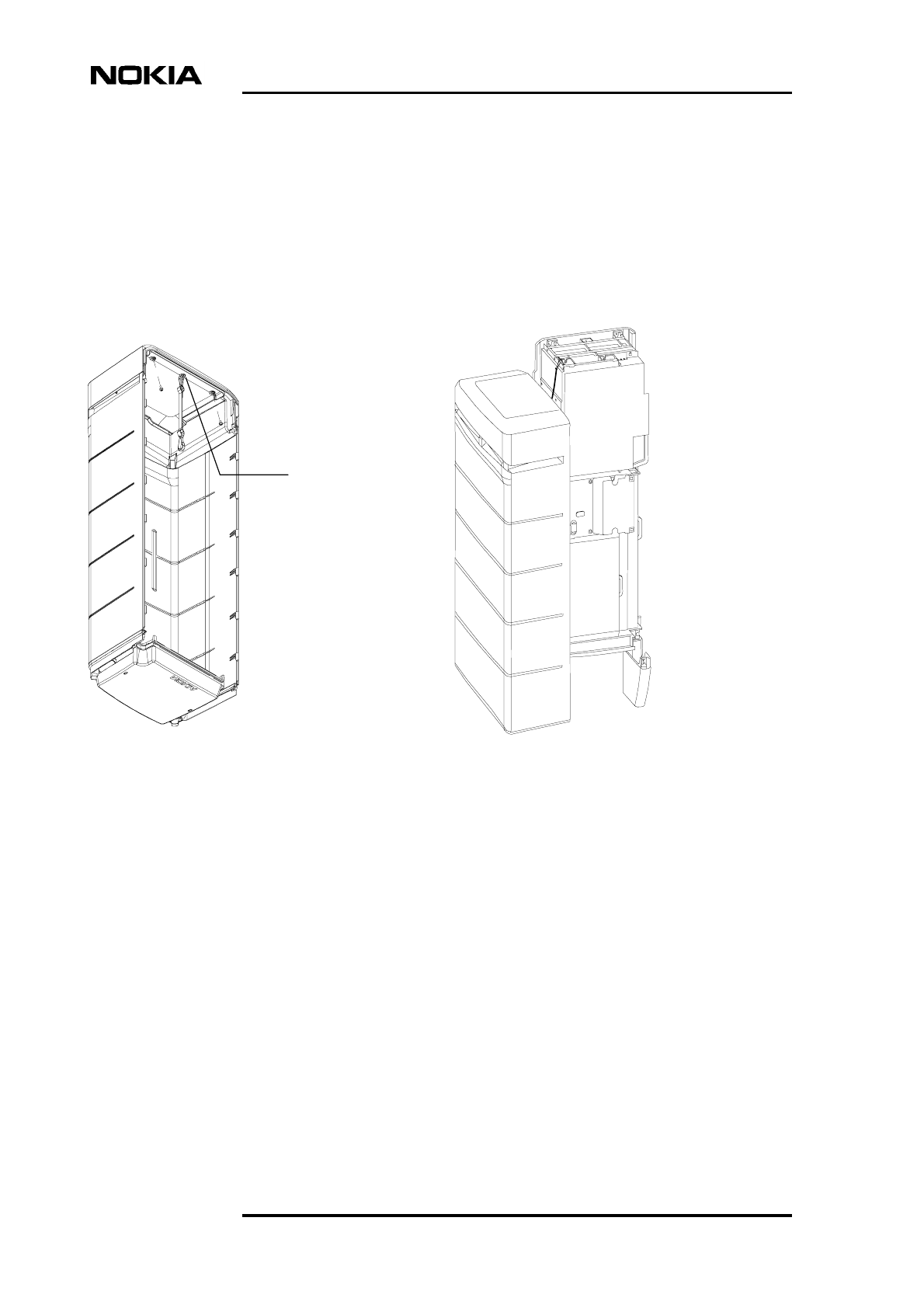
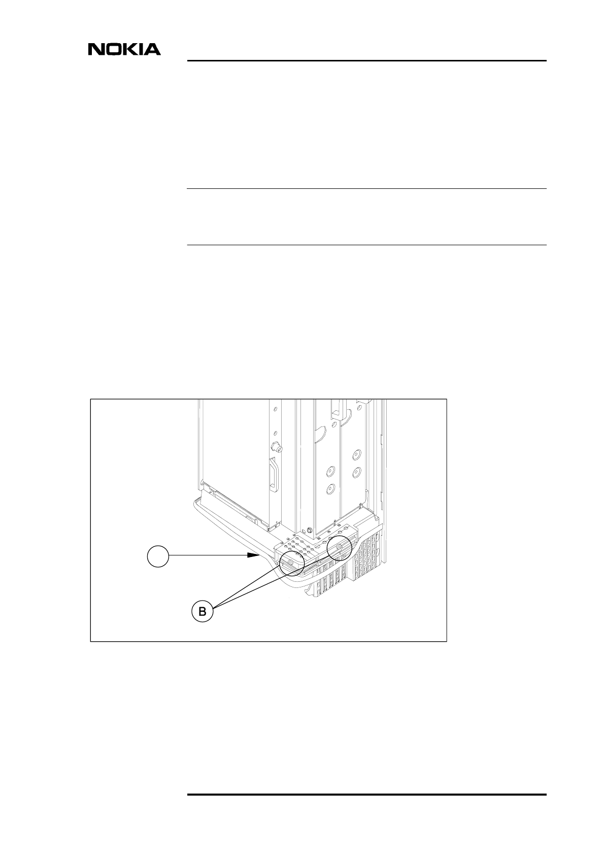
2.5 Removing the BTS cover
Before removing the cover for internal maintenance of the BTS, refer to the
power supply precautions and environmental restrictions presented in this
document and to the safety precautions presented in Nokia MetroSite EDGE Base
Station: Warnings and Cautions.
Removing the cover issues an alarm to the BSC. Make sure that the BSC/NMS
personnel is notified before removing the cover.
Removing the BTS cover
1. Unlock the cabinet lock at the bottom of the BTS.
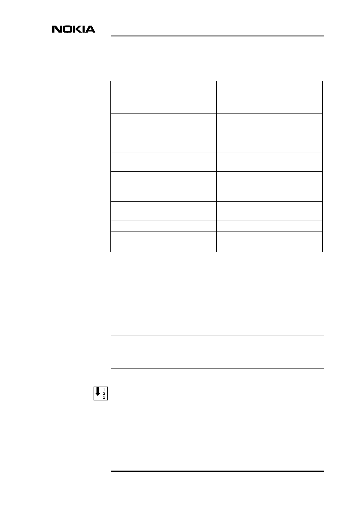
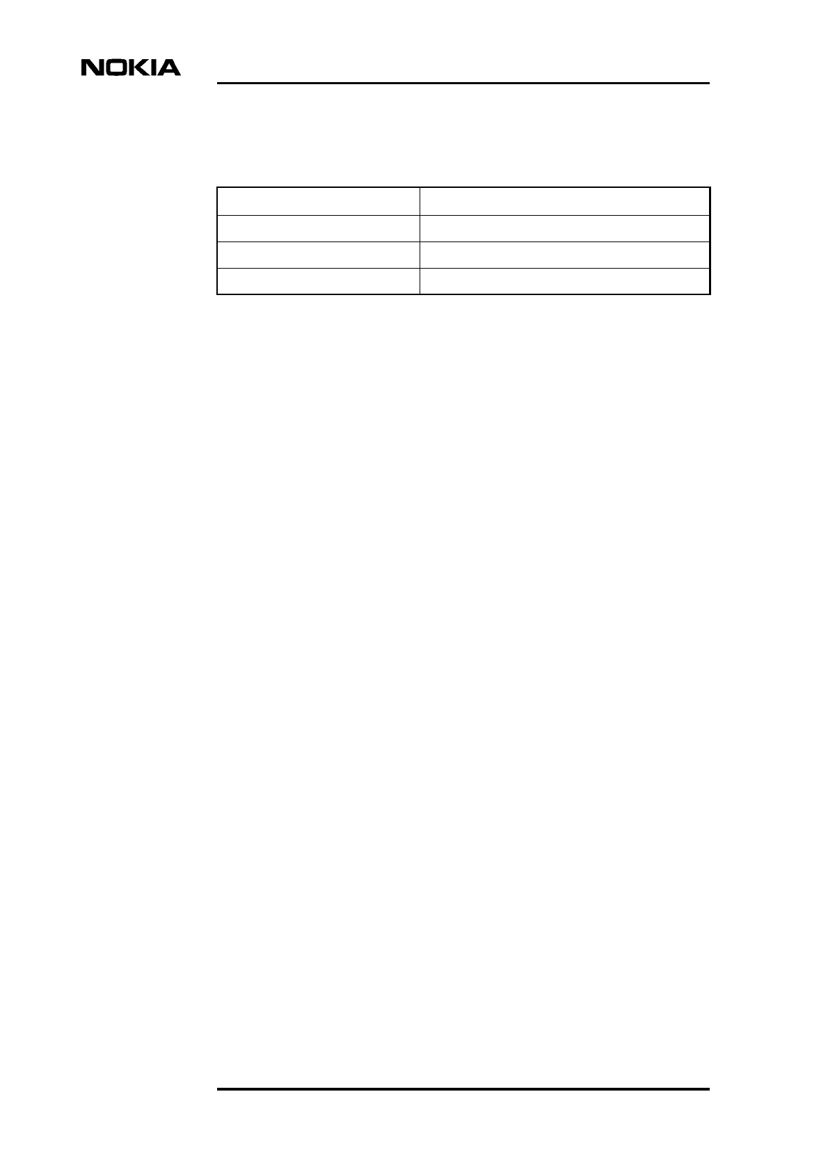
Table 1. Power supply rules during maintenance procedures
Procedure Power supply rule
Replacing a power supply unit or PSU
cable
Power OFF at main disconnect device
PSU switch to Stand-by
Replacing a grounding connection Power OFF at main disconnect device
PSU switch to Stand-by
Disconnecting or connecting antenna or
diversity cables on a TRX
PSU can be switched to ON but TRX
must be blocked
Replacing a TRX PSU can be switched to ON but TRX
must be blocked
Disconnecting or connecting
transmission cables
PSU can be switched to ON but TRX
must be blocked
Replacing a transmission unit PSU switch to Stand-by
Connecting or disconnecting cables to
the interface unit (VIFA)
PSU switch to Stand-by is advised
Replacing an interface unit PSU switch to Stand-by
Replacing a fan unit Power OFF at main disconnect device
PSU switch to Stand-by
Maintenance
16 (52) © Nokia Corporation Draft DN9913495
Nokia Proprietary and Confidential Issue 3-0 en
2. Remove the cover by sliding it upwards to disengage the hooks at the side
of the cover from the locking guides on the BTS chassis.
3. When the cover is free, pull it away from the cabinet and hang it on the
hook at the top left side of the chassis.
You can also remove the cover completely to place it on the floor. Remove
the safety strap before pulling the cover away (see Figure 1).
Figure 1. Safety strap on the MetroSite EDGE BTS cover
Fixing point
for safety strap
under the
cover top
Periodic maintenance
DN9913495 © Nokia Corporation Draft 17 (52)
Issue 3-0 en Nokia Proprietary and Confidential
Caution
Caution
3Periodic maintenance
This chapter describes the periodic maintenance of the MetroSite EDGE Base
Station.
3.1 Maintaining the cabinet
This section describes the cabinet maintenance measures.
3.1.1 Fan unit and air circulation
The fan unit must be cleaned of leaves and debris whenever necessary. To
maintain proper circulation of air through the cabinet, air inlets and outlets must
not be obstructed.
3.1.2 Cover
Clean the BTS cover of stains and dust whenever necessary. Wipe the surface of
the cover with a piece of cloth moistened with water and a washing agent.
Do not use any washing agents that contain alkalis, esters, ketones, or aromatic,
chlorinated, or fluorinated hydrocarbons, since these may damage the cover.
Washing agents containing these chemicals can only be used if approved by the
manufacturer for cleaning polycarbonate objects.
Do not spill any water or chemicals inside the cover.

Maintenance
18 (52) © Nokia Corporation Draft DN9913495
Nokia Proprietary and Confidential Issue 3-0 en
3.1.3 Seals
Wipe the BTS seals (seal on the lower edge of the BTS, under the cover)
whenever they are dirty. The cleaning interval depends on the environment.
Check the visible seals during every site visit. If the seals are dirty, wipe them
clean with a piece of cloth. Replace worn or broken seals.
3.1.4 Lock
Lubricate the lock during site visits with lubricating oil. If the cabinet is used in
temperatures below 0ºC (32ºF), lubricate the lock with lubricating anti-freeze oil
or use both anti-freeze oil and lubricating oil.
3.2 Periodic testing of the BTS
The condition of the hardware in the MetroSite EDGE BTS can be tested
periodically by running the Abis loop test and the TRX test remotely from the
BSC/NMS. A TRX test can also be run locally with Nokia BTS Manager.
Adjusting the 13 MHz clock
DN9913495 © Nokia Corporation Draft 19 (52)
Issue 3-0 en Nokia Proprietary and Confidential
Note
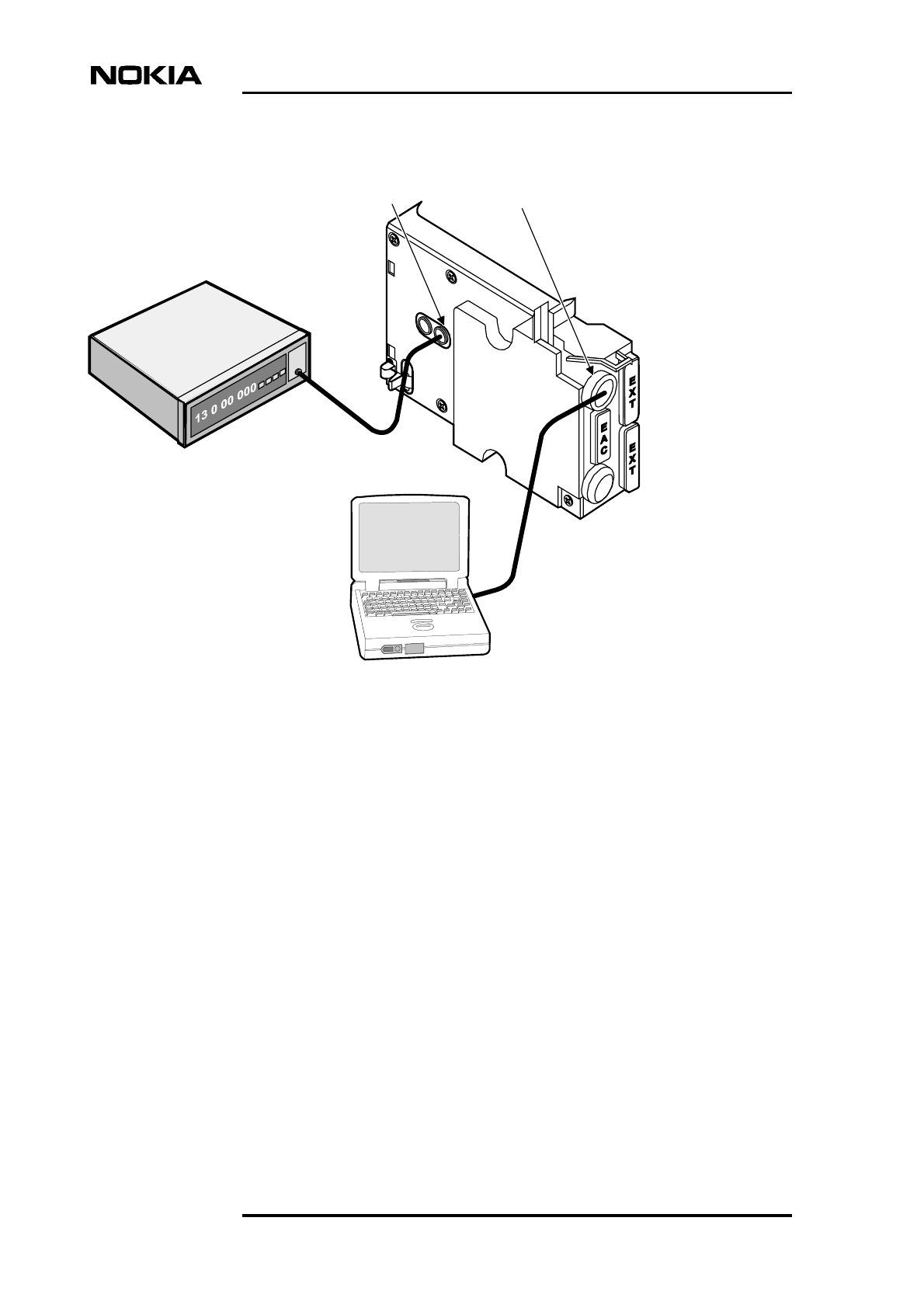
4Adjusting the 13 MHz clock
The 13 MHz clock is adjusted using the Nokia BTS Manager PC and a frequency
counter.
The 13 MHz clock should only need adjusting after a new installation or when the
interface unit (VIFA) is replaced.
Before commencing the adjustment procedure, switch ON the frequency counter
and allow for a stabilising time of about 15 minutes, or as recommended by the
instrument’s manufacturer.
Use only a high stability frequency counter for this procedure.
Adjusting the 13 MHz clock
1. Remove the rubber dust shield from the side of the interface unit.
2. Connect the frequency counter to the X7 connector on the interface unit
(first socket from the front). See Figure 2.
3. Connect the Nokia BTS Manager laptop PC to the LMP port of the
interface unit. See Figure 2.
Maintenance
20 (52) © Nokia Corporation Draft DN9913495
Nokia Proprietary and Confidential Issue 3-0 en
Figure 2. 13 MHz clock adjustment
4. Open Nokia BTS Manager on your laptop PC.
5. Open the calibration menu by selecting OBJECTS on the BTS Manager
main menu.
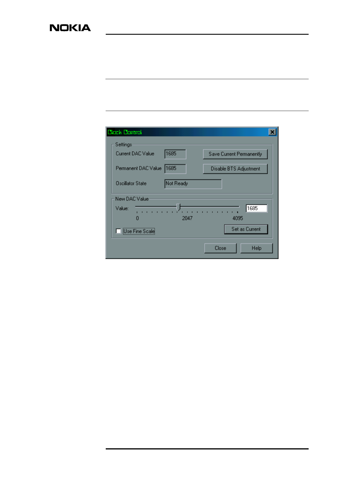
6. Select CLOCK CONTROL from the drop-down menu.
7. In the Clock Control window, enter a DAC (digital-to-analogue converter)
value which will tune the clock to 13 MHz (±1 Hz).
VIFA Unit
Frequency counter
Laptop fitted
with Nokia BTS
Manager
X7 LMP
Adjusting the 13 MHz clock
DN9913495 © Nokia Corporation Draft 21 (52)
Issue 3-0 en Nokia Proprietary and Confidential
Note
Change the DAC value with the slider or by typing the DAC value directly
in the box (see Figure 3).
To increase the frequency, increase the DAC value. The range of DAC values is
from 0 to 4095, providing an adjustment of ±25 Hz.
Figure 3. Clock control window - coarse adjustment
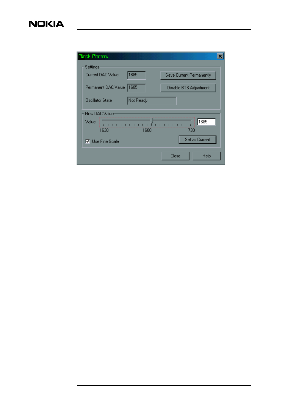
Fine adjustment of the DAC value slider is achieved by clicking the ‘Use
Fine Scale’ check box in the Clock Control window (see Figure 4).
Maintenance
22 (52) © Nokia Corporation Draft DN9913495
Nokia Proprietary and Confidential Issue 3-0 en
Figure 4. Fine adjustment of the DAC value
8. Save the DAC value by clicking the SAVE CURRENT PERMANENTLY
button in the Clock Control window. Click the CLOSE button or press
Enter on your keyboard.
Saving the DAC value permanently will ensure that it remains in the clock
memory after reset.
9. When asked if you want to continue, select YES in the dialogue box.
Troubleshooting
DN9913495 © Nokia Corporation Draft 23 (52)
Issue 3-0 en Nokia Proprietary and Confidential
Note
Note
5Troubleshooting
This chapter gives advice on how to identify and rectify possible faults in the
operation of the Nokia MetroSite EDGE Base Station.
Troubleshooting instructions related to BTS commissioning are given in Nokia
MetroSite EDGE Base Station: Commissioning.
Detailed descriptions of BTS alarms are presented in Nokia MetroSite EDGE
Base Station: Alarm Descriptions. Descriptions of the LED unit status indicators
are presented in Chapter 7 of this document.
Whenever problems occur in the operation of the BTS, connect the Nokia BTS
Manager PC to the interface unit. The LED conditions and the alarm window
usually indicate where and what the problem is. To obtain more information on
the BTS’s status, it is also advisable to be in contact with the BSC by mobile
phone (MS).
5.1 Testing the BTS
If there is any reason to assume that the quality of calls in a cell is degraded, or
that the number of calls in a cell is reduced, the Abis loop test and the TRX test
can be run remotely from the BSC/NMS. A TRX test can also be run locally with
Nokia BTS Manager.
Further troubleshooting tests can also be done locally at the BTS. See the
Troubleshooting checklist in Section 5.2 of this document and the LED indicator
conditions reference information in Chapter 7 of this document.
Maintenance
24 (52) © Nokia Corporation Draft DN9913495
Nokia Proprietary and Confidential Issue 3-0 en
5.2 Troubleshooting checklist
Table 2. Troubleshooting checklist
Symptom Possible fault Action
BTS is powered ON but
the BTS Manager
connection cannot be
established.
1. Master TRX broken. 1. Replace the master
TRX with one of the slave
TRXs and insert a new
TRX into the slave TRX’s
slot. Refer to Section
6.4.3.
2. Interface unit broken. 2. Replace the interface
unit.
3. Wrong BTS Manager
port setting (COM 1, COM
2).
3. Correct the COM port
settings.
4. LMP cable broken or
not properly connected.
4. Check the connection
before replacing the cable.
No power to the BTS. 1. Fault in the site mains
power supply.
1. Check the site’s mains
power source and fuses.
Replace if necessary.
2. Broken power cable. 2. Replace the cable.
3. Power supply unit
broken.
3. Replace the power
supply unit.
4. Short circuit in one of
the BTS units.
4. Pull the units out one by
one until the power comes
back on. Start from the
TRXs and proceed to the
transmission unit, fan unit
and finally to the interface
unit. Return the units one
by one and replace the
faulty unit(s).
5. Power supply unit
switch in stand-by
position.
5. Turn the PSU’s switch to
the ON position.
6. Cold start active. 6. Wait until the units have
warmed up to the
operational temperature
range and the power
supply unit LED turns
green.
Troubleshooting
DN9913495 © Nokia Corporation Draft 25 (52)
Issue 3-0 en Nokia Proprietary and Confidential
No transmission
connection to the BSC
(yellow or red LED on
transmission unit).
1. Abis cable not
connected or connected
incorrectly.
1. Check that the cable is
connected on the
transmission unit and at
the BSC. Check that the
RX and TX cables are
connected to the correct
connectors.
2. Abis cable broken. 2. Replace the cable.
3. Line interface broken. 3. Connect a jumper cable
from the TX connector of
each transmission
interface to its RX
connector. If the green
LED is lit the line interface
is OK. Otherwise, change
the transmission unit.
4. Transmission unit
broken
4. Replace the
transmission unit.
Transmission connection
works but there is a yellow
LED lit on the
transmission unit.
No real time connection
from the network to the
transmission unit.
Establish the BSC
connection.
The device status report
in the BTS Manager
indicates that the BCCH
TRX and a slave TRX are
in the ‘Supervisory’ state,
but the yellow LED blinks
on both TRXs.
Objects are locked from
the BSC/NMS.
Request the state from the
BSC/NMS. Request an
unlock from the BSC/NMS
if necessary.
Table 2. Troubleshooting checklist (Continued)
Symptom Possible fault Action

Maintenance
26 (52) © Nokia Corporation Draft DN9913495
Nokia Proprietary and Confidential Issue 3-0 en
Replacing units
DN9913495 © Nokia Corporation Draft 27 (52)
Issue 3-0 en Nokia Proprietary and Confidential
Caution
Caution
6Replacing units
This chapter describes how to replace plug-in units in the Nokia MetroSite EDGE
Base Station.
BSC and/or NMS personnel must be notified before starting to replace or add
units to the Nokia MetroSite EDGE Base Station.
6.1 ESD protection
Some units in the MetroSite BTS contain electro-static sensitive devices. The
BTS is labelled with an electro-static sensitive device symbol as shown in Figure
5.
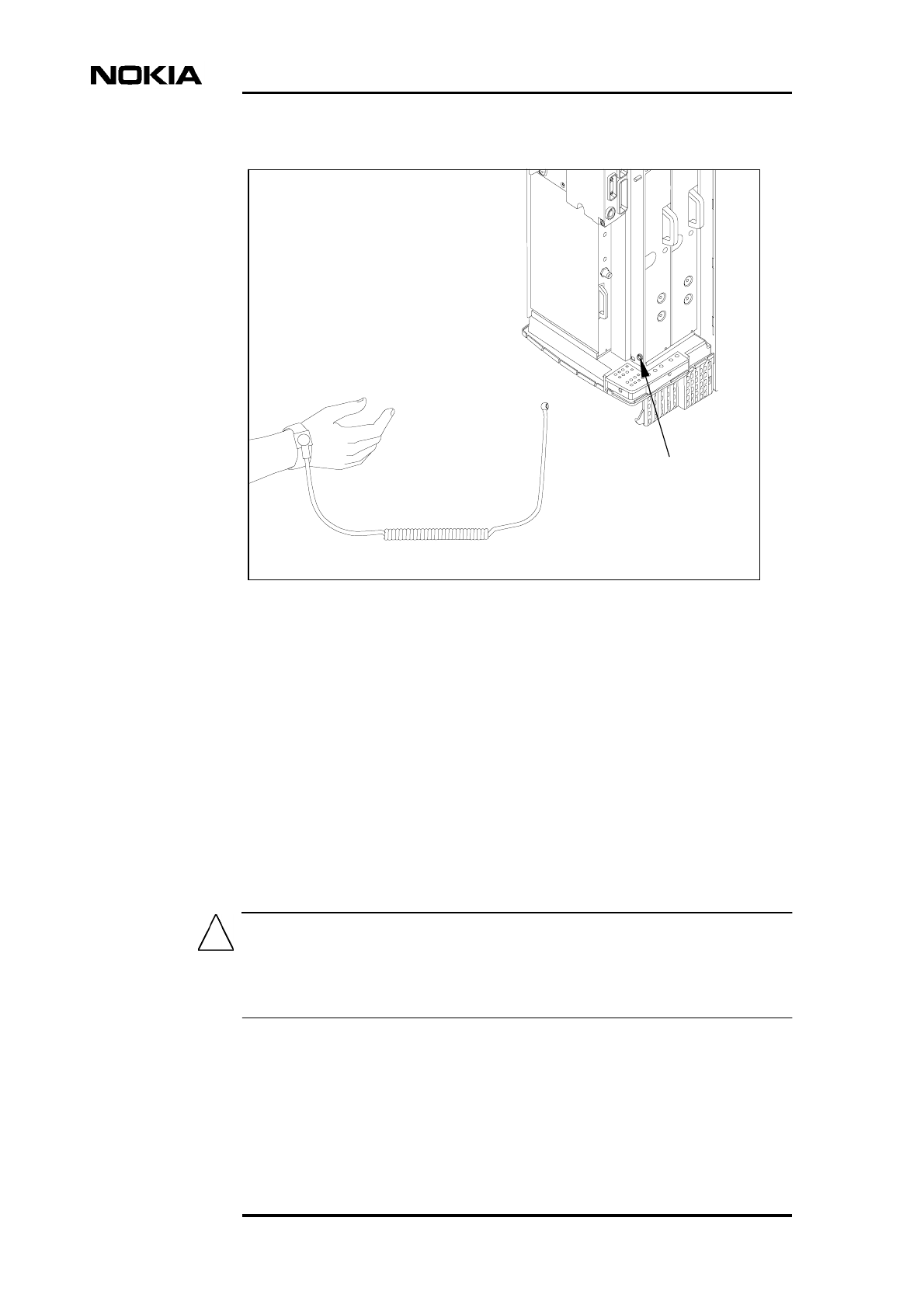
Always use an anti-static wrist strap connected to the cabinet ESD stud, whenever
handling electro-static sensitive units. The wrist strap and connection stud is
shown in Figure 6.
Figure 5. Electro-static sensitive device symbol
Maintenance
28 (52) © Nokia Corporation Draft DN9913495
Nokia Proprietary and Confidential Issue 3-0 en
Caution
Figure 6. Connecting the antistatic wrist strap.
6.2 Removing units
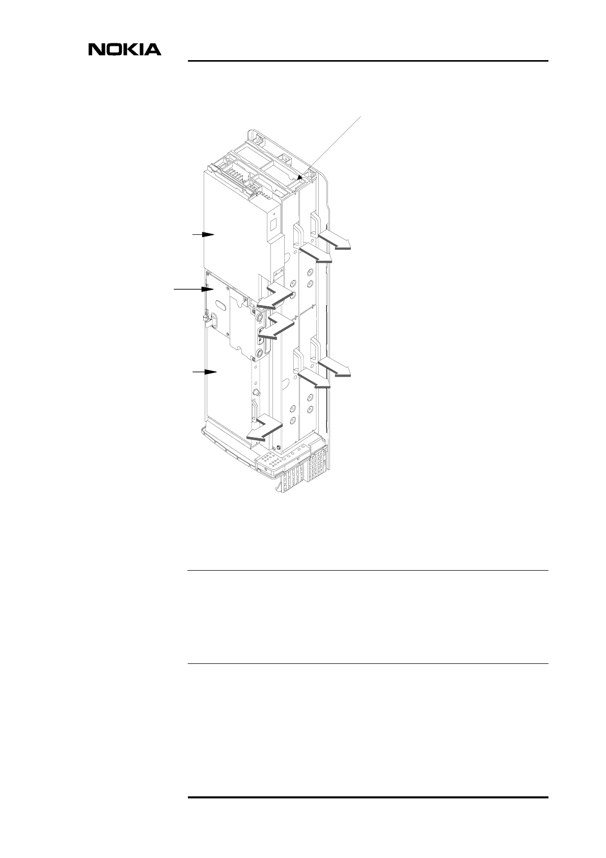
Figure 7 shows how the units are pulled out from the unit slots. Read the detailed
step instructions for each unit before pulling the units out.
If you are replacing BTS units, keep the units protected in their delivery packages
until they are needed. After installation, keep some of the packaging material for
packing the removed units when sending them for service. Recycle any remaining
packaging material.
Handle the units with care. Do not knock the units or place them with their
connectors facing the ground. Prevent dirt, water, or snow from entering the
connectors.
ESD stud
to ESD stud
Wrist strap
Replacing units
DN9913495 © Nokia Corporation Draft 29 (52)
Issue 3-0 en Nokia Proprietary and Confidential
Note
Figure 7. Removing the units
Examine the retaining screws when replacing units. If there are any traces of
aluminium burrs on the thread, replace the screw.
Spare counterparts for unit retaining screws can be found attached to the
uppermost TRX guide beam on the top of the BTS (see Figure 7).
Power supply unit
Interface unit
Transmission unit
Transceiver units
Spare counterparts
for unit retaining screws
Maintenance
30 (52) © Nokia Corporation Draft DN9913495
Nokia Proprietary and Confidential Issue 3-0 en
Note
The shield unit fixing screws may only be tightened to 1.0 Nm (0.74 lb ft). Use a
torque driver with a T10 Torx bit to tighten them.
6.3 Recycling of units
In case you need to dispose of the units or the whole BTS, contact Nokia
Professional Services for information on recycling. An environmental data
package, including disassembly instructions and a material balance document is
also available via Nokia Professional Services.
6.4 Replacing TRXs
This section provides instructions on how to replace faulty TRXs. There are three
different scenarios for replacing TRXs, as follows:
• replacing a slave TRX
• replacing the master TRX
• replacing the master TRX in a single TRX BTS
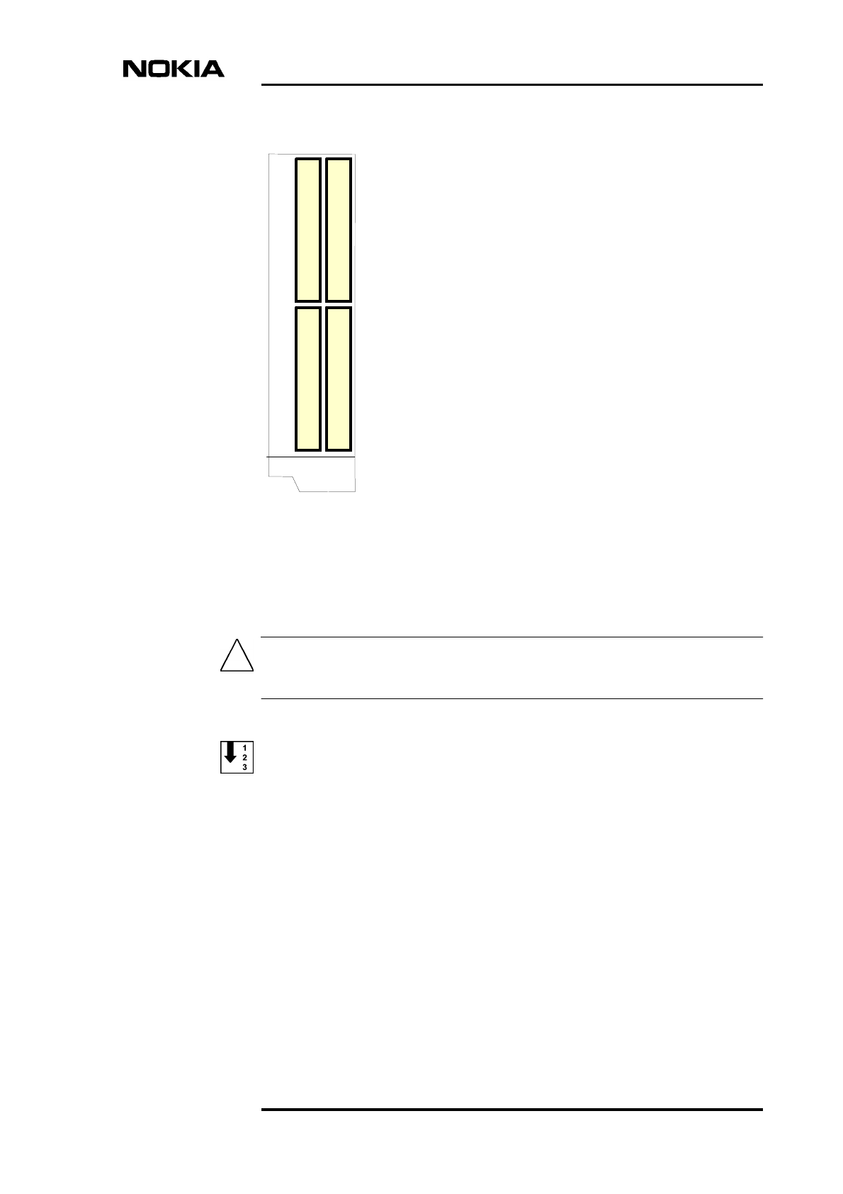
6.4.1 TRX slot identification
The TRX in slot 1 is the master TRX of the Nokia MetroSite EDGE Base Station.
Figure 8 shows the numbering order of the TRX slots.
Replacing units
DN9913495 © Nokia Corporation Draft 31 (52)
Issue 3-0 en Nokia Proprietary and Confidential
Caution
Figure 8. TRX slot numbering
6.4.2 Replacing a slave TRX
Make sure the TRX that you are replacing is a slave TRX (slots 2, 3, or 4).
Replacing a slave TRX
1. Connect your Nokia BTS Manager PC to the LMP connector on the
interface unit.
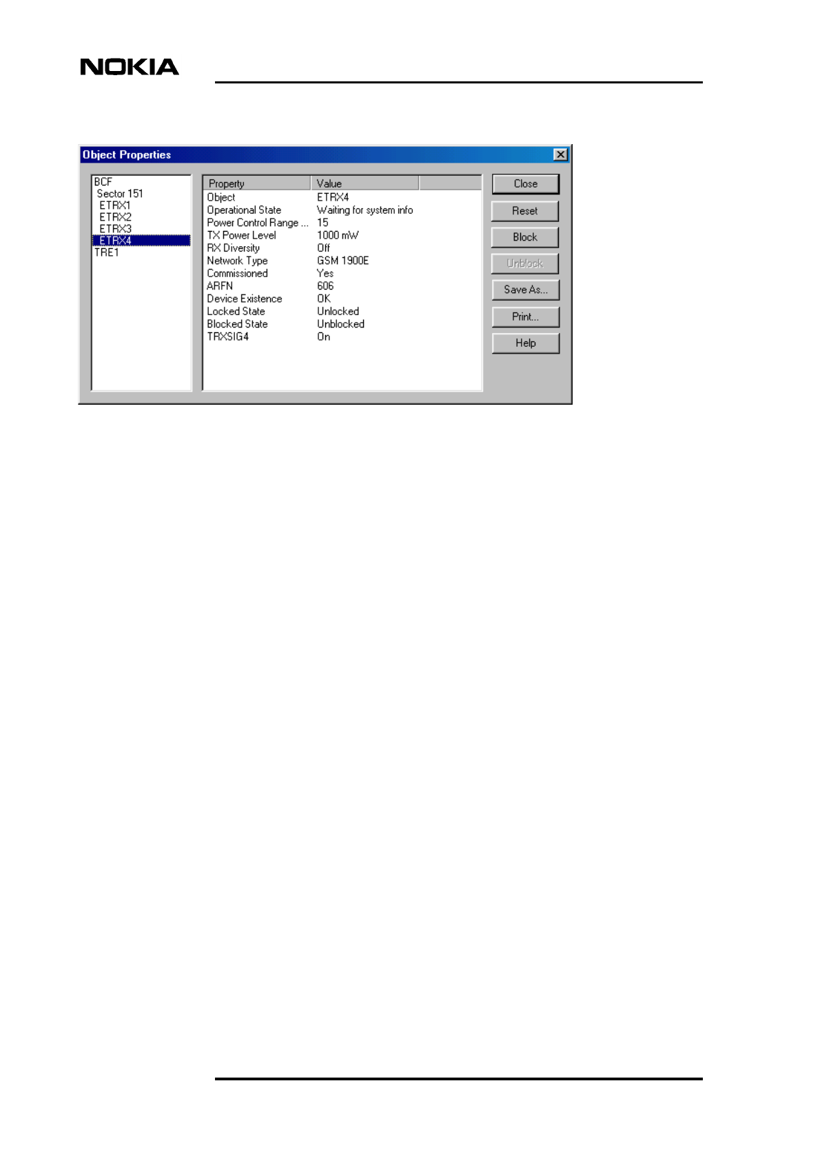
2. Block the TRX using Nokia BTS Manager (if the sector is not already
locked from the BSC). In the Supervision - Equipment View window, right
click on the TRX image and select the BLOCK button in the Object
Properties dialogue window (see Figure 9).
T
R
X
3
T
R
X
4
T
R
X
1
T
R
X
2
Maintenance
32 (52) © Nokia Corporation Draft DN9913495
Nokia Proprietary and Confidential Issue 3-0 en
Figure 9. Example Object Properties window in Nokia BTS Manager (can be
used for blocking a TRX)
3. Make a note of the TRX cabling.
4. Disconnect the TRX cabling.
5. Undo the retaining screws of the TRX unit with a T10 Torx driver. Loosen
the screws enough to remove the unit, but leave them engaged in the thread
to allow easy refitting.
6. Remove the TRX.
7. Unpack the new TRX.
8. Insert the TRX into the free slot.
9. Tighten the TRX retaining screws to 1.5 Nm (11.1 lb ft) with a T10 Torx
driver.
10. Reconnect the TRX cabling.
11. Run the TRX test from Nokia BTS Manager (optional).
12. With Nokia BTS Manager, right-click the BCF object in the Equipment
View window and carry out a BCF Object Reset, or, if locked from the
BSC/NMS, request an unlock from the BSC/NMS (the BCF reset is
automatic in this case).
If the green LED is lit on the TRX after the replacement procedure, the BTS is in
service. If the LED is yellow or red, check the alarms and run the TRX test from
the BSC/NMS.
Replacing units
DN9913495 © Nokia Corporation Draft 33 (52)
Issue 3-0 en Nokia Proprietary and Confidential
Note
6.4.3 Replacing the master TRX in BTS configurations with two or more
TRXs
If you want to run the TRX test locally, you must do this before unlocking the site.
If you want to run the TRX test remotely, you must do this after unlocking the
site.
Replacing the master TRX
1. Connect your Nokia BTS Manager PC to the LMP connector on the
interface unit.
2. Block the site locally (BCF Block) using Nokia BTS Manager if the site is
not already locked from the BSC/NMS.
3. Open the cable entry block.
4. Make a note of the TRX cabling.
5. Disconnect the cabling from the faulty master TRX.
6. Disconnect the cabling from one of the slave TRXs.
7. Open the master TRX retaining screws with Torx T10 driver. Loosen the
screws enough to remove the unit, but leave them engaged in the thread to
allow easy refitting.
8. Remove the master TRX.
9. Open the slave TRX retaining screws with a Torx T10 driver.
10. Remove the uncabled slave TRX.
11. Insert the removed slave TRX to the slot of the master TRX and tighten the
retaining screws with a Torx T10 driver.
12. Unpack a new TRX.
13. Insert the new TRX into the slot of the removed slave TRX and tighten the
retaining screws with a Torx T10 driver.
14. Re-cable the TRXs.
15. Close the cable entry block.
Maintenance
34 (52) © Nokia Corporation Draft DN9913495
Nokia Proprietary and Confidential Issue 3-0 en
16. With Nokia BTS Manager, right-click the BCF object in the Equipment
View window and carry out a BCF Object Reset, or, if locked from the
BSC/NMS, request an unlock from the BSC/NMS (the BCF reset is
automatic in this case).
If the green LED is lit on the TRX after the replacement procedure, the BTS is in
service. If the LED is yellow or red, check the alarms and run the TRX test from
the BSC/NMS.
6.4.4 Replacing the master TRX in a single TRX BTS
Replacing the master TRX in a single TRX BTS
1. Connect your Nokia BTS Manager PC to the LMP connector on the
interface unit.
2. Block the BCF locally with Nokia BTS Manager, or request a BCF lock
from the BSC/NMS.
3. If the manager connection can still be established, open Traffic Manager
from the Transmission menu and export the TS allocation information to
your PC’s hard disk.
4. Open the cable entry block.
5. Make a note of the TRX cabling.
6. Disconnect the TRX cabling.
7. Open the TRX retaining screws with a Torx T10 driver. Loosen the screws
enough to remove the unit, but leave them engaged in the threads to allow
easy refitting.
8. Remove the TRX.
9. Unpack a new TRX.
10. Insert the new uncommissioned TRX into the master TRX slot (slot 1).
11. Tighten the TRX retaining screws to 1.5 Nm (1.11 lb ft) with a Torx T10
driver.
12. Re-cable the TRX.
13. Close the cable entry block.
Replacing units
DN9913495 © Nokia Corporation Draft 35 (52)
Issue 3-0 en Nokia Proprietary and Confidential
Caution
Note
14. Either import the TS allocation file from your PC hard disk or manually
allocate the transmission capacity.
15. With Nokia BTS Manager, right-click the BCF object in the Equipment
View window and carry out a BCF Object Reset, or, if locked from the
BSC/NMS, request an unlock from the BSC/NMS (the BCF reset is
automatic in this case).
If the green LED is lit on the TRX after the replacement procedure, the BTS is in
service. If the LED is yellow or red, check the alarms and run the TRX test from
the BSC/NMS.
6.5 Replacing the transmission unit
This section provides instructions on how to replace a faulty transmission unit
with the same type of transmission unit.
If the transmission unit to be replaced is an FXC RRI type, the BTS power must
be switched to the stand-by position from the switch on the BTS power supply
unit before disconnecting the Flexbus cable!
If the transmission unit to be replaced is an FXC E1 or FC E1/T1 type, the outer
conductor of the 75 Ohm RX connector can either be grounded capacitively or
directly. When the metal bridge connecting the TX and RX connector is removed,
the grounding becomes capacitive.
Replacing the transmission unit
1. Connect your Nokia BTS Manager PC to the LMP connector on the
interface unit.
2. Verify the type of transmission unit.
If the transmission unit is an FXC E1 or FXC E1/T1 type, export the cross-
connection information to a file before replacing the unit. You can import
the cross-connection information from the file to the new unit. These
procedures are detailed later in this section.
Maintenance
36 (52) © Nokia Corporation Draft DN9913495
Nokia Proprietary and Confidential Issue 3-0 en
Note
3. Block the BCF locally from Nokia BTS Manager or request a BCF lock
from the BSC.
4. Switch the BTS power supply unit to the stand-by position.
5. Disconnect the transmission unit cabling.
If the cables have not been labelled, make a note of which cable is TX and which
cable is RX before disconnecting them.
6. Open the upper and lower retaining screws of the unit with a T10 Torx
driver. Loosen the screw enough to remove the unit, but leave them
engaged in the threads to allow easy refitting.
7. Remove the transmission unit. Pull the unit out from the front until the unit
comes to a stop, then pull the unit out from the side. See Figure 7.
8. Unpack the new transmission unit.
9. Insert the new transmission unit to the unit slot from the side of the cabinet.
Push the unit towards the backplane. Do not use excessive force!
10. Tighten the upper and lower retaining screws to 1.5 Nm (1.11 lb ft) with a
T10 Torx driver.
11. Reconnect the unit’s cabling.
12. Switch the BTS power supply unit to the ON position.
13. If the transmission unit is an FXC E1 or FXC E1/T1, refer to the procedure
below for importing the saved cross-connection information.
14. With Nokia BTS Manager, right-click the BCF object in the Equipment
View window and carry out a BCF Object Reset, or, if locked from the
BSC/NMS, request an unlock from the BSC/NMS (the BCF reset is
automatic in this case).
15. Request the BSC/NMS to run the Abis loop test.
Replacing units
DN9913495 © Nokia Corporation Draft 37 (52)
Issue 3-0 en Nokia Proprietary and Confidential
Exporting cross-connection information to a file before replacing an
FXC E1 or FXC E1/T1 unit
1. Select TRANSMISSION | OPEN from the main menu in Nokia BTS
Manager. BTS Manager closes and the E1/T1 Manager (Transmission Unit
Manager) application starts and connects to the transmission unit.
2. Select CONFIGURATION | CROSS-CONNECTIONS from the main
menu. The Cross-connections window opens.
3. Select the active bank.
4. Select FILE | EXPORT FILE and specify a name and location for the cross-
connection file.
5. Exit the E1/T1 Manager (Transmission Unit Manager) application. Nokia
BTS Manager restarts automatically.
Importing cross-connection information after replacing an FXC E1 or
FXC E1/T1 unit
1. Select TRANSMISSION | OPEN from the main menu in Nokia BTS
Manager. BTS Manager closes and the E1/T1 Manager (Transmission Unit
Manager) application starts and connects to the transmission unit.
2. Select CONFIGURATION | CROSS-CONNECTIONS from the main
menu. The Cross-connections window opens.
3. Select the inactive bank.
4. Select FILE | IMPORT FILE and select the cross-connections file you
exported from the previous transmission unit.
5. Click the ‘Banks’ ACTIVATE button.
6. Click YES when Transmission Unit Manager asks if you want to activate
the inactive bank.
7. Exit the E1/T1 Manager (Transmission Unit Manager) application. Nokia
BTS Manager restarts automatically.
Maintenance
38 (52) © Nokia Corporation Draft DN9913495
Nokia Proprietary and Confidential Issue 3-0 en
6.6 Replacing the interface unit
Replacing the interface unit
1. Connect your Nokia BTS Manager PC to the LMP connector on the
interface unit.
2. Block the BCF locally with the Nokia BTS Manager or request a BCF lock
from the BSC.
3. Switch the BTS power supply unit to the stand-by position.
4. Disconnect the interface unit’s cabling, including the BTS Manager
connection.
5. Open the upper and lower retaining screws of the unit with a T10 Torx
driver. Loosen the screw enough to remove the unit, but leave them
engaged in the threads to allow easy refitting.
6. Remove the interface unit. Pull the unit out from the front until the unit
comes to stop, then pull the unit out from the side. See Figure 7.
7. Unpack the new interface unit.
8. Insert the new interface unit to the unit’s slot from the side of the cabinet.
Push the unit towards the backplane. Do not use excessive force!
9. Tighten the interface unit retaining screws to 1.5 Nm (1.11 lb ft) with a T10
Torx driver.
10. Reconnect the unit’s cabling, including the BTS Manager connection.
11. Switch the BTS power supply unit ON.
12. With BTS Manager, right-click the BCF object in the Equipment View
window and carry out a BCF Object Reset, or, if locked from the
BSC/NMS, request an unlock from the BSC/NMS (the BCF reset is
automatic in this case).
13. Re-set the 13 MHz clock according to the instructions given in Chapter 4.
Replacing units
DN9913495 © Nokia Corporation Draft 39 (52)
Issue 3-0 en Nokia Proprietary and Confidential
WARNING
6.7 Replacing the power supply unit
Lethal voltages!
Turn the site mains power OFF before disconnecting the power supply
cable!
Replacing the power supply unit (PSU)
1. Turn the power feed to the BTS OFF at the main circuit breaker.
2. Open the power supply connector shield and the sealing pieces.
3. Disconnect the power cable from the connector on the PSU.
4. Open the upper and lower retaining screws of the unit with a T10 Torx
driver. Loosen the screw enough to remove the unit, but leave them
engaged in the threads to allow easy refitting.
5. Remove the power supply unit. Pull the unit out from the front until the unit
comes to stop, then pull it out from the side. See Figure 7.
6. Unpack the new power supply unit.
7. Insert the new power supply unit to the unit’s slot from the side of the
cabinet. Push the unit towards the backplane. Do not use excessive force!
8. Tighten the retaining screws to 1.5 Nm (1.11 lb ft) with a T10 Torx driver.
9. Reconnect the power supply cable.
10. Fit the sealing piece into the power supply connector shield, close the
shield, and tighten the retaining screws.
11. Turn the site mains power ON from the main circuit breaker.
12. Turn the BTS power supply unit ON.
Maintenance
40 (52) © Nokia Corporation Draft DN9913495
Nokia Proprietary and Confidential Issue 3-0 en
Note
WARNING
6.8 Replacing the cooling fan
The fan unit and its controller module are inside the fan mounting assembly on
the bottom of the BTS cabinet. For maintenance, the fan unit and controller
module can be removed and replaced in the mounting assembly. The procedures
for doing this are given here.
Alternatively, the complete fan assembly can be removed and replaced. The
procedures for doing this are given in the document Nokia MetroSite EDGE Base
Station: Field Upgrade.
For Nokia MetroSite BTSs with 1W TRXs, refer to Nokia MetroSite EDGE Base
Station: Field Upgrade. This document gives instructions for replacing the
VMFA type fan unit.
There are two versions of the HVMF fan unit. Version 1 has a controller module
which is fixed by tapper screws which are accessed from the top of the fan
mounting (see Figure 12). Version 2 has a controller module which can be
removed by accessing the tapper screws from the bottom of the fan mounting (see
Figure 13).
The BTS power must be switched off before replacing the fan unit. Turn the
switch on the PSU to the stand-by position and turn off the power supply at
the main circuit breaker.
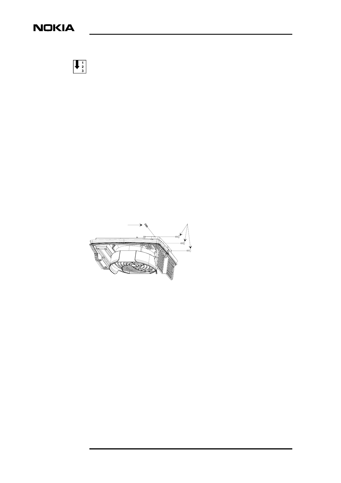
6.8.1 Replacing the HVMF cooling fan, version 1
In order to release version 1 of the fan unit’s controller module, the fan assembly
mounting must be removed from the bottom of the cabinet. To do this, the cable
entry block must first be removed.
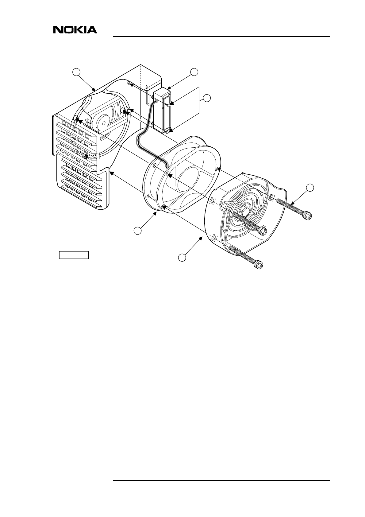
Figure 11 shows the HVMF fan assembly. For an exploded view of the fan
assembly, see Figure 12.
Releasing the cabling from the cable entry block
1. Make sure that the PSU is switched to the stand-by position and that the
power to the BTS is switched off at the main circuit breaker.
Replacing units
DN9913495 © Nokia Corporation Draft 41 (52)
Issue 3-0 en Nokia Proprietary and Confidential
Note
2. Unclip and slide the cable cover towards you.
3. Disengage and remove the cable cover support plate.
4. Remove all connecting cables to the units. If necessary, make a note of the
cable connections before removing them.
All connecting cables must be removed in order to remove the fan mounting
assembly.
5. Detach the outer sealing gasket at the point where it covers the cable entry
block, see (A) in Figure 10.
6. Remove the two 4 mm (0.157 in) Allen screws on the cable entry block.
See (B) in Figure 10.
7. Open the cable entry block at the point where the cables are routed.
8. Disengage the cables from the cable entry block.
Figure 10. Displacing the sealing strip and releasing the cables
A
Sealing strip
Allen screws
M6
Allen key 4 mm
Maintenance
42 (52) © Nokia Corporation Draft DN9913495
Nokia Proprietary and Confidential Issue 3-0 en
Replacing the HVMF fan, version 1
1. Remove the fan mounting assembly from the cabinet, as follows:
1. Remove the three T10 Torx screws and one T25 Torx screw from the
right hand side of the mounting assembly. See Figure 11.
2. Slide the mounting assembly sideways and disconnect the fan unit’s
connector from the backplane.
2. Remove the three M4 x 60 Torx screws from the fan unit (see Figure 12)
to release the fan unit and the lower fan guard.
3. Remove the two 3 x 10 self tapper screws from the fan controller module
(see Figure 12).
4. Remove the fan unit, the fan controller module, and the lower fan guard.
5. To replace the fan, reverse the procedure.
Figure 11. HVMF cooling fan assembly and mounting screws
T10
T25
Replacing units
DN9913495 © Nokia Corporation Draft 43 (52)
Issue 3-0 en Nokia Proprietary and Confidential
Figure 12. HVMF fan assembly, version 1
Maintenance
44 (52) © Nokia Corporation Draft DN9913495
Nokia Proprietary and Confidential Issue 3-0 en
Note
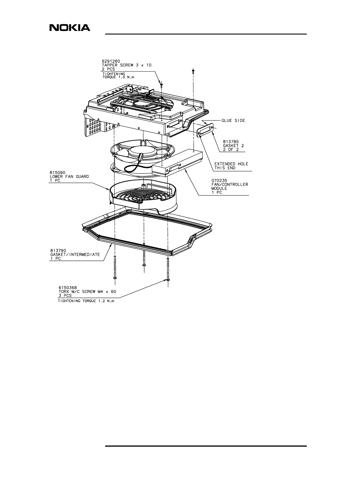
6.8.2 Replacing the HVMF cooling fan, version 2
BTS installations fitted with version 2 of the HVMF fan assembly can be
removed without removing the complete fan assembly mounting. The screws
retaining the fan unit and controller module can be reached from the underside of
the BTS. Compare Figure 13 with Figure 12.
To replace a version 1 fan unit with a version 2 fan unit which can be replaced
from the underside, the fan assembly mounting must also replaced with a version
2 compatible fan assembly mounting.
Replacing the HVMF fan, version 2
1. Make sure that the PSU is switched to the stand-by position and that the
power to the BTS is switched off at the main circuit breaker.
2. Remove the three M4 x 60 Torx screws from the fan unit to release the fan
unit and the lower fan guard. See Figure 12.
3. Remove the two 3 x 10 self tapper screws on the side of the fan controller
module. See Figure 13.
4. Remove the fan controller module from the backplane and then remove the
fan and lower fan guard.
5. To replace the fan, reverse the procedure.
Replacing units
DN9913495 © Nokia Corporation Draft 45 (52)
Issue 3-0 en Nokia Proprietary and Confidential
Legend:
1 Lower fan guard
2 Fan unit (HVMF)
3 Fan assembly mounting
4 Fan controller module
5 Tapper screws, 3x10, 2 pieces
6 Torx screws, M4x60, 3 pieces
Figure 13. HVMF fan assembly, version 2
1
2
34
6
DN0186406
5

Maintenance
46 (52) © Nokia Corporation Draft DN9913495
Nokia Proprietary and Confidential Issue 3-0 en
LED indicator conditions
DN9913495 © Nokia Corporation Draft 47 (52)
Issue 3-0 en Nokia Proprietary and Confidential
7LED indicator conditions
In addition to the alarms a network element can produce, most functional units
also have three-colour LED indicators. These indicators display the current state
of the equipment for quick, on-site reference.
This chapter specifies the meaning of the LED conditions on the following units:
• transceiver unit
• transmission unit
• power supply unit
• interface unit
• fan unit
Inform your Operations Manager of any error situations detected on the units and
enter the details in the site report.
7.1 Transceiver unit LED
The conditions on the transceiver unit’s LED indicators are specified in Table 3.
Table 3. LED conditions for TRX units
LED Colour Lit continuously Flashing
Green In service
Traffic going through
In service
No traffic going through
Yellow/Orange No LapD Configuring, not in service
Red Unit broken Unit operation degraded
Maintenance
48 (52) © Nokia Corporation Draft DN9913495
Nokia Proprietary and Confidential Issue 3-0 en
7.2 Transmission unit LED
The conditions for the transmission unit’s LED indicators are specified in Table
4.
The RRI transmission units incorporate an additional LED indicator for the
Flexbus interface. The conditions for this LED are presented in Table 5.
7.3 Interface unit LED
The conditions for the interface unit’s LED indicators are specified in Table 6.
Table 4. LED conditions for a transmission unit
LED colour Lit continuously Flashing
Green Power is on and the
operation is continuous and
error-free
Unit is currently being
accessed with a
transmission management
device
Yellow/ Orange Control or test ongoing, or
fault in incoming signal
Configuring, not in service
Red Serious fault, or an active
test interfering with normal
traffic
-
Table 5. LED conditions for an RRI transmission unit’s Flexbus LED.
LED Colour Lit continuously Flashing
Green DC power feed to the
outdoor unit and TX signal
active
DC power feed to outdoor
unit active, TX signal not
active
No light No power feed or TX signal -
LED indicator conditions
DN9913495 © Nokia Corporation Draft 49 (52)
Issue 3-0 en Nokia Proprietary and Confidential
7.4 Power supply unit LED
The condition of the power supply unit’s LED indicators are specified in Table 7.
7.5 Fan unit LED
The conditions for the fan unit’s LED indicators are specified in Table 8.
Table 6. LED conditions for an interface unit
LED colour Indication
Green OCXO operating
Yellow OCXO warming up
Red OCXO broken
Table 7. LED conditions of the power supply unit
LED colour Condition
Green Unit operating
Yellow 1. Output voltage OK, switch on the power supply
unit is in the ON position, BTS in cold start mode
2. Power shut down signal sent from the
BSC/NMS
3. Output voltage OFF because of a detected
overtemperature
Red Unit broken or short circuit in one of the BTS’s
units
Flashing yellow Input voltage OK, switch the power supply unit to
the stand-by position
Maintenance
50 (52) © Nokia Corporation Draft DN9913495
Nokia Proprietary and Confidential Issue 3-0 en
Table 8. LED conditions for the fan unit
LED colour Conditions
Green Unit operating
Yellow Operation degraded
Red Unit broken

DN9913495 ©Nokia Corporation Draft 51 (52)
Issue 3-0 en Nokia Proprietary and Confidential
Index
A
Abis loop test 18,23
adjusting the 13 MHz clock 19
antistatic wrist strap 27
B
BTS Manager 14
C
cooling fan
replacing 40
D
disposal of units 30
E
environmental data package 30
environmental precautions 14
F
Failure Report Form 13
fan unit
LED 49
maintenance 17
fault reporting 13
H
high capacity fan unit (HVMF)
replacing 40,44
I
interface unit
LED 48
replacing 38
L
LED indicator conditions 47
LEDs
fan unit 49
interface unit 48
power supply unit 49
transceiver unit 47
transmission unit 48
lock lubrication 18
M
maintenance, periodic 17
Manager software 14
master TRX, replacing 33,34
N
Nokia BTS Manager 14
P
power supply precautions 14
power supply unit
LED 49
replacing 39
R
recycling 28
removing the cover 15
replacing
cooling fan 40
HVMF fan unit, version 1 40
HVMF fan unit, version 2 44
interface unit 38
power supply unit 39
transmission unit 35
TRX units 30
replacing units 27
S
seal cleaning 18
site folder 13
slave TRX, replacing 31
T
transceiver unit (TRX)
LED 47
replacing 30
replacing master TRX 33,34
replacing slave TRX 31
transmission unit
LED 48
replacing 35
troubleshooting 23