Nokia Solutions and Networks WTFA-01 GSM 800 Transciever User Manual dn991456x3x0xen
Nokia Solutions and Networks GSM 800 Transciever dn991456x3x0xen
Contents
Installation

Nokia MetroSite EDGE Base Station
DN991456 © Nokia Corporation 1 (72)
Issue 3 en Nokia Proprietary and Confidential
Installation

Installation
2 (72) © Nokia Corporation DN991456
Nokia Proprietary and Confidential Issue 3 en
The information in this documentation is subject to change without notice and describes only
the product defined in the introduction of this documentation. This documentation is intended
for the use of Nokia's customers only for the purposes of the agreement under which the
documentation is submitted, and no part of it may be reproduced or transmitted in any form or
means without the prior written permission of Nokia. The documentation has been prepared to
be used by professional and properly trained personnel, and the customer assumes full
responsibility when using it. Nokia welcomes customer comments as part of the process of
continuous development and improvement of the documentation.
The information or statements given in this documentation concerning the suitability, capacity,
or performance of the mentioned hardware or software products cannot be considered binding
but shall be defined in the agreement made between Nokia and the customer. However, Nokia
has made all reasonable efforts to ensure that the instructions contained in the documentation
are adequate and free of material errors and omissions. Nokia will, if necessary, explain issues
which may not be covered by the documentation.
Nokia's liability for any errors in the documentation is limited to the documentary correction of
errors. NOKIA WILL NOT BE RESPONSIBLE IN ANY EVENT FOR ERRORS IN THIS
DOCUMENTATION OR FOR ANY DAMAGES, INCIDENTAL OR CONSEQUENTIAL
(INCLUDING MONETARY LOSSES), that might arise from the use of this documentation or
the information in it.
This documentation and the product it describes are considered protected by copyright
according to the applicable laws.
NOKIA logo is a registered trademark of Nokia Corporation.
Other product names mentioned in this documentation may be trademarks of their respective
companies, and they are mentioned for identification purposes only.
Copyright © Nokia Corporation 2002. All rights reserved.
DN991456 © Nokia Corporation 3 (72)
Issue 3 en Nokia Proprietary and Confidential
Hereby, Nokia Corporation, declares that this product is in compliance with the
essential requirements and other relevant provisions of Directive: 1999/5/EC.
The product is marked with the CE marking and Notified Body number according to the
Directive 1999/5/EC
FCC FCC §15.21 - Information to user - This product is used as an intentional radiated
equipment and any changes or modifications on the equipment without any approval
by Nokia could void the user's authority to operate the equipment.
FCC §15.105 - Information to user - This equipment has been tested and found to
comply with the limits for a Class B digital device, pursuant to part 15 of the FCC
Rules. These limits are designed to provide reasonable protection against harmful
interference in a residential installation. This equipment generates, uses and can
radiate radio frequency energy and, if not installed and used in accordance with the
instructions, may cause harmful interference to radio communications. However, there
is no guarantee that interference will not occur in a particular installation. If this
equipment does cause harmful interference to radio or television reception, which can
be determined by turning the equipment off and on, the user is encouraged to try to
correct the interference by one or more of the following measures:
• Reorient or relocate the receiving antenna.
• Increase the separation between the equipment and receiver.
• Connect the equipment into an outlet on a circuit different from that to which the
receiver is connected.
• Consult the dealer or an experienced radio/TV technician for help.
0523

Installation
4 (72) © Nokia Corporation DN991456
Nokia Proprietary and Confidential Issue 3 en
4 (20) © Nokia Corporation DN9990375
Nokia Proprietary and Confidential Issue 3 en
For the MetroSite EDGE to be used in the USA and continue to meet the FCC
certification granted, it must be noted that the following channels are blocked and
can not be configured for use.
For use in the GSM 1900 band:
• Channel 512
• Channel 585
• Channel 586
• Channel 587
• Channel 610
• Channel 611
• Channel 612
• Channel 685
• Channel 686
• Channel 687
• Channel 710
• Channel 711
• Channel 712
• Channel 735
• Channel 736
• Channel 737
• Channel 810
For use in the GSM 800 band:
• Channel 128
• Channel 181
• Channel 182
• Channel 183
• Channel 231
• Channel 232
• Channel 233
• Channel 239
• Channel 240
• Channel 251
If these channels are not blocked from use the FCC certification will be invalid.
DN991456 © Nokia Corporation 5 (72)
Issue 3 en Nokia Proprietary and Confidential
Contents
Contents 5
List of tables 6
List of figures 7
1 About this document 11
2 Working order 13
3 Preparations for installation 15
3.1 Checking the delivery 15
3.2 Checking the site 15
3.2.1 BTS interfaces and cables 16
3.3 Installation equipment 16
4 Unpacking the delivery 19
4.1 Working order for unpacking 19
4.2 Contents of the BTS transportation package 21
4.3 Contents of the pole mounting kit 22
5 Removing the units 25
6 Mounting the BTS 29
6.1 Wall mounting 30
6.2 Pole mounting 34
6.2.1 Attaching the cabinet with the small-pole mounting kit 35
6.2.2 Attaching the cabinet with the large-pole mounting kit 41
7 Reinstalling the units 49
8 Cabinet cabling 51
8.1 Preparations for cabling 51
8.2 Grounding 53
8.3 Power supply 55
8.4 Transmission unit 58
8.4.1 FC E1/T1 transmission unit 58
8.4.2 FXC E1 transmission unit 60
8.4.3 FXC E1/T1 transmission unit 61
8.4.4 FXC RRI transmission unit 62
8.5 Interface unit 63
8.6 Transceiver units (TRXs) 64
8.7 Completing the cabling 66
9 Completing the installation 69
Index 71

Installation
6 (72) © Nokia Corporation DN991456
Nokia Proprietary and Confidential Issue 3 en
List of tables
Table 1. Working order for installing the Nokia MetroSite EDGE Base Station 13
Table 2. Installation equipment checklist 16
Table 3. Pre-installation parts checklist 17
Table 4. Checklist for contents of the transportation package for the Nokia
MetroSite EDGE Base Station 21
Table 5. Checklist for contents of the optional pole mounting kit 22
Table 6. Parts required for wall mounting 30
Table 7. Parts and pole diameters required for pole installation 34
Table 8. Band length for different pole diameters 41

DN991456 © Nokia Corporation 7 (72)
Issue 3 en Nokia Proprietary and Confidential
List of figures
Figure 1. Contents of the Nokia MetroSite EDGE Base Station transportation
package when unpacked 22
Figure 2. Contents of the optional pole mounting kit 23
Figure 3. Connecting the antistatic wrist strap before removing any units 25
Figure 4. Removing the units 27
Figure 5. Mounting rack dimensions and screw holes 29
Figure 6. Cardboard template for aligning wall mounting screw holes 31
Figure 7. Wall mounting 33
Figure 8. Bracket blocks for pole mounting 35
Figure 9. Pre-assembling the pole brackets 36
Figure 10. Attaching the mounting rack and the pole brackets 38
Figure 11. Pole mounting with the small-pole mounting kit 40
Figure 12. Pole bracket pre-assembled (large-pole mounting kit) 42
Figure 13. Pole bracket pre-assembled (large-pole mounting kit) 43
Figure 14. Attaching the mounting rack and the pole brackets 45
Figure 15. Pole mounting with large-pole mounting kit 47
Figure 16. Displacing the sealing strip and removing the cable entry block
screws 52
Figure 17. Cable routing through the cable entry block 53
Figure 18. Grounding connector alternatives 54
Figure 19. Power supply unit and power connector alternatives 57
Figure 20. Cabling alternatives for the FC E1/T1 transmission unit 59
Figure 21. Cabling of the FXC E1 transmission unit 60
Figure 22. Cabling of the FXC E1/T1 transmission unit 61
Figure 23. Cabling of the FXC RRI transmission unit 62
Figure 24. Cabling of the interface unit 63
Figure 25. Examples of diversity cabling alternatives 65
Figure 26. Routing the cables and closing the cable cover 67
Figure 27. Hanging the BTS cover 70

Installation
8 (72) © Nokia Corporation DN991456
Nokia Proprietary and Confidential Issue 3 en

DN991456 © Nokia Corporation 9 (72)
Issue 3 en Nokia Proprietary and Confidential
Summary of changes
Version 1, 12th November 1999
Version 2, 22nd June 2000:
• Changed title
• Added GSM reference to body text
• Added CE marking
• Removed RX diversity cable from 2+1 TRX of Figure 24
• Edited Figure 26
• Removed note from alternative 1 procedure in Chapter 6.3.2
• Added BTS safety strap to Figure 1 and to list in Chapter 2.1
Version 3, 18th April 2001:
• Updated for EDGE
• Document restructured
Version 3.1, July/October 2002:
• Modifications to pole mounting kit incorporated (two types of band and
locking device)
• Note added about horizontal mounting of WCUA cover

Installation
10 (72) © Nokia Corporation DN991456
Nokia Proprietary and Confidential Issue 3 en
About this document
DN991456 © Nokia Corporation 11 (72)
Issue 3 en Nokia Proprietary and Confidential
Caution
1About this document
This document describes the installation of the Nokia MetroSiteTM EDGE Base
Station from delivery of the BTS package to the site to BTS commissioning. Read
carefully Nokia MetroSite EDGE Base Station: Warnings and Cautions and
Nokia MetroSite EDGE Base Station: Requirements for Installation and
Operation before starting the installation.
The following information can be found in this document:
• Working order for installation
• Preparations before installation
• Tools and parts required
• How to safely unpack the delivery
• Contents of the BTS delivery
• How to remove and reinstall units
• How to install the BTS on a wall or a pole
• How to cable the BTS
• Completing the installation after commissioning
Installation, commissioning and maintenance of the Nokia MetroSite EDGE Base
Station (BTS) may be performed only by trained and authorised personnel.

Installation
12 (72) © Nokia Corporation DN991456
Nokia Proprietary and Confidential Issue 3 en
Working order
DN991456 © Nokia Corporation 13 (72)
Issue 3 en Nokia Proprietary and Confidential
Note
2Working order
The Nokia MetroSite EDGE Base Station is installed upright on a pole or a wall.
Pole mounting requires a pole mounting kit, which is ordered separately when
required. The BTS can also be installed horizontally on its back.
Horizontal mounting of the Nokia MetroSite EDGE Base Station is only suitable
for certain site conditions and countries. Contact your Nokia dealer for advice.
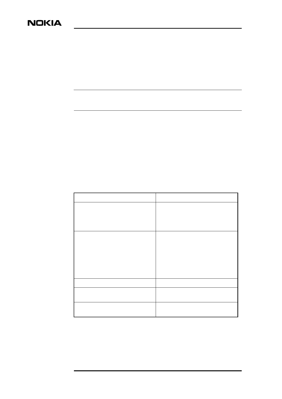
Refer to Table 1for the working order and location of instructions for installing
the Nokia MetroSite EDGE Base Station. Removing the units before mounting is
optional, depending on the number of installation personnel on the site.
Table 1. Working order for installing the Nokia MetroSite EDGE Base
Station
Activity Instructions
Preparations for installation Chapter 3
Unpacking and checking the delivery Chapter 4
Removing units to reduce weight when
mounting the cabinet (optional)
Chapter 5
Mounting the BTS on a pole or wall Chapter 6
Reinstalling units Chapter 7
Cabling the BTS Chapter 8
Completing the installation Chapter 9

Installation
14 (72) © Nokia Corporation DN991456
Nokia Proprietary and Confidential Issue 3 en
Preparations for installation
DN991456 © Nokia Corporation 15 (72)
Issue 3 en Nokia Proprietary and Confidential
Note
Caution
3Preparations for installation
Before beginning installation, check the delivery, the site, and the required tools
and extra parts against the relevant checklists.
The installation of the Nokia MetroSite EDGE Base Station can be carried out by
one person if units are removed before mounting the cabinet. However, it requires
at least two people to lift a BTS with its units installed.
Use only trained and authorised personnel for installing and commissioning the
Nokia MetroSite EDGE Base Station.
3.1 Checking the delivery
Before unpacking any of the packages, check that the delivery is correct. Confirm
that the delivery notes on each package agree with the order note.
3.2 Checking the site
The BTS site has been planned and prepared according to the specifications given
in Nokia MetroSite EDGE Base Station: Requirements for Installation and
Operation. Before beginning installation, check the site against these
specifications using a site preparation checklist.
If the site conditions do not conform to the checklist, stop the installation at this
stage and return to the site preparation procedures.
Installation
16 (72) © Nokia Corporation DN991456
Nokia Proprietary and Confidential Issue 3 en
Note
3.2.1 BTS interfaces and cables
Depending on the site solution, check that the appropriate interface units and
cables are on the site if cabling is to be completed during one installation. Details
of the required connectors and cables are found in Nokia MetroSite EDGE Base
Station: Requirements for Installation and Operation.
Diversity cables are delivered with the BTS in the transportation package.
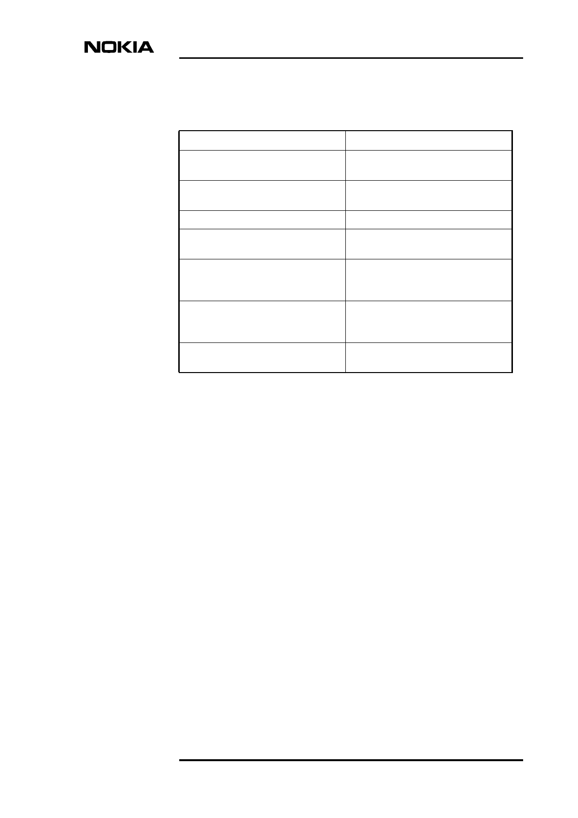
3.3 Installation equipment
Make sure that all the necessary installation equipment is available on the site
before beginning installation. Refer to Table 2 for tools and Table 3 for parts.
Detailed information on the installation equipment can be found in Nokia
MetroSite EDGE Base Station: Requirements for Installation and Operation.
Table 2. Installation equipment checklist
Tool Notes
Torque driver with 60 mm shaft and:
• T10 Torx bit
• 4 mm Allen bit
Required for:
• Unit retaining screws
• BTS fixing screws, cable entry block
screws, ground cable fixing
Torque socket spanner/wrench with 80
mm extension shaft and:
• 6 mm Allen bit
• 8 mm hexagon socket
• 10 mm hexagon socket
Required for:
• Bolts in pole brackets, L-beam
screws
• Locking device for pole brackets,
grounding cable nut
• Removing grounding bridges on
transmission units
Torque key For attaching diversity cables
Side cutting pliers For cutting cable ties and preparing
grounding cable for crimp terminal
Crimping tool For attaching crimp connector to cable in
grounding alternative 1
Preparations for installation
DN991456 © Nokia Corporation 17 (72)
Issue 3 en Nokia Proprietary and Confidential
Table 3. Pre-installation parts checklist
Part Notes
BTS transportation package Confirm that the correct package has
been delivered
Optional pole mounting kit For pole mounting, ordered from Nokia
if required
BTS interfaces and cables Depending on the site solution
Wall screws and anchor plugs Supplied by installer for wall mounting,
refer to Table 6 for screw specifications
Flat crimp terminal Supplied by installer for attaching
grounding cable to grounding point,
alternative 1
Cable shoe terminal Supplied by installer for attaching
grounding cable to grounding point,
alternative 2
Plastic cable ties supplied by installer for securing cable
routing out of the BTS

Installation
18 (72) © Nokia Corporation DN991456
Nokia Proprietary and Confidential Issue 3 en
Unpacking the delivery
DN991456 © Nokia Corporation 19 (72)
Issue 3 en Nokia Proprietary and Confidential
WARNING
4Unpacking the delivery
The Nokia MetroSite EDGE Base Station is delivered in a transportation package
with all the ordered units pre-installed in the chassis. . The transportation package
also includes equipment needed in the installation of the base station.
A pole mounting kit is required if the BTS will be mounted on a pole. This is
ordered and delivered separately if needed.
Lifting a BTS complete with units requires at least two people. The Nokia
MetroSite EDGE Base Station weighs 28 to 40 kg (62 to 88 lb), depending on
the number of TRXs installed.
4.1 Working order for unpacking
The procedures for unpacking include careful checking of the condition and
contents of the delivery. If any defects or missing parts are noticed, the
installation should be stopped and replacement parts ordered.
The following procedures should be followed in sequence.
Check the contents of the pole mounting kit
• If pole mounting is being used, check the completeness of the pole
mounting kit against the checklist in Table 5.
Remove the BTS from the packaging
1. Remove the plastic wrapping from the BTS transportation package.
Installation
20 (72) © Nokia Corporation DN991456
Nokia Proprietary and Confidential Issue 3 en
Note
2. Lift the BTS out of the package and lay it horizontally. Do not stand the
BTS in a vertical position. Lay the BTS onto a clean or covered surface, not
directly onto the ground.
3. Save the packing cardboard from the package! The cardboard can be used
as a template for defining clearances around the BTS and for marking drill
hole locations for wall installation.
Check the contents of the BTS transportation package
1. Check the completeness of the delivery against the general contents
checklist in Table 4.
2. Visually inspect the cover of the BTS for any defects.
Remove the BTS cover
1. Inspect the cover visually for defects before removing it.
2. Open the lock on the bottom of the BTS using the key provided. The key
will remain in the lock whenever the lock is in the open position.
3. Loosen the cover by sliding it along the chassis to disengage the hooks
which hold it in place. Lift the cover off when the hooks are disengaged.
Check the BTS
1. Check the completeness of the delivery against the order specifications to
confirm that the delivery contains the correct unit types.
2. Visually inspect the interior of the BTS for any defects.
The unused connectors on the units are protected with rubber caps. Leave the cap
on the connector if the connector is not going to be used for cabling.
Unpacking the delivery
DN991456 © Nokia Corporation 21 (72)
Issue 3 en Nokia Proprietary and Confidential
Remove the mounting rack
1. Make sure that you have removed the BTS cover and prepared a clean
surface for working on the BTS.
2. Turn the BTS over and lay it flat on its front.
3. The mounting rack is attached to the back of the BTS for transportation. It
must be removed before continuing with installation. The mounting rack
can be seen in detail in Figure 7. Loosen the offset screws on the bottom
and the top of the mounting rack: on the L-beam and screws B1 and B2. Do
not remove the screws completely.
4. Remove the wooden spacer blocks and the mounting rack.
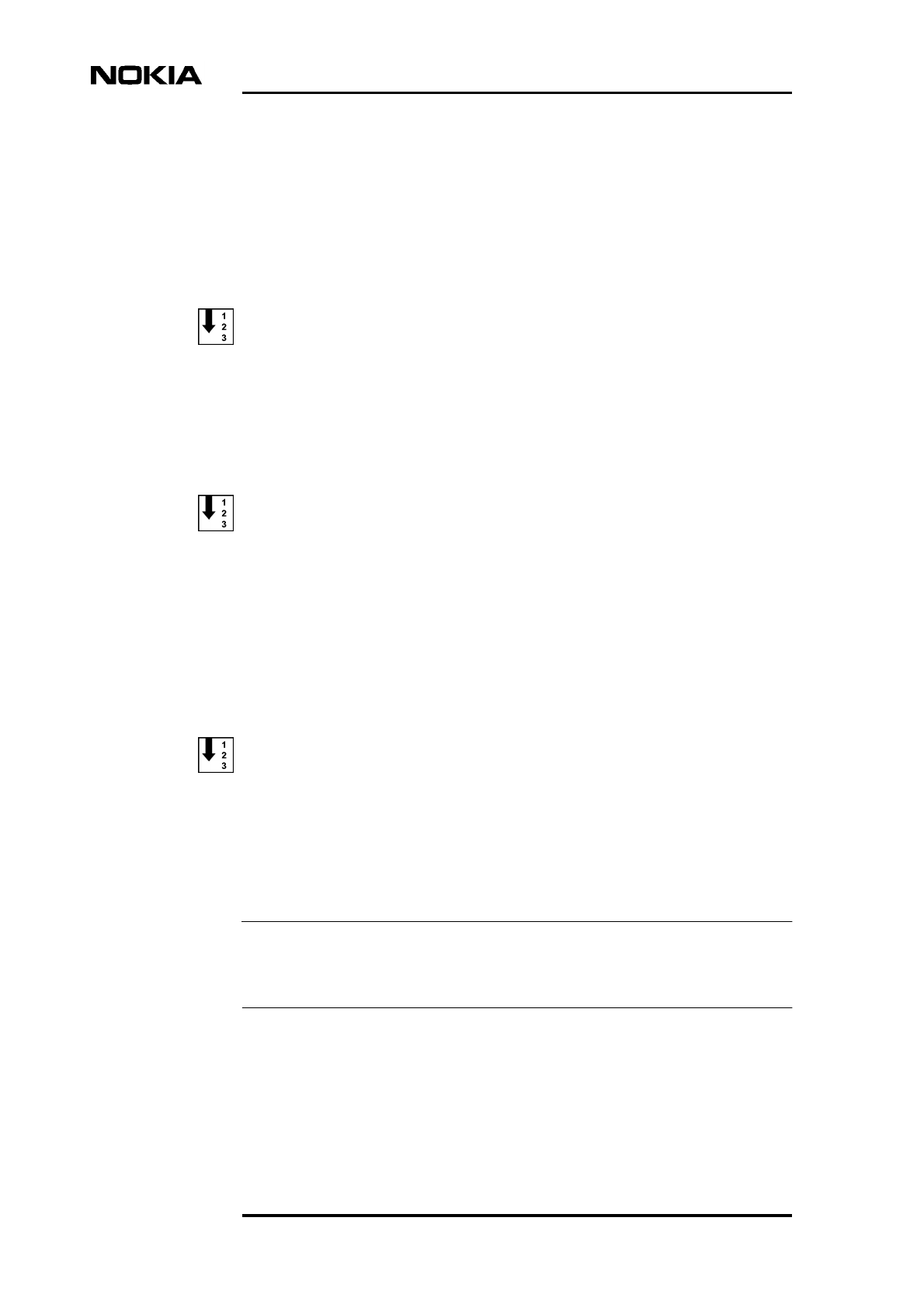
4.2 Contents of the BTS transportation package
Refer to Table 4 and Figure 1 for the contents of the transportation package for
the Nokia MetroSite EDGE Base Station.
Table 4. Checklist for contents of the transportation package for the Nokia
MetroSite EDGE Base Station
Part Notes
BTS chassis with the ordered units pre-
installed.
Shield units are installed in the slots that
are not populated with functional units
BTS cover
T-shaped mounting rack Provides the fixing base for the BTS
Two Allen screws, M6 x 20 For fixing the BTS to the mounting rack
Cable cover For cables routed out of the BTS
Cable cover support Mounting for the cable cover
Diversity cables
Safety strap For securing the cover to the chassis
Four unit retaining screws Spare parts
Spare counterparts for the unit retaining
screws
Attached to the uppermost TRX guide
beam on the top of the BTS
Key for BTS lock
Installation
22 (72) © Nokia Corporation DN991456
Nokia Proprietary and Confidential Issue 3 en
Figure 1. Contents of the Nokia MetroSite EDGE Base Station transportation
package when unpacked
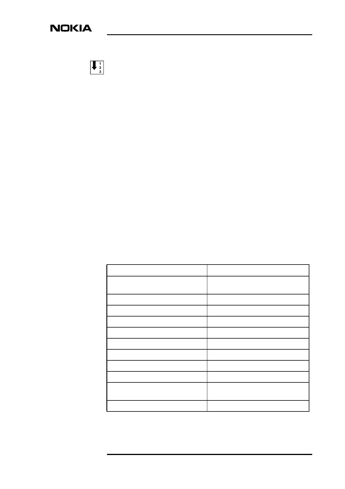
4.3 Contents of the pole mounting kit
The pole mounting kit is ordered as an option when required. Refer to Table 5 and
Figure 2 for the contents of the pole mounting kit.
Nokia Metro
S
ite BT
S
cover and chassis
with the ordered units
Cable cover support
4 unit retaining
screws
(spare parts)
Mounting rack
Cable cover
U-plate
Washer
Safety strap
Table 5. Checklist for contents of the optional pole mounting kit
Part Notes
Two front bracket blocks Upper and lower bracket blocks are
identical.
Two back bracket blocks Upper and lower bracket blocks are
identical.
Four Allen screws, M6 x 20 For fixing the front bracket blocks to the
mounting rack.
Four long bolts, M8 x 120 For fixing the back block to the front
block (smaller diameter poles).
Unpacking the delivery
DN991456 © Nokia Corporation 23 (72)
Issue 3 en Nokia Proprietary and Confidential
Figure 2. Contents of the optional pole mounting kit
Four flat washers
Four flat, square nuts, 20 x 20 x 4 mm For fixing the back bracket block to the
front bracket block (smaller diameter
poles).
Two metal bands 1010 mm (39.8 in.) For fixing the front bracket block to the
pole (larger diameter poles).
Two locking devices Worm drive clamps with hexagon
nut/screw, for tightening the metal band
to the pole (larger diameter poles). There
are two types of locking device, as
described in Section 6.2.2.
Table 5. Checklist for contents of the optional pole mounting kit (Continued)
Part Notes
Back blocks
Front blocks
Metal bands
Locking device
Allen screws
(M6x20)
M8x120 bolts
Square nuts
20x20x4 mm
Washers
DN0245446

Installation
24 (72) © Nokia Corporation DN991456
Nokia Proprietary and Confidential Issue 3 en
Removing the units
DN991456 © Nokia Corporation 25 (72)
Issue 3 en Nokia Proprietary and Confidential
Caution
5Removing the units
Units can be removed from the chassis in order to make the BTS easier to handle
during installation. The TRXs are the heaviest units, weighing approximately 4.5
kg (9.9 lb) each. Do not remove the shield units.
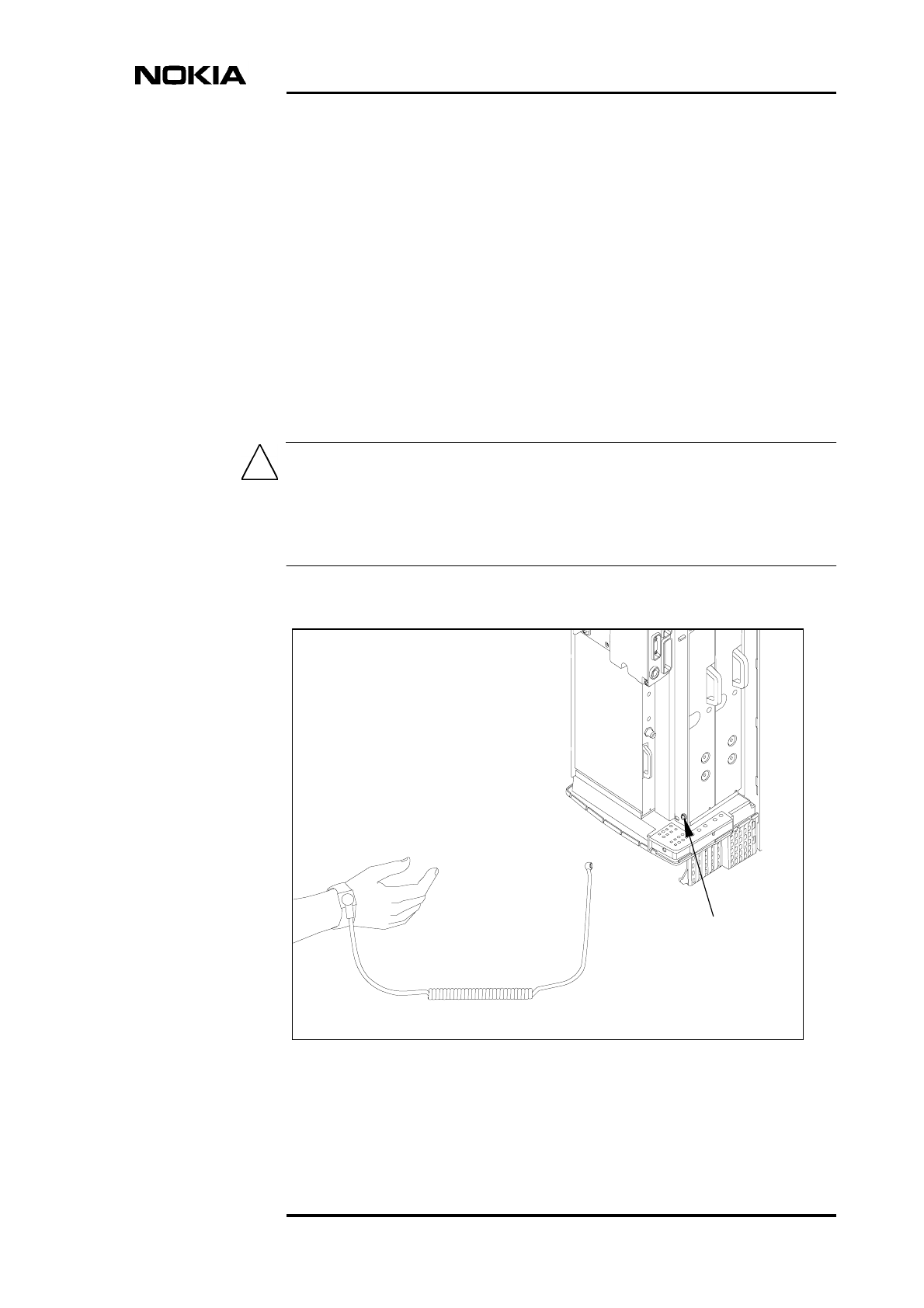
Always use the antistatic wrist strap when removing or installing the units. For
more information on electro-static discharge protection, refer to Nokia MetroSite
EDGE Base Station: Warnings and Cautions. The wrist strap and the connection
point are shown in Figure 3.
Figure 3. Connecting the antistatic wrist strap before removing any units
ESD stud
to ESD stud
Wrist strap
Installation
26 (72) © Nokia Corporation DN991456
Nokia Proprietary and Confidential Issue 3 en
Note
Caution
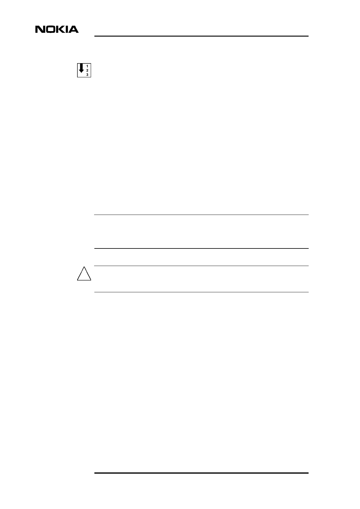
Removing a unit
1. Lay the BTS on its back, in the position shown in Figure 4.
2. Loosen the upper and lower retaining screws of the unit to be removed
using a torque driver with a T10 Torx bit.
Loosen the screws enough to remove the unit, but leave them engaged in
the threads. By doing this, the screws remain in the optimal position for
reconnecting.
3. Slide the TRX units out of the slots by pulling from the handle on the front
panel of the TRX.
4. Remove the power supply unit, interface unit, and transmission unit by
pulling each unit out until it comes to a stop. Then lift the unit upwards and
outwards to remove it. See Figure 4.
If the unit does not come out easily, rock it slightly from left to right using the
handle and then pull the unit out. Do not use excessive force!
When handling the units, beware of sharp edges!
Removing the units
DN991456 © Nokia Corporation 27 (72)
Issue 3 en Nokia Proprietary and Confidential
Caution
Figure 4. Removing the units
Handle the units with care. Do not knock the units or place them with their
connectors facing the ground. Prevent dirt, water, or snow from entering the
connectors.
Power supply unit
Interface unit
Transmission unit
Transceiver units
Unit retaining
screws

Installation
28 (72) © Nokia Corporation DN991456
Nokia Proprietary and Confidential Issue 3 en
Mounting the BTS
DN991456 © Nokia Corporation 29 (72)
Issue 3 en Nokia Proprietary and Confidential
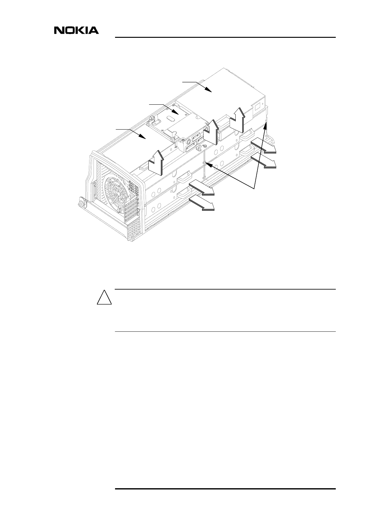
6Mounting the BTS
The mounting rack is used in both wall and pole installations to provide a fixing
base for the Nokia MetroSite EDGE Base Station. The dimensions of the
mounting rack are presented in Figure 5. Screw holes R1, R2, R3, R4, R5, and R6
are for fixing the mounting rack onto the wall or the pole bracket. Screw holes B1
and B2 are used for fixing the BTS to the mounting rack.
Figure 5. Mounting rack dimensions and screw holes
NOTE: DIMENSIONS mm (inch)
713
(28.07)
194 (7.64)
B1 B2
R1 R2
R3 R4
R5 R6
Installation
30 (72) © Nokia Corporation DN991456
Nokia Proprietary and Confidential Issue 3 en
Note
The Nokia MetroSite EDGE Base Station can be installed in a vertical position or
in a horizontal position. For more information on the permitted mounting
positions, refer to Nokia MetroSite EDGE Base Station: Requirements for
Installation and Operation.
Horizontal installation is done in the same manner as wall mounting.
Horizontal mounting is not recommended for all site conditions. Nokia MetroSite
EDGE BTSs fitted with the WCUA type cover are not suitable for horizontal
mounting. Contact your Nokia representative for more information.
6.1 Wall mounting
The mounting rack is attached to a suitable wall with screws and the BTS is then
fixed to the mounting rack. Screw hole positions are marked out on the wall using
the cardboard template which came with the BTS transportation package (see
Figure 6). The required wall screws are provided by the installer, according to the
specifications given in Table 6.
Table 6. Parts required for wall mounting
Part Notes
Mounting rack Provided in the BTS transportation
package
Cardboard template to show screw hole
positions and minimum clearance
around the BTS
Provided as part of the BTS
transportation package
Four anchor plugs for M6 wall screws To provide a secure fixing for the wall
screws
Four wall screws, M6, stainless steel,
minimum tensile strength (Rm) of 600
N/mm2
Refer to ISO 3506-1 for details
Mounting the BTS
DN991456 © Nokia Corporation 31 (72)
Issue 3 en Nokia Proprietary and Confidential
Figure 6. Cardboard template for aligning wall mounting screw holes

Installation
32 (72) © Nokia Corporation DN991456
Nokia Proprietary and Confidential Issue 3 en
Fixing the mounting rack to the wall
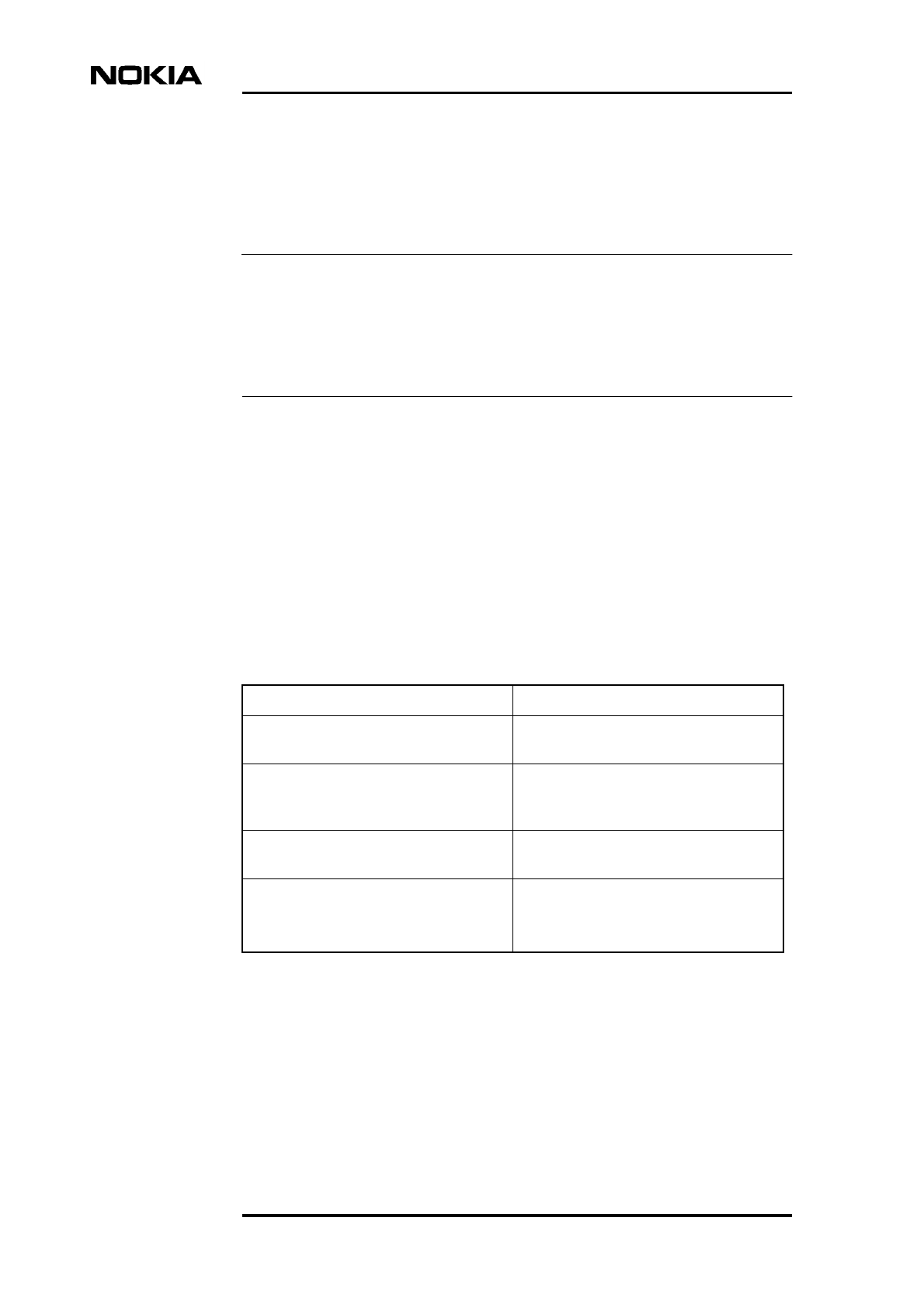
1. To define clearances required around the BTS, cut the template out of the
packing cardboard by following the dotted line (see Figure 6).
2. Find a wall area which is large enough to cover all parts of the template and
place the cardboard template on the wall at the required height. Use a spirit
level to check that the template is in a straight position.
3. Mark the fixing points on the wall for the upper screw holes of the
mounting rack (R1 and R2, see Figure 5). For example, use a centre punch
through the template to mark the fixing points.
4. Drill holes R1 and R2 in the wall and clean them out. Insert anchor plugs
(or an appropriate counterpart, depending on the material) into the wall.
5. Position the mounting rack in the correct location on the wall and attach it
with screws through holes R1 and R2 (see Figure 7). Use a spirit level to
set the mounting rack straight (adjustment is possible due to the oval shape
of holes R1 and R2). Tighten the screws when the rack is level.
6. Drill screw holes for the lower anchor screws through the holes marked R3
and R4 in Figure 7. Insert the anchor plugs (or appropriate counterparts)
into the wall.
7. Position the rectangle shaped washer over screw holes R3 and R4 and
insert and tighten the screws.
Mounting the BTS
DN991456 © Nokia Corporation 33 (72)
Issue 3 en Nokia Proprietary and Confidential
Figure 7. Wall mounting
B1
B2
Mounting rack
Attaching the BTS and
the mounting rack:
The view shows how the offset
screws and the L-beam on the
back of the cabinet are
attached to the mounting rack.
Offset fixing screws attached to the
L-beam (2 pcs)
R3
R4
B2
B1
R2
R1
Washer
L-beam
Mounting rack
Installation
34 (72) © Nokia Corporation DN991456
Nokia Proprietary and Confidential Issue 3 en
Fixing the BTS to the mounting rack
1. Hang the BTS on the upper fixing screws, B1 and B2 in Figure 7. Do not
tighten them yet!
2. Position the two offset screws which are attached to the L-beam (on the
back of the cabinet) into the offset screw slots on the lower part of the
mounting rack, as shown in the inset illustration in Figure 7.
3. Tighten the upper BTS fixing screws (B1 and B2 in Figure 7) using a
torque driver and a 4 mm Allen bit with a shaft of at least 60 mm in length.
Tighten the screws to 5.5 Nm (4.06 lb ft).
4. Tighten the offset screws on the L-beam to 12 Nm (8.85 lb ft) using a
torque socket spanner/wrench and a 6 mm Allen bit with an 80 mm
extension. See the inset illustration in Figure 7, which shows the rear view
of the cabinet.
5. If you have removed any of the units, proceed to Chapter 7. If you have not
removed any units, proceed directly to Chapter 8.
6.2 Pole mounting
Pole mounting includes three work phases:
1. Pre-assembling the pole brackets.
2. Installing the pole brackets and the mounting rack on the pole.
3. Fixing the BTS to the mounting rack.
Table 7. Parts and pole diameters required for pole installation
Part Notes
Mounting rack Provided in the BTS
transportation package
Pole mounting kit, containing:
• Small-pole kit: 2 front blocks, 2 back blocks, 4
bolts, 4 square nuts, 4 washers, 4 Allen screws
• Large-pole kit: 2 front blocks, 2 metal bands, 2
locking devices, 4 Allen screws
For poles of diameter:
• Small poles: 60 - 120 mm
(2.4 - 4.7 in)
• Large poles: 120 - 300 mm
(4.7 - 11.8 in)
Mounting the BTS
DN991456 © Nokia Corporation 35 (72)
Issue 3 en Nokia Proprietary and Confidential
Note
There are two pole mounting options available with the pole mounting kit. The
small-pole kit uses both front and back bracket blocks, but not the metal bands.
The large-pole kit is for larger diameter poles and uses the front bracket blocks
and the metal bands. Refer to Table 7 for selecting the correct mounting kit type
for the pole diameter.
There are two M6 screw holes at the ends of the upper and lower front blocks
(Figure 8) for fixing an optional cable rack.
6.2.1 Attaching the cabinet with the small-pole mounting kit
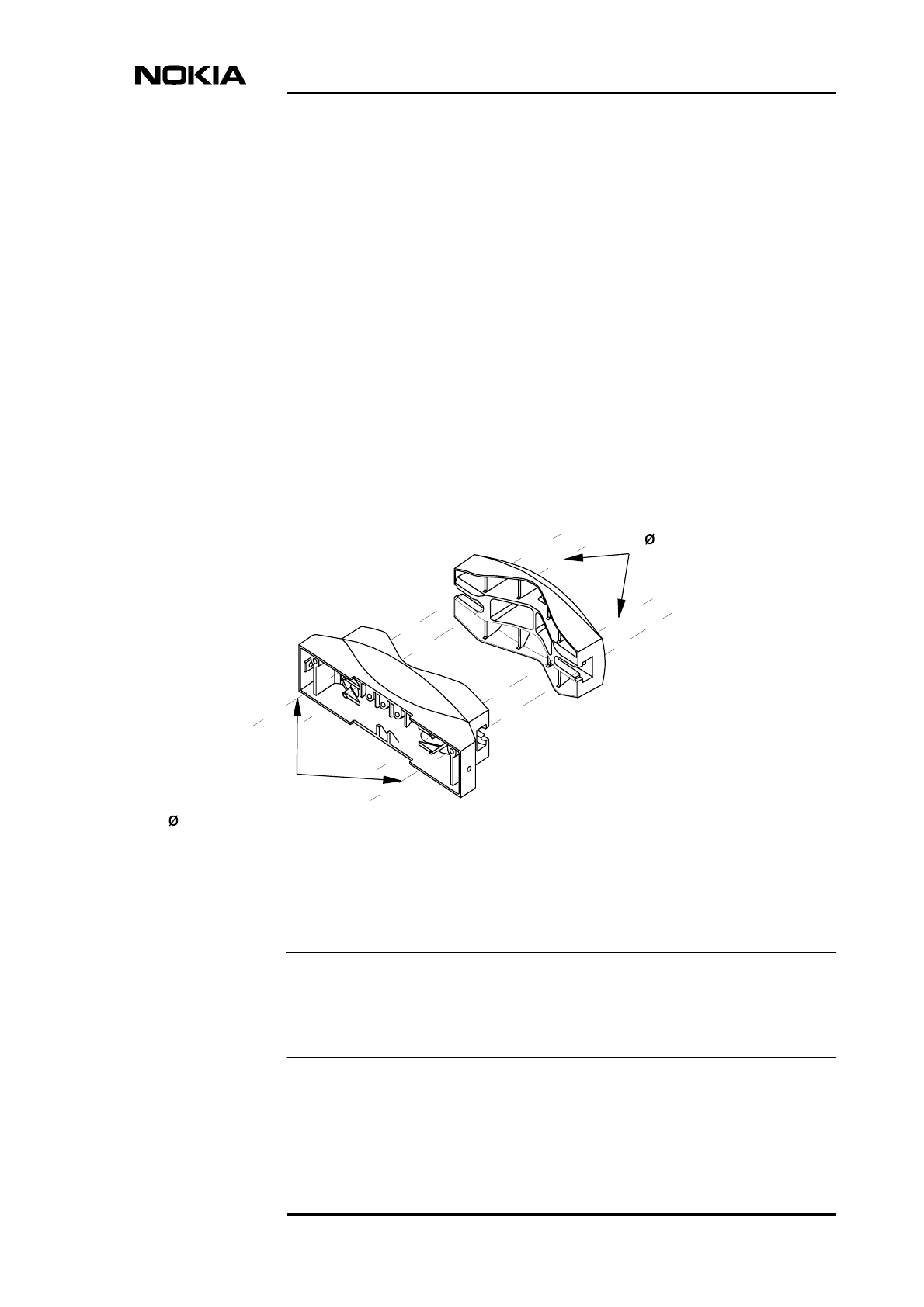
The mounting brackets (both upper and lower) consist of two blocks. The front
block is attached to the BTS mounting rack, and the back block clamps the
mounting to the pole.
The bracket blocks and their bolt holes are shown in Figure 8.
Figure 8. Bracket blocks for pole mounting
If the diameter of the installation pole is 60 to 90 mm (2.4 to 3.5 in), use the inner
bolt holes. If the diameter of the installation pole is 90 to 120 mm (3.5 to 4.7 in),
use the outer holes. Figure 9 shows the inner bolt holes being used.
Front block
Back block
Use outer bolt holes
for 90-120 (3.5-4.7) pole
Use inner bolt holes
for 60-90 (2.4-3.5) pole
NOTE: DIMENSIONS mm (inch)
Installation
36 (72) © Nokia Corporation DN991456
Nokia Proprietary and Confidential Issue 3 en
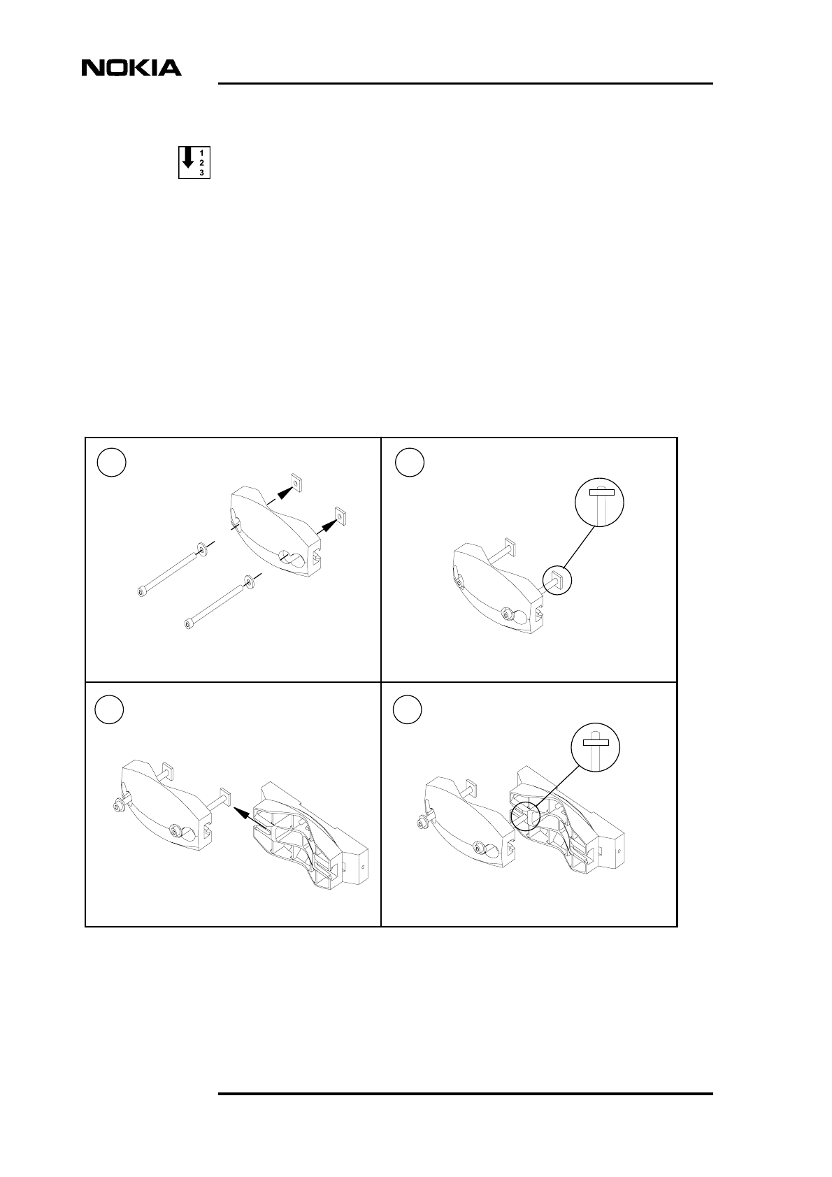
Pre-assembling the pole brackets
1. Insert the M8 assembly bolts and washers into the bolt holes in the back
blocks. See [1] in Figure 9.
2. Attach the square nuts on the ends of the bolts. Screw on the nuts just
enough to secure them on the ends of the bolts. See [2] in Figure 9.
3. Slide one of the bolts with the square nut into the slot at the side of the front
block. See [3] in Figure 9.
4. Screw the bolt in further, enough to prevent the bolt and the square nut
from sliding out from the front block. See [4] in Figure 9.
Figure 9. Pre-assembling the pole brackets
1
3
2
4
Mounting the BTS
DN991456 © Nokia Corporation 37 (72)
Issue 3 en Nokia Proprietary and Confidential
Note
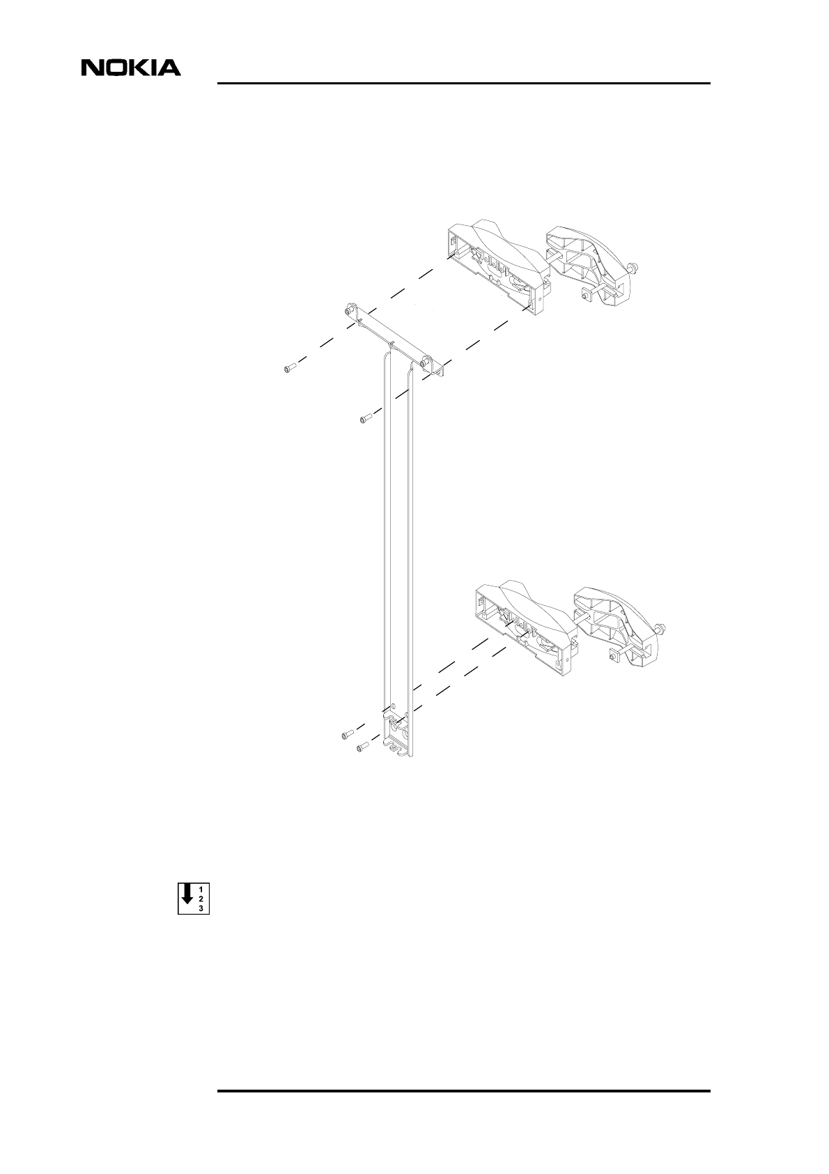
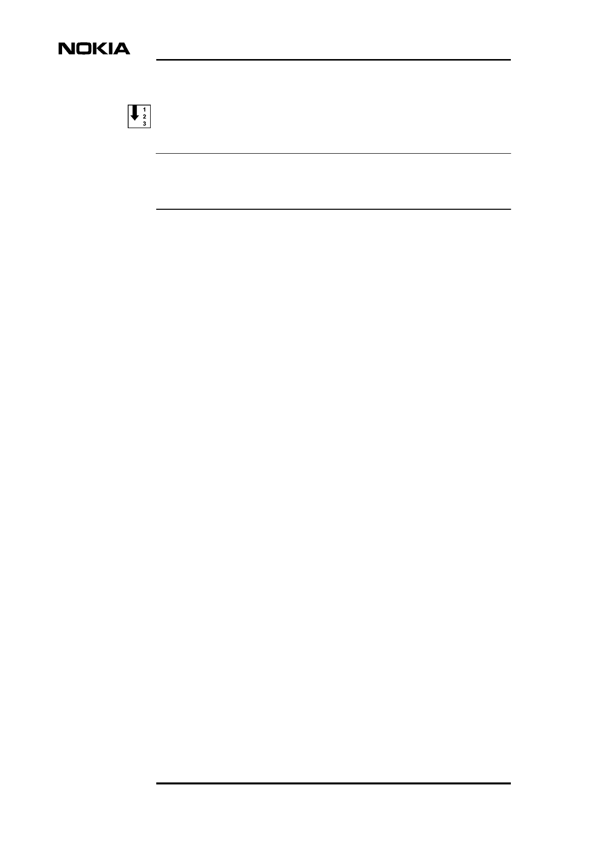
Fixing the pole brackets and the mounting rack onto a pole
Before taking the mounting rack to the pole, perform the tasks instructed in Steps
1 and 2 below.
1. To fix the upper pole bracket to the mounting rack, screw the M6 x 20
Allen screws through holes R1 and R2 into the upper front block, as shown
in Figure 10. Make sure that the front block is the correct way up (the set
of three adjacent screw holes on the back of the block should be on the
upper edge). Use a torque driver with a 4 mm Allen bit to tighten the screws
to 5.5 Nm (4.06 lb ft).
2. To fix the lower pole bracket to the mounting rack, screw the M6 x 20
Allen screws through holes R5 and R6 into the lower front block, as shown
in Figure 10. Make sure that the three adjacent screw holes are on the upper
edge of the block. Use a torque driver with a 4 mm Allen bit to tighten the
screws to 5.5 Nm (4.06 lb ft).
3. Bring the mounting rack/pole bracket combination to the pole.
4. Position the upper front block of the pole bracket on the pole. Rotate the
back block so that you can insert the free bolt and square nut into the free
slot on the other side of the front block.
5. Tighten the bolts in even stages to fix the upper pole bracket to the pole.
Use a torque socket spanner/wrench with a 6 mm Allen bit to tighten the
bolts to 12 Nm (8.85 lb ft).
6. Fix the lower bracket to the pole in the same manner as the upper bracket.
Installation
38 (72) © Nokia Corporation DN991456
Nokia Proprietary and Confidential Issue 3 en
Figure 10. Attaching the mounting rack and the pole brackets
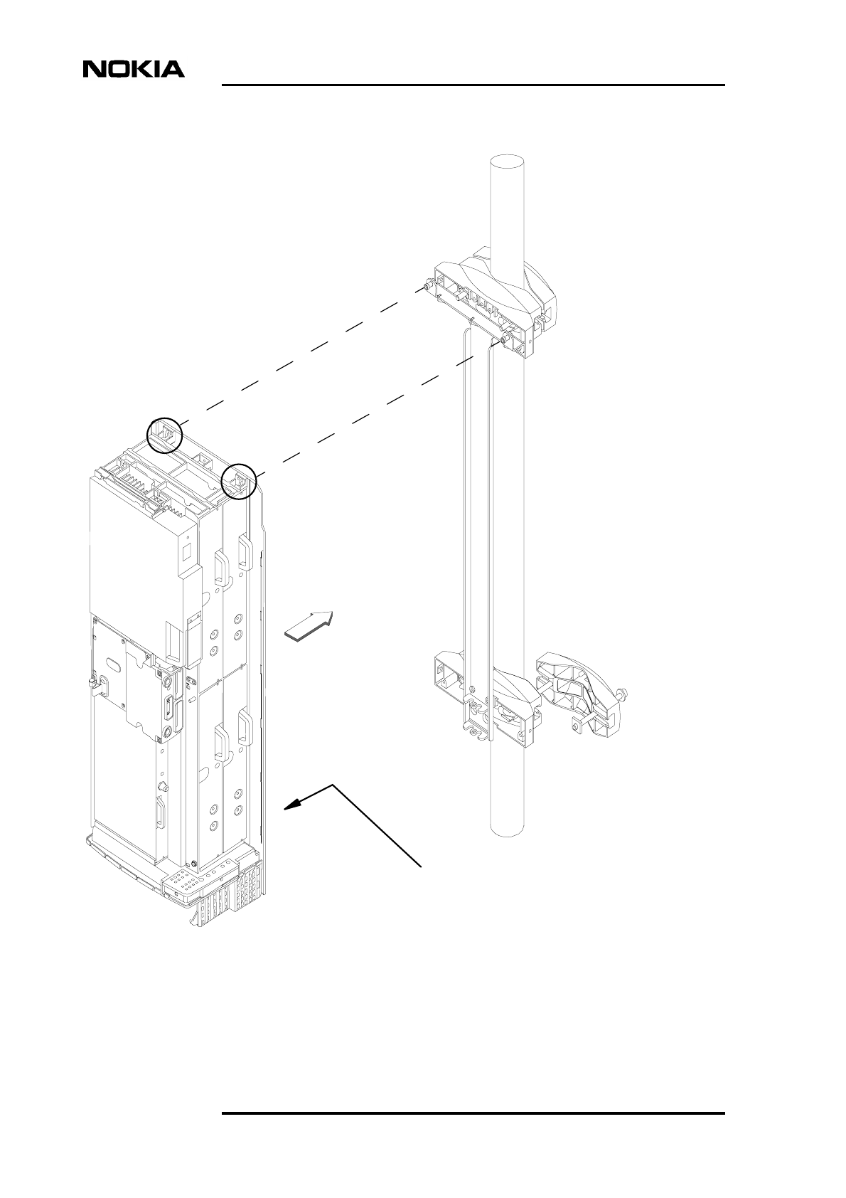
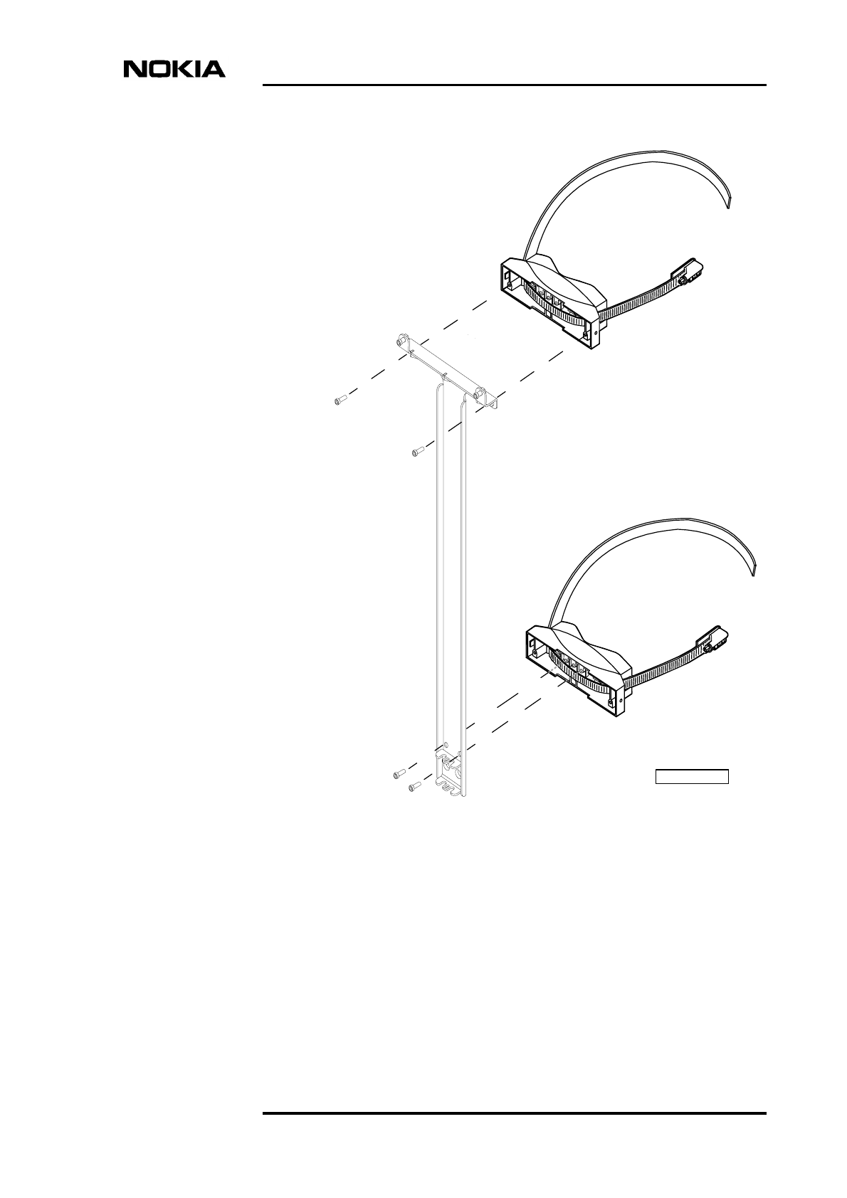
Fixing the BTS to the mounting rack
1. Bring the BTS to the mounting rack and hang it on the upper BTS fixing
screws, B1 and B2 in Figure 11. Do not tighten them yet!
B1
B2
R2
R1
R6
R5
NOTE! Make sure that
the three adjacent screw holes
are on the upper edge
of the bracket block.

Mounting the BTS
DN991456 © Nokia Corporation 39 (72)
Issue 3 en Nokia Proprietary and Confidential
2. Position the two offset screws which are attached to the L-beam (on the
back of the cabinet) into the offset screw slots in the lower part of the
mounting rack, as shown in the inset illustration in Figure 7.
3. Tighten the upper BTS fixing screws (B1 and B2 in Figure 11) to 5.5 Nm
(4.06 lb ft) using a torque driver with a 4 mm Allen bit.
4. Tighten the offset screws on the L-beam from the underside. Use a torque
socket spanner/wrench with a 6 mm Allen bit and an 80 mm extension to
tighten to 12 Nm (8.85 lb ft).
5. If you have removed any BTS units, proceed to Chapter 7. If you have not
removed any units proceed directly to Chapter 8.
Installation
40 (72) © Nokia Corporation DN991456
Nokia Proprietary and Confidential Issue 3 en
Figure 11. Pole mounting with the small-pole mounting kit
B1
B2
Mounting rack
Attach the BTS to the mounting rack
with offset screws at the BTS back side.
Mounting the BTS
DN991456 © Nokia Corporation 41 (72)
Issue 3 en Nokia Proprietary and Confidential
6.2.2 Attaching the cabinet with the large-pole mounting kit
With the large-pole mounting kit, the front bracket blocks are clamped to the pole
with a metal band and locking device.
There are two types of band and locking device. One uses grooved metal bands,
as described in procedure [A] below. The other type of locking device uses
smooth bands and a locking rack, as described in procedure [B] below. Follow the
procedure for the type of locking device and band in your kit.
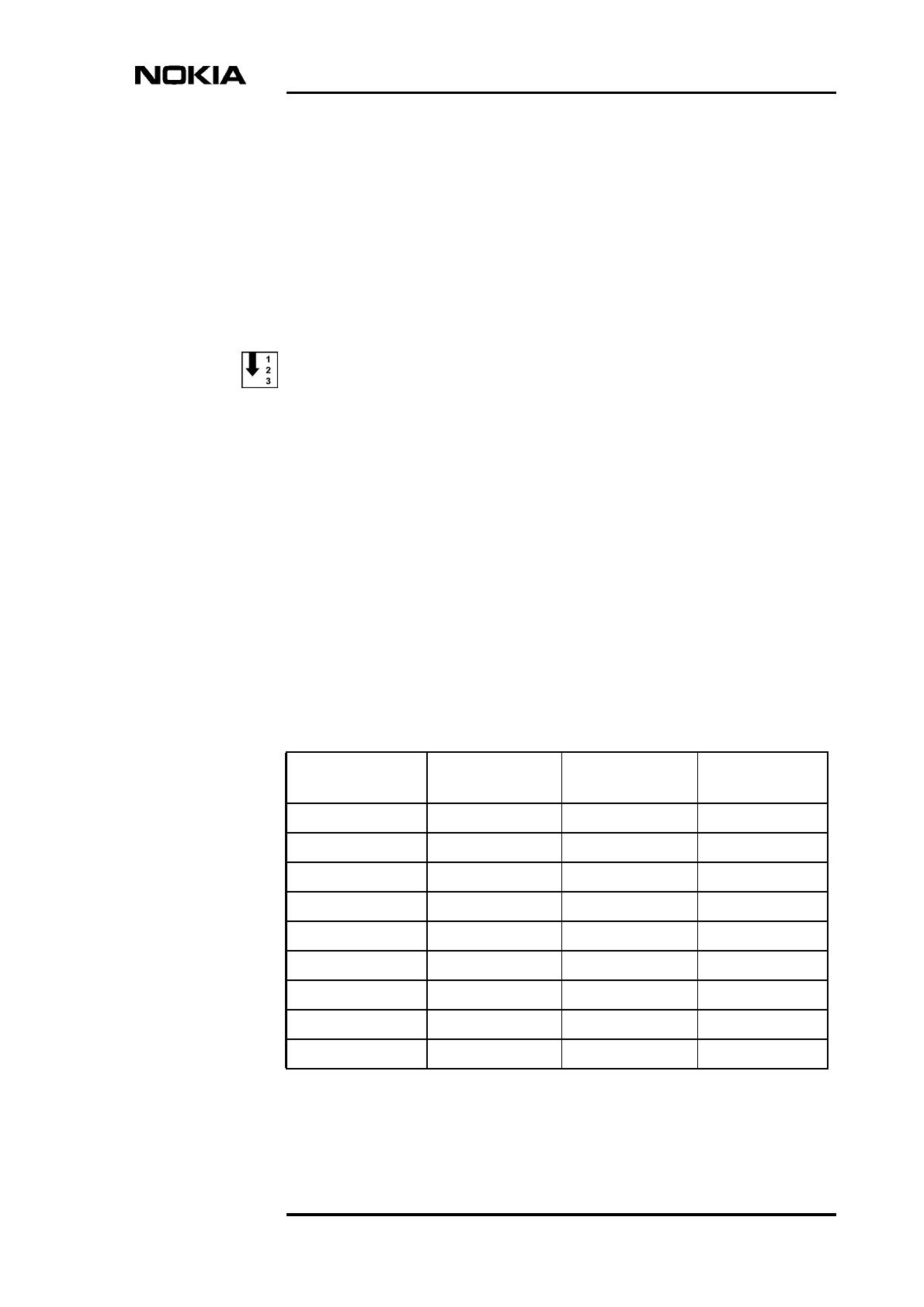
[A] Pre-assembling the pole brackets and bands (grooved band type)
1. Assemble the locking device and band by inserting the end of the metal
band approximately 25 mm (1 in.) into the locking device. The correct set
up of the parts is shown in Figure 12.
Bend the surplus end of the metal band underneath the locking device, as
shown in [3] [A] in Figure 12.
Flatten the bent-over end of the metal band to remove any distortion.
The locking device is now assembled.
2. Cut the metal band to the appropriate length, according to the pole
diameter. Refer to Table 8 below.
Table 8. Band length for different pole diameters
Pole diameter
(mm)
Band length
(mm)
Pole diameter
(in)
Band length
(in)
140 580 5.5 22.8
160 630 6.3 24.8
180 680 7.1 26.8
200 740 7.9 29.1
220 790 8.7 31.1
240 850 9.5 33.5
260 900 10.2 35.4
280 950 11.0 37.4
300 1010 11.8 39.8
Installation
42 (72) © Nokia Corporation DN991456
Nokia Proprietary and Confidential Issue 3 en
3. Route the metal band through the holes in the front block, as shown in [4],
Figure 12.
Leave the other end of the metal band free until you have completed the
next procedure (fixing the front bracket blocks to the mounting rack).
Legend:
1 Metal band
2 Locking device
3 Detail of locking device, attached to metal band
4 Detail of entry point for metal band into front bracket block
Figure 12. Pole bracket pre-assembled (large-pole mounting kit)
1
DN0245434
2
AB
3
4
Mounting the BTS
DN991456 © Nokia Corporation 43 (72)
Issue 3 en Nokia Proprietary and Confidential
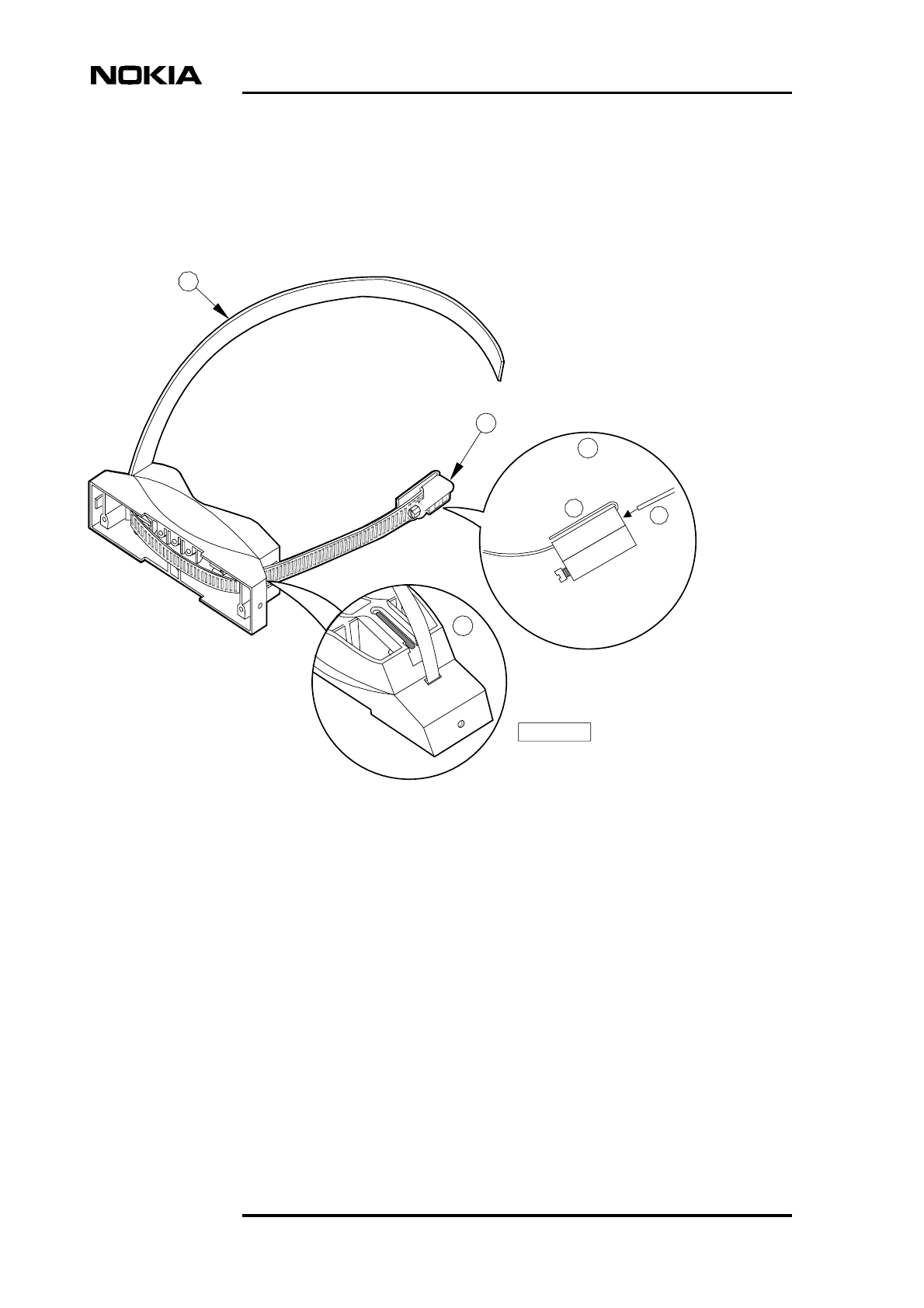
[B] Pre-assembling the pole brackets and bands (non-grooved band
type)
1. Assemble the locking device by inserting the end of the locking rack into
the worm screw housing and turning the screw to engage the rack. Make
sure you have the rack the right way round when doing this. The words
‘THIS SIDE UP’ should be visible on the rack when the locking device is
clamped around the pole. Refer to Figure 12.
2. Cut the metal band to the appropriate length, according to the pole
diameter. Refer to Table 8 above.
3. Route the metal band through the holes in the front block.
4. Bend one end of the metal band over to form a hook of about 30 mm (1.2
in) in length.
5. Insert the hook into the slot at the end of the locking rack.
6. Bend the other end of the metal band over to form another hook of about
30 mm (1.2 in) in length. Leave it free for now.
Figure 13. Pole bracket pre-assembled (large-pole mounting kit)
Locking
rack
Metal
band
Worm screw
housing
Worm screw
Installation
44 (72) © Nokia Corporation DN991456
Nokia Proprietary and Confidential Issue 3 en
Note
Fixing the pole bracket and the mounting rack to a pole
Before taking the mounting rack up the pole, perform the tasks instructed in Steps
1 and 2 below.
1. Fix the upper pole bracket to the mounting rack by screwing the M6 x 20
Allen screws through R1 and R2 into the upper front block, as shown in
Figure 14. Make sure that the front block is the correct way up (the set of
three adjacent screw holes should be on the upper edge of the bracket). Use
a torque driver with a 4 mm Allen bit to tighten the screws to 5.5 Nm (4.06
lb ft).
2. Fix the lower pole bracket to the mounting rack by screwing the M6 x 20
Allen screws through R5 and R6 into the lower block, as shown in Figure
14. Make sure that the set of three adjacent screw holes is on the upper edge
of the bracket. Use a torque driver with a 4 mm Allen bit to tighten the
screws to 5.5 Nm (4.06 lb ft).
3. Take the mounting rack/pole bracket combination to the pole.
4. Wrap the metal band of the upper bracket around the pole.
5. Insert the free end of the metal band (grooved type) into the slot on the
worm screw housing, as shown in [B] of Figure 12. Wind the metal band
into the locking device by turning the nut with a flat screwdriver or 8 mm
hexagon socket and wrench.
OR
Insert the hook-shaped free end of the band (non-grooved type) into the slot
on the worm screw housing. Tighten the worm screw using a flat
screwdriver or 8 mm hexagon socket and wrench.
6. When all the slack on the band has been wound in with the locking device,
tighten the worm screw to 10 Nm (7.4 lb ft) using a torque socket
spanner/wrench and the 8 mm hexagon socket.
7. Fix the lower bracket in the same manner as the upper bracket.
Mounting the BTS
DN991456 © Nokia Corporation 45 (72)
Issue 3 en Nokia Proprietary and Confidential
Figure 14. Attaching the mounting rack and the pole brackets
B1
B2
R2
R1
R6
R5
N
O
TE! Make sure that
the three adjacent screw holes
are on the upper edge of the
bracket block.
DN99544792

Installation
46 (72) © Nokia Corporation DN991456
Nokia Proprietary and Confidential Issue 3 en
Fixing the BTS to the mounting rack
1. Bring the BTS to the mounting rack and hang it on the upper BTS fixing
screws, B1 and B2 in Figure 15. Do not tighten them yet!
2. Position the offset screws on the L-beam (on the back of the cabinet) into
the offset screw slots on the lower part of the mounting rack, as shown in
the inset illustration in Figure 7.
3. Tighten the upper BTS fixing screws (B1 and B2 in Figure 15) to 5.5 Nm
(4.06 lb ft) using a torque driver with a 4 mm Allen bit.
4. Tighten the offset screws on the L-beam from the underside. Use a torque
socket spanner/wrench with a 6 mm Allen bit to tighten to 12 Nm (8.85 lb
ft).
5. If you have removed any units, proceed to Chapter 7. If you have not
removed any units proceed directly to Chapter 8.
Mounting the BTS
DN991456 © Nokia Corporation 47 (72)
Issue 3 en Nokia Proprietary and Confidential
Figure 15. Pole mounting with large-pole mounting kit
B1
B1
Mounting rack
Attach the BTS to the mounting rack
with offset screws at the BTS back side.
B2
B2
DN9913502

Installation
48 (72) © Nokia Corporation DN991456
Nokia Proprietary and Confidential Issue 3 en
Reinstalling the units
DN991456 © Nokia Corporation 49 (72)
Issue 3 en Nokia Proprietary and Confidential
Note
Caution
Note
7Reinstalling the units
If any units have been removed from the BTS, they can be reinstalled in any order.
If you have removed any units from the BTS, be sure to install the grounding
cable before reinstalling the units. Refer to the grounding cabling instructions in
Section 8.2.
Always use the antistatic wrist strap when removing or installing the units. For
more information on electro-static discharge protection, refer to Nokia MetroSite
EDGE Base Station: Warnings and Cautions. The wrist strap and the connection
point are shown in Figure 3.
Reinstalling units
1. Slide the unit into the appropriate slot (see Figure 4).
2. Press the unit carefully against the connectors on the backplane. Do not use
excessive force!
3. Fix and tighten the unit retaining screws. Use a torque driver with a T10
Torx bit to tighten to 1.5 Nm (1.11 lb ft).
Shield unit fixing screws may only be tightened to 1.0 Nm (0.74 lb ft).
Installation
50 (72) © Nokia Corporation DN991456
Nokia Proprietary and Confidential Issue 3 en
Caution
In order to ensure proper weather shielding, all unit retaining screws must be
tightened.
Cabinet cabling
DN991456 © Nokia Corporation 51 (72)
Issue 3 en Nokia Proprietary and Confidential
Note
8Cabinet cabling
This document assumes that you are using the ready-made cables supplied by
Nokia, or that all cables have been prefabricated before starting the cabling of the
BTS. For information on the cable types and connectors refer to Nokia MetroSite
EDGE Base Station: Requirements for Installation and Operation. For the pin
configurations refer to Nokia MetroSite EDGE Base Station: Product
Description.
The connectors on the units’ front panels are protected with rubber caps. Remove
the caps only from those connectors that will be used for BTS cabling.
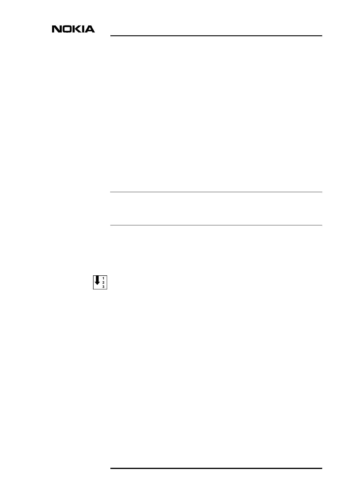
8.1 Preparations for cabling
Before starting the cabling, do the following:
1. Displace the sealing strip around the cable entry block. See [A] in Figure
16.
2. Loosen and remove the two Allen screws that keep the cable entry block in
place. Use a torque driver with a 4 mm Allen bit. For the location of the
screws, see [B] in Figure 16.
Installation
52 (72) © Nokia Corporation DN991456
Nokia Proprietary and Confidential Issue 3 en
Note
Figure 16. Displacing the sealing strip and removing the cable entry block
screws
When the screws are removed, the cable entry block can be split apart at
appropriate places for routing the cables through the cable holes. For routing the
cables through the block, see Figure 17.
A
Sealing strip
Allen screws
M6
Allen key 4 mm
Cabinet cabling
DN991456 © Nokia Corporation 53 (72)
Issue 3 en Nokia Proprietary and Confidential
WARNING
Figure 17. Cable routing through the cable entry block
8.2 Grounding
To guarantee the safety of service personnel and other users of the
telecommunication network, additional protective grounding is always
required as stated in EN 60950, “Safety of information technology
equipment, including electrical business equipment.” and UL 1950 3rd
edition. The additional external ground cable is connected to the grounding
connector.
Ensure that the ground connection is secure and non-removable.
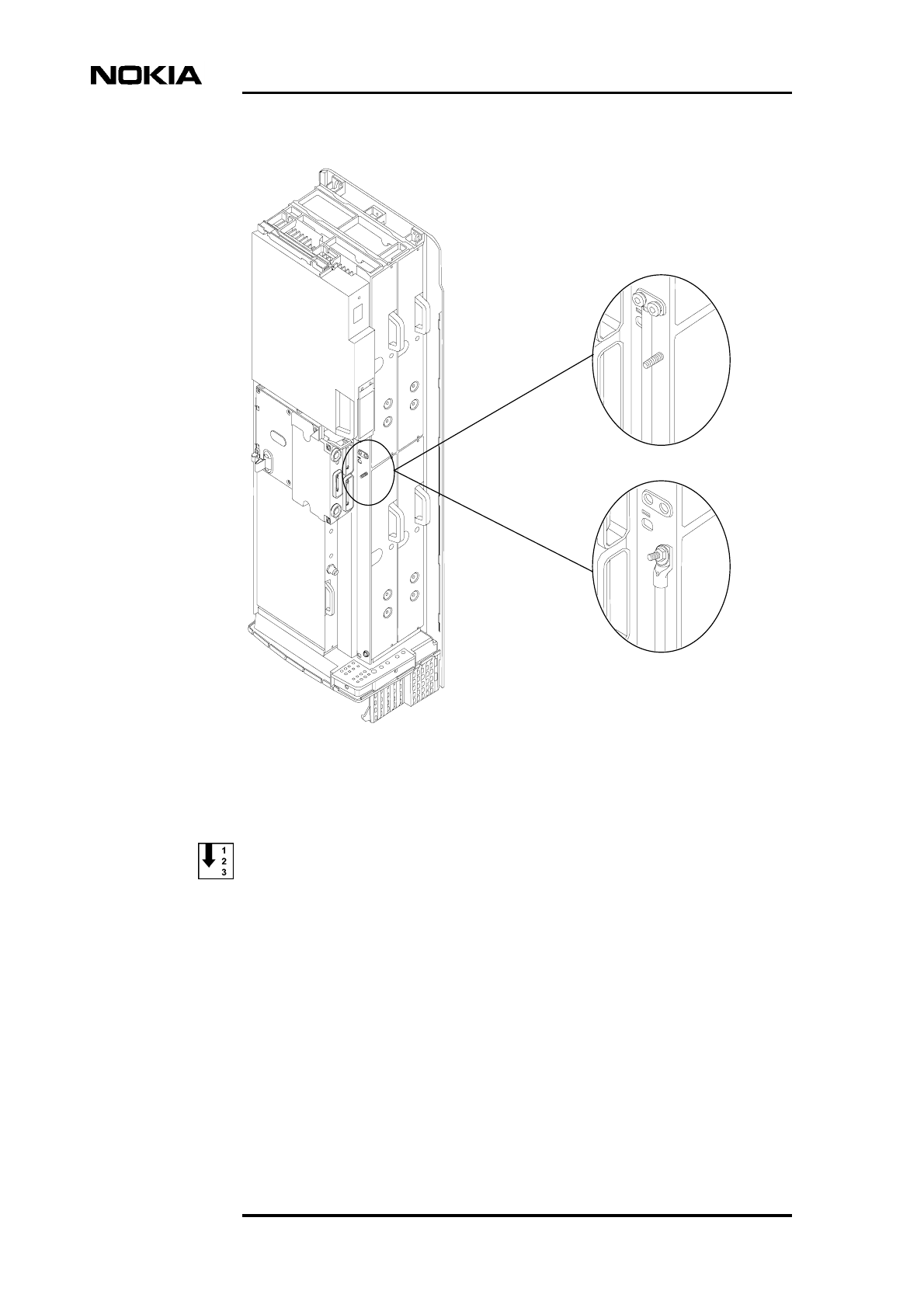
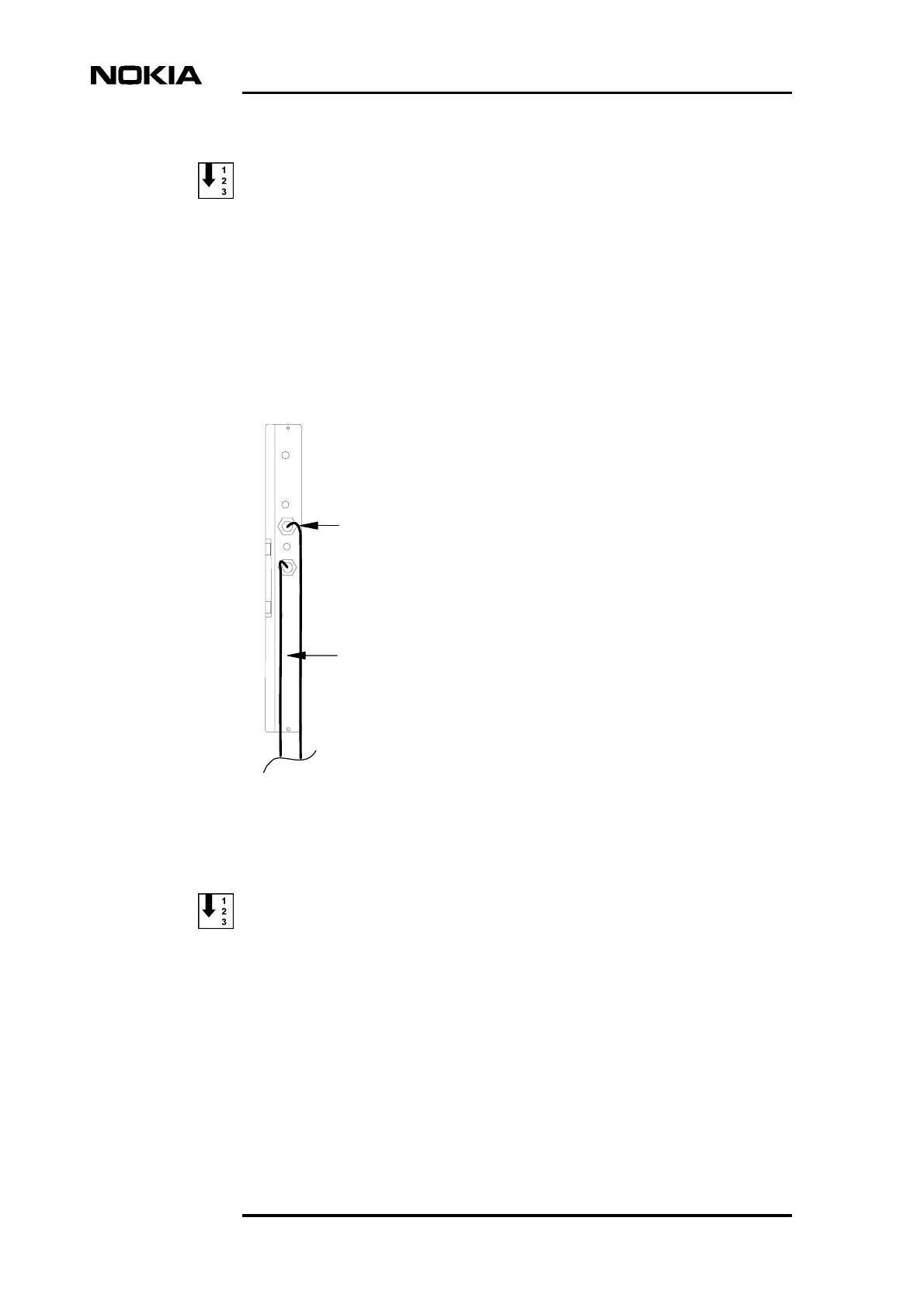
There are two alternative grounding connectors in the BTS chassis (see Figure
18). Depending on the local regulations, choose the appropriate connector for
connecting the grounding cable to the chassis. Note that the grounding cable in
alternative 2 must be fitted with a cable shoe.
Antenna
feeders
Power supply cable
Extension cables
- Grounding cable, 1 pc
- Transmission cables, max 8 pcs
- External alarms and controls
Installation
54 (72) © Nokia Corporation DN991456
Nokia Proprietary and Confidential Issue 3 en
Figure 18. Grounding connector alternatives
Connecting the ground wire to the connector, alternative 1
1. Loosen the two locking screws and washers from the grounding connector
using a torque driver with a 4 mm Allen bit.
2. Strip the end of the grounding cable using side-cutting pliers and attach a
flat crimp terminal to it. Fix the terminal to the cable with a crimping tool.
3. Insert the crimp terminal between the cabinet and the washer. Tighten the
screws.
Alternative 1
Alternative 2
Cabinet cabling
DN991456 © Nokia Corporation 55 (72)
Issue 3 en Nokia Proprietary and Confidential
WARNING
WARNING
4. Make sure that the grounding cable is correctly positioned and that the
screws are securely tightened.
Connecting the ground wire to the connector, alternative 2
1. Strip the end of the grounding cable using side-cutting pliers and attach a
cable shoe to the cable with a crimping tool.
2. Loosen and remove the locknut from the grounding stud.
3. Place the cable shoe over the grounding stud.
4. Replace the locknut on the stud and tighten with an 8 mm hexagon socket.
5. Make sure that the grounding cable is correctly positioned and that the nut
is securely tightened.
8.3 Power supply
MAINS VOLTAGE! Follow your national legislation when working with the
power supply. The Nokia MetroSite EDGE Base Station must be
permanently wired to a disconnect device (such as a circuit breaker), in
accordance with current local and national wiring standards.
The following warning applies to the AC power supply. The protective
ground wire can only be used for protective conductor installations. Using
the protective ground conductor for other purpose is dangerous to life.
Ensure that the ground connection is established before the power outlet is
connected to the BTS.
The mains power supply must be switched OFF before starting installation
of the power supply cable!
Installation
56 (72) © Nokia Corporation DN991456
Nokia Proprietary and Confidential Issue 3 en
Note
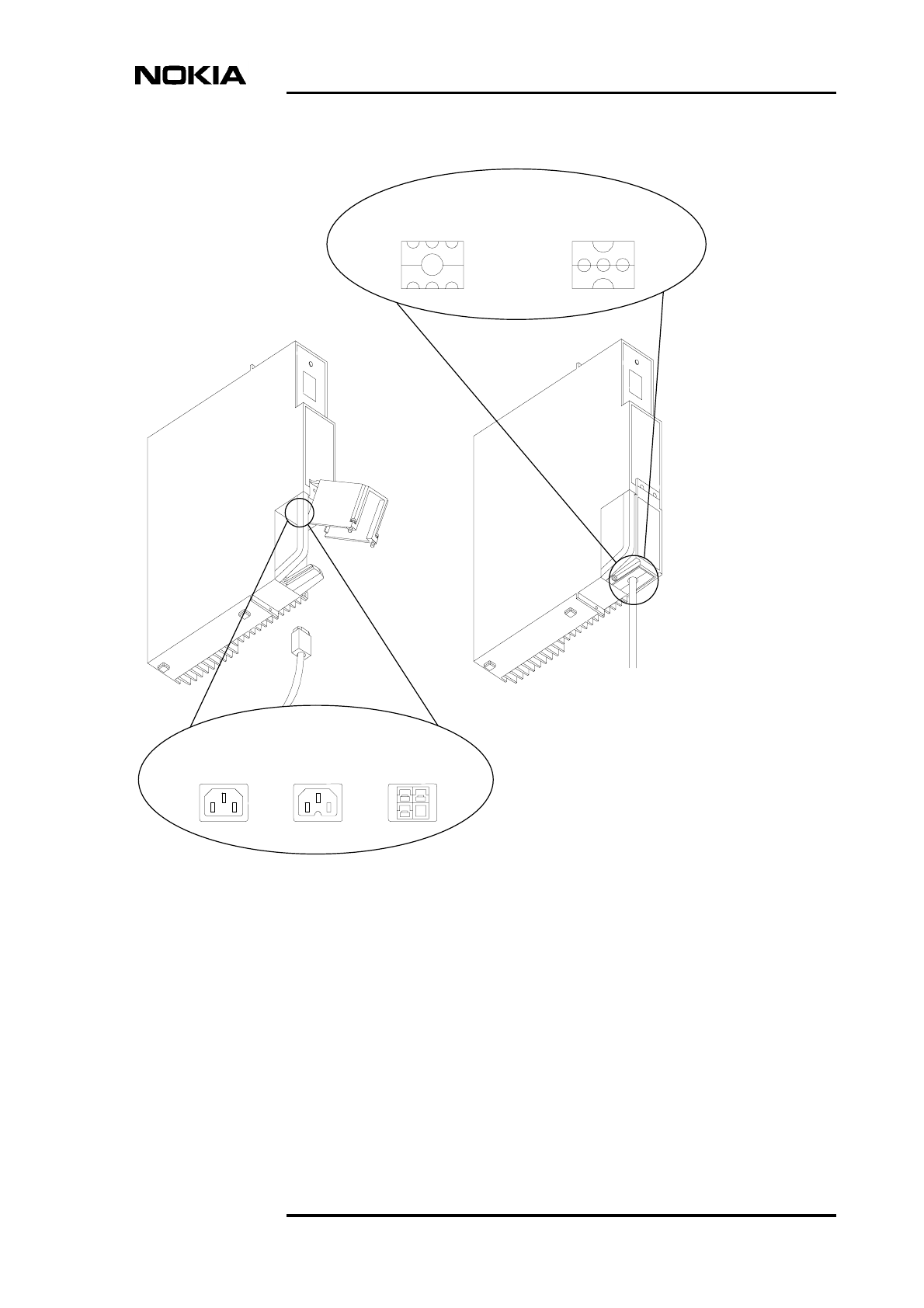
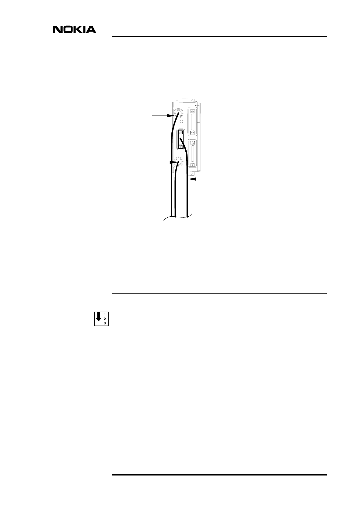
Connecting the power supply cable to the power supply unit
1. Make sure that the site’s mains power supply is switched OFF and that the
switch on the power supply unit is in the stand-by position.
2. Open the connector shield by loosening the retaining screws with a torque
driver and a T10 Torx bit (see Figure 19).
3. Open up the rubber sealing piece and route the power supply cable through
it. Close the sealing piece.
DC power can be fed in with three separate conductors. In this case, reverse the
rubber sealing piece so that the three small recesses are facing each other and
form three small holes (see Figure 19). Use the three holes for routing the
conductor cables.
4. Connect the power supply cable to the power connector in the power
supply unit.
5. Close the power supply connector shield and tighten the screws.
Cabinet cabling
DN991456 © Nokia Corporation 57 (72)
Issue 3 en Nokia Proprietary and Confidential
Figure 19. Power supply unit and power connector alternatives
AC 230 V AC 110 V DC
Connector alternatives:
Sealing for 1 wire Sealing for 3 wires
Installation
58 (72) © Nokia Corporation DN991456
Nokia Proprietary and Confidential Issue 3 en
Note
Note
8.4 Transmission unit
The cabling of the transmission unit is dependent on the transmission unit type.
This section instructs how to cable each transmission unit type.
It is a good procedure to label the TX and RX cables when you connect them to
the transmission unit. This makes any subsequent maintenance or upgrade
procedures easier.
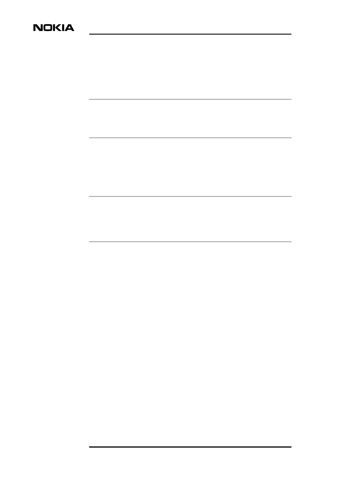
8.4.1 FC E1/T1 transmission unit
Either separate 75 Ω RX and TX connectors (type BT-43), or one 120/100 Ω
TX/RX connector (type TQ) can be used.
The 75 Ω TX and RX connectors are connected to each other with a grounding
bridge (see Figure 20). If the grounding bridge is removed, the grounding of the
RX connector’s outer conduct changes from direct grounding to capacitive
grounding.
Cabinet cabling
DN991456 © Nokia Corporation 59 (72)
Issue 3 en Nokia Proprietary and Confidential
Figure 20. Cabling alternatives for the FC E1/T1 transmission unit
Cabling an FC E1/T1 75 Ω transmission unit
1. If you want to remove the grounding bridge (see Figure 20), use a 10 mm
hexagon socket to loosen both connectors and pull out the bridge. Re-
tighten the connectors.
2. Connect the connector of the received (RX) signal line to the 75 Ω RX
connector on the FC E1/T1 front panel.
3. Connect the connector of the transmitted (TX) signal line to the 75 Ω TX
connector on the FC E1/T1 front panel.
Cabling an FC E1/T1 120/100 Ω transmission unit
• Connect the connector of TX/RX signal line to the 100/120 Ω TX/RX
connector on the FC E1/T1 front panel (see Figure 20). Tighten the
connector nut properly.
RX line
TX line
RX/TX line
FC E1/T1
120/100
75
Grounding
bridge
Installation
60 (72) © Nokia Corporation DN991456
Nokia Proprietary and Confidential Issue 3 en
Note
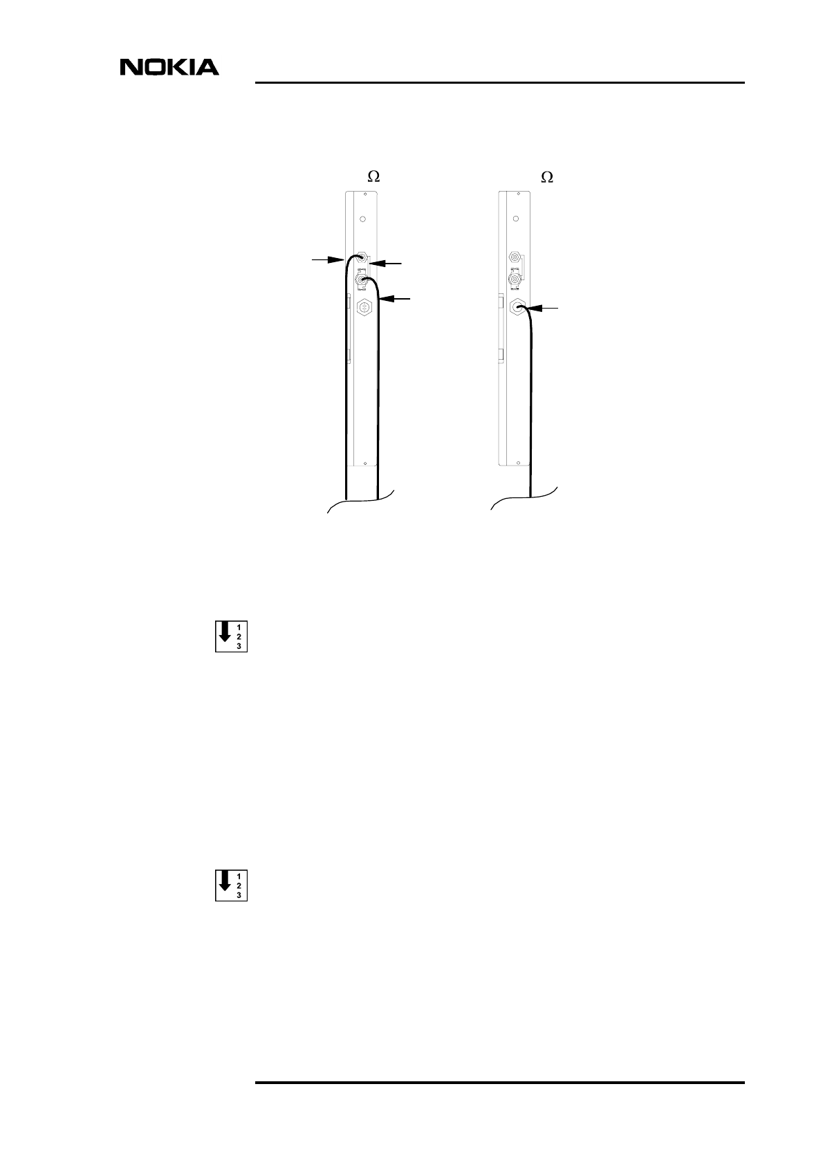
8.4.2 FXC E1 transmission unit
The FXC E1 has four pairs of 75 Ω connectors (type BT-43). Each pair forms a
transmission interface (IF). The upper connector is always the TX connector of
any given transmission interface. The lower connector is always the RX
connector of any given transmission interface (see Figure 21).
The 75 Ω TX and RX connectors are connected to each other with a grounding
bridge (see Figure 21). If the grounding bridge is removed, the grounding of the
RX connector’s outer conduct changes from direct grounding to capacitive
grounding.
Figure 21. Cabling of the FXC E1 transmission unit
RX line, IF4
TX line, IF4
TX line, IF3
RX line, IF3
RX line, IF2
TX line, IF2
TX line, IF1
RX line, IF1
Grounding bridge
Cabinet cabling
DN991456 © Nokia Corporation 61 (72)
Issue 3 en Nokia Proprietary and Confidential
Cabling an FXC E1 transmission unit
1. If you want to remove the grounding bridge (see Figure 21), use a 10 mm
hexagon socket to loosen both connectors and pull out the bridge. Re-
tighten the connectors.
2. Connect the connector of the received (RX) signal line to the 75 Ω RX
connector on IF1.
3. Connect the connector of the transmitted (TX) signal line to the 75 Ω TX
connector on IF1.
4. Cable the other IFs in the same manner (see Figure 21).
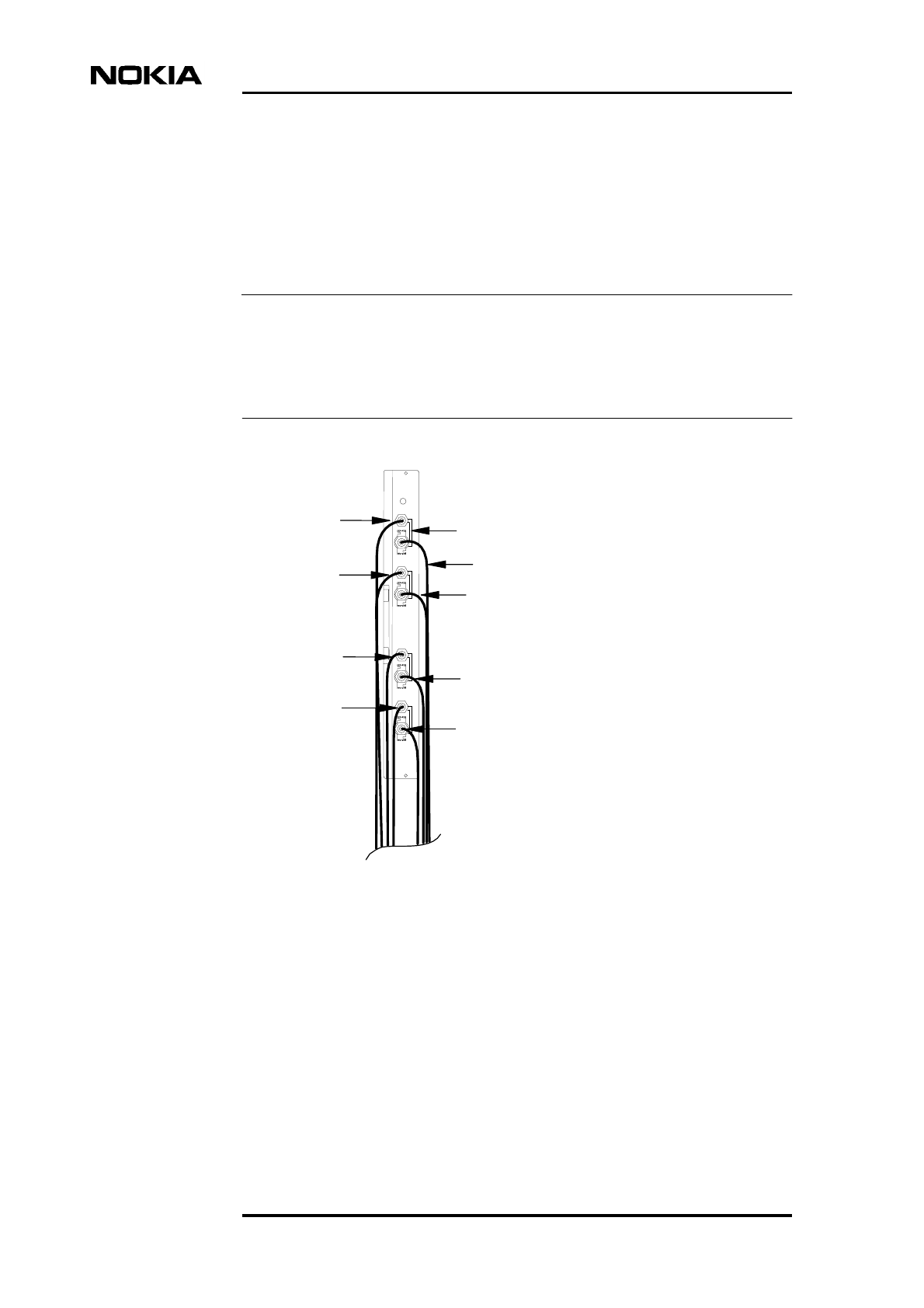
8.4.3 FXC E1/T1 transmission unit
FXC E1/T1 has four 100/120 Ω TX/RX connectors (type TQ).
Figure 22. Cabling of the FXC E1/T1 transmission unit
FXC E1/T1
RX/TX line 4
RX/TX line 3
RX/TX line 2
RX/TX line 1
Installation
62 (72) © Nokia Corporation DN991456
Nokia Proprietary and Confidential Issue 3 en
Cabling an FXC E1/T1 transmission unit
• Connect the connectors of the TX/RX signal lines to the 100/120 ΩTX/RX
connectors on the FXC E1/T1 front panel (see Figure 22). Tighten the
connector nut properly.
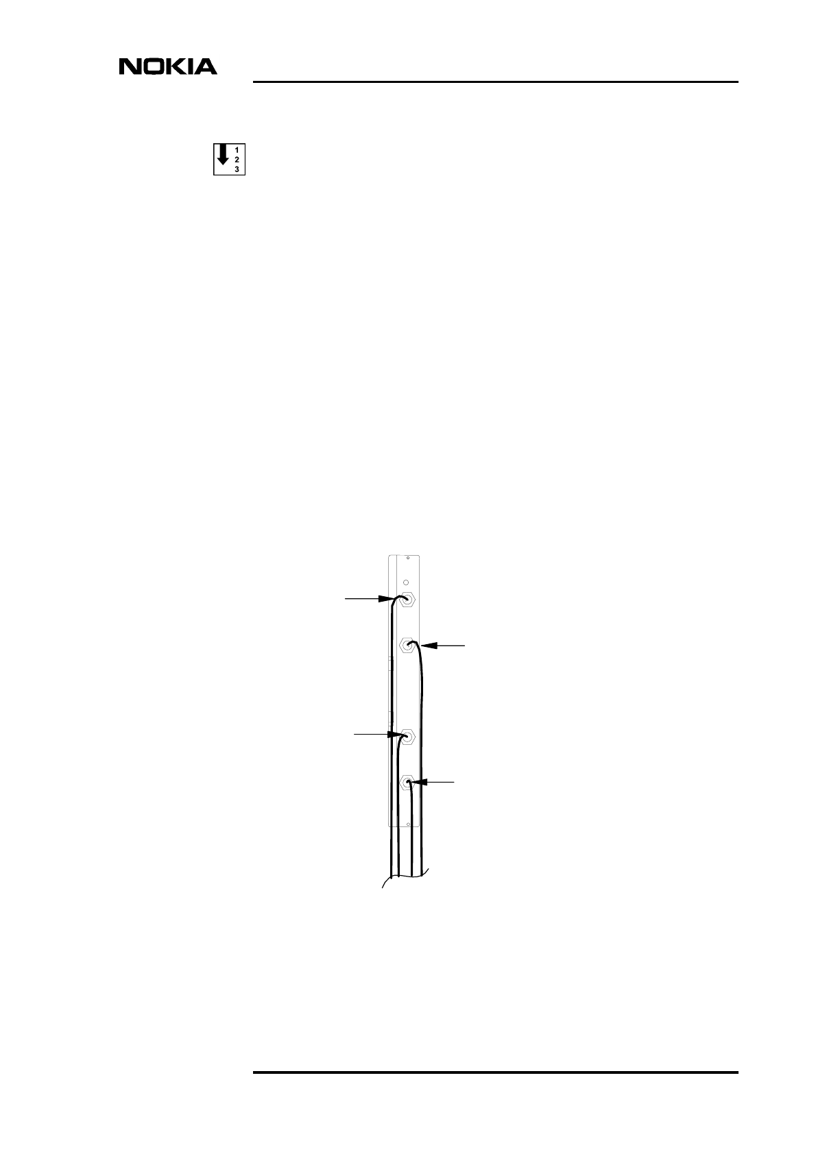
8.4.4 FXC RRI transmission unit
Figure 23. Cabling of the FXC RRI transmission unit
Cabling the FXC RRI transmission unit
• Connect the RX/TX (Flexbus) cable from the radio outdoor unit to the
TNC connector(s) on the FXC RRI transmission unit (see Figure 23).
RX/TX
(Flexbus)
radio 2
RX/TX
(Flexbus)
radio 1
FXC RRI
Cabinet cabling
DN991456 © Nokia Corporation 63 (72)
Issue 3 en Nokia Proprietary and Confidential
Note
8.5 Interface unit
Figure 24. Cabling of the interface unit
When you have connected the cables, push the rubber seals onto the connectors.
Cabling the interface unit
1. Connect the external alarms and controls cable to the EAC connector (26-
pin, mini-D connector).
EAC cable
LMP cable
(connect only
before
commissioning)
Q1 cable
Interface unit
Installation
64 (72) © Nokia Corporation DN991456
Nokia Proprietary and Confidential Issue 3 en
Note
Note
Caution
Note
2. Connect the Q1 cable to the Q1 connector (type TQ) on the interface unit.
Only connect the LMP cable from your MetroSite BTS Manager PC to the LMP
connector (BQ) just before starting the commissioning.
The extension interface connectors are not used yet.
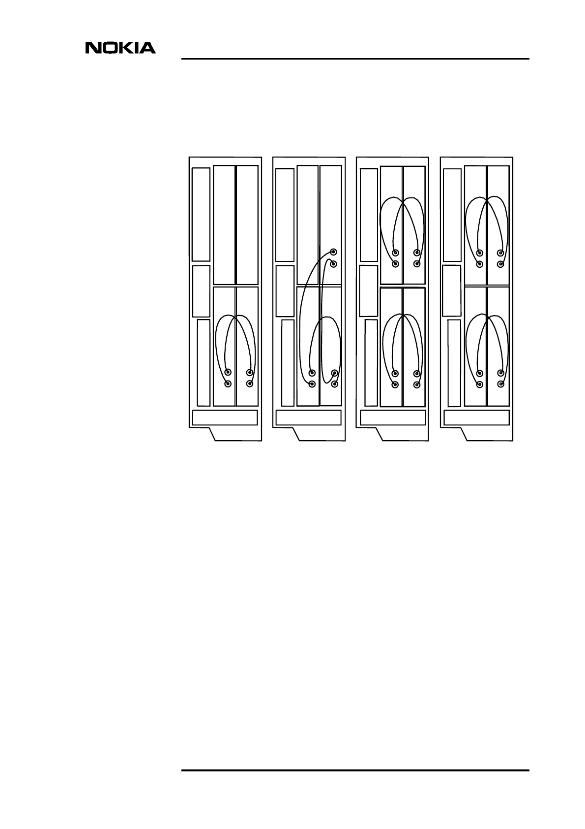
8.6 Transceiver units (TRXs)
Diversity cables and antenna feeders are connected to the TRXs. See also Nokia
MetroSite EDGE Base Station: Product Description.
Cabling the TRXs
1. Disconnect the diversity cables from the SMA type connectors on the
TRXs (if needed).
2. Reconnect the diversity cables to form the desired diversity configuration.
Examples of different sectoring alternatives and their diversity cabling are
presented in Figure 25.
Diversity cables may only be connected between TRXs that belong to the same
sector!
3. Connect the antenna feeders to the N-type connectors on the TRXs
according to the sectoring solution planned.
The diversity cabling solution is always dependent on the antenna solution.
Cabinet cabling
DN991456 © Nokia Corporation 65 (72)
Issue 3 en Nokia Proprietary and Confidential
4. Use a torque spanner/wrench for tightening the antenna diversity cables.
Tighten the SMA type connectors to 1 Nm (0.74 lb ft).
Figure 25. Examples of diversity cabling alternatives
2 TRX omni 3 TRX omni 2+2 TRX 4 TRX omni
DIV
OUT
DIV
OUT
DIV
IN
DIV
IN
T
R
X
1
T
R
X
2
DIV
IN
DIV
OUT
DIV
OUT
DIV
IN
DIV
OUT
DIV
IN
T
R
X
1
T
R
X
2
T
R
X
4
DIV
OUT
DIV
IN
DIV
IN
DIV
OUT
DIV
OUT
DIV
OUT
DIV
IN
DIV
IN
T
R
X
4
T
R
X
3
T
R
X
1
T
R
X
2
DIV
OUT
DIV
IN
DIV
IN
DIV
OUT
DIV
OUT
DIV
OUT
DIV
IN
DIV
IN
T
R
X
1
T
R
X
2
T
R
X
4
T
R
X
3
Possible antenna solutions
- 2 single port
antennas
- 1 dual port
antenna
- 1 dual port
and 1 single
port antenna
- 3 single port
antennas
- 2 dual port
antennas
- 4 single port
antennas
- 2 dual port
antennas
- 4 single port
antennas

Installation
66 (72) © Nokia Corporation DN991456
Nokia Proprietary and Confidential Issue 3 en
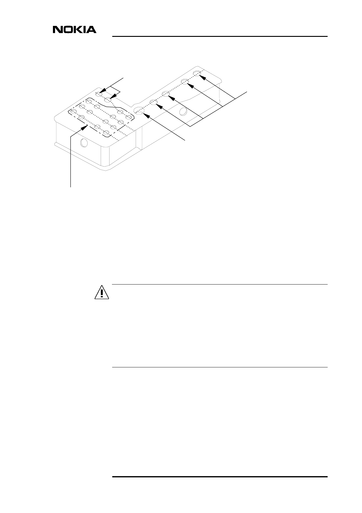
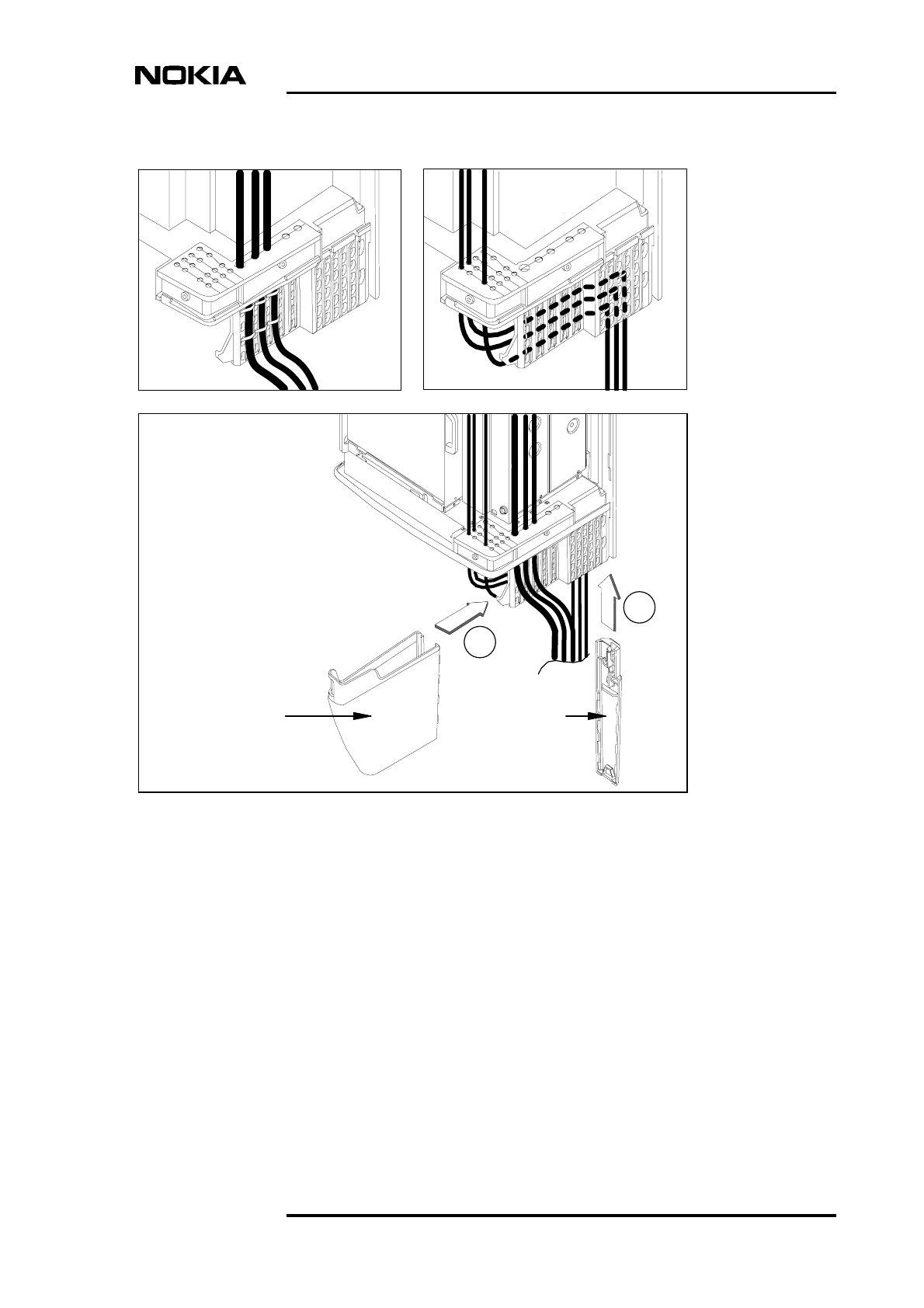
8.7 Completing the cabling
Completing the cabling procedure
1. Route the cables through the opened cable entry block, as presented earlier
in Figure 17.
2. Close the cable entry block with the two Allen screws. Use a torque driver
with a 4 mm Allen bit.
3. Replace the sealing strip around the cable entry block.
4. Route the antenna feeder cables and power supply cable to the front of the
perforated plastic panel (see [1] in Figure 26). Fix the cables to the
perforated panel with cable ties. Use side-cutting pliers to cut off the
extruding parts of the cable ties.
5. Route the transmission cables, the grounding cable and the cables coming
from the interface unit behind the perforated plastic panel at the lower edge
of the BTS (see [2] in Figure 26). Fix the cables to the perforated panel with
at least two cable ties. Use side-cutting pliers to cut off the extruding parts
of the cable ties.
6. Attach the cable cover support on the grips at the far end of the perforated
panel (see [A] in Figure 26).
7. Push the cables towards the cable cover support at the far end of the
perforated panel.
8. Place the cable cover onto the hook at the near end of the perforated panel.
Align it to the recesses on the cable cover support and slide it downwards
until it locks to the cable cover support (see [B] in Figure 26).
Cabinet cabling
DN991456 © Nokia Corporation 67 (72)
Issue 3 en Nokia Proprietary and Confidential
Figure 26. Routing the cables and closing the cable cover
A
B
Cable cover Cable cover
support

Installation
68 (72) © Nokia Corporation DN991456
Nokia Proprietary and Confidential Issue 3 en
Completing the installation
DN991456 © Nokia Corporation 69 (72)
Issue 3 en Nokia Proprietary and Confidential
9Completing the installation
With the BTS safely fixed to a wall or a pole, commissioning can be started.
Commissioning can be left to a later stage if there are no qualified personnel on
the site during installation. To complete the installation, the BTS cover is fitted to
the chassis and the BTS cabinet is locked.
Commissioning the BTS
1. Switch the BTS power ON.
2. Connect the LMP cable from the MetroSite BTS Manager PC to the LMP
connector on the interface unit.
3. Proceed to the BTS commissioning tasks. Refer to Nokia MetroSite EDGE
Base Station: Commissioning.
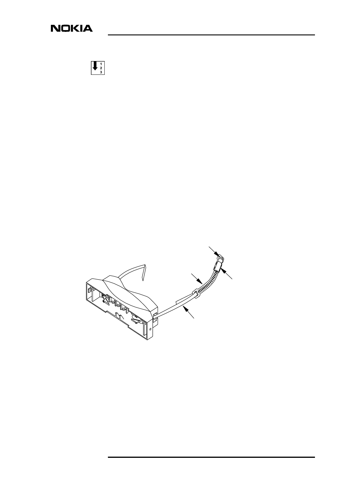
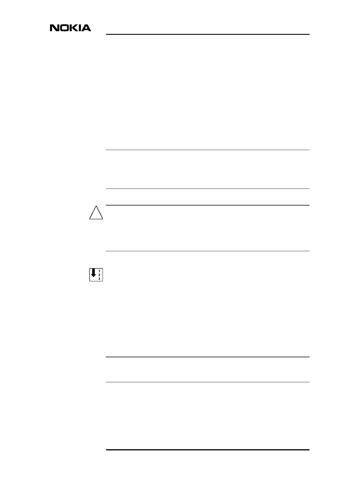
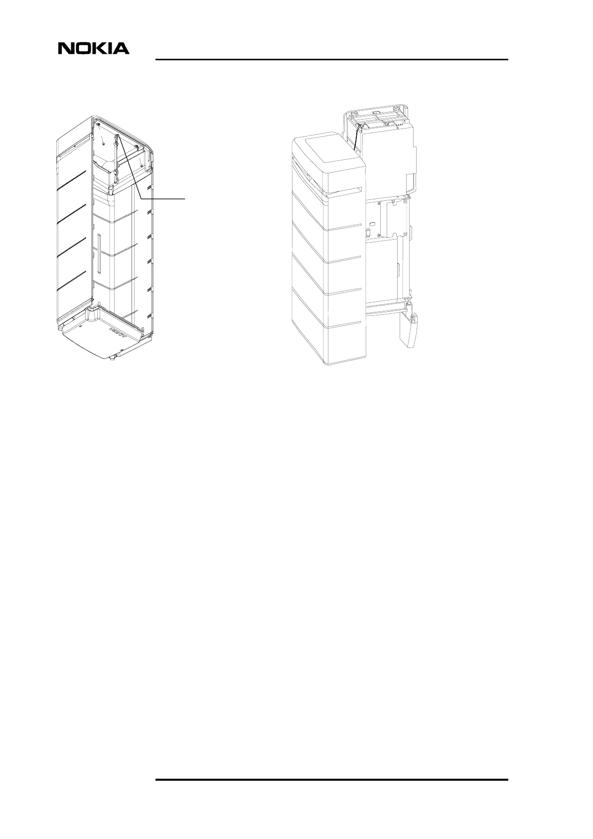
Fitting the cover and locking the cabinet
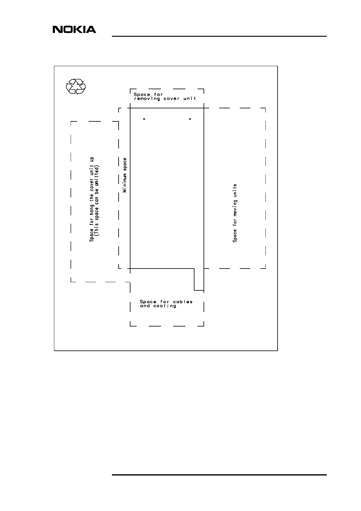
1. Bring the BTS cover to the BTS chassis (see Figure 27). Attach the safety
strap to the fixing point provided under the top of the cover.
2. Make sure that the cover is secured with the safety strap (see Figure 27).
3. Place the cover over the cabinet and align the locking hooks on the cover
to the locking rail on the chassis. Push the cover into the chassis and pull
downwards to lock the hooks firmly into the rail.
4. Check that the cover is firmly secured by pushing the cover from the sides.
5. Lock the cabinet with the key.
6. Clean the site. Recycle any applicable material.
Installation
70 (72) © Nokia Corporation DN991456
Nokia Proprietary and Confidential Issue 3 en
Figure 27. Hanging the BTS cover
Fixing point
for safety strap
under the
cover top

DN991456 ©Nokia Corporation 71 (72)
Issue 3 en Nokia Proprietary and Confidential
Index
A
AC power warnings 55
antenna solutions 64
antistatic wrist strap 25,49
assembling pole brackets 36,43
B
band length for pole mounting 41,43
bracket blocks for pole mounting
back block 35
front block 35
C
cabinet installation 29
cable cover 66
cable entry block 52
cables
antenna feeders 52
extension 52
external alarms and controls 52
grounding 52
power supply 52
transmission 52
cabling
antenna feeders 64
diversity cables 64
grounding 53
interface unit 63
power supply 55
transmission unit 58
TRX unit 64
capacitive grounding 58
cardboard template 30
commissioning 69
completing the cabling 66
cover 69
D
DC power 56
delivery contents 21
dimensions
mounting rack 30
pole diameter 35
wall space 32
direct grounding 58
diversity cabling alternatives 64
E
EAC connector 63
electro-static discharge (ESD) protection 25,49
F
FC E1/T1 58
FXC E1 60
FXC E1/T1 61
FXC RRI 62
G
grounding 53
grounding bridge 58
I
installing
BTS onto a pole 37
BTS onto a wall 32
BTS onto the mounting rack 38,46
cabinet 29
mounting rack onto a pole 44
pole brackets onto a pole 44
units 49
interface unit
cabling 63
K
key for BTS cabinet lock 20
L
L-beam 34
LMP connector 64
locking device 43
M
mounting kit 35
mounting kit for pole mounting 41
mounting rack 29,34
mounting rack installation 37,44
O
offset screws 34

Installation
72 (72) © Nokia Corporation DN991456
Nokia Proprietary and Confidential Issue 3 en
P
parts for installation 16,30
pole bracket assembly 36,43
pole bracket installation 44
pole diameter 35,41,43
pole mounting 34
pole mounting kit 22
power supply connectors 56
power supply unit
cabling 55
preparations
cabling 51
Q
Q1 connector 64
R
removing units 25
S
safety strap 69
sealing strip 51
sectoring solutions 64
shield units 21,25,49
site requirements 15
SMA type connectors 64
T
template for wall mounting 30
tools for installation 16
transceiver unit (TRX)
cabling 64
transmission unit
cabling 58
transportation package 19
U
unit installation 49
unit removal 25
unpacking the delivery 19
W
wall mounting 32