Nokia Solutions and Networks WTFA-01 GSM 800 Transciever User Manual dn991456x3x0xen
Nokia Solutions and Networks GSM 800 Transciever dn991456x3x0xen
UserManual.wiki
>
Nokia Solutions and Networks
>
WTFA-01 User Manual
>
Installation
Contents
1.
Alarm Desc
2.
Commissioning
3.
Field Upgrade
4.
Glossary
5.
Guide to documentation
6.
Maintenance
7.
Product Desc
8.
Installation requirements
9.
Solution Accessories
10.
Warnings and cautions
11.
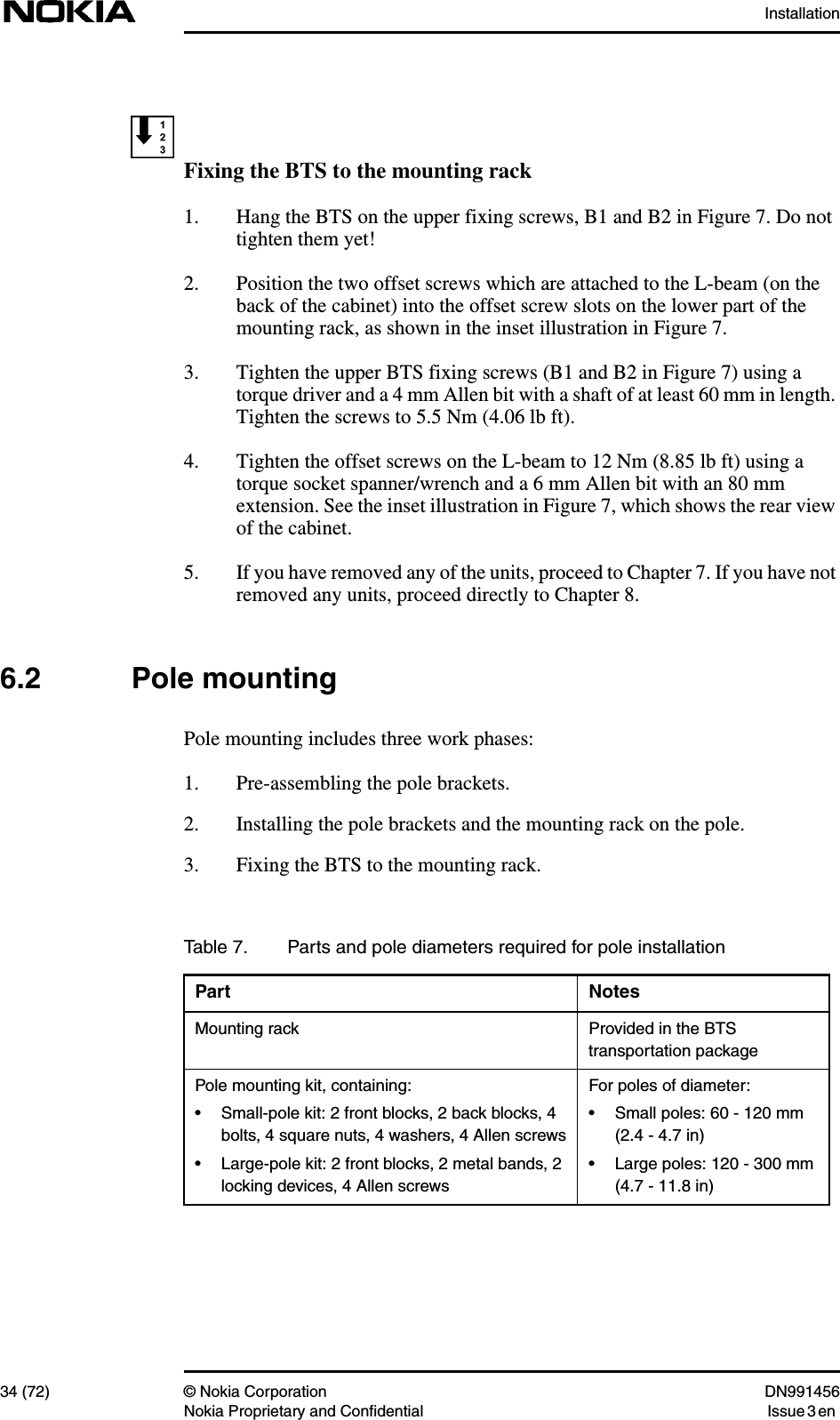
Installation
Installation
Navigation menu
Upload a User Manual
Namespaces
Wiki Guide
HTML
PDF
Info
Views
User Manual
Discussion / Help
Navigation
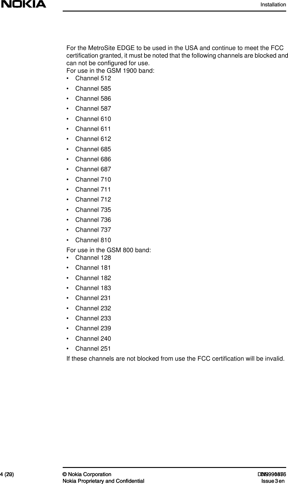


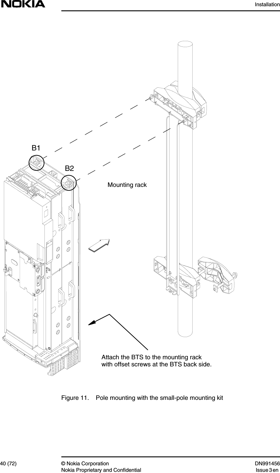
![Installation36 (72) © Nokia Corporation DN991456Nokia Proprietary and Confidential Issue 3 enPre-assembling the pole brackets1. Insert the M8 assembly bolts and washers into the bolt holes in the backblocks. See [1] in Figure 9.2. Attach the square nuts on the ends of the bolts. Screw on the nuts justenough to secure them on the ends of the bolts. See [2] in Figure 9.3. Slide one of the bolts with the square nut into the slot at the side of the frontblock. See [3] in Figure 9.4. Screw the bolt in further, enough to prevent the bolt and the square nutfrom sliding out from the front block. See [4] in Figure 9.Figure 9. Pre-assembling the pole brackets1324](https://usermanual.wiki/Nokia-Solutions-and-Networks/WTFA-01.Installation/User-Guide-303293-Page-36.png)
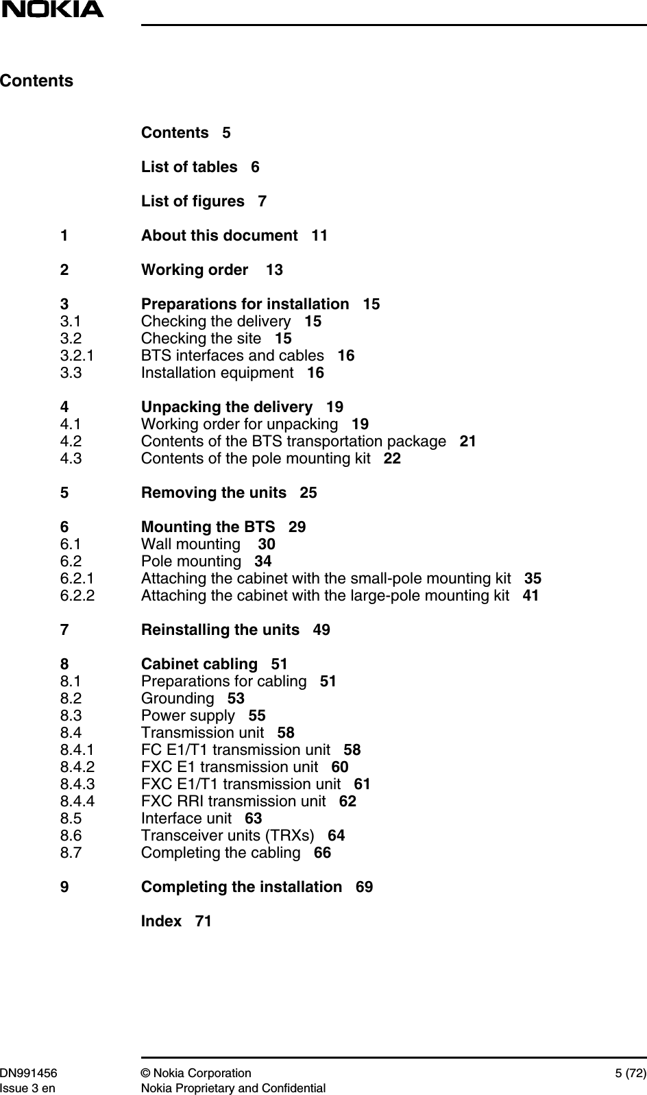
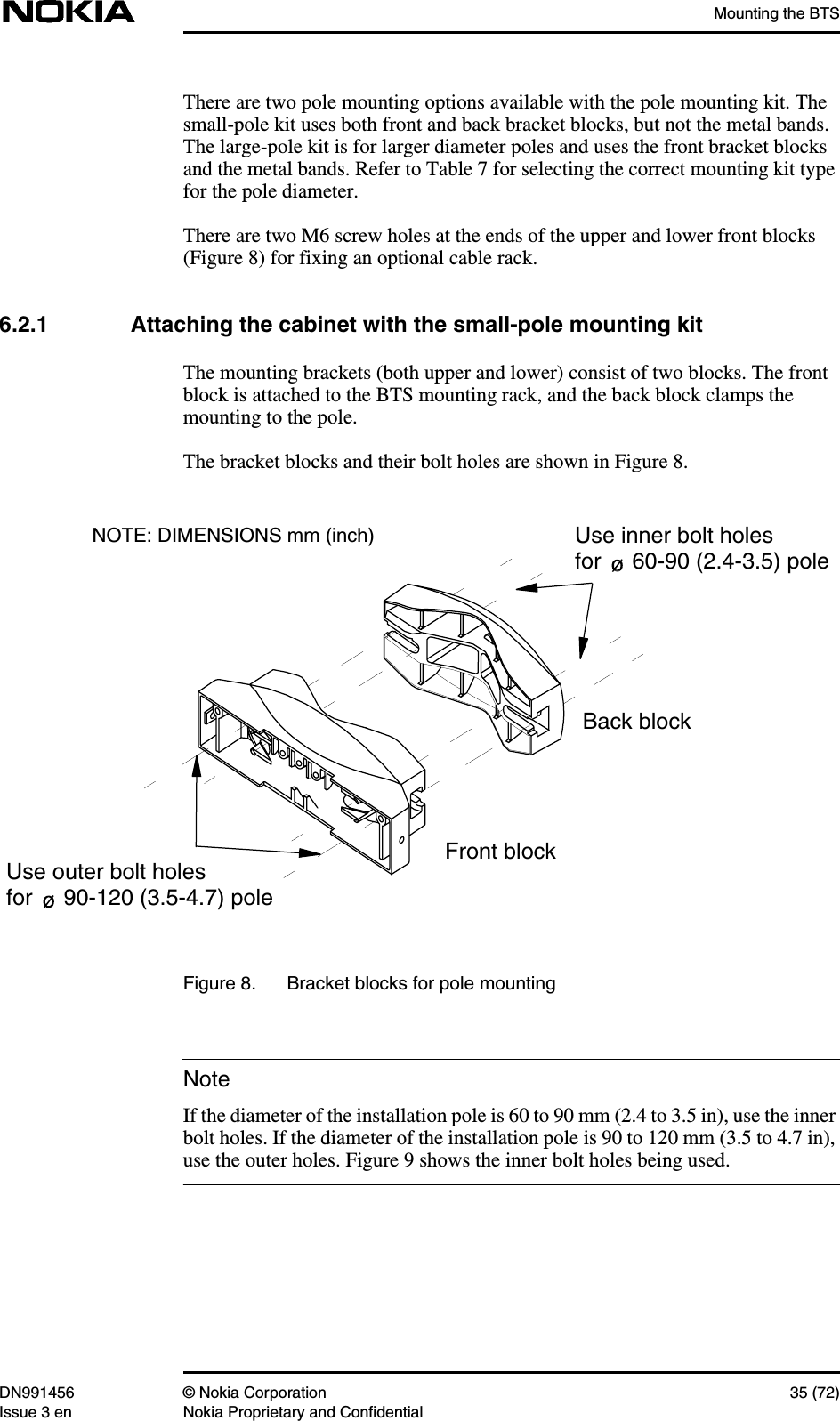
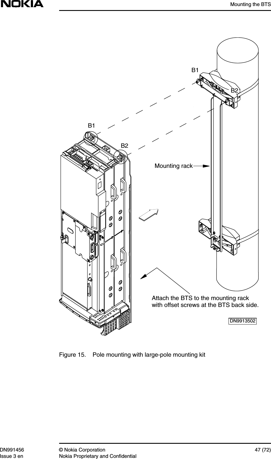
![Mounting the BTSDN991456 © Nokia Corporation 41 (72)Issue 3 en Nokia Proprietary and Confidential6.2.2 Attaching the cabinet with the large-pole mounting kitWith the large-pole mounting kit, the front bracket blocks are clamped to the polewith a metal band and locking device.There are two types of band and locking device. One uses grooved metal bands,as described in procedure [A] below. The other type of locking device usessmooth bands and a locking rack, as described in procedure [B] below. Follow theprocedure for the type of locking device and band in your kit.[A] Pre-assembling the pole brackets and bands (grooved band type)1. Assemble the locking device and band by inserting the end of the metalband approximately 25 mm (1 in.) into the locking device. The correct setup of the parts is shown in Figure 12.Bend the surplus end of the metal band underneath the locking device, asshown in [3] [A] in Figure 12.Flatten the bent-over end of the metal band to remove any distortion.The locking device is now assembled.2. Cut the metal band to the appropriate length, according to the polediameter. Refer to Table 8 below.Table 8. Band length for different pole diametersPole diameter(mm)Band length(mm)Pole diameter(in)Band length(in)140 580 5.5 22.8160 630 6.3 24.8180 680 7.1 26.8200 740 7.9 29.1220 790 8.7 31.1240 850 9.5 33.5260 900 10.2 35.4280 950 11.0 37.4300 1010 11.8 39.8](https://usermanual.wiki/Nokia-Solutions-and-Networks/WTFA-01.Installation/User-Guide-303293-Page-41.png)
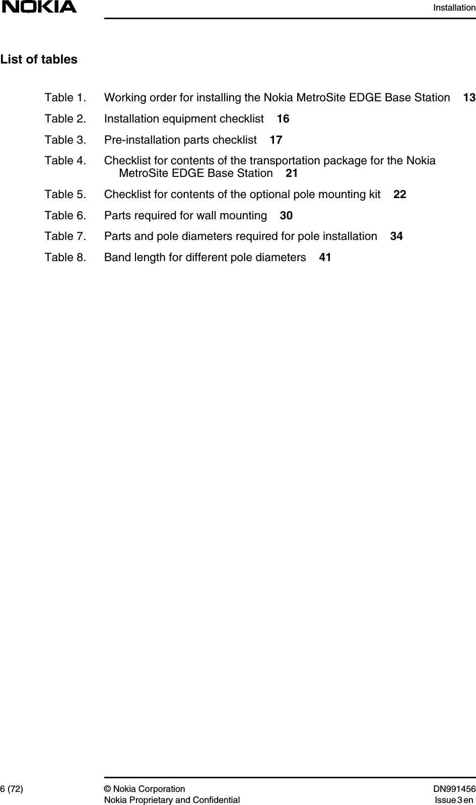
![Installation42 (72) © Nokia Corporation DN991456Nokia Proprietary and Confidential Issue 3 en3. Route the metal band through the holes in the front block, as shown in [4],Figure 12.Leave the other end of the metal band free until you have completed thenext procedure (fixing the front bracket blocks to the mounting rack).Legend:1 Metal band2 Locking device3 Detail of locking device, attached to metal band4 Detail of entry point for metal band into front bracket blockFigure 12. Pole bracket pre-assembled (large-pole mounting kit)1DN02454342AB34](https://usermanual.wiki/Nokia-Solutions-and-Networks/WTFA-01.Installation/User-Guide-303293-Page-42.png)
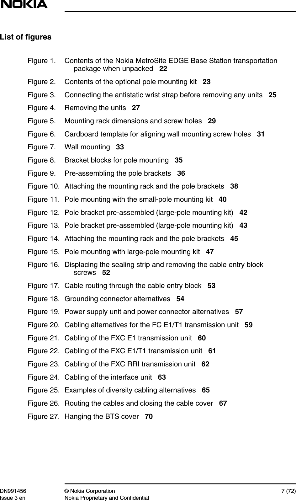
![Mounting the BTSDN991456 © Nokia Corporation 43 (72)Issue 3 en Nokia Proprietary and Confidential[B] Pre-assembling the pole brackets and bands (non-grooved bandtype)1. Assemble the locking device by inserting the end of the locking rack intothe worm screw housing and turning the screw to engage the rack. Makesure you have the rack the right way round when doing this. The words‘THIS SIDE UP’ should be visible on the rack when the locking device isclamped around the pole. Refer to Figure 12.2. Cut the metal band to the appropriate length, according to the polediameter. Refer to Table 8 above.3. Route the metal band through the holes in the front block.4. Bend one end of the metal band over to form a hook of about 30 mm (1.2in) in length.5. Insert the hook into the slot at the end of the locking rack.6. Bend the other end of the metal band over to form another hook of about30 mm (1.2 in) in length. Leave it free for now.Figure 13. Pole bracket pre-assembled (large-pole mounting kit)LockingrackMetalbandWorm screwhousingWorm screw](https://usermanual.wiki/Nokia-Solutions-and-Networks/WTFA-01.Installation/User-Guide-303293-Page-43.png)
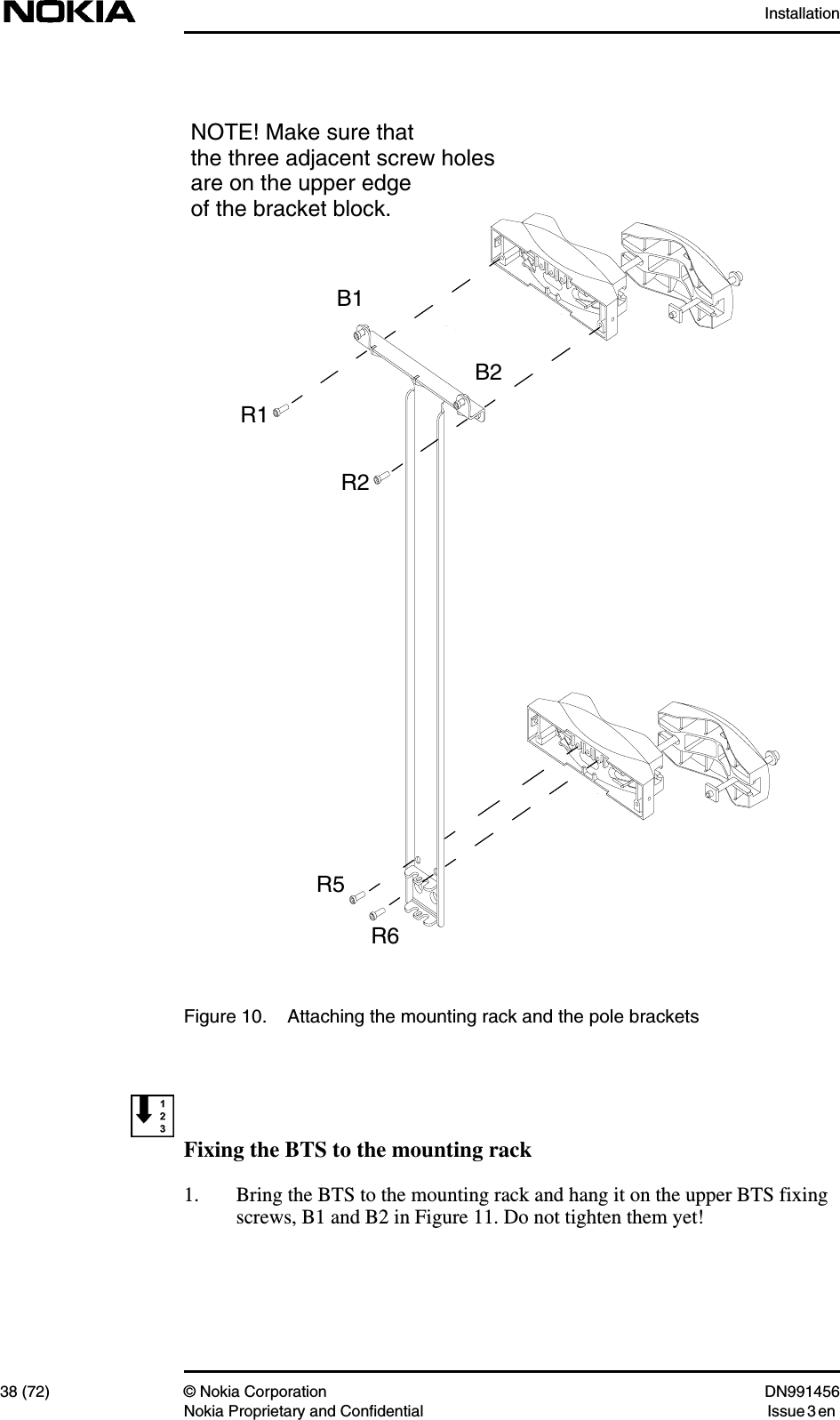
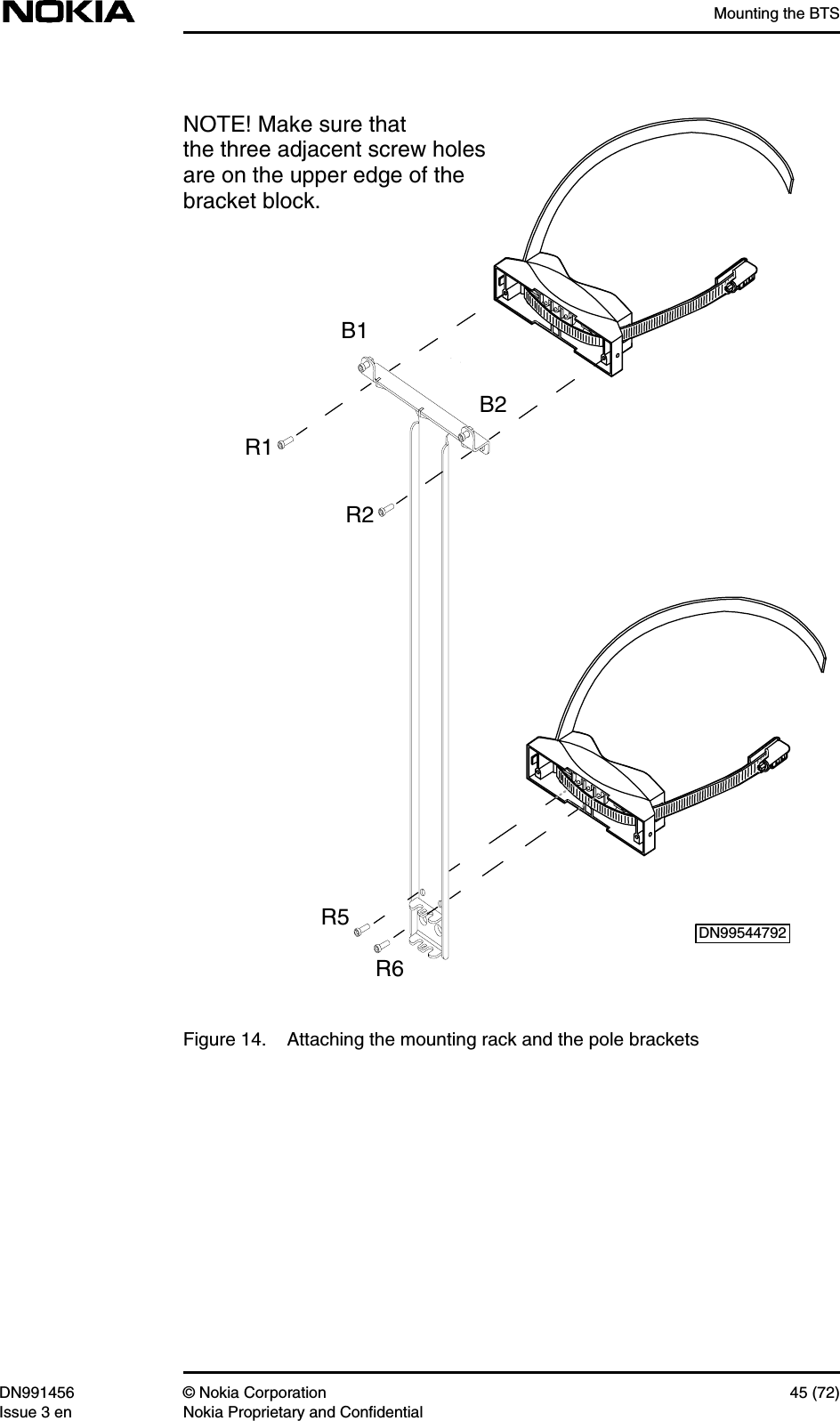
![Installation44 (72) © Nokia Corporation DN991456Nokia Proprietary and Confidential Issue 3 enNoteFixing the pole bracket and the mounting rack to a poleBefore taking the mounting rack up the pole, perform the tasks instructed in Steps1 and 2 below.1. Fix the upper pole bracket to the mounting rack by screwing the M6 x 20Allen screws through R1 and R2 into the upper front block, as shown inFigure 14. Make sure that the front block is the correct way up (the set ofthree adjacent screw holes should be on the upper edge of the bracket). Usea torque driver with a 4 mm Allen bit to tighten the screws to 5.5 Nm (4.06lb ft).2. Fix the lower pole bracket to the mounting rack by screwing the M6 x 20Allen screws through R5 and R6 into the lower block, as shown in Figure14. Make sure that the set of three adjacent screw holes is on the upper edgeof the bracket. Use a torque driver with a 4 mm Allen bit to tighten thescrews to 5.5 Nm (4.06 lb ft).3. Take the mounting rack/pole bracket combination to the pole.4. Wrap the metal band of the upper bracket around the pole.5. Insert the free end of the metal band (grooved type) into the slot on theworm screw housing, as shown in [B] of Figure 12. Wind the metal bandinto the locking device by turning the nut with a flat screwdriver or 8 mmhexagon socket and wrench.ORInsert the hook-shaped free end of the band (non-grooved type) into the sloton the worm screw housing. Tighten the worm screw using a flatscrewdriver or 8 mm hexagon socket and wrench.6. When all the slack on the band has been wound in with the locking device,tighten the worm screw to 10 Nm (7.4 lb ft) using a torque socketspanner/wrench and the 8 mm hexagon socket.7. Fix the lower bracket in the same manner as the upper bracket.](https://usermanual.wiki/Nokia-Solutions-and-Networks/WTFA-01.Installation/User-Guide-303293-Page-44.png)

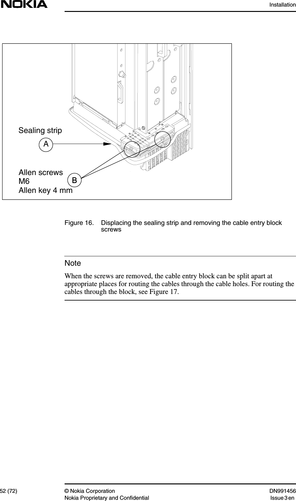
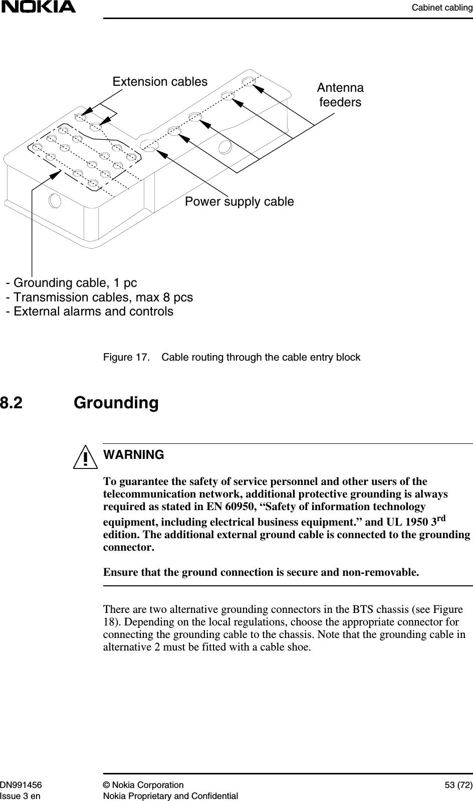
![Cabinet cablingDN991456 © Nokia Corporation 51 (72)Issue 3 en Nokia Proprietary and ConfidentialNote8Cabinet cablingThis document assumes that you are using the ready-made cables supplied byNokia, or that all cables have been prefabricated before starting the cabling of theBTS. For information on the cable types and connectors refer to Nokia MetroSiteEDGE Base Station: Requirements for Installation and Operation. For the pinconfigurations refer to Nokia MetroSite EDGE Base Station: ProductDescription.The connectors on the units’ front panels are protected with rubber caps. Removethe caps only from those connectors that will be used for BTS cabling.8.1 Preparations for cablingBefore starting the cabling, do the following:1. Displace the sealing strip around the cable entry block. See [A] in Figure16.2. Loosen and remove the two Allen screws that keep the cable entry block inplace. Use a torque driver with a 4 mm Allen bit. For the location of thescrews, see [B] in Figure 16.](https://usermanual.wiki/Nokia-Solutions-and-Networks/WTFA-01.Installation/User-Guide-303293-Page-51.png)
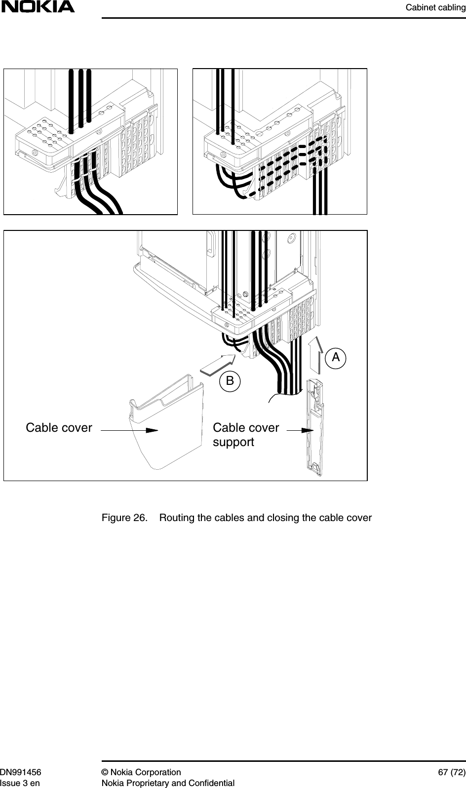
![Installation66 (72) © Nokia Corporation DN991456Nokia Proprietary and Confidential Issue 3 en8.7 Completing the cablingCompleting the cabling procedure1. Route the cables through the opened cable entry block, as presented earlierin Figure 17.2. Close the cable entry block with the two Allen screws. Use a torque driverwith a 4 mm Allen bit.3. Replace the sealing strip around the cable entry block.4. Route the antenna feeder cables and power supply cable to the front of theperforated plastic panel (see [1] in Figure 26). Fix the cables to theperforated panel with cable ties. Use side-cutting pliers to cut off theextruding parts of the cable ties.5. Route the transmission cables, the grounding cable and the cables comingfrom the interface unit behind the perforated plastic panel at the lower edgeof the BTS (see [2] in Figure 26). Fix the cables to the perforated panel withat least two cable ties. Use side-cutting pliers to cut off the extruding partsof the cable ties.6. Attach the cable cover support on the grips at the far end of the perforatedpanel (see [A] in Figure 26).7. Push the cables towards the cable cover support at the far end of theperforated panel.8. Place the cable cover onto the hook at the near end of the perforated panel.Align it to the recesses on the cable cover support and slide it downwardsuntil it locks to the cable cover support (see [B] in Figure 26).](https://usermanual.wiki/Nokia-Solutions-and-Networks/WTFA-01.Installation/User-Guide-303293-Page-66.png)