Nokia Solutions and Networks WTFA-01 GSM 800 Transciever User Manual dn991444x3x0xen
Nokia Solutions and Networks GSM 800 Transciever dn991444x3x0xen
UserManual.wiki
>
Nokia Solutions and Networks
>
WTFA-01 User Manual
>
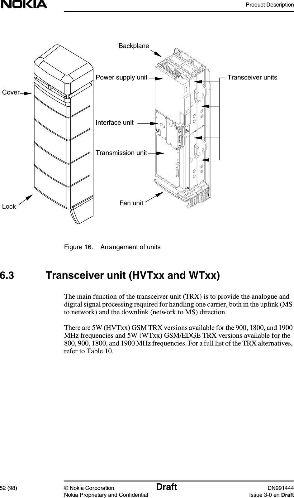
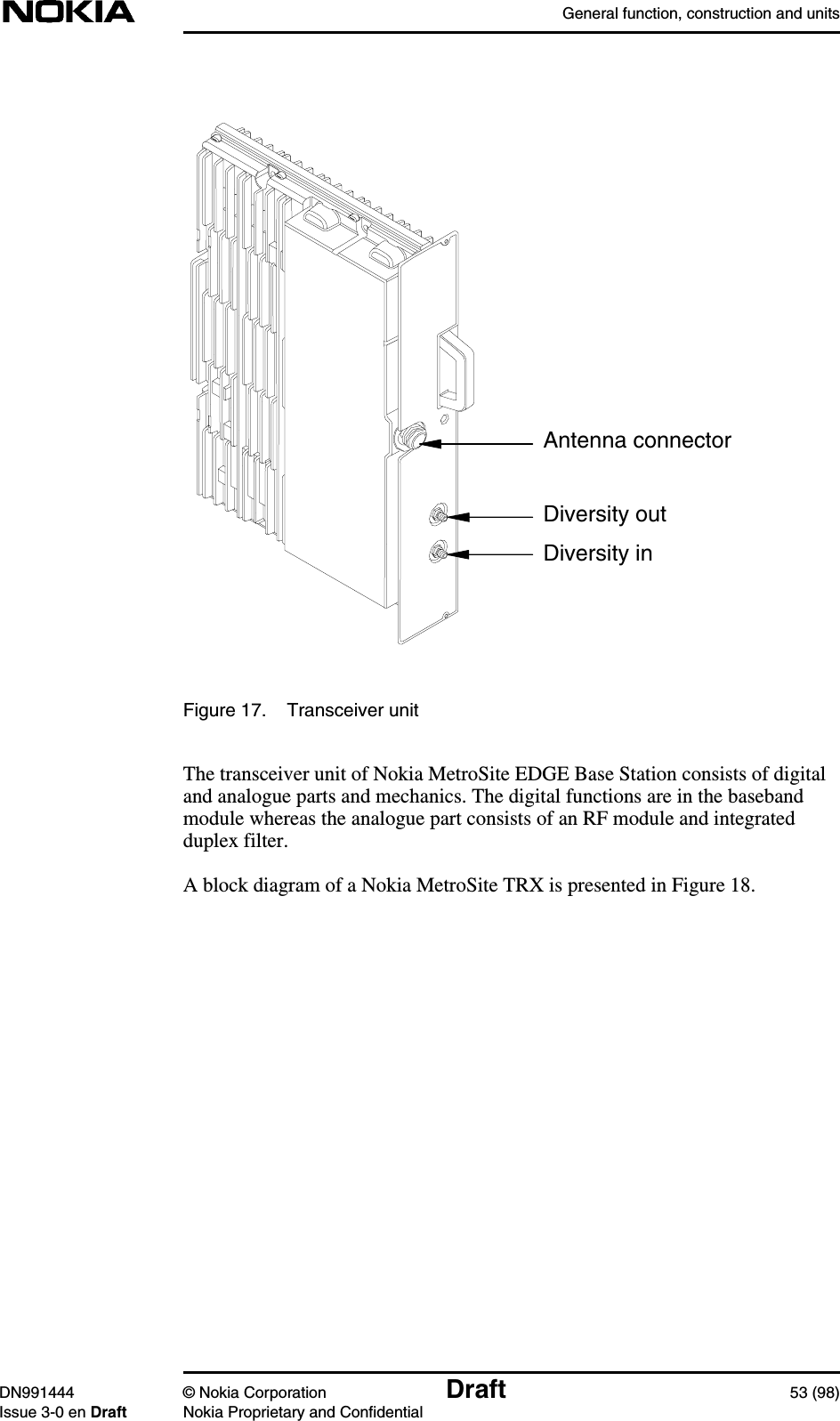
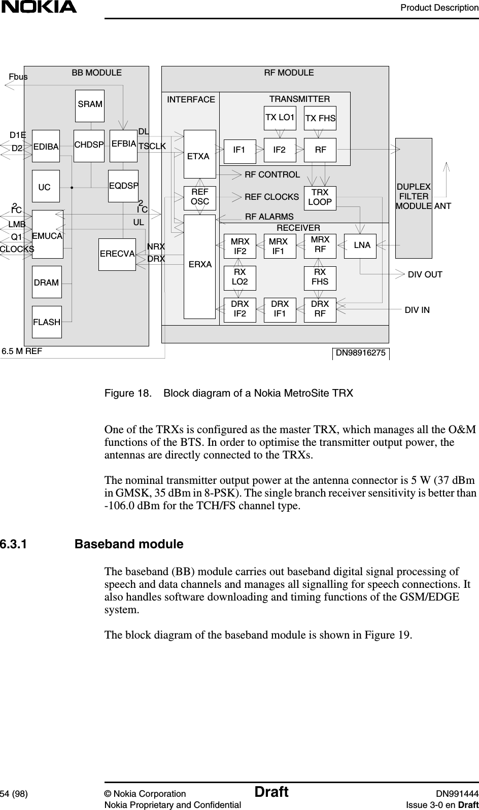
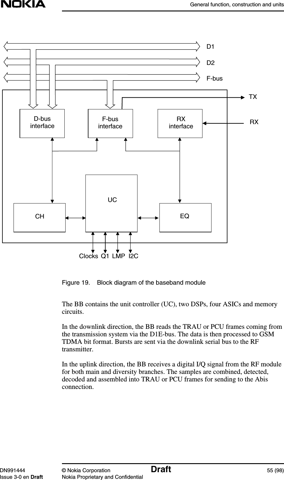
Product Desc
Contents
1.
Alarm Desc
2.
Commissioning
3.
Field Upgrade
4.
Glossary
5.
Guide to documentation
6.
Maintenance
7.
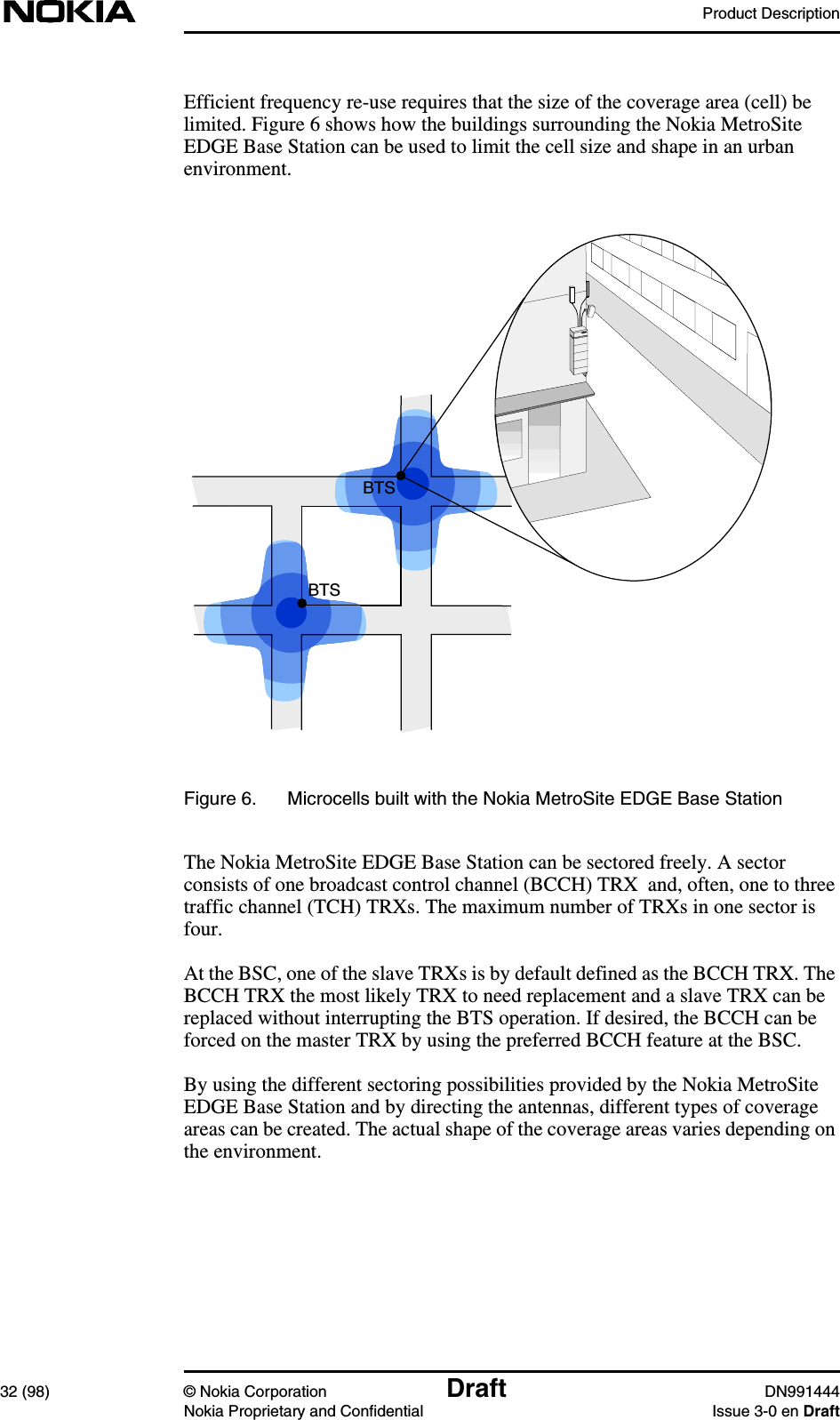
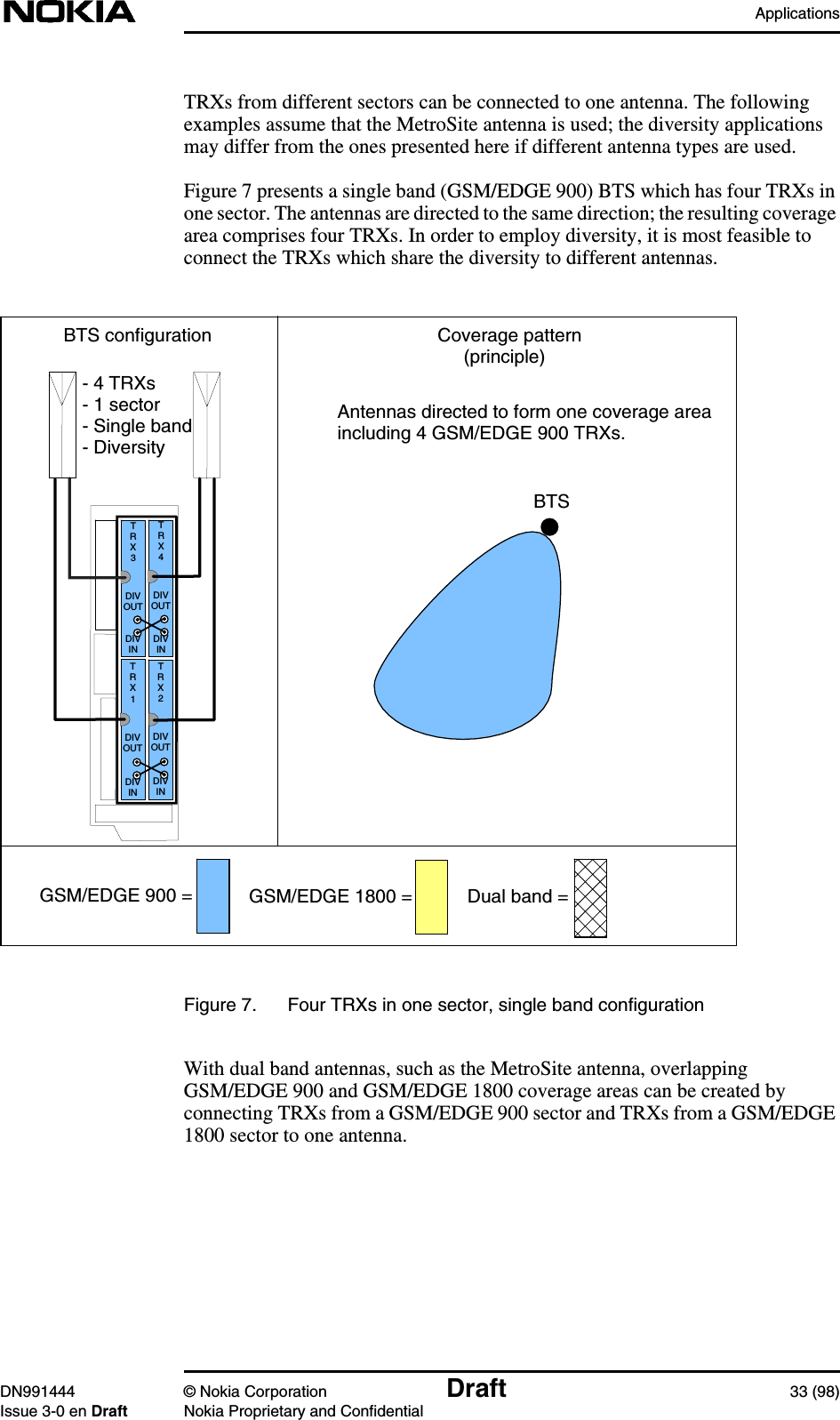
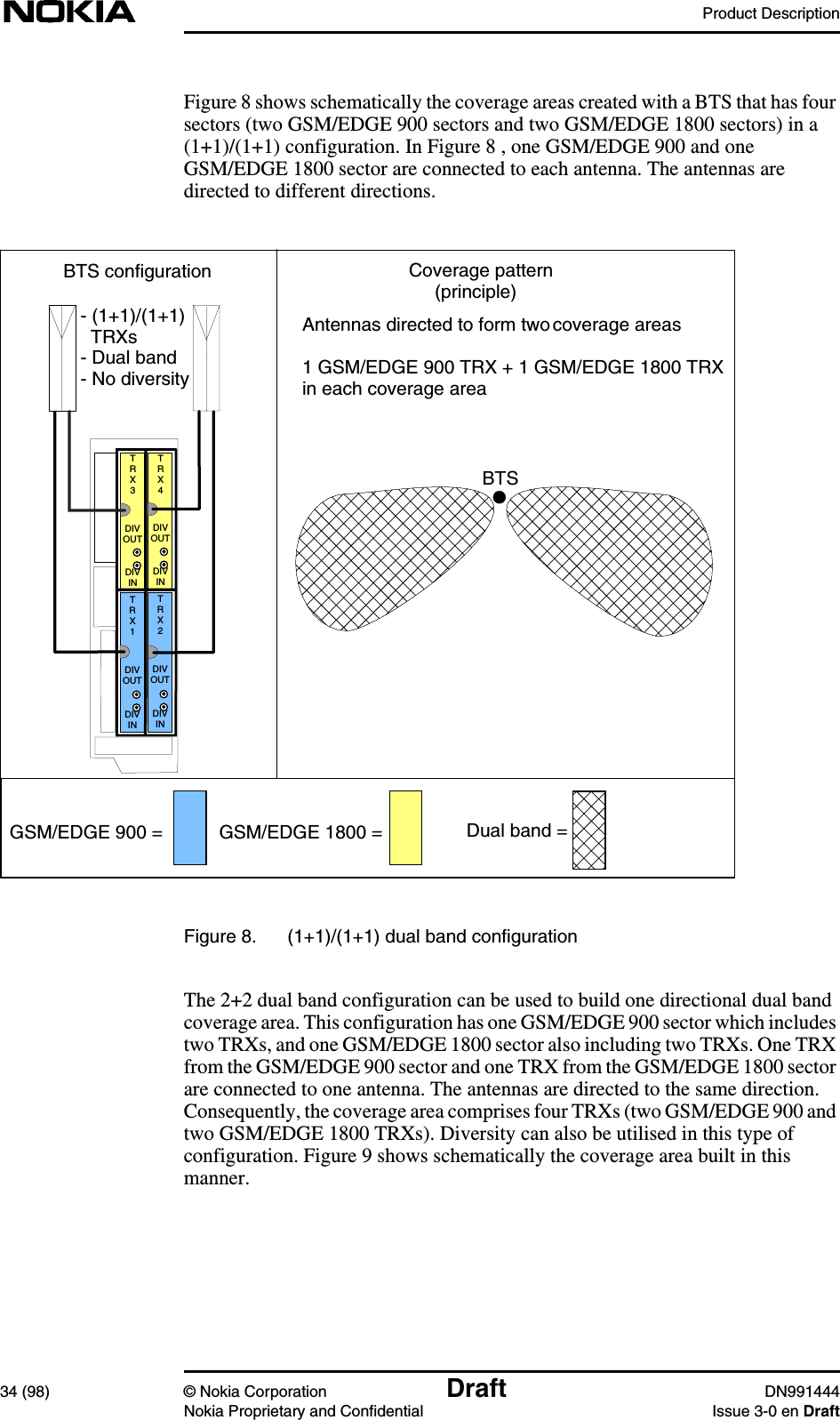
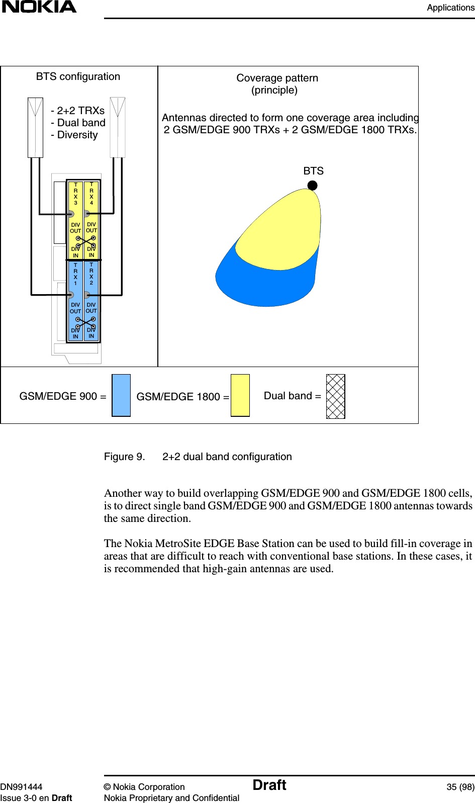
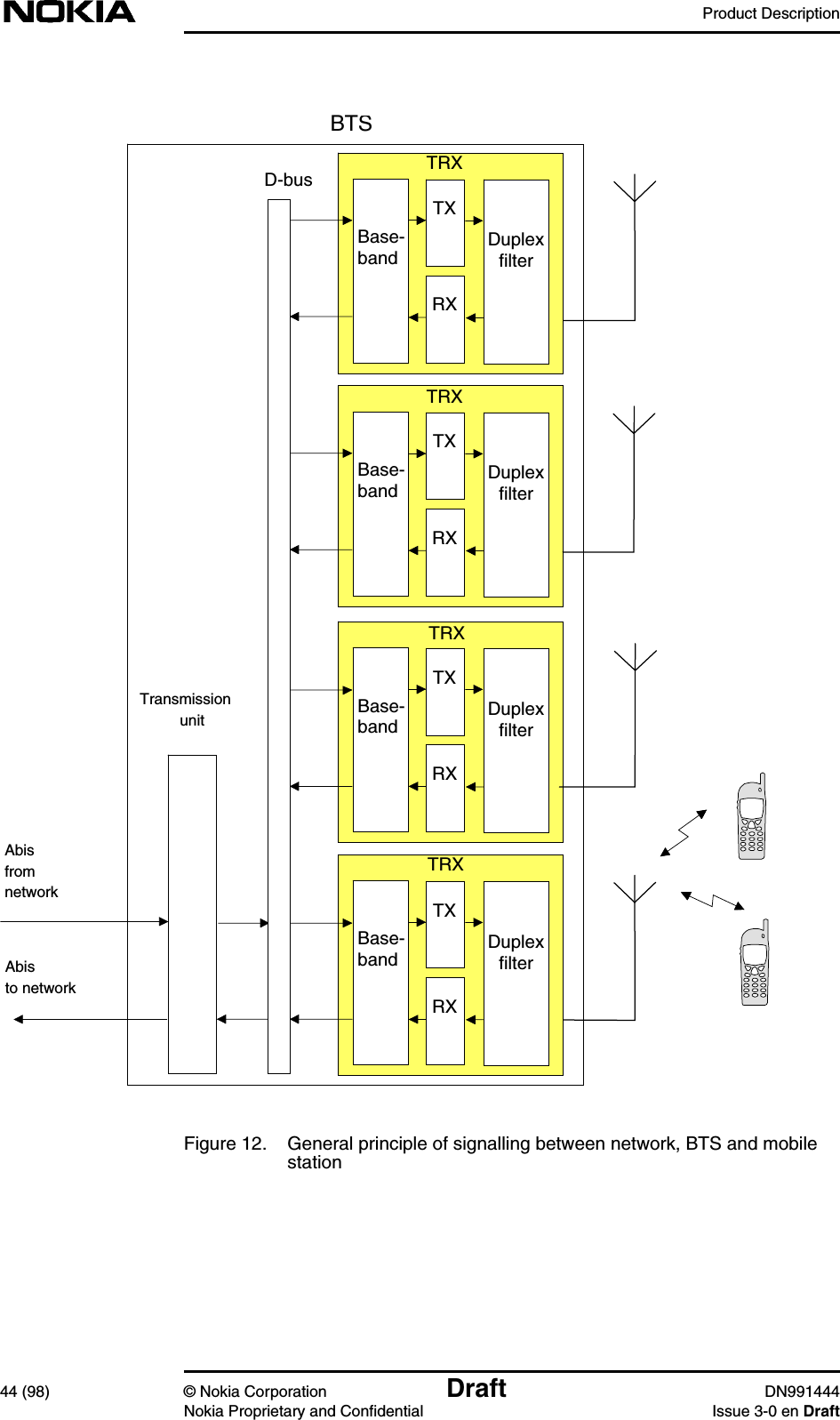
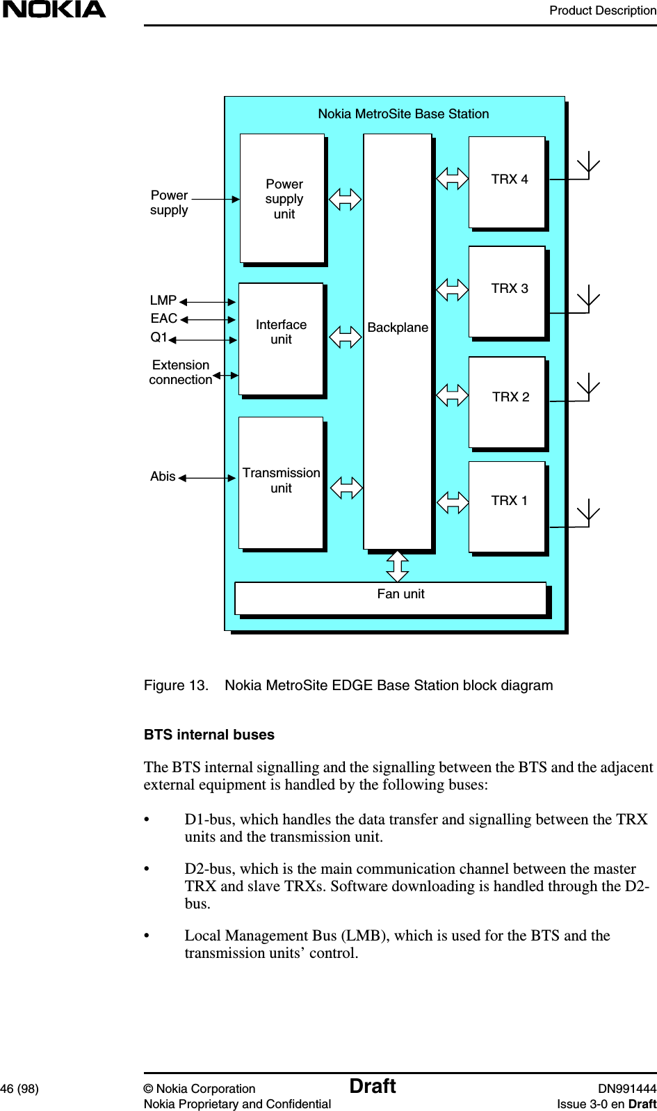
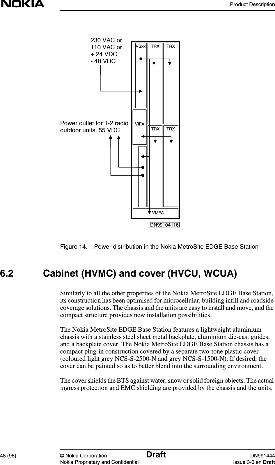
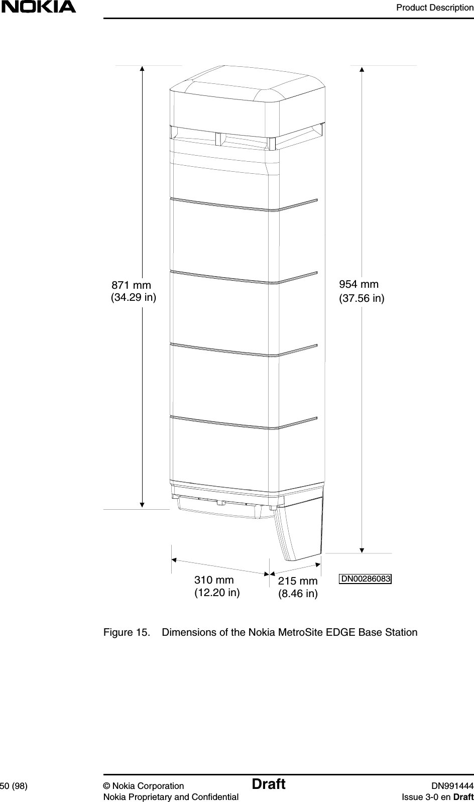
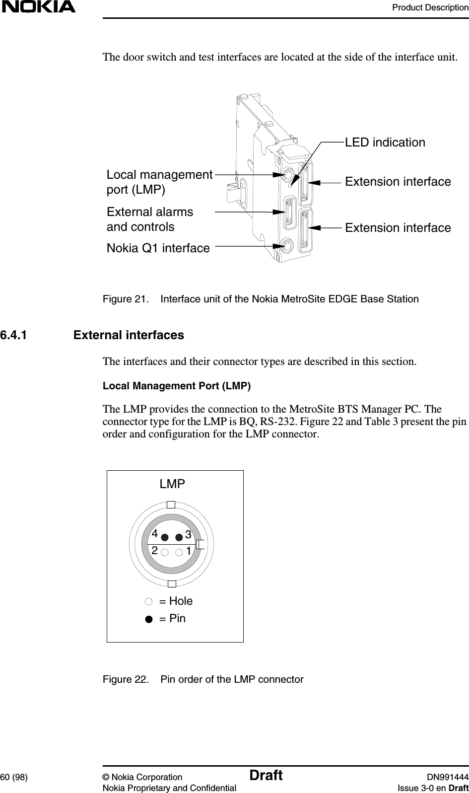
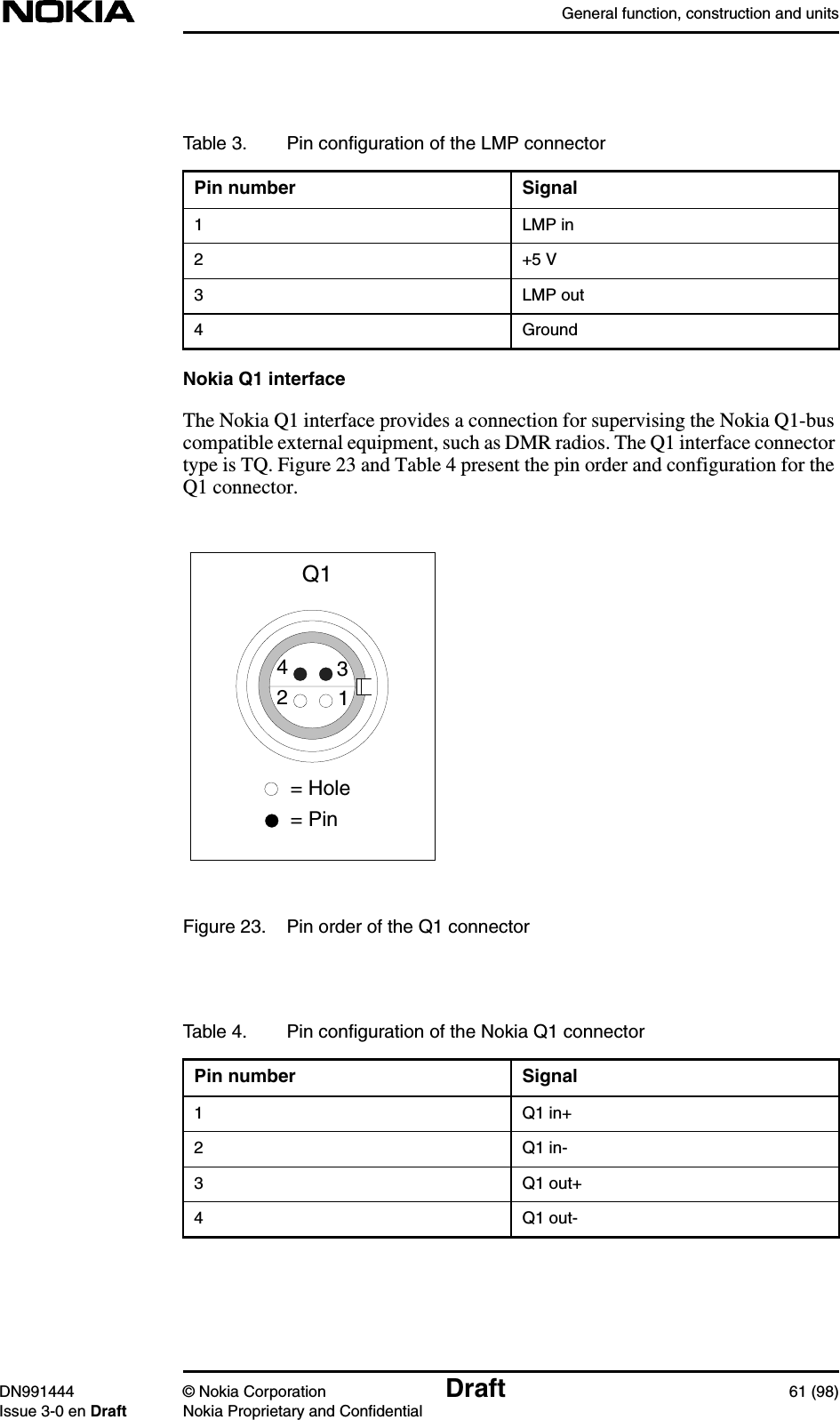
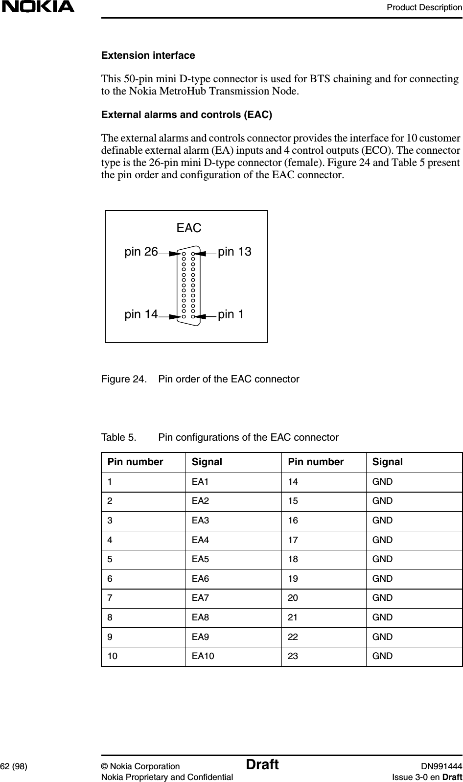
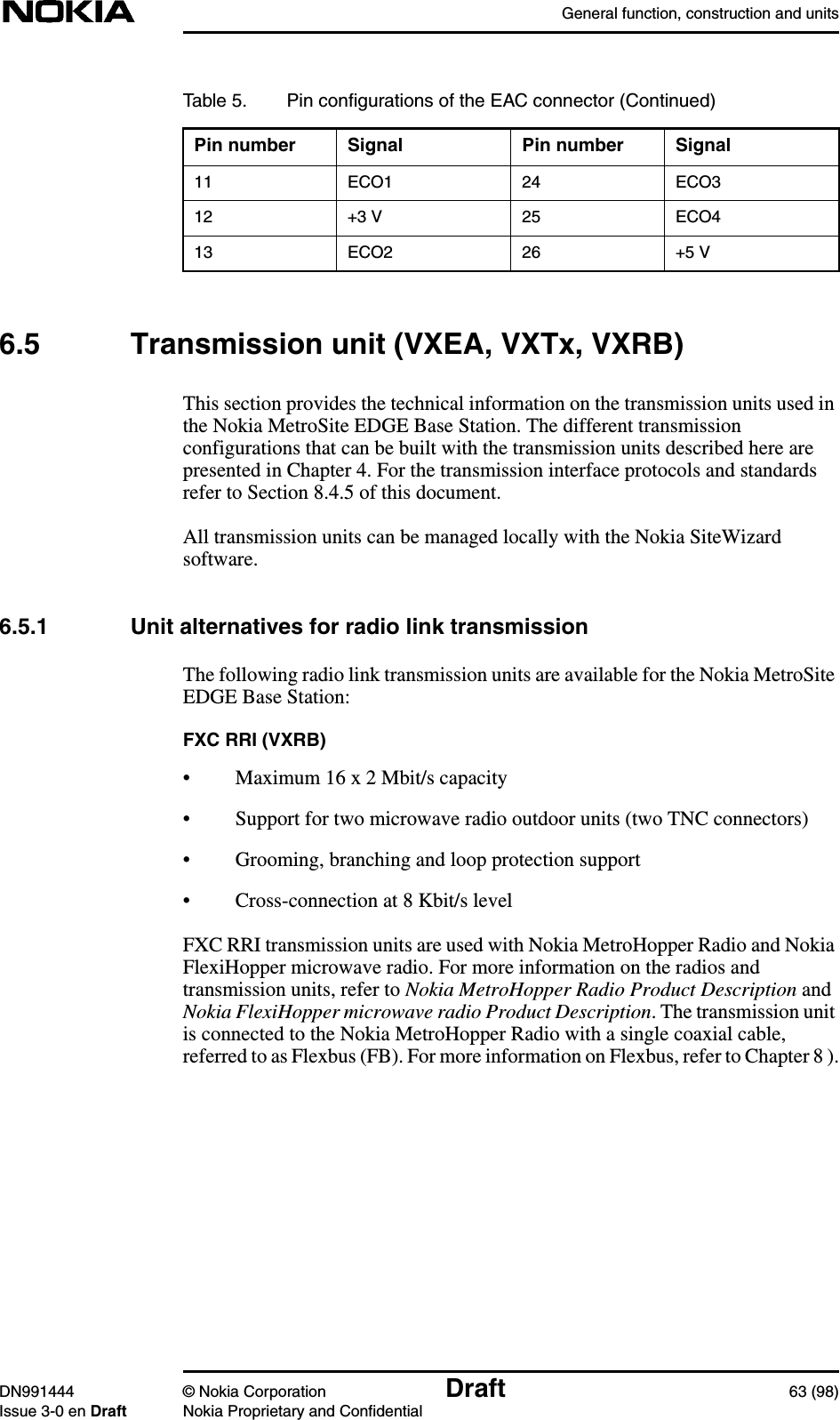
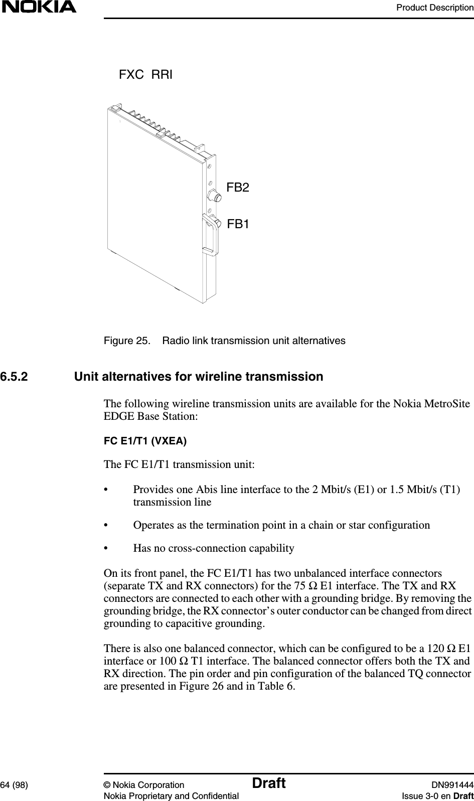
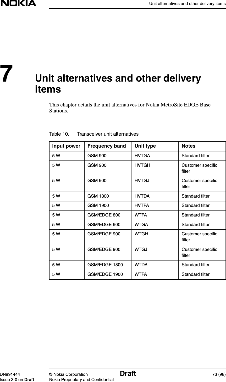
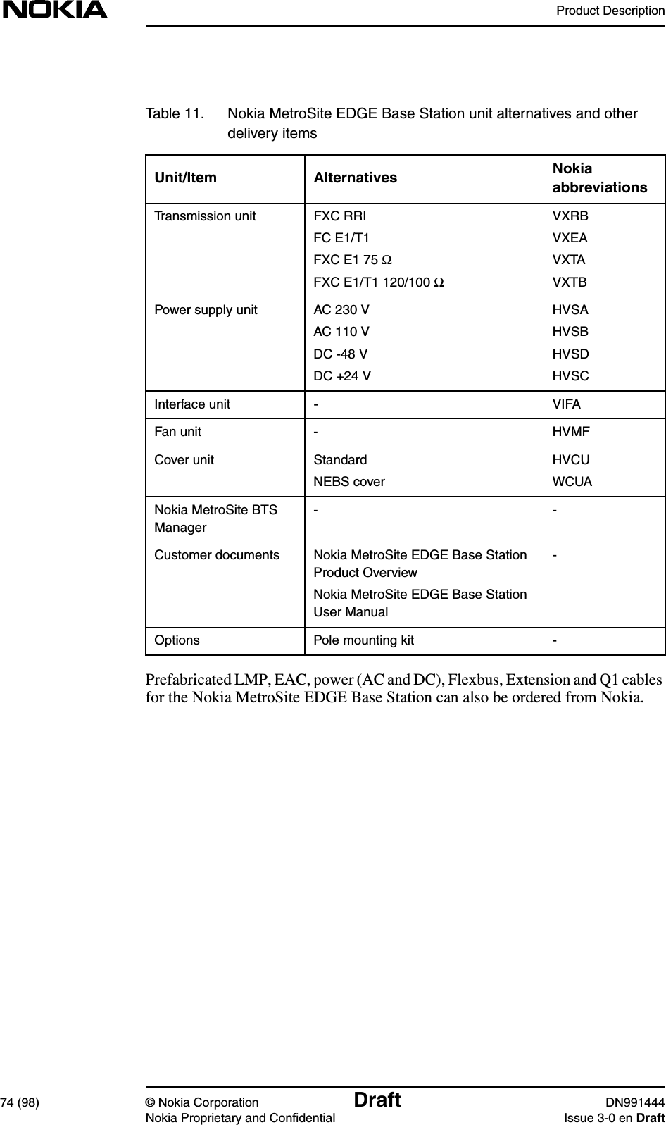
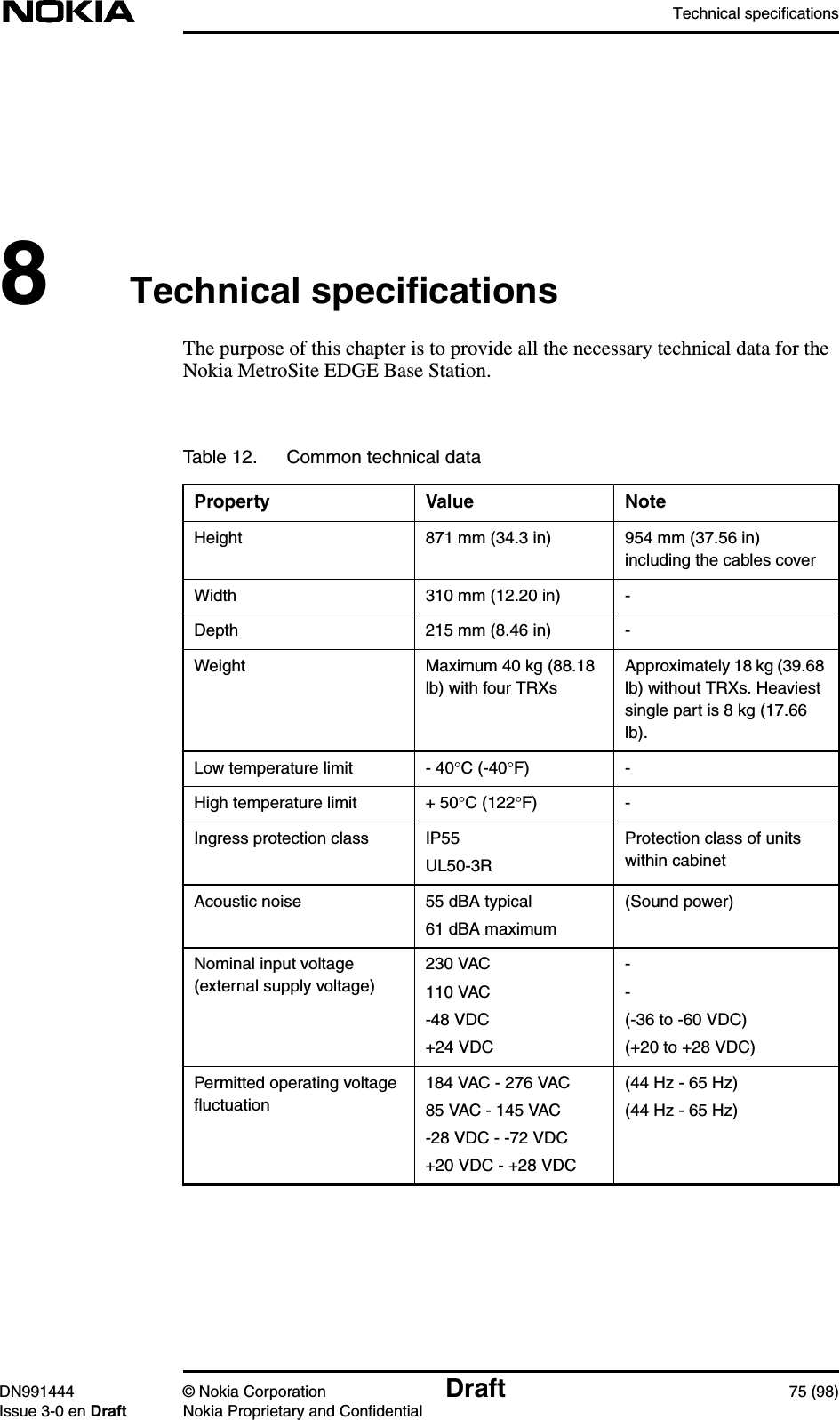
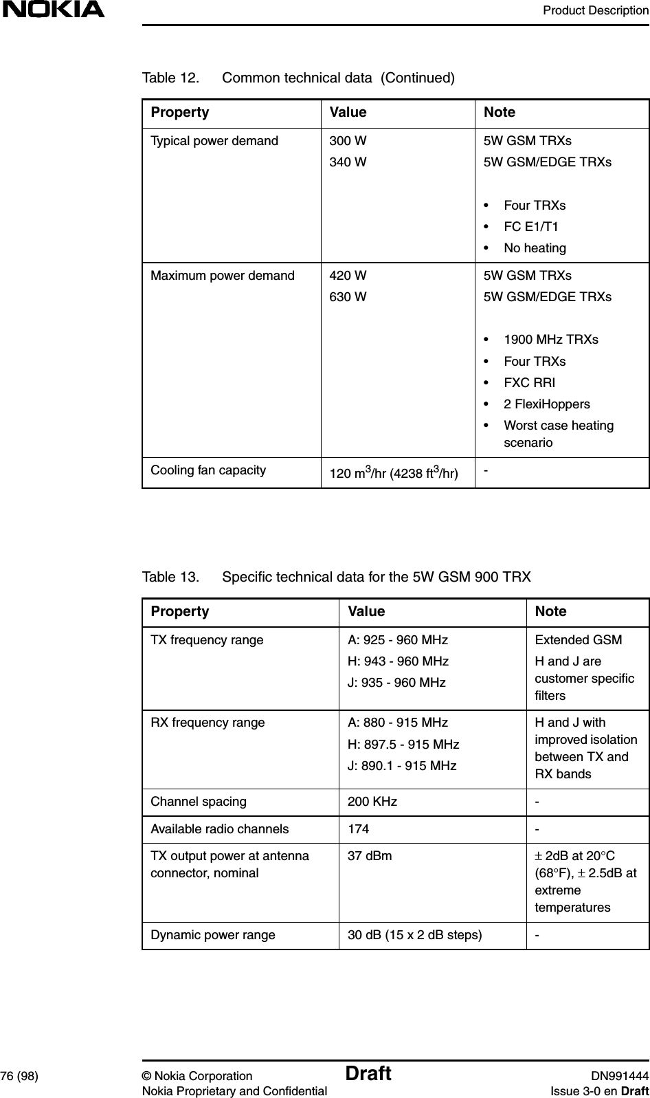
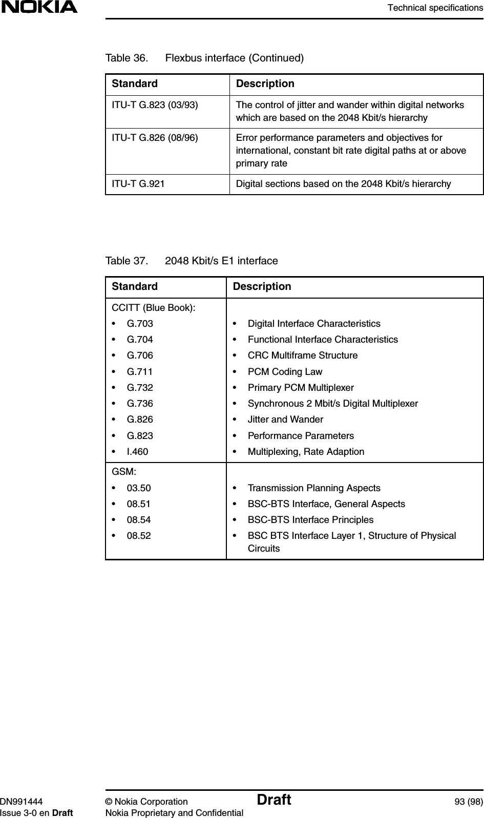
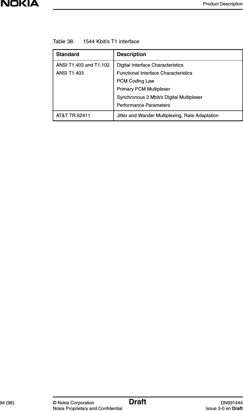
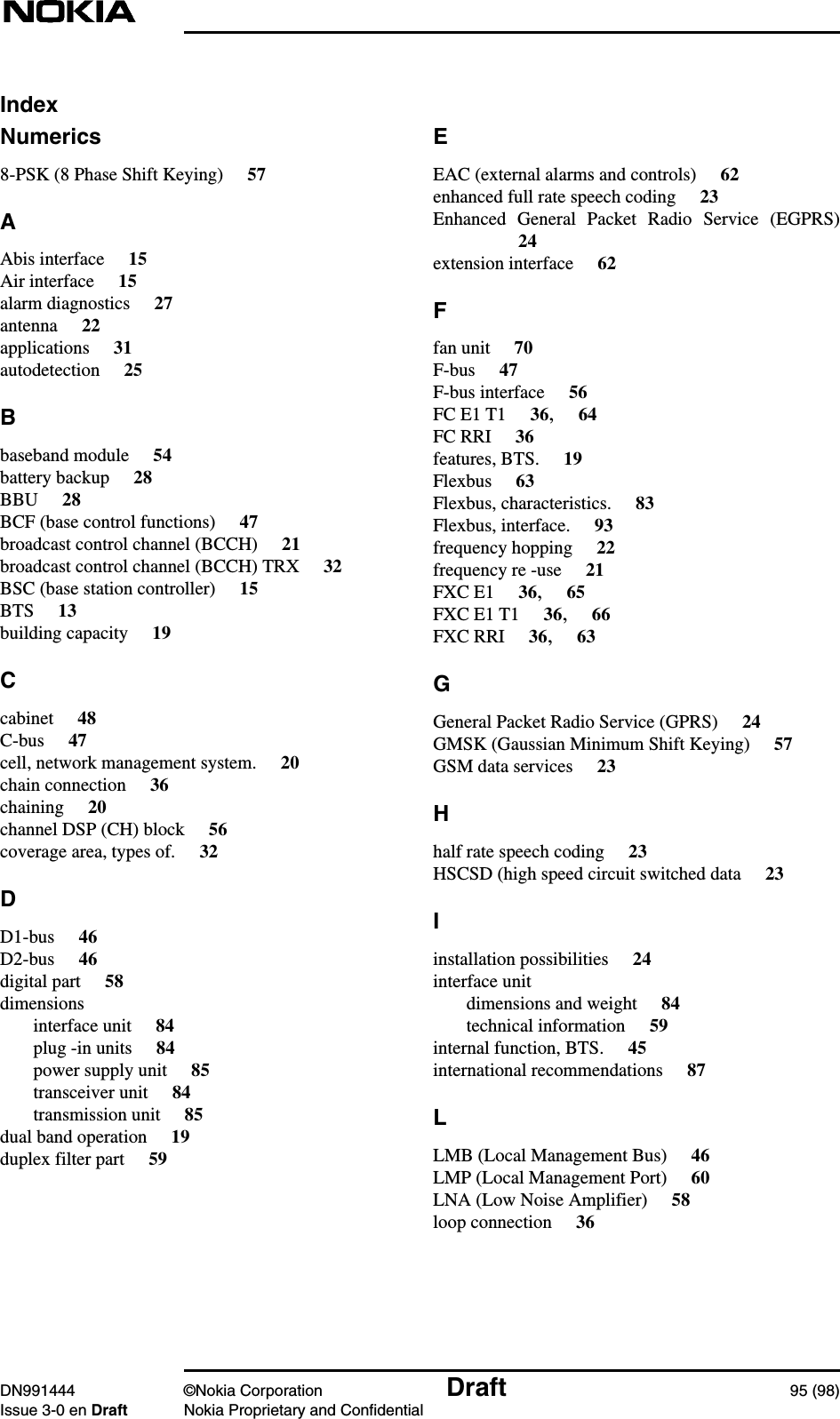
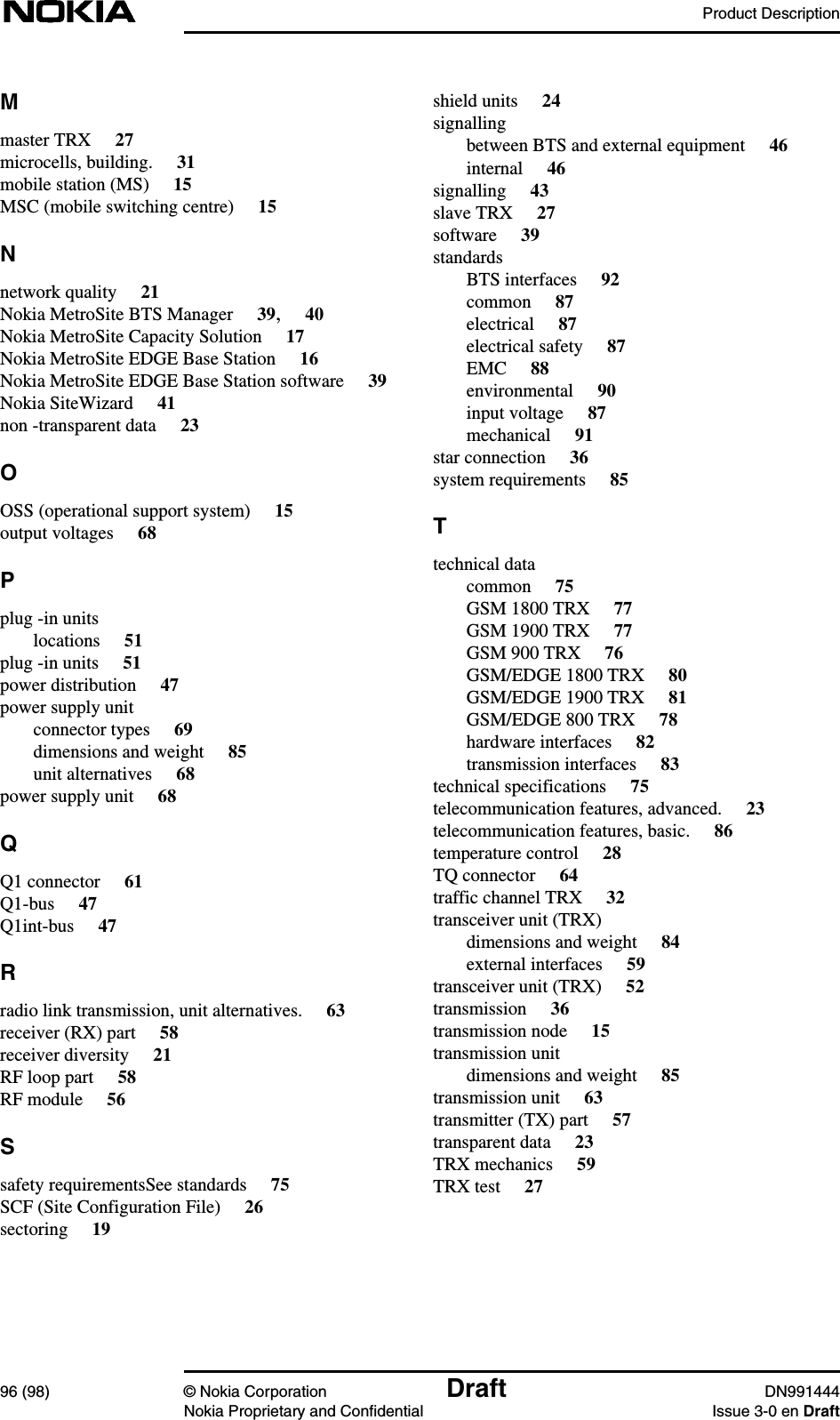
Product Desc
8.
Installation requirements
9.
Solution Accessories
10.
Warnings and cautions
11.
Installation
Product Desc
Navigation menu
Upload a User Manual
Namespaces
Wiki Guide
HTML
PDF
Info
Views
User Manual
Discussion / Help
Navigation