Nokia Solutions and Networks WTFA-01 GSM 800 Transciever User Manual dn99252966x3x0xen
Nokia Solutions and Networks GSM 800 Transciever dn99252966x3x0xen
UserManual.wiki
>
Nokia Solutions and Networks
>
WTFA-01 User Manual
>
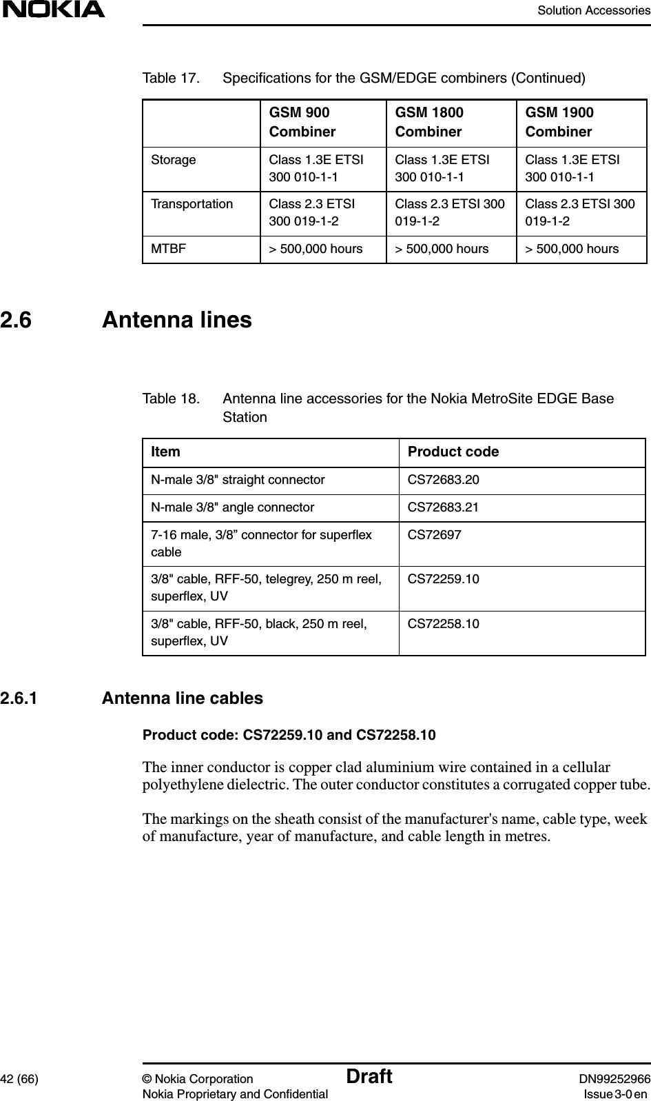
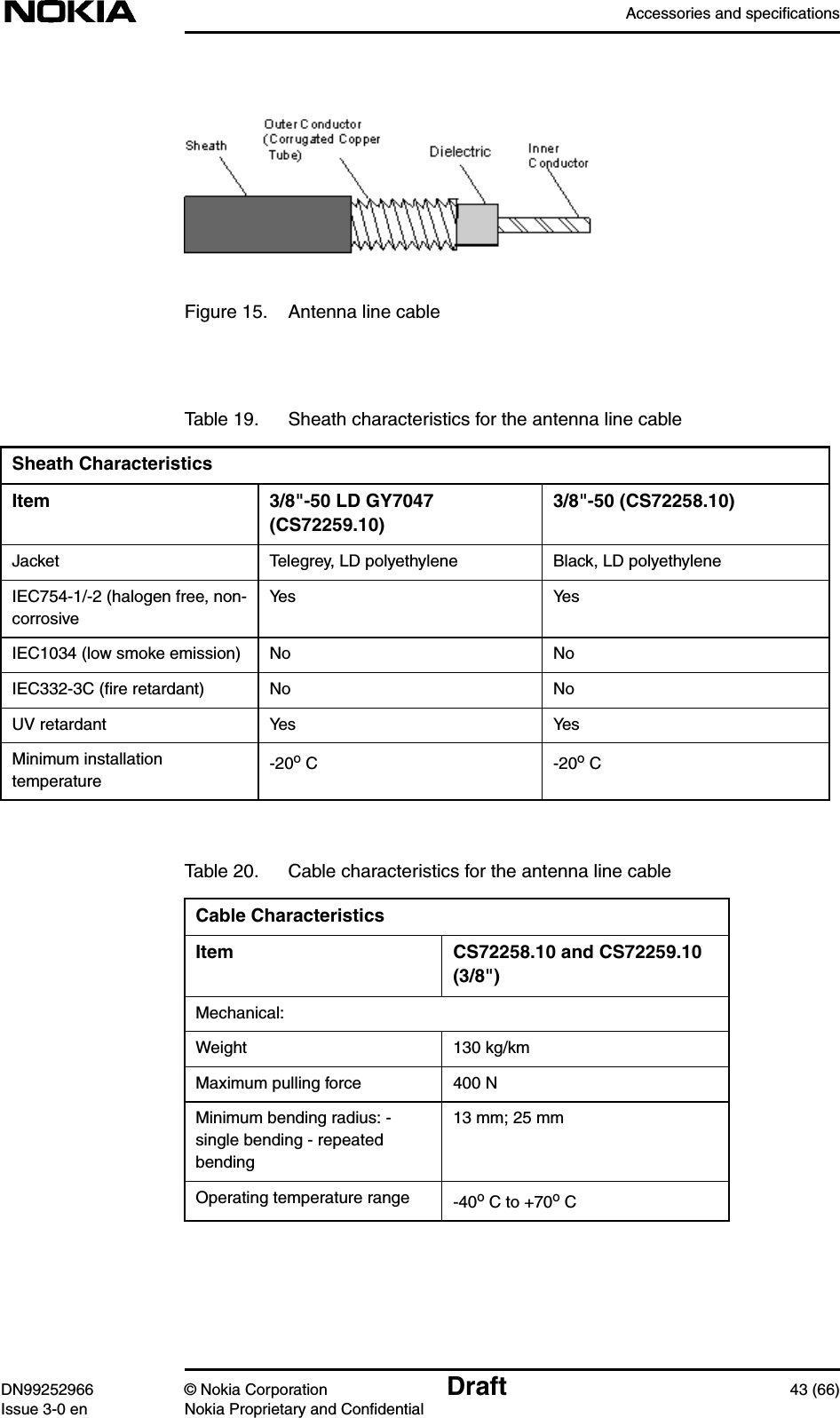
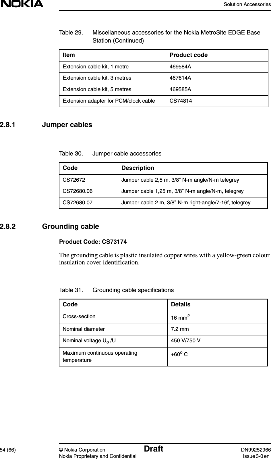
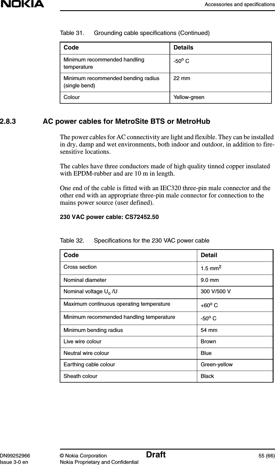
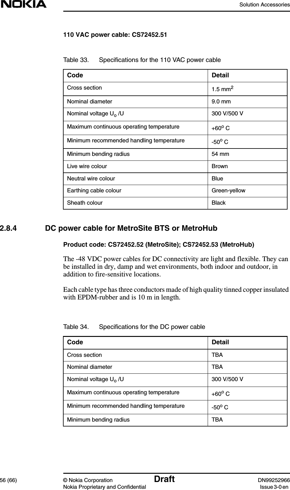
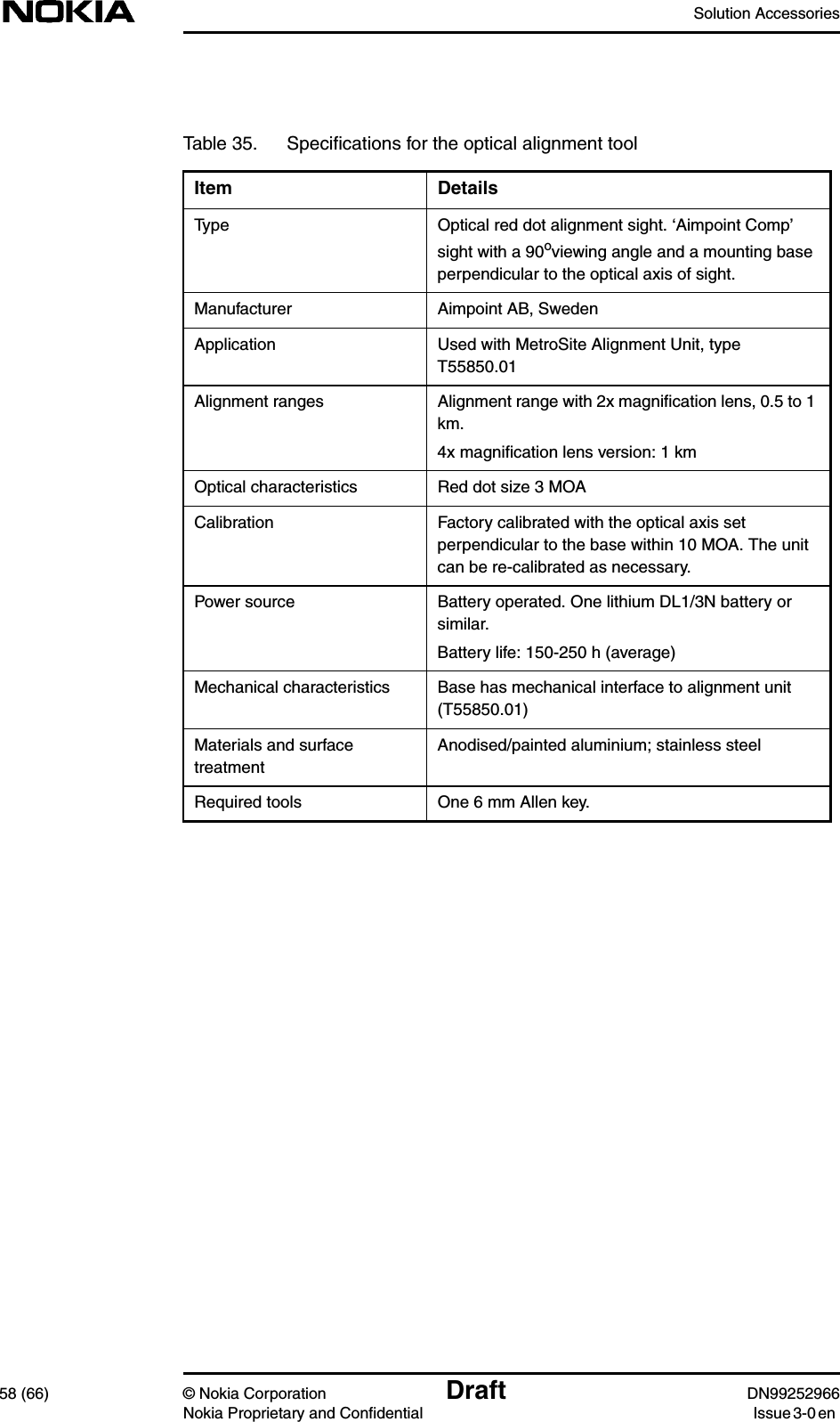
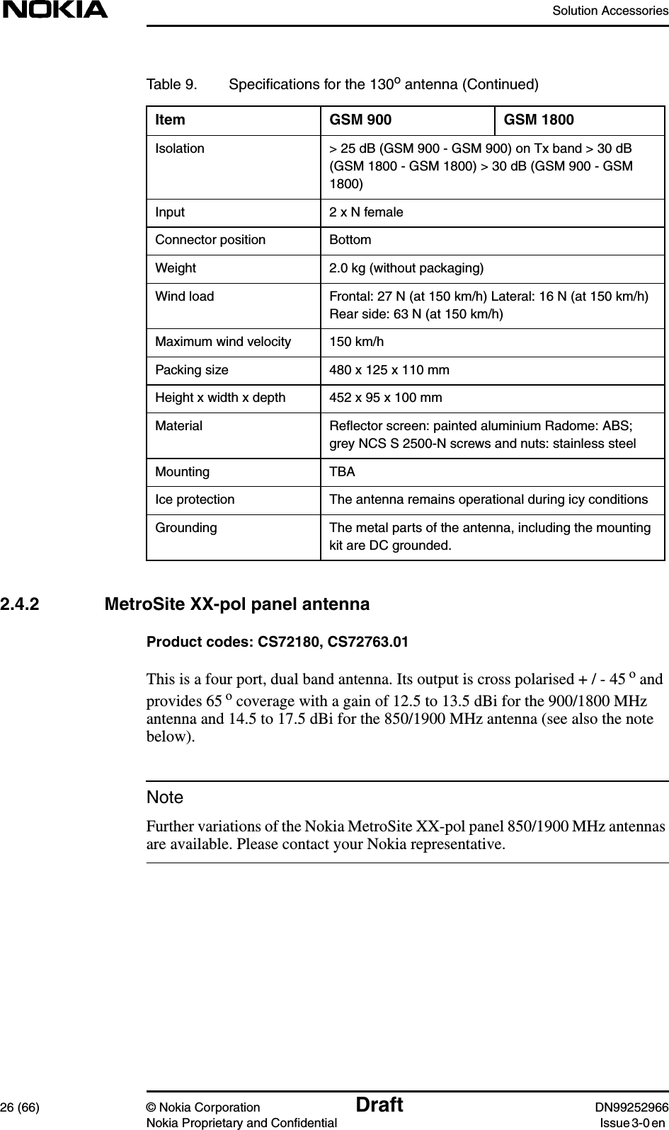
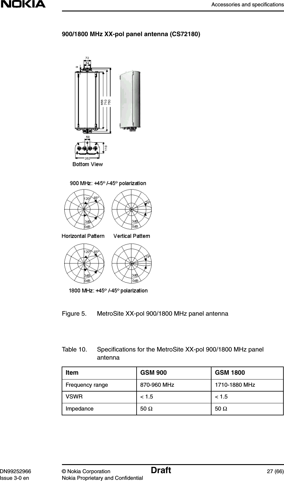
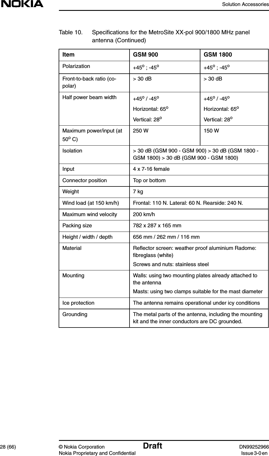
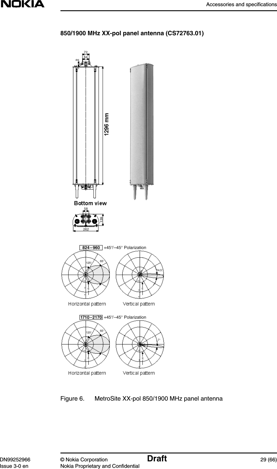
Solution Accessories
Contents
1.
Alarm Desc
2.
Commissioning
3.
Field Upgrade
4.
Glossary
5.
Guide to documentation
6.
Maintenance
7.
Product Desc
8.
Installation requirements
9.
Solution Accessories
10.
Warnings and cautions
11.
Installation
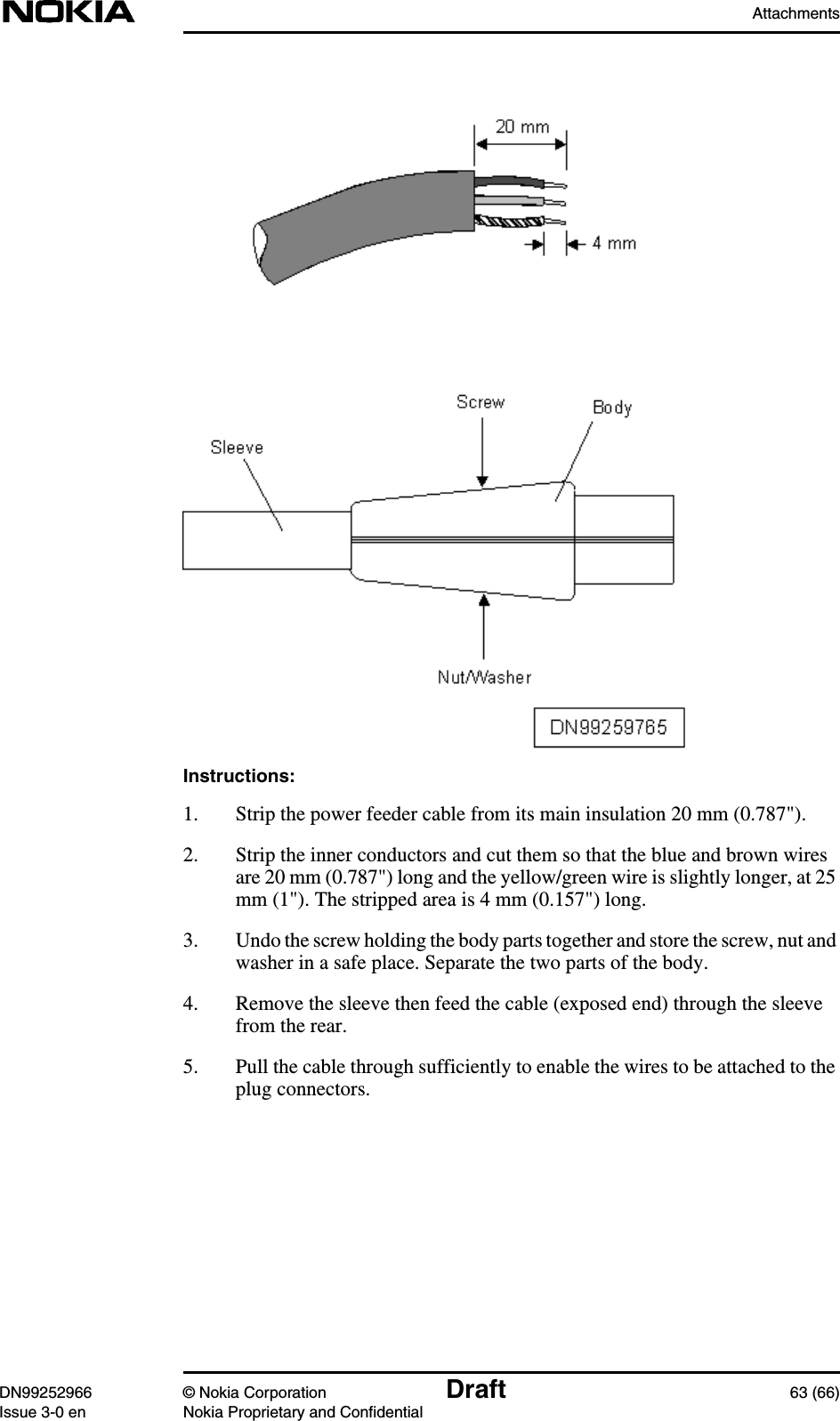
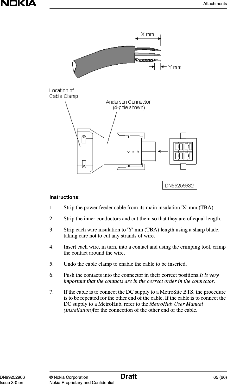
Solution Accessories
Navigation menu
Upload a User Manual
Namespaces
Wiki Guide
HTML
PDF
Info
Views
User Manual
Discussion / Help
Navigation
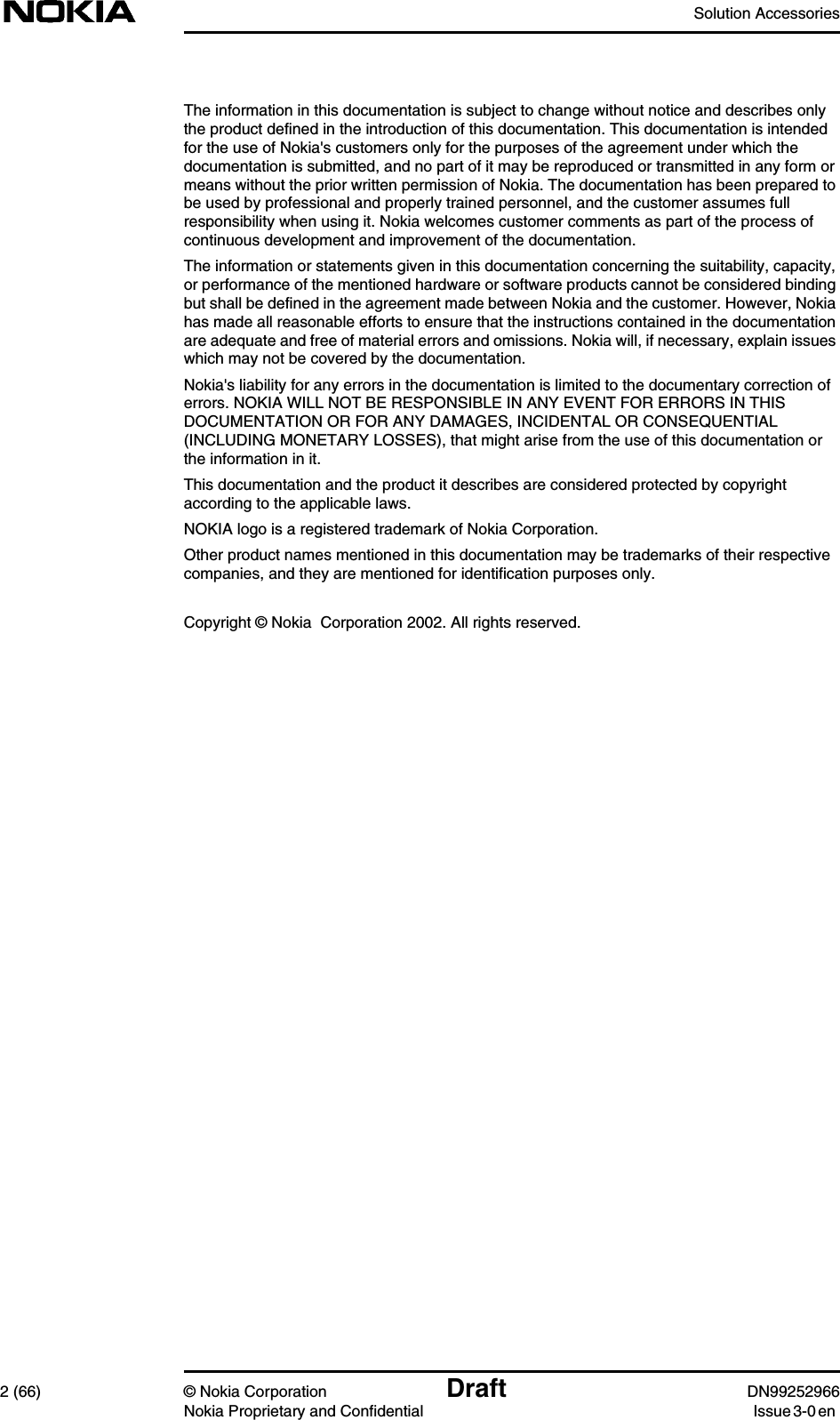


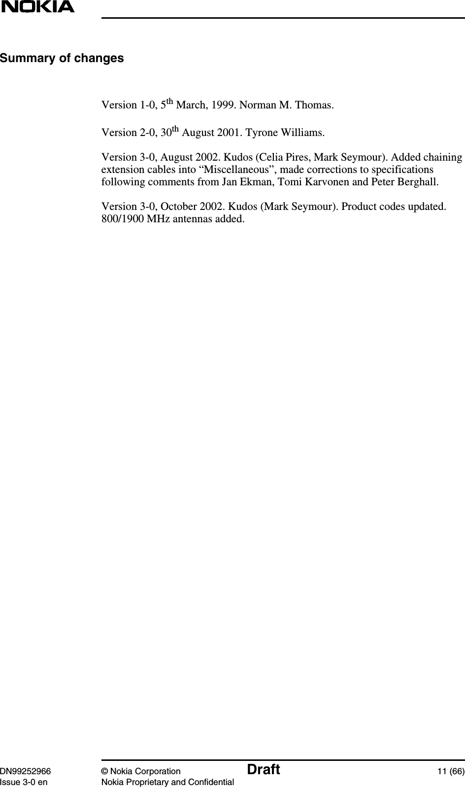


![Accessories and specificationsDN99252966 © Nokia Corporation Draft 37 (66)Issue 3-0 en Nokia Proprietary and ConfidentialInstalling the multi-band indoor panel antenna1. Fix the attachment plate to the wall using two 4 mm diameter screws. See[1] in Figure 11.2. Align the antenna over the attachment plate, keeping the cable in themiddle of the plate. See [2] in Figure 11.3. Pull the antenna downwards until it clicks into place. See [3] in Figure 11.Do not pull the antenna downwards with the antenna cable.Figure 11. Installing the indoor multi-band panel antenna2.4.6 Pole mounting clamps (50-115 mm pole diameter)Product code: CS72196This standard single unit clamp is suitable for standard Nokia antennas.The number of clamps required depends upon the antenna.](https://usermanual.wiki/Nokia-Solutions-and-Networks/WTFA-01.Solution-Accessories/User-Guide-303291-Page-37.png)