Nokia of America ONEBTS-11 UMTS-CDMA Transceiver System (850) User Manual 401703454i1
Alcatel-Lucent USA Inc. UMTS-CDMA Transceiver System (850) 401703454i1
Contents
usres manual h
Power and power alarm connections in Modular Cell 4.0B
cabinets with integrated power
4- 47
Lucent Technologies – Proprietary
See notice on first page
401-703-454
FOA Draft Issue 1
January, 2006
............................................................................................................................................................................................................................................................
Disconnect first battery
cabinet 24-VDC return
wires in the Modular Cell
4.0B primary cabinet
DANGER
Electrical Shock and Equipment Damage Hazard
When performing the following procedure, power should not
be applied to the Modular Cell 4.0B primary cabinet.
Before the installation of the second battery cabinet can begin, the
following steps must be performed to disconnect DC power from the
Modular Cell 4.0B primary cabinet to the first battery cabinet.
.....
......................................................................................................................................
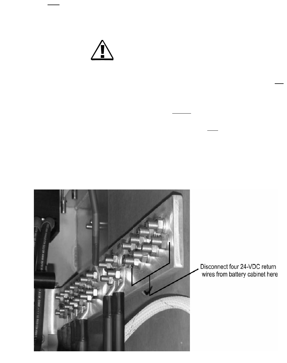
1Refer to the figure below and disconnect (and tape or insulate) the four
DC return lugs (to/from the first battery cabinet) in the Modular Cell
4.0B primary cabinet.
4-48 Lucent Technologies – Proprietary
See notice on first page 401-703-454
FOA Draft Issue 1
January, 2006
...........................................................................................................................................................................................................................................................
Power and power alarm connections in Modular Cell 4.0B
cabinets with integrated power
How to route and connect the DC cables between the first and second
.............................................................................................................................................................................................................................................................
WNG24-BC battery cabinets
Prepare the first and
second battery cabinets for
connection of the DC
cables
Perform the following steps to prepare the first and second battery
cabinets for connection of the DC cables.
Important! To determine the battery shelf type, refer to
Determine the battery shelf type on Page 4 - 19. If the battery cabinet
has type 1 battery shelves, skip the first step.
................................................................................................................................
............................................
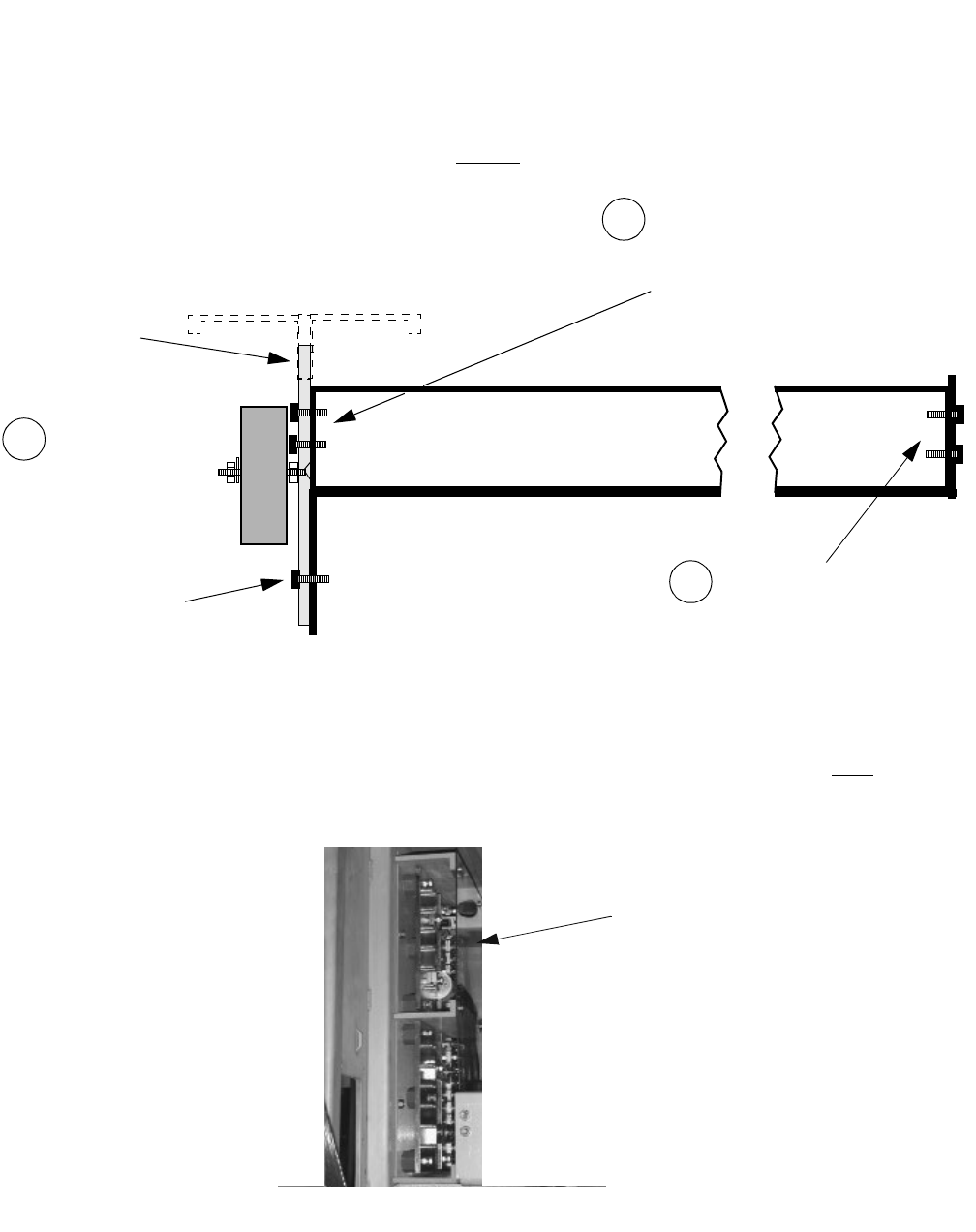
1Remove the top (shelf 5) battery retaining bracket from the second
battery cabinet (and also from the first battery cabinet if you have not
already done so). Refer to the figure below. Refer to the figure on Page
4 - 49, as well.
Important! When performing the next step, carefully note the
proper battery connections before disconnecting cables and/or
removing bus bars.
................................................................................................................................
............................................
2Disconnect and remove the following batteries from the top shelf (5) of
the first battery cabinet.
• L1, L2, and 12IR125 batteries: The left-hand string (9)
• C-11 batteries: The left-hand three batteries (1, 2, and 3)
BATTERY-
SHELF 5
FRONT VIEW
BATTERY-
SHELF 4
SHELF 5 BATTERY
RETAINING BRACKET
Power and power alarm connections in Modular Cell 4.0B
cabinets with integrated power
4- 49
Lucent Technologies – Proprietary
See notice on first page
401-703-454
FOA Draft Issue 1
January, 2006
............................................................................................................................................................................................................................................................
Important! If the battery cabinet has type 1 battery shelves,
skip the next step.
................................................................................................................................
............................................
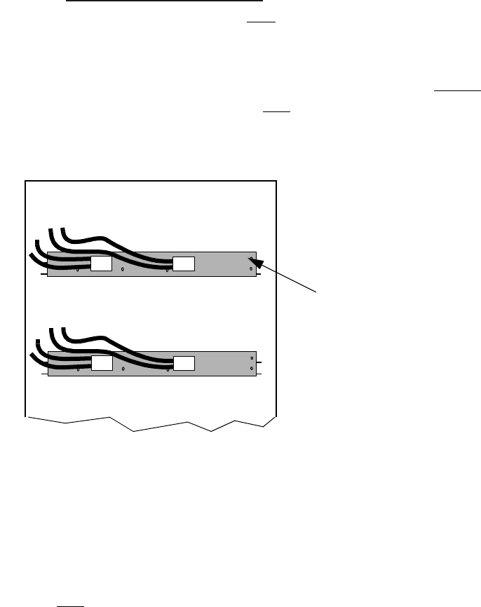
3Refer to the figure below, and remove the left-hand side rail from the top
shelf (5) in the second battery cabinet.
................................................................................................................................
............................................
4Remove the plastic cover from the DC bus bar panel in both battery
cabinets. Refer to the figure below.
TOP SHELF (5)
BATTERY
RETAINING
BRACKET
TOP BATTERY SHELF
RIGHT SIDE VIEW
REMOVE THESE
SCREWS FROM
ACROSS THE BOTTOM
OF THE BATTERY
RETAINING BRACKET
REMOVE THESE 2 SCREWS
FROM BOTH THE LEFT AND
RIGHT SIDES OF THE RETAINING
BRACKET
1
REMOVE THESE
TWO SCREWS FROM
THE REAR OF THE
LEFT SIDE RAIL
LEFT SIDE RAIL
2
3
PLASTIC COVE
R

4-50 Lucent Technologies – Proprietary
See notice on first page 401-703-454
FOA Draft Issue 1
January, 2006
...........................................................................................................................................................................................................................................................
Power and power alarm connections in Modular Cell 4.0B
cabinets with integrated power
Connect the DC cables in
the second battery cabinet Perform the following steps to connect the DC cables in the second
battery cabinet.
................................................................................................................................
............................................
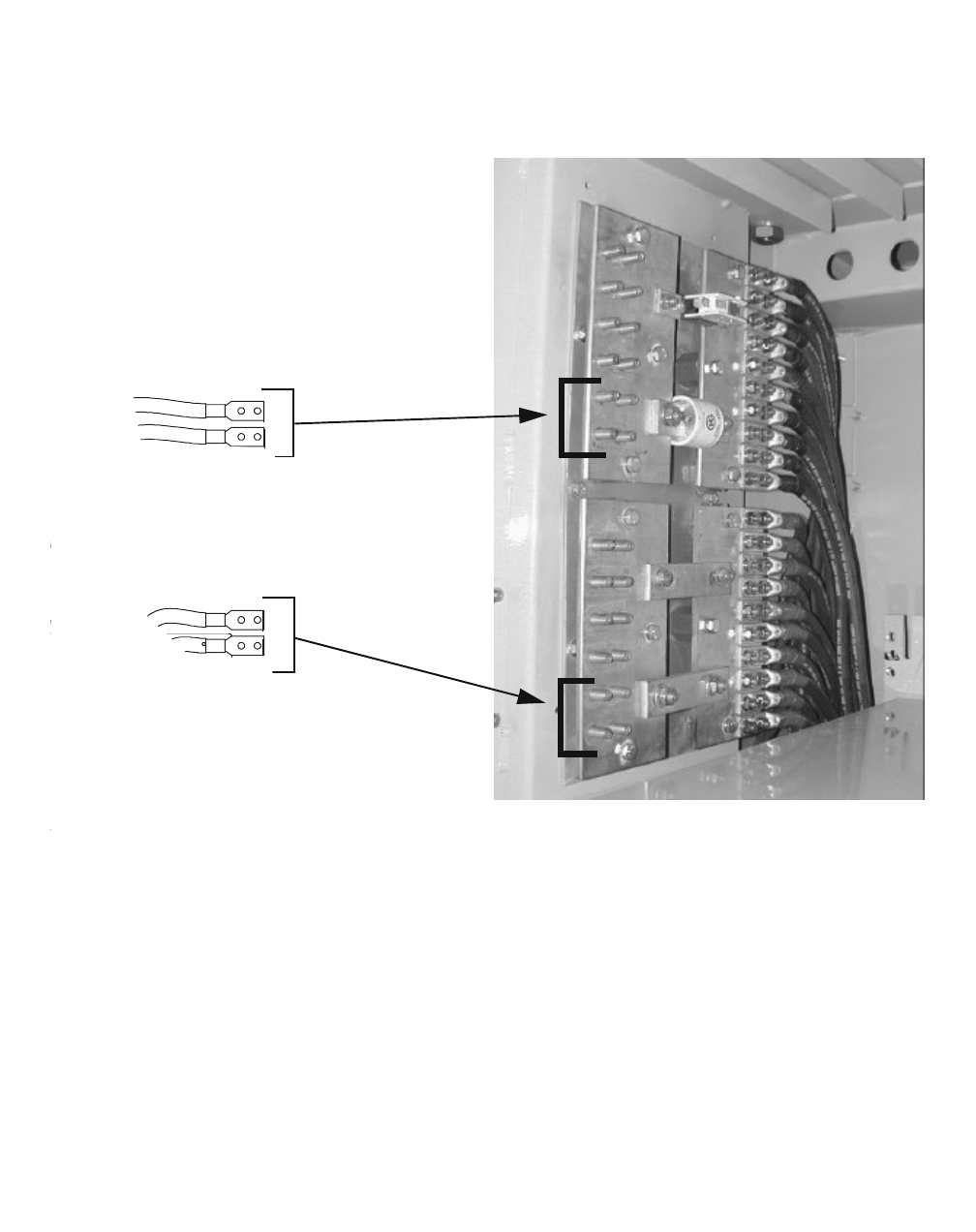
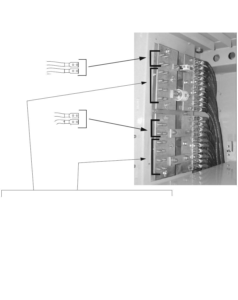
1Connect the two +24-VDC cables (marked red) to the +24-VDC
(lower) bus bar in the bottom two positions, leaving the top four
positions blank. Refer to the figure on Page 4 - 51.
................................................................................................................................
............................................
2Connect the two 24-VDC return cables (black) to the 24-VDC return
(upper) bus bar in the bottom two positions, leaving the top four
positions blank. Refer to the figure on Page 4 - 51.
................................................................................................................................
............................................
3Torque all four DC cable connections. Refer to the electrical torque
specifications provided in Chapter 1.
................................................................................................................................
............................................
4Route the cables into the first battery cabinet through the square opening
between the cabinets.
................................................................................................................................
............................................
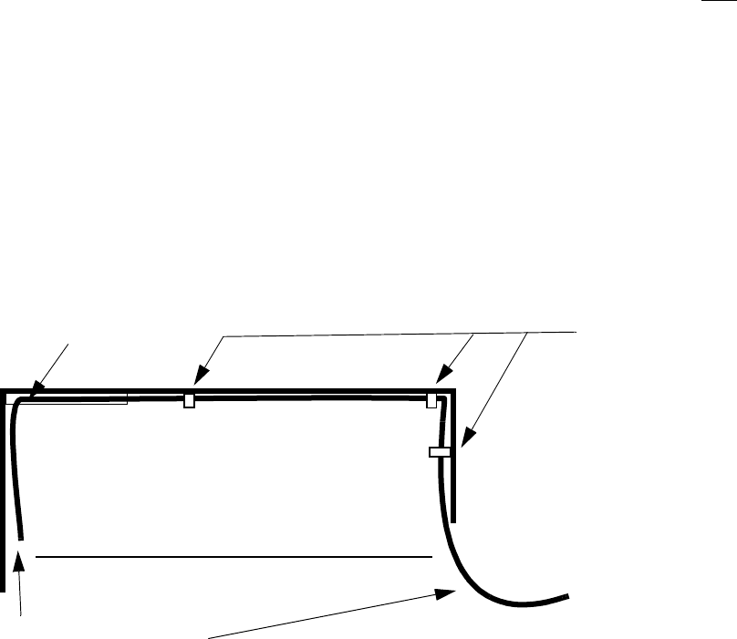
5Using wire ties, dress the DC cables to the interior left side of the second
battery cabinet.
................................................................................................................................
............................................
6Do not replace the plastic cover on the DC bus bar panel or the left-hand
side rail, if applicable (in the second battery cabinet), at this time. The
fuse alarm connection remains to be completed.
Important! If the battery cabinet has type 1 battery shelves,
skip the next step.
Power and power alarm connections in Modular Cell 4.0B
cabinets with integrated power
4- 51
Lucent Technologies – Proprietary
See notice on first page
401-703-454
FOA Draft Issue 1
January, 2006
............................................................................................................................................................................................................................................................
................................................................................................................................
............................................
7Do not replace the top shelf battery retaining bracket in the second
battery cabinet (batteries must be installed prior to reinstallation of the
retaining bracket).
+24-VDC CABLES
(MARKED RED)
24-VDC RETURN
CABLES
DC BUS PANELS
4-52 Lucent Technologies – Proprietary
See notice on first page 401-703-454
FOA Draft Issue 1
January, 2006
...........................................................................................................................................................................................................................................................
Power and power alarm connections in Modular Cell 4.0B
cabinets with integrated power
Connect the battery cabinet
cables in the first battery
cabinet
Perform the following steps to connect the DC cables in the first
WNG24-BC battery cabinet.
................................................................................................................................
............................................
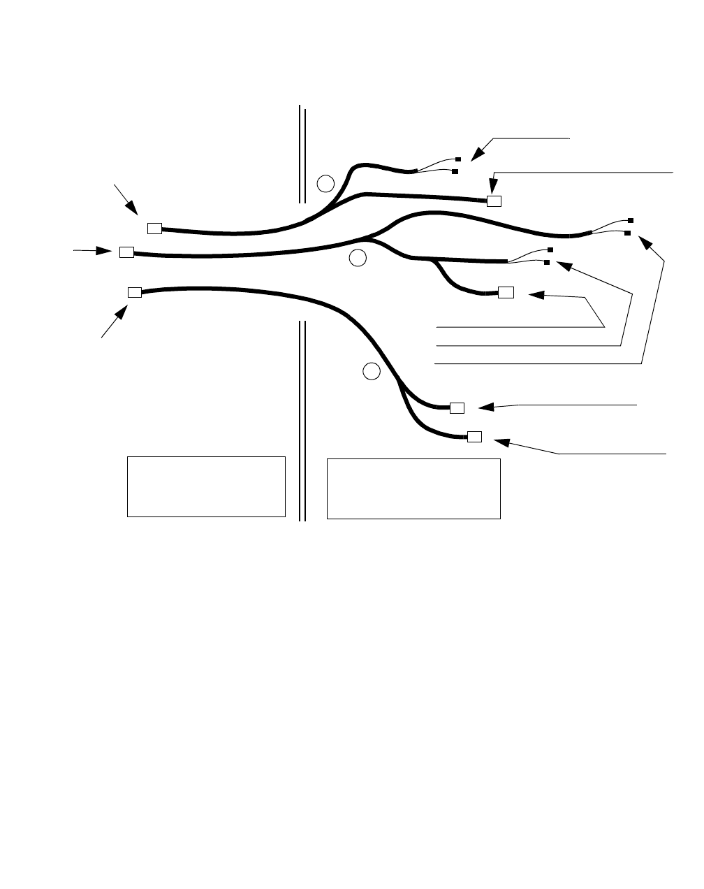
1Route and dress the DC cables from the second battery cabinet to the DC
bus bars in the first battery cabinet. Do this in such a way that they do
not interfere with replacement of batteries or door closure. Refer to the
figure below.
................................................................................................................................
............................................
2Connect the two +24-VDC cables (marked red) to the +24-VDC
(lower) bus bar in the top two positions. Refer to the figure on Page 4 -
53.
................................................................................................................................
............................................
3Connect the two 24-VDC return cables (black) to the 24-VDC return
(upper) bus bar in the top two positions. Refer to the figure on Page 4 -
53.
................................................................................................................................
............................................
4Torque all four DC cable connections. Refer to the electrical torque
specifications provided in Chapter 1.
"U" CHANNEL TIE POINTS FOR DC
CABLES
FIRST WNG24-BC BATTERY CABINET
FOUR DC CABLES
FROM THE SECOND
BATTERY CABINET
Power and power alarm connections in Modular Cell 4.0B
cabinets with integrated power
4- 53
Lucent Technologies – Proprietary
See notice on first page
401-703-454
FOA Draft Issue 1
January, 2006
............................................................................................................................................................................................................................................................
................................................................................................................................
............................................
5Replace the plastic cover on the DC bus bar panel (in the first battery
cabinet). Refer to the figure below.
................................................................................................................................
............................................
6Replace the batteries that were previously removed.
Important! When performing the next step, do not plug in the
battery connectors on the retaining bracket.
................................................................................................................................
............................................
7Replace the top shelf battery retaining bracket.
+24-VDC CABLES
(MARKED RED)
DC BUS PANELS
24-VDC
RETURN
CABLES
FOUR EACH 24-VDC RETURN AND +24-VDC CABLES TO/FROM THE
POWER CABINET WERE CONNECTED HERE WHEN THE FIRST BATTERY
CABINET WAS INSTALLED

4-54 Lucent Technologies – Proprietary
See notice on first page 401-703-454
FOA Draft Issue 1
January, 2006
...........................................................................................................................................................................................................................................................
Power and power alarm connections in Modular Cell 4.0B
cabinets with integrated power
How to route and connect the alarm and fan power/alarm cables in the
.............................................................................................................................................................................................................................................................
second WNG24-BC battery cabinet
Overview The AC cable was shipped already terminated in the second WNG24-
BC battery cabinet. The remaining cables, all of which will pass
between the two battery cabinets, are not yet terminated in the second
battery cabinet.
Identify and place the alarm
and fan power/alarm cables
between the two battery
cabinets
Perform the following steps to place the alarm and fan power/alarm
cables between the two battery cabinets and identify the second battery
cabinet ends.
.....
......................................................................................................................................
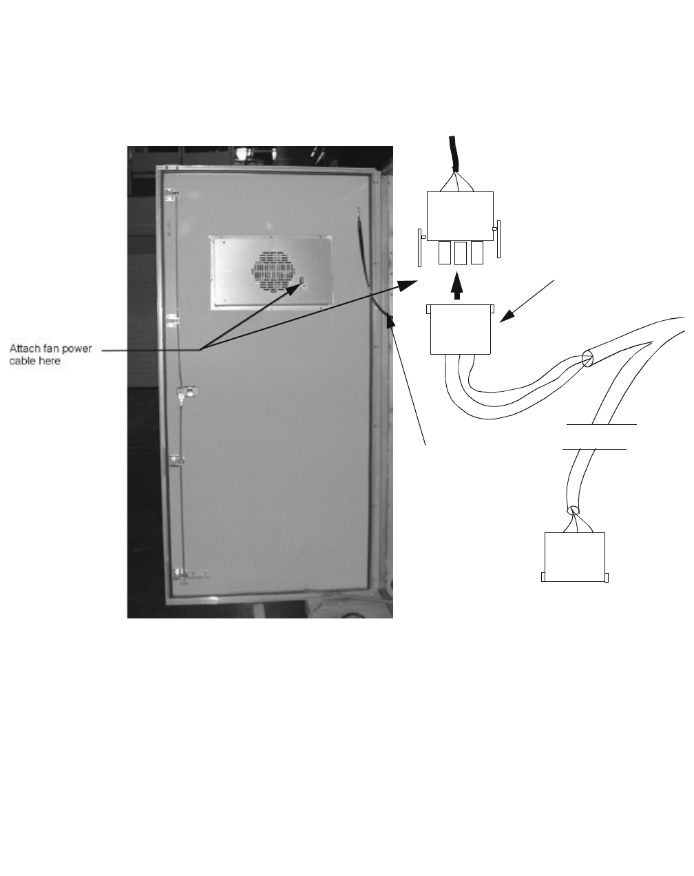
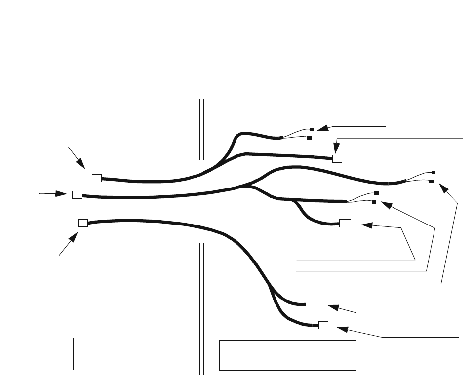
1Identify the following cables shipped with the second WNG24-BC
battery cabinet. Refer to the figure on Page 4 - 55 cable and connector
identification.
1. The fuse alarm cable
a. Connectors SW1 and SW4
b. Connector P309 (not used)
2. The intrusion alarm cable
a. Connector P307 (not used)
b. Connectors "C" and "NC" FRONT
c. Connectors "C" and "NC" REAR
3. The fan power/alarm cable
a. Connector "FAN" (the fan power/alarm connector)
b. P9 (not used)
Important! A thermal probe cable and thermal probe are not
shipped with the second battery cabinet. A thermal probe cable
and probe, shipped with the first battery cabinet, was installed in
the first battery cabinet. This cable and probe will be moved to the
second battery cabinet after installation of the batteries. Refer to
Chapter 5
Power and power alarm connections in Modular Cell 4.0B
cabinets with integrated power
4- 55
Lucent Technologies – Proprietary
See notice on first page
401-703-454
FOA Draft Issue 1
January, 2006
............................................................................................................................................................................................................................................................
................................................................................................................................
............................................
2Place the cables through the square opening between the cabinets as
shown in the figure below.
BATTERY CABINET
FAN POWER CABLE
(J9)
INTRUSION
ALARM CABLE
(J307)
FUSE ALARM
CABLE (J309)
FIRST WNG24-BC
BATTERY
CABINET
a. SW1 / SW4
b. P309 (NOT USED)
a. P307 (NOT USED)
b. "C" AND "NC" (FRONT)
c. "C" AND "NC" (REAR)
a. “FAN”
b. P9 (NOT
USED)
SECOND WNG24-BC
BATTERY
CABINET
1
2
3
4-56 Lucent Technologies – Proprietary
See notice on first page 401-703-454
FOA Draft Issue 1
January, 2006
...........................................................................................................................................................................................................................................................
Power and power alarm connections in Modular Cell 4.0B
cabinets with integrated power
Route and connect the fan
power/alarm cable in the
second WNG24-BC battery
cabinet
Perform the following steps to route and connect the fan power/alarm
cable in the second WNG24-BC battery cabinet.
................................................................................................................................
............................................
1Attach the fan power/alarm cable (labeled "FAN") in the second
WNG24-BC battery cabinet. Refer to the figure on Page 4 - 57.
................................................................................................................................
............................................
2Using wire ties, dress the fan power/alarm cable and the P9 cable
connector to the left interior wall of the battery cabinet.
Power and power alarm connections in Modular Cell 4.0B
cabinets with integrated power
4- 57
Lucent Technologies – Proprietary
See notice on first page
401-703-454
FOA Draft Issue 1
January, 2006
............................................................................................................................................................................................................................................................
................................................................................................................................
............................................
3Route and attach the cables in such a way that they do not interfere with
door closure or installation/replacement of parts. Refer to the figure
below.
P9
(NOT USED)
"FAN" FOR
SECOND
WNG24-BC
BATTERY
CABINET
FAN
GROUND
STRAP
P9
FAN
4-58 Lucent Technologies – Proprietary
See notice on first page 401-703-454
FOA Draft Issue 1
January, 2006
...........................................................................................................................................................................................................................................................
Power and power alarm connections in Modular Cell 4.0B
cabinets with integrated power
Route and connect the fuse
alarm cable in the second
WNG24-BC battery cabinet
Perform the following steps to route and connect the fuse alarm cables
in the second WNG24-BC battery cabinet.
................................................................................................................................
............................................
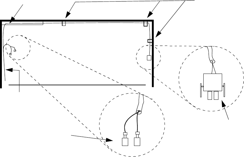
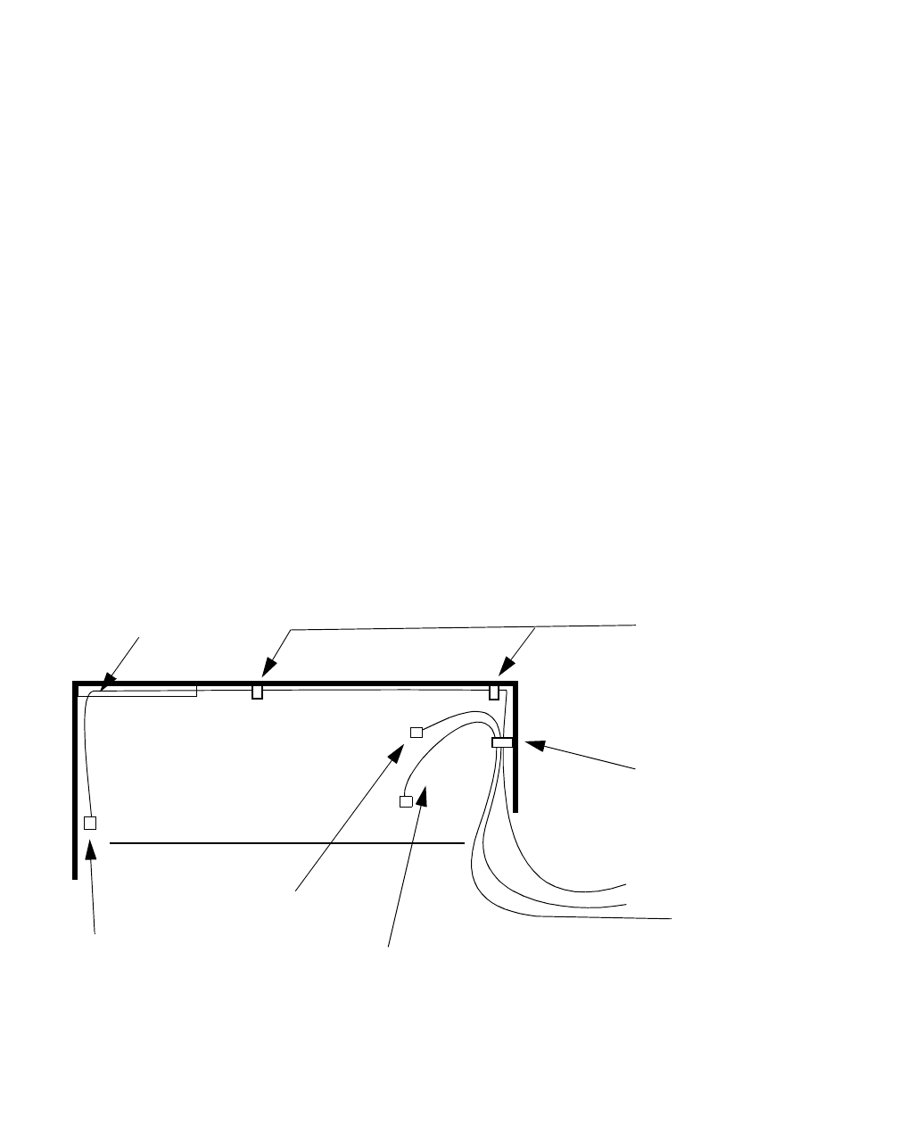
1Dress the fuse alarm cable that have spade lugs to the interior left wall
of the battery cabinet and secure it with wire ties. Refer to the figure
below.
................................................................................................................................
............................................
2Route the P309 cable and connector across the interior top of the cabinet
to the square opening. (on the right side of the cabinet). Refer to the
figure below.
................................................................................................................................
............................................
3Secure the P309 fuse alarm cable to the interior top of the battery cabinet
with wire ties at the "U" channel, and at the tie point locations. Refer to
the figure below.
FUSE ALARM
CABLES
"U" CHANNEL TIE POINTS FOR
FUSE ALARM
CABLES
P309
(NOT
USED)
SPADE LUG CONNECTIONS FOR
FUSE ALARM IN SECOND
WNG24-BC BATTERY CABINET
Power and power alarm connections in Modular Cell 4.0B
cabinets with integrated power
4- 59
Lucent Technologies – Proprietary
See notice on first page
401-703-454
FOA Draft Issue 1
January, 2006
............................................................................................................................................................................................................................................................
................................................................................................................................
............................................
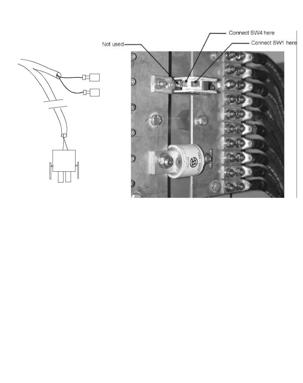
4Connect the fuse alarm cable. Refer to the figure below.
................................................................................................................................
............................................
5Replace the plastic cover on the DC bus bar panel in the second battery
cabinet, putting the four screws in the top four locations, only.
Important! If the battery cabinet has type 1 battery shelves,
skip the next step.
................................................................................................................................
............................................
6Replace the left-hand side rail on the top battery shelf in the second
battery cabinet.
Important! If the battery cabinet has type 1 battery shelves, do
not reinstall the top shelf battery retaining bracket at this time,
unless the top shelf will not be populated with batteries.
SW1
P
309
(
NOT USED)
SW4
P309
4-60 Lucent Technologies – Proprietary
See notice on first page 401-703-454
FOA Draft Issue 1
January, 2006
...........................................................................................................................................................................................................................................................
Power and power alarm connections in Modular Cell 4.0B
cabinets with integrated power
Route and connect the
intrusion alarm cables in
the second WNG24-BC
battery cabinet
Perform the following steps to route and connect the intrusion alarm
cables in the second WNG24-BC battery cabinet.
................................................................................................................................
............................................
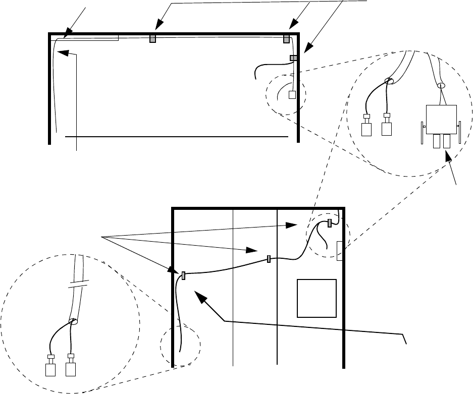
1Route the intrusion alarm cables across the interior top of the cabinet to
the square opening (on the right side of the cabinet). Refer to the figure
below.
................................................................................................................................
............................................
2Secure the cables to the interior top of the battery cabinet with wire ties
at the "U" channel, and at the tie point locations shown. Refer to the
figure below.
INTRUSION ALARM
CABLES
"U" CHANNEL TIE POINTS FOR
INTRUSION ALARM
CABLES
FRONT
P307
(NOT
USED)
FRONT VIEW
INSIDE RIGHT VIEW
TO REAR
INTRUSION
ALARM
TIE POINTS FOR
REAR INTRUSION
ALARM CABLE
REAR
Power and power alarm connections in Modular Cell 4.0B
cabinets with integrated power
4- 61
Lucent Technologies – Proprietary
See notice on first page
401-703-454
FOA Draft Issue 1
January, 2006
............................................................................................................................................................................................................................................................
................................................................................................................................
............................................
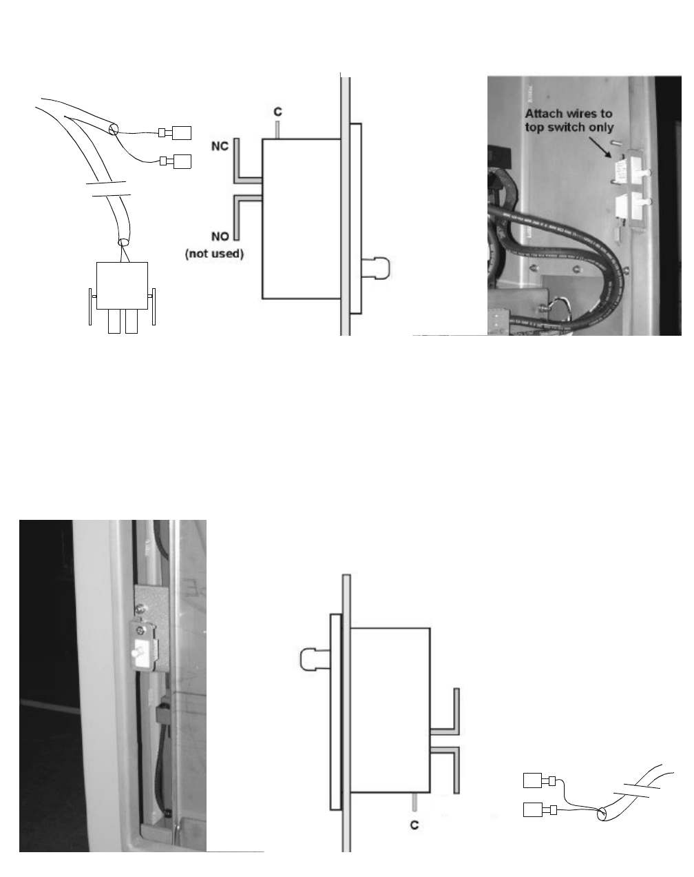
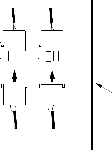
3Connect the front intrusion cable as shown. Refer to the figure below.
................................................................................................................................
............................................
4Route and secure the rear intrusion cable to the interior right side of the
battery cabinet with wire ties at the tie point locations. Refer to the
figure on Page 4 - 60.
................................................................................................................................
............................................
5Connect the rear intrusion cable as shown. Refer to the figure below.
C
P
307
(
NOT USED) DOOR NC
SHORTER CABLE (FRONT)
P307
C
DOOR NC
LONGER CABLE
(REAR)
NC
NO
(NOT USED)
4-62 Lucent Technologies – Proprietary
See notice on first page 401-703-454
FOA Draft Issue 1
January, 2006
...........................................................................................................................................................................................................................................................
Power and power alarm connections in Modular Cell 4.0B
cabinets with integrated power
How to route and connect the alarm and fan power/alarm cables in the
.............................................................................................................................................................................................................................................................
first WNG24-BC battery cabinet
Overview This section provides instructions on how to route and connect the
alarm and fan power/alarm cables in the first WNG24-BC battery
cabinet.
Route alarm and fan power/
alarm cables in the first
WNG24-BC battery cabinet
Perform the following steps to route the alarm and fan power/alarm
cables in the first WNG24-BC battery cabinet.
1.
The fuse alarm cable (J309 on the first battery cabinet end)
2.
T
he intrusion alarm cable (J307 on the first battery cabinet end)
Refer to the figure below.
3.
T
he battery cabinet fan power/alarm cable (J9 on the first battery
cabinet end)
3. BATTERY CABINET
FAN POWER CABLE
(J9)
2
. INTRUSION
A
LARM CABLE
(
J307)
1. FUSE ALARM
CABLE (J309)
FIRST WNG24-BC
BATTERY CABINET
FUSE ALARM CABLE
SW1 / SW4
P309 (NOT USED)
INTRUSION ALARM
P307 (NOT USED)
C / DOOR NC (FRONT)
C / DOOR NC (REAR)
FAN POWE
R
“FAN”
P9 (NOT
USED)
SECOND WNG24-BC
BATTERY CABINET
Power and power alarm connections in Modular Cell 4.0B
cabinets with integrated power
4- 63
Lucent Technologies – Proprietary
See notice on first page
401-703-454
FOA Draft Issue 1
January, 2006
............................................................................................................................................................................................................................................................
................................................................................................................................
............................................
6Route the identified cables from the second WNG24-BC battery
cabinet, into the first, and to the locations shown in the figure below.
• Route the fuse alarm cable (J309) and intrusion alarm cable (J307)
to right side of the first battery cabinet, just above the feed-
through opening from the second cabinet.
• Route the fan power/alarm cable (J9) across the top of the first
battery cabinet, through the "U" channel, to the left side of the
cabinet.
Important! When performing the next step, the tied-down
cables must not interfere with:
• Replacement of batteries
• Opening or closure of the first WNG24-BC battery cabinet
front door
................................................................................................................................
............................................
7Using wire ties, secure the cables to the "flash" tie point locations. Refer
to the figure below.
"U" CHANNEL TIE POINTS FOR FAN
POWER CABLE
FIRST WNG24-BC BATTERY CABINET
TIE POINT FOR FAN
POWER CABLE AND
TWO ALARM
CABLES
FUSE ALARM
CABLE (J309)
INTRUSION
ALARM CABLE
(J307)
BATTERY CABINET
FAN POWER CABLE
(J9)
4-64 Lucent Technologies – Proprietary
See notice on first page 401-703-454
FOA Draft Issue 1
January, 2006
...........................................................................................................................................................................................................................................................
Power and power alarm connections in Modular Cell 4.0B
cabinets with integrated power
Connect alarm cables in
the first WNG24-BC battery
cabinet
Perform the following steps to connect the alarm cables in the first
WNG24-BC battery cabinet.
................................................................................................................................
............................................
1Connect the J307 connector to connector P307 in the first WNG24-BC
battery cabinet. Refer to the figure below.
................................................................................................................................
............................................
2Connect the J309 connector to connector P309 in the first WNG24-BC
battery cabinet. Refer to the figure below.
................................................................................................................................
............................................
3Using wire ties, dress the alarm cables to the interior right side of the
first WNG24-BC battery cabinet. Do this in such a way that they do not
interfere with door opening and closure, or installation/replacement of
parts. Refer to the figure below.
FROM SECOND WNG24-BC
BATTERY CABINET
P307 P309
J307 J309
IN FIRST WNG24-BC BATTERY
CABINET
RIGHT SIDE
OF FIRST
WNG24-BC
BATTERY
CABINET:
FRONT VIEW
Power and power alarm connections in Modular Cell 4.0B
cabinets with integrated power
4- 65
Lucent Technologies – Proprietary
See notice on first page
401-703-454
FOA Draft Issue 1
January, 2006
............................................................................................................................................................................................................................................................
Connect the fan power/
alarm cable in the first
WNG24-BC battery cabinet
Perform the following steps to connect the fan power/alarm cable in the
first WNG24-BC battery cabinet.
................................................................................................................................
............................................
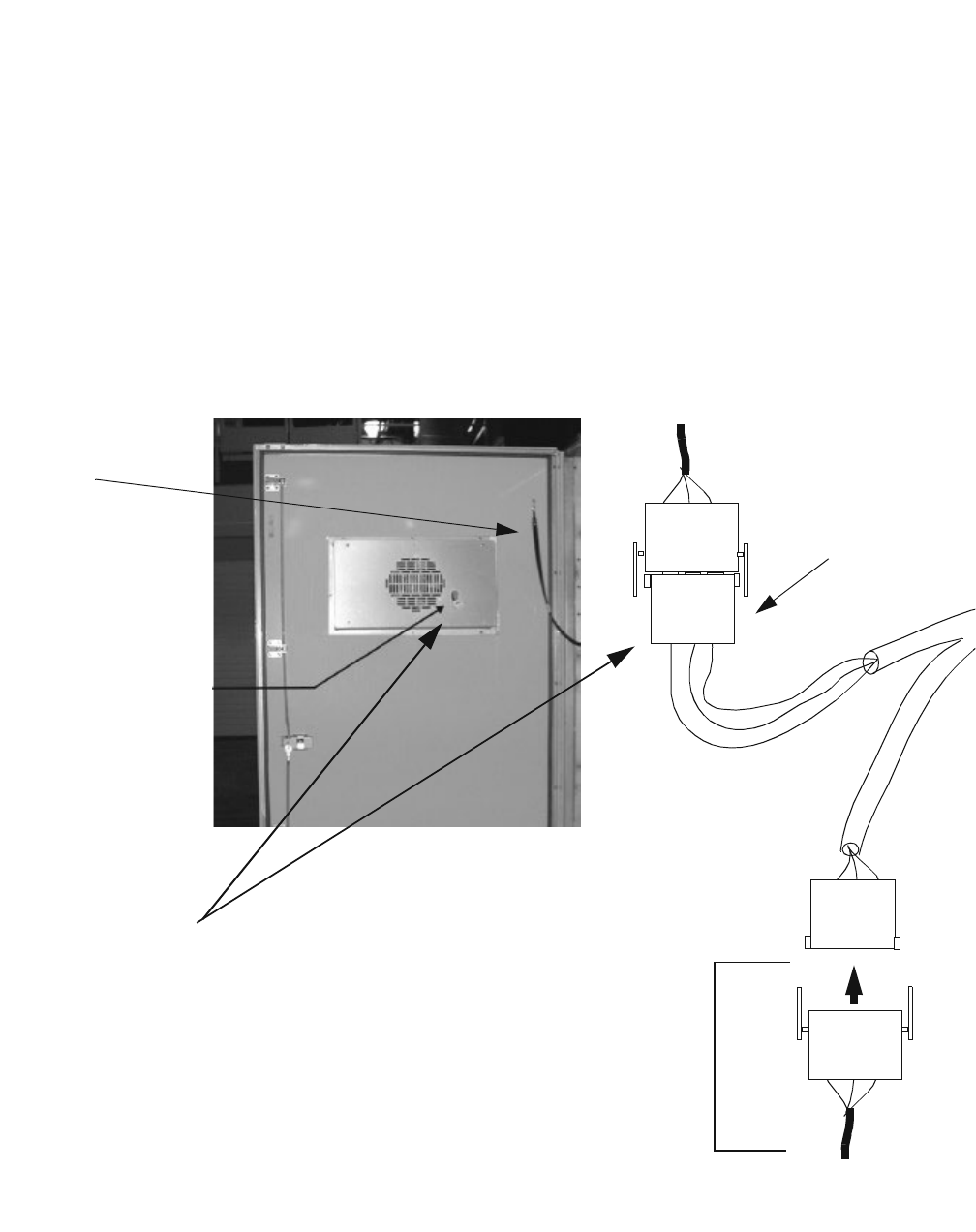
1Attach the fan power/alarm cable (labeled "J9") to "P9" in the first
WNG24-BC battery cabinet. Refer to the figure below.
................................................................................................................................
............................................
2Using wire ties, dress the fan power/alarm cables to the interior left side
of the first battery cabinet. Do this in such a way that they do not
interfere with door opening and closure, or installation/replacement of
parts.
GROUND
STRAP
P9
FAN
J9
"FAN" FOR
FIRST
WNG24-BC
BATTERY
CABINET FAN
(FROM POWER
CABINET)
FAN
POWER
CABLE
FROM
SECOND
BATTERY
CABINET

4-66 Lucent Technologies – Proprietary
See notice on first page 401-703-454
FOA Draft Issue 1
January, 2006
...........................................................................................................................................................................................................................................................
Power and power alarm connections in Modular Cell 4.0B
cabinets with integrated power
How to route and connect the AC power cable in the first battery
.............................................................................................................................................................................................................................................................
cabinet
DANGER
Electrical Shock Hazard
Failure to follow the order of the installation procedure (as
written) can result in an energized AC or DC circuit, which
creates an electrical shock hazard.
Follow these rules:
1. Make sure that the battery cabinet heater AC circuit
breaker, in the primary cabinet, is in the OFF position.
2. Perform installation steps in the order provided. Do not
connect AC power until instructed to do so.
3. Do not connect battery connectors.
4. Observe and strictly follow all safety precautions.
5. When completing electrical connections, always use
tools that are properly insulated.
Power and power alarm connections in Modular Cell 4.0B
cabinets with integrated power
4- 67
Lucent Technologies – Proprietary
See notice on first page
401-703-454
FOA Draft Issue 1
January, 2006
............................................................................................................................................................................................................................................................
Route the AC power cable
into the first WNG24-BC
battery cabinet
Perform the following steps to route the AC power cable into the first
WNG24-BC battery cabinet.
................................................................................................................................
............................................
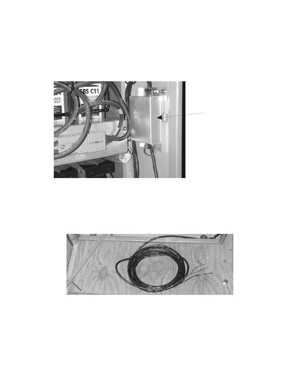
1The AC power cable is shipped already terminated at the AC junction
box in the second WNG24-BC battery cabinet. The AC power cable is
shipped coiled in the bottom of the battery cabinet. Refer to the figure
on Page 4 - 67 and the figure below.
................................................................................................................................
............................................
2Remove the AC power cable from the bottom of the second battery
cabinet and uncoil. Refer to the figure below.
A
C JUNCTION
BOX
4-68 Lucent Technologies – Proprietary
See notice on first page 401-703-454
FOA Draft Issue 1
January, 2006
...........................................................................................................................................................................................................................................................
Power and power alarm connections in Modular Cell 4.0B
cabinets with integrated power
................................................................................................................................
............................................
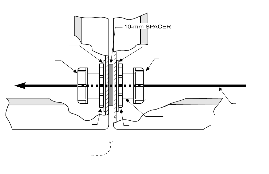
3Thread the AC power cable through the AC coupling into the first
WNG24-BC battery cabinet. Refer to the figure below.
................................................................................................................................
............................................
4Route the AC cable up the interior right wall of the first battery cabinet.
Refer to the figure on Page 4 - 69.
BOTTOM FRONT VIEW
SEALING WASHER*
AREA BETWEEN
CABINETS
LOCK NUT
2-inch
P
LASTIC BUSHING
SEALING WASHER
LOCK NUT
FIRST WNG24-BC
BATTERY CABINET
SECOND WNG24-BC
BATTERY CABINET
*(”BOX SIDE” FACING
CABINET WALL)
2-inch
FEED-THROUGH COUPLING
2-inch
PLASTIC BUSHING
AC POWE
R
CABLE
*
Power and power alarm connections in Modular Cell 4.0B
cabinets with integrated power
4- 69
Lucent Technologies – Proprietary
See notice on first page
401-703-454
FOA Draft Issue 1
January, 2006
............................................................................................................................................................................................................................................................
Connect AC cable in the
first WNG24-BC battery
cabinet
Perform the following steps to connect the second WNG24-BC battery
cabinet AC cable in the first WNG24-BC battery cabinet.
................................................................................................................................
............................................
1In the Modular Cell 4.0B primary cabinet, place the circuit breaker
"BATTERY HEATER" to the off position.
................................................................................................................................
............................................
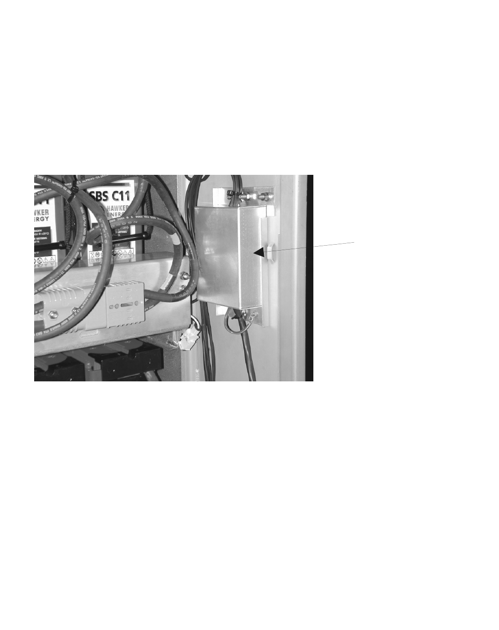
2Route the AC cable to the AC junction box in the first battery cabinet.
Refer to the figure below.
................................................................................................................................
............................................
3Remove the AC junction box cover.
................................................................................................................................
............................................
4Cut the AC cable to the desired length.
................................................................................................................................
............................................
5Remove the outer cable insulation to expose the individual wires and
strip 15 mm (3/8 inch) of insulation from each wire.
Important! When performing the next step, it may be necessary
to remove the entire AC junction box from the cabinet wall, in
order to access the screws for the black (left) wires.
AC JUNCTION
BOX
4-70 Lucent Technologies – Proprietary
See notice on first page 401-703-454
FOA Draft Issue 1
January, 2006
...........................................................................................................................................................................................................................................................
Power and power alarm connections in Modular Cell 4.0B
cabinets with integrated power
................................................................................................................................
............................................
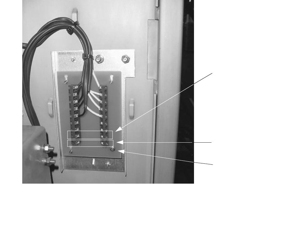
6Connect the wires of the AC cable to the terminal strip and the
grounding screw as follows. Refer to the figure below.
• Black (L1) to left terminal strip
• Red (L2) to right terminal strip
• Green to grounding screw
................................................................................................................................
............................................
7Replace the AC junction box cover.
................................................................................................................................
............................................
8Using wire ties, dress the AC cable in both cabinets so that it will not
interfere with door closure or installation/replacement of parts.
................................................................................................................................
............................................
9If not installing a growth cabinet at this time, skip to Chapter 5 to install
END OF STEPS
................................................................................................................................
.............................................
the batteries in the second battery cabinet, and reconnect DC power.
CONNECT AC FROM
SECOND BATTERY
CABINET HERE
AC FROM POWER
CABINET IS ALREADY
CONNECTED HERE
GROUND SCREW

Power and power alarm connections in Modular Cell 4.0B
cabinets with integrated power
4- 71
Lucent Technologies – Proprietary
See notice on first page
401-703-454
FOA Draft Issue 1
January, 2006
............................................................................................................................................................................................................................................................
How to install 60ECv2 battery cabinets with a 4.0B primary cabinet
.............................................................................................................................................................................................................................................................
with integrated power (reference)
How to install a first
60ECv2 battery cabinet
with a 4.0B primary cabinet
Refer to: Comcode 109559757, Interface Kit for Attachment of 60EC
or 60ECv2 Battery Cabinets to Modular Cell 3.0/4.0B Cabinets with
Integrated Power.
For general installation instructions, refer to the table below. For
changes in battery cables and bus bar wiring, refer to Current and revised
battery cables on Page 4 - 72 and Revised power wiring to the cabinet bus
bars on Page 4 - 74
How to install a second
60ECv2 battery cabinet
with a 4.0B primary cabinet
A second 60ECv2 battery cabinet may be installed with a first 60ECv2
battery cabinet using instruction provided in the Outdoor Flexent
Modular Cell 1.0/2.0 Cabinet Installation Manual, 401-710-123. Refer
to the chapter and revised battery cable references below:
Step-by-step instructions are provided in the following chapters of the
above document.
• Chapter 5:
•Battery cabinet optional mounting base installation
•Chapter 5B
•Second 60ECv2/60ECv2G battery cabinet installation
•Revisions to referenced Chapter 5B:
•Battery Cables
(Revisions to existing procedures in Chapter 5B of Flexent
Modular Cell Outdoor 1.0/2.0 Cabinet Installation Manual, 401-
710-123)
•Refer to Current and revised battery cables on Page 4 - 72 and
Revised power wiring to the cabinet bus bars on Page 4 - 74
Important! Note that the battery cable and bus bar wiring
revisions were made to reduce the battery installation time, and
cable congestion in the 66ECv2 battery cabinet
4-72 Lucent Technologies – Proprietary
See notice on first page 401-703-454
FOA Draft Issue 1
January, 2006
...........................................................................................................................................................................................................................................................
Power and power alarm connections in Modular Cell 4.0B
cabinets with integrated power
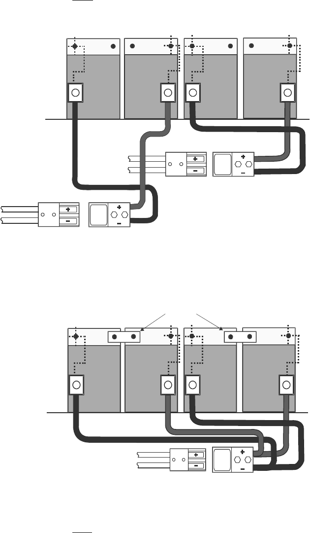
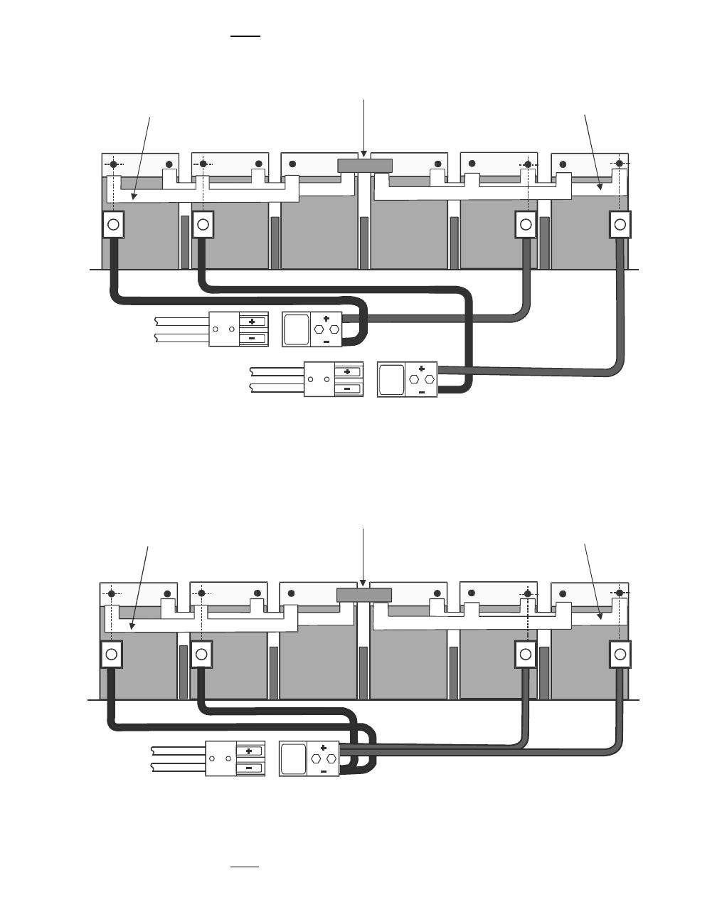
Current and revised battery
cables The following figures illustrate the current and revised battery cables
with both 12IR125 and SBS C11 batteries. Note that C11 battery
installation was not covered in the referenced document.
CURRENT 12IR125 BATTERY WIRING
Two quick-disconnect connectors.
REVISED 12IR125 BATTERY WIRING
One quick-disconnect connectors.
(-) (+) (-) (+)
(-)
(+)
(-)
(+)
Black (-)
Red (+)Black (-) Red (+)
J401
J401
J401
J401P401
P401
(-) (+) (-) (+) (-)
(+)
(-)
(+)
J401
J401
Black (-)
Red (+)Black (-) Red (+)
Bus Bars
P401
Power and power alarm connections in Modular Cell 4.0B
cabinets with integrated power
4- 73
Lucent Technologies – Proprietary
See notice on first page
401-703-454
FOA Draft Issue 1
January, 2006
............................................................................................................................................................................................................................................................
CURRENT SBS C11 BATTERY WIRING
Two quick-disconnect connectors.
REVISED SBS C11 BATTERY WIRING
One quick-disconnect connectors.
Inter-Battery
Bus Bar
(-) (+)
(-) (+) (-)
(+)
(-) (+)
(-)
(+)
(-)
(+)
Bus Bar Over
Negative Terminal Studs (-)
Bus Bar Over
Negative Terminal Studs (-)
J401
J401P401
J401
J401P401
Inter-Battery
Bus Bar
(-) (+)
(-) (+) (-)
(+)
(-) (+)
(-)
(+)
(-)
(+)
Bus Bar Over
Negative Terminal Studs (-)
Bus Bar Over
Negative Terminal Studs (-)
J401
J401P401
4-74 Lucent Technologies – Proprietary
See notice on first page 401-703-454
FOA Draft Issue 1
January, 2006
...........................................................................................................................................................................................................................................................
Power and power alarm connections in Modular Cell 4.0B
cabinets with integrated power
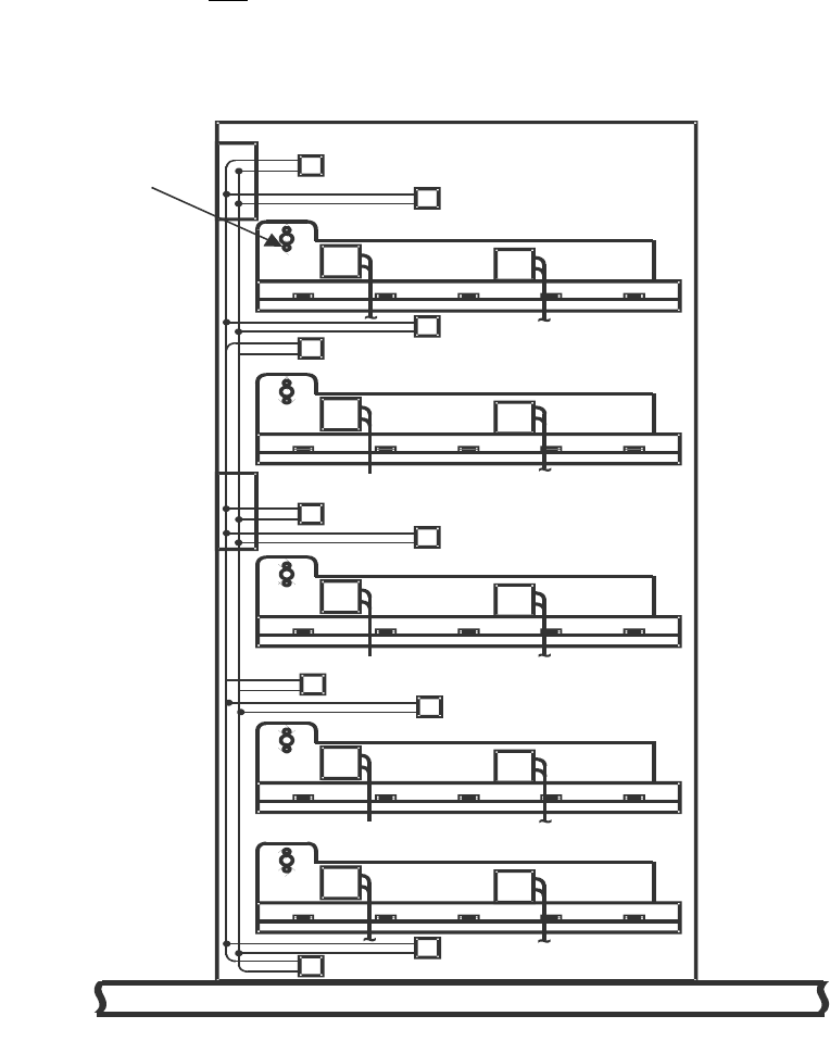
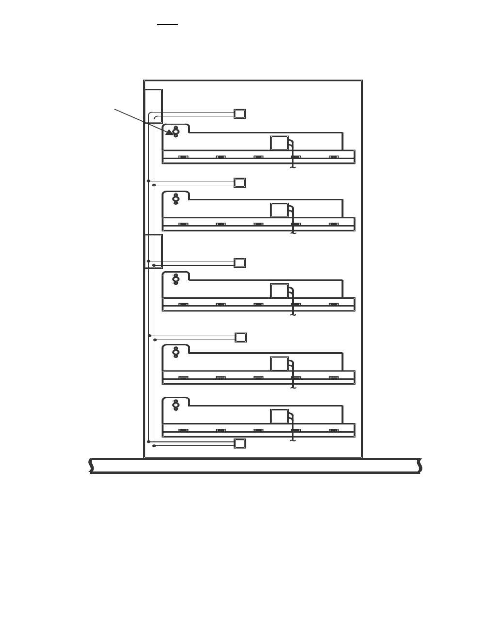
Revised power wiring to
the cabinet bus bars The following figures illustrate the current and revised factory installed
power wiring to the cabinet bus bars
CURRENT WIRING TO CABINET BUS BARS
Ten sets of battery cables to the bus bars
Battery Shelf 1
Battery Shelf 5
Battery Shelf 4
Battery Shelf 3
Battery Shelf 2
N
ut and Washer
(
1 Set of 10)
J401-2
P401-3
J401-4
J401-3
P401-5
P401-7
P401-9
J401-5
J401-1
~
~
~
+
-
P401-2
P401-10
P401-8
P401-6
P401-4
P401-1
Power and power alarm connections in Modular Cell 4.0B
cabinets with integrated power
4- 75
Lucent Technologies – Proprietary
See notice on first page
401-703-454
FOA Draft Issue 1
January, 2006
............................................................................................................................................................................................................................................................
CURRENT WIRING TO CABINET BUS BARS
Five sets of battery cables to the bus bars
Battery Shelf 1
Battery Shelf 5
Battery Shelf 4
Battery Shelf 3
Battery Shelf 2
N
ut and Washer
(
1 Set of 10)
P401-10
P401-8
P401-6
P401-4
P401-2
J401-2
J401-4
J401-3
J401-5
J401-1
4-76 Lucent Technologies – Proprietary
See notice on first page 401-703-454
FOA Draft Issue 1
January, 2006
...........................................................................................................................................................................................................................................................
Power and power alarm connections in Modular Cell 4.0B
cabinets with integrated power

5- 1
Lucent Technologies – Proprietary
See notice on first page
401-703-454
FOA Draft Issue 1
January, 2006
............................................................................................................................................................................................................................................................
5 Component installation in the
Modular Cell 4.0B and the
WNG24-BC battery cabinets
.............................................................................................................................................................................................................................................................
Overview
Purpose This chapter provides instructions for the installation of rectifiers in
integrated power Modular Cell 4.0B cabinets, and for the installation of
batteries in integrated power Modular Cell 4.0B cabinets and WNG24-
BC battery cabinets connected to primary cabinets. Also provided are
instructions for thermal probe installation and final connection of DC
cables after installation of batteries in a newly installed battery cabinet.
Contents This chapter contains the following sections.
How to install components in Modular Cell 4.0B cabinets 5 - 2
How to install batteries in a WNG24-BC battery cabinet 5 - 10
How to route the thermal probe cable(s) and mount the thermal probe(s) in the
battery cabinets
5 - 81
How to make final DC connections after installation of a battery cabinet 5 - 84

5-2 Lucent Technologies – Proprietary
See notice on first page 401-703-454
FOA Draft Issue 1
January, 2006
...........................................................................................................................................................................................................................................................
Component installation in the Modular Cell 4.0B and the
WNG24-BC battery cabinets
How to install components in Modular
Cell 4.0B cabinets
.............................................................................................................................................................................................................................................................
Overview
Purpose This section contains the following procedures.
How to install rectifiers in Modular Cell 4.0B cabinets 5 - 3
How to install batteries in Modular Cell 4.0B cabinets 5 - 5

Component installation in the Modular Cell 4.0B and the
WNG24-BC battery cabinets
5- 3
Lucent Technologies – Proprietary
See notice on first page
401-703-454
FOA Draft Issue 1
January, 2006
............................................................................................................................................................................................................................................................
.............................................................................................................................................................................................................................................................
How to install rectifiers in Modular Cell 4.0B cabinets
Install rectifiers in a
Modular Cell 4.0B primary
cabinet
The rectifiers required for a given cabinet configuration are shipped
already installed in the Modular Cell 4.0B cabinets. Rectifiers may
need to be added as part of a field upgrade, in which case the
instructions are included in the upgrade kit. These instructions are
provided for the convenience of the installer only. Perform the
following steps to install rectifiers in a Modular Cell 4.0B cabinet.
................................................................................................................................
............................................
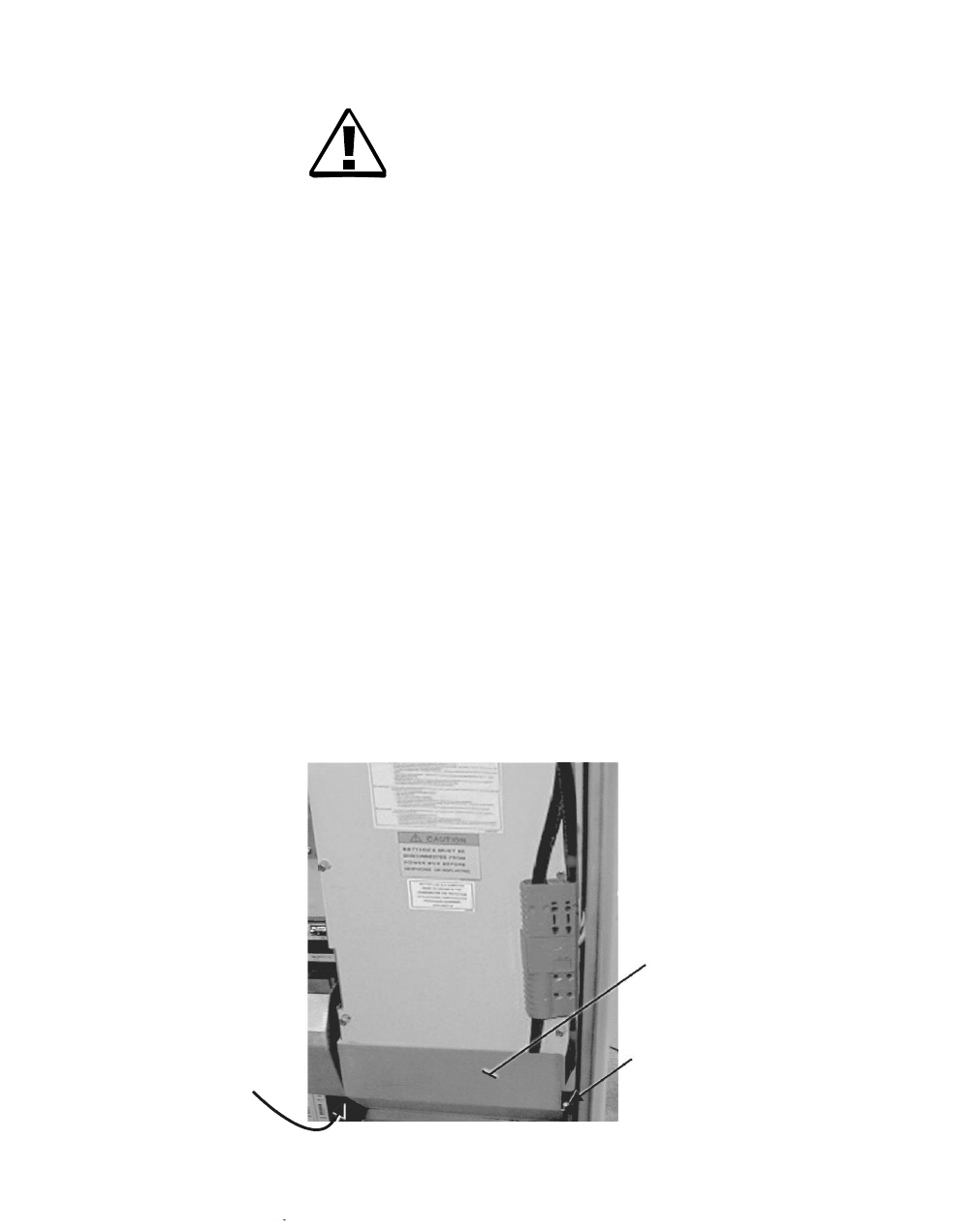
1Consult the following table to obtain the rectifier quantity required to
support the installation of the cabinet being installed, depending upon
the number of carriers, as well as the cabinet model and configuration.
................................................................................................................................
............................................
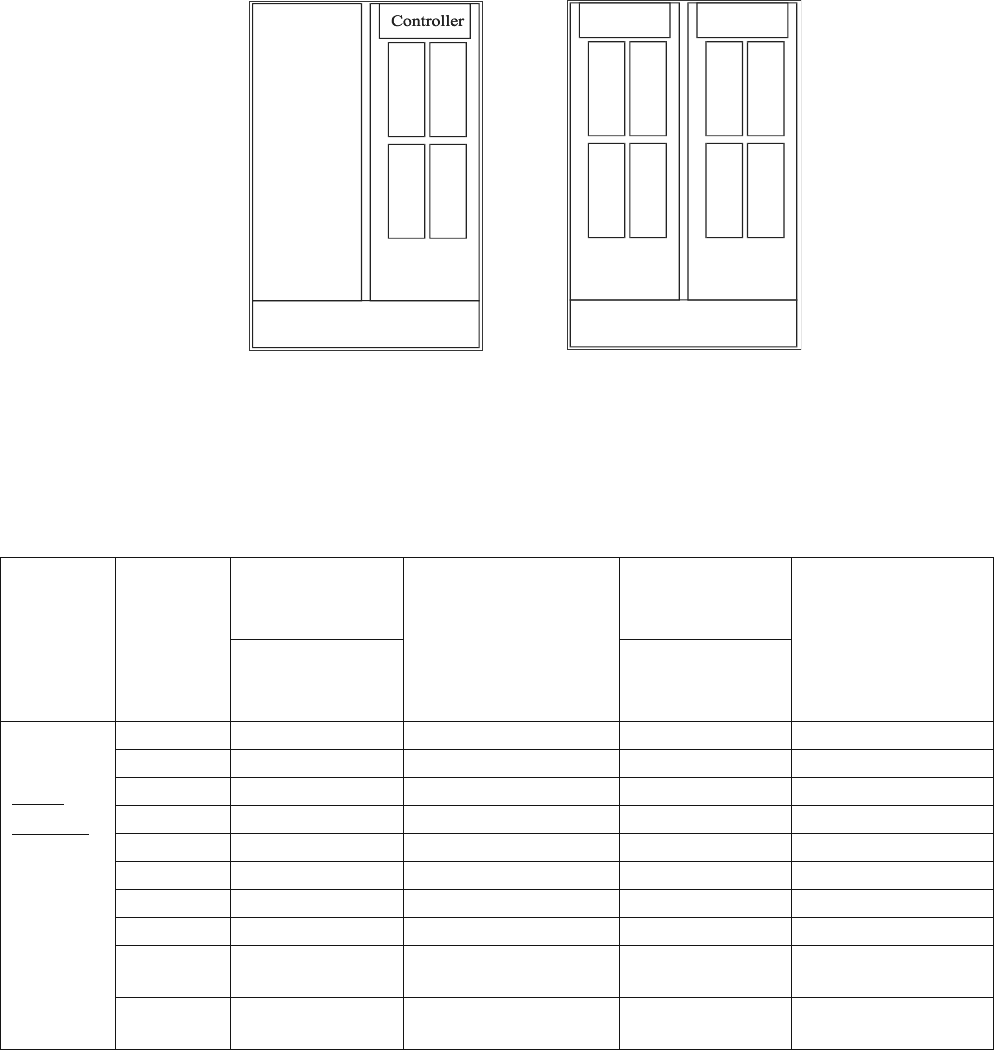
2The table on Page 5 - 4 identifies the rectifiers needed (N+1) for a PCS
or 850 Modular Cell 4.0B primary cabinet. Refer to the figure on Page
5-4 for rectifier positions.
................................................................................................................................
............................................
3When performing the following steps, install the rectifiers in the order
shown on the front of the AC module. Refer to the figure on Page 5-4.
................................................................................................................................
............................................
4Remove the blank rectifier panel, if applicable. Refer to the figure on
Page 5-4.
................................................................................................................................
............................................
5Slide the rectifier into the enclosure.Refer to the figure on Page 5-4.
5-4 Lucent Technologies – Proprietary
See notice on first page 401-703-454
FOA Draft Issue 1
January, 2006
...........................................................................................................................................................................................................................................................
Component installation in the Modular Cell 4.0B and the
WNG24-BC battery cabinets
................................................................................................................................
............................................
6Tighten the thumb screws.
1 2
3 4
ACPDA
Blank Plate
Integrated Power
Configuration
(up to 4 rectifiers)
1
2
3
4
ACPDA
Integrated Power
Configuration
(>5 rectifiers)
1 2
3 4
Primary
Rectifier
Shelf
Primary
Rectifier
Shelf
Auxiliary
Rectifier
Shelf
Auxiliary
Controller
Primary
Controller
Modular
Cell
4.0B
cabinet
Total
carriers
Rectifiers
needed per
cabinet (N+1)
Rectifier positions
for PCS
P = Primary
Controller.
A = Auxiliary
Controller
Rectifiers
needed per
cabinet (N+1)
Rectifier
positions for 850
P = Primary
Controller.
A = Auxiliary
Controller
PCS 850
Modular
Cell
4.0B
Primary
Cabinet
1 3 1,2,3 P 3 1,2,3 P
2 3 1,2,3 P 3 1,2,3 P
3 4 1,2,3,4 P 4 1,2,3,4 P
4 5 1,2,3,4 P / 1 A 4 1,2,3,4 P
5 5 1,2,3,4 P / 1 A 5 1,2,3,4 P / 1 A
6 6 1,2,3,4 P / 1,2 A 5 1,2,3,4 P / 1 A
7 7 1,2,3,4 P / 1,2,3 A 6 1,2,3,4 P / 1,2 A
8 7 1,2,3,4 P / 1,2,3 A N/A N/A
9
(
PCS only)
8 1,2,3,4 P / 1,2,3,4 A N/A N/A
10
(
PCS only)
8 1,2,3,4 P / 1,2,3,4 A N/A N/A
Component installation in the Modular Cell 4.0B and the
WNG24-BC battery cabinets
5- 5
Lucent Technologies – Proprietary
See notice on first page
401-703-454
FOA Draft Issue 1
January, 2006
............................................................................................................................................................................................................................................................
.............................................................................................................................................................................................................................................................
How to install batteries in Modular Cell 4.0B cabinets
CAUTION
Damage to equipment
The battery cables in the primary cabinet must not be
connected until after the AC utility wires are connected and
AC power is turned on at the main panel. Do not connect the
battery cables until instructed to do so in Chapter 7
"Finishing the installation".
Install batteries in a
Modular Cell 4.0B cabinet The batteries required for a given cabinet configuration are shipped
already installed in the Modular Cell 4.0B primary cabinet. Under
certain circumstances, batteries may need to be installed. These
instructions are provided for the convenience of the installer. Perform
the following steps to remove and install batteries in a Modular Cell
4.0B cabinet.
................................................................................................................................
............................................
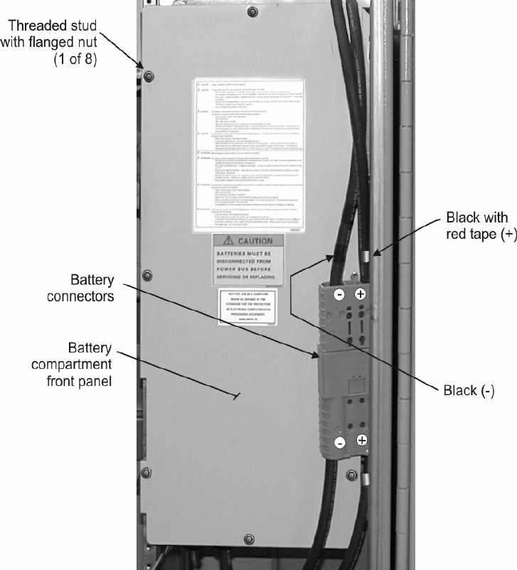
1Remove the two bolts shown in the figure below, and remove the air
baffle from above the rectifier module.
MOUNTING BOLT
LOCATION
RECTIFIER
BAFFLE
MOUNTING BOLT
5-6 Lucent Technologies – Proprietary
See notice on first page 401-703-454
FOA Draft Issue 1
January, 2006
...........................................................................................................................................................................................................................................................
Component installation in the Modular Cell 4.0B and the
WNG24-BC battery cabinets
................................................................................................................................
............................................
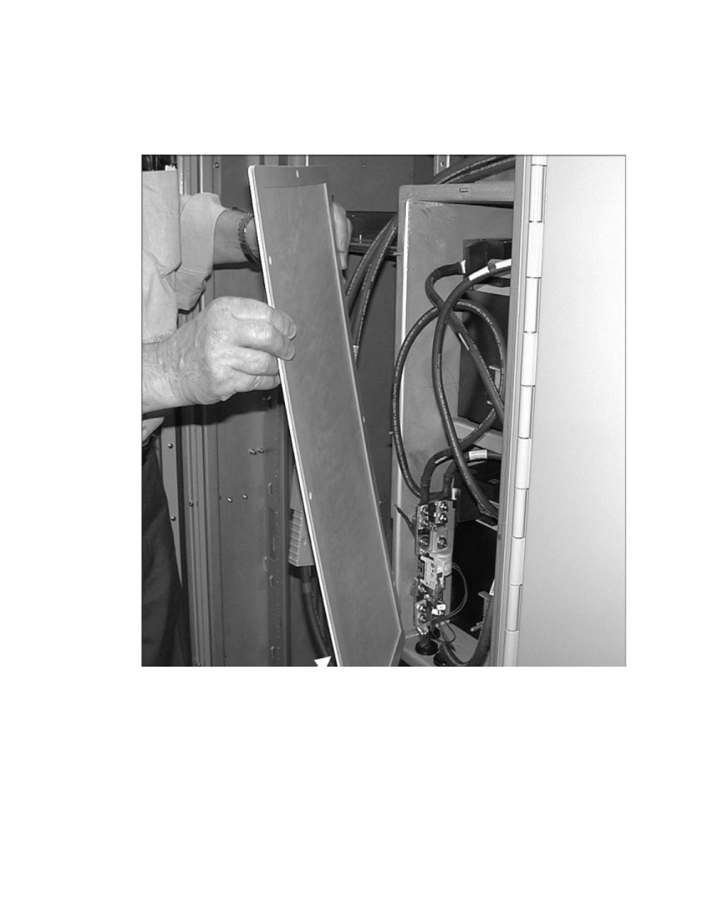
2Unplug the battery connectors. Refer to the figure below.
................................................................................................................................
............................................
3Remove the eight flanged nuts that hold the battery front panel in place.
Refer to the figure on Page 5-7.
Component installation in the Modular Cell 4.0B and the
WNG24-BC battery cabinets
5- 7
Lucent Technologies – Proprietary
See notice on first page
401-703-454
FOA Draft Issue 1
January, 2006
............................................................................................................................................................................................................................................................
................................................................................................................................
............................................
4Remove the battery module front panel. Refer to the figure below.
................................................................................................................................
............................................
5Lay aside the battery compartment front panel.
................................................................................................................................
............................................
6Remove the top spacer from the applicable shelf. Refer to the figure on
Page 5-8.
................................................................................................................................
............................................
7Unscrew the nut and remove the battery retaining bracket.
................................................................................................................................
............................................
8Remove the interconnecting bus bar.
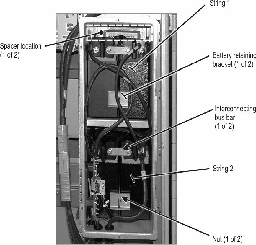
5-8 Lucent Technologies – Proprietary
See notice on first page 401-703-454
FOA Draft Issue 1
January, 2006
...........................................................................................................................................................................................................................................................
Component installation in the Modular Cell 4.0B and the
WNG24-BC battery cabinets
................................................................................................................................
............................................
9Remove the positive and negative battery cables from the batteries, and
the two batteries from the shelf.
................................................................................................................................
............................................
10 Install the batteries by reversing the previous four steps. Refer to the
figure below. Carefully observe the polarity while reconnecting the
battery cables.
Component installation in the Modular Cell 4.0B and the
WNG24-BC battery cabinets
5- 9
Lucent Technologies – Proprietary
See notice on first page
401-703-454
FOA Draft Issue 1
January, 2006
............................................................................................................................................................................................................................................................
................................................................................................................................
............................................
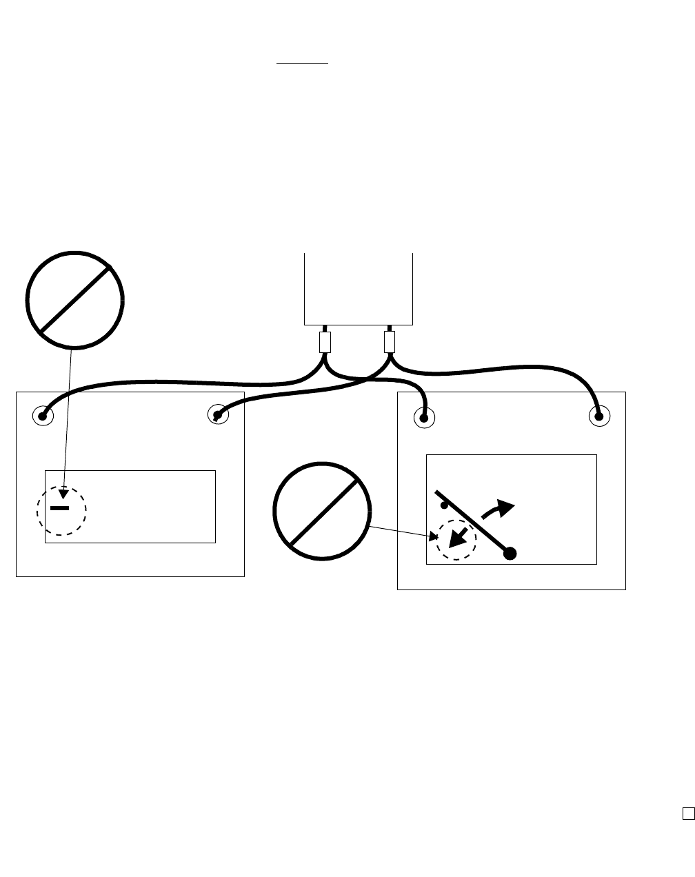
11 Measure the voltage at the battery cable external connector to determine
that the polarity is correct. Refer to the figure below.
• Digital meter - no symbol or positive symbol = correct
connection.
• Digital meter - negative symbol = incorrect connection.
• Analog meter - positive deflection = correct connection.
• Analog meter - negative deflection = incorrect connection.
All of the above assume correct meter lead connection.
................................................................................................................................
............................................
12 If necessary, rewire the battery cables found to be incorrectly wired.
................................................................................................................................
............................................
13 Replace the front panel and air baffle.
................................................................................................................................
............................................
END OF STEPS
................................................................................................................................
.............................................
14 Reconnect the battery connector.
+
_
+
_
26.25*
+
_
NEGATIVE
SYMBOL
POSITIVE
DEFLECTION
NEGATIVE
DEFLECTION
ANALOG
DIGITAL
BATTERY
CONNECTOR *EXAMPLE VOLTAGE ONLY

5-10 Lucent Technologies – Proprietary
See notice on first page 401-703-454
FOA Draft Issue 1
January, 2006
...........................................................................................................................................................................................................................................................
Component installation in the Modular Cell 4.0B and the
WNG24-BC battery cabinets
How to install batteries in a
WNG24-BC battery cabinet
.............................................................................................................................................................................................................................................................
Overview
Purpose This section provides the instructions for the installation and
connection of the batteries. The instructions are the same for both a first
or second battery cabinet, except in the case of thermal probes, where
the exceptions are noted.
Important! If installing an EZBFo battery module, proceed to
Appendix A.
This section contains the following procedures.
Contents
How to determine battery shelf type 5 - 15
How to install L1, L2, and 12IR125 batteries on type 1 battery
shelves
5 - 16
How to install C-11 batteries on type 1 battery shelves 5 - 32
How to install 12IR125 type batteries on type 2 battery shelves 5 - 49
How to install C-11 type batteries on type 2 battery shelves 5 - 63

Component installation in the Modular Cell 4.0B and the
WNG24-BC battery cabinets
5- 11
Lucent Technologies – Proprietary
See notice on first page
401-703-454
FOA Draft Issue 1
January, 2006
............................................................................................................................................................................................................................................................
.............................................................................................................................................................................................................................................................
Battery safety and
precautions Your understanding of the following information is important to ensure
a proper and safe installation of the batteries.
CAUTION
To batteries in this product can present a risk of high short
circuit and fire. The following precautions should be observed
when working on batteries:
•Remove watches, rings, or other metal objects
•Use insulated tools
•Wear rubber gloves and boots
•Disconnect charging source prior to connecting or
disconnecting battery terminals
DANGER
Injury to Personnel - Chemical Burns
The batteries contain electrolyte (sulfuric acid and water),
which can generate hydrogen gas, even under open circuit
conditions. Extreme caution must be taken when handling
batteries. Carefully follow all applicable procedures.

5-12 Lucent Technologies – Proprietary
See notice on first page 401-703-454
FOA Draft Issue 1
January, 2006
...........................................................................................................................................................................................................................................................
Component installation in the Modular Cell 4.0B and the
WNG24-BC battery cabinets
WARNING
Injury to Personnel
Lifting of the batteries by one person can result in a serious
injury. Always use two people (or use a lifting device) to
handle the batteries.
WARNING
High Energy hazard
The following procedures are the safest method to install and
connect the batteries. If these procedures are not followed in
the exact sequence listed, a serious electrical shock hazard
will result. Ensure that loose cables cannot cause a short
circuit. Since the batteries are charged, do not touch battery
terminals or cross terminals with metal objects. Do not
remove the insulated cover from the battery terminals until
you are preparing to complete each connection.
CAUTION
To reduce the risk of fire or injury to persons, read and follow
these instructions:
•Use only batteries approved for use with this product.
Refer to Approved batteries on Page 5 - 14 for the list of
approved batteries
Component installation in the Modular Cell 4.0B and the
WNG24-BC battery cabinets
5- 13
Lucent Technologies – Proprietary
See notice on first page
401-703-454
FOA Draft Issue 1
January, 2006
............................................................................................................................................................................................................................................................
•Do not dispose of the batteries in a fire. The cell may
explode. Check with local codes for possible disposal
instructions
•Do not open or mutilate the batteries. Released
electrolyte is corrosive and may cause damage to the eye
and skin. It may be toxic if swallowed
•Exercise care in handling batteries in order not to short
the battery with conductive materials such as rings,
bracelets, and keys. The battery or conductor may
overheat and cause burns
•Do not mix old and new batteries in this product.
Description of the battery
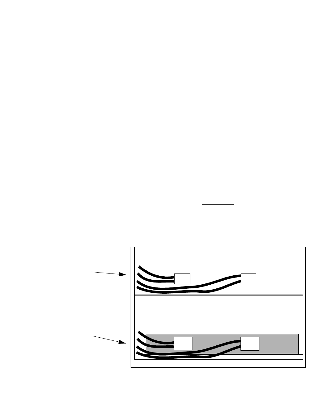
compartment The battery cabinet provides facilities to support five shelves of
batteries. The bottom shelf (shelf 1) is the initial shelf for installation
purposes. Each shelf provides space for four 12IR125 batteries (two
strings) or six C-11 batteries (one string). During installation, batteries
will be connected together to form strings. Battery heaters are located
under each shelf. Battery heater thermostats are present for each battery
shelf. The battery compartment has battery cables preinstalled from the
bus bars for all five shelves. For type 1 shelves, the bus bar cable
connectors are not attached to the uninstalled retaining brackets. For
type 2 shelves, the bus bar cable connectors are attached to the installed
retaining brackets. Refer to the figure below.
TYPE 2 BATTERY SHELF
EXAMPLE: BUS BAR
CONNECTORS
CONNECTED TO
INSTALLED RETAINING
BRACKET (1 of 5)
SHELF 1
SHELF 2
TYPE 1 BATTERY
SHELF EXAMPLE:
BUS BAR CONNECTORS
NOT CONNECTED TO
LOOSE RETAINING
BRACKET (1 of 5)

5-14 Lucent Technologies – Proprietary
See notice on first page 401-703-454
FOA Draft Issue 1
January, 2006
...........................................................................................................................................................................................................................................................
Component installation in the Modular Cell 4.0B and the
WNG24-BC battery cabinets
Approved batteries The following batteries are approved for use in the WNG24-BC battery
cabinet.
QUANTITY WNG24 - BC SHELF
TYPE BATTERY TYPE
As required per
site
specification
and battery type
Shelf type 1 Power CSL-12100 L1-type batteries
Shelf type 1 Marathon GNB M12V100FT L1-type
batteries
Shelf types 1 and 2 12IR125
Shelf types 1 and 2 C-11
Component installation in the Modular Cell 4.0B and the
WNG24-BC battery cabinets
5- 15
Lucent Technologies – Proprietary
See notice on first page
401-703-454
FOA Draft Issue 1
January, 2006
............................................................................................................................................................................................................................................................
.............................................................................................................................................................................................................................................................
How to determine battery shelf type
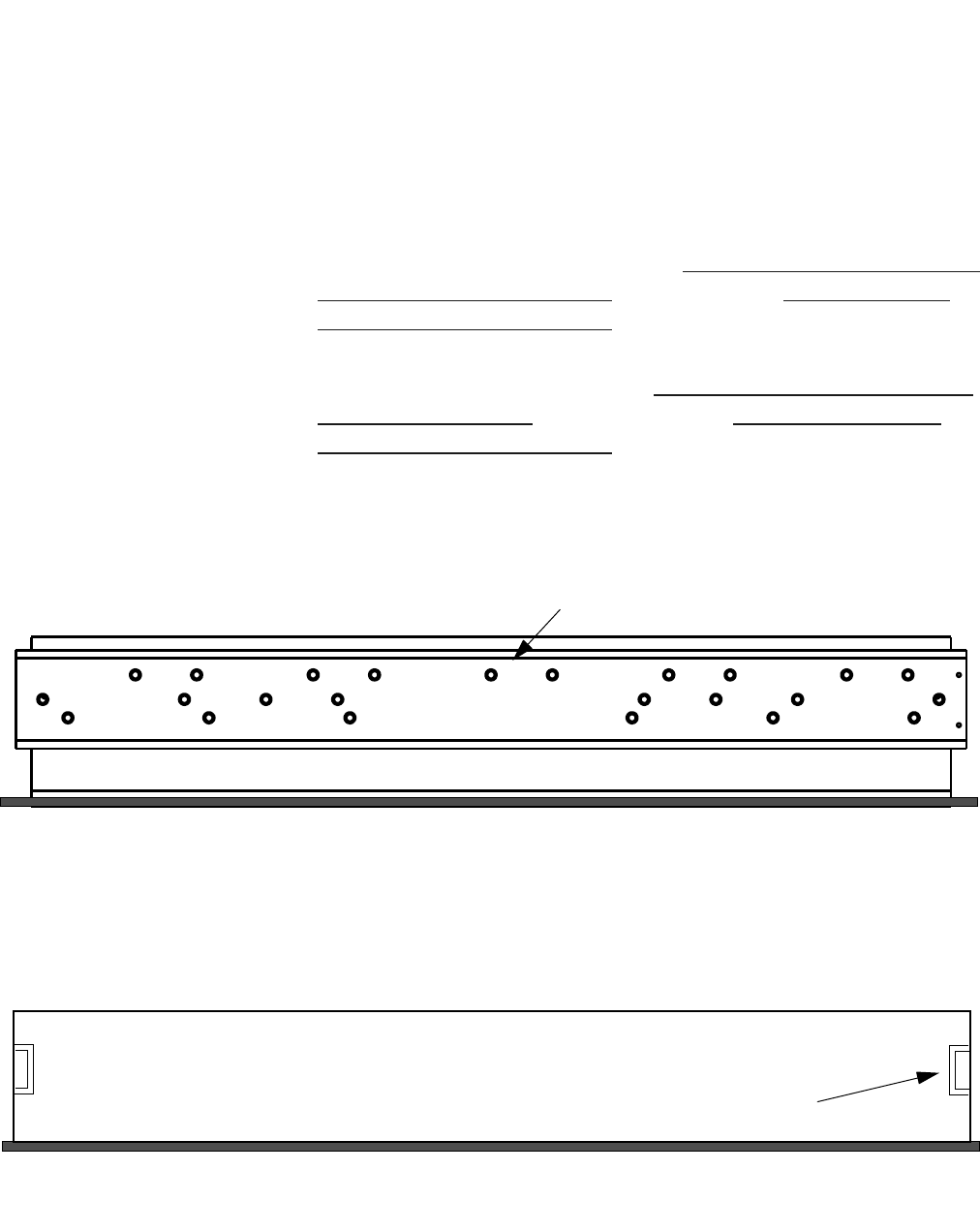
Overview Before proceeding to battery installation, it is necessary to determine
the specific battery shelf, type 1 or type 2, that is installed in the
WNG24-BC battery cabinet. The following figures illustrate both
battery shelves. Note that type 1 shelves have twenty-four threaded
holes in the rear shelf bracket, while the type 2 shelf has none.
If the battery shelf is type 1, proceed to How to install L1, L2, and 12IR125
batteries on type 1 battery shelves on Page 5 - 16 or How to install C-11
batteries on type 1 battery shelves on Page 5 - 32 to continue the
installation.
If the battery shelf is type 2, skip to How to install 12IR125 type batteries
on type 2 battery shelves on Page 5 - 49, or to How to install C-11 type
batteries on type 2 battery shelves on Page 5 - 63, as applicable, to
continue the installation.
Type 1 shelf
Type 2 shelf
REAR SHELF BRACKET
THREADED HOLES
REAR SHELF BRACKET
NO HOLES
SIDE RAIL (1 of 2)

5-16 Lucent Technologies – Proprietary
See notice on first page 401-703-454
FOA Draft Issue 1
January, 2006
...........................................................................................................................................................................................................................................................
Component installation in the Modular Cell 4.0B and the
WNG24-BC battery cabinets
.............................................................................................................................................................................................................................................................
How to install L1, L2, and 12IR125 batteries on type 1 battery shelves
Overview This section provides instructions for the installation and connection of
L1, L2, and 12IR125 batteries on type 1 battery shelves. The
instructions are the same for both a first or second battery cabinet (that
have type 1 shelves), except in the case of thermal probes, where the
exceptions are noted. This section contains the following procedures
Read battery installation
procedure overview Important! In the event that the battery compartment is
removed from the primary cabinet because of an upgrade that adds
the A6 amplifier shelf (carriers 5 and 6), up to four spare L1
batteries will result. The end user may wish to use these batteries
in the battery cabinet, in which case a shelf must be left vacant.
Therefore, while performing any task involving a type 1 top
battery shelf (shelf 5), it may be desirable to plan on leaving that
shelf empty when installing the batteries.
The battery cabinet can contain up to twenty L1, L2, or 12IR125
batteries that are wired in a series/parallel configuration which provides
24-volt backup. For L1, L2, or 12IR125 batteries, two strings (four
batteries) can be mounted on each of the five type 1 battery shelves.
Refer to the figure on Page 5-18.
Prepare the batteries for
installation To prepare the batteries, follow all appropriate standard practices for
the storage and handling of batteries. Complete the warranty
procedures and the following steps.
Place the batteries on a shelf 5 - 18
Install the battery retaining bracket 5 - 21
Attach the two battery cable assemblies to the retaining
bracket (L1,L2, and 12IR125 batteries only)
5 - 23
Examples of L1 and L2 battery shelf positions 5 - 24
Connect positive battery cables to all battery strings 5 - 26
Attach interconnecting bus bars to all battery strings 5 - 28
Connect the negative battery cables to all battery strings 5 - 30
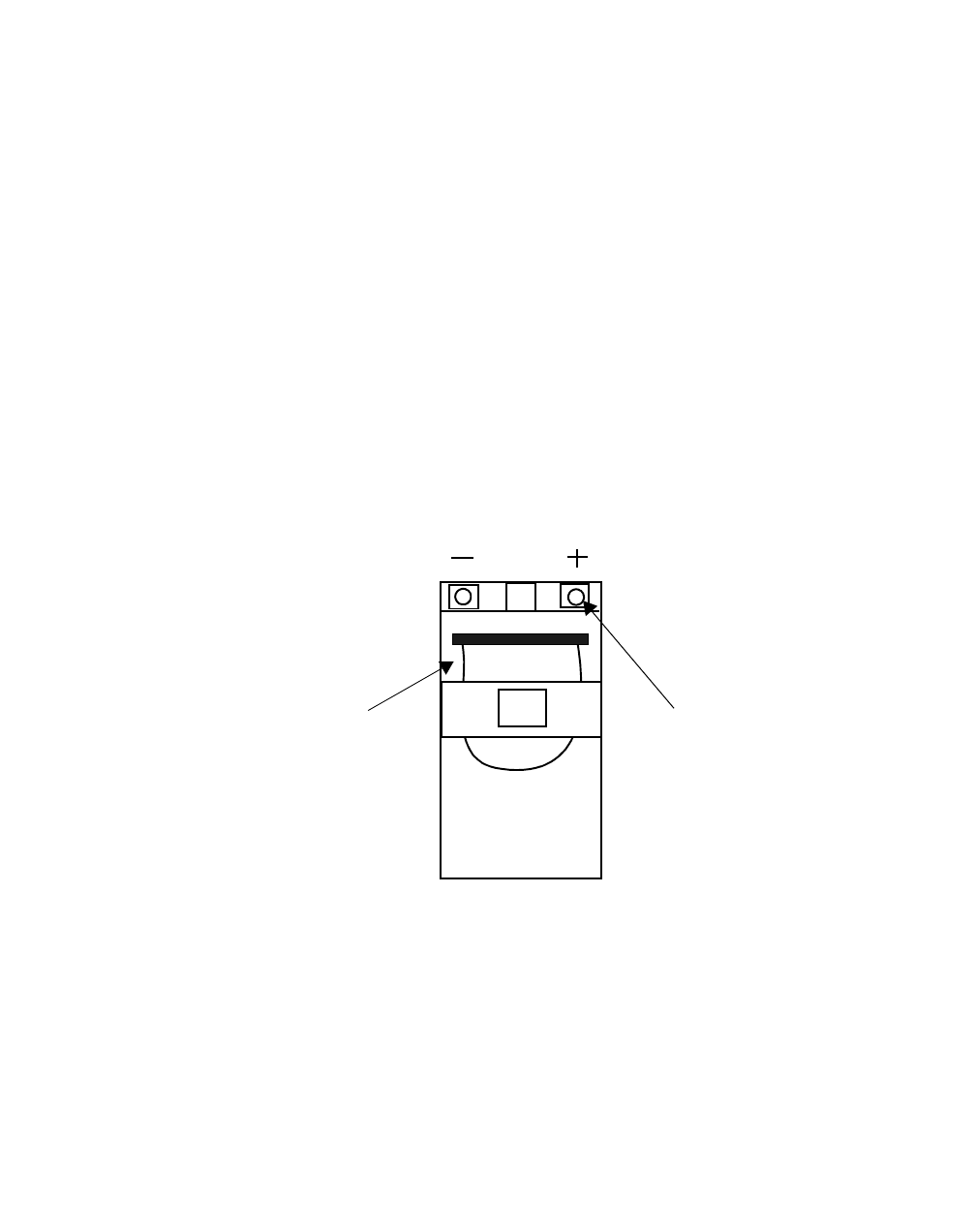
Component installation in the Modular Cell 4.0B and the
WNG24-BC battery cabinets
5- 17
Lucent Technologies – Proprietary
See notice on first page
401-703-454
FOA Draft Issue 1
January, 2006
............................................................................................................................................................................................................................................................
................................................................................................................................
............................................
1Check and record battery initial voltages and all battery date codes.
................................................................................................................................
............................................
2Include this information with documentation supplied to the customer.
END OF STEPS
................................................................................................................................
.............................................
Description of the batteries
The battery terminals are located on one end of the battery. Positive and
negative terminals are clearly labeled “+” and “-”. Terminals are either
threaded studs or threaded holes, depending upon the battery type.
Strap handles are permanently attached to the battery. Refer to the
example figure below.
Important! To prevent an inadvertent electrical short during
battery installation, certain battery types have an insulated cover
that is factory-installed over the terminals on the individual
batteries. Do not remove this cover until you are preparing to
complete each connection.
BATTERY
STRAP
NUT or BOLT
FOR
BATTERY
CABLE
ATTACHMENT
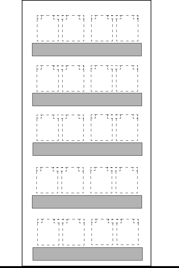
5-18 Lucent Technologies – Proprietary
See notice on first page 401-703-454
FOA Draft Issue 1
January, 2006
...........................................................................................................................................................................................................................................................
Component installation in the Modular Cell 4.0B and the
WNG24-BC battery cabinets
The figure below illustrates the battery string positions and battery
numbers for L1, L2, and 12IR125 batteries on type 1 shelves.
Place the batteries on a
shelf Use the following procedure to place batteries on a shelf, starting with
shelf 1 (bottom).
BATTERY-
SHELF 5
BATTERY-
SHELF 3
BATTERY-
SHELF 1
FRONT VIEW
STRING 5 STRING 6
STRING 3 STRING 4
STRING 1 STRING 2
STRING 7 STRING 8
STRING 9 STRING 10
BATTERY-
SHELF 4
BATTERY-
SHELF 2
-
+
+
--
+
+
-
12 12
-
+
+
--
+
+
-
12 12
-
+
+
--
+
+
-
12 12
-
+
+
--
+
+
-
12 12
-
+
+
--
+
+
-
12 12
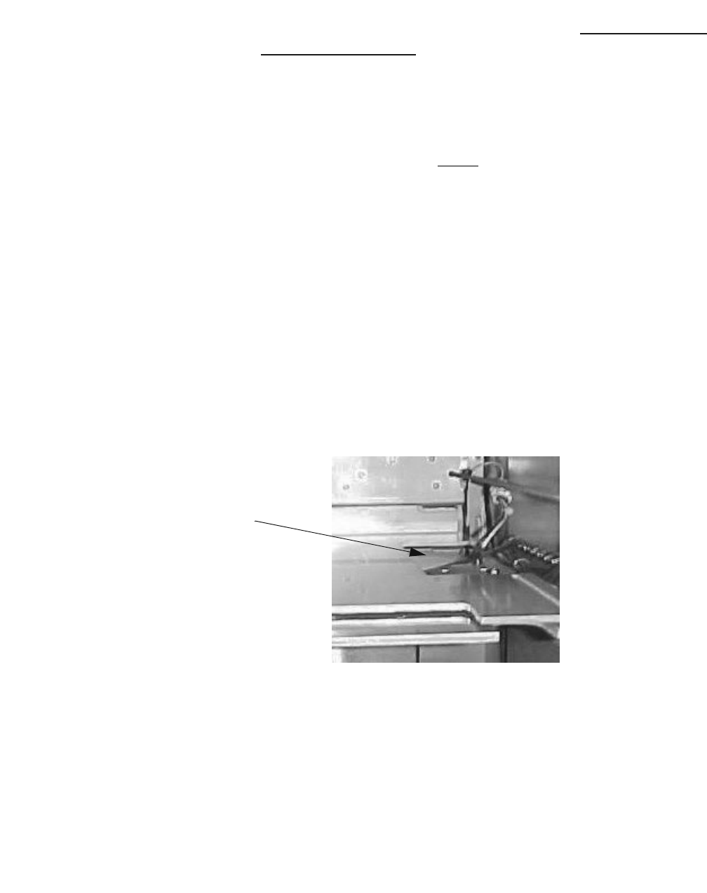
Component installation in the Modular Cell 4.0B and the
WNG24-BC battery cabinets
5- 19
Lucent Technologies – Proprietary
See notice on first page
401-703-454
FOA Draft Issue 1
January, 2006
............................................................................................................................................................................................................................................................
Important! This procedure, and the illustrations it contains,
uses 12IR125 batteries as an example. Refer to Examples of L1 and
L2 battery shelf positions on Page 5 - 24 for examples of L1 and L2
battery shelf positions.
................................................................................................................................
............................................
1Locate the 25 threaded rods shipped with the cabinet. Five will be used
per shelf. Thread a rod into the center hole of the rear bracket as shown
in the Step 5 figure on Page 5- 20, item 1.
Important! To avoid damage to the heater pad and wires when
performing the next step, the right-hand (or right-most) battery
(especially 12IR125 and C-11 types) should be tilted forward (at
the front of the shelf) as it is slid onto the shelf. Refer to the figure
below for the heater pad location.
................................................................................................................................
............................................
2When installed, the battery terminals on the front, narrow end of the
battery should face out of the cabinet. Slide two batteries onto the shelf,
one on each side of the center threaded rod. Refer to the figure on Page
5-20, item 2.
................................................................................................................................
............................................
3Thread a rod into the appropriate hole on the outside of the two batteries
installed in the previous step. Refer to the figure on Page 5-20,
item 3.
................................................................................................................................
............................................
4Slide two batteries onto the shelf, one on each side of the threaded rods
installed in the previous step. Refer to the figure on Page 5-20, item 4.
H
EATER PAD
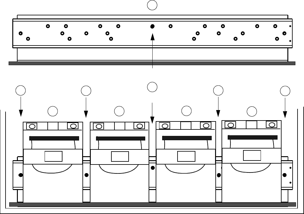
5-20 Lucent Technologies – Proprietary
See notice on first page 401-703-454
FOA Draft Issue 1
January, 2006
...........................................................................................................................................................................................................................................................
Component installation in the Modular Cell 4.0B and the
WNG24-BC battery cabinets
................................................................................................................................
............................................
5Thread a rod into the appropriate hole on the outside of the two batteries
installed in the previous step. Refer to the figure below, item 5.
................................................................................................................................
............................................
6Repeat Steps 1 through 6 for all battery shelves to be populated.
Important! Up to four batteries may be subsequently removed
from the primary cabinet. Therefore, it may be desirable to
provide future space for these batteries by leaving the top battery
cabinet shelf empty when installing the batteries in the following
steps.
................................................................................................................................
............................................
7Carefully wrap and store the remaining threaded rods, retaining bracket
and associated hardware on all shelves not being populated with
batteries at this time.
2
CENTER THREADED HOLE
REAR SHELF BRACKET
2
3
3
4
4
55
1
1
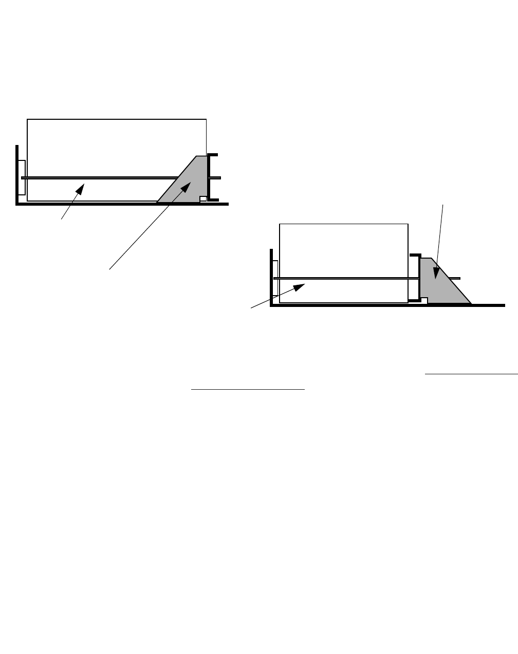
Component installation in the Modular Cell 4.0B and the
WNG24-BC battery cabinets
5- 21
Lucent Technologies – Proprietary
See notice on first page
401-703-454
FOA Draft Issue 1
January, 2006
............................................................................................................................................................................................................................................................
Install the battery retaining
bracket Perform the following steps to install the battery retaining bracket.
................................................................................................................................
............................................
1Preposition the retaining bracket in position 1 for L1 and L2 batteries,
or position 2 for 12IR125 batteries, as applicable. Refer to the figure
below.
Important! This procedure, and the illustrations it contains,
uses 12IR125 batteries as an example. Refer to Examples of L1 and
L2 battery shelf positions on Page 5 - 24 for examples of L1 and L2
battery shelf positions.
................................................................................................................................
............................................
2Slide the retaining bracket over the installed threaded rods.
L1 and L2
12IR125
LEFT SIDE VIEWS
BATTERIES
BATTERIES
RETAINING
BRACKET
(POSITION 1)
RETAINING
BRACKET
(POSITION 2)
THREADED ROD
(1 0f 5)
THREADED ROD
(1 of 5)
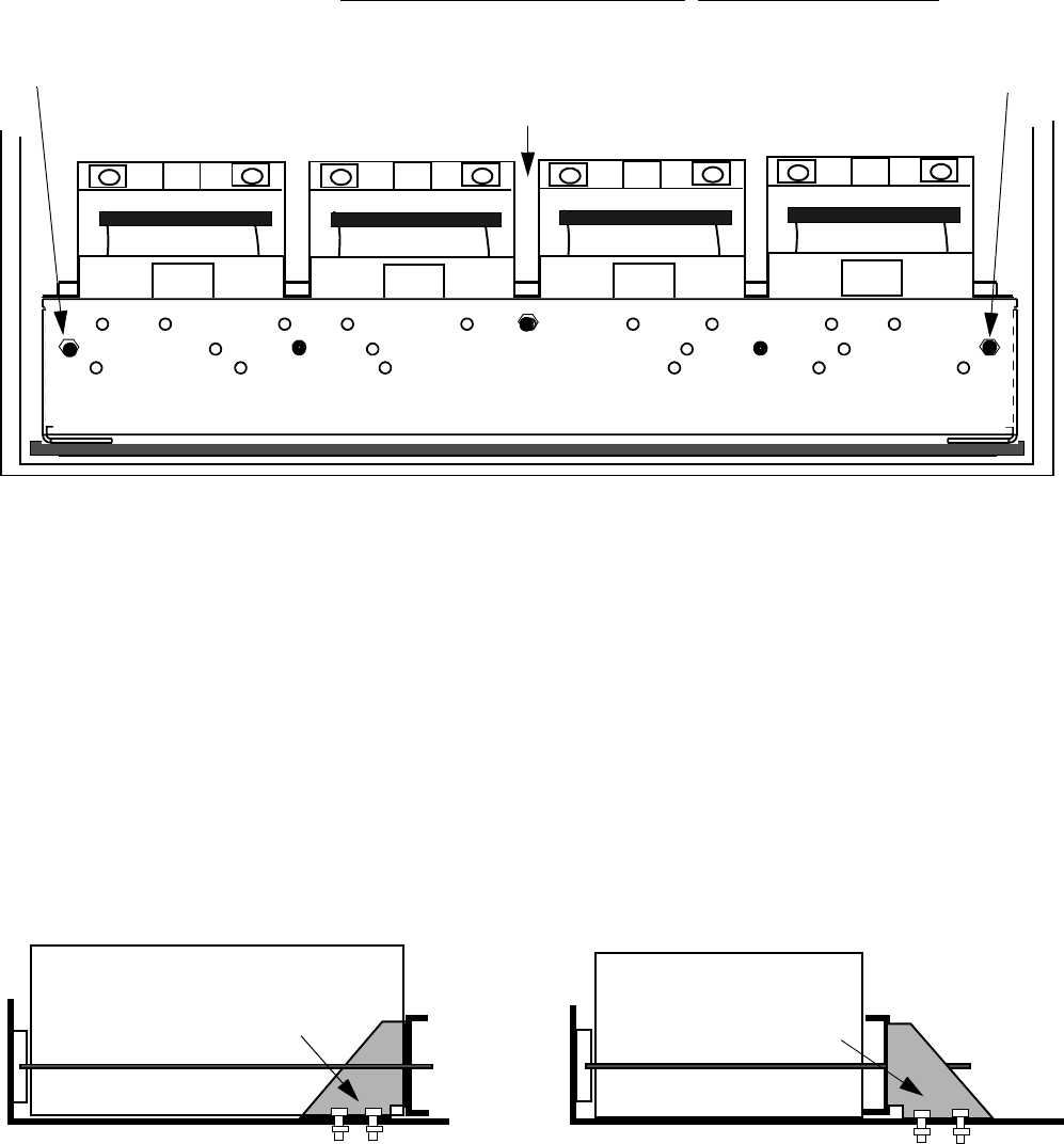
5-22 Lucent Technologies – Proprietary
See notice on first page 401-703-454
FOA Draft Issue 1
January, 2006
...........................................................................................................................................................................................................................................................
Component installation in the Modular Cell 4.0B and the
WNG24-BC battery cabinets
................................................................................................................................
............................................
3Using the nuts and washers provided, attach the retaining bracket at the
center and end threaded rods only. Do not tighten the nuts.
................................................................................................................................
............................................
4Using the supplied bolts, washers and nuts, attach the retaining bracket
to the shelf. Four sets of hardware are used, two on each side of the
bracket. Refer to the figure below.
................................................................................................................................
............................................
5Repeat Steps 1 through 4 for all populated battery shelves.
CENTER
THREADED ROD
END THREADED ROD
END THREADED ROD
RETAINING BRACKET
12IR125
LEFT SIDE VIEWS
RETAINING
BRACKET
(POSITION 1)
BATTERIES
L1 and L2
RETAINING
BRACKET
(POSITION 2)
BATTERIES 12IR125
BOLTS AND NUTS FOR
RETAINING BRACKETS
BOLTS AND NUTS FOR
RETAINING BRACKETS
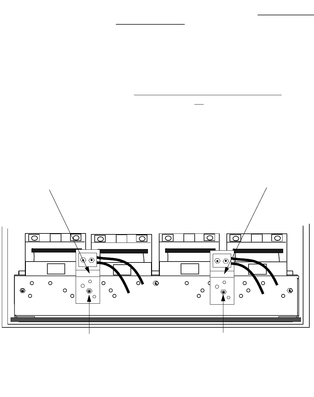
Component installation in the Modular Cell 4.0B and the
WNG24-BC battery cabinets
5- 23
Lucent Technologies – Proprietary
See notice on first page
401-703-454
FOA Draft Issue 1
January, 2006
............................................................................................................................................................................................................................................................
Attach the two battery
cable assemblies to the
retaining bracket (L1,L2,
and 12IR125 batteries only)
Important! This procedure, and the illustrations it contains,
uses 12IR125 batteries as an example. Refer to Examples of L1 and
L2 battery shelf positions on Page 5 - 24 for examples of L1 and L2
battery shelf positions.
Perform the following steps to attach the battery cable assemblies to the
retaining bracket (for L1, L2, and 12IR125 batteries only).
................................................................................................................................
............................................
1Attach the battery cable assemblies to the threaded rods that are
positioned between the left and right pair (string) of batteries, using the
nuts and washers provided. Do not connect the cables to the batteries at
this time. Refer to the figure below.
................................................................................................................................
............................................
2Repeat the previous step for all populated shelves.
LEFT BATTERY
STRING CABLE
BRACKET AND
CONNECTOR
RETAINING BRACKET
THREADED ROD
BETWEEN RIGHT
BATTERY STRING
PAIR
THREADED ROD
BETWEEN LEFT
BATTERY STRING-
PAIR
RIGHT BATTERY
STRING CABLE
BRACKET AND
CONNECTOR
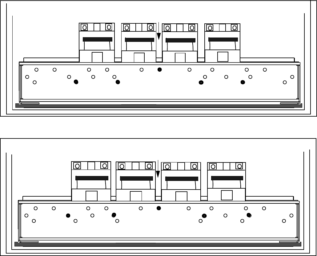
5-24 Lucent Technologies – Proprietary
See notice on first page 401-703-454
FOA Draft Issue 1
January, 2006
...........................................................................................................................................................................................................................................................
Component installation in the Modular Cell 4.0B and the
WNG24-BC battery cabinets
Examples of L1 and L2
battery shelf positions Refer to the three figures below for examples of L1 and L2 battery
shelf positions.
CENTER
THREADED HOLE
L1
BOTTOM ROW HOLES
CENTER
THREADED HOLE
L1
MIDDLE ROW HOLES
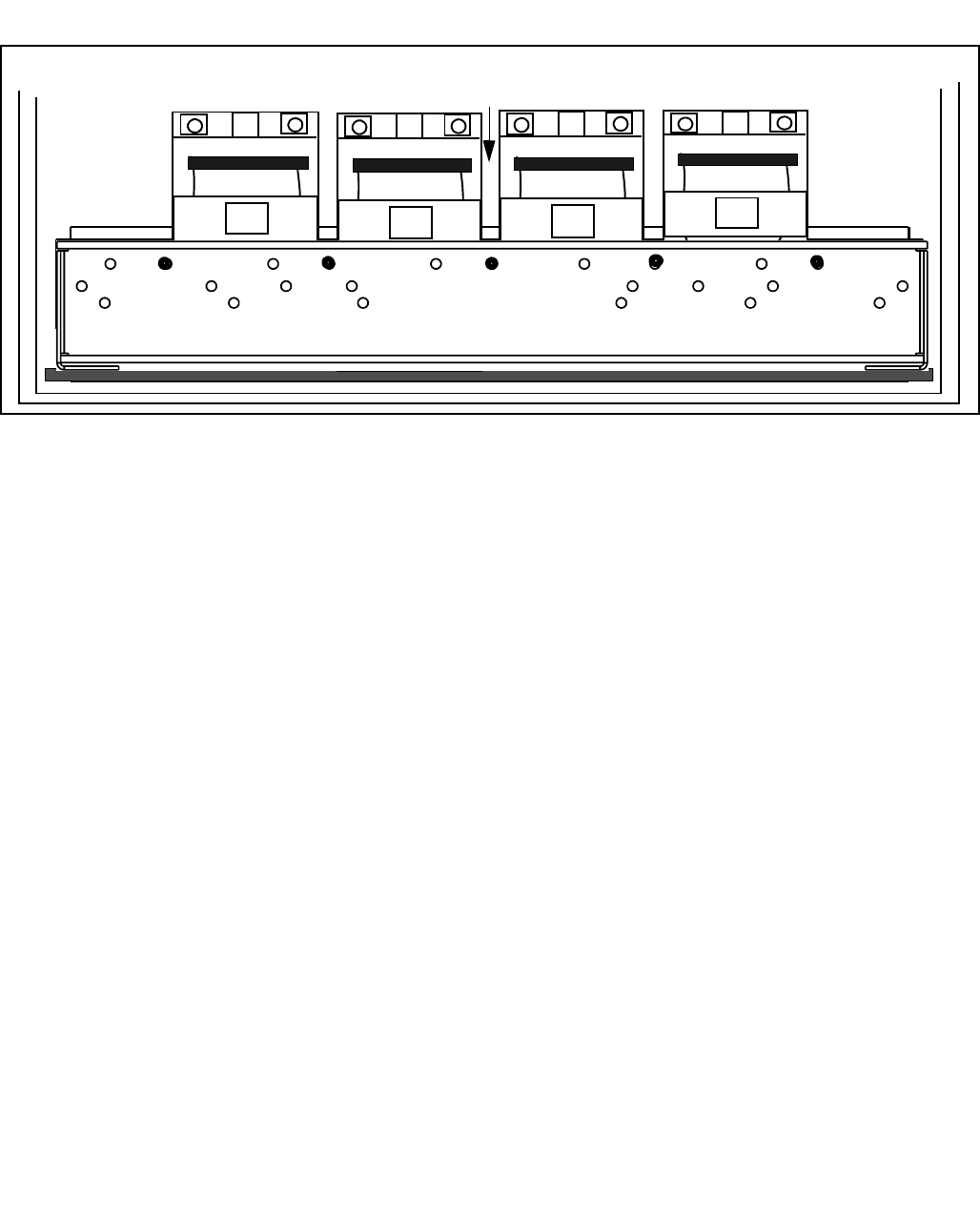
Component installation in the Modular Cell 4.0B and the
WNG24-BC battery cabinets
5- 25
Lucent Technologies – Proprietary
See notice on first page
401-703-454
FOA Draft Issue 1
January, 2006
............................................................................................................................................................................................................................................................
CENTER
THREADED HOLE
L2
TOP ROW HOLES

5-26 Lucent Technologies – Proprietary
See notice on first page 401-703-454
FOA Draft Issue 1
January, 2006
...........................................................................................................................................................................................................................................................
Component installation in the Modular Cell 4.0B and the
WNG24-BC battery cabinets
Connect positive battery
cables to all battery strings Important! When performing the following steps, do not
connect the negative battery cables. The negative battery cables
are not connected until after the interconnecting bus bars have
been installed in the next procedure.
Perform the following steps to connect the positive battery cables to all
battery strings.
................................................................................................................................
............................................
1Locate the ten battery cable assemblies. Refer to the figure below.
................................................................................................................................
............................................
2Starting with string 2 on the right side of shelf 1, remove the protective
cap (if present) from the terminals of battery 2. Refer to the figure below.
................................................................................................................................
............................................
3Apply antioxidant compound to the positive (+) terminal of battery 2 of
string 2.
+
-
STRING 2
BATTERY CABLE
ASSEMBLIES
(2 of 10)
+
-
12
(-) BLACK RED (+)
+
-
STRING 1
+
-
12
(-) BLACK RED (+)

Component installation in the Modular Cell 4.0B and the
WNG24-BC battery cabinets
5- 27
Lucent Technologies – Proprietary
See notice on first page
401-703-454
FOA Draft Issue 1
January, 2006
............................................................................................................................................................................................................................................................
................................................................................................................................
............................................
4Connect the positive (+) battery cable to the positive (+) terminal on
battery 2 of string 2, using either:
• a flat washer, lock washer and nut, or
• a flat washer, lock washer and bolt, if applicable
Refer to the figure on Page 5-29 for a top view of a typical battery
cable connection.
................................................................................................................................
............................................
5Torque the positive battery connections using an insulated socket and
torque wrench set at 60 in.-lb. (6.8 Nm). Do not use the torque
specifications provided in Chapter 1.
................................................................................................................................
............................................
6Repeat Steps 1 through 5 for the number 2 battery in all remaining
END OF STEPS
................................................................................................................................
.............................................
battery strings.
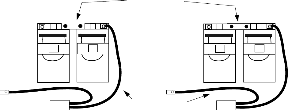
5-28 Lucent Technologies – Proprietary
See notice on first page 401-703-454
FOA Draft Issue 1
January, 2006
...........................................................................................................................................................................................................................................................
Component installation in the Modular Cell 4.0B and the
WNG24-BC battery cabinets
Attach interconnecting bus
bars to all battery strings Perform the following steps to attach interconnecting bus bars to all
battery strings.
................................................................................................................................
............................................
1Starting with string 2 on the right side of shelf 1, remove the protective
cap (if present) from the terminals of battery 1.
................................................................................................................................
............................................
2Remove the interconnecting bus bar from the kit that is provided with
each pair of batteries.
................................................................................................................................
............................................
3Polish the interconnecting bus bar.
................................................................................................................................
............................................
4Apply antioxidant compound to the interconnecting bus bar.
................................................................................................................................
............................................
5Apply antioxidant compound to the positive (+) terminal of battery 1
and the negative (-) terminal of battery 2 of string 2.
................................................................................................................................
............................................
6On string 2, place an interconnecting bus bar between the positive
terminal of the left-hand battery (#1) and the negative terminal of the
right-hand battery (#2). Refer to the figure below.
+
-
STRING 2
BATTERY CABLE
ASSEMBLIES
(2 of 10)
+
-
12
(-) BLACK RED (+)
+
-
STRING 1
+
-
12
(-) BLACK RED (+)
BATTERY STRING
BUS BARS
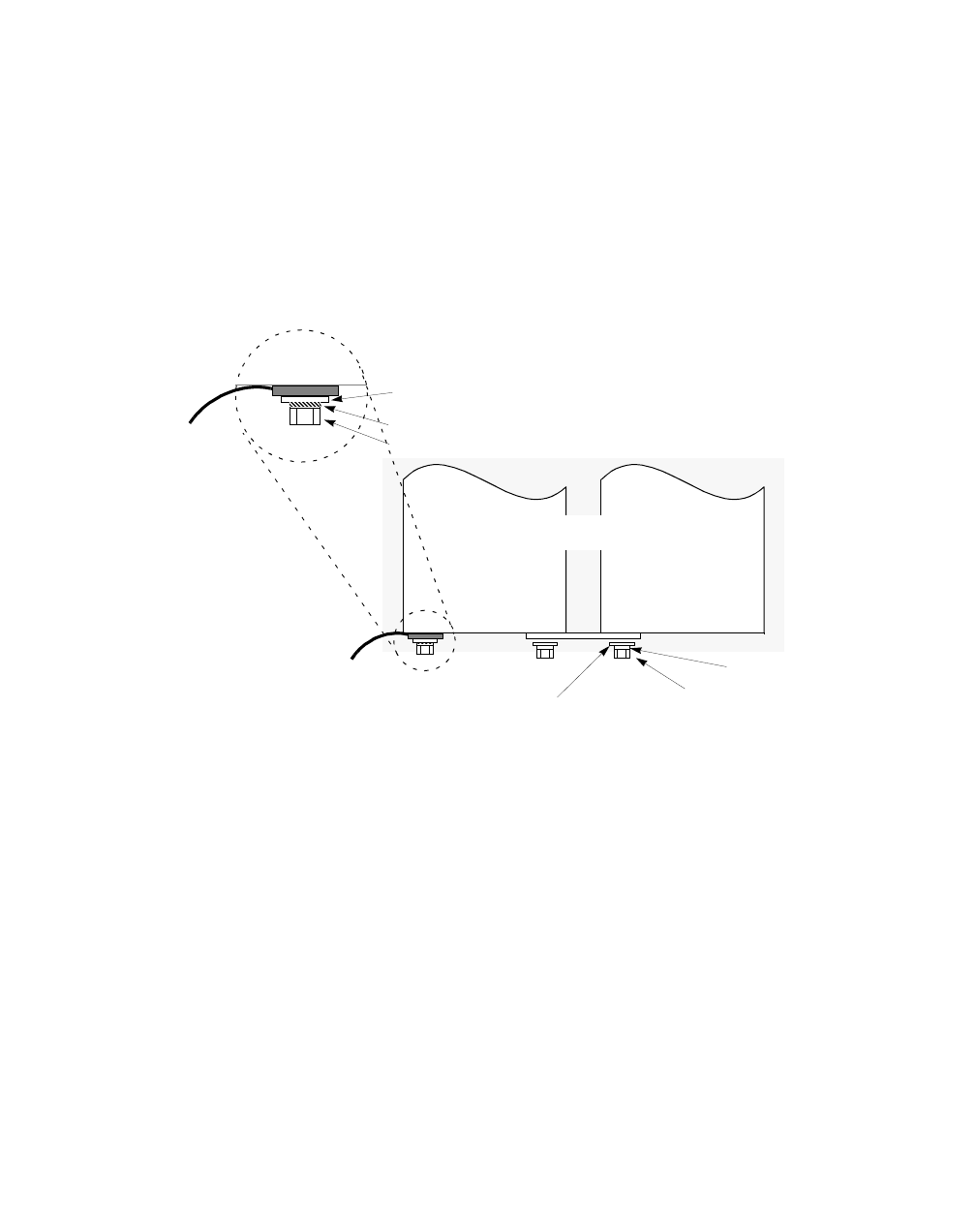
Component installation in the Modular Cell 4.0B and the
WNG24-BC battery cabinets
5- 29
Lucent Technologies – Proprietary
See notice on first page
401-703-454
FOA Draft Issue 1
January, 2006
............................................................................................................................................................................................................................................................
................................................................................................................................
............................................
7Connect the interconnecting bus bar using either:
• a flat washer, lock washer and nut, or
• a flat washer, lock washer and bolt, if applicable
Refer to the figure below, which illustrates the interconnecting bus
bar installation, including the installation order of the washers.
................................................................................................................................
............................................
8Torque the two bus bar connections using an insulated socket and torque
wrench set at 60 in.-lb. (6.8 Nm). Do not use the torque specifications
provided in Chapter 1.
................................................................................................................................
............................................
END OF STEPS
................................................................................................................................
.............................................
9Repeat Steps 1 through 8 for the remaining battery strings.
-
+
LOCK WASHER
BATTERY
CABLE
BATTERY
CABLE
BATTERY 2
BATTERY 1
LOCK WASHER
FLAT WASHER NUT OR BOLT
TOP VIEW
NUT OR BOLT
FLAT WASHER
5-30 Lucent Technologies – Proprietary
See notice on first page 401-703-454
FOA Draft Issue 1
January, 2006
...........................................................................................................................................................................................................................................................
Component installation in the Modular Cell 4.0B and the
WNG24-BC battery cabinets
Connect the negative
battery cables to all battery
strings
Perform the following steps to connect the negative battery cables to all
battery strings. Refer to the figure below.
................................................................................................................................
............................................
1Apply antioxidant compound to the negative (-) terminal of battery 1 of
string 2.
................................................................................................................................
............................................
2Place the negative (-) battery cable on the negative (-) terminal on
battery 1, string 2, using either:
• a flat washer, lock washer and nut, or
• a flat washer, lock washer and bolt, if applicable
Refer to the figure on Page 5-29 for a top view of a typical battery
cable connection. Refer to the figure on Page 5-31 for negative
battery cable connections.
................................................................................................................................
............................................
3 Repeat Steps 1 and 2 for all remaining battery strings.
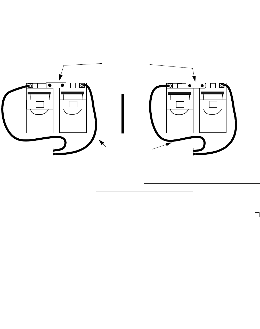
Component installation in the Modular Cell 4.0B and the
WNG24-BC battery cabinets
5- 31
Lucent Technologies – Proprietary
See notice on first page
401-703-454
FOA Draft Issue 1
January, 2006
............................................................................................................................................................................................................................................................
................................................................................................................................
............................................
4Torque the negative battery connections using an insulated socket and
torque wrench set at 60 in.-lb. (6.8 Nm). Do not use the torque
specifications provided in Chapter 1.
Important!Skip to How to route the thermal probe cable(s) and mount
the thermal probe(s) in the battery cabinets on Page 5 - 81 to continue
E
ND OF STEPS
....
.........................................................................................................
..................................................................
the installation.
+
-
STRING 2
BATTERY CABLE
ASSEMBLIES
(2 of 10)
+
-
12
(-) BLACK
RED (+)
+
-
STRING 1
+
-
12
(-) BLACK
RED (+)
BATTERY STRING
BUS BARS

5-32 Lucent Technologies – Proprietary
See notice on first page 401-703-454
FOA Draft Issue 1
January, 2006
...........................................................................................................................................................................................................................................................
Component installation in the Modular Cell 4.0B and the
WNG24-BC battery cabinets
.............................................................................................................................................................................................................................................................
How to install C-11 batteries on type 1 battery shelves
Overview This section provides instructions for the installation and connection of
C-11 batteries on type 1 battery shelves. The instructions are the same
for both a first or second battery cabinet (that have type 1 shelves),
except in the case of thermal probes, where the exceptions are noted.
This section contains the following procedures.
Read battery installation
procedure overview Important! In the event that the battery compartment is
removed from the primary cabinet because of an upgrade that adds
the A6 amplifier shelf (carriers 5 and 6), up to four spare L1
batteries will result. The end user may wish to use these batteries
in the battery cabinet, in which case a shelf must be left vacant.
Therefore, while performing any task involving a type 1 top
battery shelf (shelf 5), it may be desirable to plan on leaving that
shelf empty when installing the batteries.
The battery cabinet can contain up to thirty C-11 batteries that are
wired in a series/parallel configuration which provides 24-volt backup.
For C-11 batteries, one string (six batteries) can be mounted on each of
the five type 1 battery shelves. Refer to the figure on Page 5-34.
Prepare the batteries for
installation To prepare the batteries, follow all appropriate standard practices for
the storage and handling of batteries. Complete the warranty
procedures and the following steps.
Place the C-11 batteries on a shelf 5 - 35
Install the battery retaining bracket 5 - 37
Attach the two battery cable assemblies to the retaining
bracket (C-11 batteries only)
5 - 39
Place the battery negative and positive bus bars 5 - 40
Connect the positive battery cables to the batteries 5 - 42
Attach the interconnecting bus bars 5 - 44
Connect the negative battery cables to the batteries 5 - 46
Install the insulating battery terminal covers 5 - 48
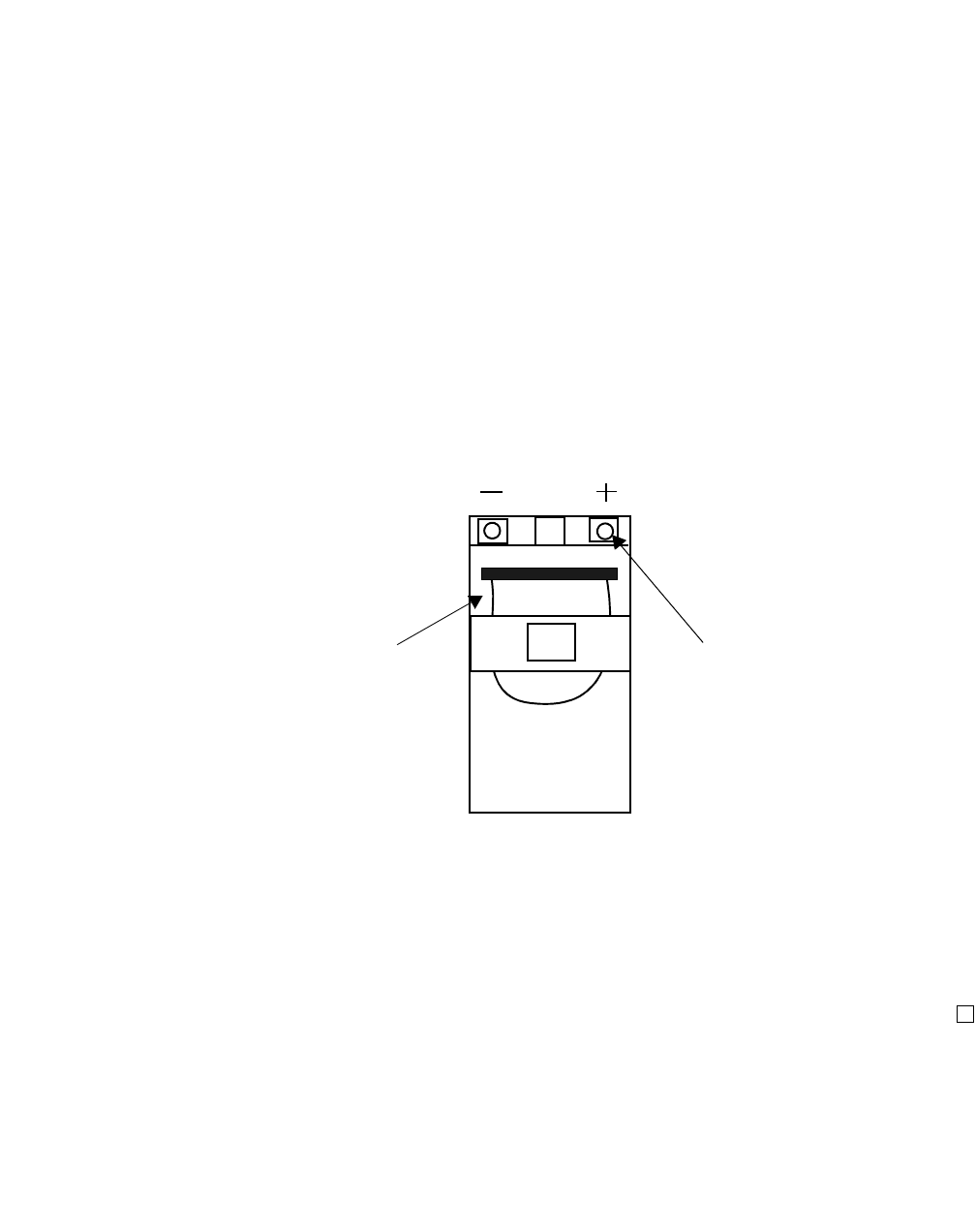
Component installation in the Modular Cell 4.0B and the
WNG24-BC battery cabinets
5- 33
Lucent Technologies – Proprietary
See notice on first page
401-703-454
FOA Draft Issue 1
January, 2006
............................................................................................................................................................................................................................................................
................................................................................................................................
............................................
1Check and record battery initial voltages and all battery date codes.
................................................................................................................................
............................................
2Include this information with documentation supplied to the customer.
END OF STEPS
................................................................................................................................
.............................................
Description of the batteries
The battery terminals are located on one end of the battery. Positive and
negative terminals are clearly labeled “+” and “-”. Strap handles are
permanently attached to the battery. Refer to the example figure below.
Important! To prevent an inadvertent electrical short during
battery installation, the C-11 batteries have an insulated cover that
is factory-installed over the terminals on the individual batteries.
Do not remove this cover until you are preparing to complete each
connection.
BATTERY
STRAP
TERMINAL
FOR
BATTERY
CABLE
ATTACHMENT
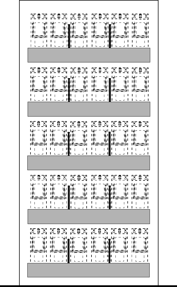
5-34 Lucent Technologies – Proprietary
See notice on first page 401-703-454
FOA Draft Issue 1
January, 2006
...........................................................................................................................................................................................................................................................
Component installation in the Modular Cell 4.0B and the
WNG24-BC battery cabinets
The figure below illustrates the battery string positions and battery
numbers for C-11 batteries on type 1 shelves.
STRING 5
STRING 4
STRING 3
STRING 2
STRING 1
123456
123456
123456
123456
123456
FRONT VIEW
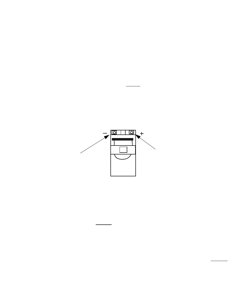
Component installation in the Modular Cell 4.0B and the
WNG24-BC battery cabinets
5- 35
Lucent Technologies – Proprietary
See notice on first page
401-703-454
FOA Draft Issue 1
January, 2006
............................................................................................................................................................................................................................................................
Place the C-11 batteries on
a shelf Use the following procedure to place batteries on a shelf, starting with
shelf 1 (bottom).
Important! This procedure, and the illustrations it contains, are
generic in nature, in order that they may be used for all battery
types.
................................................................................................................................
............................................
1Locate the 25 threaded rods shipped with the cabinet.
................................................................................................................................
............................................
2Thread a rod into the center hole of the rear bracket as shown in the Step
8 figure on Page 5- 36, item 1.
................................................................................................................................
............................................
3Slide two batteries onto the shelf, one on each side of the center threaded
rod. Refer to the figure on Page 5-36, item 2.
Important! When installed, the battery terminals on the front,
narrow end of the battery should face out of the cabinet. Refer to
the figure below.
................................................................................................................................
............................................
4Place a spacer (supplied with the batteries) on the outside of the two
batteries installed in the previous step. Refer to the figure on Page 5-36,
item 3.
................................................................................................................................
............................................
5Slide two batteries onto the shelf, one on each side of the spacers
installed in the previous step. Refer to the figure on Page 5-36, item 4.
................................................................................................................................
............................................
6Thread a rod into the appropriate hole on the outside of the two batteries
installed in the previous step. Refer to the figure below, item 5.
POSITIVE
BATTERY
TERMINAL
(-) BLACK RED (+)
NEGATIVE
BATTERY
TERMINAL
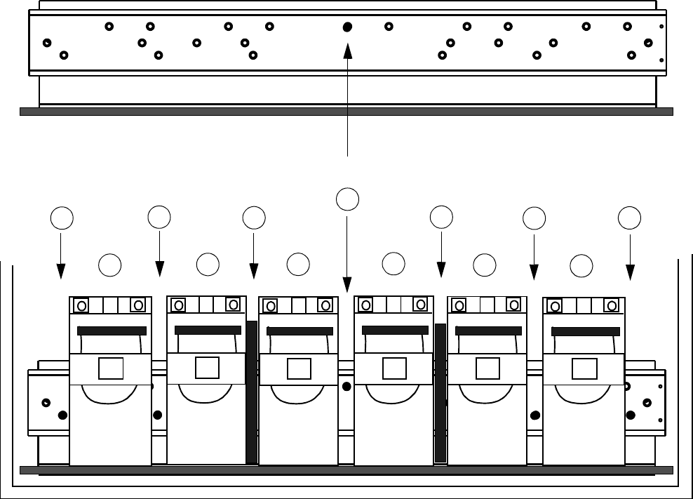
5-36 Lucent Technologies – Proprietary
See notice on first page 401-703-454
FOA Draft Issue 1
January, 2006
...........................................................................................................................................................................................................................................................
Component installation in the Modular Cell 4.0B and the
WNG24-BC battery cabinets
................................................................................................................................
............................................
7Slide the last two C-11 batteries onto the shelf on each side of the
threaded rods installed in the previous step. Refer to the figure below,
item 6.
................................................................................................................................
............................................
8Thread a rod into the appropriate hole on the outside of the last two
batteries installed in the previous step. Refer to the figure below, item 7.
................................................................................................................................
............................................
9Repeat Steps 1 through 8 for all battery shelves to be populated.
Important! In the event of an upgrade of the primary cabinet
that adds the A6 amplifier shelf, the battery compartment is
removed. This results in four spare L1 batteries.
2
CENTER THREADED HOLE
REAR SHELF BRACKET
2
3
3
4
4
55
66
77
1
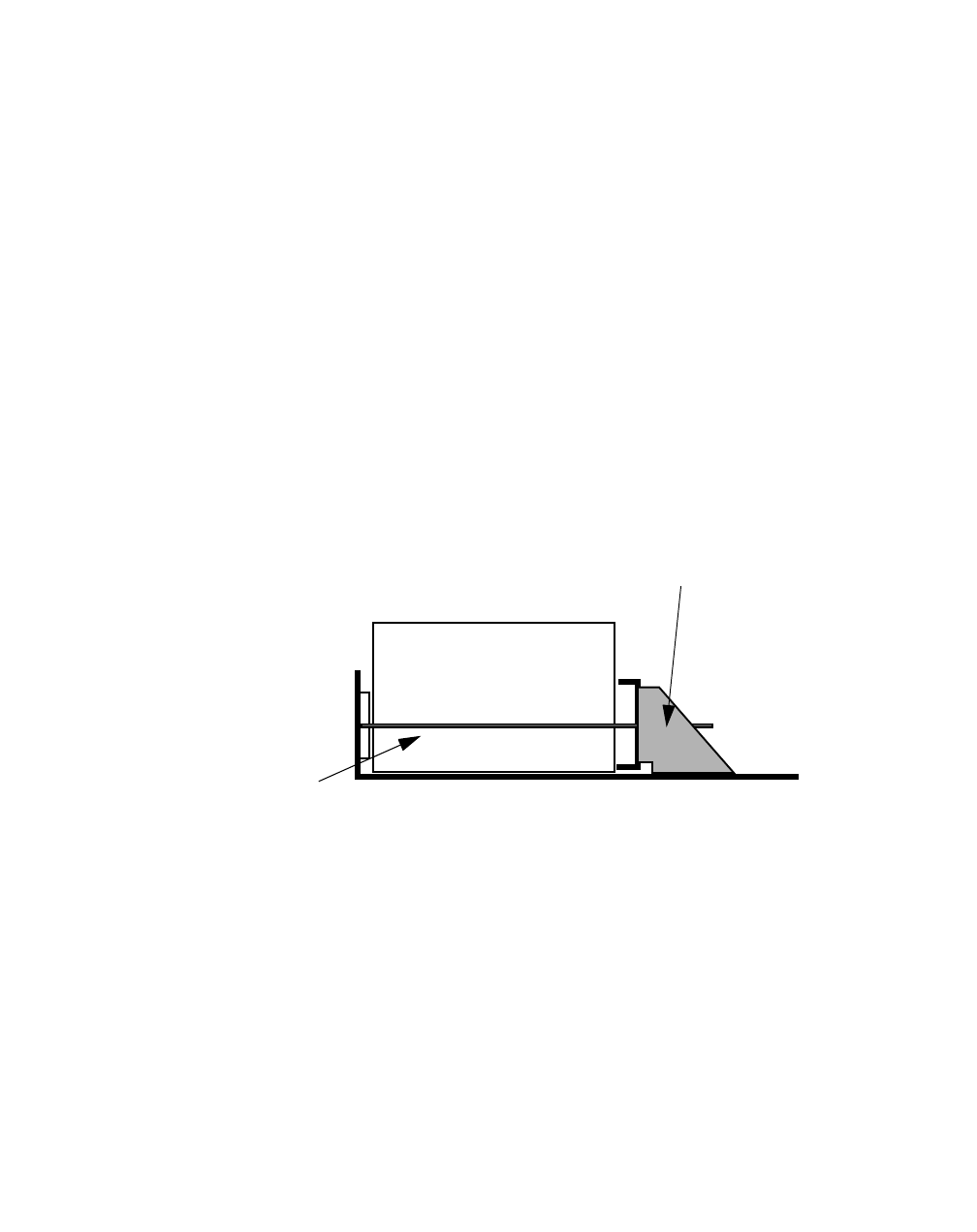
Component installation in the Modular Cell 4.0B and the
WNG24-BC battery cabinets
5- 37
Lucent Technologies – Proprietary
See notice on first page
401-703-454
FOA Draft Issue 1
January, 2006
............................................................................................................................................................................................................................................................
Therefore, it may be desirable to plan on leaving the top shelf
empty when installing the batteries.
................................................................................................................................
............................................
10 Carefully wrap and store the remaining threaded rods, retaining bracket
and associated hardware on all shelves not being populated with
batteries at this time.
Install the battery retaining
bracket Perform the following steps to install the battery retaining bracket.
................................................................................................................................
............................................
1Preposition the retaining bracket in the position shown below for C-11
batteries.
Important! When performing the next steps, note that the figure
illustrates an example only.
................................................................................................................................
............................................
2Slide the retaining bracket over the installed threaded rods.
LEFT SIDE VIEW
C-11 BATTERIES
RETAINING
BRACKET
POSITION 2
THREADED ROD
(1 of 5 per shelf)
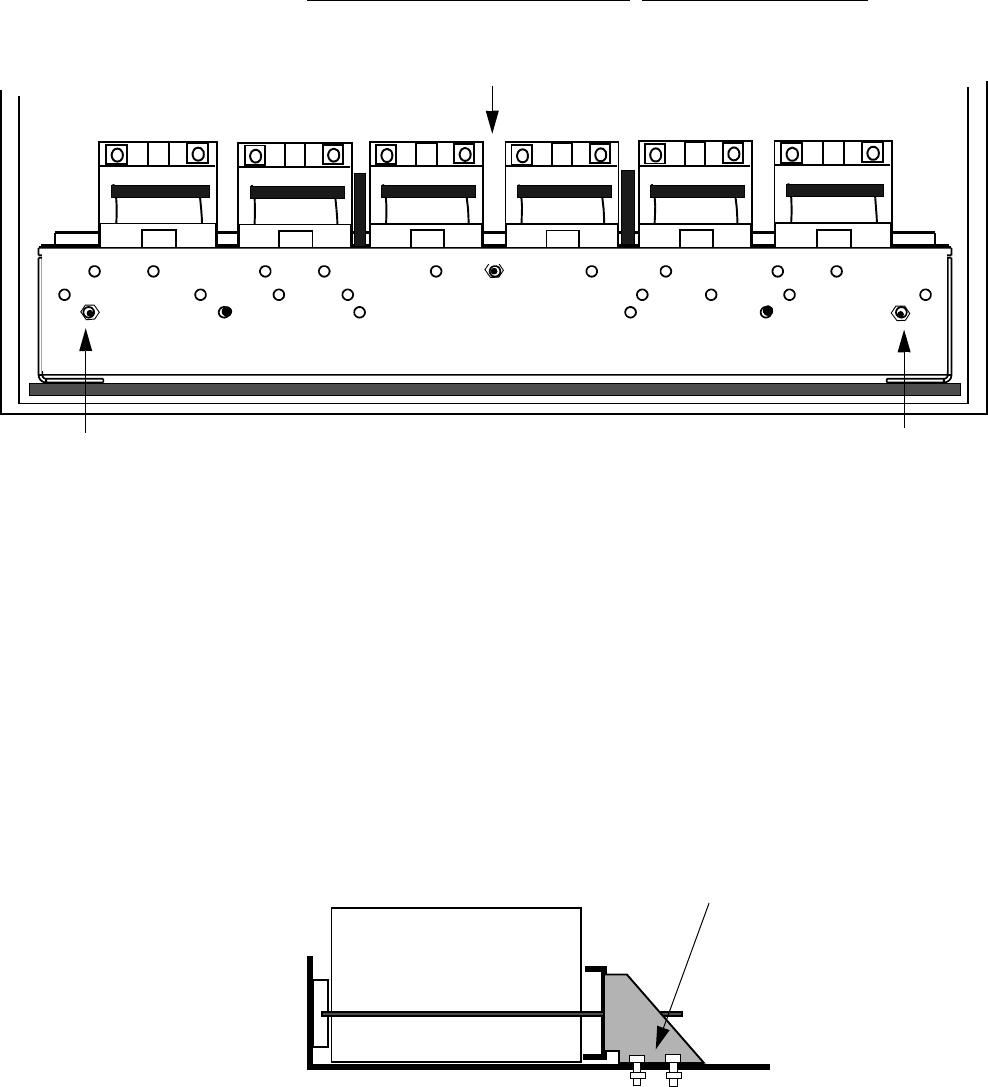
5-38 Lucent Technologies – Proprietary
See notice on first page 401-703-454
FOA Draft Issue 1
January, 2006
...........................................................................................................................................................................................................................................................
Component installation in the Modular Cell 4.0B and the
WNG24-BC battery cabinets
................................................................................................................................
............................................
3Using the nuts and washers provided, attach the retaining bracket at the
center and end threaded rods only. Do not tighten the nuts.
................................................................................................................................
............................................
4Using the supplied bolts, washers and nuts, attach the retaining bracket
to the shelf. Four sets of hardware are used, two on each side of the
bracket. Refer to the figure below.
................................................................................................................................
............................................
5Repeat Steps 1 through 4 for all populated battery shelves.
CENTER
THREADED ROD
END THREADED ROD
END THREADED ROD
RETAINING BRACKET
LEFT SIDE VIEW
RETAINING
BRACKET
POSITION FOR C-11
BATTERIES
BOLTS AND NUTS FOR
RETAINING BRACKETS
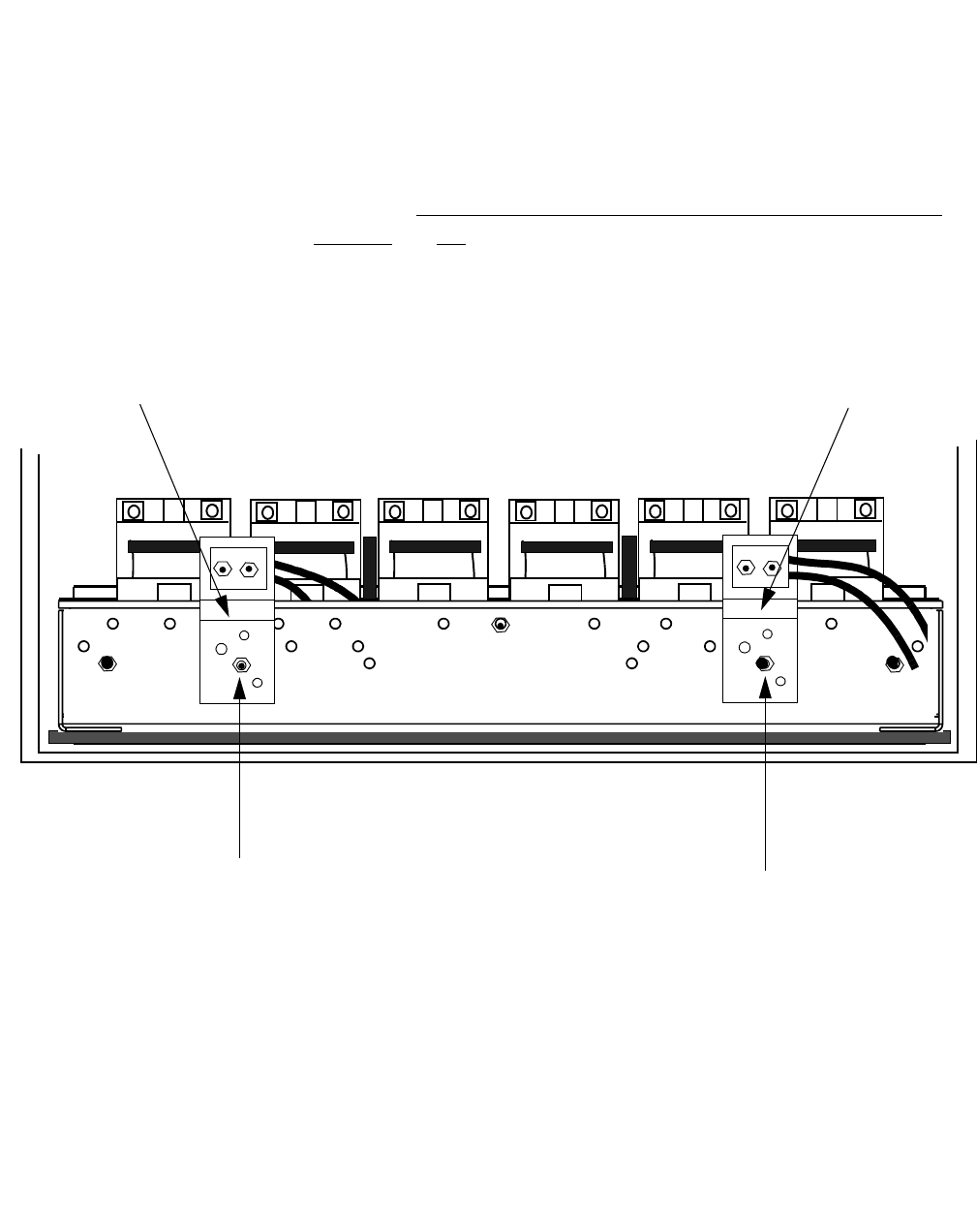
Component installation in the Modular Cell 4.0B and the
WNG24-BC battery cabinets
5- 39
Lucent Technologies – Proprietary
See notice on first page
401-703-454
FOA Draft Issue 1
January, 2006
............................................................................................................................................................................................................................................................
Attach the two battery
cable assemblies to the
retaining bracket (C-11
batteries only)
Perform the following steps to attach the battery cable assemblies to the
retaining bracket (for C-11 batteries only).
................................................................................................................................
............................................
1Attach the battery cable assemblies to the threaded rods that are
positioned between the left two batteries and between the right two
batteries. Do not connect the cables to the batteries at this time. Refer to
the figure below.
................................................................................................................................
............................................
END OF STEPS
................................................................................................................................
.............................................
2Tighten all five nuts.
LEFT BATTERY
CABLE BRACKET
AND CONNECTOR
RIGHT BATTERY
CABLE BRACKET
AND CONNECTOR
THREADED ROD
BETWEEN LEFT
TWO BATTERIES
THREADED ROD
BETWEEN RIGHT
TWO BATTERIES
+_
+_
_

5-40 Lucent Technologies – Proprietary
See notice on first page 401-703-454
FOA Draft Issue 1
January, 2006
...........................................................................................................................................................................................................................................................
Component installation in the Modular Cell 4.0B and the
WNG24-BC battery cabinets
Place the battery negative
and positive bus bars Important! Although all four parallel bus bars are identical,
observe that the orientation of the positive and negative parallel
bus bars is different on the left three batteries (1, 2 and 3) than on
the right three batteries (4, 5 and 6). Also observe that the negative
and positive pairs are positioned in a reverse orientation to each
other. Refer to the figure on Page 5-41.
Refer to the figure on Page 5-41, and perform the following steps to
connect the negative and positive bus bars.
................................................................................................................................
............................................
1Apply antioxidant compound to the positive (+) terminal and
negative (-) terminal of all batteries.
Important! When performing the next two steps, refer to the
Step 5 figure on Page 5- 41. For batteries 1, 2, and 3, use "A" for
positive bus bar installation and "B" for negative bus bar
installation. For batteries 4, 5, and 6, use "C" for negative bus bar
installation and "D" for positive bus bar installation.
................................................................................................................................
............................................
2Place bus bars on batteries 1, 2, and 3.
• Place a bus bar (A) on the positive terminals with the bend facing
toward the batteries.
• Place a bus bar (B) on the negative terminals with the bend facing
away from the batteries.
................................................................................................................................
............................................
3Place bus bars on batteries 4, 5, and 6.
• Place a bus bar (C) on the negative terminals with the bend facing
toward the batteries.
• Place a bus bar (D) on the positive terminals with the bend facing
away from the batteries.
................................................................................................................................
............................................
4Temporarily secure each bus bar in place with a washer and nut.
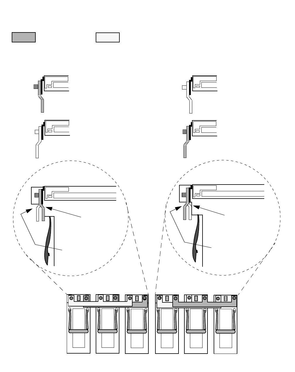
Component installation in the Modular Cell 4.0B and the
WNG24-BC battery cabinets
5- 41
Lucent Technologies – Proprietary
See notice on first page
401-703-454
FOA Draft Issue 1
January, 2006
............................................................................................................................................................................................................................................................
................................................................................................................................
............................................
5Repeat Steps 1 through 4 for all remaining battery shelves, if applicable.
Refer to the figure below.
12
3456
+
_
+
+
+
+
+
_
_
_
_
_
_
+
_
+
_
+
POSITIVE
BEND FACING
TOWARD BAT-
TERIES (A)
POSITIVE BEND
FACING AWAY
FROM BATTERIES
(D)
NEGATIVE
BEND FACING
TOWARD BAT-
TERIES (C)
NEGATIVE
BEND FACING
AWAY FROM
BATTERIES (B)
_
+
+
_
A
B
C
D
A + B C + D
=
=
A
BCD
LEFT: BATTERIES 1, 2, 3
RIGHT SIDE VIEW RIGHT: BATTERIES 4, 5, 6
RIGHT SIDE VIEW
FRONT VIEW FRONT VIEW
5-42 Lucent Technologies – Proprietary
See notice on first page 401-703-454
FOA Draft Issue 1
January, 2006
...........................................................................................................................................................................................................................................................
Component installation in the Modular Cell 4.0B and the
WNG24-BC battery cabinets
Connect the positive
battery cables to the
batteries
Important! When performing the following steps, for safety
reasons, always connect the positive battery cables first and the
negative battery cables last (when instructed to do so).
Perform the following steps to connect the positive battery cables to the
batteries.
................................................................................................................................
............................................
1Locate the previously mounted battery cable assemblies on the bottom
shelf.
................................................................................................................................
............................................
2Separate two of the battery cables. The positive cables from each of the
two battery cable assemblies will be connected to the batteries in the
next step.
Important! When performing the next step, note that the two
positive battery cables being connected come from two separate
battery connectors. Refer to the figure on Page 5-43.
................................................................................................................................
............................................
3Apply antioxidant compound to the two positive (+) terminals of
batteries 5 and 6. Refer to the figure on Page 5-43.
................................................................................................................................
............................................
4Connect the two positive (+) battery cables (from separate connectors)
to the positive (+) terminals of batteries 5 and 6, using the flat washers,
lock washers and nuts.
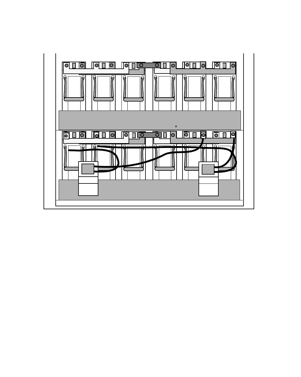
Component installation in the Modular Cell 4.0B and the
WNG24-BC battery cabinets
5- 43
Lucent Technologies – Proprietary
See notice on first page
401-703-454
FOA Draft Issue 1
January, 2006
............................................................................................................................................................................................................................................................
................................................................................................................................
..............................................
5Repeat Steps 2 through 4 for all populated battery shelves. Remember,
for safety reasons, to connect the positive battery cables first and the
negative battery cables last (when instructed to do so).
................................................................................................................................
..............................................
6Do not torque the nuts on the positive battery connections at this time.
The nuts on all positive battery connections will be torqued after
END OF STEPS
................................................................................................................................
...............................................
mounting of the series bus bars in the next procedure.
S-1
S-2
123456
123456
++
_
+
_
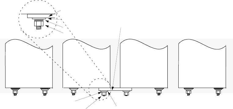
5-44 Lucent Technologies – Proprietary
See notice on first page 401-703-454
FOA Draft Issue 1
January, 2006
...........................................................................................................................................................................................................................................................
Component installation in the Modular Cell 4.0B and the
WNG24-BC battery cabinets
Attach the interconnecting
bus bars Perform the following steps to connect the interconnecting bus bars. Do
the bottom shelf first.
................................................................................................................................
............................................
1Remove the series bus bar from the kit provided with the batteries.
................................................................................................................................
............................................
2Apply antioxidant compound to the interconnecting bus bar, the positive
(+) terminal of battery 3, and the negative (-) terminal of battery 4. Refer
to the figure below.
................................................................................................................................
............................................
3Place the interconnecting bus bar between the positive terminal of
battery 3 and the negative terminal of battery 4.
................................................................................................................................
............................................
4Connect the interconnecting bus bar using the flat washers, lock washers
and nuts. Refer to the figure below for a top view (for mounting order).
Refer to the figure on Page 5-45 for a front view.
++
+
_
PARALLEL BUS BARS AND CABLES NOT SHOWN FOR CLARITY
FLAT WASHER
FLAT WASHER
LOCK WASHER
LOCK WASHER
NUT
NUT
BATTERY 4
BATTERY 3
BATTERY 2
TOP VIEW
SERIES BUS BAR
SERIES BUS BAR
+
_
BATTERY 5
__
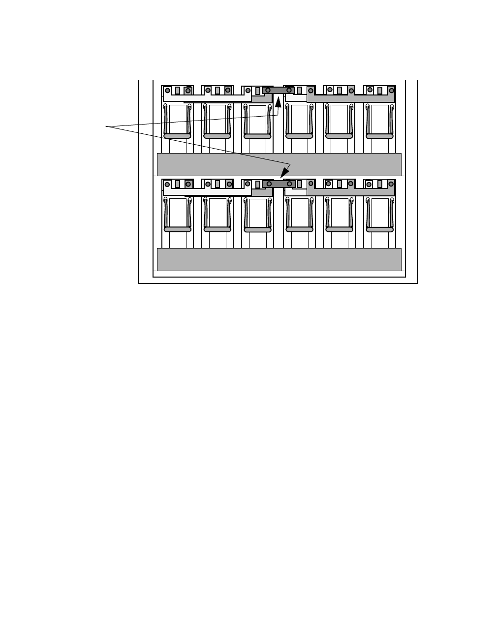
Component installation in the Modular Cell 4.0B and the
WNG24-BC battery cabinets
5- 45
Lucent Technologies – Proprietary
See notice on first page
401-703-454
FOA Draft Issue 1
January, 2006
............................................................................................................................................................................................................................................................
................................................................................................................................
............................................
5Repeat Steps 1 through 4 for the remaining battery shelves, if applicable.
Refer to the figure below.
................................................................................................................................
............................................
6Torque the following connections using an insulated 10-mm socket and
torque wrench set at 62 in.-lb. (7.0 Nm). Do not use the torque
specifications provided in Chapter 1.
• All series bus bar connections (+ and -, all shelves)
• All remaining positive battery connections, all shelves
• Negative battery connections on batteries 5 and 6, all shelves
123456
123456
S1
S2
SERIES
BUS BARS
BATTERY CABLES NOT SHOWN FOR CLARITY
5-46 Lucent Technologies – Proprietary
See notice on first page 401-703-454
FOA Draft Issue 1
January, 2006
...........................................................................................................................................................................................................................................................
Component installation in the Modular Cell 4.0B and the
WNG24-BC battery cabinets
Connect the negative
battery cables to the
batteries
Perform the following steps to connect the negative battery cables to
the batteries.
................................................................................................................................
............................................
1Separate two of the battery cables. The negative cables from each of the
two battery cables will be connected to the batteries in the next step.
Important! When performing the next step, note that the two
negative battery cables being connected come from two separate
battery connectors. Refer to the figure on Page 5-47.
................................................................................................................................
............................................
2Apply antioxidant compound to the two negative (-) battery terminals of
batteries 1 and 2. Refer to the figure on Page 5-47.
................................................................................................................................
............................................
3Connect the two negative (-) battery cables (from separate connectors)
to the negative (-) terminal of batteries 1 and 2, using the flat washers,
lock washers and nuts. Refer to the figure on Page 5-47.
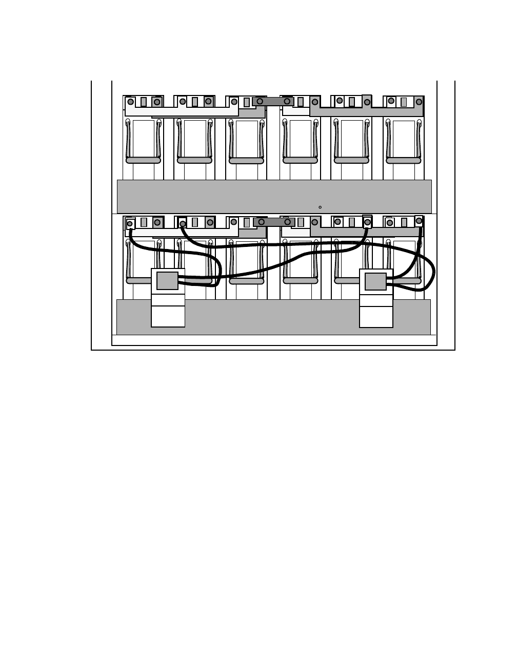
Component installation in the Modular Cell 4.0B and the
WNG24-BC battery cabinets
5- 47
Lucent Technologies – Proprietary
See notice on first page
401-703-454
FOA Draft Issue 1
January, 2006
............................................................................................................................................................................................................................................................
................................................................................................................................
............................................
4Repeat Steps 2 and 3 for all remaining battery shelves, if applicable.
................................................................................................................................
............................................
5Torque all remaining negative connections using an insulated 7/16-inch
socket and torque wrench set at 62 in.-lb. (7.0 Nm). Do not use the
END OF STEPS
................................................................................................................................
.............................................
torque specifications provided in Chapter 1.
S-1
S-2
123456
123456
+
+
_+
_
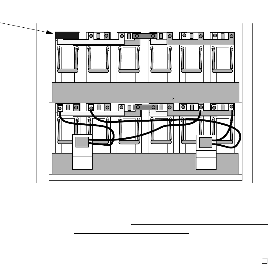
5-48 Lucent Technologies – Proprietary
See notice on first page 401-703-454
FOA Draft Issue 1
January, 2006
...........................................................................................................................................................................................................................................................
Component installation in the Modular Cell 4.0B and the
WNG24-BC battery cabinets
Install the insulating
battery terminal covers Perform the following steps to install the insulating battery terminal
covers.
................................................................................................................................
............................................
1Place all insulating covers on the battery terminals, as shown in the
figure below.
Important!Skip to How to route the thermal probe cable(s) and mount
the thermal probe(s) in the battery cabinets on Page 5 - 81 to continue
E
ND OF STEPS
....
.........................................................................................................
..................................................................
the installation.
I
NSULATING
C
OVER
(
EXAMPLE:
1
per BATTERY)
S-1
S-2
123456
123456
+
+
_+
_

Component installation in the Modular Cell 4.0B and the
WNG24-BC battery cabinets
5- 49
Lucent Technologies – Proprietary
See notice on first page
401-703-454
FOA Draft Issue 1
January, 2006
............................................................................................................................................................................................................................................................
.............................................................................................................................................................................................................................................................
How to install 12IR125 type batteries on type 2 battery shelves
Overview This section provides instructions for the installation and connection of
12IR125 batteries. The instructions are the same for both a first or
second battery cabinet, except in the case of thermal probes, where the
exceptions are noted. This section contains the following procedures.
Read battery installation
procedure overview Important! In the event that the battery compartment is
removed from the primary cabinet because of an upgrade that adds
the A6 amplifier shelf (carriers 5 and 6), up to four spare L1
batteries will result. The end user may wish to use these batteries
in the battery cabinet, in which case a shelf must be left vacant.
Therefore, while performing any task involving a type 1 top
battery shelf (shelf 5), it may be desirable to plan on leaving that
shelf empty when installing the batteries.
The battery cabinet can contain up to 20 batteries that are wired in a
series/parallel configuration which provides 24-volt backup. Two
strings (four batteries) can be mounted on each shelf of the battery
cabinet. Refer to the figure on Page 5-51.
Prepare the 12IR125
batteries for installation To prepare the12IR125 batteries, follow all appropriate standard
practices for the storage and handling of batteries. Complete the
warranty procedures and the following steps.
................................................................................................................................
............................................
1Check and record battery initial voltages.
................................................................................................................................
............................................
2Record all battery date codes.
Place the 12IR125 batteries on a shelf 5 - 52
Adjust and secure the front battery retaining brackets 5 - 55
Connect positive battery cables to all battery strings 5 - 57
Attach interconnecting bus bars to all battery strings 5 - 59
Connect the negative battery cables to all battery strings 5 - 61
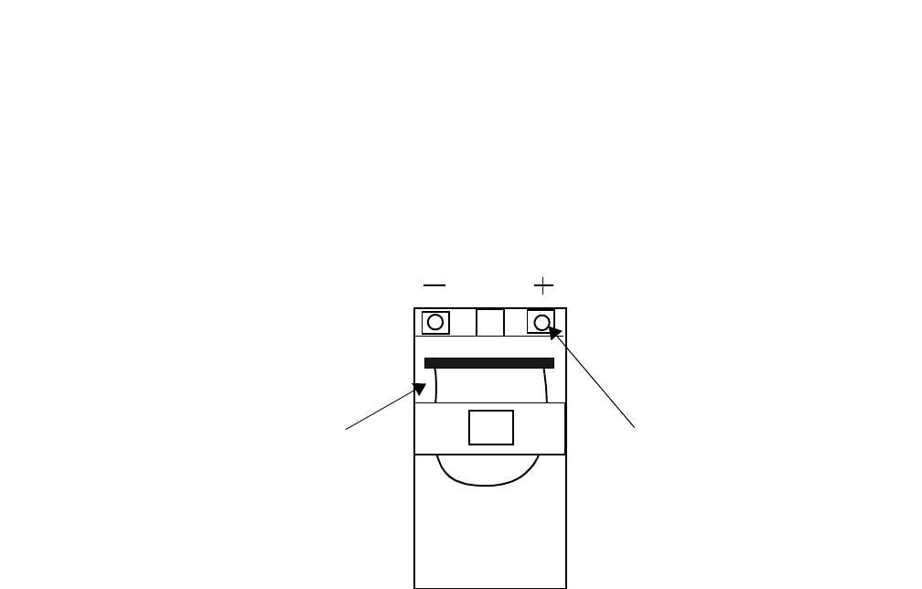
5-50 Lucent Technologies – Proprietary
See notice on first page 401-703-454
FOA Draft Issue 1
January, 2006
...........................................................................................................................................................................................................................................................
Component installation in the Modular Cell 4.0B and the
WNG24-BC battery cabinets
................................................................................................................................
............................................
3Include this information with documentation supplied to the customer.
END OF STEPS
................................................................................................................................
.............................................
Description of the batteries
The 12IR125 battery terminals are located on one end of the battery.
Positive and negative terminals are clearly labeled “+” and “-”. Strap
handles are permanently attached to the battery. Refer to the example
figure below.
Important! To prevent an inadvertent electrical short during
battery installation, certain battery types have an insulated cover
that is factory-installed over the terminals on the individual
batteries. Do not remove this cover until you are preparing to
complete each connection.
BATTERY
STRAP
NUT or BOLT
BATTERY
CABLE
ATTACHMENT
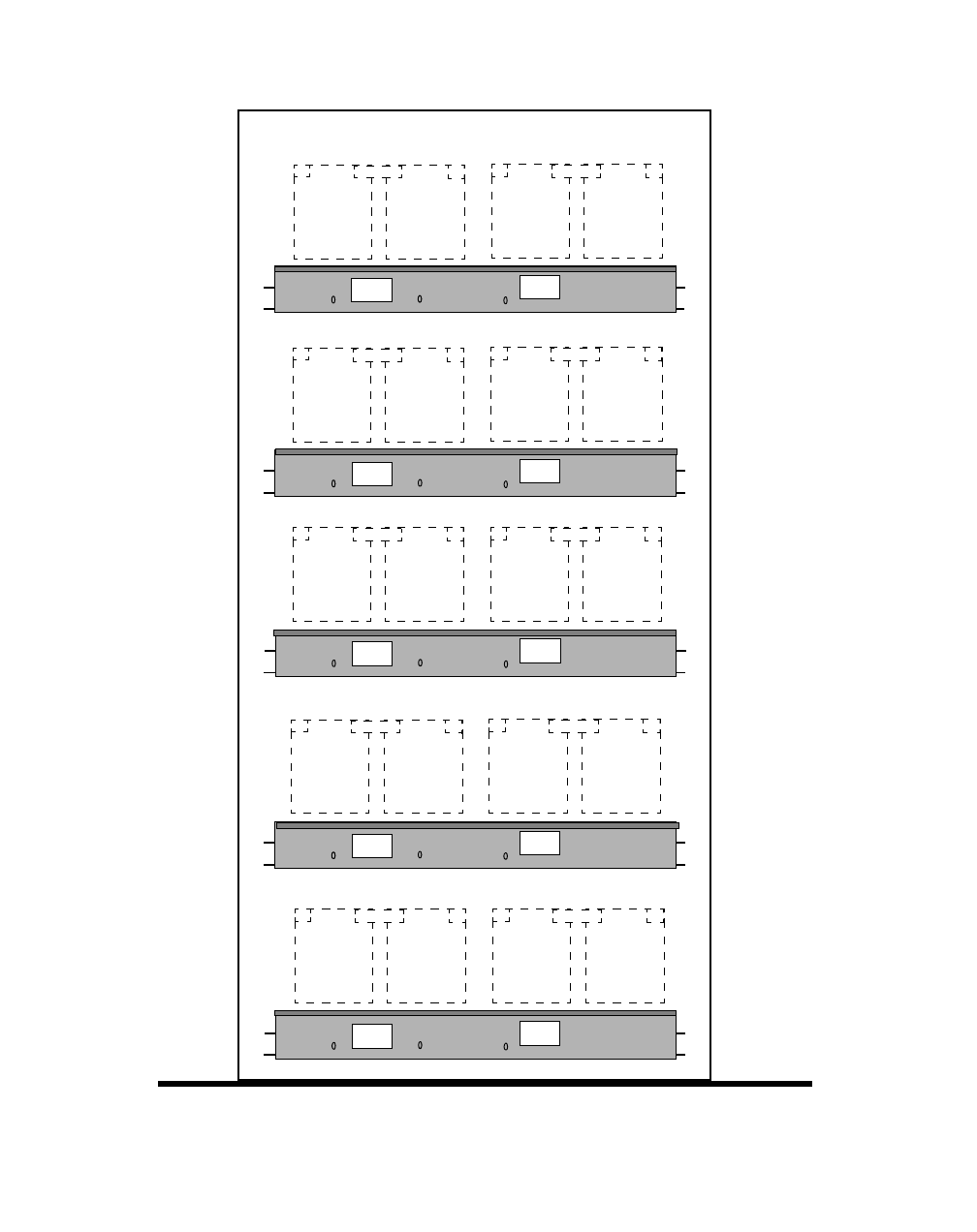
Component installation in the Modular Cell 4.0B and the
WNG24-BC battery cabinets
5- 51
Lucent Technologies – Proprietary
See notice on first page
401-703-454
FOA Draft Issue 1
January, 2006
............................................................................................................................................................................................................................................................
The figure below illustrates the12IR125 battery string positions and
battery numbers in the WNG24-BC battery cabinet.
BATTERY-
SHELF 5
BATTERY-
SHELF 3
BATTERY-
SHELF 1
FRONT VIEW
STRING 5 STRING 6
STRING 3 STRING 4
STRING 1 STRING 2
STRING 7 STRING 8
STRING 9 STRING 10
BATTERY-
SHELF 4
BATTERY-
SHELF 2
-+
+--+
+-
12 12
-+
+--+
+-
12 12
-+
+--+
+-
12 12
-+
+--+
+-
12 12
-+
+--+
+-
12 12
5-52 Lucent Technologies – Proprietary
See notice on first page 401-703-454
FOA Draft Issue 1
January, 2006
...........................................................................................................................................................................................................................................................
Component installation in the Modular Cell 4.0B and the
WNG24-BC battery cabinets
Place the 12IR125 batteries
on a shelf Use the following procedure to place batteries on a shelf, starting with
shelf 1 (bottom).
................................................................................................................................
............................................
1Remove the battery retaining brackets that are located on each of the
five battery cabinet shelves (if they will be populated with batteries),
and carefully lay them aside. Refer to the figure below.
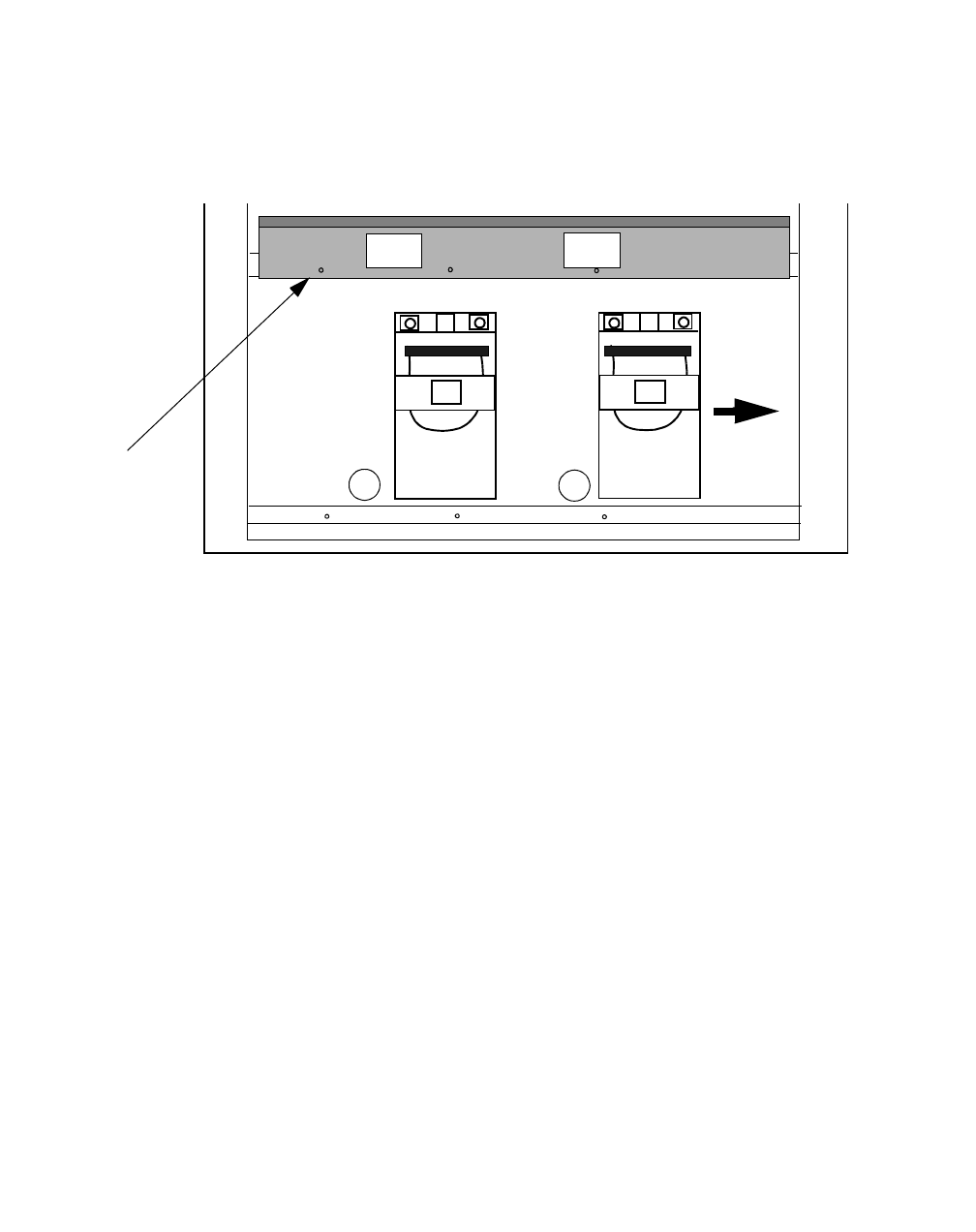
Component installation in the Modular Cell 4.0B and the
WNG24-BC battery cabinets
5- 53
Lucent Technologies – Proprietary
See notice on first page
401-703-454
FOA Draft Issue 1
January, 2006
............................................................................................................................................................................................................................................................
Important! Carefully slide a battery into the center position on
the bottom battery shelf (1). Then, slide the battery to the right
side of the cabinet shelf. Refer to item 1 in the figure below.
1
2
BATTERY
RETAINING
BRACKET
(1 of 5)
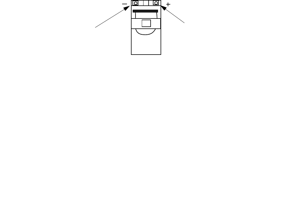
5-54 Lucent Technologies – Proprietary
See notice on first page 401-703-454
FOA Draft Issue 1
January, 2006
...........................................................................................................................................................................................................................................................
Component installation in the Modular Cell 4.0B and the
WNG24-BC battery cabinets
Important! When installed, the battery terminals on the front,
narrow end of the battery should face out of the cabinet. The
terminals should have a protective cap. Refer to the figure below.
................................................................................................................................
............................................
2Slide another battery into the center of the cabinet shelf. Also, slide this
battery to the right side of the shelf. Refer to the figure on Page 5-53,
item 2.
................................................................................................................................
............................................
3Slide the remaining the remaining two batteries onto the shelf.
................................................................................................................................
............................................
4Repeat steps 2 through 4 to install batteries on shelves 2 through 5, as
applicable.
................................................................................................................................
............................................
END OF STEPS
................................................................................................................................
.............................................
5Push all batteries to the rear of the battery shelf.
POSITIVE
BATTERY
TERMINAL
(-) BLACK RED (+)
NEGATIVE
BATTERY
TERMINAL
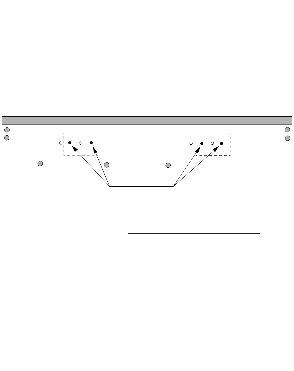
Component installation in the Modular Cell 4.0B and the
WNG24-BC battery cabinets
5- 55
Lucent Technologies – Proprietary
See notice on first page
401-703-454
FOA Draft Issue 1
January, 2006
............................................................................................................................................................................................................................................................
Adjust and secure the front
battery retaining brackets Important! When performing the following steps, the battery
retaining brackets must be installed as shown in the figure below
and the Step 5 figure on Page 5- 56. If the brackets were not
shipped installed in the orientation shown, they must be reversed
as described in the following steps.
Perform the following steps to correctly install the retaining brackets.
................................................................................................................................
............................................
1Observe the orientation of the battery retaining brackets shown in the
figure below. If the battery retaining brackets were not shipped in the
orientation shown, they must be reversed, which requires the battery
connectors to be moved to the other side of the bracket.
................................................................................................................................
............................................
2If the battery retaining brackets were shipped in the orientation shown,
reinstall the brackets as shown in the Step 5 figure on Page 5- 56, and
then skip to Connect positive battery cables to all battery strings on Page 5 -
57. If not, proceed to the next step, to reverse the brackets, which
requires the battery connectors to be moved to the other side of the
bracket.
................................................................................................................................
............................................
3Remove the nuts and washers from each battery connector and remove
the connectors from the bracket.
................................................................................................................................
............................................
4Remove the inside nuts, and then the connector mounting bolts from
their existing holes in the bracket.
12IR125 HOLES
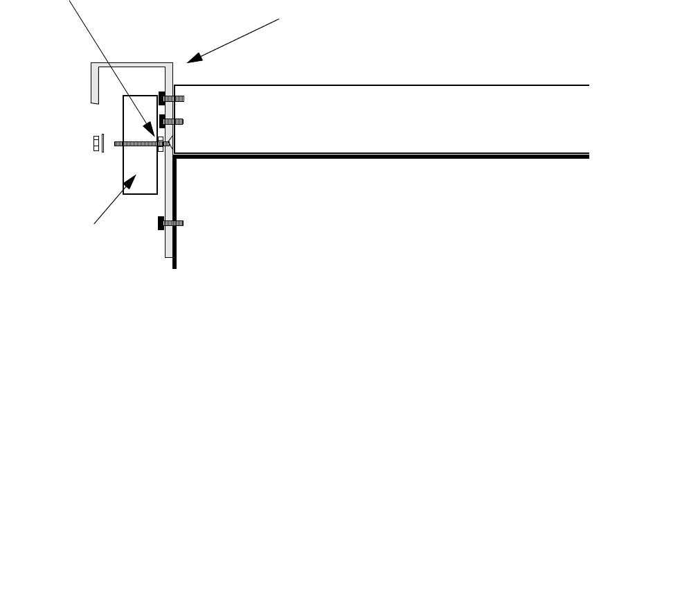
5-56 Lucent Technologies – Proprietary
See notice on first page 401-703-454
FOA Draft Issue 1
January, 2006
...........................................................................................................................................................................................................................................................
Component installation in the Modular Cell 4.0B and the
WNG24-BC battery cabinets
................................................................................................................................
............................................
5Reverse and reinstall the brackets as shown in the figure below.
Important! When performing the next step, note that after the
retaining bracket is reversed, the holes counter-sunk on the inside
of the bracket will be the correct holes to use. Also note that the
correct holes will always be the right-hand set viewed from the
front of the correctly installed bracket.
................................................................................................................................
............................................
6Reinstall the connector mounting bolts in the 12IR125 holes. Refer to
the figure on Page 5-55.
................................................................................................................................
............................................
7Replace the battery connectors on the brackets, and then reinstall the
END OF STEPS
................................................................................................................................
.............................................
brackets on the shelf. Refer to the figure above.
BATTERY
RETAINING
BRACKET
(1 of 5)
BATTERY SHELF
RIGHT SIDE VIEW
ANDERSON
CONNECTOR
INSIDE
NUT
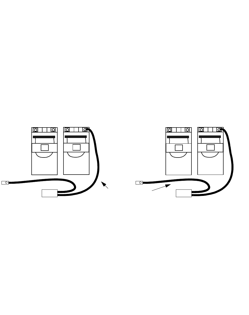
Component installation in the Modular Cell 4.0B and the
WNG24-BC battery cabinets
5- 57
Lucent Technologies – Proprietary
See notice on first page
401-703-454
FOA Draft Issue 1
January, 2006
............................................................................................................................................................................................................................................................
Connect positive battery
cables to all battery strings Important! When performing the following steps, do not
connect the negative battery cables. The negative battery cables
are not connected until after the interconnecting bus bars have
been installed in the next procedure.
Perform the following steps to connect the positive battery cables to all
battery strings.
................................................................................................................................
............................................
1Locate the ten battery cable assemblies. Refer to the figure below.
................................................................................................................................
............................................
2Starting with string 2 on the right side of shelf 1, remove the protective
cap from the terminals of battery 2. Refer to the figure below.
................................................................................................................................
............................................
3Apply antioxidant compound to the positive (+) terminal of battery 2 of
string 2.
+
-
STRING 2
BATTERY CABLE
ASSEMBLIES
(2 of 10)
+
-
12
(-) BLACK RED (+)
+
-
STRING 1
+
-
12
(-) BLACK RED (+)

5-58 Lucent Technologies – Proprietary
See notice on first page 401-703-454
FOA Draft Issue 1
January, 2006
...........................................................................................................................................................................................................................................................
Component installation in the Modular Cell 4.0B and the
WNG24-BC battery cabinets
................................................................................................................................
............................................
4Connect the positive (+) battery cable to the positive (+) terminal on
battery 2 of string 2, using the flat washer, lock washer and nut provided.
Refer to the figure on Page 5-60 for a top view of a typical battery cable
connection.
................................................................................................................................
............................................
5Torque the positive battery connections using an insulated socket and
torque wrench set at 60 in.-lb. (6.8 Nm). Do not use the torque
specifications provided in Chapter 1.
................................................................................................................................
............................................
6Repeat steps 1 through 5 for the number 2 battery in all remaining
END OF STEPS
................................................................................................................................
.............................................
battery strings.
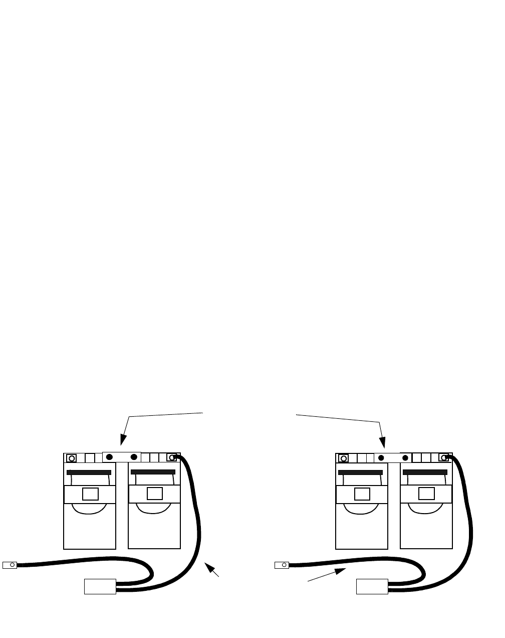
Component installation in the Modular Cell 4.0B and the
WNG24-BC battery cabinets
5- 59
Lucent Technologies – Proprietary
See notice on first page
401-703-454
FOA Draft Issue 1
January, 2006
............................................................................................................................................................................................................................................................
Attach interconnecting bus
bars to all battery strings Perform the following steps to attach interconnecting bus bars to all
battery strings.
................................................................................................................................
............................................
1Starting with string 2 on the right side of shelf 1, remove the protective
cap from the terminals of battery 1.
................................................................................................................................
............................................
2Remove the interconnecting bus bar from the kit that is provided with
each pair of batteries.
................................................................................................................................
............................................
3Polish the interconnecting bus bar.
................................................................................................................................
............................................
4Apply antioxidant compound to the interconnecting bus bar.
................................................................................................................................
............................................
5Apply antioxidant compound to the positive (+) terminal of battery 1
and the negative (-) terminal of battery 2 of string 2.
................................................................................................................................
............................................
6On string 2, place an interconnecting bus bar between the positive
terminal of the left-hand battery (#1) and the negative terminal of the
right-hand battery (#2). Refer to the figure below.
+
-
STRING 2
BATTERY CABLE
ASSEMBLIES
(2 of 10)
+
-
12
(-) BLACK RED (+)
+
-
STRING 1
+
-
12
(-) BLACK RED (+)
BATTERY STRING
BUS BARS
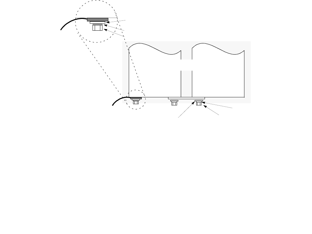
5-60 Lucent Technologies – Proprietary
See notice on first page 401-703-454
FOA Draft Issue 1
January, 2006
...........................................................................................................................................................................................................................................................
Component installation in the Modular Cell 4.0B and the
WNG24-BC battery cabinets
................................................................................................................................
............................................
7Connect the interconnecting bus bar using the flat washer, lock washer
and nut provided. Refer to the figure below, which illustrates the
interconnecting bus bar installation, including the installation order of
the washers.
................................................................................................................................
............................................
8Torque the two bus bar connections using an insulated socket and torque
wrench set at 60 in.-lb. (6.8 Nm). Do not use the torque specifications
provided in Chapter 1.
................................................................................................................................
............................................
END OF STEPS
................................................................................................................................
.............................................
9Repeat steps 1 through 8 for the remaining battery strings.
-
+
LOCK WASHER
BATTERY
CABLE
BATTERY
CABLE
BATTERY 2
BATTERY 1
LOCK WASHER
FLAT WASHER NUT OR BOLT
TOP VIEW
NUT OR BOLT
FLAT WASHER

Component installation in the Modular Cell 4.0B and the
WNG24-BC battery cabinets
5- 61
Lucent Technologies – Proprietary
See notice on first page
401-703-454
FOA Draft Issue 1
January, 2006
............................................................................................................................................................................................................................................................
Connect the negative
battery cables to all battery
strings
Perform the following steps to connect the negative battery cables to all
battery strings. Refer to the Step 4 figure on Page 5- 62
................................................................................................................................
............................................
1Apply antioxidant compound to the negative (-) terminal of battery 1 of
string 2.
................................................................................................................................
............................................
2Place the negative (-) battery cable on the negative (-) terminal on
battery 1, string 2, using the flat washer, lock washer and nut provided.
Refer to the figure on Page 5-60 for a top view of a typical battery cable
connection.
................................................................................................................................
............................................
3 Repeat steps 1 and 2 for all remaining battery strings.
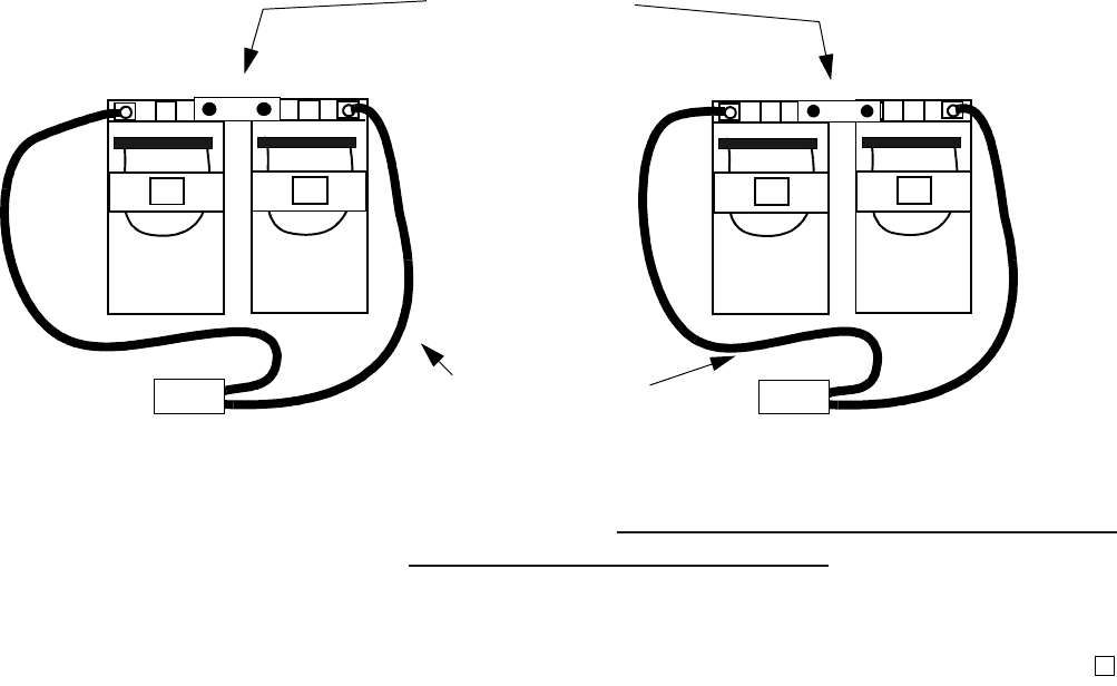
5-62 Lucent Technologies – Proprietary
See notice on first page 401-703-454
FOA Draft Issue 1
January, 2006
...........................................................................................................................................................................................................................................................
Component installation in the Modular Cell 4.0B and the
WNG24-BC battery cabinets
................................................................................................................................
............................................
4Torque the negative battery connections using an insulated socket and
torque wrench set at 60 in.-lb. (6.8 Nm). Do not use the torque
specifications provided in Chapter 1.
Important!Skip to How to route the thermal probe cable(s) and mount
the thermal probe(s) in the battery cabinets on Page 5 - 81 to continue
E
ND OF STEPS
....
.........................................................................................................
..................................................................
the installation.
+
-
STRING 2
BATTERY CABLE
ASSEMBLIES
(2 of 10)
+
-
12
(-) BLACK
RED (+)
+
-
STRING 1
+
-
12
(-) BLACK
RED (+)
BATTERY STRING
BUS BARS

Component installation in the Modular Cell 4.0B and the
WNG24-BC battery cabinets
5- 63
Lucent Technologies – Proprietary
See notice on first page
401-703-454
FOA Draft Issue 1
January, 2006
............................................................................................................................................................................................................................................................
.............................................................................................................................................................................................................................................................
How to install C-11 type batteries on type 2 battery shelves
Overview This section provides the instructions for the installation and
connection of the C-11 batteries. The instructions are the same for both
a first or second battery cabinet, except in the case of thermal probe
cables, where the exceptions are noted.
Place the C-11 batteries on a shelf 5 - 67
Reinstall the battery retaining brackets 5 - 70
Place the battery negative and positive bus bars 5 - 72
Connect the positive battery cables to the batteries 5 - 74
Attach the interconnecting bus bars 5 - 76
Connect the negative battery cables to the batteries 5 - 78
Install the insulating battery terminal covers 5 - 80

5-64 Lucent Technologies – Proprietary
See notice on first page 401-703-454
FOA Draft Issue 1
January, 2006
...........................................................................................................................................................................................................................................................
Component installation in the Modular Cell 4.0B and the
WNG24-BC battery cabinets
Read battery installation
procedure overview Important! In the event that the battery compartment is
removed from the primary cabinet because of an upgrade that adds
the A6 amplifier shelf (carriers 5 and 6), up to four spare L1
batteries will result. The end user may wish to use these batteries
in the battery cabinet, in which case a shelf must be left vacant.
Therefore, while performing any task involving a type 1 top
battery shelf (shelf 5), it may be desirable to plan on leaving that
shelf empty when installing the batteries.
The battery cabinet can contain up to 30 batteries that are wired in a
series/parallel configuration, which provides 24-volt backup. One
string (six batteries) of C-11 batteries can be mounted on each shelf of
the battery cabinet. Refer to the figure on Page 5-65.
Prepare the batteries for
installation To prepare the batteries, follow all appropriate standard practices for
the storage and handling of batteries. Complete the warranty
procedures and the following steps.
................................................................................................................................
............................................
1Check and record battery initial voltages.
................................................................................................................................
............................................
2Record all battery date codes.
................................................................................................................................
............................................
END OF STEPS
................................................................................................................................
.............................................
3Include this information with documentation supplied to the customer.
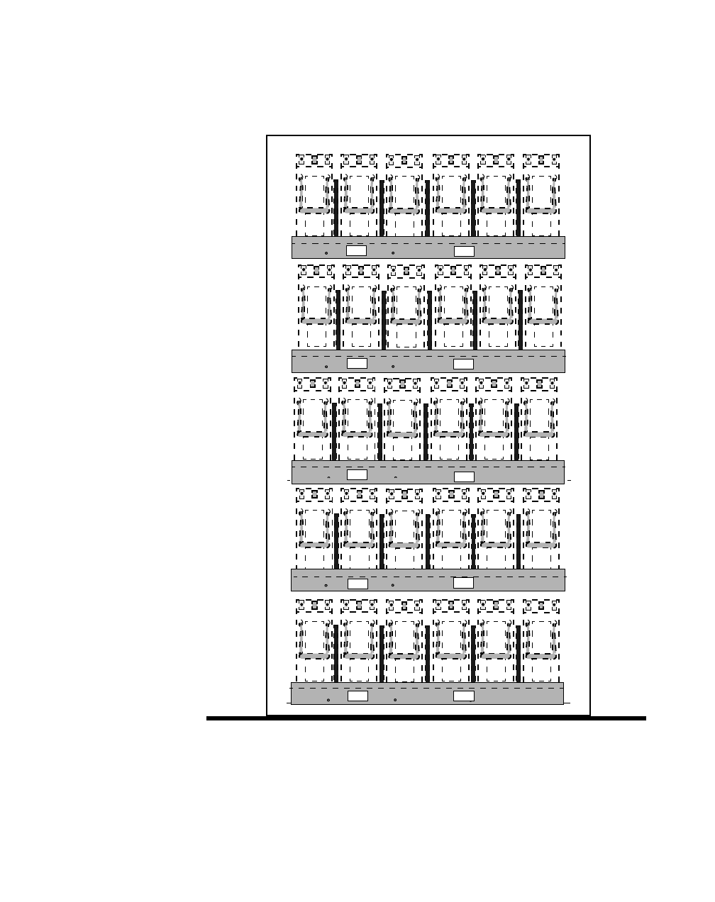
Component installation in the Modular Cell 4.0B and the
WNG24-BC battery cabinets
5- 65
Lucent Technologies – Proprietary
See notice on first page
401-703-454
FOA Draft Issue 1
January, 2006
............................................................................................................................................................................................................................................................
The figure below illustrates the battery string positions and battery
numbers for the C-11 batteries in the WNG24-BC battery cabinet.
123456
123456
123456
123456
123456
STRING 5
STRING 4
STRING 3
STRING 2
STRING 1
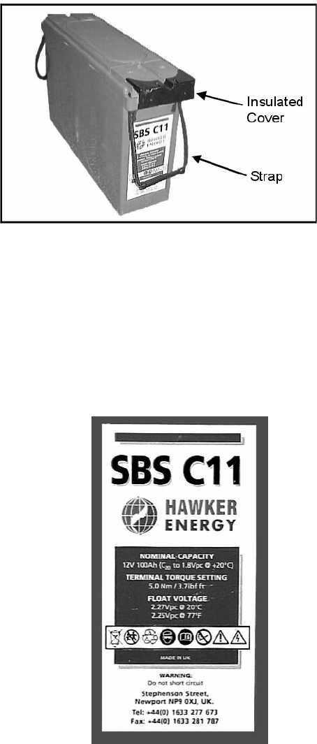
5-66 Lucent Technologies – Proprietary
See notice on first page 401-703-454
FOA Draft Issue 1
January, 2006
...........................................................................................................................................................................................................................................................
Component installation in the Modular Cell 4.0B and the
WNG24-BC battery cabinets
The battery terminals are located on one end of the battery. Positive and
negative terminals are clearly labeled “+” and “-”. Strap handles are
permanently attached to the battery. Refer to the figure below.
Important! To prevent an inadvertent electrical short during
battery installation, an insulated cover is factory-installed over the
terminals on the batteries. Do not remove this cover until you are
instructed to do so.
The following label is attached to the front of each battery. Refer to the
figure below.

Component installation in the Modular Cell 4.0B and the
WNG24-BC battery cabinets
5- 67
Lucent Technologies – Proprietary
See notice on first page
401-703-454
FOA Draft Issue 1
January, 2006
............................................................................................................................................................................................................................................................
CAUTION
The batteries weigh about 66 pounds (30 kg) each. Use care when lifting
them.
Place the C-11 batteries on
a shelf Use the following procedure to place batteries on a shelf, starting with
shelf 1 (bottom).
................................................................................................................................
............................................
1Remove the retaining brackets that are located on each of the five
battery cabinet shelves (if they will be populated with batteries), and
carefully lay them aside. Refer to the figure below.
Important! Before performing the next step, carefully observe
the installation of the battery retaining brackets before removing
them. Refer to the figure on Page 5-71 for the correct retaining
bracket installation for C-11 batteries. If they are not installed
properly for C-11 batteries, they must be reversed in the next
procedure block. This requires the removal of the battery
connectors. It may be easier to remove the battery connectors from
the retaining bracket prior to removal of the brackets from the
shelves.
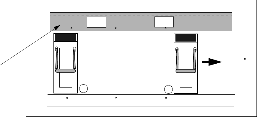
5-68 Lucent Technologies – Proprietary
See notice on first page 401-703-454
FOA Draft Issue 1
January, 2006
...........................................................................................................................................................................................................................................................
Component installation in the Modular Cell 4.0B and the
WNG24-BC battery cabinets
................................................................................................................................
............................................
2Lift and place one battery on the center of the bottom shelf, with the
battery terminals facing towards the front. Refer to the figure below.
................................................................................................................................
............................................
3Slide the first battery to the right-most position. Refer to the figure on
Page 5-68, item 1.
................................................................................................................................
............................................
4Place the left-most battery, and then the four center batteries. Refer to
the figure on Page 5-68, item 2.
1
2
BATTERY
RETAINING
BRACKET
(1 of 5)
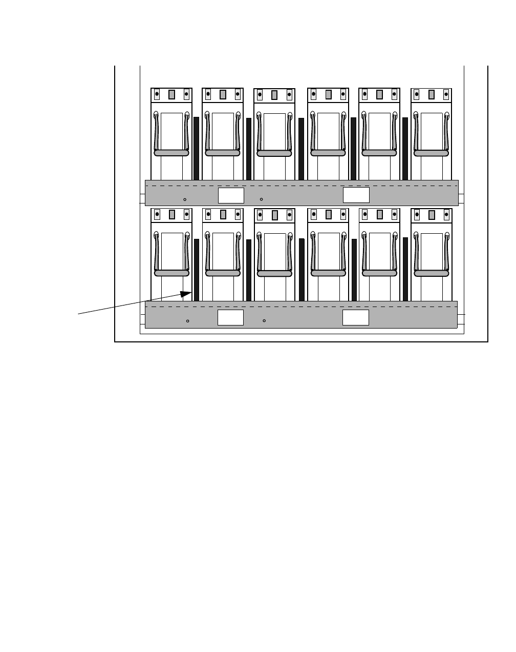
Component installation in the Modular Cell 4.0B and the
WNG24-BC battery cabinets
5- 69
Lucent Technologies – Proprietary
See notice on first page
401-703-454
FOA Draft Issue 1
January, 2006
............................................................................................................................................................................................................................................................
................................................................................................................................
............................................
5Install the battery spacers in the locations shown in the figure below
(five per shelf).
Important! Note the position numbers of the batteries in the
figure above, which will be used for identification purposes when
connecting the bus bars, battery cables, and the thermal probes.
................................................................................................................................
............................................
END OF STEPS
................................................................................................................................
.............................................
6Repeat steps 1 through 5 for the remaining battery shelves, if applicable.
123456
123456
S1
S2
BATTERY
SPACER
(1 of 10)
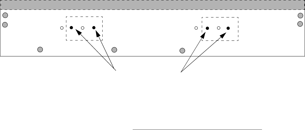
5-70 Lucent Technologies – Proprietary
See notice on first page 401-703-454
FOA Draft Issue 1
January, 2006
...........................................................................................................................................................................................................................................................
Component installation in the Modular Cell 4.0B and the
WNG24-BC battery cabinets
Reinstall the battery
retaining brackets Important! When performing the following steps, the battery
retaining brackets must be installed as shown in the Step 5 figure
on Page 5- 71, for C-11 batteries. If the brackets were not shipped
installed in the orientation shown, they must be reversed as
described in the following steps.
Perform the following steps to correctly install the retaining brackets.
................................................................................................................................
............................................
1Observe the orientation of the battery retaining brackets shown in the
figure below. If the battery retaining brackets were not shipped in the
orientation shown, they must be reversed, which requires the battery
connectors to be moved to the other side of the bracket. Refer to the
figure below and the Step 5 figure on Page 5- 71.
................................................................................................................................
............................................
2If the battery retaining brackets were shipped in the orientation shown,
reinstall the brackets as shown in the Step 5 figure on Page 5- 71, and
then skip to Place the battery negative and positive bus bars on Page 5 - 72
of this procedure. If not, proceed to the next step.
Important! If the battery retaining brackets were not shipped in
the orientation shown, they must be reversed, which requires the
battery connectors to be moved to the other side of the
brackets.The following steps provide the applicable instructions.
................................................................................................................................
............................................
3Remove the nuts and washers from each battery connector and remove
the connectors from the bracket.
C-11 HOLES