Nolangroup S p A NCOM10 Bluetooth hands-free kit User Manual
Nolangroup S.p.A. Bluetooth hands-free kit Users Manual
Contents
Users Manual
Firmware Version: 1.00
EN
USER INSTRUCTIONS AND SAFETY
Congratulations on your purchase of an N-Com product.
N-Com BX5 was made using the most advanced technologies and the best
materials. Long-running tests and thorough system development have allowed the
highest audio quality to be achieved.
For additional information about BX5, and to download high-definition instructions
as well as the latest
Firmware
version, visit the website www.n-com.it
REFERENCE STANDARDS
The products of the N-Com line are in compliance with standards as per the table
below:
BX5
The Bluetooth system complies with the main safety requirements
and other applicable provisions of Directive 99/5/CE, Directive
2002/95/CE, Directive 2011/65/CE, Directive 2002/96/CE
Battery
charger
Directive 2006/95, 2004/108, 2002/95/CE, 2011/65/CE, 2002/96/CE,
2009/125/CE
Battery Directive 2006/66
The Declarations of Compliance can be downloaded from the website www.n-
com.it (Download section).
FccID: XXXXX XXXXX
Bluetooth is a registered trademark property of Bluetooth SIG, Inc
Contents
1. WARNINGS AND SAFETY ...................................................................................................................4
1.1.Road safety ................................................................................................................................................................4
1.2.Switching on the system in safe environments ......................................................................................... 4
1.3.Interferences..............................................................................................................................................................4
1.4.Appropriate use .......................................................................................................................................................4
1.5.Qualified personnel................................................................................................................................................ 5
1.6.Accessories and batteries.................................................................................................................................... 5
1.7. Disposal ..................................................................................................................................................................... 6
2. CONTENT OF THE PACKAGING ........................................................................................................ 7
3. INSTALLATION...................................................................................................................................... 8
3.1.Preliminary operations – Jet helmets or Flip-up helmets ..................................................................... 8
3.2.Preliminary operations – Full-face helmets ................................................................................................. 8
3.3.Installing the microphone – jet helmets or flip-up helmets..............................................................10
3.4.Installing the microphone – full-face helmets .........................................................................................10
3.5.Installing the battery and the right-hand side speaker .......................................................................11
3.6.Positioning the e-box..........................................................................................................................................12
3.7.Installing the adhesive keyboard ...................................................................................................................13
4. REMOVING THE SYSTEM..................................................................................................................15
5. BASIC FUNCTIONS.............................................................................................................................16
5.1.N-Com Wizard and N-Com App....................................................................................................................16
5.1.Pairing up with Bluetooth devices.................................................................................................................16
6. MOBILE PHONE..................................................................................................................................17
6.1.Friend Number .......................................................................................................................................................17
6.2.Managing two mobile phones (or Bluetooth devices).........................................................................17
7. MUSIC VIA BLUETOOTH – A2DP BLUETOOTH PROTOCOLL ....................................................18
8. MUSIC VIA CABLE ..............................................................................................................................18
9. SATELLITE NAVIGATOR FOR MOTORCYCLES ..............................................................................18
9.1.Navigators on Smartphone (Smart Navi System)...................................................................................19
10. FM RADIO............................................................................................................................................19
11. AUTO ON / OFF FUNCTION.............................................................................................................19
12. RIDER-PASSENGER INTERCOM.......................................................................................................19
12.1.Rider-Passenger intercom pairing up .......................................................................................................19
12.2.Rider-Passenger intercom function............................................................................................................19
13. BIKE TO BIKE INTERCOM..................................................................................................................20
13.1.Bike-to-Bike Intercom Affiliation (Standard configuration) ............................................................20
13.2.Bike to bike intercom function .....................................................................................................................20
14. “UNIVERSAL INTERCOM” INTERCOM............................................................................................21
14.1.Pairing up the UNIVERSAL INTERCOM.....................................................................................................21
14.2.UNIVERSAL INTERCOM function.................................................................................................................21
15. SETTING MODE ..................................................................................................................................22
16. BATTERY AND RECHARGE................................................................................................................23
16.1.Low battery signal ..............................................................................................................................................23
16.2.Charging the system .........................................................................................................................................23
17. SCHEMA RIASSUNTIVO COMANDI – Configurazione standard..............................................24
18. LIMITED WARRANTY.........................................................................................................................26
18.1.Warranty coverage.............................................................................................................................................26
18.2.Exclusions and limitations of the coverage ............................................................................................26
18.3.Validity of this limited warranty ...................................................................................................................27
18.4.Procedure for the forwarding of claims ...................................................................................................27
18.5.Product identification .......................................................................................................................................28
19. WARRANTY REGISTRATION FORM................................................................................................29

4
1. WARNINGS AND SAFETY
Read this User Manual carefully, as well as the User Manuals for other N-Com kits that you will be using
with the N-Com BX5. Read the simple rules listed below. Failure to comply with these rules may lead to
dangerous situations.
Caution: The product cannot be used in official or non-official competitions, motordromes, circuits,
racing tracks and the like.
Caution: Installation of the N-Com BX5 system results in a weight increase of approximately 85g, which
is added to the weight of the helmet and of the other accessories.
Warning: The electronic components of the N-Com system mounted inside the helmet are not
waterproof. Consequently, make sure the inside of the helmet, including the comfort padding, does
not get wet in order to avoid damage to the system. If it does, remove the N-Com system and the
helmet comfort padding and let it air dry. Remove the battery from its housing and let it dry.
1.1. Road safety
Always obey all Traffic Regulations in force. While riding the motorcycle, your hands should always be
engaged in actually riding the vehicle. Any operation to the N-Com system must be carried out with the
vehicle stopped. Specifically:
Set your cell phone on automatic answer (see the cell phone instructions to do this).
If your cell phone is not equipped with this function, first stop your vehicle in a safe area, in
compliance with Traffic Regulations and then answer the call.
Do not make any calls while riding. Stop your vehicle in a safe place in compliance with Traffic
Regulations, and then make the call.
Adjust the volume so that it does not cause a disturbance or distraction while riding and at the
same time allows you to distinctively hear background noises.
Do not operate your cell phone or other devices connected to N-Com while riding your
motorcycle.
In all cases, obey the Traffic Regulations and remember that riding the motorcycle has absolute
priority over any other manoeuvre.
1.2. Switching on the system in safe environments
When using the N-Com system, comply with all limitations and instructions related to the use of
cell phones.
Do not turn on your cell phone or the N-Com system whenever their use is forbidden or when the
devices can cause interference or dangerous situations.
Turn off while refuelling. Do not use the N-Com system in filling stations. Do not use the device
near combustible materials or chemical products.
Turn off in proximity to explosive materials.
1.3. Interferences
Read this User Manual carefully, as well as the simple rules listed below. Failure to comply with these
rules may lead to dangerous situations.
1.4. Appropriate use
Use the device only in the normal position, as described in the product documentation. Do not attempt
to disassemble, tamper with or modify any part of the N-Com system.

BX5
5
Caution: Adjust the volume of the N-Com system (where provided) and of the audio sources connected
to it before you use the system on the road.
Caution: Adjusting the volume to very high levels may cause damage to your hearing.
Caution: Adjust the volume of the N-Com system (where provided) and of the audio sources connected
to it so as to avoid audio reproduction at high volumes. Constant exposure to high audio volumes
may damage your hearing.
Caution: An incorrect installation of the system in the helmet may alter the aerodynamic and safety
characteristics of the helmet itself, thus creating dangerous conditions. Install the N-Com system
according to the instructions provided in the product documentation. In case of doubt, please
contact your local N-Com dealer.
Warning: Listening to other equipment should not interfere with driving the vehicle, which must be the
top priority at all times. Carry out all operations on the electronic equipment and on the N-Com
system with the vehicle stopped, in compliance with Traffic Regulations.
Caution: The N-Com system allows reception of the FM radio signal. Any radio licence fees are to the
user’s charge.
1.5. Qualified personnel
Only qualified personnel can carry out technical assistance on this product. In case of any
malfunction, always turn to your local dealer.
The helmet is a safety device. Tampering with it and/or with the electronic system inside the
helmet, in addition to invalidating the product warranty, can also lead to dangerous situations.
1.6. Accessories and batteries
Only use the type of batteries, battery chargers and accessories approved by Nolan for the specific
model.
The use of a battery type different from the recommended one may lead to dangerous situations
and invalidate the warranty.
Contact your local dealer to see about the availability of approved accessories.
When disconnecting the power supply cable of any accessory or of the battery charger, always
grab and pull the plug not the cable.
Do not use batteries for purposes other than the prescribed ones.
Never use batteries or battery chargers that turn out to be damaged.
Do not short-circuit the battery.
Keep the battery at a temperature between 0° / +45°C (charging); -20° / +60 °C (in use).
Danger of fire or explosion: do not throw the batteries into a fire nor expose them to high
temperatures!
Do not throw out batteries together with household refuse. The batteries should be disposed of in
compliance with local regulations
Do not wear the helmet while the battery is recharging.
The helmet should never be left within the reach of unsupervised children in order to prevent
damage to their health caused by access to the batteries.
Battery XXXXX
Battery charger XXXXX

6
1.7. Disposal
Refer to this user manual and to manuals related to other parts of the N-Com system in order to
disassemble the system from the helmet. Once the system has been disassembled, dispose of it
according to the following instructions:
The presence of a crossed-out wheelie bin indicates that in the European Union the
product is subject to separate collection at the end of its useful life.
Do not dispose of these products together with undifferentiated urban waste.
The proper disposal of obsolete equipment contributes to preventing possible negative
consequences on people’s health and on the environment.
For more detailed information on the disposal of obsolete equipment, contact your municipality, a
waste disposal service or the store where the product was purchased.
BX5
7
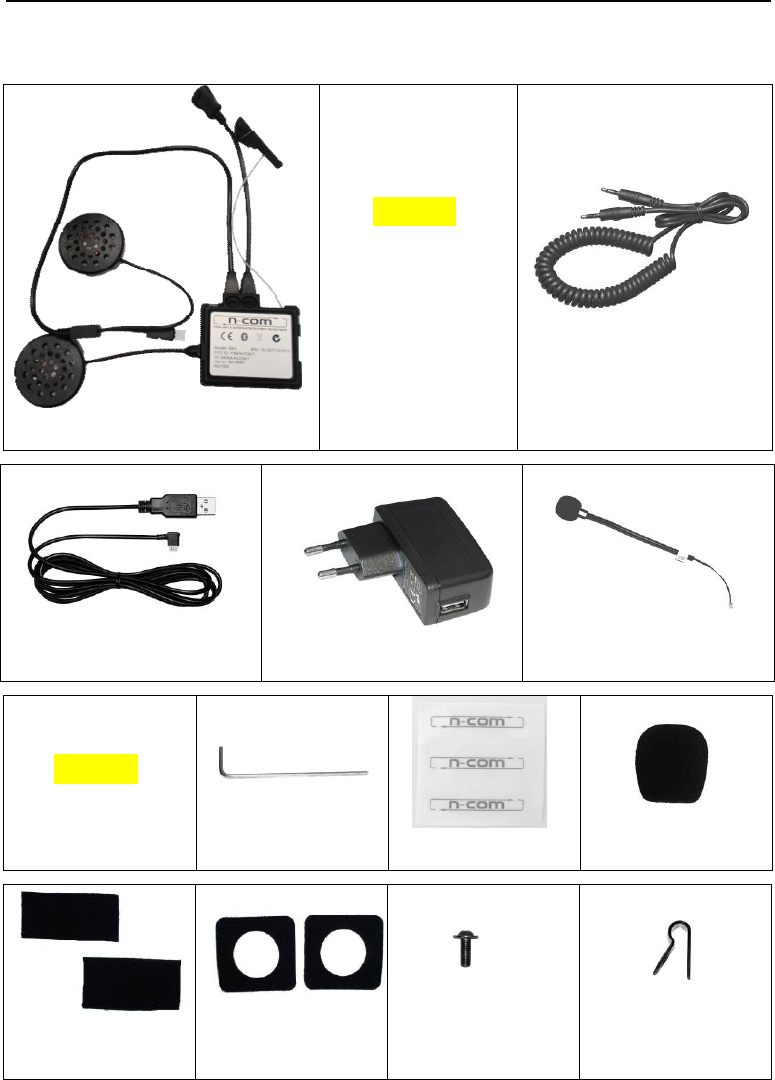
2. CONTENT OF THE PACKAGING
The N-Com BX5 package contains:
PICTURE
e-box
Adesive Keyboard
Multimedia Wire2
USB jack wire
Battery charger
Microphone
PICTURE
Rechargeable battery
Key
Adhesive strips for
cable
Microphone
foam
Microphone securing
stickers
Adhesive strips for
loudspeakers
Screw Microphone securing
clip
8
3. INSTALLATION
Important: Prior to installing the N-Com system, it is recommended to write down the identification
code affixed to the product (see chapter XX).
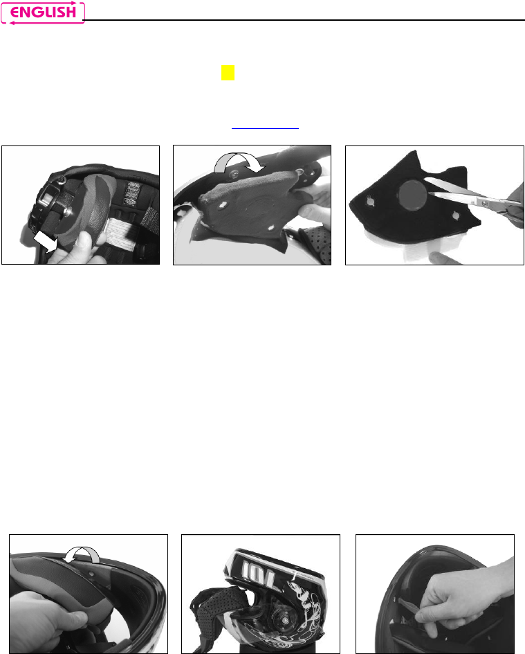
3.1. Preliminary operations – Jet helmets or Flip-up helmets
You can download the installation video from www.n-com.it X-Series Download section.
Open the helmet chin guard (only on Flip-up helmets).
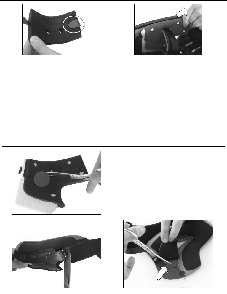
Pull out both comfort cheek pads, left and right, from the helmet. (Fig. 1)
Remove the noise reducers from the cheek pads (if present) and cut the insert using a pair of scissors,
following the pre-cut dots. Reposition the noise reducers in the removable cheek pads.
Take out the rear section of the comfort padding, pulling on the neck roll until it is released from the
shell. Reposition the padding on the outside of the helmet for the time being.
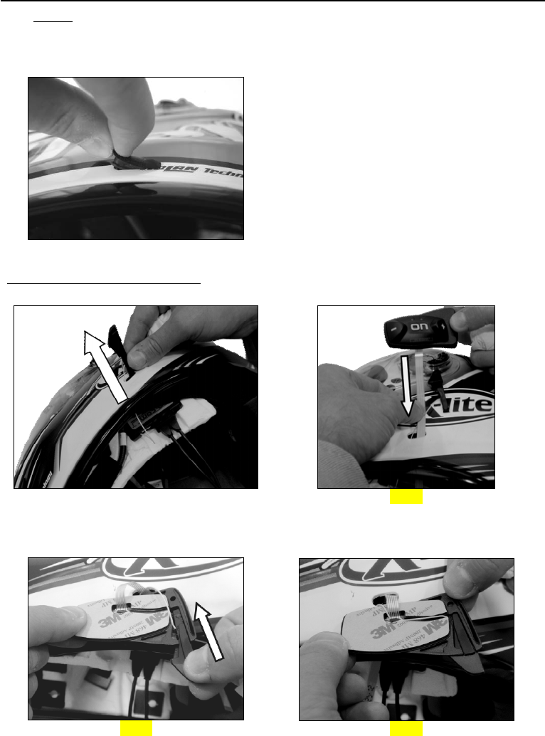
Unhook the press-stud of the polystyrene cheek pads by pulling toward the inside of the helmet (Fig.
2), then remove the cheek pad by pulling it upward.
Warning: in case the polystyrene cheek pad is damaged during this operation, please contact your local
dealer to replace it.
Cut out the round foam insert that covers the speaker housing from the polystyrene cheek pad using a
pair of scissors, following the pre-cut dots. (Fig. 3).
3.2. Preliminary operations – Full-face helmets
Fig. 1
Fig. 2
Fig. 3
Fig. 4
Fig. 5
Fig. 6a
BX5
9
Remove both comfort cheek pads, left and right, from the helmet (see specific instructions in the
helmet user manual). (Fig. 4)
Open the visor.
Remove the rear section of the comfort padding, pulling on the neck roll until it is released from the
shell (see specific instructions in the helmet user manual).Reposition the padding on the outside of
the helmet for the time being. (Fig. 5)
Remove the chin guard by pulling on the special red tab (Fig. 6a), then remove the plug from the
chin guard. (Fig. 6b)
Gently remove the polystyrene cheek pads by pulling them upward. (Fig. 7)
Warning: In case the polystyrene cheek pad is damaged during this operation, please contact your
local dealer to replace it.
In case the helmet is equipped with noise reducers on the comfort padding, lift them up.
Take the comfort padding, left-hand and right-hand side and, if equipped, cut the pre-drilled tab as
shown in fig. 9 and fig. 10.
Fig. 6b
Fig. 7
Fig. 8
Only for X701 – X603 - X602 helmets
:
Take the polystyrene cheek pads that have
just been removed and, using a pair of
scissors, remove the round insert by cutting
the fabric securing points. (Fig. 8)
Keep the foam used to cover the speakers
housing in case you wish to use the helmet
without the Bluetooth Kit system.
Fig. 9 helmets X702GT - X701 – X603
Fig. 10 helmets X702
10
3.3. Installing the microphone – jet helmets or flip-up helmets
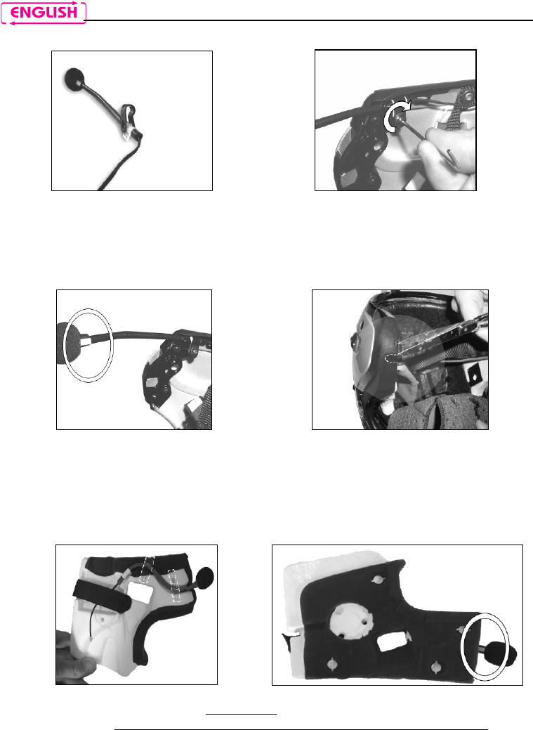
Set up the microphone by inserting the clip that holds it in place, being careful to position it
correctly. (Fig. 11)
Note: The flat part of the clip has to face upward when the microphone is positioned as shown in Fig. 11.
Position the microphone on the left side of the helmet, screwing the screw into the small frame.
(Fig.12 a/b) Make sure that the fluorescent band is facing the inside of the helmet.
On certain helmets, the housing for the microphone rod must be created by cutting out the helmet
border gasket along the pre-cut area. (Fig. 13)
3.4. Installing the microphone – full-face helmets
Take the polystyrene cheek pad (left-hand side) and position the microphone in its housing, as
shown in fig. 14, making sure that the fluorescent band stays facing the inside of the helmet. (Fig. 15)
Secure the microphone to the cheek pad using the “microphone securing stickers”, see Fig. 14.
Fig. 11
Fig. 12a
Fig. 12b
Fig. 13
Fig. 14
Fig. 15
BX5
11
3.5. Installing the battery and the right-hand side speaker
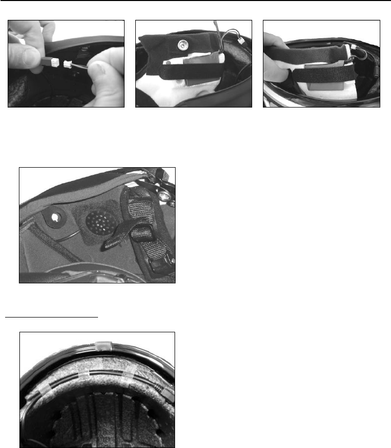
Connect the battery to the wiring system. (Fig. 16)
Position the battery in the right polystyrene cheek pad housing and secure it using the Velcro ribbon.
(Fig. 17 / 18)
Only for full-face helmets
: Insert the chin strap into the polystyrene cheek pad loop.
Fig. 16
Fig. 17
Fig. 18
Fig. 19
Position the right-hand side speaker in the
specific cheek pad housing and secure it using
the specific adhesive (Fig. 19).
Reposition the right polystyrene cheek pad in
its housing.
Fig. 20
Arrange the battery connector behind the
polystyrene cheek pad.
Arrange the cable behind the polystyrene shell
or inside the relevant housing.
12
3.6. Positioning the e-box
Fig. 21
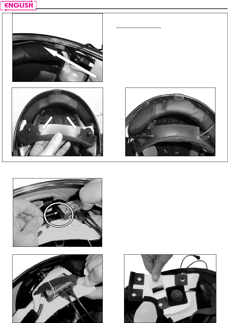
Only for X702 helmet
Position the battery connector and wiring
underneath the shell gasket (Fig. 21).
Cut along the pre-cut lines of the plastic tab on
the back of the comfort padding (Fig. 22).
Secure the wiring underneath the plastic tab.
Close the cut parts using the cable fixing
adhesives (Fig. 23).
Fig. 22
Fig. 23
Fig. 24
Connect the microphone to the e-box. (Fig. 24)
Position the e-
box in the left polystyrene cheek
pad housing. (Fig. 25)
Position the left-
hand side speaker in the cheek
pad housing and secure it using the specific
adhesive. (Fig. 26)
Fig. 25
Fig. 26
BX5
13
N.B.: BEFORE replacing the left polystyrene cheek pad, follow the instructions provided in the following
chapter.
3.7. Installing the adhesive keyboard
Fig. 27
Remove the N-
Com plug from the left side of the
helmet; to make this easier, it is recommended to
push the plug from t
he inside of the helmet. (Fig.
27)
Thoroughly clean the outside surface of the shell
to make sure that the adhesive keyboard sticks
properly. Before you apply the keyboard, make
sure that the shell area is completely clean and
grease or dirt free.
Only for Jet helmets or flip-up helmets
: Carry out the operation with the chin guard open.
Fig. 28
Fig. 29
Bring the antenna outside the helmet, passing it through the hole in the shell (Fig.28)
Pass the Flex cable of the keyboard through the hole in the outer shell. (Fig. 29)
Fig. 30
Fig. 31
Insert the antenna into the groove on the plastic support of the keypad (Fig. 30).
Push the antenna until you hear a click (Fig. 31).
14
Fig. 32
Fig. 33
Fig. 34
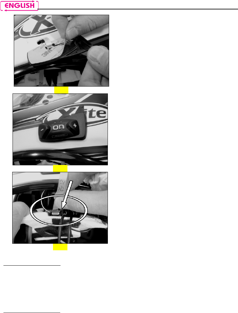
Remove the protective film from the back of
the adhesive keyboard
using the special tab.
(Fig. 32)
Pass the antenna and keypad cable completely
through, inside the helmet.
Apply the keyboard to the shell and press
down on its entire surface to make sure that
it
sticks properly. (Fig. 33)
Note: Make sure you do not glu
e the antenna and
keypad cable underneath the keypad support.
Note: In the event that the keyboard is not
positioned correctly, peel it off right away with
extreme care and repeat the positioning.
Note: It takes up to 24 hours for the keyboard to
stick completely. During this time, do not
expose the helmet to atmospheric agents.
Hook up the “flex” cable of the adhesive
keyboard to the e-box. (Fig. 34)
Reposition the left polystyrene cheek pad in its
housing.
Only for full-face helmets
: Insert the chin strap into the polystyrene cheek pad loop.
Reposition the left and right-hand side cheek pad by following the specific instructions provided in the
helmet user manual.
Hook the rear part of the comfort padding to the helmet.
Only for full-face helmets
: Insert the chin guard (microphone side), gently placing the microphone in its
housing. Then press down on the red tab until the chin guard is locked in place on the helmet.
BX5
15
Fig. 35
Only for flip-up / jet helmets
:
Secure the neck roll (left side
), being careful to slide the
neck roll plastic ring behind the microphone, then clicking
it in the press stud. (Fig. 35)
Secure the neck roll (right side) by hooking up the plastic
ring to the press-stud.
Warning: Always verify the proper length of your chinstrap and adjust it if necessary, referring to the
specific helmet instructions.
Warning: After the BX5 is installed on the helmet, make sure the microphone is properly positioned in
front of your mouth, if necessary adjusting the moveable element.
Warning: The wind protector, supplied as standard equipment with helmets that can be opened, may
make it more difficult to open and close the chin guard when the microphone is installed.
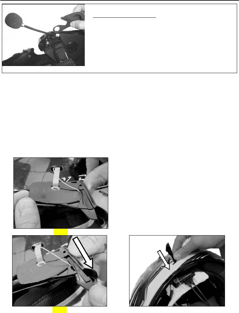
4. REMOVING THE SYSTEM
To remove the system from the helmet, proceed as for the installation, by removing the various parts.
Important: to remove the keypad support, proceed as follows.
Fig. 36
Remove the keypad support from the helmet
shell (Fig. 36);
Take out the antenna from the plastic support
of the keypad (Fig. 37);
Remove the Flex cable of the keypad from the
connector found on the electronic card;
Now completely remove the keypad support
from the helmet;
Bring the antenna inside the helmet, passing it
through the hole in the helmet shell. (Fig. 38).
The keypad support can be removed in case you decide to no longer use the system. However, it cannot
be reused again as it will have lost its adhesive properties. Contact your local dealer to purchase a new
keypad support that will stick properly to the helmet shell.
Fig. 37
Fig. 38
16
5. BASIC FUNCTIONS
System ON Press “on” and keep it pressed for about 2 seconds, until the LEDs turn on
and you hear a beep in the headset.
System OFF Press “on” and keep it pressed for about 4 seconds, until the LEDs turn off
and you hear a beep in the headset.
Increase Volume Briefly press “” to increase the volume. A double tone signals the highest
volume level.
Decrease Volume Briefly press “” to decrease the volume. A double tone signals the lowest
volume level.
5.1. N-Com Wizard and N-Com App
“N-Com Wizard” is the PC application that can be used to manage and configure the M5
system.
The programme can be downloaded from the Internet site www.n-com.it, in the
“Download” section. In order to use it, a helmet equipped with M5 must be connected to
the PC, using the USB cable supplied with the system.
The functions that can also be managed from the N-Com Wizard are listed here below with
the specific icon.
The N-Com system is preset to be hooked up to the “N-Com App”, the application compatible
with Android, iPhone and iPad that can be used to configure and operate the N-Com system
directly from a Smartphone.
With the N-Com App, you can carry out most of the functions included in the N-Com Wizard
program or, alternatively, it can be used as a wireless Bluetooth keypad.
The N-Com APP can be downloaded free of charge from Google Play or Apple Store.
For additional details, please visit the website www.n-com.it
The functions that can also be managed from the N-Com Wizard are listed here below with
the specific icon.
5.1. Pairing up with Bluetooth devices
Put the system in setting mode: press the “on” key and keep it pressed for 4 seconds, until the
red LED starts to flash quickly;
Turn on the search for Bluetooth devices (smartphone, GPS, MP3 reader) on the device;
Select the N-Com device. If a password is requested, enter 0000 (four zeros);
Connection between the two devices is established after a few seconds.
Note: The affiliation is stored in the helmet and in the cell phone and it is not lost when the two devices
are turned off. As a result it needs to be carried out only once.
Automatic Connection Once the Bluetooth device has been paired up, connection is automatic
when the system is turned on.
Manual Connection
In case connection is not automatically initiated after a few seconds, you
can connect from the Bluetooth device or by pressing “on” and “n” at the
same time.
BX5
17
6. MOBILE PHONE
Answering a phone call Briefly press any key when you hear the incoming call signal.
Voice call Press “on” and “n” at the same time.
Redial last number Press “on” and “n” and keep them pressed for about 2 seconds.
Dial Friend Number Press “n” and keep it pressed for about 2 seconds.
Hanging up/rejecting a
phone call Press “on” and keep it pressed for about 2 seconds.
Transferring a call from
helmet to mobile phone
To transfer an ongoing call from the helmet to the mobile phone, press
both “on” and “n” at the same time and keep them pressed for 2 seconds.
Manual phone connection Press “on” and “n” at the same time.
Manual phone
disconnection Press “” and keep it pressed for about 4 seconds.
Conference call function
When a call comes in on a mobile phone connected via Bluetooth to M5, the Rider-Pillion Passenger
intercom is temporarily turned off. However, if you wish to share the phone call with the other helmet,
simply turn on the intercom manually during the phone call.
Turning on the phone
conference call function During the phone call, briefly press “n”.
Turning off the phone
conference call function During the phone call, briefly press “n”.
N.B.: The Phone Conference Call function can only be used with a Rider-Pillion Passenger intercom
(channel 1) and not with Bike-to-Bike communication (channels 2-6).
6.1. Friend Number
When you use the N-Com Wizard or the N-Com App, you can choose a “Favorite
Number”, which you can be call by pressing a speed-dial button.
Calling the Friend Number Press the “n” key and keep it pressed for 2 second.
6.2. Managing two mobile phones (or Bluetooth devices)
The M5 system can be hooked up to two phones (or Bluetooth) devices at the same time.
The second phone (secondary device) can receive calls but not make them.
To pair up the second Bluetooth phone (secondary device):
press the “on” key and keep it pressed for 4 seconds, until the red LED starts to flash quickly
(setting mode);
Press the “on” key and keep it pressed for about 2 seconds.
Turn on the search for Bluetooth devices (smartphone, GPS, MP3 reader) on the device;
Select the N-Com system from the list
18
7. MUSIC VIA BLUETOOTH – A2DP BLUETOOTH PROTOCOLL
Play music (Play) Briefly press “on”.
Pause function (Pause) When the player is connected and playing music, press “on” for 2
seconds.
Next track (Skip) When the player is playing music, press “” for 2 about seconds.
Previous track (Rew) When the player is playing music, press “” for 2 about seconds.
Turning off the A2DP Press “on” and keep it pressed for about 4 seconds.
Turning on the A2DP The A2DP is already active when the system is turned on;
otherwise, press the “on” key briefly.
You can also configure these settings through Smartphone Android, iPhone and iPad thanks
to the dedicated N-Com App.
8. MUSIC VIA CABLE
Connect the mini USB connector of the Multimedia Wire (not included) to the helmet and the other end
to the audio device. A coloured band on the cable indicates the connector to be hooked up to the audio
device.
Turning on the cable
audio Press the “on” key three times.
Turning off the cable
audio Press “on” and keep it pressed for about 2 seconds.
9. SATELLITE NAVIGATOR FOR MOTORCYCLES
M5 system is compatible with the most common satellite navigators for motorcycles. For a list of
compatible models and additional details, visit the website www.n-com.it
To pair up a satellite navigator to the M5 system, follow the same procedure illustrated in Chapter 4.2.
GPS Conference Call Function
The Conference function allows you to keep the “Rider-Pillion Passenger” intercom open even while the
satellite navigator is giving instructions, thus preventing the intercom mode to be turned off every time
the navigator gives instructions. However, if you wish to activate the Conference GPS function, simply
turn on the intercom manually during the GPS directions.
Turning on the GPS Conference
function During the GPS directions, briefly press “n”.
Turning off the GPS Conference
function During the GPS directions, briefly press “n”.
At the end of the GPS communication, the intercom with the second helmet stays open and the
"Conference" setting is stored for future GPS communications.
N.B.: The GPS Conference function can only be used with the Rider-Pillion Passenger intercom (channel
1) and not with the Bike-to-Bike communication (channels 2-6).
BX5
19
9.1. Navigators on Smartphone (Smart Navi System)
By connecting the M5 system to a Smartphone, all navigator instructions are sent to the helmet through
the A2DP profile. During each navigator communication, the intercom via Bluetooth is automatically cut
off and subsequently restored when the navigator has stopped giving road instructions (SMART NAVI
SYSTEM function).
The Smart Navi System function can be turned off in Setting Mode (see Chapter 15).
10. FM RADIO
Turning on the radio Press the “on” key twice
Turning off the radio Press the “on” key twice.
New station automatic search Press “” and keep it pressed for 2 seconds.
Pre-setting a radio station (max. 6
stations) Press “” and keep it pressed for 4 seconds.
Changing radio stations (among
the pre-set ones) Press “” and keep it pressed for 2 seconds.
This function can also be turned on through PC using the “N-Com Wizard”
programme or through the “App N-Com” for Smartphone Android, iPhone, iPad.
11. AUTO ON / OFF FUNCTION
The system does not have to be turned on and off every time you use the motorcycle: thanks to the
triaxial accelerometer, if the helmet does no move for more than 30 seconds, the M5 system goes into
“deep sleep” mode. The system is completely turned on as soon as movement is detected.
If the system is in “deep sleep” mode for more than 7 days, it turns off completely. To turn it back on, the
“on” key need to be pressed.
12. RIDER-PASSENGER INTERCOM
12.1. Rider-Passenger intercom pairing up
Put both systems in Setting mode (press the “on” key and keep it pressed for 4 seconds, until
the red LED starts to flash quickly);
Press the “n” key briefly on one of the systems (Channel 1 pairing up).
12.2. Rider-Passenger intercom function
After carrying out the proper pair up procedure, turn on the two helmets. Intercom connection will be
established automatically (this will take a few seconds. Wait until you hear the vocal confirmation
message). If automatic connection is not possible, proceed with the manual connection.
Manual intercom connection With M5 turned on, briefly press “n”.
Manual intercom
disconnection With M5 turned on, briefly press “n”.
20
13. BIKE TO BIKE INTERCOM
The N-Com system is used for bike-to-bike communication up to a distance of about 800 m (open
terrain, no obstacles).
The M5 system entails the use of a default “STANDARD” commands configuration, or the use of a
“FRIENDS” configuration that can be turned on from the N-Com Wizard or dedicated App.
The difference between the two configurations lies in the number of motorcycles that can be hooked up:
the STANDARD configurations allows up to 3 different motorcycles to be hooked up to the M5 system,
while the FRIENDS configurations allows up to a total of 6.
Important: If you use the FRIENDS configuration, you need to visit the N-Com website and download the
dedicated commands diagram (section Download/Command Summary Diagram).
N.B.: The range and quality of the communication may vary significantly depending on the presence of
obstacles, weather conditions, magnetic fields.
N.B.: The range of the communication varies depending on the N-Com systems used.
13.1. Bike-to-Bike Intercom Affiliation (Standard configuration)
Put both systems A and B in Setting Mode (press the “on” key and keep it pressed for 4
seconds, until the red LED starts to flash quickly);
On system A, press the command related to the “setting position” where you wish to store
system B;
Pairing up CHANNEL 1 Briefly press “n”.
Pairing up CHANNEL 2 Press the “n” key twice.
Pairing up CHANNEL 3 Press the “n” key three times.
Pairing up CHANNEL 4 Briefly press “on”.
Pairing up CHANNEL 5 Press the “on” key twice.
Pairing up CHANNEL Press the “on” key three times.
N.B.: Channels 4-5-6 can be used with the FRIENDS configuration only.
CHANNEL 1 is typically used for the Rider-Pillion Passenger connection, however it can also be used for
the Bike-to-Bike intercom.
The use of CHANNEL 1 is different from the other channels due to the following specific characteristics:
When the systems are turned on, the intercom is automatically activated.
The Phone Conference function and the GPS Conference function can be used.
13.2. Bike to bike intercom function
How the Bike-to-Bike call works (Standard Configuration)
Connection CHANNEL 1 Briefly press “n”.
Call CHANNEL 2 Press the “n” key twice.
Call CHANNEL 3 Press the “n” key three times.
Disconnection of active intercom Briefly press “n”.
BX5
21
Con FRIENDS CONFIGURATION active:
Call CHANNEL 4 Briefly press “on”.
Call CHANNEL 5 Press the “on” key twice.
Call CHANNEL 6 Press the “on” key three times.
Disconnection of active intercom Briefly press “on”.
N.B.: In case the memory setting is empty, or the other helmet cannot be reached, an error tone will
sound in your helmet.
Taking a Bike to Bike call
Four calling tones will sound in the helmet receiving the Bike-to-Bike call, and all open audio functions
will be temporarily cut off (including the Rider – Pillion Passenger intercom, if any).
Answering a Bike to Bike phone call Briefly press any key when you hear the incoming call signal.
a. In case you take the call, communication is automatically established.
b. In case the call is not answered, the system returns to the situation prior to receiving the call.
14. “UNIVERSAL INTERCOM” INTERCOM
The N-Com M5 system can be connected via Bluetooth to intercom systems of other brands, thanks to
the UNIVERSAL INTERCOM function.
14.1. Pairing up the UNIVERSAL INTERCOM
The N-Com system can be paired up to an intercom of a different brand (from now on referred to as
Intercom B) as if it was a mobile phone.
1. Put the N-Com system in Setting Mode: press the “on” key and keep it pressed for 4 seconds,
until the red LED starts to flash quickly;
2. Put intercom B in the mobile phone pairing up mode (refer to the Intercom B manual);
3. When both systems are in the pair up mode (setting), on the N-Com system press the
command related to the “posizione di memoria” where you wish to store intercom B
(CHANNEL 1-3), see paragraph 13.2;
4. After a few seconds, Intercom B will emit the “phone connection” confirmation beep;
5. To turn on communication between the two, briefly press the “on” key on the N-Com system.
14.2. UNIVERSAL INTERCOM function
To turn on and off the audio between two helmets, proceed as follows:
From the N-Com system:
Connect or disconnect Intercom B as you would for a regular N-Com intercom (chapter 12-13)
Interco B receives a dialing one that must be answered with a phone reply command.
From an intercom of a different brand
Press the “Voice Call” command. The N-Com system receives a dialing tone; answer by pressing any key.
To disconnect the intercom, press “Voice Call” once again.

22
N.B.:
The N-systems keeps an active connection with a mobile phone or a GPS even during Bluetooth
communication with other intercom systems.
The intercom system connected to N-Com may not allow simultaneous connection to a mobile
phone.
15. SETTING MODE
All Bluetooth pair ups and other adjustments are carried out in this mode.
To put the system in Setting mode, press the “on” key and keep it pressed for 4 seconds, until the red
LED starts to flash quickly.
n on
N
+
on
▲ ▼
▲
+
▼
Turning on/off the RDS x1
Turning on/off the Smart Navi System 2 sec
Pairing up Secondary Phone 2 sec
Pairing up CHANNEL 1 x1
Pairing up CHANNEL 2 x2
Pairing up CHANNEL 3 x3
Pairing up CHANNEL 4 X
Pairing up CHANNEL 5 x2
Pairing up CHANNEL 6 x3
Pairing up the wireless keypad 4 sec
Reset 4 sec
*With Friends Configuration active.

BX5
23
16. BATTERY AND RECHARGE
16.1. Low battery signal
During its operation, the system alerts the user with a voice message when the battery is low. From the
first message, the system has a 1-hour autonomy. Warning is given every 10 minute.
16.2. Charging the system
To charge the system, hook it up to the battery charger or to a USB outlet powered with the USB-mini
USB cable supplied as standard equipment. The charge will take place as follows:
When you connect the BX5 system to the battery charger, the red LED of the Emergency Stop Light stars
to flash (at a frequency of 10 seconds). When the battery is charged, the LED changes to steady.
PICTURE
BX5 system
turned off
When the BX5 system is connected to the battery charger, the blue LED starts to flash
quickly. When the battery is charged, the blue LED becomes steady.
BX5 system
turned on
When the BX5 system is connected to the battery charger, the blue LED starts to flash
quickly. When the battery is charged, the blue LED goes back to its standard flashing.
N.B.: If the device has not been charged for a long time (a few months), it may not be possible to turn on
the system during the first few minutes of the charging, as the voltage may drop below the minimum
limit.
24
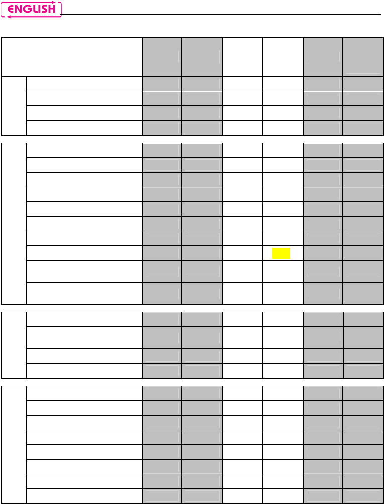
17. SCHEMA RIASSUNTIVO COMANDI – CONFIGURAZIONE STANDARD
Button
n on
N
+
on
+
Turning on
Turning off 6 sec
Increase Volume X
Basic
Functions
Decrease Volume X
Answer phone call X X X X
Voice call X
Redial last number 2 sec
Dial Friend Number 2 sec
Hang up/reject a phone call 2 sec
Call transfer 2 sec
Manual Device Connection X
Manual Device Disconnection 4 sec
Turning on the Conference
function X
Bluetooth Devices
Turning off the Conference
function X
Connection CHANNEL 1 X
Disconnection of active
intercom X
Calling CHANNEL 2 x2
Intercom
Calling CHANNEL 3 x3
Play music (Play) X
Pause Function (Pause) 2 sec
Next track (Forward) 2 sec
Previous track (REW) 2 sec
Enable A2DP profile X
Disable A2DP profile 4 sec
Activate audio via cable x3
Bluetooth Music / Cable
Deactivate audio via cable 2 sec

BX5
25
Button
n on
N
+
on
+
Turning on the Radio x2
Turning off the Radio x2
Automatic search for new
station 2 sec
Change station
(pre-set stations) 2 sec
Radio Menu
Pre-set station 4 sec
Pairing up mode (system
turned off)
Turning on/off the RDS X
Turning on/off the Smart
Navi System 2 sec
Pairing up secondary mobile
phone (or device) 2 sec
Pairing up CHANNEL 1 X
Pairing up CHANNEL 2 x2
Pairing up CHANNEL 3 x3
Pairing up CHANNEL 4 X
Pairing up CHANNEL 5 x2
Pairing up CHANNEL 6 x3
Setting*
Reset 4 sec
* All the Setting functions must be carried with the system in Setting Mode.
**With Friends Configuration active.

26
18. LIMITED WARRANTY
With this LIMITED WARRANTY CERTIFICATE, Nolangroup warrants this Product to be free from defects in
material and workmanship at the time of its original purchase by the buyer. We invite you to:
- Read the cautions pertaining to safety and proper use.
- Read the warranty terms and conditions.
- Keep the originals sales receipt. This must be shown in case of repairs covered by warranty. In these
cases, the product has to be taken back to the dealer where it was purchased.
18.1. Warranty coverage
If any defect covered by this limited warranty certificate is discovered within 2 (two) years from the
purchase date shown on the tax receipt, Nolangroup shall repair or replace the defective product
through its distribution network after having verified the defect. Nolangroup shall supply all the material
and labor that is reasonably required to remedy the defect, except in those cases where the damage is
caused by one of the items listed in the following paragraph “Exclusions and limitations of the
Coverage”.
18.2. Exclusions and limitations of the coverage
This warranty only covers defects in materials and manufacturing. Nolangroup shall not be considered
responsible for product defects that can be attributed, either partially or in full, to any other cause,
including but not limited to:
Defects or damages resulting from using the Product in conditions that differ from the usual ones.
Damages caused by improper use not conforming with normal operation in accordance with the
product operating and maintenance instructions provided by Nolangroup.
Negligence and normal wear of internal and external parts.
Any damage caused by an accident;
Any change or modification made to the helmet or to the N-com system by the user or by third
parties.
Colour changes or damages caused by exposure to harmful chemical products.
The use of incompatible accessories that are not part of the N-Com product range.
Moreover, the warranty does not cover product defects caused by fortuitous events, modifications or
adjustments, causes of force majeur or damages deriving from the product coming in contact with
liquids.
The internal helmet components are not and cannot be waterproof. Consequently, any improper
exposure to rain, humidity, food spillages or other liquids can result in damages to the N-Com
electronic devices, damages for which Nolangroup shall not be responsible.
This warranty does not include those parts subject to wear and tear such as, for example, the
rechargeable battery and the cables used for connection between the various N-Com systems or
between the N-Com systems and other devices.
Since Nolangroup does not supply the system on which the cell phones work, it shall not be
responsible for the operation, availability, coverage, services or range pertaining to the
aforementioned system.
Whenever the product is used in conjunction with accessories or equipment not supplied by
Nolangroup, Nolangroup shall not guarantee proper operation of the product/device combination,
nor will it accept requests for repairs or replacements under warranty in case the product is used in
such a way.

BX5
27
Nolangroup shall not be responsible in case the product presents limited capabilities due to the
operating mode of cell phones or of other accessories or equipment not supplied by Nolangroup.
Tampering with the internal electronic card or with other parts of the N-Com system shall invalidate the
warranty.
Moreover, the defects covered by this warranty do not include all those specific and subjective situations
that may come up during the active use of the helmet such as, for example, comfort problems while
riding or aerodynamic noises.
Nolangroup shall not be held responsible in any case for incidental or consequential damages (including,
without any limitation whatsoever, damages to one or more persons) resulting from non-fulfilment of
the obligations arising from this warranty as it pertains to Nolangroup products.
18.3. Validity of this limited warranty
This warranty is valid only if the enclosed warranty form is duly and completely filled out with the
following information:
Product identification code
Name and stamp of the authorized dealer.
Product purchase date.
Buyer’s name and address.
Nolangroup reserves itself the right to not carry out repairs under warranty if the aforementioned
information is removed or modified after the original purchase of the product from the dealer.
18.4. Procedure for the forwarding of claims
To forward a claim covered by this warranty, the buyer has to directly notify the dealer where the helmet
was purchased with regards to the defect, presenting at the same time the defective product, a copy of
the sales receipt and the Warranty registration form, duly filled out as instructed above.
PRIOR TO CONTACTING THE DEALER, WE RECOMMEND THAT YOU READ CAREFULLY THE USER
MANUAL ENCLOSED WITH THE PRODUCT.
AFTER 2 (TWO) YEARS FROM THE DATE OF PURCHASE, THIS LIMITED WARRANTY IS VOID FOR ALL
EFFECTS AND PURPOSES.
Repairs or maintenance under warranty do not extend the period of the warranty itself. Therefore, in
case the product or one of its components is replaced, this does not initiate a new warranty period, as
the purchase date of the original product shall be taken into account for warranty purposes.
Only for repairs or replacement of electronic components, in the event that Nolangroup proceeds to
repairing or replacing the product, said product shall enjoy a warranty period equal to the residual
portion of the original warranty or ninety (90) days from the repair date (the longer period being
considered).
The repair or replacement can be carried out even with regenerated components with equivalent
functions.
The replaced parts or components shall become property of Nolangroup.
THIS WARRANTY VOIDS AND REPLACES ANY OTHER WRITTEN OR VERBAL WARRANTIES PROVIDED
FOR BY THE LAW THAT CAN BE DEROGATED AT THE PARTIES’ WILL; SPECIFICALLY, NOLANGROUP DOES
NOT GRANT SPECIFIC WARRANTS OF MERCHANTABILITY OR FITNESS FOR A PARTICULAR PURPOSE. IN
NO CASE SHALL NOLAN BE LIABLE FOR INCIDENTAL OR CONSEQUENTIAL DAMAGES INCLUDING BUT

28
NOT LIMITED TO LOST PROFITS OR COMMERCIAL DAMAGES, TO THE FULL EXTENT THOSE DAMAGES
CAN BE DISCLAIMED BY THE LAW.
NOLANGROUP RESERVES ITSELF THE RIGHT TO MODIFY, AT ANY TIME AND WITHOUT ADVANCE
NOTICE, THE PRODUCT CHARACTERISTICS, FUNCTIONS, COMPATIBILITY AND SOFTWARE.
Some Countries do not allow the exclusion or limitation of incidental or consequential damages, or the
limitation of the duration of implied warranties; as a result of this, the previous limitations and exclusions
may not be applicable to you.
This warranty does not have any effect on the customer’s legal rights under the national jurisdiction in
force or on the consumer’s rights towards the dealer sanctioned by the purchase/sale contract.
This warranty is valid throughout the European territory, and it represents the only express warranty
provided by Nolangroup in relation to the sale of its own products. This warranty does not affect the
rights to which the buyer is entitled and which are expressly provided for by Directive 1999/44/CE.
This warranty does not affect the consumer’s rights provided for by the law, and specifically by the
provisions of Legislative Decree 2 February 2002 n. 24.
18.5. Product identification
N-Com products are identified by means of a code that allows
product traceability and identification.
The identification code is listed on the adhesive label applied to the
BX5 system and on the outside of the sales package.
PICTURE
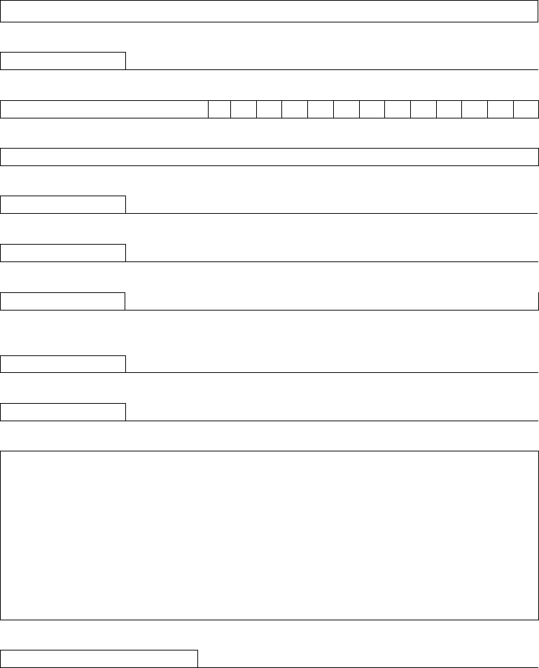
19. WARRANTY REGISTRATION FORM
Product name BX5
Identification code
Buyer’s Information
Name
Last name
Address
Phone
e-mail
Dealer’s stamp
Date of purchase

Printed on recycled paper
N-Com BX5 - 14/10/2014 14:55:00
www.n-com.it