Nolangroup S p A NCOM15 Nolan Communication System (B6/B6L) User Manual
Nolangroup S.p.A. Nolan Communication System (B6/B6L)
UserManual.wiki
>
Nolangroup S p A
>
NCOM15 User Manual
User Manual
Navigation menu
Upload a User Manual
Namespaces
Wiki Guide
HTML
PDF
Info
Views
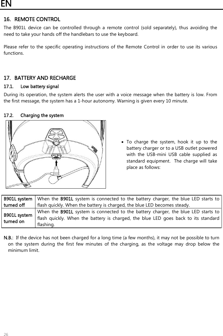
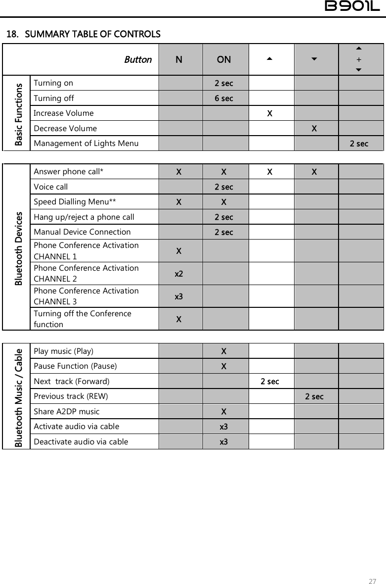
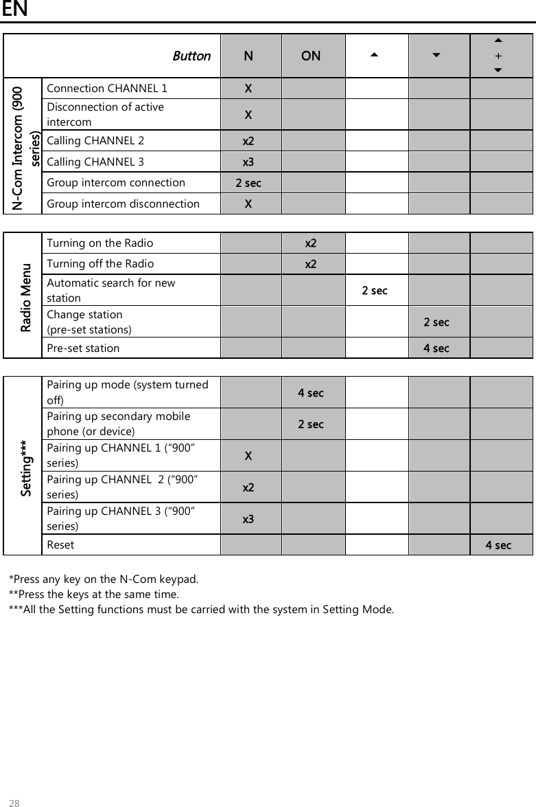
User Manual
Discussion / Help
Navigation