Nolangroup S p A NCOM15 Nolan Communication System (B6/B6L) User Manual
Nolangroup S.p.A. Nolan Communication System (B6/B6L)
User Manual
EN
B901L “R” - Fw 1.0X - 19/05/2017
USER INSTRUCTIONS AND SAFETY
Congratulations on your purchase of an N-Com product.
N-Com B901L was made using the most advanced technologies and the best
materials. Long-running tests and thorough system development have allowed
the highest audio quality to be achieved.
For additional information about B901L, and to download high-definition
instructions as well as the latest Firmware version, visit the website www.n-com.it
Firmware version: 1.0
REFERENCE STANDARDS
The products of the N-Com line are in compliance with standards as per the table below:
B901L
The Bluetooth system complies with the main safety requirements and
other applicable provisions of Directive 99/5/CE, Directive 2009/65/EC,
Directive 2011/65/CE, Directive 2012/19/EU
Battery
charger
Directive 2006/95, 2004/108, 2009/65/EC, 2011/65/EC, 2012/19/EU,
2009/125/CE
Battery
Directive 2006/66/CE
The Declarations of Compliance can be downloaded from the website www.n-com.it (Download
section).
FCC ID: Y6MNCOM15 IC: 9455A-NCOM15 R-NZ
The Bluetooth® word mark and logos are registered trademarks owned by the Bluetooth
SIG, Inc. and any use of such marks by N-Com is under license. Other trademarks and
trade names are those of their respective owners.
2
Model: B901L R
Contents
1. WARNINGS AND SAFETY ................................................................................................................... 4
1.1.Road safety ................................................................................................................................................................................................. 4
1.2.Switching on the system in safe environments ........................................................................................................................ 4
1.3.Interferences .............................................................................................................................................................................................. 4
1.4.Appropriate use ....................................................................................................................................................................................... 4
1.5.Qualified personnel ................................................................................................................................................................................ 5
1.6.Accessories and batteries .................................................................................................................................................................... 5
1.7. Disposal.................................................................................................................................................................................................. 5
2. CONTENT OF THE PACKAGING ........................................................................................................ 6
3. INSTALLATION ON THE HELMET ...................................................................................................... 7
3.1.Preparing the ESS system.................................................................................................................................................................... 8
3.2.Installing the ESS system on the helmet...................................................................................................................................... 9
3.3.Positioning the ESS system on the helmet .............................................................................................................................. 12
3.4.Removing the B901L system from the helmet ...................................................................................................................... 12
4. BASIC FUNCTIONS ............................................................................................................................. 14
4.1.Volume adjustment ............................................................................................................................................................................. 14
4.2.Auto On / Off function ...................................................................................................................................................................... 14
4.3.N-Com EASYSET ................................................................................................................................................................................... 14
5. CONFIGURATION MENU .................................................................................................................. 15
6. PAIRING UP WITH MOBILE PHONES OR OTHER BLUETOOTH DEVICES ................................ 16
7. MOBILE PHONE .................................................................................................................................. 16
7.1.Speed dialling ........................................................................................................................................................................................ 16
7.2.Conference call function ................................................................................................................................................................... 17
8. MANAGING TWO MOBILE PHONES (OR BLUETOOTH DEVICES) ............................................ 18
9. MUSIC VIA BLUETOOTH ................................................................................................................... 18
9.1.Sharing music via Bluetooth (
A2DP Sharing
) ......................................................................................................................... 18
10. MUSIC VIA CABLE .............................................................................................................................. 19
11. SATELLITE NAVIGATOR FOR MOTORCYCLES .............................................................................. 19
13. LED SIGNALLING LIGHTS .................................................................................................................. 20
13.1.Emergency Stop Signal ESS (mode 1) ..................................................................................................................................... 20
13.2.Rear Light (mode 2) .......................................................................................................................................................................... 20
13.3.Poor visibility light (mode 3)....................................................................................................................................................... 21
14. N-COM INTERCOM (SERIES “900”) ................................................................................................ 21
14.1.Intercom pairing up.......................................................................................................................................................................... 21
14.2.Intercom function (one-to-one connection) ........................................................................................................................ 21
14.3.
Smart Conference
(Group Intercom) ....................................................................................................................................... 22
15. “UNIVERSAL INTERCOM” INTERCOM ............................................................................................ 23
15.1.Pairing up the UNIVERSAL INTERCOM ................................................................................................................................... 23
15.2.Universal Intercom Function ........................................................................................................................................................ 24
15.3.Universal Conference (chain intercom) ................................................................................................................................... 24
16. REMOTe control ................................................................................................................................. 26
17. BATTERY AND RECHARGE ................................................................................................................ 26
17.1.Low battery signal ............................................................................................................................................................................. 26
17.2.Charging the system ........................................................................................................................................................................ 26
18. SUMMARY TABLE OF CONTROLS .................................................................................................. 27
19. LIMITED WARRANTY ......................................................................................................................... 29
19.1.Warranty coverage............................................................................................................................................................................ 29
19.2.Exclusions and limitations of the coverage .......................................................................................................................... 29
19.3.Validity of this limited warranty.................................................................................................................................................. 30
19.4.Procedure for the forwarding of claims ................................................................................................................................. 30
19.5.Product identification ...................................................................................................................................................................... 30
20. WARRANTY REGISTRATION FORM ................................................................................................ 31

EN
4
1. WARNINGS AND SAFETY
Read this User Manual carefully, as well as the simple rules listed below. Failure to comply with these rules may lead
to dangerous situations.
Caution: The product cannot be used in official or non-official competitions, motordromes, circuits, racing tracks and
the like.
Caution: Installation of the N-Com B901L system results in a weight increase of approximately 120g, which is added
to the weight of the helmet and of the other accessories.
Warning: The electronic components of the N-Com system mounted inside the helmet are not waterproof.
Consequently, make sure the inside of the helmet, including the comfort padding, does not get wet in order to
avoid damage to the system. If it does, remove the N-Com system and the helmet comfort padding and let it
air dry. Remove the battery from its housing and let it dry.
1.1. Road safety
Always obey all Traffic Regulations in force. While riding the motorcycle, your hands should always be engaged in
actually riding the vehicle. Any operation to the N-Com system must be carried out with the vehicle stopped.
Specifically:
Set your cell phone on automatic answer (see the cell phone instructions to do this).
If your cell phone is not equipped with this function, first stop your vehicle in a safe area, in compliance with
Traffic Regulations and then answer the call.
Do not make any calls while riding. Stop your vehicle in a safe place in compliance with Traffic Regulations, and
then make the call.
Adjust the volume so that it does not cause a disturbance or distraction while riding and at the same time allows
you to distinctively hear background noises.
Do not operate your cell phone or other devices connected to N-Com while riding your motorcycle.
In all cases, obey the Traffic Regulations and remember that riding the motorcycle has absolute priority over any
other manoeuvre.
The B901L system is equipped with an emergency brake light (ESS – Emergency Stop Signal). The ESS system IS
NOT intended to replace the stop or brake lights fitted on the motorcycle, consequently its operation alone is not
enough for proper brake signaling.
Make sure that the use of the emergency brake light (ESS – Emergency Stop Signal) is not in conflict with the
regulations in force in the country where you will be travelling.
1.2. Switching on the system in safe environments
When using the N-Com system, comply with all limitations and instructions related to the use of cell phones.
Do not turn on your cell phone or the N-Com system whenever their use is forbidden or when the devices can
cause interference or dangerous situations.
Turn off while refuelling. Do not use the N-Com system in filling stations. Do not use the device near combustible
materials or chemical products.
Turn off in proximity to explosive materials.
1.3. Interferences
All phones and devices with wireless signal transmission are subject to interferences that may affect the
performance of the device connected to them. These interferences are not ascribable to a defect of the N-Com
system.
1.4. Appropriate use
Use the device only in the normal position, as described in the product documentation. Do not attempt to
disassemble, tamper with or modify any part of the N-Com system.
Caution: Adjust the volume of the N-Com system (where provided) and of the audio sources connected to it before
you use the system on the road.
B901L
5
Caution: Adjusting the volume to very high levels may cause damage to your hearing.
Caution: Adjust the volume of the N-Com system (where provided) and of the audio sources connected to it so as to
avoid audio reproduction at high volumes. Constant exposure to high audio volumes may damage your
hearing.
Caution: An incorrect installation of the system in the helmet may alter the aerodynamic and safety characteristics of
the helmet itself, thus creating dangerous conditions. Install the N-Com system according to the instructions
provided in the product documentation. In case of doubt, please contact your local N-Com dealer.
Warning: Listening to other equipment should not interfere with driving the vehicle, which must be the top priority
at all times. Carry out all operations on the electronic equipment and on the N-Com system with the vehicle
stopped, in compliance with Traffic Regulations.
1.5. Qualified personnel
Only qualified personnel can carry out technical assistance on this product. In case of any malfunction, always
turn to your local dealer.
The helmet is a safety device. Tampering with it and/or with the electronic system inside the helmet, in addition
to invalidating the product warranty, can also lead to dangerous situations.
1.6. Accessories and batteries
Only use the type of batteries, battery chargers and accessories approved by Nolan for the specific model.
The use of a battery type different from the recommended one may lead to dangerous situations and invalidate the
warranty.
Contact your local dealer to see about the availability of approved accessories.
When disconnecting the power supply cable of any accessory or of the battery charger, always grab and pull the
plug not the cable.
Do not use batteries for purposes other than the prescribed ones.
Never use batteries or battery chargers that turn out to be damaged.
Do not short-circuit the battery.
Keep the battery at a temperature between 0° / +32°C (charging): -20° / +55°C (in use).
Danger of fire or explosion: do not throw the batteries into a fire nor expose them to high temperatures!
Do not throw out batteries together with household refuse. The batteries should be disposed of in compliance with
local regulations
Do not wear the helmet while the battery is recharging.
The helmet should never be left within the reach of unsupervised children in order to prevent damage to their health
caused by access to the batteries.
Battery
Lithium 3,7V – 1000 mAh
Battery charger
S-
TR
-
009L
100/240V – 50/60 Hz 5V - 0.5 A
1.7. Disposal
Refer to this user manual and to manuals related to other parts of the N-Com system in order to disassemble the
system from the helmet. Once the system has been disassembled, dispose of it according to the following
instructions:
The presence of a crossed-out wheelie bin indicates that in the European Union the product is
subject to separate collection at the end of its useful life.
Do not dispose of these products together with undifferentiated urban waste.
The proper disposal of obsolete equipment contributes to preventing possible negative consequences on
people’s health and on the environment.
For more detailed information on the disposal of obsolete equipment, contact your municipality, a waste disposal
service or the store where the product was purchased.
PL523450P
EN
6
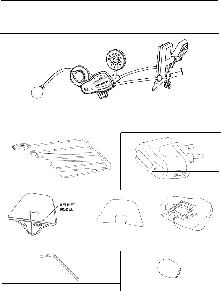
2. CONTENT OF THE PACKAGING
The N-Com B901L package contains:
N-Com B901L system
Mini
USB
wire
Battery charger
Helmet adapters
Helmet adapter double-
sided adhesive tape
Keypad adapters for
N87, N105
Key
Microphone foam
B901L
7
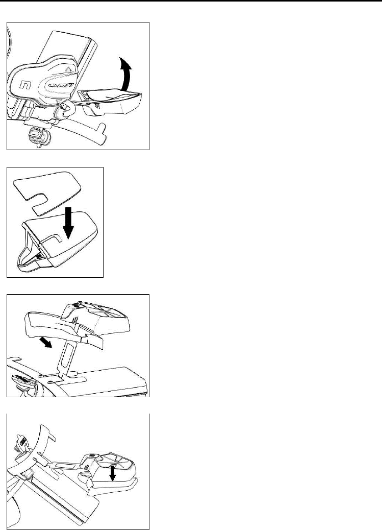
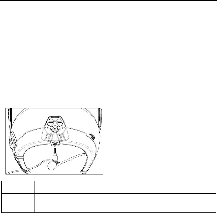
3. INSTALLATION ON THE HELMET
Important: Prior to installing the N-Com system, it is recommended to write down the identification
code affixed to the product (see chapter 19.5).
You can download the installation video from www.n-com.it N-Com / Download section.
Before you install the B901L system on the helmet, make sure it turns on properly. Press the “ON”
key for about 2 seconds, until the blue LED on the key pad lights up and you hear a beep in the
headset. Proceed with the installation.
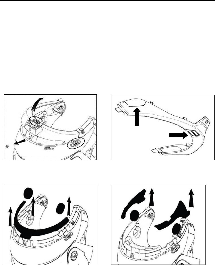
Remove the cheek padding (see helmet instructions).
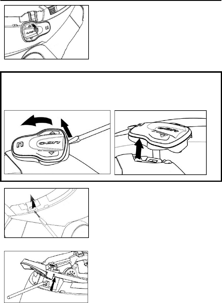
Remove the helmet edge gasket using the special tool (Fig. 1).
Completely remove the gasket as shown in Fig. 1; by doing so you also remove the padding.
Remove the “N-Com” plugs found at the back of the shell gasket and on the left side of the
helmet.
Fig. 1
Fig. 1 – ONLY FOR N87 – N105 HELMET
Prior to installing the N-Com system, remove any filling foam material found in the helmet.
Option 1
Option 2
N.B.: Keep the filling material in case you wish to use the helmet without the N-Com system in the
future.
EN
8
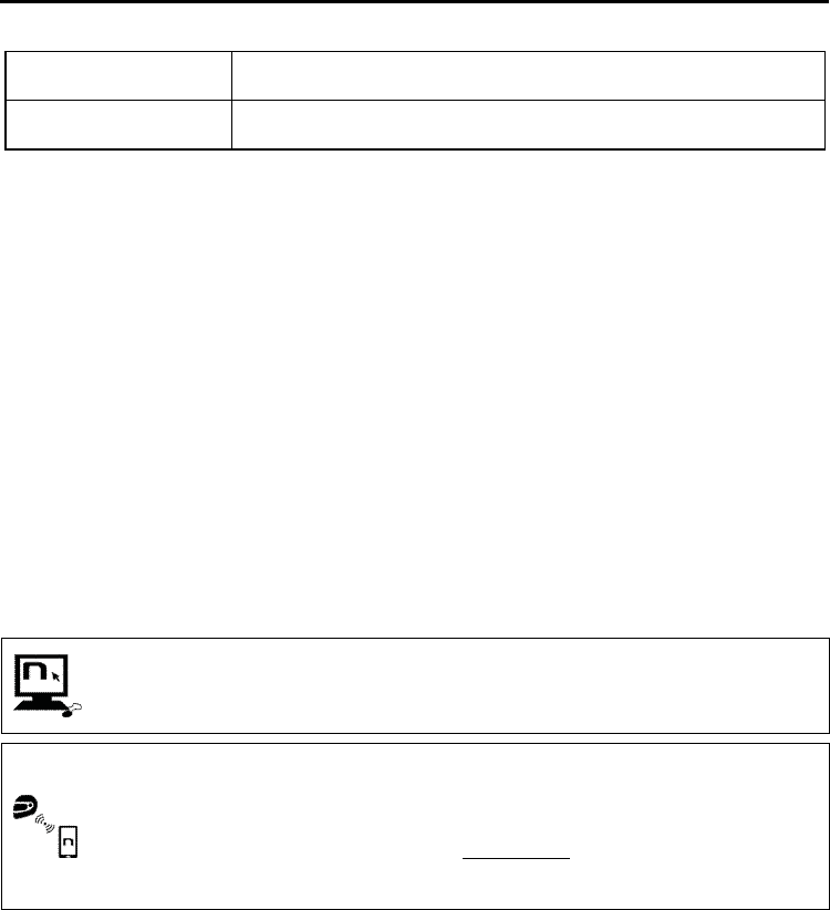
3.1. Preparing the ESS system
Fig. 2
Select the specific adapter for your helmet
(the compatible helmet model is shown on
the back of the support).
N.B.: The installation of the ESS system on N87
and N105 helmets requires no adapter.
Remove the protective film from the double-
sided adhesive tape located in the rear of the
system ESS (Fig. 2)
Fig. 3
Apply the double-sided adhesive tape
supplied as standard equipment to the
selected plastic adaptor (Fig. 3).
Fig. 4
Insert the FLEX cable of the ESS system in the
hole of the selected adapter as illustrated, in
the direction shown in the image (Fig. 4);
Fig. 5
Rotate the adapter until it is in a horizontal
position like the ESS system, then press the
two components together until they stick
one onto the other (Fig. 5);
B901L
9
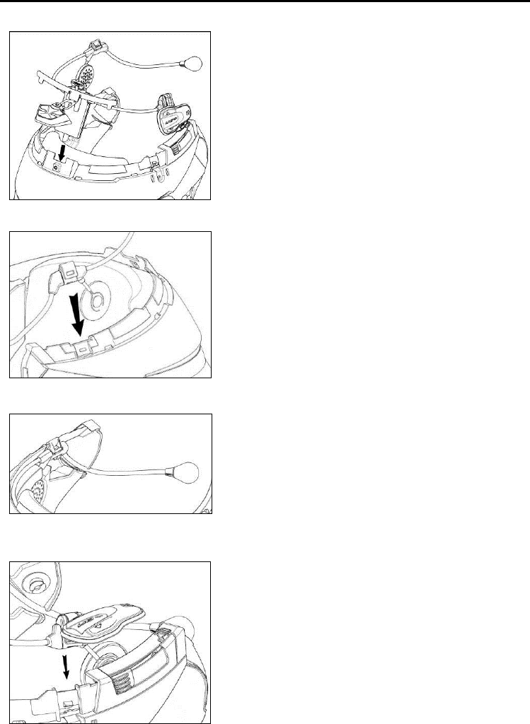
3.2. Installing the ESS system on the helmet
Fig. 6
Place the system in the special housing in the
back of the helmet, pushing it all the way
into the groove (Fig. 6).
Important: Make sure the Flex cable is not
pulled too tightly.
Fold the antenna back inside the shell.
Fig. 7
N.B.: For positioning of the wiring and of the
microphone in the N105 helmet, follow the
instructions provided in the dedicated box.
Fix the cable inside the helmet and make
sure the right fixing clip snaps into its
housing (Fig. 7)
Fig. 8
Position the microphone in the housing on
the left of the helmet, inserting the metal
boom in the groove found in the chin guard
coupling frame (Fig. 8).
Caution: make sure that the side of the
microphone support with the writing “N-
Com” is facing inward.
Fig. 9
Fix the cable inside the helmet and make
sure the left fixing clip snaps into its housing.
Hook up the keypad to the helmet by
clicking in the relevant hooks.
N.B.: For positioning of the keypad in helmets
N87 and N105, follow the instructions provided in
the dedicated box.
Open the rubber cap of the B901L system.
Reassemble the gasket and secure it with the
specific screw.

EN
10
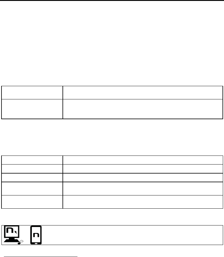
ONLY FOR HELMET N105 – positioning of wiring and microphone
Positioning the right side wiring and the microphone:
Lift up the plastic lining of the cheek padding (Fig. 10)
Insert the microphone into the eyelet (Fig. XX) and position it in the special housing, then
inserting the metal boom in the groove found in the chin guard coupling frame (Fig. XX)
Caution: make sure that the side of the microphone support with the writing “N-Com” is facing
inward.
Fix the cable inside the helmet and make sure the right fixing clip snaps into its housing (Fig.
XX)
Reposition the plastic lining of the cheek padding, arranging it behind the two small stop hooks
(Fig. XX)
Positioning the left side wiring:
Lift up the plastic lining of the cheek padding (Fig. XX)
Fix the cable inside the helmet and make sure the left fixing clip snaps into its housing (Fig. XX)
Reposition the plastic lining of the cheek padding, arranging it behind the two small stop hooks
(Fig. XX)
Fig. Fig.
B901L
11
FOR N87
–
N105
HELMENT
S
ONLY
–
positioning the keypad
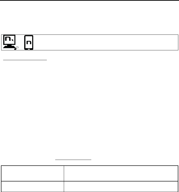
Important: Installation of the keypad on the N87, N105 helmets requires the use of the “KEYPAD
ADAPTER” accessory, which is included in the package.
Insert the support specific for your helmet in the flex cable of the keypad (Fig. XX);
Rotate the keypad support so as to position it like in Fig. XX, then hook it to the keypad;
Fix the cable inside the helmet and make sure the left fixing clip snaps into its housing (Fig. XX);
Open the rubber cap of the B901L system.
Reassemble the gasket and secure it with the specific screw;
Hook up the keypad to the helmet by clicking in the relevant hooks (Fig. XX);
The proper positioning of the keypad is illustrated in Fig. XX and in Fig. XX.
Fig. 10
Fig. 11
Fig. 12
Fig. 13
Fig. 14
Fig. 15
EN
12
Position the left and right speakers in the respective housing obtained in the polystyrene cheek
padding. If necessary, rotate the speakers slightly in their housing.
Reassemble the cheek padding.
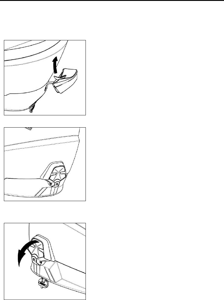
3.3. Positioning the ESS system on the helmet
Fig. 16
Remove the protective film from the
double-sided adhesive tape of the helmet
adapter (Fig. 16) and apply the ESS system
to the shell (Fig. 17).
Attention: Position the “N” of the ESS
system at the shell edge gasket screw, so
that the adapter is lined up with the
helmet lines.
Fig. 17
Remove the clear protective film from the
ESS system.
Reassemble the cheek padding.
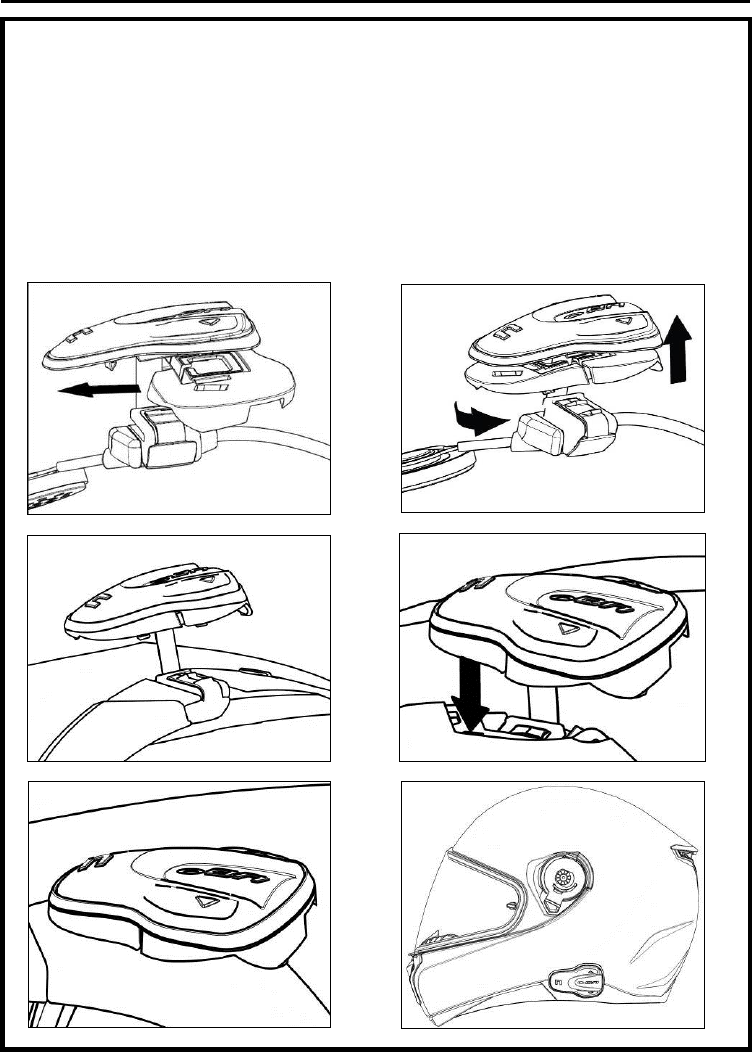
3.4. Removing the B901L system from the helmet
Fig. 18
Proceed as follows to remove the B901L system
from the helmet:
Remove the ESS light from the shell (Fig.
18).
B901L
13
Fig. 19
Remove the cheek padding and the shell
gasket;
Remove the keypad from the shell, as
shown in fig. 19.
FOR
N87
–
N105
HELMENT
S
ONLY
–
removing the keypad
Remove the keypad from the shell, as indicated in fig. 20.
Rotate the keypad in a counterclockwise direction (Fig. 21)
Remove the cheek padding and the shell gasket.
Fig. 20
Fig. 21
Fig. 22
Unhook the right and left clips from the
shell, levering upward using a flat head
screw (or a similar tool), as shown in figure
22.
Fig. 23
Completely remove the B901L system
from helmet using a flat head screwdriver
(or similar tool) and re-install the cheek
padding and the edge gasket.
EN
14
4. BASIC FUNCTIONS
System ON Press “ON” and keep it pressed for about 2 seconds, until the LEDs turn
on and you hear the voice announcement.
System OFF Press “ON” and keep it pressed for about 6 seconds, until the LEDs turn
off and you hear the voice announcement.
N.B.: during the switch on/switch off phase of the B901L system, the ESS light flashes for a few
seconds.
4.1. Volume adjustment
You can easily adjust the volume by tapping the “” button or the “” button. You will hear a beep
when the volume reaches the maximum or minimum level.
The volume is independent for each sound source. Once it is set for a specific source (phone call,
radio, Mp3), it will be remain in memory even after the system is switched off.
However, if you adjust the volume during stand-by mode, it will affect volume levels of every audio
source.
4.2. Auto On / Off function
If the helmet does no move for more than 60 seconds, the B901L system goes into “deep sleep”
mode. The system is completely turned on as soon as movement is detected.
If the system is in “deep sleep” mode for more than 3 days, it turns off completely. To turn it back on,
the “ON” key need to be pressed.
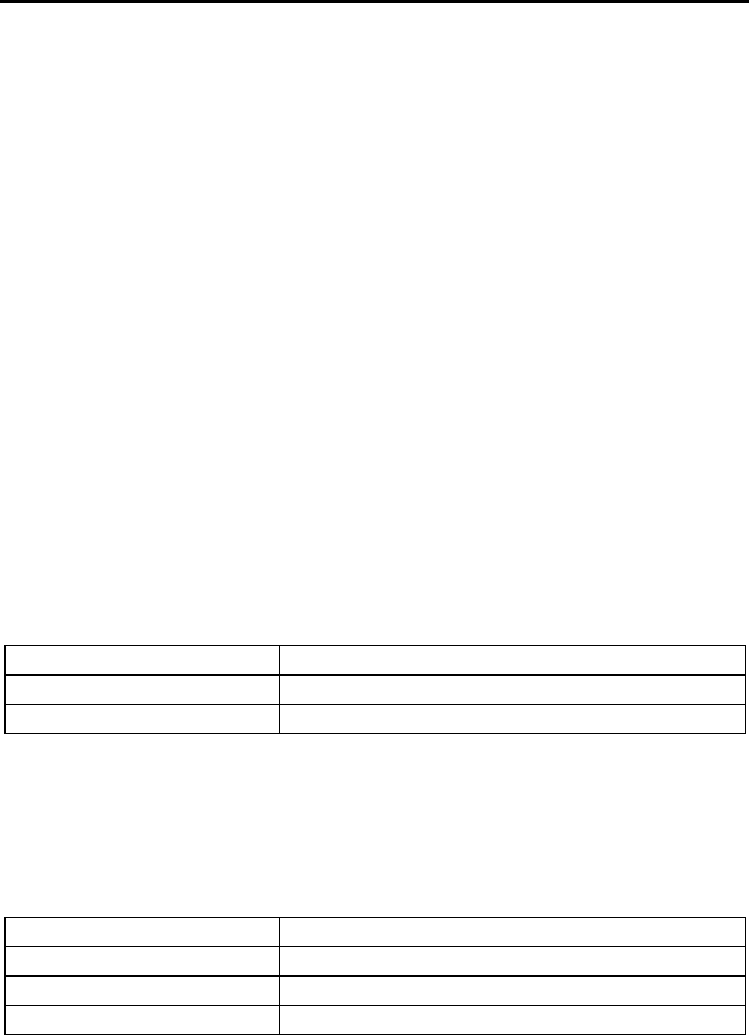
4.3. N-Com EASYSET
“N-Com EASYSET” is the application that can be used to manage and configure the B901L
system. The programme can be downloaded from the Internet site www.n-com.it, in the
“Download” section. The functions that can also be managed from the N-Com EASYSET
are listed here below with the specific icon.
The N-Com system can be managed from the dedicated App “N-Com EASYSET”, which
makes it possible to configure and control the N-Com system directly from your
Smartphone.
The N-Com APP can be downloaded free of charge from Google Play or Apple Store.
For additional details, please visit the website www.n-com.it
The functions that can also be managed from the N-Com EASYSET App are listed here
below with the specific icon.

B901L
15
5. CONFIGURATION MENU
All Bluetooth pair ups and other adjustments are carried out in this mode.
To put the system in “Configuration mode” (starting from a switched off system) press the “ON” key
and keep it pressed for 4 seconds, until the blue LED starts flashing quickly and you hear the voice
announcement “
Configuration
”.
Once in the “Configuration” menu, press the keys“” and “” to scroll through the various menu
items.
In the items marked with an “*”, it is possible to enable / disable the function or carry out the
commands by pressing the “ON” key to confirm.
The following items make up the “Configuration” menu:
A. Mobile phone pair up (chapter 6)
B. Intercom pair up (chapter 14)
C. Universal Intercom pair up (chapter 15)
D. Second mobile phone pair up (chapter 8)
E. Remote control pair up (chapter 16)
F. Speed dialling* (chapter 7.1)
G. Audio boost *
By enabling the “Audio boost” (Audio Boost), all the audio sources inside the device will be
reproduced at a higher and potentially less clear volume.
Press the “ON” confirmation key to enable / disable the function, which is not enabled by
default on the device.
H. ESS sensitivity* (chapter 13.1)
I. Delete all pair ups*
In order to delete all Bluetooth pair ups stored in the device, press the key “” or “” until
you hear the voice announcement “
Delete all pair ups
””.
Press the “ON” confirmation key to delete all Bluetooth devices stored in memory.
J. Reset*
In order to restore the factory settings of the device, press the key “” or “” until you hear
the voice message “
Reset
”.
Press the “ON” confirmation key to restore all the factory settings of the device.
K. Exiting the configuration*
To exit the “Configuration” menu, press the key “” or “” until you hear the voice
announcement “
Exit the configuration menu
”.
Press the “ON” confirmation key to exit the “Configuration” menu.
If no key is pressed within 10 seconds, the device automatically exits the “Configuration” menu.
EN
16
6. PAIRING UP WITH MOBILE PHONES OR OTHER BLUETOOTH DEVICES
•Make sure the B901L is turned off;
•Put the system in the “Configuration” mode, then press the “ON” key and keep it pressed
for 4 seconds until the blue LED starts flashing quickly;
•Press the key “” to access the “Mobile phone pair up mode””.
•Turn on the search for Bluetooth devices (smartphone, MP3 reader) on the device;
•Select the N-Com device. If a password is requested, enter 0000 (four zeros);
•Connection between the two devices is established after a few seconds.
Note: The affiliation is stored in the helmet and in the cell phone and it is not lost when the two
devices are turned off. As a result it needs to be carried out only once.
Automatic Connection Once the Bluetooth device has been paired up, connection is automatic
when the system is turned on.
Manual Connection
In case connection is not automatically initiated after a few seconds, you
can connect from the Bluetooth device or by pressing “ON” and keep it
pressed for about 2 seconds.
7. MOBILE PHONE
To pair up a mobile phone to the B901L system, follow the procedure illustrated in Chapter 6.
Answering a phone call Briefly press any key when you hear the incoming call signal.
Vocal answer When you hear the ringtone, say any word out loud.
Voice call Press “ON” and keep it pressed for about 2 seconds.
Hanging up/rejecting a
phone call Press “ON” and keep it pressed for about 2 seconds.
Manual phone
connection Press “ON” and keep it pressed for about 2 seconds.
7.1. Speed dialling
Using the N-Com EASYSET program or the N-Com EASYSET App, you can store
up to 3 of your favourite numbers, which you will be able to dial from the
“Speed Dialling” menu.
Saving the Speed Dialling numbers
To assign one or more speed dialling numbers:
Put the system in the “Configuration” mode: starting from a switched off system, press the “ON”
key and keep it pressed for 4 seconds, until the blue LED starts flashing quickly and you hear the
voice announcement “Configuration”.
Press the key “” or “” until you hear the voice command “
Speed dialling
”.
Press the “ON” confirmation key. You will hear the voice announcements “
Speed dialling 1
” and
“Phone connected”
.
Press the keys “” or “” to select the speed dialling number to be assigned. The saved position
is confirmed by the voice announcement
“Speed dialling 1
/ “
Speed dialling 2”
/
“Speed dialling 3”
.
B901L
17
On your own mobile phone (paired up and connected to the N-Com system), call the phone
number you wish to assign to the selected speed dialling position. The call is interrupted before it
goes through, and the selected number will be saved; at this point you will hear the special voice
announcement confirming the selection (“
Save Speed Dialling 1” /
“
Save Speed Dialling 2/
“
Save
Speed Dialling 3”
).
You can also configure these setting through the program “N-Com EASYSET” or
through an Android Smartphone, iPhone, iPad on which the “N-Com EASYSET”
App has been installed.
Using the stored numbers
To access the “Speed Dialling” menu, press at the same time the “ON” and “N” keys (“
Speed Dialling”)
,
then use the keys “” and “” to scroll through the menu items.
Then press the “ON” key to confirm the selection of one of the following items:
Call Last Number Dialled
Speed Dialling 1
Speed Dialling 2
Speed Dialling 3
Cancel
If you wish to exit the “Speed Dialling” menu, press the keys “” and “” until you hear the
command “
Cancel
”, then press “ON” to confirm.
N.B.: If no key is pressed within 15 seconds, the system exits the “Speed Dialling” menu.
7.2. Conference call function
When a call comes in on a mobile phone connected via Bluetooth to B901L, the intercom is
temporarily turned off. However, if you wish to share the phone call with the other helmet, simply
turn on the intercom manually during the phone call.
Turning on the phone conference
call function
During the phone call, briefly press “N” (channel 1).
During the phone call, press the “N” key twice (channel 2).
During the phone call, press the “N” key three times (channel 3).
Turning off the phone conference
call function During the phone call, briefly press “N”.
EN
18
8. MANAGING TWO MOBILE PHONES (OR BLUETOOTH DEVICES)
The B901L system can be hooked up to two phones (or Bluetooth) devices at the same time.
The second phone (secondary device) can receive calls but not make them.
To pair up the second Bluetooth phone (secondary device):
•Make sure the B901L is turned off;
•Put the system in the “Configuration” menu: press the “ON” key and keep it pressed for 4
seconds, until the blue LED starts flashing quickly;
•Press the pushbutton “” until you reach the option “
Pair up second mobile phone
”.
•Turn on the search for Bluetooth devices (smartphone, MP3 reader) on the device;
•Select the N-Com system from the list. If a password is requested, enter the code 0000
(four zeroes);
•After a few seconds, the connection between the two devices is activated.
Once the Bluetooth device has been paired up, connection is automatic when the system is turned
on.
9. MUSIC VIA BLUETOOTH
To pair up an Mp3 device to the B901L system, follow the procedure illustrated in Chapter 6.
Play music (Play) Briefly press “ON”.
Pause function (Pause) When the player is connected and playing music, briefly press
“ON”.
Next track (Skip) When the player is playing music, press “” for 2 about seconds.
Previous track (Rew) When the player is playing music, press “” for 2 about seconds.
9.1. Sharing music via Bluetooth (
A2DP Sharing
)
During the intercom connection, you can start playing music by briefly pressing the “ON” key. The
music will be played in both systems.
Music sharing temporarily cuts off the intercom conversation; however, this can be automatically
restored by stopping the music (this is done by briefly pressing the “ON” key).
N.B.: Music shared through the intercom can be managed by both systems, for example, both
systems can change the track by pressing the relative command.
B901L
19
10. MUSIC VIA CABLE
Connect the mini USB connector of the Multimedia Wire (not included) to the helmet and the other
end to the audio device. A coloured band on the cable indicates the connector to be hooked up to
the audio device.
Turning on the cable audio Press the “ON” key three times.
Turning off the cable audio Press the “ON” key three times.
11. SATELLITE NAVIGATOR FOR MOTORCYCLES
B901L system is compatible with the most common satellite navigators for motorcycles. For a list of
compatible models and additional details, visit the website www.n-com.it
To pair up a satellite navigator to the B901L system, follow the procedure illustrated in Chapter 6.
N.B.: Intercom connection is automatically cut off every time the navigator gives directions and
restored at the end of the message from the navigator.
EN
20
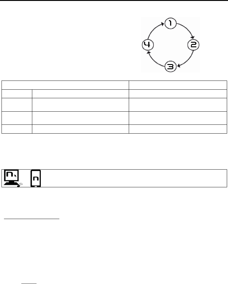
13. LED SIGNALLING LIGHTS
The B901L system features a menu with 3 operating
modes: EMERGENCY STOP SIGNAL, REAR LIGHT,
POOR VISIBILITY LIGHT.
To scroll through this menu, with the system turned
on, press keys “” and “” and keep them pressed
for about 2 seconds. Every time you press the key,
the system switches to the next mode.
MODE FUNCTIONS
1 EMERGENCY STOP SIGNAL Emergency stop signal.
2 REAR LIGHT Emergency stop signal.
Stable rear light.
3 POOR VISIBILITY LIGHT Emergency stop signal.
Intermittent light in case of poor visibility.
4 SWITCH OFF Complete switch off of LED lights
13.1. Emergency Stop Signal ESS (mode 1)
The B901L system is equipped with a LED system to assist emergency braking. In case of sudden
braking, the LEDs on the B901L flash for a few seconds.
The braking level can be adjusted using the “N-Com EASYSET” programme or
through the “N-Com EASYSET App” for Smartphone Android, iPhone, iPad.
N.B.: We recommend turning off the Emergency Stop Signal on the Rider’s helmet in case a Pillion
Passenger is riding on the back.
ESS sensitivity adjustment
Put the system in the “Configuration” mode: from a switched off system, press the “ON” key and keep
it pressed for 4 seconds, until the blue LED starts flashing and you hear the voice announcement
“
Configuration
”.
To adjust the sensitivity of the ESS lamp, press the key “” or “” until you hear the voice
announcement “
ESS sensitivity
”, then press the “ON” confirming.
Afterwards, press the key “” or “” to select the desired sensitivity level:
Level 1: low sensitivity, the ESS system will only detect significant braking.
Level 2 (default): average sensitivity.
Level 3: high sensitivity, the ESS system will also detect slight braking.
13.2. Rear Light (mode 2)
The tail light makes it possible to activate the LEDs of the system, keeping them on during the entire
ride.
If the emergency brake light is activated during braking, all LEDs will start flashing.
B901L
21
13.3. Poor visibility light (mode 3)
The poor visibility light allows you to be more visible in case of fog or limited visibility. If selected, the
LEDs of the system will flash intermittently.
If the emergency brake light is activated during braking, all LEDS will flash more quickly.
14. N-COM INTERCOM (SERIES “900”)
The N-Com B901L system allows communication with other N-Com systems, up to a distance of
about 700 m (in open field, with no obstacles).
Important: The procedure described below refers exclusively to the pairing up and operation between
the B901L and the “900” series N-Com systems.
To pair up to N-Com systems of a range other than the “900” series, please refer to the procedure
described in chapter 15 “Universal Intercom”.
N.B.: The range and quality of the communication may vary significantly depending on the presence
of obstacles, weather conditions, magnetic fields.
N.B.: The range of the communication varies depending on the N-Com systems used.
14.1. Intercom pairing up
Make sure the B901L is turned off;
Put the systems in “Configuration” mode: press the “ON” key and keep it pressed for 4
seconds, until the blue LED starts flashing;
On both systems, press the key “” until you reach the option “
Intercom pair up
”;
On system A, press the key pertaining to the “pre-setting position” where you wish to save
system B.
Pairing up CHANNEL 1 Briefly press “N”.
Pairing up CHANNEL 2 Press the “N” key twice.
Pairing up CHANNEL 3 Press the “N” key three times.
The Intercom connection with the selected channel is automatically activated at the end of the pair up
procedure.
14.2. Intercom function (one-to-one connection)
To establish an Intercom connection with one of the systems stored in memory, simply press the
command related to the channel where the system was saved.
Connection CHANNEL 1 Briefly press “N”.
Call CHANNEL 2 Press the “N” key twice.
Call CHANNEL 3 Press the “N” key three times.
Disconnection of active intercom Briefly press “N”.
EN
22
The B901L system is equipped with the VOX function, which makes it possible to switch the intercom
on and off vocally. Once the intercom is manually activated for the first time, the B6L system detects
your voice and automatically activates/deactivates the communication.
You can enable / disable the “VOX” function and set the activation sensitivity,
using the N-Com EASYSET program or the N-Com EASYSET APP.
The VOX function is disabled by default on the device.
N.B.: In case the pre-setting position is empty, or the system being called cannot be reached within
the maximum range or it is already engaged in a phone call, you will hear an error voice message.
N.B.: In case the Intercom connection system falls outside the range (Intercom connection
interrupted), the B901L system will automatically try to reconnect every 8 seconds. Double beeps
will be emitted until the Intercom connection is not restored.
If you do not want automatic reconnection, press the “ON” key to stop the automatic reconnection
attempts.
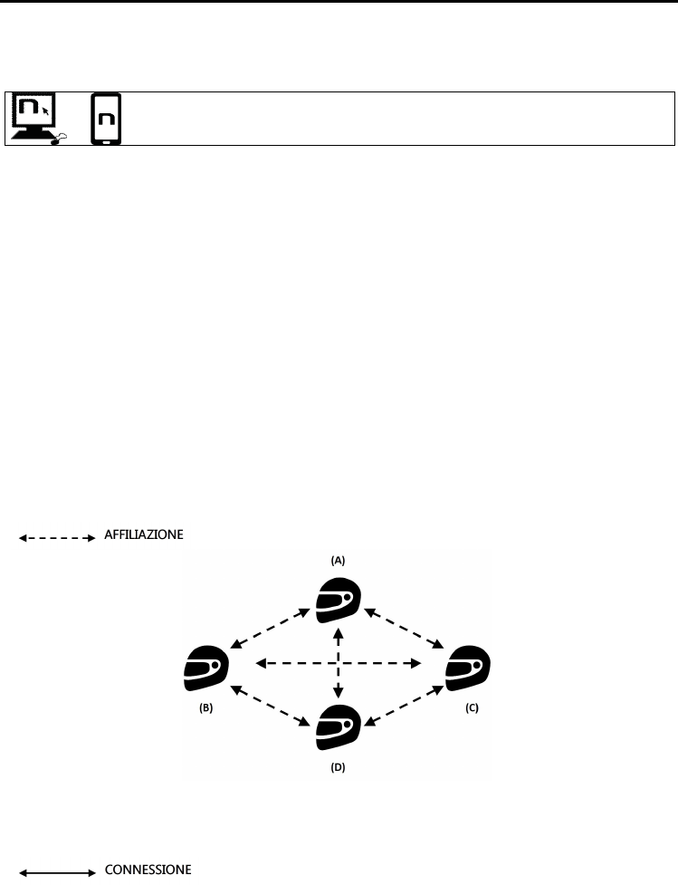
14.3.
Smart Conference
(Group Intercom)
Thanks to the “Smart Conference” function, you can start the conference communication between N-
Com intercom systems of the “900” series previously paired up and saved in the 3 available channels.
All systems must be turned on and available within the connection range.
1. Each system must have been previously paired up to all the other systems: B, C and D.
2. Any system can press the “N” key for 2 seconds to activate the Group Conference or to start
a conference communication between all the systems.
B901L
23
3. In the case where one of the systems presses the “N” key or falls outside the connection
range, the group intercom is interrupted.
Smart Conference connection
Press the “N” key for 2 seconds. Activation is confirmed by a
beep in the helmet and by the voice message “
Group
Intercom”
.
Smart Conference disconnection Briefly press the “N” key. Disconnection is confirmed by the
voice announcement “
Group Intercom ended
.
N.B.: During a “Smart Conference” call, connection to the mobile phones of all participants is
temporarily cut off. When the conference call ends, all phones automatically reconnect to their own
intercom system.
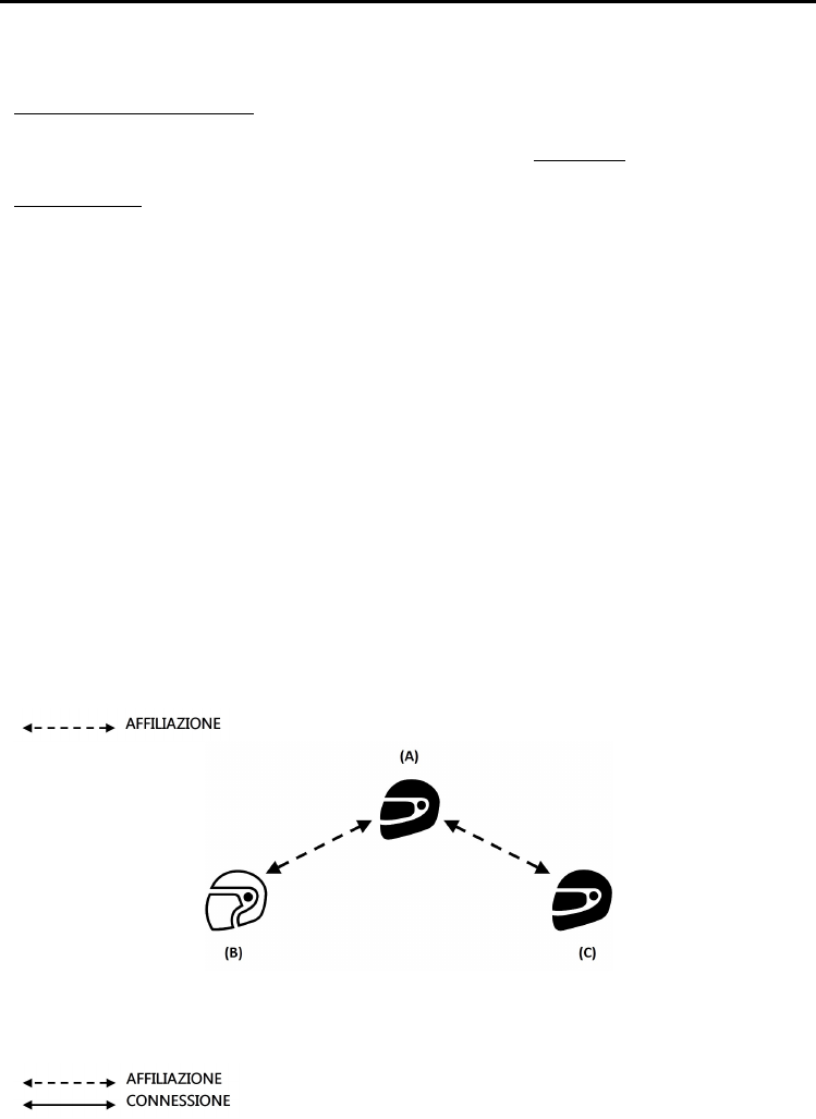
15. “UNIVERSAL INTERCOM” INTERCOM
The N-Com B901L system can be connected via Bluetooth to intercom systems of other brands or to
N-Com systems other than the “900” series, thanks to the UNIVERSAL INTERCOM function.
Important: N-Com systems other than the “900” series must be paired up to the N-Com B901L by
following the procedure “
Pairing up the Universal Intercom
”.
Caution: Visit the www.n-com.it website for the list of compatible N-Com systems.
15.1. Pairing up the UNIVERSAL INTERCOM
The N-Com system can be paired up to the other intercom (from now on referred to as Intercom B)
as if it was a mobile phone.
1. Make sure the B901L is turned off;
2. Put the system in the “Configuration” mode: press the “ON” key and keep it pressed for 4
seconds, until the blue LED starts flashing;
3. Press the pushbutton “” until you reach the option “
Universal intercom pair up
” mode.
4. Put intercom B in the mobile phone pairing up mode (refer to the Intercom B manual);
5. After a few seconds, Intercom B will emit the “phone connection” confirmation beep;
N.B.: The system paired up using the UNIVERSAL INTERCOM is saved in the first available channel.
EN
24
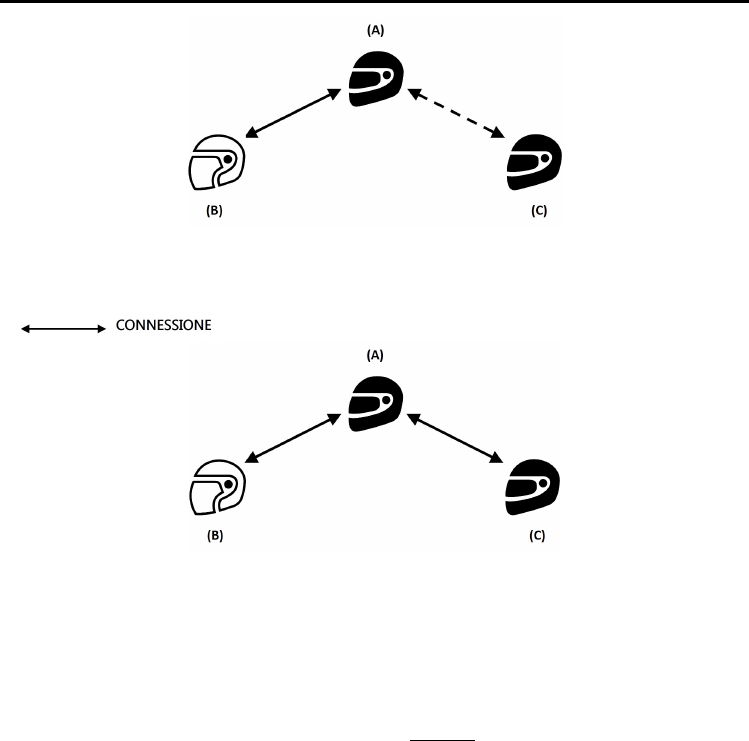
15.2. Universal Intercom Function
To turn on and off the audio between two helmets, proceed as follows:
From the N-Com B901L system:
Connect or disconnect Intercom B as you would for a regular N-Com intercom (chapter 14).
Intercom B may receive a dialing one that must be answered with a phone reply command.
From intercom B
Press the “
Voice call / Dial last number called
” command.
To disconnect the intercom, press “
Voice call / Dial last number called
” once again.
N.B.:
•The N-Com B901L systems keeps an active connection with a mobile phone even during
Bluetooth communication with other intercom systems.
•The intercom system connected to N-Com B901L may not allow simultaneous connection to a
mobile phone.
•Only one system paired up in Universal Intercom mode can be stored.
15.3. Universal Conference (chain intercom)
The “Universal Conference” mode can be used to connect in conference call N-Com systems of the
“900” series and one system paired up in Universal Intercom mode.
N.B.: This mode can also be used by connecting only N-Com “900” series systems, in alternative to the
“Smart Conference” mode (chapter 14.3).
The connection procedure is outlined in the diagram provided here below:
1. System A must have been paired up beforehand to two B systems (Universal Intercom pair
up) and C.
2. System A has to initiate the first intercom connection with system B (Universal Intercom), by
pressing the relative intercom connection command.
B901L
25
3. At this point, system C can join the intercom conference call, establishing an intercom
connection with system A.
4. The three systems are not in intercom conference call mode and can talk to each other at
the same time. All intercom conference call systems can be disconnected by briefly pressing
the “N” command on any one of the devices connected in conference call.
5. In case you wish to add another system (D), the latter must be paired up beforehand to
system C. Press the relative connection command to start a 4-participant intercom
conference call.
N.B.: The “
Universal Conference
” mode (chapter 14.3) CANNOT be used with systems paired up in
Universal Intercom mode.
EN
26
16. REMOTE CONTROL
The B901L device can be controlled through a remote control (sold separately), thus avoiding the
need to take your hands off the handlebars to use the keyboard.
Please refer to the specific operating instructions of the Remote Control in order to use its various
functions.
17. BATTERY AND RECHARGE
17.1. Low battery signal
During its operation, the system alerts the user with a voice message when the battery is low. From
the first message, the system has a 1-hour autonomy. Warning is given every 10 minute.
17.2. Charging the system
To charge the system, hook it up to the
battery charger or to a USB outlet powered
with the USB-mini USB cable supplied as
standard equipment. The charge will take
place as follows:
B901L
system
turned off
When the B901L system is connected to the battery charger, the blue LED starts to
flash quickly. When the battery is charged, the blue LED becomes steady.
B901L system
turned on
When the B901L system is connected to the battery charger, the blue LED starts to
flash quickly. When the battery is charged, the blue LED goes back to its standard
flashing.
N.B.: If the device has not been charged for a long time (a few months), it may not be possible to turn
on the system during the first few minutes of the charging, as the voltage may drop below the
minimum limit.
B901L
27
18. SUMMARY TABLE OF CONTROLS
Button
N ON
+
Basic Functions
Turning on 2 sec
Turning off 6 sec
Increase Volume X
Decrease Volume X
Management of Lights Menu 2 sec
Bluetooth Devices
Answer phone call* X X X X
Voice call 2 sec
Speed Dialling Menu** X X
Hang up/reject a phone call 2 sec
Manual Device Connection 2 sec
Phone Conference Activation
CHANNEL 1 X
Phone Conference Activation
CHANNEL 2 x2
Phone Conference Activation
CHANNEL 3 x3
Turning off the Conference
function X
Bluetooth Music / Cable
Play music (Play) X
Pause Function (Pause) X
Next track (Forward) 2 sec
Previous track (REW) 2 sec
Share A2DP music X
Activate audio via cable x3
Deactivate audio via cable x3
EN
28
Button
N ON
+
N-Com Intercom (900
series)
Connection CHANNEL 1 X
Disconnection of active
intercom X
Calling CHANNEL 2 x2
Calling CHANNEL 3 x3
Group intercom connection 2 sec
Group intercom disconnection X
Radio Menu
Turning on the Radio x2
Turning off the Radio x2
Automatic search for new
station 2 sec
Change station
(pre-set stations) 2 sec
Pre-set station 4 sec
Setting***
Pairing up mode (system turned
off) 4 sec
Pairing up secondary mobile
phone (or device) 2 sec
Pairing up CHANNEL 1 (“900”
series) X
Pairing up CHANNEL 2 (“900”
series) x2
Pairing up CHANNEL 3 (“900”
series) x3
Reset 4 sec
*Press any key on the N-Com keypad.
**Press the keys at the same time.
***All the Setting functions must be carried with the system in Setting Mode.

B901L
29
19. LIMITED WARRANTY
With this LIMITED WARRANTY CERTIFICATE, Nolangroup warrants this Product to be free from defects in material
and workmanship at the time of its original purchase by the buyer.
We invite you to:
- Read the cautions pertaining to safety and proper use.
- Read the warranty terms and conditions.
- Keep the originals sales receipt. This must be shown in case of repairs covered by warranty. In these cases, the
product has to be taken back to the dealer where it was purchased.
19.1. Warranty coverage
If any defect covered by this limited warranty certificate is discovered within 2 (two) years from the purchase date
shown on the tax receipt, Nolangroup shall repair or replace the defective product through its distribution network
after having verified the defect. Nolangroup shall supply all the material and labor that is reasonably required to
remedy the defect, except in those cases where the damage is caused by one of the items listed in the following
paragraph “Exclusions and limitations of the Coverage”.
19.2. Exclusions and limitations of the coverage
This warranty only covers defects in materials and manufacturing. Nolangroup shall not be considered responsible
for product defects that can be attributed, either partially or in full, to any other cause, including but not limited to:
Defects or damages resulting from using the Product in conditions that differ from the usual ones.
Damages caused by improper use not conforming with normal operation in accordance with the product
operating and maintenance instructions provided by Nolangroup.
Negligence and normal wear of internal and external parts.
Any damage caused by an accident;
Any change or modification made to the helmet or to the N-Com system by the user or by third parties.
Colour changes or damages caused by exposure to harmful chemical products.
The use of incompatible accessories that are not part of the N-Com product range.
Moreover, the warranty does not cover product defects caused by fortuitous events, modifications or
adjustments, causes of force majeur or damages deriving from the product coming in contact with liquids.
The internal helmet components are not and cannot be waterproof. Consequently, any improper exposure to
rain, humidity, food spillages or other liquids can result in damages to the N-Com electronic devices, damages
for which Nolan shall not be responsible.
This warranty does not include those parts subject to wear and tear such as, for example, the rechargeable
battery and the cables used for connection between the various N-Com systems or between the N-Com systems
and other devices.
Since Nolangroup does not supply the system on which the cell phones work, it shall not be responsible for the
operation, availability, coverage, services or range pertaining to the aforementioned system.
Whenever the product is used in conjunction with accessories or equipment not supplied by Nolangroup,
Nolangroup shall not guarantee proper operation of the product/device combination, nor will it accept requests
for repairs or replacements under warranty in case the product is used in such a way.
Nolangroup shall not be responsible in case the product presents limited capabilities due to the operating mode of
cell phones or of other accessories or equipment not supplied by Nolangroup.
Tampering with the internal electronic card or with other parts of the N-Com system shall invalidate the warranty.
Moreover, the defects covered by this warranty do not include all those specific and subjective situations that may
come up during the active use of the helmet such as, for example, comfort problems while riding or aerodynamic
noises.
Nolangroup shall not be held responsible in any case for incidental or consequential damages (including, without
any limitation whatsoever, damages to one or more persons) resulting from non-fulfilment of the obligations arising
from this warranty as it pertains to Nolangroup products.

EN
30
19.3. Validity of this limited warranty
This warranty is valid only if the enclosed warranty form is duly and completely filled out with the following
information:
Product identification code
Name and stamp of the authorized dealer.
Product purchase date.
Buyer’s name and address.
Nolangroup reserves itself the right to not carry out repairs under warranty if the aforementioned information is
removed or modified after the original purchase of the product from the dealer.
19.4. Procedure for the forwarding of claims
To forward a claim covered by this warranty, the buyer has to directly notify the dealer where the helmet was
purchased with regards to the defect, presenting at the same time the defective product, a copy of the sales receipt
and the Warranty registration form, duly filled out as instructed above.
PRIOR TO CONTACTING THE DEALER, WE RECOMMEND THAT YOU READ CAREFULLY THE USER MANUAL
ENCLOSED WITH THE PRODUCT.
AFTER 2 (TWO) YEARS FROM THE DATE OF PURCHASE, THIS LIMITED WARRANTY IS VOID FOR ALL EFFECTS AND
PURPOSES.
Repairs or maintenance under warranty do not extend the period of the warranty itself. Therefore, in case the
product or one of its components is replaced, this does not initiate a new warranty period, as the purchase date of
the original product shall be taken into account for warranty purposes.
Only for repairs or replacement of electronic components, in the event that Nolangroup proceeds to repairing or
replacing the product, said product shall enjoy a warranty period equal to the residual portion of the original
warranty or ninety (90) days from the repair date (the longer period being considered).
The repair or replacement can be carried out even with regenerated components with equivalent functions.
The replaced parts or components shall become property of Nolangroup.
THIS WARRANTY VOIDS AND REPLACES ANY OTHER WRITTEN OR VERBAL WARRANTIES PROVIDED FOR BY THE
LAW THAT CAN BE DEROGATED AT THE PARTIES’ WILL; SPECIFICALLY, NOLANGROUP DOES NOT GRANT SPECIFIC
WARRANTS OF MERCHANTABILITY OR FITNESS FOR A PARTICULAR PURPOSE. IN NO CASE SHALL NOLANGROUP
BE LIABLE FOR INCIDENTAL OR CONSEQUENTIAL DAMAGES INCLUDING BUT NOT LIMITED TO LOST PROFITS OR
COMMERCIAL DAMAGES, TO THE FULL EXTENT THOSE DAMAGES CAN BE DISCLAIMED BY THE LAW.
NOLANGROUP RESERVES ITSELF THE RIGHT TO MODIFY, AT ANY TIME AND WITHOUT ADVANCE NOTICE, THE
PRODUCT CHARACTERISTICS, FUNCTIONS, COMPATIBILITY AND SOFTWARE.
Some Countries do not allow the exclusion or limitation of incidental or consequential damages, or the limitation of
the duration of implied warranties; as a result of this, the previous limitations and exclusions may not be applicable
to you.
This warranty does not have any effect on the customer’s legal rights under the national jurisdiction in force or on
the consumer’s rights towards the dealer sanctioned by the purchase/sale contract.
This warranty is valid throughout the European territory, and it represents the only express warranty provided by
Nolangroup in relation to the sale of its own products. This warranty does not affect the rights to which the buyer is
entitled and which are expressly provided for by Directive 1999/44/CE.
This warranty does not affect the consumer’s rights provided for by the law, and specifically by the provisions of
Legislative Decree 2 February 2002 n. 24.
19.5. Product identification
N-Com products are identified by means of a code that allows product traceability
and identification.
The identification code is listed on the adhesive label applied to the B901L system
and on the outside of the sales package.
20. WARRANTY REGISTRATION FORM
Product name
B9
01
L
Identification code
Buyer’s Information
Name
Last name
Address
Phone
e
-
mail
Dealer’s stamp
Date of purchase

Certification and Safety Approvals
FCC Compliance Statement
This device complies with part 15 of the FCC rules.
Operation is subject to the following two conditions:
(1) This device may not cause harmful interference, and
(2) This device must accept any interference received, including interference that
may cause undesired operation.
This equipment has been tested and found to comply with the limits for a Class B
digital device pursuant to part 15 of the FCC rules. These limits are designed to
provide reasonable protection against harmful interference in a residential
installation. This equipment generates, uses and can radiate radio frequency energy
and, if not installed and used in accordance with the instructions, may cause harmful
interference to radio communications. However, there is no guarantee that
interference will not occur in a particular installation. If this equipment does cause
harmful interference to radio or television reception, which can be determined by
turning the equipment on and off, the user is encouraged to try to correct the
interference by one or more of the following measures:
•Reorient or relocate the receiving antennae
•Increase the separation between the equipment and the receiver
•Connect the equipment into an outlet on a circuit different from that to which the
receiver is connected.
•Consult the dealer or an experienced radio/TV technician for help.
FCC RF Exposure Statement
This equipment complies with FCC radiation exposure limits set forth for an
uncontrolled environment. End users must follow the specific operating instructions
for satisfying RF exposure compliance. The antenna used for this transmitter must
not transmit simultaneously with any other antenna or transmitter, except in
accordance with FCC multi-transmitter product procedures.
FCC Caution
Any changes or modifications to the equipment not expressly approved by the party
responsible for compliance could void user’s authority to operate the equipment.
Certification et homologation de sécurité
Déclaration de conformité FCC
Cet appareil est en conformité avec la partie 15 des règles de
la FCC. Son fonctionnement est soumis aux deux conditions suivantes :
(1) Cet appareil ne doit pas créer d’interférences préjudiciables et
(2) Cet appareil doit accepter toutes les interférences reçues, y compris celles qui
pourraient entraver son bon fonctionnement. Cet équipement a été testé et jugé
conforme aux limites pour
un appareil numérique de classe B, conformément à la partie 15 des règles de la
FCC. Ces limites sont conçues pour fournir une protection raisonnable contre les
interférences nuisibles dans une installation résidentielle. Cet équipement génère et
utilise de l’énergie radio fréquence et, s’il n’est pas installé et utilisé conformément

aux instructions, il peut occasionner des interférences nuisibles au niveau des
communications radios. Cependant, il n’existe aucune garantie que ces
interférences ne se produiront pas dans une installation particulière. Si cet
équipement génère des interférences nuisibles à la réception de la radio ou de la
télévision (ce qu’il est possible de déterminer en mettant l’équipement hors tension,
puis sous tension), l’utilisateur est invité à suivre une ou plusieurs des mesures
suivantes pour corriger le problème des interférences en prenant l’une des mesures
suivantes :
•Modifier l’emplacement ou l’orientation de l’antenne de réception.
•É loigner l’appareil du récepteur.
•Brancher l’appareil sur une prise située sur un circuit différent de celui du
récepteur.
•Consulter le revendeur ou un technicien expérimenté pour obtenir de l’aide.
É noncé FCC sur l’exposition aux radiations RF
Cet équipement est conforme aux réglementations FCC d’exposition aux radiations
définies pour un environnement non contrôlé. Les utilisateurs doivent respecter les
instructions d’exploitation spécifiques pour répondre aux exigences de conformité
sur l’exposition aux RF. L’antenne utilisée pour cet appareil ne doit pas fonctionner
en même temps qu’une autre antenne ou émetteur, sauf s’il y a conformité avec les
procédures FCC des produits multi-émetteurs.
Précautions FCC
Tout changement ou modification non expressément approuvé par la partie
chargée de la mise en conformité peut annuler le droit de l’utilisateur à utiliser
l’équipement.
Industry Canada Statement
This device complies with Industry Canada license-exempt RSS standard(s).
Operation is subject to the following two conditions:
(1) This device may not cause interference.
(2) This device must accept any interference, including interference that may cause
undesired operation of the device.
Déclaration de conformité IC (Industrie Canada)
Le présent appareil est conforme aux CNR d'Industrie Canada applicables aux
appareils radio exempts de licence. L'exploitation est autorisée aux deux conditions
suivantes :
(1) Cet appareil ne doit pas créer d'interférences.
(2) Cet appareil doit accepter toutes les interférences reçues, y compris celles qui
pourraient entraver son bon fonctionnement.