Nonin Medical SABER SABER User Manual Model 3150 WristOx2 Pulse Oximeter
Nonin Medical, Inc. SABER Model 3150 WristOx2 Pulse Oximeter
UserManual.wiki
>
Nonin Medical
>
SABER User Manual
>
User Manual
Contents
1.
Users Manual Info
2.
Users Manual Additional Info
3.
User Manual
User Manual
Navigation menu
Upload a User Manual
Namespaces
Wiki Guide
HTML
PDF
Info
Views
User Manual
Discussion / Help
Navigation
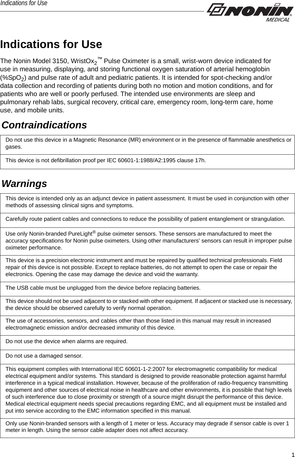
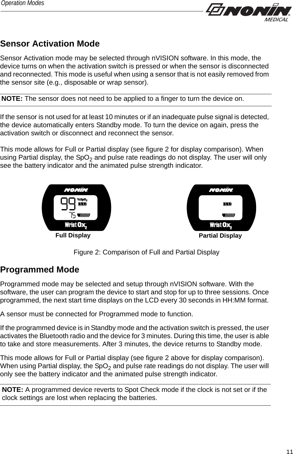
![10Operation ModesOperation ModesThe WristOx2, Model 3150, has three states: Cable, Standby, and On.Cable The device is in Cable mode when it is connected to a PC using the USB interface cable. While in Cable mode, the device does not collect or save data and the Bluetooth radio is off. Standby When the device is in Standby mode, the screen is blank and the device appears to be off. In Standby, it is ready for a signal that will turn the device on (e.g., pressing activation switch, inserting finger in sensor [Spot Check mode], connecting sensor [Sensor Activation mode], or programmed start time [Programmed mode]). While in Standby mode, the device does not collect or save data and the Bluetooth radio is off. OnWhen the device is on, it can collect and save data. The device features three turn on modes: • Spot Check mode• Sensor Activation mode• Programmed modeThe device is delivered in Spot Check mode. nVISION software (version 6.3 or higher) is needed to access the device settings and change Spot Check mode to Sensor Activation or Programmed mode (see “nVISION Software”).The device recalls the active settings when the device is shut off and turned on again. Spot Check ModeSpot Check mode is the default turn on operation mode. The device automatically turns on when a finger is inserted into the sensor. It enters Standby mode 10 seconds after the finger is removed. If the sensor is disconnected, the device enters Standby mode immediately. In this mode, the sensor can be left connected to the device.NOTE: If the device determines that a sensor fault exists (a sensor failure, misalignment, or incompatibility with the device) or if a pulse oximeter sensor signal cannot be detected, the device enters Standby mode after 3 minutes.](https://usermanual.wiki/Nonin-Medical/SABER.User-Manual/User-Guide-1328200-Page-15.png)
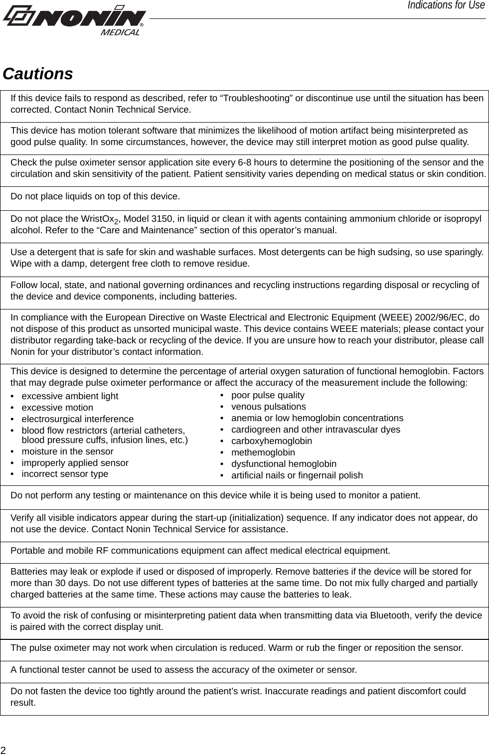
![27TroubleshootingIf these solutions do not correct the problem, please contact Nonin Technical Service at (800) 356-8874 (USA and Canada) or + 1 (763) 553-9968.No pulse display on pulse strength indicator (continued).Sensor applied to polished or artificial nail. Remove fingernail polish or an artificial nail.Sensor Light-Emitting Diode (LED) is not lit. Contact Nonin Technical Service. Er 01 displays on LCD. Device configuration memory failure. Device reverts to default settings (Spot-Check mode, 4-second sample rate). Use nVISION software to change settings. If error code continues, contact Nonin Technical Service. Er 02 or 04 displays on LCD. Device memory failure. Contact Nonin Technical Service. Er 03 or 05 displays on LCD. Device failure. Device memory intact, but device may have lost most recent session or stored data.If error code continues, contact Nonin Technical Service. Dashes continually display on LCD. Sensor malfunction. Replace sensor with a Nonin-branded sensor. Device does not record in Programmed mode.Data collection start and stop times are set incorrectly. Use nVISION software to program correct start and stop times.Clock settings are lost after replacing batteries. Use nVISION software to reset clock.Devices will not pair. Device is out of range. Verify device is in range while being paired (approximately 100 meters [328 feet] spherical radius).Bluetooth radio has timed out. Press activation switch to turn on Bluetooth radio.Problem Possible Cause Possible Solution](https://usermanual.wiki/Nonin-Medical/SABER.User-Manual/User-Guide-1328200-Page-32.png)