Nonin Medical SABER SABER User Manual Model 3150 WristOx2 Pulse Oximeter
Nonin Medical, Inc. SABER Model 3150 WristOx2 Pulse Oximeter
Contents
- 1. Users Manual Info
- 2. Users Manual Additional Info
- 3. User Manual
User Manual

Operator’s Manual
Model 3150
WristOx2
™ Pulse Oximeter
Wrist-Worn Pulse Oximeter
with Bluetooth
®
Wireless Technology
English
0123
CAUTION: Federal law (USA) restricts this device to sale by or on the order of a
licensed practitioner.
Nonin® reserves the right to make changes and improvements to this manual and the products it
describes at any time, without notice or obligation.
Nonin Medical, Inc.
13700 1st Avenue North
Plymouth, MN 55441-5443
USA
+ 1 (763) 553-9968
800-356-8874 (USA and Canada)
Fax: + 1 (763) 553-7807
e-mail: mail@nonin.com
www.nonin.com
0123
EC
REP
MPS, Medical Product Service GmbH
Borngasse 20
D-35619 Braunfels, Germany
References to “Nonin” in this manual imply Nonin Medical, Inc.
Nonin, WristOx2, PureLight, and nVISION are registered trademarks or trademarks of Nonin
Medical, Inc. The Bluetooth word mark and logo are owned by the Bluetooth SIG, Inc. and any use
of such marks by Nonin Medical, Inc. is under license. Other trademarks and trade names are
those of their respective owners.
© 2010 Nonin Medical, Inc.
7622-001-01
Consult Instructions for Use.

i
Contents
Indications for Use.................................................................................................... 1
Contraindications.................................................................................................... 1
Warnings ................................................................................................................ 1
Cautions ................................................................................................................. 2
Declaration of Conformity with FCC and Canadian Ministry
of Health Rules for Electromagnetic Compatibility .............................................. 3
Federal Communications Commission (FCC) Notice............................................. 3
Guide to Symbols...................................................................................................... 4
Displays, Controls, and Indicators.......................................................................... 5
Introduction ............................................................................................................... 8
Unpacking the WristOx2, Model 3150 .................................................................... 8
Standard Kit ....................................................................................................... 8
Starter Kit .......................................................................................................... 8
Batteries ................................................................................................................ 9
Bluetooth Technology............................................................................................ 9
Operation Modes..................................................................................................... 10
Cable ................................................................................................................... 10
Standby .............................................................................................................. 10
On........................................................................................................................ 10
Spot Check Mode ............................................................................................ 10
Sensor Activation Mode................................................................................... 11
Programmed Mode .......................................................................................... 11
Using the WristOx2, Model 3150 ............................................................................ 12
Installing Batteries ............................................................................................... 12
Wrist Straps......................................................................................................... 13
Ring Strap Description..................................................................................... 13
Attach Ring Strap to Device............................................................................. 14
Adjustable Strap Description............................................................................ 15
Attach Adjustable Strap to Device ................................................................... 15
Attaching the Sensor ........................................................................................... 18
Patient Application............................................................................................... 19
Two-Piece Wrist Band Application................................................................... 19
Single Strap Application................................................................................... 21
Verifying Operation.............................................................................................. 24
Startup Sequence and Self-Test....................................................................... 24
Activation Switch ................................................................................................. 25
Activate Bluetooth Radio.................................................................................. 25
Activate Device ................................................................................................ 25
Error Codes ......................................................................................................... 25
Troubleshooting..................................................................................................... 26
Care and Maintenance ............................................................................................ 28
Cleaning the Device ............................................................................................ 28
Cleaning the Sensor............................................................................................ 28
Cleaning the Wrist Band...................................................................................... 28
Storing ................................................................................................................. 28

ii
Contents (Continued)
Memory and Data.....................................................................................................29
nVISION Software ....................................................................................................30
nVISION Settings................................................................................................. 30
Accessing nVISION Settings ............................................................................ 30
Cable Connection................................................................................................. 31
USB Driver Installation (XP) ............................................................................. 32
USB Driver Installation (Vista) .......................................................................... 32
USB Driver Installation (Windows 7)................................................................. 33
Bluetooth Connection........................................................................................... 33
Parts and Accessories ........................................................................................... 35
Service, Support, and Warranty ............................................................................ 36
Service and Support............................................................................................. 36
Warranty............................................................................................................... 36
Technical Information............................................................................................. 37
Manufacturer’s Declaration ................................................................................ 37
Equipment Response Time................................................................................ 40
Testing Summary............................................................................................... 41
SpO2 Accuracy Testing .................................................................................. 41
Pulse Rate Motion Testing.............................................................................. 41
Low Perfusion Testing .................................................................................... 41
Specifications..................................................................................................... 42
Oximeter Specifications.................................................................................. 42
System Specifications..................................................................................... 43
Transmitter ..................................................................................................... 44

iii
Figures
Figure 1. Front Display (Startup Screen).............................................................. 5
Figure 2. Comparison of Full and Partial Display................................................ 11
Figure 3. Remove Battery Door.......................................................................... 12
Figure 4. Insert Batteries.................................................................................... 12
Figure 5. Ring Strap ........................................................................................... 13
Figure 6. Thread Ring Strap............................................................................... 14
Figure 7. Attach Ring Strap................................................................................ 14
Figure 8. Adjustable Strap.................................................................................. 15
Figure 9. Thread Adjustable Wrist Strap ............................................................ 16
Figure 10. Attach Adjustable Wrist Strap ........................................................... 16
Figure 11. Device with Wrist Straps Attached (Front and Back Views).............. 17
Figure 12. Attach Sensor.................................................................................... 18
Figure 13. Verify Two-Piece Wrist Band Attachment ......................................... 19
Figure 14. Thread and Tighten Two-Piece Wrist Band ...................................... 20
Figure 15. Fasten Two-Piece Wrist Band........................................................... 20
Figure 16. Apply Sensor to Patient .................................................................... 21
Figure 17. Verify Single Strap Attachment ......................................................... 21
Figure 18. Thread Single Strap ......................................................................... 22
Figure 19. Tighten Single Strap.......................................................................... 22
Figure 20. Fasten Single Strap........................................................................... 23
Figure 21. Apply Sensor to Patient..................................................................... 23
Figure 22. nVISION Settings Window ................................................................. 31
Tables
Table 1. Labeling Symbols.................................................................................. 4
Table 2. Error Codes......................................................................................... 25
Table 3. Electromagnetic Emissions ................................................................. 37
Table 4. Electromagnetic Immunity................................................................... 38
Table 5. Guidance and Manufacturer’s Declaration—
Electromagnetic Immunity ................................................................ 39
Table 6. Recommended Separation Distances................................................. 40

1
Indications for Use
Indications for Use
The Nonin Model 3150, WristOx2™ Pulse Oximeter is a small, wrist-worn device indicated for
use in measuring, displaying, and storing functional oxygen saturation of arterial hemoglobin
(%SpO2) and pulse rate of adult and pediatric patients. It is intended for spot-checking and/or
data collection and recording of patients during both no motion and motion conditions, and for
patients who are well or poorly perfused. The intended use environments are sleep and
pulmonary rehab labs, surgical recovery, critical care, emergency room, long-term care, home
use, and mobile units.
Contraindications
Do not use this device in a Magnetic Resonance (MR) environment or in the presence of flammable anesthetics or
gases.
This device is not defibrillation proof per IEC 60601-1:1988/A2:1995 clause 17h.
Warnings
This device is intended only as an adjunct device in patient assessment. It must be used in conjunction with other
methods of assessing clinical signs and symptoms.
Carefully route patient cables and connections to reduce the possibility of patient entanglement or strangulation.
Use only Nonin-branded PureLight® pulse oximeter sensors. These sensors are manufactured to meet the
accuracy specifications for Nonin pulse oximeters. Using other manufacturers’ sensors can result in improper pulse
oximeter performance.
This device is a precision electronic instrument and must be repaired by qualified technical professionals. Field
repair of this device is not possible. Except to replace batteries, do not attempt to open the case or repair the
electronics. Opening the case may damage the device and void the warranty.
The USB cable must be unplugged from the device before replacing batteries.
This device should not be used adjacent to or stacked with other equipment. If adjacent or stacked use is necessary,
the device should be observed carefully to verify normal operation.
The use of accessories, sensors, and cables other than those listed in this manual may result in increased
electromagnetic emission and/or decreased immunity of this device.
Do not use the device when alarms are required.
Do not use a damaged sensor.
This equipment complies with International IEC 60601-1-2:2007 for electromagnetic compatibility for medical
electrical equipment and/or systems. This standard is designed to provide reasonable protection against harmful
interference in a typical medical installation. However, because of the proliferation of radio-frequency transmitting
equipment and other sources of electrical noise in healthcare and other environments, it is possible that high levels
of such interference due to close proximity or strength of a source might disrupt the performance of this device.
Medical electrical equipment needs special precautions regarding EMC, and all equipment must be installed and
put into service according to the EMC information specified in this manual.
Only use Nonin-branded sensors with a length of 1 meter or less. Accuracy may degrade if sensor cable is over 1
meter in length. Using the sensor cable adapter does not affect accuracy.

2
Indications for Use
Cautions
If this device fails to respond as described, refer to “Troubleshooting” or discontinue use until the situation has been
corrected. Contact Nonin Technical Service.
This device has motion tolerant software that minimizes the likelihood of motion artifact being misinterpreted as
good pulse quality. In some circumstances, however, the device may still interpret motion as good pulse quality.
Check the pulse oximeter sensor application site every 6-8 hours to determine the positioning of the sensor and the
circulation and skin sensitivity of the patient. Patient sensitivity varies depending on medical status or skin condition.
Do not place liquids on top of this device.
Do not place the WristOx2, Model 3150, in liquid or clean it with agents containing ammonium chloride or isopropyl
alcohol. Refer to the “Care and Maintenance” section of this operator’s manual.
Use a detergent that is safe for skin and washable surfaces. Most detergents can be high sudsing, so use sparingly.
Wipe with a damp, detergent free cloth to remove residue.
Follow local, state, and national governing ordinances and recycling instructions regarding disposal or recycling of
the device and device components, including batteries.
In compliance with the European Directive on Waste Electrical and Electronic Equipment (WEEE) 2002/96/EC, do
not dispose of this product as unsorted municipal waste. This device contains WEEE materials; please contact your
distributor regarding take-back or recycling of the device. If you are unsure how to reach your distributor, please call
Nonin for your distributor’s contact information.
This device is designed to determine the percentage of arterial oxygen saturation of functional hemoglobin. Factors
that may degrade pulse oximeter performance or affect the accuracy of the measurement include the following:
• excessive ambient light
• excessive motion
• electrosurgical interference
• blood flow restrictors (arterial catheters,
blood pressure cuffs, infusion lines, etc.)
• moisture in the sensor
• improperly applied sensor
• incorrect sensor type
Do not perform any testing or maintenance on this device while it is being used to monitor a patient.
Verify all visible indicators appear during the start-up (initialization) sequence. If any indicator does not appear, do
not use the device. Contact Nonin Technical Service for assistance.
Portable and mobile RF communications equipment can affect medical electrical equipment.
Batteries may leak or explode if used or disposed of improperly. Remove batteries if the device will be stored for
more than 30 days. Do not use different types of batteries at the same time. Do not mix fully charged and partially
charged batteries at the same time. These actions may cause the batteries to leak.
To avoid the risk of confusing or misinterpreting patient data when transmitting data via Bluetooth, verify the device
is paired with the correct display unit.
The pulse oximeter may not work when circulation is reduced. Warm or rub the finger or reposition the sensor.
A functional tester cannot be used to assess the accuracy of the oximeter or sensor.
Do not fasten the device too tightly around the patient’s wrist. Inaccurate readings and patient discomfort could
result.
• poor pulse quality
• venous pulsations
• anemia or low hemoglobin concentrations
• cardiogreen and other intravascular dyes
• carboxyhemoglobin
• methemoglobin
• dysfunctional hemoglobin
• artificial nails or fingernail polish

3
Indications for Use
Declaration of Conformity with FCC and Canadian Ministry of
Health Rules for Electromagnetic Compatibility
• Nonin Medical, Inc., of 13700 1st Avenue North, Plymouth, Minnesota, 55441, declares
under its sole responsibility that Model 3150, WristOx2 Pulse Oximeter, to which this
declaration relates, complies with part 15 of the FCC Rules. Operation is subject to the
following two conditions: (1) this device may not cause harmful interference, and (2) this
device must accept any interference received, including interference that may cause
undesired operation.
• Ministry of Health (Canada), Safety Code 6: standards include a substantial safety
margin designed to ensure the safety of all persons, regardless of age and health. The
exposure standard for wireless mobile phones employs a unit of measurement known
as the Specific Absorption Rate, or SAR. The SAR limit set by the FCC is 1.6 W/kg.
Federal Communications Commission (FCC) Notice
This device has been tested and found to comply with the limits for a class B digital device,
pursuant to part 15 of the FCC Rules. These limits are designed to provide reasonable
protection against harmful interference in a residential installation. This device generates,
uses, and can radiate radio frequency energy. If not installed and used in accordance with
the instructions, it may cause harmful interference to radio or television reception, which
can be determined by turning the device off and on. The user is encouraged to try to correct
the interference by one or more of the following measures:
• Reorient or relocate the receiving antenna.
• Increase the distance between the device and the receiver.
• Connect the device to an outlet on a circuit different from the outlet where the receiver
is connected
• Consult the dealer or an experienced radio/TV technician for assistance.
• RF Exposure: For body worn operation, to maintain compliance with FCC RF exposure
guidelines, use only accessories that contain no metallic components. Use of other
accessories may violate FCC RF exposure guidelines and should be avoided.
• The WristOx2, Model 3150, is designed and manufactured not to exceed the emission
limits for exposure to radio frequency (RF) energy set by the United States FCC. These
limits are part of comprehensive guidelines and establish permitted levels of RF energy
for the general population. The guidelines are based on the safety standards previously
set by both U.S. and international standards bodies. This device has been shown to be
compliant for localized specific absorption rate (SAR) for uncontrolled environment/
general population exposure limits specified in ANSI/IEEE Std. C95.1-2005.
• The FCC requires the user to be notified that any changes or modifications to this device
that are not expressly approved by Nonin Medical, Inc. may void the user’s authority to
operate the device.
4
Guide to Symbols
Guide to Symbols
This chapter describes the symbols that are found in this manual and on the WristOx2,
Model 3150. Detailed information about display symbols can be found in “Displays,
Controls, and Indicators.”
Symbol Description
!
EC
REP
0123
®
Table 1: Labeling Symbols
Caution!
Consult Instructions for Use.
Authorized Representative in the European Community.
CE Marking indicating conformance to EC directive No. 93/42/EEC
concerning medical devices.
Type BF-Applied Part (patient isolation from electrical shock)
No alarms
Indicates separate collection for electrical and electronic equipment (WEEE).
Continua Certified™ signifies that this product has been tested and proven to
be interoperable with other products that carry the Continua Certified symbol.
Bluetooth® figure mark
Non-ionizing electromagnetic radiation. Equipment includes RF transmitters.
Interference may occur in the vicinity of equipment marked with this symbol.
UL Mark for Canada and the United States with respect to electric shock, fire,
and mechanical hazards only in accordance with UL 60601-1 and
CAN/CSA C22.2 No. 601.1.
IP33 Protected against spraying water and against access to hazardous parts with
a tool, per IEC 60529.
Activation Switch Sensor Port
5
Displays, Controls, and Indicators
Displays, Controls, and Indicators
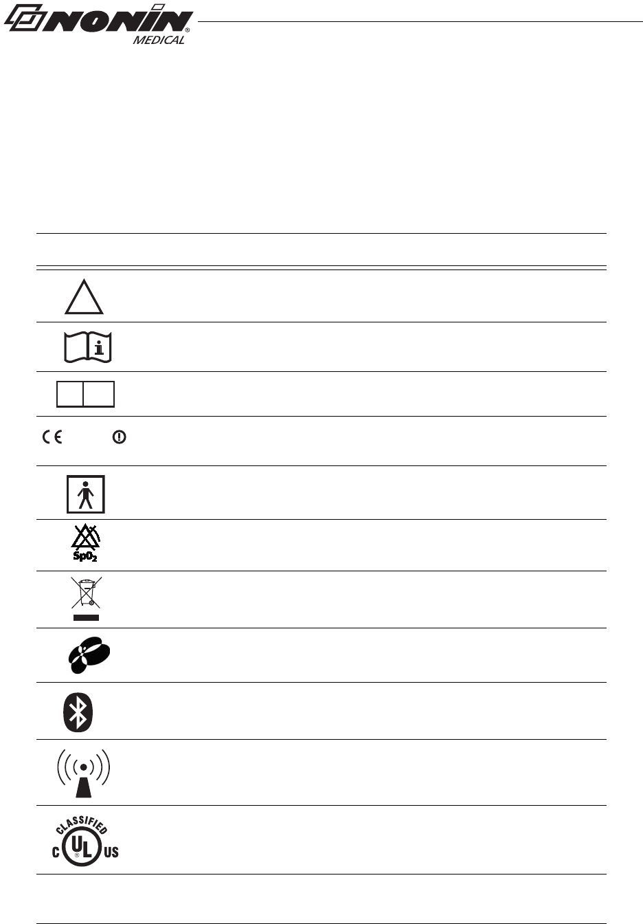
Figure 1: Front Display (Startup Screen)
%SpO2 Display
This 3-digit display, located in the upper left corner of the LCD,
shows percent blood oxygen saturation (%SpO2). The range is
from 0 to 100 %.
This display also shows the month, year, and hour (24-hour clock
format) during startup.
Pulse Rate Display
This 3-digit display, located below the %SpO2 display, shows the
pulse rate in beats per minute (BPM). The range is from 18 to 321
BPM.
This display also shows the day and minute during startup.
Full
Half
Critical
Low
6
Displays, Controls, and Indicators
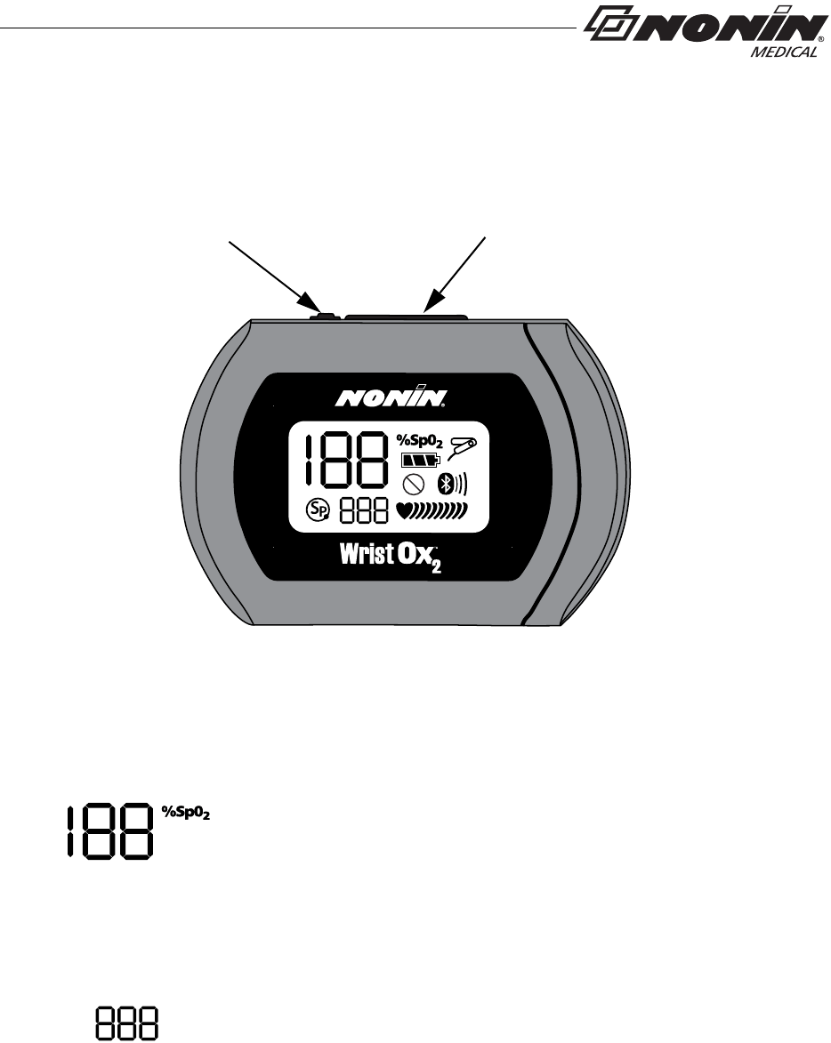
Activation Switch
This switch is located next to the sensor port.
Pressing this switch activates the Bluetooth radio for 3 minutes.
It can also be used to turn the device on when it is in Standby mode.
See “Activation Switch” section for more information.
Sensor Fault Indicator
This indicator displays if the device determines a sensor fault exists
(e.g., sensor disconnect, misalignment, or incompatibility with the
device). It also displays when the finger is removed from the sensor.
Pulse Strength Indicator
This heart-shaped indicator is followed by up to nine curved bars. The
heart shape is always visible, and the number of curved bars on the
display depends on the pulse strength as determined by the oximeter.
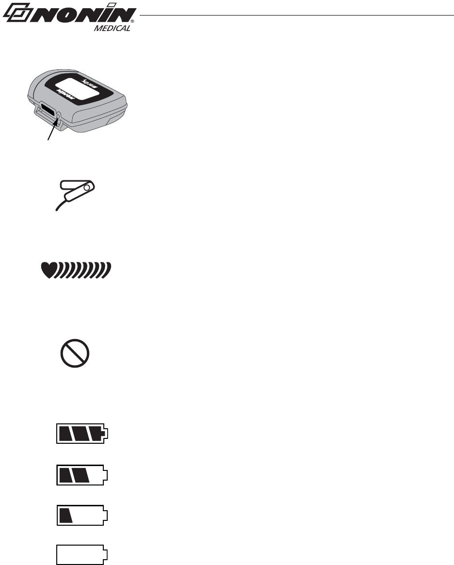
Poor Pulse Signal Indicator
This indicator displays when the pulse signal is inadequate or the
device does not sense a pulse. It may also display if there is
excessive motion at the sensor site.
Battery Indicator
This indicator shows remaining battery life as either full, half, low, and
critical (as shown at left).
Replace the batteries when device reaches low state.
When the battery reaches critical state, all indicators clear from the
display except for the blinking critical battery indicator, the current
session closes, and the Bluetooth radio shuts down.

Bluetooth
indicator
Bluetooth indicator
with animated bars
7
Displays, Controls, and Indicators
Bluetooth Indicator
This indicator displays when the Bluetooth radio is on. It appears as
either the Bluetooth logo or the Bluetooth logo with animated bars.
This indicator displays for the first 2 minutes the device is on. If a
master device does not connect to the device in those 2 minutes, the
Bluetooth radio shuts down and the icon no longer displays.
When the device is connected to a master device, the indicator
displays with animated bars.
If the Bluetooth radio is on when the device enters Standby mode or
connects to the USB interface cable, the Bluetooth indicator appears
on the LCD while the Bluetooth radio shuts down. It will be the only
indicator on the LCD and will display for up to 10 seconds.
SmartPoint Indicator
This indicator displays during the startup sequence.

8
Introduction
Introduction
The Bluetooth-enabled WristOx2, Model 3150, is a small, wrist-worn device that displays,
measures, and stores patient SpO2 and pulse rate data. The device includes a Bluetooth
radio with a range (spherical radius) of approximately 100 meters (328 feet).
The device ships ready to use in Spot Check turn on mode. In Spot Check turn on mode,
inserting a finger in the sensor automatically turns the device on. Approximately 10
seconds after the finger is removed, the device enters Standby mode.
Advanced memory and programming features are available with Nonin’s nVISION®
software (version 6.3 or greater). See the “nVISION Software” section to learn more about
using the device with nVISION.
Unpacking the WristOx2, Model 3150
The WristOx2, Model 3150, standard or starter kit includes the items listed below. Once the
shipping carton is unpacked, verify these items were received. Contact the carrier
immediately if the shipping carton is damaged.
Standard Kit
• Model 3150, WristOx2 Pulse Oximeter
• Model 8000SM-WO2, reusable soft sensor
• 3 two-piece wrist bands, 1 each of the following:
• 6 in. (15 cm)
• 8 in. (20 cm)
• 10 in. (25 cm)
• 2 AAA (1.5 volt) alkaline batteries
• Operator’s manual (CD)
• USB driver software (on operator’s manual CD) – required to use the PC USB interface cable
Starter Kit
A starter kit is required to configure the device and download data to a PC. The starter kit
consists of the standard kit, plus:
• 9 pack of two-piece wrist bands, 3 each of the following:
• 6 in. (15 cm)
• 8 in. (20 cm)
• 10 in. (25 cm)
• nVISION SpO2 data management software (CD)
• PC USB interface cable

9
Introduction
Batteries
The device uses 2 AAA alkaline batteries.
With new alkaline batteries, battery life is approximately 48 hours (minimum) when not
connected to a Bluetooth device. When connected to a Bluetooth device, battery life will
vary depending on class of operation. See “Specifications” for detailed battery life
information.
The battery indicator shows one of four states: full, half, low, and critical. Replace the
batteries when device reaches low state. A low battery has a minimum of 10 minutes
before it reaches critical state. Actual battery life depends on Bluetooth radio use. In critical
battery mode, the battery indicator blinks and the device no longer monitors or records
patient data.
When batteries are removed, the device maintains the time and date for up to 30 seconds.
If replacing batteries takes more than 30 seconds, or if the battery level is at or below the
critical level, clock settings are lost and the device reverts to Spot Check mode. Use
nVISION software to reset the clock and change the operation mode.
Remove the batteries and disconnect the sensor if the device is to be stored for more than
1 month. In storage, battery life is approximately 9 months.
Bluetooth Technology
Bluetooth technology allows wireless connections between electronic communications
and computing devices. The technology is based on a radio link that offers fast and reliable
data transmissions. Bluetooth uses a license-free, globally available frequency range in
the ISM band—intended to ensure communication compatibility worldwide.
Nonin’s use of Bluetooth wireless technology allows SpO2 and pulse rate data to be
transmitted through a Bluetooth radio to a compatible Bluetooth-enabled device. Nonin’s
wireless system removes the cable connection from the device, giving patients increased
ability to move freely.
To make efficient use of battery life, Nonin’s WristOx2, Model 3150, uses an automatically
switchable Class 1/Class 2 Bluetooth radio with a maximum range (spherical radius) of
about 100 meters (328 feet). Obstacles and other conditions may affect range, and class
of operation and connection mode will impact battery life. See “Specifications” for detailed
battery life information.
NOTES:
• This device contains non-volatile memory. Removing or replacing batteries does not
affect the data stored in memory. Stored data remains in memory until overwritten by
newer data or cleared from memory with nVISION software (version 6.3 or greater).
• If batteries are replaced while recording data, the session will terminate and some data
from the session may not be saved. The terminated session will be time stamped with
the current date/time the next time the device turns on.
• If clock settings are lost, the date and time restarts at 01:01:10:00:00.

10
Operation Modes
Operation Modes
The WristOx2, Model 3150, has three states: Cable, Standby, and On.
Cable
The device is in Cable mode when it is connected to a PC using the USB interface cable.
While in Cable mode, the device does not collect or save data and the Bluetooth radio is
off.
Standby
When the device is in Standby mode, the screen is blank and the device appears to be off.
In Standby, it is ready for a signal that will turn the device on (e.g., pressing activation
switch, inserting finger in sensor [Spot Check mode], connecting sensor [Sensor Activation
mode], or programmed start time [Programmed mode]). While in Standby mode, the
device does not collect or save data and the Bluetooth radio is off.
On
When the device is on, it can collect and save data. The device features three turn on
modes:
• Spot Check mode
• Sensor Activation mode
• Programmed mode
The device is delivered in Spot Check mode. nVISION software (version 6.3 or higher) is
needed to access the device settings and change Spot Check mode to Sensor Activation
or Programmed mode (see “nVISION Software”).
The device recalls the active settings when the device is shut off and turned on again.
Spot Check Mode
Spot Check mode is the default turn on operation mode.
The device automatically turns on when a finger is inserted into the sensor. It enters
Standby mode 10 seconds after the finger is removed. If the sensor is disconnected, the
device enters Standby mode immediately.
In this mode, the sensor can be left connected to the device.
NOTE: If the device determines that a sensor fault exists (a sensor failure, misalignment,
or incompatibility with the device) or if a pulse oximeter sensor signal cannot be
detected, the device enters Standby mode after 3 minutes.
11
Operation Modes
Sensor Activation Mode
Sensor Activation mode may be selected through nVISION software. In this mode, the
device turns on when the activation switch is pressed or when the sensor is disconnected
and reconnected. This mode is useful when using a sensor that is not easily removed from
the sensor site (e.g., disposable or wrap sensor).
If the sensor is not used for at least 10 minutes or if an inadequate pulse signal is detected,
the device automatically enters Standby mode. To turn the device on again, press the
activation switch or disconnect and reconnect the sensor.
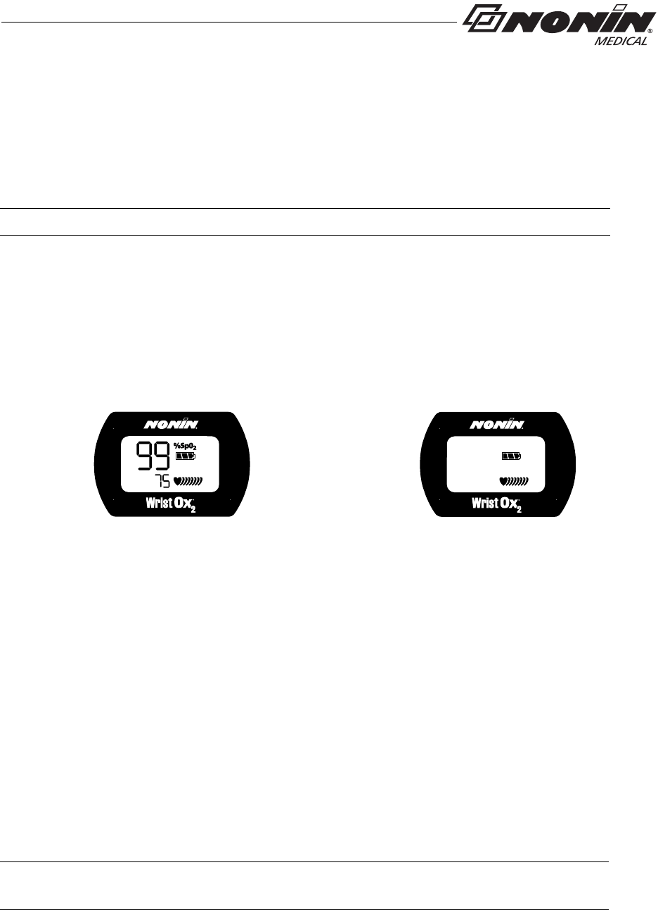
This mode allows for Full or Partial display (see figure 2 for display comparison). When
using Partial display, the SpO2 and pulse rate readings do not display. The user will only
see the battery indicator and the animated pulse strength indicator.
Full Display Partial Display
Figure 2: Comparison of Full and Partial Display
Programmed Mode
Programmed mode may be selected and setup through nVISION software. With the
software, the user can program the device to start and stop for up to three sessions. Once
programmed, the next start time displays on the LCD every 30 seconds in HH:MM format.
A sensor must be connected for Programmed mode to function.
If the programmed device is in Standby mode and the activation switch is pressed, the user
activates the Bluetooth radio and the device for 3 minutes. During this time, the user is able
to take and store measurements. After 3 minutes, the device returns to Standby mode.
This mode allows for Full or Partial display (see figure 2 above for display comparison).
When using Partial display, the SpO2 and pulse rate readings do not display. The user will
only see the battery indicator and the animated pulse strength indicator.
NOTE: The sensor does not need to be applied to a finger to turn the device on.
NOTE: A programmed device reverts to Spot Check mode if the clock is not set or if the
clock settings are lost when replacing the batteries.
12
Using the WristOx2, Model 3150
Using the WristOx2, Model 3150
Installing Batteries
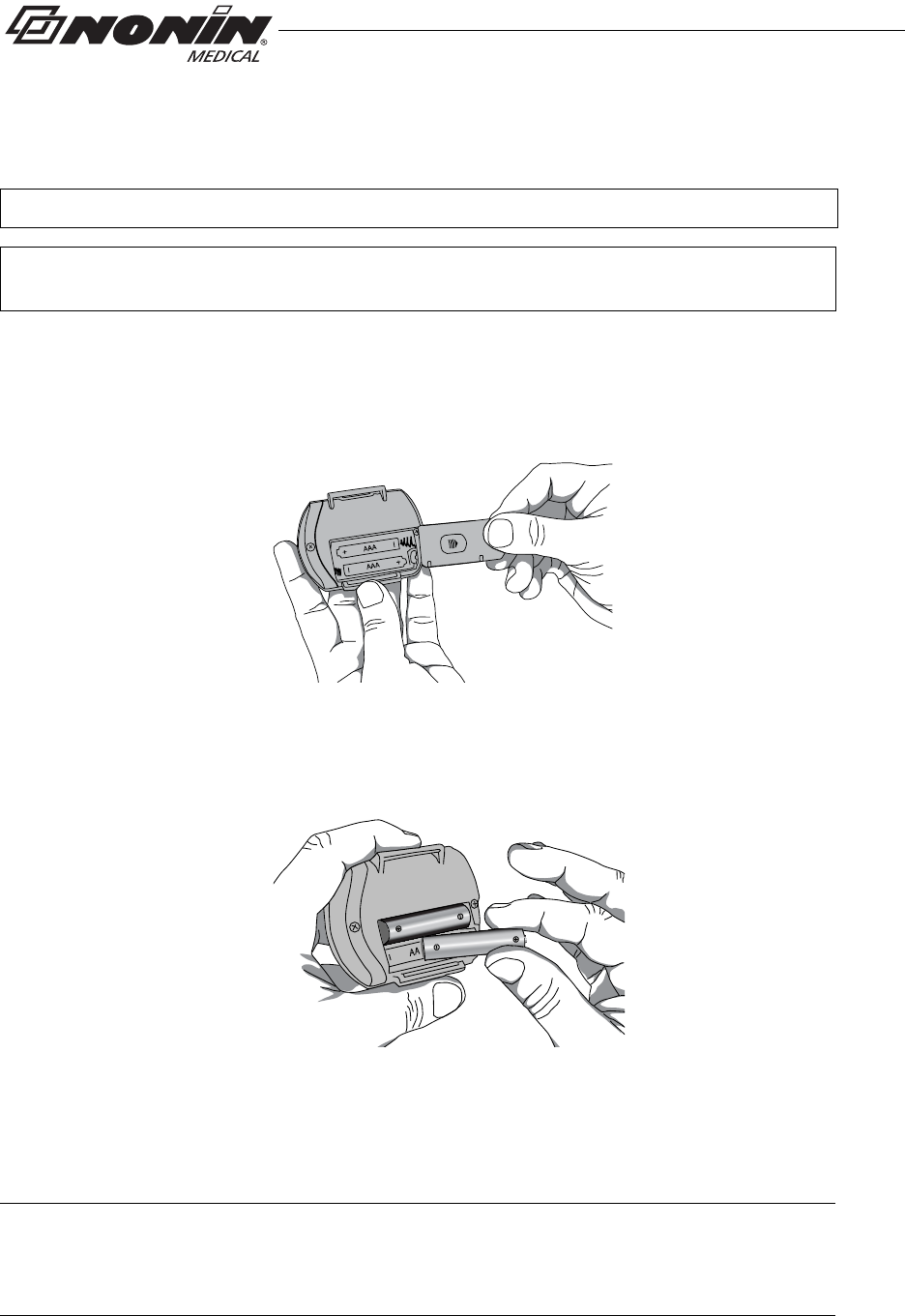
1. Open the battery compartment by sliding the battery door off the back of the
device (figure 3).
Figure 3: Remove Battery Door
2. Insert 2 new AAA alkaline batteries (figure 4). Battery orientation is shown
inside the battery compartment.
Figure 4: Insert Batteries
3. Replace battery door by sliding it back into place.
4. Inserting batteries does not turn the device on. In Spot Check mode, the device
turns on when a finger is inserted in the sensor.
WARNING: Do not use the device when alarms are required.
WARNING: The USB cable must be unplugged from the device before replacing
batteries.
NOTE: When batteries are removed, the device maintains the time and date for up to
30 seconds. If replacing batteries takes more than 30 seconds, or if the battery level is
at or below the critical level, the operation mode reverts to Spot Check mode. Use
nVISION software to reset the clock and change the operation mode.
13
Using the WristOx2, Model 3150
Wrist Straps
The WristOx2, Model 3150, is designed to be applied to the patient’s wrist using a two-
piece wrist band. The two-piece wrist band consists of a ring strap and an adjustable strap.
For pediatrics and petite adults, the device may be applied using a single adjustable strap.
The single adjustable strap is the longer of the two straps in the two-piece wrist band
package.
Straps have hook and loop fasteners on one side. The other side has a smooth, woven
fabric. When the straps are attached to the device, the woven side should touch the
patient’s skin.
This section contains descriptions of the straps and instructions for attaching the straps to
the device. See the “Patient Application” section for instructions on how to apply the device
to the patient.
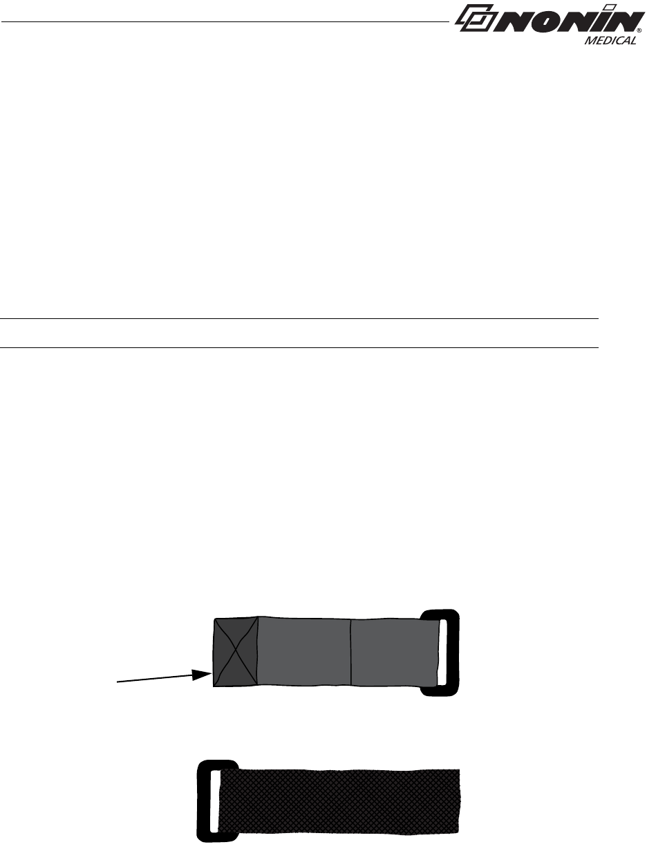
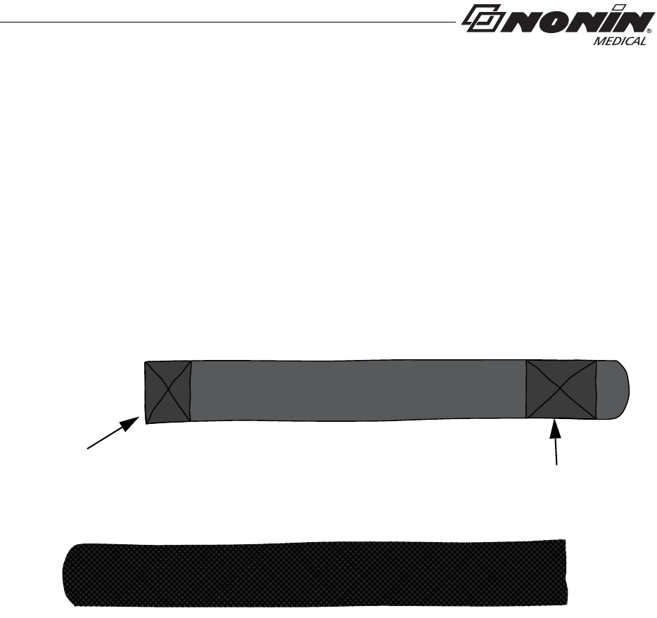
Ring Strap Description
One end of the ring strap has a plastic ring. The square end has a hook and loop fastener
(figure 5).
The square end attaches to the strap bar at the top of the device, by the sensor port
(see “Attach Ring Strap to Device”).
Attach this end to strap
bar by sensor port
Fastener
Hook and Loop Side
Woven Side
Figure 5: Ring Strap
NOTE: A wrist strap has a maximum of 10 uses before replacement is required.
14
Using the WristOx2, Model 3150
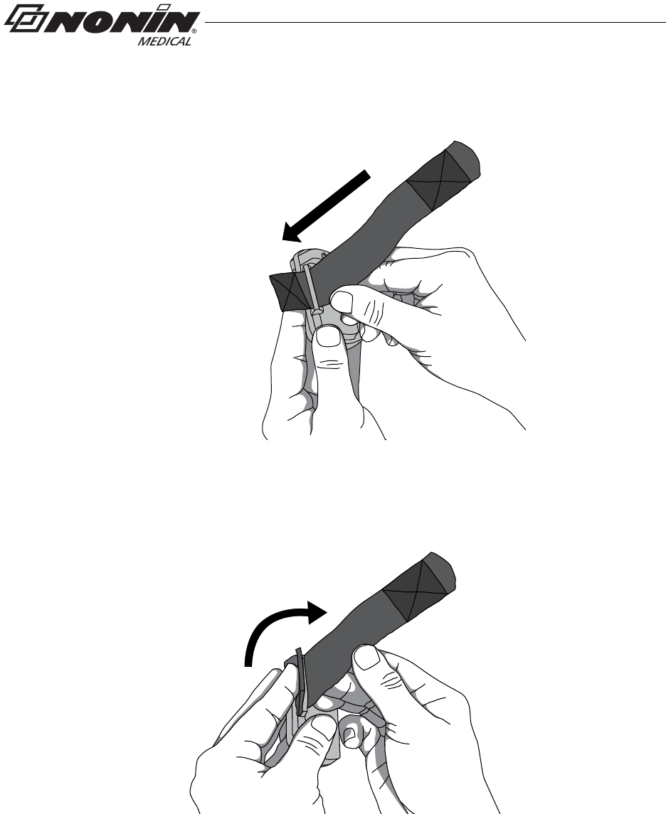
Attach Ring Strap to Device
1. Place device face down.
2. Locate strap bar at top of device (by sensor port).
3. Position ring strap so hook and loop side of strap faces up.
4. Thread square end fastener through the strap bar by the sensor port. Start from
the back of the device and thread it towards the front of the device (figure 6).
.
Strap bar at
top of device
(by sensor port)
Figure 6: Thread Ring Strap
5. Fold strap so fastener adheres to the strap (figure 7).
Figure 7: Attach Ring Strap
6. Continue to “Attach Adjustable Strap to Device.”
15
Using the WristOx2, Model 3150
Adjustable Strap Description
This strap is part of the two-piece wrist band and may also be used to apply the device
using a single strap.
The adjustable strap is available in various lengths (see “Parts and Accessories”). It has
hook and loop fasteners at both ends (figure 8).
The square end attaches to the strap bar at the bottom of the device, by the battery door
(see “Attach Adjustable Strap to Device” section).
Hook and Loop Side
Woven Side
Attach square end
to strap bar by
battery door
Rounded End Fastener
Square End
Fastener
Figure 8: Adjustable Strap
Attach Adjustable Strap to Device
1. Place device face down.
2. Locate strap bar at bottom of device (by battery door).
3. Position adjustable strap so hook and loop side of strap faces up.
16
Using the WristOx2, Model 3150
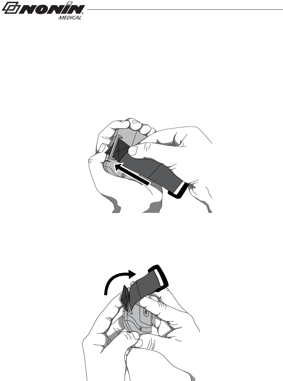
4. Thread square end fastener through the strap bar by the battery door. Start from
the back of the device and thread it towards the front of the device (figure 9).
Strap bar by
battery door
Figure 9: Thread Adjustable Wrist Strap
5. Fold square end of strap so square end fastener adheres to the strap (figure 10).
Figure 10: Attach Adjustable Wrist Strap
17
Using the WristOx2, Model 3150
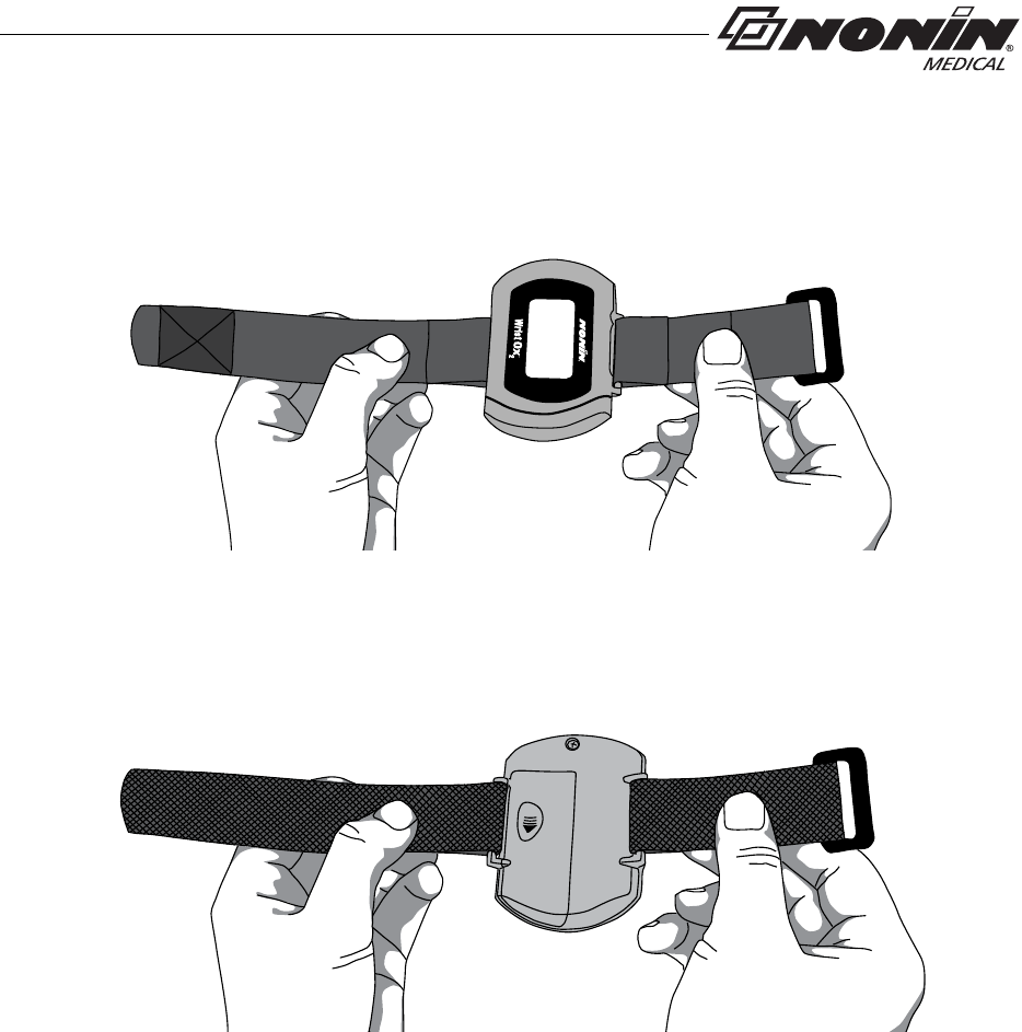
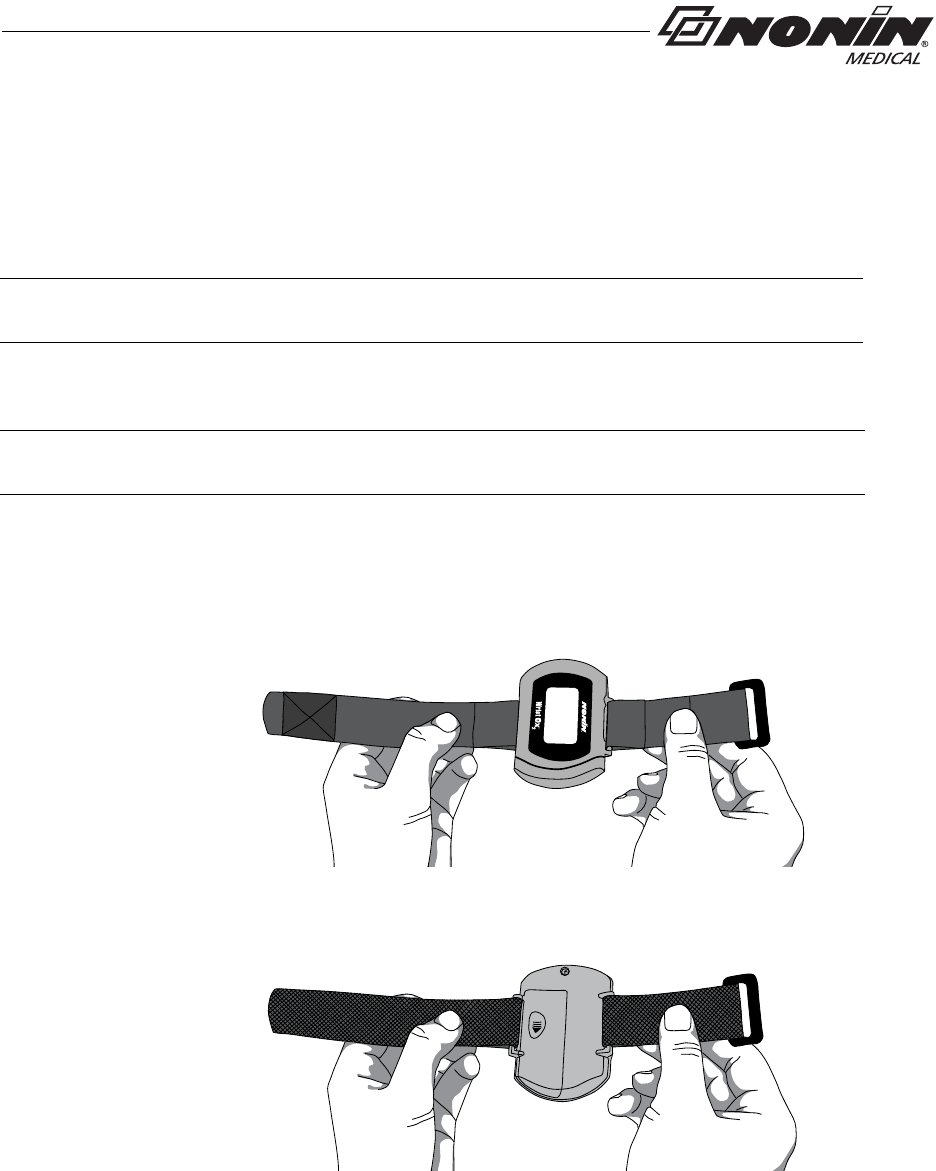
6. Verify straps are attached properly (figure 11). The smooth, woven side of the
strap should contact the patient.
Front View
Back View
Figure 11: Device with Wrist Straps Attached (Front and Back Views)
18
Using the WristOx2, Model 3150
Attaching the Sensor
When applying the device using a single strap, connect the sensor to the device after the
device has been applied to the patient (see “Single Strap Application”).
When using a two-piece wrist band, the sensor can be connected to the device before or
after applying the device to the patient (see “Two-Piece Wrist Band Application”).
The following steps apply to these Nonin sensors:
• 8000SS-WO2, 8000SM-WO2, 8000SL-WO2
• 8000AA-WO2
• 8000J-WO2
If using another Nonin-branded sensor, use sensor adapter cable 3150I (see “Parts and
Accessories”).
!
CAUTION: Only use Nonin-branded sensors with a length of 1 meter or less.
Accuracy may degrade if sensor cable is over 1 meter in length. Using the sensor
cable adapter does not affect accuracy.
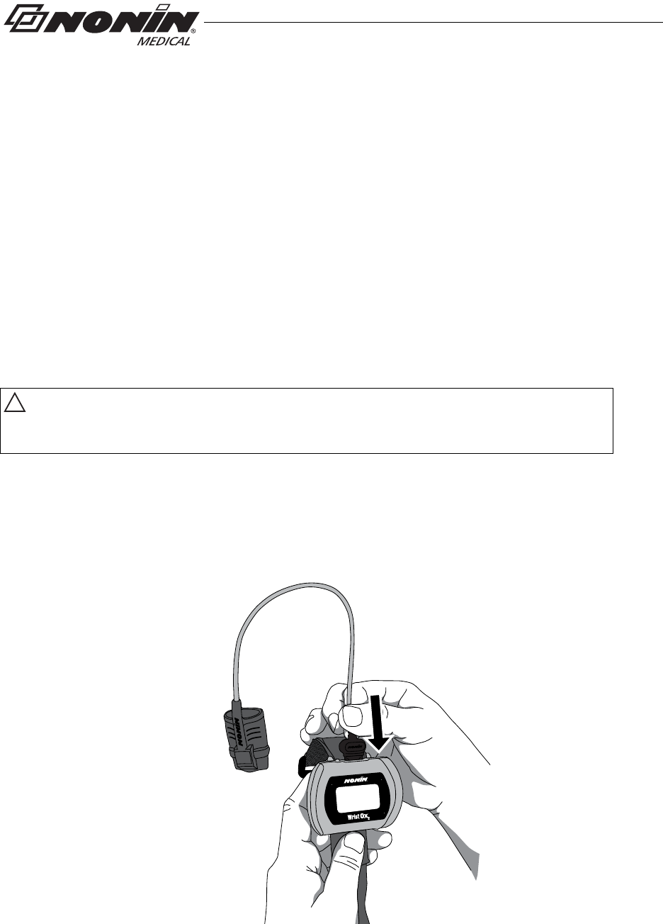
1. Insert the sensor connector into the sensor port at the top of the device (figure 12).
The Nonin logo on the sensor connector should face the front of the device.
2. Push the connector until it clicks into place.
3. The device is ready to use.
Figure 12: Attach Sensor
19
Using the WristOx2, Model 3150
Patient Application
The WristOx2, Model 3150, is usually worn on the back of a patient’s wrist. This section
describes how to secure the device to a wrist using either the two-piece wrist band or a
single strap.
Two-Piece Wrist Band Application
1. Verify the ring strap and the adjustable strap have been attached properly to the
device (figure 13). If straps have not been attached to the device, see “Attach Ring
Strap to Device” and “Attach Adjustable Strap to Device.”
Back View
Front View
Figure 13: Verify Two-Piece Wrist Band Attachment
NOTE: Straps can be used to secure the device to an alternate location (e.g., the upper
arm or a bed rail). See “Part and Accessories” for additional strap lengths.
NOTE: Ensure the wrist band fits comfortably on the patient’s arm. Do not over-tighten
the wrist band.
20
Using the WristOx2, Model 3150
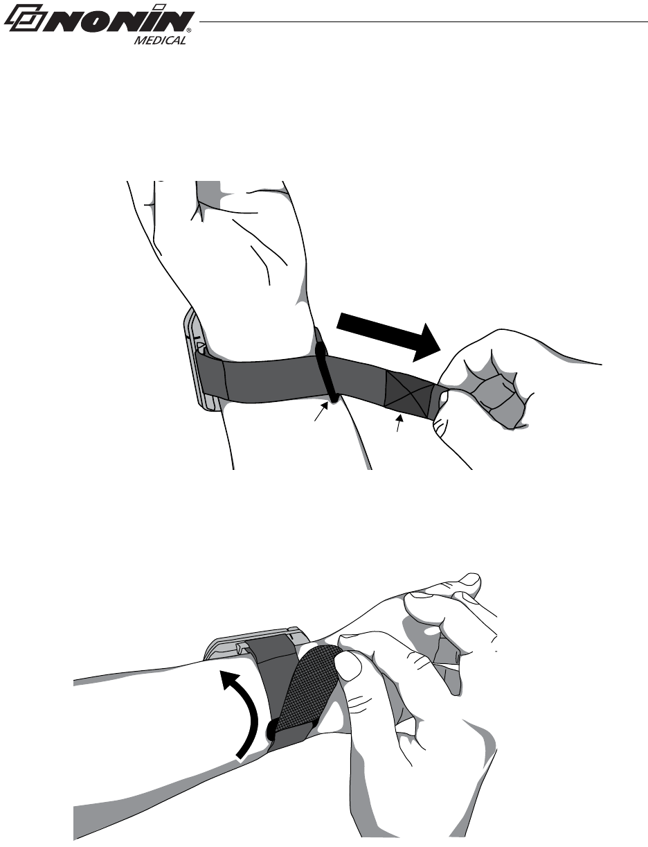
2. Place the device on the back of the patient’s arm.
3. Thread the rounded end of the adjustable strap through the plastic ring on the ring
strap. Pull the adjustable strap through the plastic ring until the device fits comfortably
on the wrist (figure 14).
Fastener
Plastic
Ring
Figure 14: Thread and Tighten Two-Piece Wrist Band
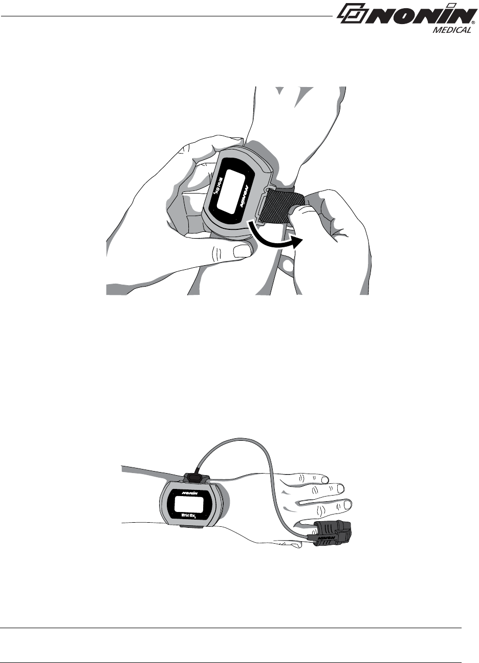
4. Fold the adjustable strap back over the plastic ring and attach the fastener to the
adjustable strap (figure 15).
Figure 15: Fasten Two-Piece Wrist Band
5. Attach the sensor if it is not already connected (see “Attaching the Sensor”).
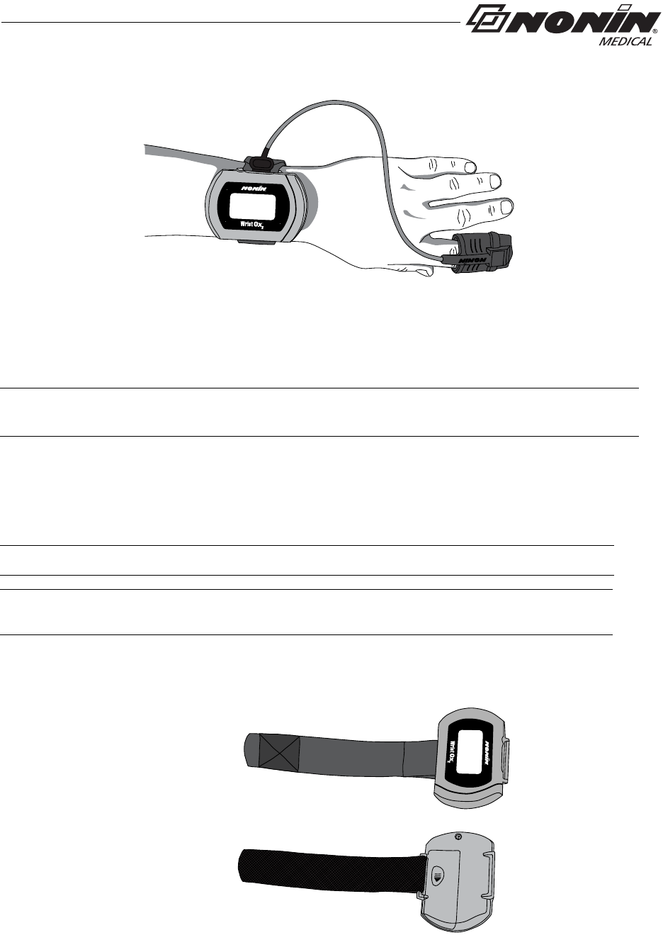
6. Apply the sensor to the patient (figure 16). Refer to the sensor Instructions for Use for
proper sensor application sites and sensor application cautions and warnings.
21
Using the WristOx2, Model 3150
Figure 16: Apply Sensor to Patient
7. When in Spot Check mode, inserting a finger in the sensor automatically turns the
device on. When the finger is removed, the device enters Standby mode in
approximately 10 seconds.
8. If the device does not turn on, verify battery orientation, operation mode, and sensor
connection. Refer to “Troubleshooting” for additional information.
Single Strap Application
1. Verify the adjustable strap has been attached to the device by the battery door
(figure 17). If strap has not been attached, see “Attach Adjustable Strap to Device.”
Front View
Back View
Figure 17: Verify Single Strap Attachment
NOTE: Depending on the sensor and ambient light conditions, it may take up to 3 minutes
for the device to enter Standby mode.
NOTE: Patients using a single strap may need assistance applying the device.
NOTE: Ensure the wrist band fits comfortably on the patient’s arm. Do not over-tighten
the wrist band.
22
Using the WristOx2, Model 3150
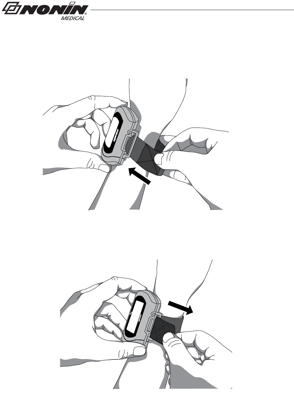
2. Place the device on the back of the patient’s arm and wrap the strap around the
patient’s arm.
3. Thread the rounded end of the strap through the strap bar by the sensor port (figure 18).
Start from the back of the device and pull it towards the front of the device.
Figure 18: Thread Single Strap
4. Pull the strap through the strap bar until the device fits comfortably on the patient’s
wrist (figure 19).
Figure 19: Tighten Single Strap
23
Using the WristOx2, Model 3150
5. Fold the strap over the strap bar so the fastener attaches to the strap (figure 20).
Figure 20: Fasten Single Strap
6. Attach the sensor by inserting the sensor connector into the sensor port at the top of
the device. The Nonin logo on the sensor connector should face the front of the
device. (See “Attaching the Sensor” for more information.)
7. Push the connector until it clicks into place.
8. Apply the sensor to the patient (figure 21). Refer to the sensor Instructions for Use for
proper sensor application sites and sensor application cautions and warnings.
Figure 21: Apply Sensor to Patient
9. When in Spot Check mode, inserting a finger in the sensor automatically turns the
device on. When the finger is removed, the device goes into Standby mode in
approximately 10 seconds.
10. If the device does not turn on, verify battery orientation, operation mode, and sensor
connection. Refer to “Troubleshooting” for additional information.
NOTE: Depending on the sensor and ambient light conditions, it may take up to 3 minutes
for the device to enter Standby mode.
24
Using the WristOx2, Model 3150
Verifying Operation
When the WristOx2, Model 3150, first turns on, it performs a startup sequence and self-
test. It occurs:
• When a sensor is applied to a patient (Spot Check mode).
• When a sensor is attached to the device (Sensor Activation mode).
• At a programmed start time when a sensor is attached to the device (Programmed
mode).
• After the activation switch is pressed while the device is in Standby mode.
• After the device disconnects from nVISION (Bluetooth connection only).
Verify all indicators display during the startup sequence. Indicators appear in the following
order for 1 second each.
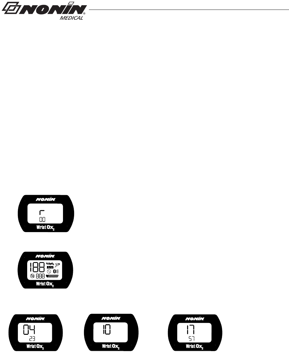
Startup Sequence and Self-Test
If the time is not set, the device displays 01:01:10:00:00.
If any indicator does not display, do not use the device. Contact Nonin Technical Service
for assistance.
1. r and the software revision level:
2. All display icons:
3. Date/time using 24-hour clock format (MM:DD:YY:HH:MM)
(example shows 23 April 2010 at 5:57 p.m.):
Month and Day Year
(MM:DD) (YY) Hour and Minutes
(HH:MM)

25
Using the WristOx2, Model 3150
Activation Switch
The activation switch is located next to the sensor port at the top of the WristOx2, Model
3150. It is primarily used to:
• Activate the Bluetooth radio when the device is either on or in Standby.
• Activate the device when it is in Sensor Activation mode so the user does not need to disconnect
and reconnect the sensor.
It will also activate the device when it is in Spot Check and Programmed modes.
Activate Bluetooth Radio
When the device’s Bluetooth radio is on, a master device can connect to it. If a connection
is not made, the Bluetooth radio shuts down.
Pressing the activation switch turns the Bluetooth radio on for 3 minutes. The device will
remain on until the Bluetooth radio shuts down. For example, if in Sensor Activation mode,
unplugging the sensor will not put the device in Standby.
Activate Device
When in Sensor Activation mode, the device enters Standby mode after 10 minutes without
a signal. Pressing the activation switch allows the user to turn the device on without
disconnecting and reconnecting the sensor.
Error Codes
This device includes error codes that indicate problems with the unit. When an error
occurs, the device displays the letters “Er” and a two-digit code (table 2).
Table 2: Error Codes
Some error codes may be corrected by the user. See “Troubleshooting” for more
information.
Error Code Description
01 Configuration sector error
02 Patient data pointer error
03 Main memory pointer error (Device memory is intact; however, the most
recent session may be missing from the device.)
04 Data format 13 stored packet pointer error
05 Main data format 13 pointer error (Device memory is intact; however, the
most recent stored measurement may be missing from the device.)

26
Troubleshooting
Troubleshooting
Problem Possible Cause Possible Solution
Device will not
activate. Batteries inserted wrong. Check batteries.
Batteries are depleted. Replace batteries.
Sensor is disconnected. Reconnect sensor.
Device is in Sensor Activation
mode and has timed out. Press the activation switch.
Disconnect and then reconnect the
sensor.
Device is in Programmed mode. Use nVISION software to select Spot
Check or Sensor Activation mode.
%SpO2 and pulse rate
do not display. Device set in Partial Display
mode. Use nVISION software to select Full
Display mode. Reconnect sensor.
Poor pulse signal
indicator displays. Excessive patient motion. Reduce patient motion.
Poor pulse signal
indicator displays
and
pulse strength
indicator shows two
bars or less.
Inadequate pulse signal. Reposition or replace sensor, or place
sensor on a different finger.
Remove and reconnect sensor.
Hands are cold. Warm sensor application site.
No pulse display on
pulse strength bar
graph indicator.
Sensor applied incorrectly. Refer to sensor Instructions for Use
for proper sensor application.
Device needs repair. Contact Nonin Technical Service.
Possible interference from blood
flow restrictors (arterial catheters,
blood pressure cuffs, infusion
lines, etc.).
Reduce or eliminate restriction.
Reduced circulation due to excess
pressure from sensor. Check sensor alignment, reposition
sensor, verify correct sensor size.
Excessive ambient light. Shield sensor from light source.
Check sensor alignment.

27
Troubleshooting
If these solutions do not correct the problem, please contact Nonin Technical Service at
(800) 356-8874 (USA and Canada) or + 1 (763) 553-9968.
No pulse display on
pulse strength
indicator (continued).
Sensor applied to polished or
artificial nail. Remove fingernail polish or an
artificial nail.
Sensor Light-Emitting Diode
(LED) is not lit. Contact Nonin Technical Service.
Er 01 displays on
LCD. Device configuration memory
failure. Device reverts to default settings
(Spot-Check mode, 4-second sample
rate). Use nVISION software to
change settings. If error code
continues, contact Nonin Technical
Service.
Er 02 or 04 displays
on LCD. Device memory failure. Contact Nonin Technical Service.
Er 03 or 05
displays on LCD. Device failure. Device memory
intact, but device may have lost
most recent session or stored
data.
If error code continues, contact Nonin
Technical Service.
Dashes continually
display on LCD. Sensor malfunction. Replace sensor with a Nonin-branded
sensor.
Device does not
record in
Programmed mode.
Data collection start and stop
times are set incorrectly. Use nVISION software to program
correct start and stop times.
Clock settings are lost after
replacing batteries. Use nVISION software to reset clock.
Devices will not pair. Device is out of range. Verify device is in range while being
paired (approximately 100 meters
[328 feet] spherical radius).
Bluetooth radio has timed out. Press activation switch to turn on
Bluetooth radio.
Problem Possible Cause Possible Solution

28
Care and Maintenance
Care and Maintenance
The device requires no calibration or maintenance other than battery replacement.
Cleaning the Device
Wipe the device with a soft cloth dampened with a 10% bleach solution. Do not use
undiluted bleach or any cleaning solution other than those recommended here, as
permanent damage could result. Dry with a soft cloth, or allow to air dry.
Clean once per week or more frequently if handled by multiple users.
!
CAUTION: Do not place the WristOx2, Model 3150, in liquid or clean it with agents
containing ammonium chloride or isopropyl alcohol.
Cleaning the Sensor
Refer to the sensor Instructions for Use for cleaning information.
Cleaning the Wrist Band
The wrist band is designed for single-patient use and may be used up to 10 times.
If it needs to be cleaned, hand wash with a mild detergent (see note) in cool water (30 °C/
86 °F). Allow to air dry.
Do not machine wash or dry. The wrist band will shrink if placed in a dryer.
CAUTION: Use a detergent that is safe for skin and washable surfaces. Most detergents
can be high sudsing, so use sparingly. Wipe with a damp, detergent free cloth to remove
residue.
Storing
Store the device within the stated environmental specifications. See “Specifications” for
additional information.
Remove the batteries and disconnect the sensor if it is to be stored for more than 1 month.
NOTE: Mild detergents, such as hand and dish washing liquid detergents, dissolve dirt
and grease. To clean washable surfaces, use in a solution of warm water.

29
Memory and Data
Memory and Data
The WristOx2, Model 3150 measures, collects, and stores up to 1,080 hours
of SpO2 and pulse rate data with a 4-second data collection rate. Data collected at a
1 or 2-second rate reduces memory capacity to 270 or 540 hours, respectively.
When the memory is full, the device overwrites the oldest existing data with the new data.
Each time the device is turned on, data are automatically stored in memory. Data collection
of less than 1 minute is not retained in memory.
Each time the device turns on, the current oximeter time and date (if the clock is set
properly) are stored in memory to allow quick differentiation of recording sessions. Patient
SpO2 and pulse rate are stored every 4 seconds (default), or every 1 or 2 seconds if
programmed using nVISION software. The oxygen saturation values are stored in
1% increments in the range of 0 to 100%.
This device contains non-volatile memory. Removing or replacing batteries does not affect
the data stored in memory. Stored data remains in memory until overwritten by newer data
or cleared from memory with nVISION software.
NOTE: Downloading data in memory does not clear memory. To clear memory, see
“nVISION Settings.”

30
nVISION Software
nVISION Software
Nonin’s nVISION software (version 6.3 or greater) works with Microsoft Windows® 2000/
XP/Vista/7 operating systems. It allows users to transfer recorded patient data from the
device to a PC and then analyze, report, and archive the data. The software is required to
access the device’s additional modes of operation and advanced features.
nVISION Settings
The following WristOx2, Model 3150, settings are programmed using nVISION:
• Date and time – 24-hour clock format
• Display options – allows clinicians to choose the best display option for each patient:
• Full display shows %SpO2 and pulse rate data
• Partial display shows pulse strength indicator, but not %SpO2 and pulse rate data
• Patient data storage (sample) rate – 1, 2, or 4 seconds
• Operation Modes – Sensor Activation, Spot Checking, and Programmed (see
“Activation Options”)
• Patient ID – up to 50 alphanumeric characters
• Bluetooth Radio – disable at startup
• Synchronize device time/date to the PC time/date
• Download and save patient data to a PC
• Clear device memory
To access nVISION settings, connect the device to a PC using either the PC USB interface
cable or a Bluetooth connection.
Accessing nVISION Settings
1. Connect the device to a PC using the USB interface cable (see “Cable Connection”)
or Bluetooth (see “Bluetooth Connection”).
2. Open nVISION.
3. Click the Data Capture icon, or select New Data Capture from the File drop down
menu.
4. Select 3150 from the list of oximeters.
5. Click Settings.
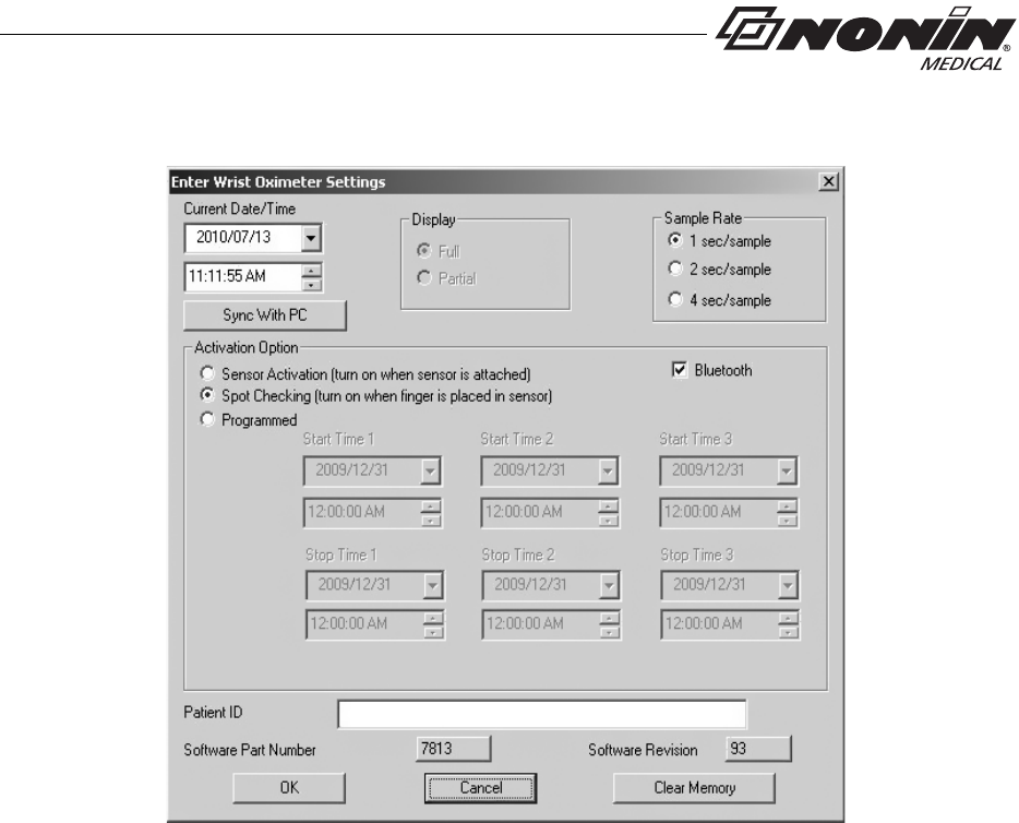
6. “Enter Wrist Oximeter Settings” window opens (figure 22). Update or change settings
as needed.
7. Click OK.
8. For more information, see nViSION Help.
31
nVISION Software
.
Figure 22: nVISION Settings Window
Cable Connection
To connect the device to a PC, use the PC USB interface cable found in the starter kit.
Once connected to a PC, the device settings may be accessed and data can be
downloaded using nVISION software.
The USB driver software for the cable needs to be installed before the device can connect
to the PC. The software is located in the USB Driver folder on the Operator’s Manual CD.
1. Install USB driver if needed. See appropriate “USB Driver Installation” section for
more information.
2. Connect the cable to the USB port on the PC.
3. Connect the cable to the device’s sensor port.

32
nVISION Software
4. When the device is ready to use with nVISION, these indicators display on the LCD:
•CP
• Battery indicator
5. For more information about nVISION, refer to nVISION Help.
USB Driver Installation (XP)
1. The USB driver software is on the Operator’s Manual CD. Insert the CD into the PC’s
CD-DVD drive.
2. Connect the USB cable to the sensor port on the device and a USB port on the PC.
3. The Found New Hardware wizard opens and asks if Windows should connect to
Windows Update to search for software. Select No, not this time and click Next.
4. Select Install from a list or specific location (Advanced) and click Next.
5. When asked to choose search and installation options:
a. Select Search for the best driver in these locations.
b. Unselect Search removable media
c. Select Include this location in the search:
d. Browse to the USB Driver folder on the Operator’s Manual CD and click OK.
e. Click Next.
6. If the Hardware Installation/Windows logo testing window appears, click Continue
Anyway to continue the installation.
7. When the wizard is done with the software installation, click Finish.
8. Look up the communications (comm or COM) port for the device:
a. Click Start / Settings / Control Panel.
b. Select System. System Properties window opens.
c. On the Hardware tab, select Device Manager.
d. Expand Ports (COM & LPT). One port should say “Nonin Model 3150 (COM#).”
Make a note of the COM#. It is needed to set up the device with nVISION.
NOTE: Disconnect the USB interface cable from the device when the data transfer or
device configuration is complete. Leaving the cable connected will reduce battery life.

33
nVISION Software
USB Driver Installation (Vista)
1. Connect the USB cable to the sensor port on the device and a USB port on the PC.
2. In the Found New Hardware window, select Locate and install driver software
(recommended).
3. Windows needs your permission to continue pop up appears. Continue with
installation.
4. The USB driver software is on the Operator’s Manual CD. Insert the CD into the PC’s
CD-DVD drive and click Next.
5. Update Driver Software - Model 3150 window opens. Choose Browse my computer
for driver software.
6. Browse to the USB Driver folder on the Operator’s Manual CD and click OK.
7. Click Next.
8. In the Windows Security pop-up window, select Install this driver software anyway.
9. Driver software installs. When Windows has successfully updated the driver software,
click Close.
10. Open the Device Manager by clicking Start / Control Panel / Device Manager.
11. In the Device Manager window, look up the communications (comm or COM) port for the
device. Expand Ports (COM & LPT). One port should say “Nonin Model 3150 (COM#).”
Make a note of the COM#. It is needed to set up the device with nVISION.
USB Driver Installation (Windows 7)
1. The USB driver software is on the Operator’s Manual CD. Insert the CD into the PC’s
CD-DVD drive.
2. Connect the USB cable to the sensor port on the device and a USB port on the PC.
3. Open the Device Manager by clicking Start / Control Panel / System and then
selecting Device Manager.
4. Expand Other devices.
5. Right click Model 3150 and select Update Driver Software...
6. Update Driver Software - Model 3150 window opens. Choose Browse my computer
for driver software.
7. Browse to the USB Driver folder on the Operator’s Manual CD and click OK.
8. Click Next.
9. In the Windows Security pop-up window, select Install this driver software anyway.
10. Driver software installs. When Windows has successfully updated the driver software,
click Close.
11. In the Device Manager window, look up the communications (comm or COM) port for the
device. Expand Ports (COM & LPT). One port should say “Nonin Model 3150 (COM#).”
Make a note of the COM#. It is needed to set up the device with nVISION.
34
nVISION Software
Bluetooth Connection
Before a Bluetooth master device can connect with the WristOx2, Model 3150 (slave
device), the devices must be paired. Once paired, the WristOx2, Model 3150, will
automatically connect with the last paired master device when turned on or activated.
1. To connect the WristOx2, Model 3150, to a PC or another device using Bluetooth, see
Nonin’s online Bluetooth Connection Tutorial:
http://www.nonin.com/training/products/3150/bluetooth_connection_tutorial/
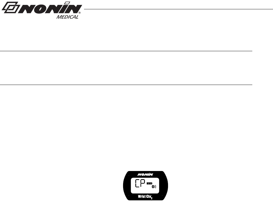
2. When nVISION connects to the WristOx2, Model 3150, the device stops recording
patient data and the following indicators display on the LCD:
•CP
• Battery indicator
• Bluetooth icon with animated bars
3. For more information about nVISION, refer to nVISION Help.
NOTE: Etched onto the device is the word “pin” followed by a 6-digit number. This is the
device’s unique identification number, also known as the Bluetooth Passkey or PIN
Code. This number is used when pairing the device to the host system. Refer to the host
system’s operator’s manual for additional information.

35
Parts and Accessories
Parts and Accessories
For more information about Nonin parts, accessories and sensors, contact your distributor,
or contact Nonin at (800) 356-8874 (USA and Canada) or +1 (763) 553-9968. This
information is also available on Nonin’s website: www.nonin.com.
Model Number Description
Reusable Pulse Oximeter Sensors
3100CC Carrying Case
3150 Manual CD with Operator’s Manual and USB Driver Software
3150SC PC USB Interface Cable
nVISION nVISION Software (version 6.3 or greater). Used with Microsoft
Windows 2000/XP/Vista/7 operating systems.
3150I Sensor Adapter Cable. Used to connect 1-meter, 9-pin connector
sensors to the WristOx2, Model 3150. For compatible 1-meter
sensors, contact Nonin, your distributor, or visit www.nonin.com.
3150WB Two-piece Wrist Band. Available lengths:
6 in. (15 cm)
8 in. (20 cm)
10 in. (25 cm)
13 in. (33 cm)
3150WBE Wrist Band Extender, 5 in. (13 cm)
8000AA-WO2 Adult Articulated Finger Clip Sensor
8000J-WO2 Adult Flex Sensor
8000SS-WO2 Soft Sensor Small
8000SM-WO2 Soft Sensor Medium
8000SL-WO2 Soft Sensor Large

36
Service, Support, and Warranty
Service, Support, and Warranty
Service and Support
For information about the device and accessories, contact your local sales representative
or distributor. For the sales representative or distributor in your area, contact Nonin.
A return authorization number is required before returning any product to Nonin. To obtain
this return authorization number, contact Nonin’s Technical Service Department at:
Nonin Medical, Inc.
13700 1st Avenue North
Plymouth, Minnesota 55441-5443 USA
(800) 356-8874 (USA and Canada)
+ 1 (763) 553-9968
Fax: + 1 (763) 553-7807
E-mail: info@nonin.com
www.nonin.com
Warranty
NONIN MEDICAL, INCORPORATED, (NONIN) warrants to the purchaser the Model 3150,
WristOx2 Pulse Oximeter for 3 years from the date of purchase. NONIN shall repair or replace any
WristOx2, Model 3150, found to be defective in accordance with this warranty, free of charge, for
which NONIN has been notified by the purchaser by serial number that there is a defect, provided
said notification occurs within the applicable warranty period. This warranty shall be the sole and
exclusive remedy by the purchaser hereunder for any WristOx2, Model 3150, delivered to the
purchaser that is found to be defective in any manner, whether such remedies be in contract, tort,
or by law.
This warranty excludes cost of delivery to and from NONIN. All repaired units shall be received by
the purchaser at NONIN’s place of business. NONIN reserves the right to charge a fee for a
warranty repair request on any unit found to be within specifications.
The WristOx2, Model 3150, is a precision electronic instrument and must be repaired by
knowledgeable and specially trained NONIN personnel only. Accordingly, any sign or evidence of
opening the WristOx2, Model 3150, field service by non-NONIN personnel, tampering, or any kind
of misuse of the WristOx2, Model 3150, shall void the warranty.
All non-warranty work shall be performed according to NONIN standard rates and charges in
effect at the time of delivery to NONIN.
DISCLAIMER/EXCLUSIVITY OF WARRANTY:
THE WARRANTIES IN THIS MANUAL ARE EXCLUSIVE, AND NO OTHER WARRANTIES OF
ANY KIND, WHETHER STATUTORY, WRITTEN, ORAL, OR IMPLIED, SHALL APPLY.

37
Technical Information
Technical Information
Manufacturer’s Declaration
Refer to the following table for specific information regarding this device’s compliance to
IEC 60601-1-2.
Emissions Test Compliance Electromagnetic Environment—Guidance
This device is intended for use in the electromagnetic environment specified below.
The customer and/or user of this device should ensure that it is used in such an environment.
RF Emissions
CISPR 11 Group 2 This device must emit electromagnetic energy in order
to perform its intended function. Nearby electronic
equipment may be affected.
RF Emissions
CISPR 11 Class B This device is suitable for use in all establishments,
including domestic and those directly connected to the
public low-voltage power supply network that supplies
buildings used for domestic purposes.
Harmonic
Emissions
IEC 61000-3-2
N/A
Voltage
Fluctuations/
Flicker Emissions
IEC 61000-3-3
N/A
Table 3: Electromagnetic Emissions

38
Technical Information
Immunity
Test IEC 60601
Test Level Compliance
Level Electromagnetic
Environment—Guidance
This device is intended for use in the electromagnetic environment specified below.
The customer and/or user of this device should ensure that it is used in such an environment.
Electrostatic
Discharge (ESD)
IEC 61000-4-2
±6 kV contact
±8 kV air ±6 kV contact
±8 kV air Floors should be wood, concrete,
or ceramic tile. If floors are
covered with synthetic material,
relative humidity should be at
least 30%.
Electrical Fast
Transient/Burst
IEC 61000-4-4
±2 kV for power supply
lines
±1 kV for input/output lines
N/A Mains power quality should be
that of a typical commercial or
hospital environment.
Surge
IEC 61000-4-5 ±1 kV differential mode
±2 kV common mode N/A Mains power quality should be
that of a typical commercial or
hospital environment.
Voltage dips, short
interruptions, and
voltage variations on
power supply input
lines
IEC 61000-4-11
±5% UT (>95% dip in UT)
for 0.5 cycle
±40% UT (60% dip in UT)
for 5 cycles
±70% UT (30% dip in UT)
for 25 cycles
<5% UT (>95% dip in UT)
for 5 sec.
N/A Mains power quality should be
that of a typical commercial or
hospital environment.
Power Frequency
(50/60 Hz) Magnetic
Field
IEC 61000-4-8
3 A/m 3 A/m Power frequency magnetic fields
should be at levels characteristic
of a typical location in a typical
commercial or hospital
environment.
NOTE: UT is the AC mains voltage before application of the test level.
Table 4: Electromagnetic Immunity
Immunity Test IEC 60601 Test
Level Compliance
Level Electromagnetic Environment—
Guidance
This device is intended for use in the electromagnetic environment specified below.
The customer and/or user of this device should ensure that it is used in such an environment.
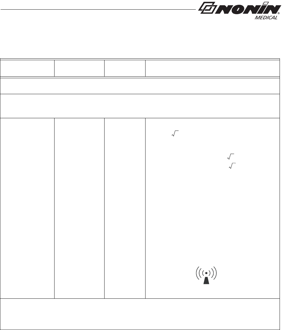
Portable and mobile RF communications equipment should be used no closer to any part of the device,
including cables, than the recommended separation distance calculated from the equation applicable to
the frequency of the transmitter.
Recommended Separation Distance
Conducted RF
IEC 61000-4-6 3 Vrms
150 kHz to 80
MHz
3 Vrms
d1.17 P=
Radiated RF
IEC 61000-4-3 3 V/m
80 MHz to 2.5
GHz
3 V/m
3 V/m
80 kHz to 800 MHz
d1.17 P=
800 MHz to 2.5 GHz
d2.33 P=
where P is the maximum output power rating of
the transmitter in watts (W) according to the
transmitter manufacturer and d is the
recommended separation distance in meters (m).
Field strengths from fixed RF transmitters, as
determined by an electromagnetic site surveya,
should be less than the compliance level in each
frequency range.b
Interference may occur in the vicinity of
equipment marked with the symbol:
NOTES:
1. At 80 MHz and 800 MHz, the higher frequency range applies.
2. These guidelines may not apply in all situations. Electromagnetic propagation is affected by
absorption and reflection from structures, objects, and people.
a. Field strengths from fixed transmitters, such as base stations for radio (cellular/cordless) telephones and land mobile radios, amateur radio, AM
and FM radio broadcast, and TV broadcast cannot be predicted theoretically with accuracy. To assess the electromagnetic environment due to
fixed RF transmitters, an electromagnetic site survey should be considered. If the measured field strength in the location in which the device is
used exceeds the applicable RF compliance level above, the device should be observed to verify normal operation. If abnormal performance is
observed,
additional measures may be necessary, such as reorienting or relocating the device.
b. Over the frequency range 150 kHz to 80 MHz, field strengths should be less than 3 V/m.
39
Technical Information
Table 5: Guidance and Manufacturer’s Declaration—
Electromagnetic Immunity

40
Technical Information
This table details the recommended separation distances between portable and mobile RF
communications equipment and this device
This device is intended for use in an electromagnetic environment in which radiated RF disturbances are controlled. Users
of this device can help prevent electromagnetic interference by maintaining a minimum distance between portable and
mobile RF communication equipment (transmitters) and the device as recommended below, according to maximum output
power of the communications equipment.
Separation Distance According to Frequency of Transmitter
Rated Maximum
Output Power of
Transmitter W
d1.17 P=
150 kHz to 80 MHz
d1.17 P=
80 MHz to 800 MHz
d2.33 P=
800 MHz to 2.5 GHz
0.01 0.12 0.12 0.23
0.1 0.37 0.37 0.73
11.2 1.2 2.3
10 3.7 3.7 7.3
100 12 12 23
For transmitters rated at a maximum output power not listed above, the recommended separation
distance d in meters (m) can be estimated using the equation applicable to the frequency of the
transmitter, where P is the maximum output power rating of the transmitter in watts (W) according to
the transmitter manufacturer.
NOTES:
1. At 80 MHz and 800 MHz, the higher frequency range applies.
2. These guidelines may not apply in all situations. Electromagnetic propagation is affected by
absorption and reflection from structures, objects, and people.
SpO2 Values Average Latency
Pulse Rate Values Response Latency
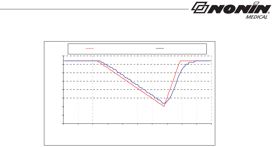
Equipment Response Time
Example - SpO2 Exponential Averaging
SpO2 decreases 0.75% per second (7.5% over 10 seconds)
Pulse Rate = 75 BPM
Table 6: Recommended Separation Distances
Standard/Fast Averaged SpO24 beat exponential 2 beats
Standard/Fast Averaged Pulse Rate 4 beat exponential 2 beats
60
65
70
75
80
85
90
95
100
0.0
8.0
16.0
24.0
32.0
40.0
48.0
56.0
64.0
72.0
80.0
Time in seconds
SpO2
SaO2 Reference 4 Beat Average
41
Technical Information
Specific to this example:
• The response of the 4-beat average is 1.5 seconds.
Testing Summary
SpO2 accuracy and low perfusion testing was conducted by Nonin Medical, Inc., as
described below.
SpO2 Accuracy Testing
SpO2 accuracy testing is conducted during induced hypoxia studies on healthy, non-
smoking, light- to dark-skinned subjects during motion and no-motion conditions in an
independent research laboratory. The measured arterial hemoglobin saturation value
(SpO2) of the sensors is compared to arterial hemoglobin oxygen (SaO2) value,
determined from blood samples with a laboratory co-oximeter. The accuracy of the sensors
in comparison to the co-oximeter samples measured over the SpO2 range of
70 - 100%. Accuracy data is calculated using the root-mean-squared (Arms value) for all
subjects, per ISO 9919:2005, Medical Electrical Equipment—Particular requirements for
the basic safety and essential performance of pulse oximeter equipment for medical use.
Pulse Rate Motion Testing
This test measures pulse rate oximeter accuracy with motion artifact simulation introduced
by a pulse oximeter tester. This test determines whether the oximeter meets the criteria of
ISO 9919:2005 for pulse rate during simulated movement, tremor, and spike motions.
Low Perfusion Testing
This test uses an SpO2 Simulator to provide a simulated pulse rate, with adjustable
amplitude settings at various SpO2 levels for the oximeter to read. The oximeter must
maintain accuracy in accordance with ISO 9919:2005 for heart rate and SpO2 at the lowest
obtainable pulse amplitude (0.3% modulation).

42
Technical Information
Specifications
Oximeter Specifications
Oxygen Saturation Display Range: 0 to 100 % SpO2
Pulse Rate Display Range: 18 to 321 beats per minute (BPM)
Displays:
Numeric: 3-digit LCD
Pulse Strength: Pulse Strength Bar Graph
Saturation Accuracy Armsa:
a. ±1 Arms represents approximately 68% of measurements.
70 % to 100 %
%SpO2: No Motion Motionb
b. SpO2 accuracy in motion specified for 8000AA-W sensor.
Low Perfusion
8000AA-WO2: ±2 units ±2 units ±2 units
8000J-WO2: ±3 units NA ±2 units
8000SM-WO2: ±2 units NA ±2 units
Pulse Rate Accuracy: ±3 units ±3 units ±3 units
Measurement Wavelengths and Output Powerc:
c. This information is especially useful for clinicians performing photodynamic therapy.
Red: 660 nanometers @ 0.8 mW max. avg.
Infrared: 910 nanometers @ 1.2 mW max. avg.

43
Technical Information
System Specifications
Temperature:
Operating: -5 °C to 40 °C (23 °F to 104 °F)
Storage/Transportation: -40 °C to 70 °C (-40 °F to 158 °F)
Humidity:
Operating: 10 % to 95 % noncondensing
Storage/Transportation: 10 % to 95 % noncondensing
Operating Altitude: Up to 12,192 meters (40,000 feet)
Operating Hyperbaric Pressure: Up to 4 atmospheres
Power Requirements: Two AAA (1.5V) alkaline batteries
Battery Life:
Storage: Approx. 9 months
Operating without Bluetooth: Approx. 48 hours (minimum) of continuous
operation
Operating with Bluetooth radio – Class 1a:
a. When operating with Bluetooth, typical battery life may vary depending on proximity to host connection
and configuration of host-to-device communications. Times provided are minimum times for common
configurations.
Approx. 8 hours minimum
Operating with Bluetooth radio – Class 2: Approx. 24 hours minimum
Dimensions (without sensor or strap): 51 mm x 73 mm x 19 mm (H x W x D)
(2.0 in. x 2.9 in. x 0.75 in.)
Weight (with batteries and wrist strap): 64.0 g (2.3 oz)
Memory:
Type: Non-volatile
Capacity: up to 1,080 hours (4 sec. data storage rate)
up to 540 hours (2 sec. data storage rate)
up to 270 hours (1 sec. data storage rate)
Classification per IEC 60601-1 / CAN/CSA-C22.2 No. 601.1 / UL60601-1:
Type of Protection: Internally powered (battery power)
Degree of Protection: Type BF-Applied Part
Mode of Operation: Continuous
Enclosure Degree of Ingress Protection: IP33

44
Technical Information
Transmitter
Bluetooth Compliance: Version 2.0
Operating Frequency: 2.4 to 2.4835 GHz
Output Power: < 20 dBm
Operating Range: 100-meter (328-foot) radius indoors
Network Topology: Point-to-Point
Operation: Slave
Antenna Type: Internal
Modulation Type: Frequency Shift Keying
Frequency Hopping Spread Spectrum
Band Width: 1 MHz