Nordic ID NUR0W1 Nordic ID UHF RFID Radio module NUR-0W1 User Manual Hardware implementation guide
Nordic ID Oy Nordic ID UHF RFID Radio module NUR-0W1 Hardware implementation guide
Contents
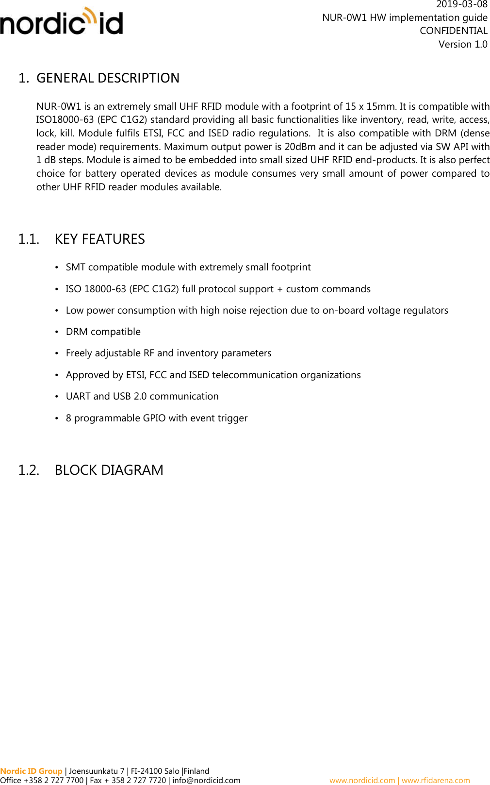
- 1. Hardware implementation guide
- 2. RF Safety Training Leaflet
- 3. Data Sheet
- 4. Quick Guide
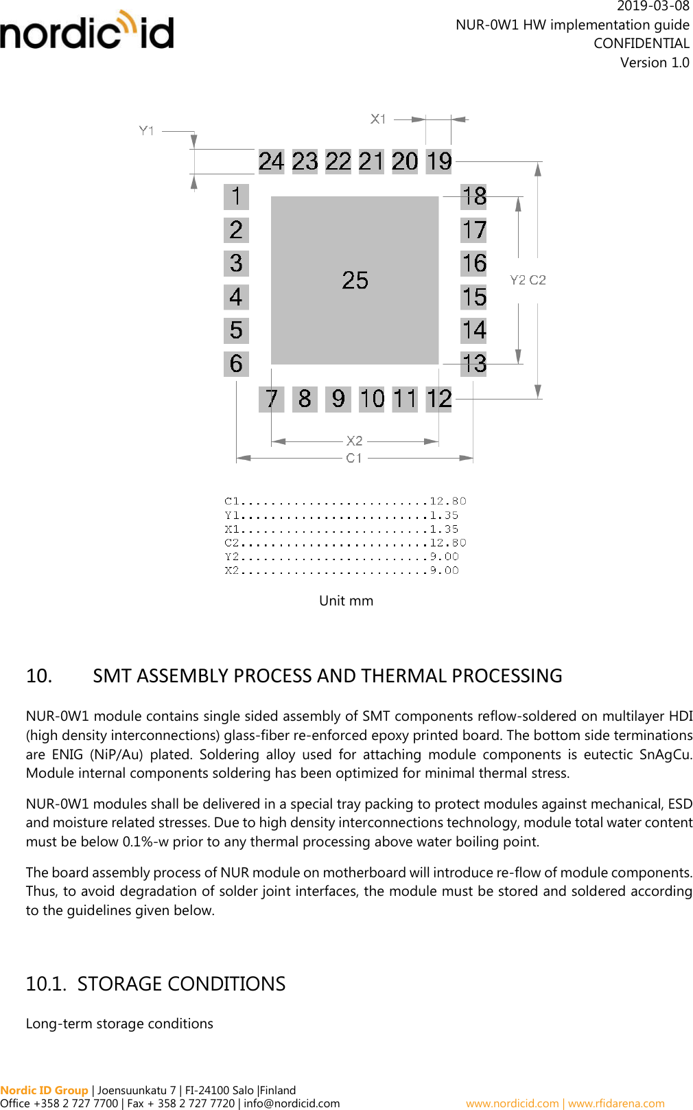
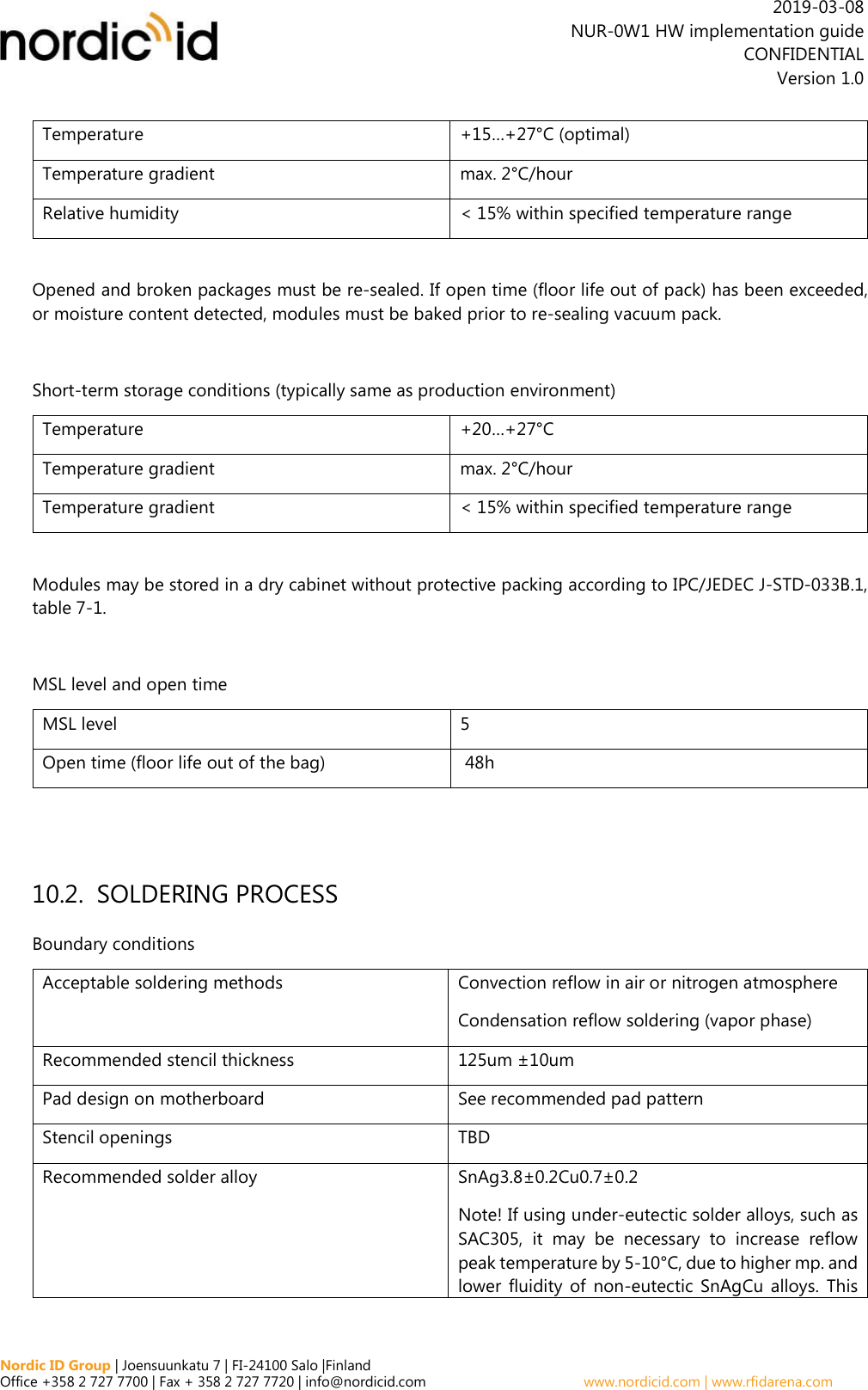
Hardware implementation guide
![Nordic ID Group | Joensuunkatu 7 | FI-24100 Salo |Finland Office +358 2 727 7700 | Fax + 358 2 727 7720 | info@nordicid.com www.nordicid.com | www.rfidarena.com 2019-03-08 NUR-0W1 HW implementation guide CONFIDENTIAL Version 1.0 When leveraging Nordic ID’s grants and certifications, antenna shall be considered in view of the fact that the NUR-0W1 module has met the essential regulatory requirements with the antennas listed in the context of particular regulatory compliance information (Approved Antennas). Using the antenna that is an approved one, OEM integrator may demonstrate with less effort that the device with the integrated NUR-0W1 module complies with the requirements. 11.1. EUROPEAN UNION AND EFTA COUNTRIES USER GUIDE REQUIREMENTS This apparatus complies the essential requirements of the Radio Equipment Directive (RED) 2014/53/EU. In order to prove presumption of conformity with the essential requirements of the Radio Equipment Directive (RED) 2014/53/EU, following requirements and test methods have been applied to the apparatus: article 3.2: ETSI EN 302 208 v3.1.1 - Radio spectrum matters for Radio Frequency Identification (RFID) equipment operating in the band 865 MHz to 868 MHz with power levels up to 2W article 3.1b: ETSI EN 301 489-1 v2.2.0 - Common ElectroMagnetic Compatibility (EMC) requirements article 3.1b: ETSI EN 301 489-3 v2.1.1 - Specific ElectroMagnetic Compatibility (EMC) conditions for Short-Range Devices (SRD) operating on frequencies between 9 kHz and 246 GHz article 3.1a: EN 60950-1:2006 + A1:2010 + A11:2009+A12:2011+ A2:2013 - General requirements for Safety of Information Technology Equipment EN 62479: 2010 - Human exposure EN 62311: 2008 - Human exposure limits This apparatus complies EU Directive 2011/65/EU, Reduction of Hazardous Substances (RoHS). Česky [Czech] [Nordic ID] tímto prohlašuje, že tento [RFID Radio module NUR-0W1] je ve shodě sezákladními požadavky a dalšími příslušnými ustanoveními směrnice 2014/53/ES.](https://usermanual.wiki/Nordic-ID/NUR0W1.Hardware-implementation-guide/User-Guide-4195545-Page-22.png)
![Nordic ID Group | Joensuunkatu 7 | FI-24100 Salo |Finland Office +358 2 727 7700 | Fax + 358 2 727 7720 | info@nordicid.com www.nordicid.com | www.rfidarena.com 2019-03-08 NUR-0W1 HW implementation guide CONFIDENTIAL Version 1.0 Dansk [Danish] Undertegnede [Nordic ID] erklærer herved, at følgende udstyr [RFID Radio module NUR-0W1] overholder de væsentlige krav og øvrige relevante krav i direktiv 2014/53/EF. Deutsch [German] Hiermit erklärt [Nordic ID], dass sich das Gerät [RFID Radio module NUR-0W1] in Übereinstimmung mit den grundlegenden Anforderungen und den übrigen einschlägigen Bestimmungen der Richtlinie 2014/53/EG befindet. Eesti [Estonian] Käesolevaga kinnitab [Nordic ID] seadme [RFID Radio module NUR-0W1] vastavust direktiivi 2014/53/EÜ põhinõuetele ja nimetatud direktiivist tulenevatele teistele asjakohastele sätetele. English Hereby, [Nordic ID], declares that this [RFID Radio module NUR-0W1] complies with the essential requirements and other relevant provisions of Directive 2014/53/EU. Español [Spanish] Por medio de la presente [Nordic ID] declara que el [RFID Radio module NUR-0W1] cumple con los requisitos esenciales y cualesquiera otras disposiciones aplicables o exigibles de la Directiva 2014/53/EU. Ελληνική [Greek] ΜΕ ΤΗΝ ΠΑΡΟΥΣΑ [Nordic ID] ΔΗΛΩΝΕΙ ΟΤΙ [RFID Radio module NUR-0W1] ΣΥΜΜΟΡΦΩΝΕΤΑΙ ΠΡΟΣ ΤΙΣ ΟΥΣΙΩΔΕΙΣ ΑΠΑΙΤΗΣΕΙΣ ΚΑΙ ΤΙΣ ΛΟΙΠΕΣ ΣΧΕΤΙΚΕΣ ΔΙΑΤΑΞΕΙΣ ΤΗΣ ΟΔΗΓΙΑΣ 2014/53/ΕΚ. Français [French] Par la présente [Nordic ID] déclare que l'appareil [RFID Radio module NUR-0W1] est conforme aux exigences essentielles et aux autres dispositions pertinentes de la directive 2014/53/EU.](https://usermanual.wiki/Nordic-ID/NUR0W1.Hardware-implementation-guide/User-Guide-4195545-Page-23.png)
![Nordic ID Group | Joensuunkatu 7 | FI-24100 Salo |Finland Office +358 2 727 7700 | Fax + 358 2 727 7720 | info@nordicid.com www.nordicid.com | www.rfidarena.com 2019-03-08 NUR-0W1 HW implementation guide CONFIDENTIAL Version 1.0 Italiano [Italian] Con la presente [Nordic ID] dichiara che questo [RFID Radio module NUR-0W1] è conforme ai requisiti essenziali ed alle altre disposizioni pertinenti stabilite dalla direttiva 2014/53/EU. Latviski [Latvian] Ar šo [Nordic ID] deklarē, ka [RFID Radio module NUR-0W1] atbilst Direktīvas 2014/53/EK būtiskajām prasībām un citiem ar to saistītajiem noteikumiem. Lietuvių [Lithuanian] Šiuo [Nordic ID] deklaruoja, kad šis [RFID Radio module NUR-0W1] atitinka esminius reikalavimus ir kitas 2014/53/EB Direktyvos nuostatas. Nederlands [Dutch] Hierbij verklaart [Nordic ID] dat het toestel [RFID Radio module NUR-0W1] in overeenstemming is met de essentiële eisen en de andere relevante bepalingen van richtlijn 2014/53/EG. Malti [Maltese] Hawnhekk, [Nordic ID], jiddikjara li dan [RFID Radio module NUR-0W1] jikkonforma mal-ħtiġijiet essenzjali u ma provvedimenti oħrajn relevanti li hemm fid-Dirrettiva 2014/53/EU. Magyar [Hungarian] Alulírott, [Nordic ID] nyilatkozom, hogy a [RFID Radio module NUR-0W1] megfelel a vonatkozó alapvetõ követelményeknek és az 2014/53/EU irányelv egyéb elõírásainak. Polski [Polish] Niniejszym [Nordic ID] oświadcza, że [RFID Radio module NUR-0W1] jest zgodny z zasadniczymi wymogami oraz pozostałymi stosownymi postanowieniami Dyrektywy 2014/53/EU.](https://usermanual.wiki/Nordic-ID/NUR0W1.Hardware-implementation-guide/User-Guide-4195545-Page-24.png)
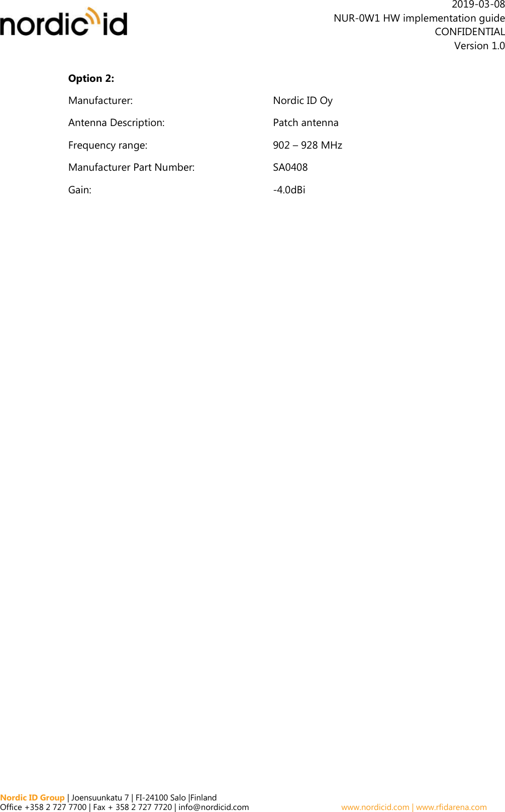
![Nordic ID Group | Joensuunkatu 7 | FI-24100 Salo |Finland Office +358 2 727 7700 | Fax + 358 2 727 7720 | info@nordicid.com www.nordicid.com | www.rfidarena.com 2019-03-08 NUR-0W1 HW implementation guide CONFIDENTIAL Version 1.0 Português [Portuguese] [Nordic ID] declara que este [RFID Radio module NUR-0W1] está conforme com os requisitos essenciais e outras disposições da Directiva 2014/53/EU. Slovensko [Slovenian] [Nordic ID] izjavlja, da je ta [RFID Radio module NUR-0W1] v skladu z bistvenimi zahtevami in ostalimi relevantnimi določili direktive 2014/53/ES. Slovensky [Slovak] [Nordic ID] týmto vyhlasuje, že [RFID Radio module NUR-0W1] spĺňa základné požiadavky a všetky príslušné ustanovenia Smernice 2014/53/ES. Suomi [Finnish] [Nordic ID] vakuuttaa täten että [RFID Radio module NUR-0W1] on direktiivin 2014/53/EY oleellisten vaatimusten ja sitä koskevien direktiivin muiden ehtojen mukainen. Svenska [Swedish] Härmed intygar [Nordic ID] att denna [RFID Radio module NUR-0W1] står i överensstämmelse med de väsentliga egenskapskrav och övriga relevanta bestämmelser som framgår av direktiv 2014/53/EG. LABELING REQUIREMENTS The 'CE' marking must be in a visible area on the OEM product. APPROVED ANTENNAS Maximum allowed ERP power is 33dBm. NUR-0W1 has maximum output power of 20dBm. Meaning that 15dBi is the maximum allowed antenna gain without cable losses. Formula how to calculate maximum allowed antenna gain:](https://usermanual.wiki/Nordic-ID/NUR0W1.Hardware-implementation-guide/User-Guide-4195545-Page-25.png)
![Nordic ID Group | Joensuunkatu 7 | FI-24100 Salo |Finland Office +358 2 727 7700 | Fax + 358 2 727 7720 | info@nordicid.com www.nordicid.com | www.rfidarena.com 2019-03-08 NUR-0W1 HW implementation guide CONFIDENTIAL Version 1.0 20 dBm – 2.15 (dipole gain) + [antenna gain dBi] – [cable attenuation dB] < 33dBm Beamwidth restrictions: For transmissions ≤500 mW e.r.p. there shall be no restriction on beam width. For transmissions of > 500 mW e.r.p. to ≤ 1 000 mW e.r.p. beam widths shall be ≤ 180º For transmissions of > 1 000 mW e.r.p. to 2 000 mW e.r.p. beam widths shall be ≤ 90º 11.2. FCC This equipment has been tested and found to comply with the limits for a Class B digital device, pursuant to Part 15 of the FCC Rules. These limits are designed to provide reasonable protection against harmful interference in a residential installation. This equipment generates and can radiate radio frequency energy and, if not installed and used in accordance with the instructions, may cause harmful interference to radio communications. However, there is no guarantee that interference will not occur in a particular installation. If this equipment does cause harmful interference to radio or television reception, which can be determined by turning the equipment off and on, the user is encouraged to try to correct the interference by one of the following measures: Reorient or relocate the receiving antenna. Increase the separation between the equipment and receiver. Connect the equipment into an outlet on a circuit different from that to which the receiver is connected. Consult the dealer or an experienced radio/TV technician for help. This device complies with Part 15 of the FCC Rules. Operation is subject to the following two conditions: (1) This device may not cause harmful interference, and (2) this device must accept any interference received, including interference that may cause undesired operation. Note: User of the module cannot change the region setting of the module. When FCC region is set, the module operates in frequency band of 902 – 928Mhz. FCC Caution: Any changes or modifications not expressly approved by the party responsible for compliance could void the user's authority to operate this equipment. This NUR-0W1 transmitter module is authorized to be used in other devices only by OEM Integrators under the following conditions:](https://usermanual.wiki/Nordic-ID/NUR0W1.Hardware-implementation-guide/User-Guide-4195545-Page-26.png)