Nordic ID NUR0W1 Nordic ID UHF RFID Radio module NUR-0W1 User Manual Hardware implementation guide
Nordic ID Oy Nordic ID UHF RFID Radio module NUR-0W1 Hardware implementation guide
Contents
- 1. Hardware implementation guide
- 2. RF Safety Training Leaflet
- 3. Data Sheet
- 4. Quick Guide
Hardware implementation guide
Nordic ID Group | Joensuunkatu 7 | FI-24100 Salo |Finland
Office +358 2 727 7700 | Fax + 358 2 727 7720 | info@nordicid.com www.nordicid.com | www.rfidarena.com
2019-03-08
NUR-0W1 HW implementation guide
CONFIDENTIAL
Version 1.0
NUR-0W1
HW IMPLEMENTATION GUIDE

Nordic ID Group | Joensuunkatu 7 | FI-24100 Salo |Finland
Office +358 2 727 7700 | Fax + 358 2 727 7720 | info@nordicid.com www.nordicid.com | www.rfidarena.com
2019-03-08
NUR-0W1 HW implementation guide
CONFIDENTIAL
Version 1.0
CONTENTS
1. GENERAL DESCRIPTION ...................................................................................................................................................................... 4
1.1. KEY FEATURES ..................................................................................................................................................................... 4
1.2. BLOCK DIAGRAM ............................................................................................................................................................... 4
1.3. TYPICAL APPLICATION SCHEMATICS ......................................................................................................................... 5
2. ELECTRICAL CHARACTERISTICS ....................................................................................................................................................... 5
2.1. ABSOLUTE MAXIMUM RATINGS .................................................................................................................................. 6
2.2. DC CHARACTERISTICS ...................................................................................................................................................... 6
2.3. RF CHARACTERISTICS ....................................................................................................................................................... 6
2.4. PERFORMANCE CHARACTERISTICS ............................................................................................................................ 7
3. PIN ASSIGNMENTS ................................................................................................................................................................................ 7
3.1. PIN DESIGNATION ............................................................................................................................................................. 7
3.2. PIN MAPPING ...................................................................................................................................................................... 8
3.3. SIGNAL DESCRIPTIONS .................................................................................................................................................... 9
4. OEM DESIGN CONSIDERATIONS ................................................................................................................................................. 11
4.1. RF-OUTPUT AND ANTENNA REQUIREMENTS .................................................................................................... 11
4.1.1. ANTENNA CONSIDERATIONS .................................................................................................................... 11
4.1.2. LAYOUT RECOMMENDATIONS ................................................................................................................. 11
4.1.3. TRANSMISSION LINE ..................................................................................................................................... 11
4.2. POWER SUPPLY ................................................................................................................................................................ 12
4.3. USB DEVICE PORT ........................................................................................................................................................... 12
4.4. GPIOS ................................................................................................................................................................................... 12
5. RF-PARAMETERS ................................................................................................................................................................................. 12
5.1. TX-LEVEL ............................................................................................................................................................................. 12
5.2. RECEIVER SENSITIVITY ................................................................................................................................................... 13
5.3. RF-PROFILE ........................................................................................................................................................................ 13
5.4. REGION ................................................................................................................................................................................ 13
6. RFID INVENTORY PARAMETERS ................................................................................................................................................... 13
6.1. Q-VALUE ............................................................................................................................................................................. 14
6.2. SESSION .............................................................................................................................................................................. 14
6.3. ROUNDS ............................................................................................................................................................................. 15
6.4. SELECTING RIGHT PARAMETERS .............................................................................................................................. 15
6.5. RSSI-FILTERS ...................................................................................................................................................................... 15
6.6. DYNAMIC POWER SAVE MODE ................................................................................................................................ 16
7. GPIO CONFIGURATIONS ................................................................................................................................................................. 16
8. DIAGNOSTIC FUNCTIONS ............................................................................................................................................................... 16

Nordic ID Group | Joensuunkatu 7 | FI-24100 Salo |Finland
Office +358 2 727 7700 | Fax + 358 2 727 7720 | info@nordicid.com www.nordicid.com | www.rfidarena.com
2019-03-08
NUR-0W1 HW implementation guide
CONFIDENTIAL
Version 1.0
8.1. CHANNEL SCANNER ...................................................................................................................................................... 17
8.2. REFLECTED POWER MEASUREMENT ....................................................................................................................... 17
8.3. RECEIVED SIGNAL STRENGTH INDICATOR (RSSI) .............................................................................................. 17
9. DIMENSIONS ........................................................................................................................................................................................ 17
9.1. MECHANICAL DIMENSION ......................................................................................................................................... 17
9.2. LAND PATTERN ................................................................................................................................................................ 18
10.
SMT ASSEMBLY PROCESS AND THERMAL PROCESSING ................................................................................................... 19
10.1. STORAGE CONDITIONS ........................................................................................................................................... 19
10.2. SOLDERING PROCESS ............................................................................................................................................... 20
11.
REGULATORY INFORMATION ........................................................................................................................................................ 21
11.1. EUROPEAN UNION AND EFTA COUNTRIES ..................................................................................................... 22
11.2. FCC .................................................................................................................................................................................... 26
11.3. ISED .................................................................................................................................................................................. 28
11.4. ISED .................................................................................................................................................................................. 30
12.
ABOUT NORDIC ID ............................................................................................................................................................................. 33
13.
VERSION HISTORY .............................................................................................................................................................................. 33

Nordic ID Group | Joensuunkatu 7 | FI-24100 Salo |Finland
Office +358 2 727 7700 | Fax + 358 2 727 7720 | info@nordicid.com www.nordicid.com | www.rfidarena.com
2019-03-08
NUR-0W1 HW implementation guide
CONFIDENTIAL
Version 1.0
1. GENERAL DESCRIPTION
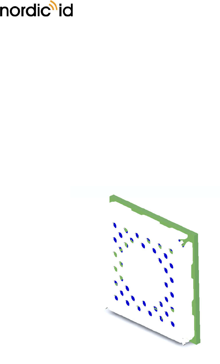
NUR-0W1 is an extremely small UHF RFID module with a footprint of 15 x 15mm. It is compatible with
ISO18000-63 (EPC C1G2) standard providing all basic functionalities like inventory, read, write, access,
lock, kill. Module fulfils ETSI, FCC and ISED radio regulations. It is also compatible with DRM (dense
reader mode) requirements. Maximum output power is 20dBm and it can be adjusted via SW API with
1 dB steps. Module is aimed to be embedded into small sized UHF RFID end-products. It is also perfect
choice for battery operated devices as module consumes very small amount of power compared to
other UHF RFID reader modules available.
1.1. KEY FEATURES
• SMT compatible module with extremely small footprint
• ISO 18000-63 (EPC C1G2) full protocol support + custom commands
• Low power consumption with high noise rejection due to on-board voltage regulators
• DRM compatible
• Freely adjustable RF and inventory parameters
• Approved by ETSI, FCC and ISED telecommunication organizations
• UART and USB 2.0 communication
• 8 programmable GPIO with event trigger
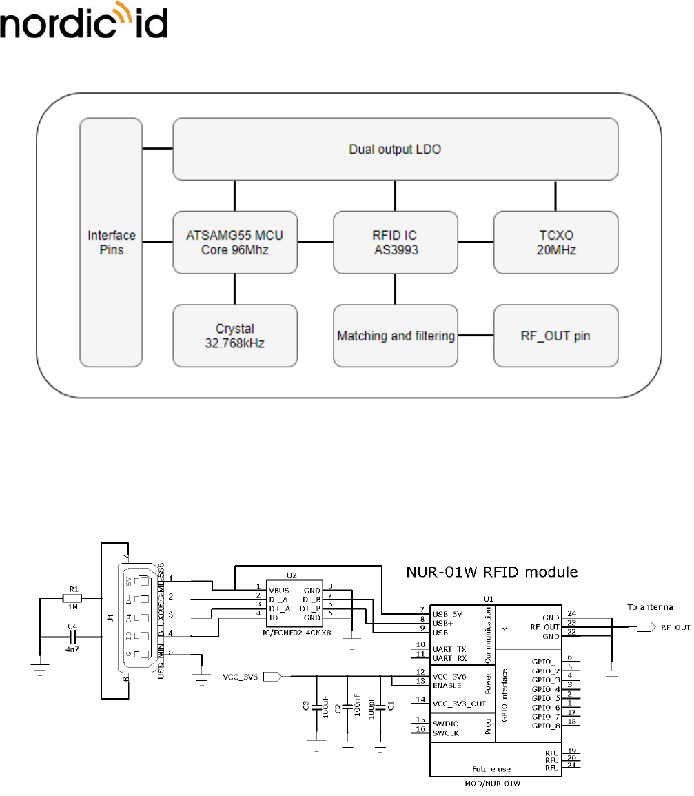
1.2. BLOCK DIAGRAM
Nordic ID Group | Joensuunkatu 7 | FI-24100 Salo |Finland
Office +358 2 727 7700 | Fax + 358 2 727 7720 | info@nordicid.com www.nordicid.com | www.rfidarena.com
2019-03-08
NUR-0W1 HW implementation guide
CONFIDENTIAL
Version 1.0
Figure 1. Block diagram of the NUR-0W1 module.
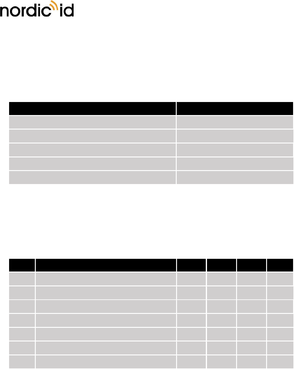
1.3. TYPICAL APPLICATION SCHEMATICS
Figure 2. Typical application schematic.
2. ELECTRICAL CHARACTERISTICS
Section provides information about the DC, RF and performance characteristics of the NUR-0W1 module.
Nordic ID Group | Joensuunkatu 7 | FI-24100 Salo |Finland
Office +358 2 727 7700 | Fax + 358 2 727 7720 | info@nordicid.com www.nordicid.com | www.rfidarena.com
2019-03-08
NUR-0W1 HW implementation guide
CONFIDENTIAL
Version 1.0
2.1. ABSOLUTE MAXIMUM RATINGS
Violating these values may cause damage to the module. Also, correct operation is not guaranteed if
operating outside these values. NUR-0W1 is ESD sensitive component so it must be handled with care.
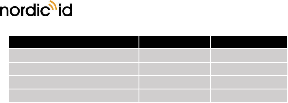
Table 1. DC characteristics (VCC_3V6 = 3.6V @ +25°C).
Absolute maximum ratings Value
Operation ambient temperature -20°C to +55°C
Storage temperature (package unopened) -30°C to +85°C
Supply and enable voltage +7.0V
Maximum GPIO pin voltage +4.0V
Other pins +4.0V
2.2. DC CHARACTERISTICS
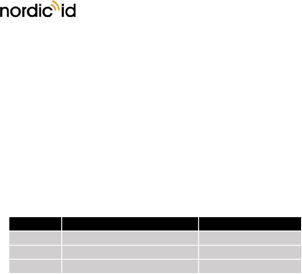
Table 2. DC characteristics (VCC_3V6 = 3.6V @ +25°C).
Symbol
Parameter Min Typical Max Units
Vext Supply voltage range 3.5 3.6 5.5 V
Iext Maximum supply current 280 310 350 mA
Isource Maximum GPIO source current - - 4 mA
Isink Maximum GPIO sink current - - 4 mA
Vlow GPIO input low-level voltage - - 0.8 V
Vhigh GPIO input high-level voltage 2.0 - - V
Ven Module enable voltage 1.2 - Supply V
2.3. RF CHARACTERISTICS
Nordic ID Group | Joensuunkatu 7 | FI-24100 Salo |Finland
Office +358 2 727 7700 | Fax + 358 2 727 7720 | info@nordicid.com www.nordicid.com | www.rfidarena.com
2019-03-08
NUR-0W1 HW implementation guide
CONFIDENTIAL
Version 1.0
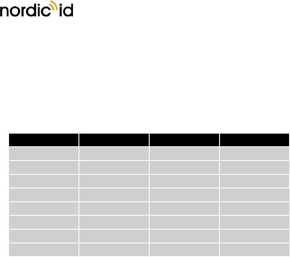
Table 3. RF characteristics (VCC_3V6 = 3.6V @ +25°C).
Symbol
Parameter Min Typical Max Units
Sens Receiver sensitivity (RF port of the module) - - -70dBm dBm
Pout Maximum RF output power 18 19 20 dBm
Padj Power adjustment step - 1 - dB
S11 Reflection attenuation for antenna 10 - - dB
DRT Reader-to-tag data rate TBD TBD TBD kbps
DTR Tag-to-reader data rate TBD TBD TBD kbps
2.4. PERFORMANCE CHARACTERISTICS
The performance of the module is highly dependent on the test environment, reader antenna and tag
performance. Interferences from other radio sources operating in the same frequency may decrease the
performance. Also, the tag antenna and the tag IC may have significant effect on the values presented
below. Selected RF and inventory parameters do have a big influence to reading performance as well.
Table 4. Performance characteristics (VCC_3V6 = 3.6V @ +25°C).
Symbol
Parameter Min Typical Max Units
Rdist Reading distance with 5dBi antenna (Belt R6) 2 m
Rrate Read rate (High speed) 500 tags/s
Tamb Operation ambient temperature -20 - +55 °C
Hrel Relative humidity 10 - 95 %
3. PIN ASSIGNMENTS
This section provides information about the different signals available from NUR-0W1 module and how
they are mapped to physical pads of the component.
3.1. PIN DESIGNATION
Nordic ID Group | Joensuunkatu 7 | FI-24100 Salo |Finland
Office +358 2 727 7700 | Fax + 358 2 727 7720 | info@nordicid.com www.nordicid.com | www.rfidarena.com
2019-03-08
NUR-0W1 HW implementation guide
CONFIDENTIAL
Version 1.0
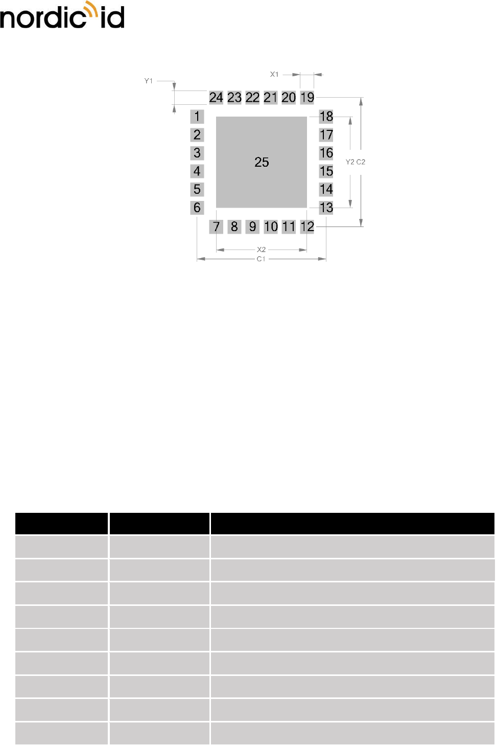
Figure 3. Pin numbering (top thru view).
3.2. PIN MAPPING
Below table provides pin-to-signal mapping information.
Table 5. Signal descriptions.
Pin number Signal name Pin type
1 GPIO_6 Bidirectional
2 GPIO_5 Bidirectional
3 GPIO_4 Bidirectional
4 GPIO_3 Bidirectional
5 GPIO_2 Bidirectional
6 GPIO_1 Bidirectional
7 USB_5V Input (USB detection)
8 USB+ Bidirectional (USB data plus)
9 USB- Bidirectional (USB data minus)
Nordic ID Group | Joensuunkatu 7 | FI-24100 Salo |Finland
Office +358 2 727 7700 | Fax + 358 2 727 7720 | info@nordicid.com www.nordicid.com | www.rfidarena.com
2019-03-08
NUR-0W1 HW implementation guide
CONFIDENTIAL
Version 1.0
10 UART_TX Output
11 UART_RX Input.
12 VCC_3V6 Supply input
13 ENABLE Input
14 VCC_3V3_OUT Supply output
15 SWDIO Bidirectional
16 SWCLK Input
17 GPIO_7 Bidirectional
18 GPIO_8 Bidirectional
19 RFU NC
20 RFU NC
21 RFU RF Input (Monostatic configuration)
22 GND Supply
23 RF_OUT Bidirectional
24 GND Supply
25 Thermal pad Supply
3.3. SIGNAL DESCRIPTIONS
Below table provides descriptions for NUR-0W1 module signals.
Table 6. Signal descriptions.
Signal name Pin number(s) Description
USB+ 8 This pin is used as USB data plus device port. It is advised to
use external ESD protection component if connected to user
accessible USB connector.
USB- 9 This pin is used as USB data minus device port. It is advised
to use external ESD protection component if connected to
user accessible USB connector.
USB_5V 7 This pin is only used for USB connection detection. It is
advised to use external ESD protection component if
Nordic ID Group | Joensuunkatu 7 | FI-24100 Salo |Finland
Office +358 2 727 7700 | Fax + 358 2 727 7720 | info@nordicid.com www.nordicid.com | www.rfidarena.com
2019-03-08
NUR-0W1 HW implementation guide
CONFIDENTIAL
Version 1.0
connected to user accessible USB connector. Current is not
drawn from this input pin.
UART_TX 10 This pin is used for module UART output signal. Logic level is
3.3V. If UART is used for communication the pin should be
connected to the Host MCU UART RX port.
UART_RX 11 This pin is used for module UART input signal. Logic level is
3.3V. If UART is used for communication the pin should be
connected to the Host MCU UART TX port.
VCC_3V6 12 This pin is used for power supply input for NUR-0W1 module.
It is recommended to use 100µF (low ESR) 100nF and 100pF
capacitor near the VCC_3V6_IN input pin to maintain stable
operating voltage for the reader module.
ENABLE 13 Driving this pin to high will enable the NUR-0W1 module. It
is internally connected to onboard voltage regulator’s enable
input. The trigger level is 1.2V and the reader module will
wake up in 1.5s. If the external power switch is used to toggle
ON and OFF, this pin can be connected directly to
VCC_3V6_IN.
VCC_3V3_OUT 14 This pin is connected to internal power regulator output. The
pin is used for production testing and it should not be used.
SWDIO 15 For production purposes. Do not use.
SWCLK 16 For production purposes. Do not use.
RFU 19,20,21 These pins are reserved for future use. Do not connect these
pins.
GPIO_x 1,2,3,4,5,6,17,18 These pins are used as general-purpose IOs. They can be
configured via SW API as input or output ports. IO voltage
level is 3.3V. GPIOs have source current capability of 4mA and
sink current capability of 4mA.
RF_OUT 23 50Ω impedance RF output / input pin. Trace to/from this pin
should be also matched to 50 Ω. See more details from the
design considerations section.
GND 22,14, These pins are used for grounding and to improve the
thermal performance. They should be connected to Host
board GND net.
Thermal 25 These pins are used for grounding and to improve the
thermal performance. They should be connected to Host
board GND net.
Nordic ID Group | Joensuunkatu 7 | FI-24100 Salo |Finland
Office +358 2 727 7700 | Fax + 358 2 727 7720 | info@nordicid.com www.nordicid.com | www.rfidarena.com
2019-03-08
NUR-0W1 HW implementation guide
CONFIDENTIAL
Version 1.0
4. OEM DESIGN CONSIDERATIONS
When integrating the NUR-0W1 module into host board you need to follow the below recommendations
to obtain proper operation of the module.
4.1. RF-OUTPUT AND ANTENNA REQUIREMENTS
For UHF RFID module it is very important that good RF design practices are used. Unlike conventional
radios, transmission and receiving are on at the same time without significant frequency separation. This
leads to situation where systems reflective power coming back to modules RF pin will decrease the
performance of the module. Less reflective power means better performance and vice versa.
4.1.1. ANTENNA CONSIDERATIONS
Like stated earlier, minimising the reflective power is the key to good performance. Main source for this
power is antenna having a poor S11 (reflection attenuation) value. If matching of the antenna is poor,
significant part of the RF power will not radiate but instead will reflect to the module. Antenna should have
S11 value equal or better than 10dB.
4.1.2. LAYOUT RECOMMENDATIONS
RF output must be routed using 50ohm transmission line (see section 4.1.3). If proper RF design guidelines
are not used it might lead to decrease of output power, sensitivity and cause mask violations.
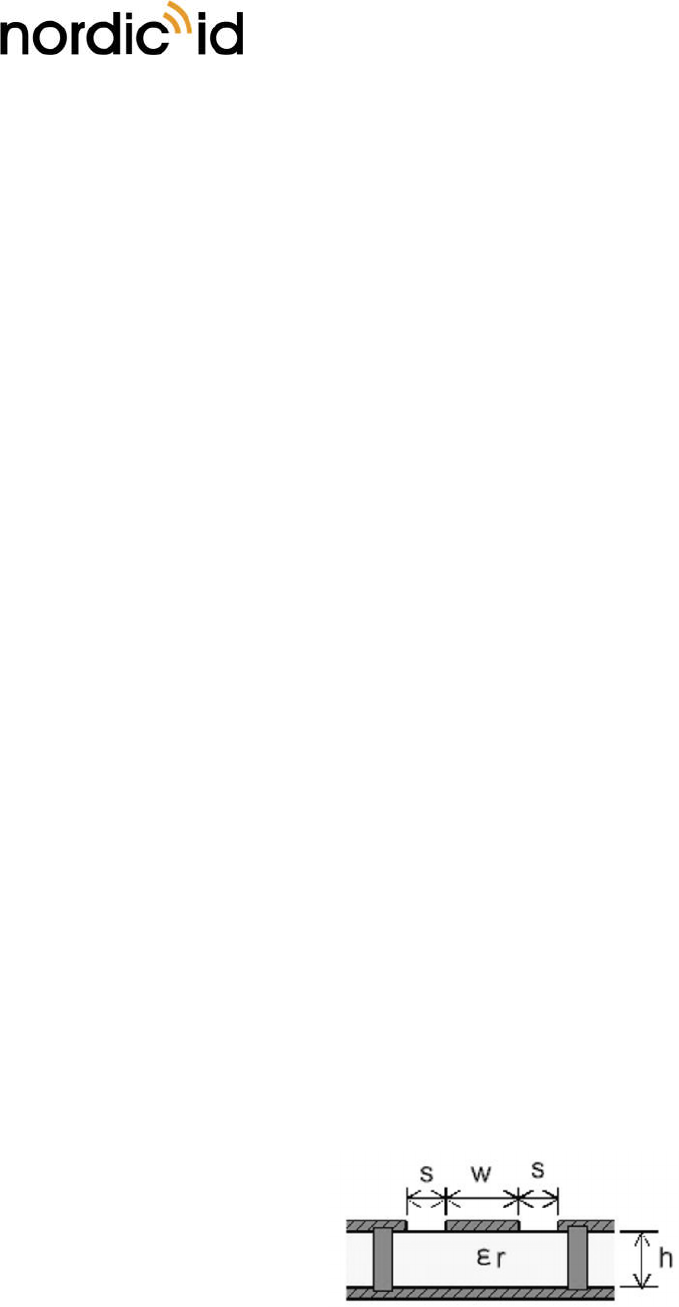
4.1.3. TRANSMISSION LINE
The RF signal from the module is routed to antenna connector using a grounded CPW structure. This is to
achieve the maximum isolation and RF shielding to RF lines. Also, grounding bias should be added along
the line to give additional shielding.
Figure 4. Grounded CPW with via stitching.
Table 7. Recommended PCB values for 4-layer board (L2 is the GND plane for transmission line)
Nordic ID Group | Joensuunkatu 7 | FI-24100 Salo |Finland
Office +358 2 727 7700 | Fax + 358 2 727 7720 | info@nordicid.com www.nordicid.com | www.rfidarena.com
2019-03-08
NUR-0W1 HW implementation guide
CONFIDENTIAL
Version 1.0
Profile Value Units
W 0.35 mm
S 0.2 mm
H 0.18 mm
Er 4
4.2. POWER SUPPLY
The NUR-0W1 has internal linear power regulators for getting better power supply noise rejection.
However, it is still important to supply low noise and stable power to the module. The voltage ripple should
be kept under 200mVpp and it is recommended to add a minimum of 100µF low ESR, 100nF and 100pF
capacitors next to the VCC_3V6_IN pin.
VCC_3V3_OUT is internal regulator output and it is used for production testing purposes. This pin should
not be used to power external circuits.
4.3. USB DEVICE PORT
USB+, USB- and USB_5V pins are used to provide 2.0 compliant USB device port. It is advised to use external
ESD protection component if connected to user accessible USB connector. Please the section 1.3 for typical
USB connection schematics.
4.4. GPIOS
TBD
5. RF-PARAMETERS
By adjusting the RF parameters, it is possible to optimize the modules RF performance for different
environments and use cases.
5.1. TX-LEVEL
The maximum TX output power level is 20dBm (100mW). The power can be adjusted by 1dB steps. In total,
there are 19 steps meaning the minimum output power value is 1dBm. If your implementation uses more
Nordic ID Group | Joensuunkatu 7 | FI-24100 Salo |Finland
Office +358 2 727 7700 | Fax + 358 2 727 7720 | info@nordicid.com www.nordicid.com | www.rfidarena.com
2019-03-08
NUR-0W1 HW implementation guide
CONFIDENTIAL
Version 1.0
than 1 antenna and antenna switch is controlled by NUR-0W1 antenna control -functions, you can set
individual per antenna TX power levels. Refer to API documentation for more information.
5.2. RECEIVER SENSITIVITY
The sensitivity of the receiver can be adjusted by three steps. Low, Nominal and High with 10dB step sizes.
By default, the Nominal setting is used.
5.3. RF-PROFILE
There are 3 different RF profiles which can be selected. Robust, Nominal and High speed. Robust offers the
best sensitivity and tolerance for interferences but read rate also is the slowest. By default, Nominal is used.
It is a compromise between Robust and High speed which offers the fastest read rate but is prone to
interferences.
Table 8. Available RF profiles.
Profile R T and T R parameters used Read rate up to
Robust TBD TBD
Nominal TBD TBD
High speed TBD TBD
5.4. REGION
The NUR-0W1 has pre-defined region settings defining frequency and channel sets for operating under
different radio regulations. Globally the regulations vary depending on the country or part of the world.
Refer to API documentation for list of pre-defined countries. Thru SW API you are also able to generate a
custom hop table if needed. When module ships from production it is locked to pre-selected region setting.
Contact Nordic ID support for more information.
6. RFID INVENTORY PARAMETERS
By selecting the proper RFID inventory parameters, you can optimize the modules reading performance for
different tag populations and use cases.
Nordic ID Group | Joensuunkatu 7 | FI-24100 Salo |Finland
Office +358 2 727 7700 | Fax + 358 2 727 7720 | info@nordicid.com www.nordicid.com | www.rfidarena.com
2019-03-08
NUR-0W1 HW implementation guide
CONFIDENTIAL
Version 1.0
6.1. Q-VALUE
The Q-value defines the amount of open response slots that tags can use per one inventory round. Number
of slots can be calculated by formula 2Q. It is advised to use twice as much slots compared to amount of
tags that you have in your readers reading field simultaneously. Selectable values are 0 – 15 and value 0
means automatic Q-value adjustment. When q value of 0 is used, reader will automatically increase the Q-
value when lots of collisions are noticed and decreased the value when there are only few collisions. By
default, the Q-value is set to 0.
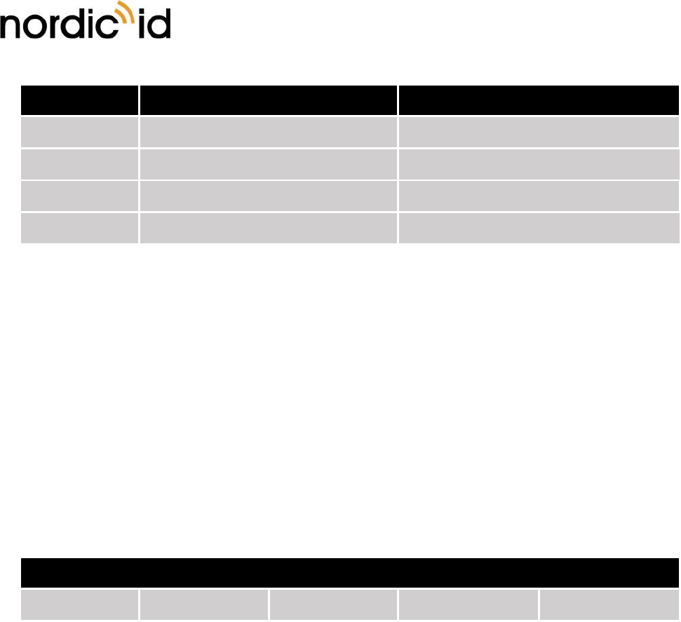
Table 9. Relation between the Q value and the number of response slots for round.
Q-value Response slots Q-value Response slots
0 Automatic 8 256
1 2 9 512
2 4 10 1024
3 8 11 2048
4 16 12 4096
5 32 13 8192
6 64 14 16384
7 128 15 32768
6.2. SESSION
There are four session options which you can use when initializing inventory round. Every session has two
target states A and B. By default, Gen2 tags are at state A if tag has not been read recently. When tag is
read it flips to state B and doesn’t reply to readers query made using target state A. The table below
describes the persistence of tag’s state machine when using different session values. For example, when
using session 0 the tag will come back to state A immediately when tag power is lost. Usually tag loses the
power when reader stops the inventory round or chances the channel. Persistence when tag power is ON
is not defined by the ISO18000-6C when using session settings S0, S2 and S3. With session 1 the tag will
keep it state over 500ms but less than 5s. With session values 2 and 3 tags will keep it states over 2s when
tag power is lost. Time can vary depending what tag IC is used.
Table 10. Persistence characteristics of gen2 tags.
Nordic ID Group | Joensuunkatu 7 | FI-24100 Salo |Finland
Office +358 2 727 7700 | Fax + 358 2 727 7720 | info@nordicid.com www.nordicid.com | www.rfidarena.com
2019-03-08
NUR-0W1 HW implementation guide
CONFIDENTIAL
Version 1.0
Session flag Persistence: Tag power ON Persistence: Tag power OFF
S0 Indefinite None
S1 500ms < t < 5s 500ms < t < 5s
S2 Indefinite t > 2s
S3 Indefinite t > 2s
6.3. ROUNDS
The rounds setting defines how many query rounds is done inside one inventory round. After every
inventory round the reader will send data to the Host. Selectable values are 0 – 10. Zero meaning automatic
rounds adjustment. The automatic adjustment decides after every query round whether another round is
necessary based on the number of data collisions. By default, rounds setting is set to 0. This setting can
help the reader to find all the tags that are in the readers reading field when using session 0. Because tags
that are found in query round 1 doesn’t replay in the following query rounds. When using session 1/2/3
this does not make any significant difference because tags that are read are quiet anyway.
Table 11. Relation between inventory round and query round.
Inventory round
Query round 1 Query round 2 Query round 3 … Query round 10
6.4. SELECTING RIGHT PARAMETERS
TBD
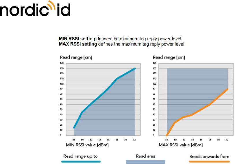
6.5. RSSI-FILTERS
NUR-0W1 module has internal RSSI filters which can be used to limit the read area. By applying the filters,
you can set the limits which tag replay must met to be registered. MIN RSSI –value means that tag replay
signal needs to be equal or stronger then the defined value. Otherwise tag is not read. MAX RSSI value in
other hand means that signal strength must be lower than the filter value. There are separate RSSI filter
values for inventory, read and write operations. These can be set individually.
Nordic ID Group | Joensuunkatu 7 | FI-24100 Salo |Finland
Office +358 2 727 7700 | Fax + 358 2 727 7720 | info@nordicid.com www.nordicid.com | www.rfidarena.com
2019-03-08
NUR-0W1 HW implementation guide
CONFIDENTIAL
Version 1.0
Figure 5. Read range limited by the RSSI filter (100mW TX power level and 0dBi antenna gain used).
6.6. DYNAMIC POWER SAVE MODE
NUR-0W1 module has power save modes which can be enabled via SW API. By default, the power save is
ON with depth of 100ms. Other depths are 500ms and 1000ms. The power save mode works in a way that
when module reads continuously (applies only when using inventory stream -command) it goes to sleep if
there are no tags in the field. The sleep time is defined by the depth value. After the sleep period is elapsed
module starts to read again and so on. If there are one or more tags in the field the module will not go into
sleep
7. GPIO CONFIGURATIONS
All GPIOs can be configured via SW API to be inputs or outputs. IO voltage level is 3.3V and maximum
source current is 4mA and sink current 4mA. When configured as input SW API can check what the state
(high / low) of the GPIO pin is. Also, event is generated from the state change. When GPIO is configured as
an output the SW API can drive the GPIO pin to high or low.
8. DIAGNOSTIC FUNCTIONS
Using diagnostic functionalities like channel channer, reflected power measurement and received signal
level indicator you can examine the proper operation of the module.

Nordic ID Group | Joensuunkatu 7 | FI-24100 Salo |Finland
Office +358 2 727 7700 | Fax + 358 2 727 7720 | info@nordicid.com www.nordicid.com | www.rfidarena.com
2019-03-08
NUR-0W1 HW implementation guide
CONFIDENTIAL
Version 1.0
8.1. CHANNEL SCANNER
TBD
8.2. REFLECTED POWER MEASUREMENT
This measurement can be used to check what is the matching of the antenna(s) and feed line(s). When this
function is triggered will NUR-0W1 module set a carrier wave ON at full power and then measure the power
level which is coming to receiver port. To transform the returned value into absolute power level coming in
to modules RF-pin, you need to add 13 to the obtained value. Using this functionality, you can verify is the
antenna connected and what is the frequency where the best matching of the antenna is located.
8.3. RECEIVED SIGNAL STRENGTH INDICATOR (RSSI)
When reading a tag NUR-0W1 module also returns received signal strength indication values. Two values
are returned per one tag. One is the absolute power level (dBm) and second is the scaled RSSI value of the
tags backscatter signal. Scaled RSSI value returned is between 0 – 100. 0 being the minimum signal level
the module can receive and 100 as a maximum.
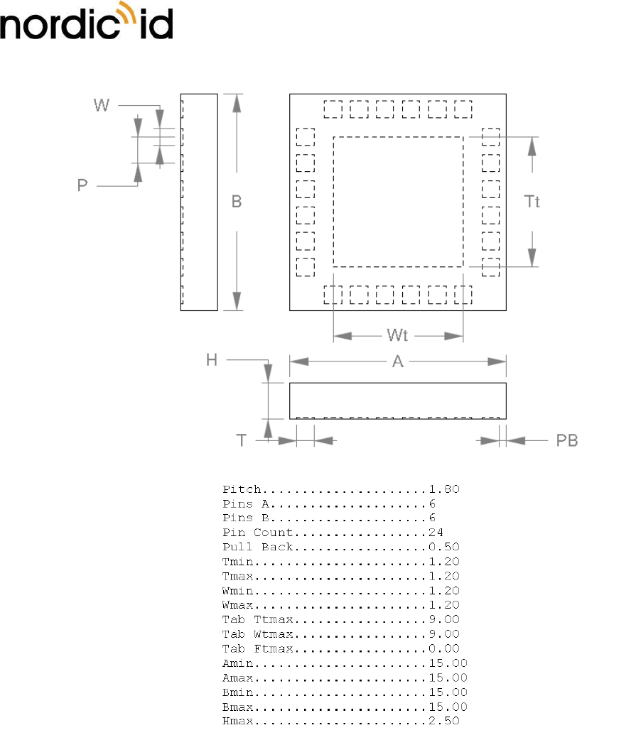
9. DIMENSIONS
Mechanical dimension and land pattern of the NUR-0W1 module.
9.1. MECHANICAL DIMENSION
Nordic ID Group | Joensuunkatu 7 | FI-24100 Salo |Finland
Office +358 2 727 7700 | Fax + 358 2 727 7720 | info@nordicid.com www.nordicid.com | www.rfidarena.com
2019-03-08
NUR-0W1 HW implementation guide
CONFIDENTIAL
Version 1.0
Unit mm
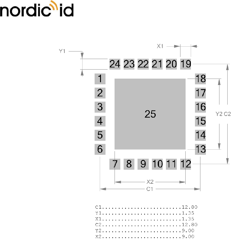
9.2. LAND PATTERN
Nordic ID Group | Joensuunkatu 7 | FI-24100 Salo |Finland
Office +358 2 727 7700 | Fax + 358 2 727 7720 | info@nordicid.com www.nordicid.com | www.rfidarena.com
2019-03-08
NUR-0W1 HW implementation guide
CONFIDENTIAL
Version 1.0
Unit mm
10. SMT ASSEMBLY PROCESS AND THERMAL PROCESSING
NUR-0W1 module contains single sided assembly of SMT components reflow-soldered on multilayer HDI
(high density interconnections) glass-fiber re-enforced epoxy printed board. The bottom side terminations
are ENIG (NiP/Au) plated. Soldering alloy used for attaching module components is eutectic SnAgCu.
Module internal components soldering has been optimized for minimal thermal stress.
NUR-0W1 modules shall be delivered in a special tray packing to protect modules against mechanical, ESD
and moisture related stresses. Due to high density interconnections technology, module total water content
must be below 0.1%-w prior to any thermal processing above water boiling point.
The board assembly process of NUR module on motherboard will introduce re-flow of module components.
Thus, to avoid degradation of solder joint interfaces, the module must be stored and soldered according
to the guidelines given below.
10.1. STORAGE CONDITIONS
Long-term storage conditions

Nordic ID Group | Joensuunkatu 7 | FI-24100 Salo |Finland
Office +358 2 727 7700 | Fax + 358 2 727 7720 | info@nordicid.com www.nordicid.com | www.rfidarena.com
2019-03-08
NUR-0W1 HW implementation guide
CONFIDENTIAL
Version 1.0
Temperature +15…+27°C (optimal)
Temperature gradient max. 2°C/hour
Relative humidity < 15% within specified temperature range
Opened and broken packages must be re-sealed. If open time (floor life out of pack) has been exceeded,
or moisture content detected, modules must be baked prior to re-sealing vacuum pack.
Short-term storage conditions (typically same as production environment)
Temperature +20…+27°C
Temperature gradient max. 2°C/hour
Temperature gradient < 15% within specified temperature range
Modules may be stored in a dry cabinet without protective packing according to IPC/JEDEC J-STD-033B.1,
table 7-1.
MSL level and open time
MSL level 5
Open time (floor life out of the bag) 48h
10.2. SOLDERING PROCESS
Boundary conditions
Acceptable soldering methods Convection reflow in air or nitrogen atmosphere
Condensation reflow soldering (vapor phase)
Recommended stencil thickness 125um ±10um
Pad design on motherboard See recommended pad pattern
Stencil openings TBD
Recommended solder alloy SnAg3.8±0.2Cu0.7±0.2
Note! If using under-eutectic solder alloys, such as
SAC305, it may be necessary to increase reflow
peak temperature by 5-10°C, due to higher mp. and
lower fluidity of non-eutectic SnAgCu alloys. This
Nordic ID Group | Joensuunkatu 7 | FI-24100 Salo |Finland
Office +358 2 727 7700 | Fax + 358 2 727 7720 | info@nordicid.com www.nordicid.com | www.rfidarena.com
2019-03-08
NUR-0W1 HW implementation guide
CONFIDENTIAL
Version 1.0
will increase thermal stress to module and
motherboard greatly.
Convection reflow oven heater configuration Double sided heating required in reflow,
recommended in preheating zones.
Maximum absorbed moisture content prior to
thermal processing
0.1%-w (Test method IPC-TM-650, 2.6.28)
Moisture content and/or moisture absorption rate,
Printed Board
Recommended moisture reduction condition +60°C/12h vacuum pack removed during drying,
re-seal after drying, unless modules will be used
within allowed open time after drying
Moisture and solvent contamination No moisture or solvent contamination allowed in
solder paste or on solderable surfaces
Recommended reflow conditions
Preheating phase -max. duration 180s
-end temperature 190-200°C
-delta T on assembly max. 10°C at end of
preheating
Soldering phase -total duration 190s
-max. time above 217°C (mp.) 30s
-Tpeak max. 235°C, measured at module bottom
-Tpeak max. 225°C, measured at motherboard
surface, under module
Cooling Two-stage, double sided cooling recommended
1st stage: 2-5°C/s cooling until melting point
2nd stage: 1-3°C/s after melting point
11. REGULATORY INFORMATION
When OEM prefers to leverage Nordic ID’s grants and certifications of the NUR-0W1 UHF RFID module, the
host device documentation shall include regulatory compliance information on the NUR-0W1 module.
Corresponding to the applicable regulatory agencies the following sections outline regulatory compliance
information needed in the user documentation and external labels for the host devices into which the NUR-
0W1 is integrated.

Nordic ID Group | Joensuunkatu 7 | FI-24100 Salo |Finland
Office +358 2 727 7700 | Fax + 358 2 727 7720 | info@nordicid.com www.nordicid.com | www.rfidarena.com
2019-03-08
NUR-0W1 HW implementation guide
CONFIDENTIAL
Version 1.0
When leveraging Nordic ID’s grants and certifications, antenna shall be considered in view of the fact that
the NUR-0W1 module has met the essential regulatory requirements with the antennas listed in the context
of particular regulatory compliance information (Approved Antennas). Using the antenna that is an
approved one, OEM integrator may demonstrate with less effort that the device with the integrated NUR-
0W1 module complies with the requirements.
11.1. EUROPEAN UNION AND EFTA COUNTRIES
USER GUIDE REQUIREMENTS
This apparatus complies the essential requirements of the Radio Equipment Directive (RED) 2014/53/EU. In
order to prove presumption of conformity with the essential requirements of the Radio Equipment Directive
(RED) 2014/53/EU, following requirements and test methods have been applied to the apparatus:
article 3.2: ETSI EN 302 208 v3.1.1
- Radio spectrum matters for Radio Frequency Identification (RFID) equipment operating in the
band 865 MHz to 868 MHz with power levels up to 2W
article 3.1b: ETSI EN 301 489-1 v2.2.0
- Common ElectroMagnetic Compatibility (EMC) requirements
article 3.1b: ETSI EN 301 489-3 v2.1.1
- Specific ElectroMagnetic Compatibility (EMC) conditions for Short-Range Devices (SRD)
operating on frequencies between 9 kHz and 246 GHz
article 3.1a: EN 60950-1:2006 + A1:2010 + A11:2009+A12:2011+ A2:2013
- General requirements for Safety of Information Technology Equipment
EN 62479: 2010
- Human exposure
EN 62311: 2008
- Human exposure limits
This apparatus complies EU Directive 2011/65/EU, Reduction of Hazardous Substances (RoHS).
Česky
[Czech]
[Nordic ID] tímto prohlašuje, že tento [RFID Radio module NUR-0W1] je ve shodě sezákladními požadavky
a dalšími příslušnými ustanoveními směrnice 2014/53/ES.

Nordic ID Group | Joensuunkatu 7 | FI-24100 Salo |Finland
Office +358 2 727 7700 | Fax + 358 2 727 7720 | info@nordicid.com www.nordicid.com | www.rfidarena.com
2019-03-08
NUR-0W1 HW implementation guide
CONFIDENTIAL
Version 1.0
Dansk
[Danish]
Undertegnede [Nordic ID] erklærer herved, at følgende udstyr [RFID Radio module NUR-0W1] overholder
de væsentlige krav og øvrige relevante krav i direktiv 2014/53/EF.
Deutsch
[German]
Hiermit erklärt [Nordic ID], dass sich das Gerät [RFID Radio module NUR-0W1] in Übereinstimmung mit den
grundlegenden Anforderungen und den übrigen einschlägigen Bestimmungen der Richtlinie 2014/53/EG
befindet.
Eesti
[Estonian]
Käesolevaga kinnitab [Nordic ID] seadme [RFID Radio module NUR-0W1] vastavust direktiivi 2014/53/EÜ
põhinõuetele ja nimetatud direktiivist tulenevatele teistele asjakohastele sätetele.
English
Hereby, [Nordic ID], declares that this [RFID Radio module NUR-0W1] complies with the essential
requirements and other relevant provisions of Directive 2014/53/EU.
Español
[Spanish]
Por medio de la presente [Nordic ID] declara que el [RFID Radio module NUR-0W1] cumple con los
requisitos esenciales y cualesquiera otras disposiciones aplicables o exigibles de la Directiva 2014/53/EU.
Ελληνική
[Greek]
ΜΕ ΤΗΝ ΠΑΡΟΥΣΑ [Nordic ID] ΔΗΛΩΝΕΙ ΟΤΙ [RFID Radio module NUR-0W1] ΣΥΜΜΟΡΦΩΝΕΤΑΙ ΠΡΟΣ ΤΙΣ
ΟΥΣΙΩΔΕΙΣ ΑΠΑΙΤΗΣΕΙΣ ΚΑΙ ΤΙΣ ΛΟΙΠΕΣ ΣΧΕΤΙΚΕΣ ΔΙΑΤΑΞΕΙΣ ΤΗΣ ΟΔΗΓΙΑΣ 2014/53/ΕΚ.
Français
[French]
Par la présente [Nordic ID] déclare que l'appareil [RFID Radio module NUR-0W1] est conforme aux
exigences essentielles et aux autres dispositions pertinentes de la directive 2014/53/EU.

Nordic ID Group | Joensuunkatu 7 | FI-24100 Salo |Finland
Office +358 2 727 7700 | Fax + 358 2 727 7720 | info@nordicid.com www.nordicid.com | www.rfidarena.com
2019-03-08
NUR-0W1 HW implementation guide
CONFIDENTIAL
Version 1.0
Italiano
[Italian]
Con la presente [Nordic ID] dichiara che questo [RFID Radio module NUR-0W1] è conforme ai requisiti
essenziali ed alle altre disposizioni pertinenti stabilite dalla direttiva 2014/53/EU.
Latviski
[Latvian]
Ar šo [Nordic ID] deklarē, ka [RFID Radio module NUR-0W1] atbilst Direktīvas 2014/53/EK būtiskajām
prasībām un citiem ar to saistītajiem noteikumiem.
Lietuvių
[Lithuanian]
Šiuo [Nordic ID] deklaruoja, kad šis [RFID Radio module NUR-0W1] atitinka esminius reikalavimus ir kitas
2014/53/EB Direktyvos nuostatas.
Nederlands
[Dutch]
Hierbij verklaart [Nordic ID] dat het toestel [RFID Radio module NUR-0W1] in overeenstemming is met de
essentiële eisen en de andere relevante bepalingen van richtlijn 2014/53/EG.
Malti
[Maltese]
Hawnhekk, [Nordic ID], jiddikjara li dan [RFID Radio module NUR-0W1] jikkonforma mal-ħtiġijiet essenzjali
u ma provvedimenti oħrajn relevanti li hemm fid-Dirrettiva 2014/53/EU.
Magyar
[Hungarian]
Alulírott, [Nordic ID] nyilatkozom, hogy a [RFID Radio module NUR-0W1] megfelel a vonatkozó alapvetõ
követelményeknek és az 2014/53/EU irányelv egyéb elõírásainak.
Polski
[Polish]
Niniejszym [Nordic ID] oświadcza, że [RFID Radio module NUR-0W1] jest zgodny z zasadniczymi wymogami
oraz pozostałymi stosownymi postanowieniami Dyrektywy 2014/53/EU.

Nordic ID Group | Joensuunkatu 7 | FI-24100 Salo |Finland
Office +358 2 727 7700 | Fax + 358 2 727 7720 | info@nordicid.com www.nordicid.com | www.rfidarena.com
2019-03-08
NUR-0W1 HW implementation guide
CONFIDENTIAL
Version 1.0
Português
[Portuguese]
[Nordic ID] declara que este [RFID Radio module NUR-0W1] está conforme com os requisitos essenciais e
outras disposições da Directiva 2014/53/EU.
Slovensko
[Slovenian]
[Nordic ID] izjavlja, da je ta [RFID Radio module NUR-0W1] v skladu z bistvenimi zahtevami in ostalimi
relevantnimi določili direktive 2014/53/ES.
Slovensky
[Slovak]
[Nordic ID] týmto vyhlasuje, že [RFID Radio module NUR-0W1] spĺňa základné požiadavky a všetky príslušné
ustanovenia Smernice 2014/53/ES.
Suomi
[Finnish]
[Nordic ID] vakuuttaa täten että [RFID Radio module NUR-0W1] on direktiivin 2014/53/EY oleellisten
vaatimusten ja sitä koskevien direktiivin muiden ehtojen mukainen.
Svenska
[Swedish]
Härmed intygar [Nordic ID] att denna [RFID Radio module NUR-0W1] står i överensstämmelse med de
väsentliga egenskapskrav och övriga relevanta bestämmelser som framgår av direktiv 2014/53/EG.
LABELING REQUIREMENTS
The 'CE' marking must be in a visible area on the OEM product.
APPROVED ANTENNAS
Maximum allowed ERP power is 33dBm. NUR-0W1 has maximum output power of 20dBm. Meaning that
15dBi is the maximum allowed antenna gain without cable losses.
Formula how to calculate maximum allowed antenna gain:

Nordic ID Group | Joensuunkatu 7 | FI-24100 Salo |Finland
Office +358 2 727 7700 | Fax + 358 2 727 7720 | info@nordicid.com www.nordicid.com | www.rfidarena.com
2019-03-08
NUR-0W1 HW implementation guide
CONFIDENTIAL
Version 1.0
20 dBm – 2.15 (dipole gain) + [antenna gain dBi] – [cable attenuation dB] < 33dBm
Beamwidth restrictions:
For transmissions ≤500 mW e.r.p. there shall be no restriction on beam width.
For transmissions of > 500 mW e.r.p. to ≤ 1 000 mW e.r.p. beam widths shall be ≤ 180º
For transmissions of > 1 000 mW e.r.p. to 2 000 mW e.r.p. beam widths shall be ≤ 90º
11.2. FCC
This equipment has been tested and found to comply with the limits for a Class B digital device, pursuant
to Part 15 of the FCC Rules. These limits are designed to provide reasonable protection against harmful
interference in a residential installation. This equipment generates and can radiate radio frequency energy
and, if not installed and used in accordance with the instructions, may cause harmful interference to radio
communications. However, there is no guarantee that interference will not occur in a particular installation.
If this equipment does cause harmful interference to radio or television reception, which can be determined
by turning the equipment off and on, the user is encouraged to try to correct the interference by one of
the following measures:
Reorient or relocate the receiving antenna.
Increase the separation between the equipment and receiver.
Connect the equipment into an outlet on a circuit different from that to which the receiver is
connected.
Consult the dealer or an experienced radio/TV technician for help.
This device complies with Part 15 of the FCC Rules. Operation is subject to the following two conditions: (1)
This device may not cause harmful interference, and (2) this device must accept any interference received,
including interference that may cause undesired operation.
Note: User of the module cannot change the region setting of the module. When FCC region is set, the
module operates in frequency band of 902 – 928Mhz.
FCC Caution: Any changes or modifications not expressly approved by the party responsible for compliance
could void the user's authority to operate this equipment.
This NUR-0W1 transmitter module is authorized to be used in other devices only by OEM Integrators under
the following conditions:

Nordic ID Group | Joensuunkatu 7 | FI-24100 Salo |Finland
Office +358 2 727 7700 | Fax + 358 2 727 7720 | info@nordicid.com www.nordicid.com | www.rfidarena.com
2019-03-08
NUR-0W1 HW implementation guide
CONFIDENTIAL
Version 1.0
Note: The antenna must be installed such that the 20cm minimum separation distance can be maintained
between the antenna (radiator) and user’s/nearby people’s body at all times.
1. The transmitter module must not be co-located with any other transmitter, except with those that
are within the limits shown in the NUR-0W1 filing.
2. The transmitter module can only be used with a host antenna circuit trace layout design in strict
compliance with the OEM instructions provided.
When the conditions above are met, typically no radio transmitter testing of NUR-0W1 is required. However,
the OEM integrators have responsibility for testing their end-product for other compliance requirements,
for example digital device emissions, PC peripheral requirements.
Note: In the event that these conditions can’t be met (for certain configurations or co-location with another
transmitter), then the FCC authorization is no longer considered valid and the FCC ID can’t be used on the
final product. In these circumstances, the OEM integrator will be responsible for re-evaluating the host
product (including the transmitter) and obtaining a separate FCC authorization.
The OEM integrator must be aware not to provide information to the end user regarding how to install or
remove this RF module in the user manual of the host product.
In case that OEM integrator / host product manufacturer that integrate NUR-0W1 module into their
product and would like change defined parameters of the antenna trace as instructed in this document,
they must notify Nordic ID for further instructions. In this case, either Nordic ID can make class 2
permissive change or OEM integrator / host product manufacturer can make change in id procedure (new
application) followed by a class 2 permissive change application. If host product manufacturer / OEM
integrator is responsible of external antenna connector for their product, they must contact Nordic ID for
further instructions. Nordic ID will provide list of acceptable unique connectors that must be used.
For the User’s Guide the required FCC statements outlined in the User’s Guide Requirements section must
be in a prominent location.
USER’S GUIDE REQUIREMENTS
The texts in quotation marks below are the required FCC statements in the user’s guide. The note given in
brackets is not an FCC statement, but it gives the required information on the first required FCC statement.
“To comply with FCC’s RF radiation exposure requirements in general population environment, the
antenna(s) used for this transmitter must be installed such that a minimum separation distances of 20 cm
is maintained between the radiator (antenna) & user’s/nearby people’s body at all times and must not be
co-located or operating in conjunction with any other antenna or transmitter.”
“This device complies with Part 15 of the FCC Rules”
“Any changes or modifications to the transmitting module not expressly approved by

Nordic ID Group | Joensuunkatu 7 | FI-24100 Salo |Finland
Office +358 2 727 7700 | Fax + 358 2 727 7720 | info@nordicid.com www.nordicid.com | www.rfidarena.com
2019-03-08
NUR-0W1 HW implementation guide
CONFIDENTIAL
Version 1.0
Nordic ID Oy could void the user’s authority to operate this equipment”
LABELING REQUIREMENTS
The host product must be labelled with the following identification information in a visible area:
“Contains Transmitter Module FCC ID: SCCNUR0W1”
or
“Contains FCC ID: SCCNUR0W1”
APPROVED ANTENNAS
Option 1:
Manufacturer: Nordic ID Oy
Antenna Description: Patch antenna
Frequency range: 902 – 928 MHz
Manufacturer Part Number: Sampo S0
Gain: 4.0dBi
Option 2:
Manufacturer: Nordic ID Oy
Antenna Description: Patch antenna
Frequency range: 902 – 928 MHz
Manufacturer Part Number: SA0408
Gain: -4.0dBi
11.3. ISED
This device contains licence-exempt transmitter / receiver that comply with Innovation, Science and
Economic Development Canada’s licence-exempt RSS. Operation is subject to the following two conditions:
(1) this device may not cause interference, and (2) this device must accept any interference, including
interference that may cause undesired operation of the device.
Nordic ID Group | Joensuunkatu 7 | FI-24100 Salo |Finland
Office +358 2 727 7700 | Fax + 358 2 727 7720 | info@nordicid.com www.nordicid.com | www.rfidarena.com
2019-03-08
NUR-0W1 HW implementation guide
CONFIDENTIAL
Version 1.0
Under regulations of Science and Economic Development Canada, this radio transmitter may only operate
using an antenna of a type and maximum (or lesser) gain approved for the transmitter by Science and
Economic Development Canada. To reduce potential radio interference to other users, the antenna type
and its gain should be so chosen that the equivalent isotropic radiated power (e.i.r.p.) is not more than that
necessary for successful communication.
To leverage the Nordic ID’s grant given by ISED, the device with the integrated NUR-0W1 module shall be
met the following conditions:
1. The certified antenna types and maximum gain are listed later in this document. User of this device or
nearby people must not compromise the minimum separation distance of 20cm, in any situation.
2. The antenna(s) used with the NUR-0W1 module must not be co located in conjunction with any other
transmitter or its antenna that is capable of transmitting at the same time, except the transmitter-
antenna configurations that are within the limits of the NUR-0W1’s grant given by ISED.
3. The design of an antenna circuit trace layout in a host shall comply with the OEM design instructions
provided.
When the conditions above are met, typically no transmitter testing is required, although the OEM
integrator shall demonstrate that the host product complies with the other regulatory requirements.
There are no user’s documentation requirements other than are required by Science and Economic
Development Canada statements outlined in the ISED section in a prominent place in the user’s guide.
Note: User of the module cannot change the region setting of the module. When ISED region is set, the
module operates in frequency band of 902 – 928Mhz.
LABELLING REQUIREMENTS FOR THE HOST DEVICE
The host product must be labelled with the following identification information in a visible area:
“Contains ISED: 5137A-NUR0W1”
CERTIFIED ANTENNAS
This radio transmitter 5137A-NUR0W1 has been approved by Innovation, Science and Economic
Development Canada to operate with the antenna types listed below, with the maximum permissible gain
indicated. Antenna types not included in this list that have a gain greater than the maximum gain indicated
for any type listed are strictly prohibited for use with this device.

Nordic ID Group | Joensuunkatu 7 | FI-24100 Salo |Finland
Office +358 2 727 7700 | Fax + 358 2 727 7720 | info@nordicid.com www.nordicid.com | www.rfidarena.com
2019-03-08
NUR-0W1 HW implementation guide
CONFIDENTIAL
Version 1.0
Option 1:
Manufacturer: Nordic ID Oy
Antenna Description: Patch antenna
Frequency range: 902 – 928 MHz
Manufacturer Part Number: Sampo S0
Gain: 4.0dBi
Option 2:
Manufacturer: Nordic ID Oy
Antenna Description: Patch antenna
Frequency range: 902 – 928 MHz
Manufacturer Part Number: SA0408
Gain: -4.0dBi
11.4. ISED
Cet appareil contient un émetteur / récepteur exempt de licence conforme à la norme RSS d’Innovation,
Sciences et Développement économique Canada. Son fonctionnement est soumis aux deux conditions
suivantes: (1) cet appareil ne doit pas causer d’interférences et (2) cet appareil doit accepter toute
interférence, y compris les interférences pouvant entraîner un fonctionnement non souhaité de l’appareil.
En vertu de la réglementation de Science et Développement économique Canada, cet émetteur radio ne
peut fonctionner qu'avec une antenne d'un type et d'un gain maximal (ou inférieur) approuvé pour
l'émetteur par Science et Développement économique Canada. Pour réduire le risque d'interférences radio
avec d'autres utilisateurs, le type d'antenne et son gain doivent être choisis de manière à ce que la puissance
rayonnée isotrope équivalente (p.i.r.e.) ne soit pas supérieure à celle nécessaire au succès de la
communication.
Pour tirer parti de la subvention accordée par l’ISED au Nordic ID, l’appareil avec le module intégré
NUR-0W1 doit remplir les conditions suivantes:
1. Les types d'antenne certifiés et le gain maximal sont répertoriés plus loin dans ce document.
L’utilisateur de cet appareil ou les personnes à proximité ne doivent en aucun cas compromettre la
distance de séparation minimale de 20 cm.

Nordic ID Group | Joensuunkatu 7 | FI-24100 Salo |Finland
Office +358 2 727 7700 | Fax + 358 2 727 7720 | info@nordicid.com www.nordicid.com | www.rfidarena.com
2019-03-08
NUR-0W1 HW implementation guide
CONFIDENTIAL
Version 1.0
2. La ou les antennes utilisées avec le module NUR-0W1 ne doivent pas être placées en même temps que
tout autre émetteur ou son antenne capable d'émettre en même temps, à l'exception des
configurations émetteur-antenne qui sont dans les limites de la subvention NUR-0W1 accordée par
ISED.
3. 3. La conception d'un tracé de circuit d'antenne dans un hôte doit être conforme aux instructions de
conception OEM fournies.
Lorsque les conditions ci-dessus sont remplies, aucun test de transmetteur n'est généralement requis, même si
l'intégrateur OEM doit démontrer que le produit hôte est conforme aux autres exigences réglementaires.
Il n’existe aucune exigence en matière de documentation utilisateur autre que celle requise par les déclarations
de Sciences et Développement économique décrites dans la section ISED à un endroit bien en vue dans le guide
de l’utilisateur.
Observation:
L’utilisateur du module ne pourra pas changer les paramètres région du module. Quand le paramètre
région ISED est sélectionné, le module fonctionne sur la bande de fréquence 902-928Mhz.
EXIGENCES APPLICABLES AUX APPAREILS HÔTES
Le produit fini doit disposer d´étiquette mentionnant les information suivantes d´identification sur une
surface visible:
“Contains ISED: 5137A-NUR0W1”
TYPES D'ANTENNES ACCEPTABLES
Cet émetteur radio 5137A-NUR0W1 a été approuvé par Innovation, Sciences et Développement
économique Canada pour fonctionner avec les types d’antennes énumérés ci-dessous, avec le gain maximal
admissible indiqué. Les types d'antenne non inclus dans cette liste et dont le gain est supérieur au gain
maximal indiqué pour l'un des types répertoriés ne sont strictement pas autorisés pour une utilisation avec
cet appareil.
Option 1:
Manufacturer: Nordic ID Oy
Antenna Description: Patch antenna
Frequency range: 902 – 928 MHz
Manufacturer Part Number: Sampo S0
Gain: 4.0dBi

Nordic ID Group | Joensuunkatu 7 | FI-24100 Salo |Finland
Office +358 2 727 7700 | Fax + 358 2 727 7720 | info@nordicid.com www.nordicid.com | www.rfidarena.com
2019-03-08
NUR-0W1 HW implementation guide
CONFIDENTIAL
Version 1.0
Option 2:
Manufacturer: Nordic ID Oy
Antenna Description: Patch antenna
Frequency range: 902 – 928 MHz
Manufacturer Part Number: SA0408
Gain: -4.0dBi
Nordic ID Group | Joensuunkatu 7 | FI-24100 Salo |Finland
Office +358 2 727 7700 | Fax + 358 2 727 7720 | info@nordicid.com www.nordicid.com | www.rfidarena.com
2019-03-08
NUR-0W1 HW implementation guide
CONFIDENTIAL
Version 1.0
12. ABOUT NORDIC ID
Nordic ID is at the centre of today’s real-time item tracking and reliable RFID technology. We help
organizations fight the damaging effects of item loss, facilitate streamlined business procedures, and stay
ahead of the competition.
We are ready to help you take advantage of our wide range of products and services designed to fit your
needs. Contact us now, and we will help you to tackle your challenges and get your business to the next
level.
Nordic ID
Joensuunkatu 7
24100 Salo
FINLAND
tel. +358 2 727 7700
fax +358 2 727 7720
www: www.nordicid.com
E-mail: info@nordicid.com
13. VERSION HISTORY
Version Date Modifications
0.9 28th June 2018 The first draft
1.0 25rd of Oct 2018 Antenna information added to
FCC / IC regulatory part
2.0 22nd of January 2019 IC ISED. Separation distance
calculations removed.
3.0 31st of January 2019 Certified antenna data corrected.
4.0 8th of March 2019 FCC requirements added