Nortech ATR434P Autotag Base Station User Manual users
Nortech International (PTY) LTD Autotag Base Station users
UserManual.wiki
>
Nortech
>
ATR434P User Manual
>
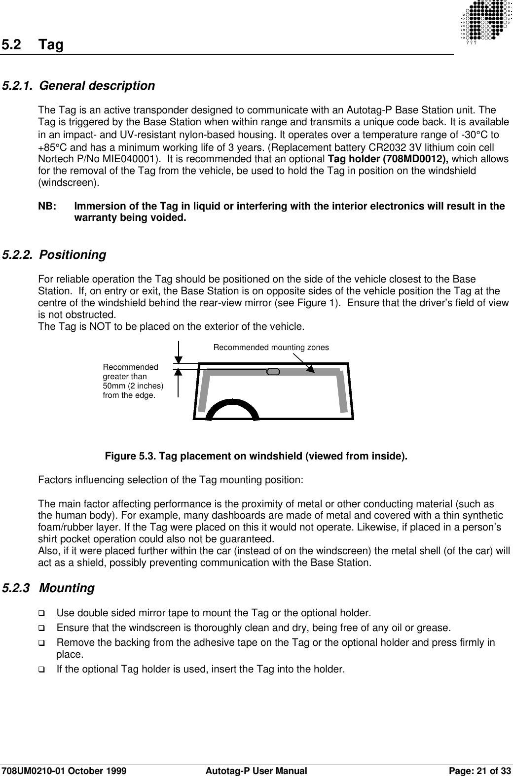
user manual
Contents
1.
user manual
2.
installation guide
user manual
Navigation menu
Upload a User Manual
Namespaces
Wiki Guide
HTML
PDF
Info
Views
User Manual
Discussion / Help
Navigation