Nortech ATR434P Autotag Base Station User Manual users
Nortech International (PTY) LTD Autotag Base Station users
Nortech >
Contents
- 1. user manual
- 2. installation guide
user manual

Nortech International (Pty) Ltd
P O Box 4099 32A Wiganthorpe Road
Willowton Hub Pietermaritzburg
Pietermaritzburg 3201 South Africa
3200 South Africa Reg. No. 98/10951
Tel: (033) 345 3456 Int. Tel: +27 33 345 3456
Fax: (033) 394 6449 Int. Fax: +27 33 394 6449
mkt@nortech.co.za www.nortech .co.za
AUTOTAG-P
USER MANUAL
NORTECH INTERNATIONAL (PTY) LTD
All rights reserved
Copyright 1999
Document No: 708UM0210-01
Date of issue: October 1999
This document is for information only and unless otherwise indicated, is not to form part of any contract. In
accordance with the manufacturer’s policy of continually updating and improving design, specifications
contained herein are subject to alteration without notice.
APPROVALS
Originator L. Grove / M.T. Maggs
Checked: ______________________________ Date: __________________
Engineering Manager: _____________________________
Approved: ______________________________ Date: __________________
Marketing: _____________________________
Checked and approved: ______________________________ Date: __________________
Date: dd/mm/yy Rev CRN No.
22/07/98 00 0451
15/09/99 01 0640

708UM0210-01 October 1999 Autotag-P User Manual Page: 2 of 35
Table of Contents
1. INTRODUCTION...........................................................................................................................4
2. TECHNICAL DATA.......................................................................................................................6
2.1. System Parameters ................................................................................................................6
2.2. Autotag-P Base Station ATR430P series................................................................................6
2.2.1. Electrical...........................................................................................................................6
2.2.2. Mechanical.......................................................................................................................6
2.2.3. Environmental ..................................................................................................................6
2.2.4. RF Channel......................................................................................................................6
2.2.5. Communications...............................................................................................................7
2.2.6 Relay Outputs...................................................................................................................7
2.3. Autotag-P Tag Transponder AT430P......................................................................................8
2.3.1. Electrical...........................................................................................................................8
2.3.2. Mechanical.......................................................................................................................8
2.3.3. Environmental ..................................................................................................................8
2.3.4. RF Channel......................................................................................................................8
2.3.5. Code ................................................................................................................................9
2.4. Autotag-P Tag with Proximity Transponder.............................................................................9
3. FCC REGULATIONS..................................................................................................................10
4. OPERATING PRINCIPLES.........................................................................................................11
4.1. Radio Frequency Communications: Important concepts .......................................................11
4.1.2. Reflection and absorption...............................................................................................12
4.1.3. Noding and nulls.............................................................................................................12
4.1.4. Radiation pattern............................................................................................................13
4.2. Autotag-P Communications Architecture...............................................................................14
4.3. Coding..................................................................................................................................14
4.3.1 32 Bit User Data (Tag only) ............................................................................................14
4.3.2 16 Bit Installer Code.......................................................................................................15
4.3.3 8 Bit Distributor / OEM Code ..........................................................................................15
4.3.4 32 Bit Mask (Base Station Only).....................................................................................15
4.4 R.F. Communications between Base Station and Tag ..........................................................15
4.4.1. Poll from the Base Station..............................................................................................15
4.4.2 Response from the Tag..................................................................................................15
4.4.3 Acknowledge from the Base Station...............................................................................15
4.5. Communication Protocol Options..........................................................................................16
4.5.1 Wiegand Communication Protocol..................................................................................16
4.5.2 Clock&Data Communication Protocol.............................................................................16
4.5.3 RS-232 – Autotag-P Point-to-point Communication Protocol..........................................17
4.5.4 RS-485 – Nortech Multi-drop Communication Protocol...................................................17

708UM0210-01 October 1999 Autotag-P User Manual Page: 3 of 33
5. INSTALLATION..........................................................................................................................18
5.1. Base Station .........................................................................................................................18
5.1.1 General description ........................................................................................................18
5.1.2. Autotag-P Base Station Packing List ..............................................................................18
5.1.3. Installation......................................................................................................................19
5.1.4. Wiring.............................................................................................................................20
5.2 Tag .......................................................................................................................................21
5.2.1. General description ........................................................................................................21
5.2.2. Positioning......................................................................................................................21
5.2.3 Mounting ........................................................................................................................21
5.3. Base Station Configuration Options ......................................................................................22
5.3.1 Base Station DIPSwitch settings:....................................................................................23
5.3.2 Range adjustment: .........................................................................................................25
5.3.3 Internal Diagnostic LED:.................................................................................................25
5.3.4 External Indicator Drivers ...............................................................................................25
5.4. Commissioning .....................................................................................................................25
6. CONFIGURATION......................................................................................................................27
6.1. Wiring Detail .........................................................................................................................27
7. CUSTOMER FAULT ANALYSIS ................................................................................................28
APPENDIX A – WIRING DIAGRAMMS.............................................................................................30
APPENDIX B – GOOSENECK MOUNTING PLATE.........................................................................33
708UM0210-01 October 1999 Autotag-P User Manual Page: 4 of 33
{tc ""}1. INTRODUCTION
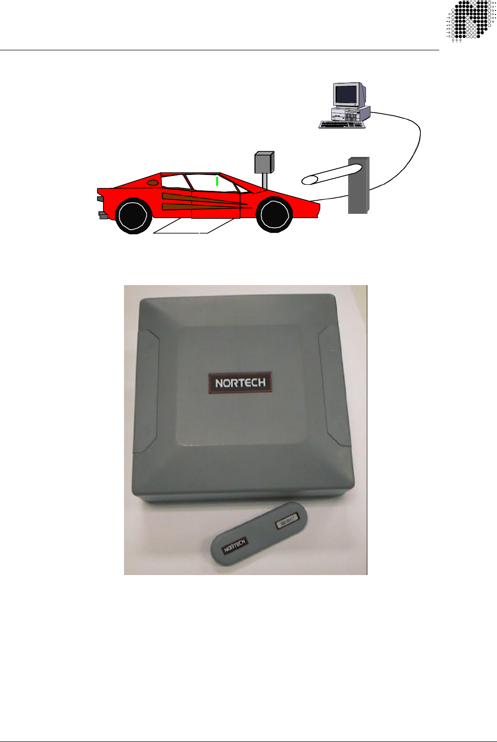
The Autotag-P is a long range, hands free, vehicle identification system used in vehicular access applications.
The configuration consists of:
- a Base Station transceiver,
- portable programmable Tags.
- a loop detector (optional)
Figure 1.1. Configuration
Both the Tags and the Base Station are microprocessor controlled. This allows for increased robustness of the
RF link, and flexibility with respect to coding and system configuration.
The Tag is positioned on the windscreen and is automatically triggered when the vehicle approaches within a
set distance of the Base Station unit. Upon confirming that a Base Station unit is being communicated with, the
Tag transmits a unique code. This code is received by the Base Station and is passed on to the associated
access controllers.
708UM0210-01 October 1999 Autotag-P User Manual Page: 5 of 33
Two possible modes of operation exist:
1. A loop detector informs the Base Station of the presence of a vehicle. The Base Station then transmits a Poll
signal to the Tag, which responds with an ID code. The code is verified by the Base Station, which then initiates
further action (eg. opening of a barrier).
2. The Base Station continually transmits a signal, thus waking up the Tag as soon as it comes within range.
This renders the loop redundant and reduces the cost of the system.
Both configurations have their advantages. The first has increased integrity and reduces the chance of
accidental triggering. It also drastically reduces the average radiation of the Base Station. The second has lower
configuration and installation costs.
Communication between the Base Station and the associated control system (eg. time-and-attendance monitor)
is via a choice of industry-standard protocols.
This document applies to the following models in the Autotag-P range:
AUTOTAG-P BASE STATION MODELS
FT Number Part Number Voltage Protocol
708FT0231 ATR431P-C2 115V AC Clock & Data / Wiegand and RS-232
708FT0232 ATR432P-C2 230V AC Clock & Data / Wiegand and RS-232
708FT0233 ATR434P-C2 12-24V DC Clock & Data / Wiegand and RS-232
708FT0241 ATR431P-C4 115V AC RS-485
708FT0242 ATR432P-C4 230V AC RS-485
708FT0243 ATR434P-C4 12-24V DC RS-485
AUTOTAG-P TRANSPONDER MODELS
FT Number Part Number Model
708FT0210 AT430P Programmable Tag
708FT0212 ATP430P Programmable Tag with Proximity Transponder
RELATED DOCUMENTS:
708LF0211 Autotag-P Base Station Installation Guide
708LF0210 Autotag-P Tag Installation Guide
708DS0210 Autotag-P Data Sheet
708UM0201 Autotag-P Programming Station User Manual

708UM0210-01 October 1999 Autotag-P User Manual Page: 6 of 33
2.TECHNICAL DATA
2.1. System Parameters
Configuration Encoding: One Byte Distributor / OEM code (Allows for 255
unique distributor / OEM’s).
Two Byte Installer code (Allows for 65536 installers
for each Distributor / OEM code).
Refer to Autotag-P Programmable Station User Manual Document Number 708UM0201 for more
information,
2.2. Autotag-P Base Station ATR430P series
2.2.1. Electrical
Power Supply: 120V AC 708FT02X1 ATR 431P
230V AC 708FT02X2 ATR 432P
12 - 24V DC 708FT02X3 ATR 434P
(Where X = 3 – RS-232 model
= 4 – RS-485 model)
Supply Tolerance: +10%
Current Consumption: <200mA at 24V
Protection: Metal Oxide Varistor’s, LC filtering & Transorb spike protector of
the supply lines
2.2.2. Mechanical
Dimensions: 220 mm x 220 mm x 67 mm
Material: ABS Plastic
Mounting: See Mounting Instructions (Section 4.1.2)
2.2.3. Environmental
Storage Temperature: -40°C to +85°C
Operating Temperature: Mains versions -40°C to +70°C
DC versions -40°C to +85°C
Humidity: 98% max.
Environmental Sealing: IP56
Other: UV resistant
2.2.4. RF Channel
Operating Frequency: 433.92 Mhz nominal
Intentional Radiator Compliance: Complies to the following:
ETSI I-ETS 300 220 (European Community)

708UM0210-01 October 1999 Autotag-P User Manual Page: 7 of 33
EMI/EMC Compliance: ETSI I-ETS 300 683
RF Output Power: Adjustable to maximum of +10 dBm (10 mW)
Transmitter Modulation Type: 100% AM (OOK), PWM
Transmit Modulation Frequency: 167 Hz to 250 Hz
Transmitter Data Rate: 10 Bytes / sec
Transmitter Stability: SAW resonator referenced
Receive Modulation Frequency: 375 Hz & 500 Hz
Receive Data Rate: 50 Bytes / sec
Receiver Stability: Crystal referenced
Polarisation: Elliptical
2.2.5. Communications
Interfacing protocols: WIEGAND, CLOCK & DATA and RS-232 or RS-485 only.
Protection: Transorbs on all external communications lines. Opto-isolator on
arming input
Connectors: Mains – 3 way plugable screw terminal
DC power & relay – 5 way plugable screw terminal
Interface and communications two by 6 way pluggable screw
terminals
2.2.6 Relay Outputs 5 Amp @ 230V AC single pole change over

708UM0210-01 October 1999 Autotag-P User Manual Page: 8 of 33
2.3. Autotag-P Tag Transponder AT430P
2.3.1. Electrical
Power Supply: Replaceable 3V CR2032 lithium coin cell
Current consumption: Quiescent: <5 uA
Transmitting:<3 mA
Battery Life: 3 years +
2.3.2. Mechanical
Dimensions: 120 x 32 x 11 mm
Material: ABS Plastic
Mounting: See Mounting Instructions (Section 4.2.2)
2.3.3. Environmental
Storage Temperature: - 40°C to +85°C
Operating Temperature: -30°C to +85°C
Humidity: 98% max.
Environmental Sealing: Sealed to IP42
Other: UV resistant
2.3.4. RF Channel
Operating Frequency: 433.92 MHz.
Operating Range: 8m maximum, adjustable, depending on site conditions
Receiver Modulation Type: 100% AM (OOK), PWM
Receiver Modulation Frequency: 167 Hz to 250 Hz
Receiver Data Rate: 10 Bytes / sec
Transmitter Power: 30 µW
Transmit Modulation Frequency: 375 Hz & 500 Hz
Transmit Data Rate: 50 Bytes / sec
Stability: SAW resonator referenced

708UM0210-01 October 1999 Autotag-P User Manual Page: 9 of 33
2.3.5. Code
System coding: 24 bits fixed
User coding: 32 bit programmable
No. of possible codes: Over 4 billion (232) unique codes
2.4. Autotag-P Tag with Proximity Transponder
Specifications of Proximity Transponder:
EM4002: Compatible
Operating Frequency: 125 kHz
Range: 1 – 3 cm
Coding: 32 bit fixed (not sequential)

708UM0210-01 October 1999 Autotag-P User Manual Page: 10 of 33
3. FCC REGULATIONS
When this system is used in the United States of America, only the following models may be used:
AUTOTAG-P BASE STATION MODELS
FT Number Part Number Voltage Protocol
708FT0233 ATR434P-C2 12-24V DC Clock & Data / Wiegand and RS-232
708FT0234 ATR434P-C2 12-24V DC Clock & Data / Wiegand and RS-232
(McGann)
AUTOTAG-P TRANSPONDER MODELS
FT Number Part Number Model
708FT0210 AT430P Programmable Tag
708FT0211 AT430P Programmable Tag (McGann)
User in the United States of America.
Please note the following important caution:-
BASE STATION ID LABEL
TAG FCC INFORMATION
Changes or modifications to this product not expressly approved by Nortech
International (Pty) Ltd, in writing, could void the user’s authority to operate
the product.
{PRIVATE }Nortech International
(Pty) Ltd ATR434P-C2
(708FT0233)
FCC ID: XXXXX-XXXX
Frequency: 433.92 MHz
Power: 10 mW
{PRIVATE }Nortech International
(Pty) Ltd AT43P (708FT0210)
FCC ID: XXXXX-XXXX
Frequency: 433.92 MHz
Power: 30 µW
708UM0210-01 October 1999 Autotag-P User Manual Page: 11 of 33
4.OPERATING PRINCIPLES
4.1. Radio Frequency Communications: Important concepts
The Autotag-P Base Station and Tags communicate by means of radio waves. Although these are very useful,
as no physical link is needed, they also have some inherent properties which need to be understood for the
installation to work well.
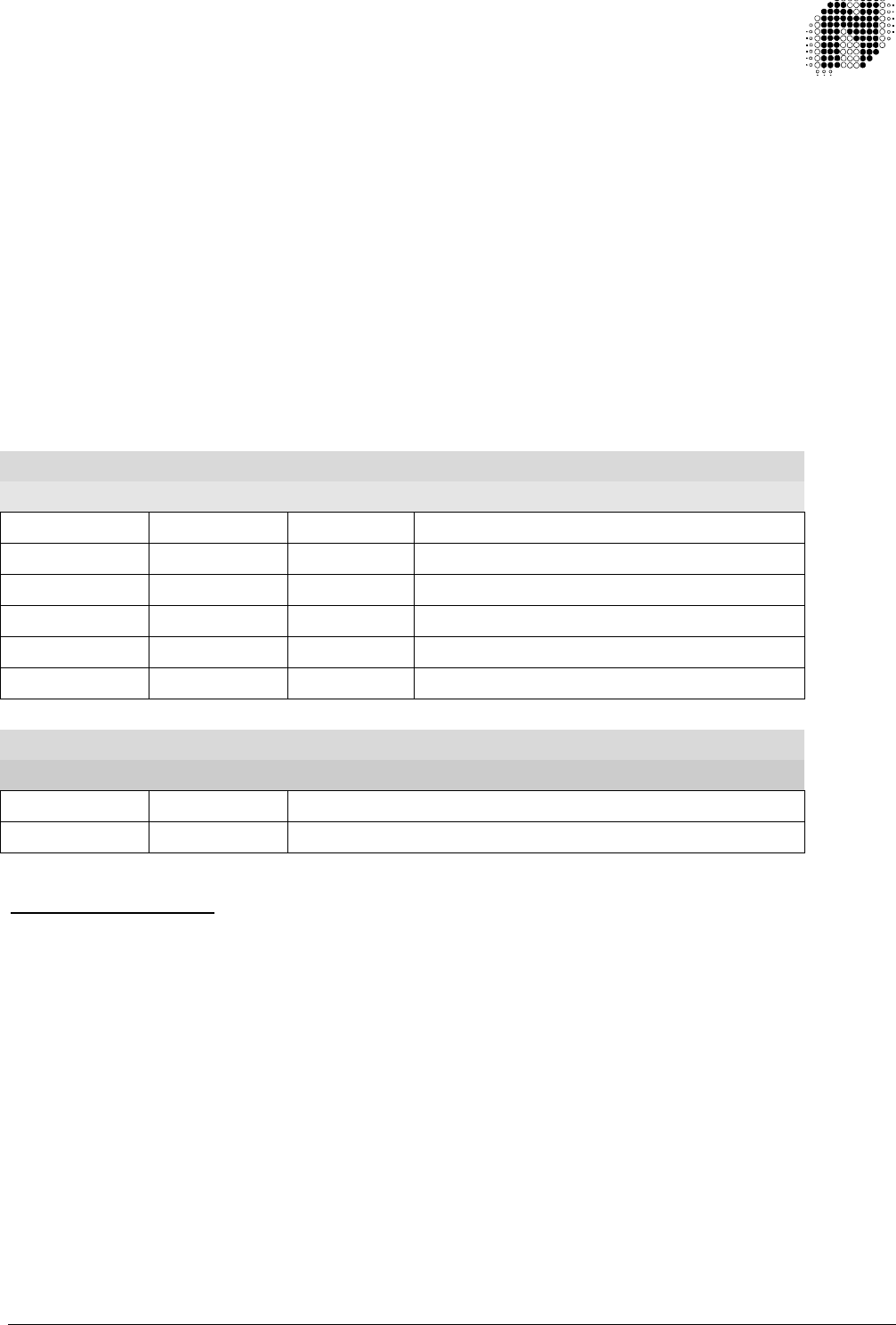
Tag
Base Station
Figure 4.1: Isometric view of Base Station with Tag
4.1.1. Maximum Range
Range is defined as the greatest distance between the Base Station and the Tag, at which reliable
communications can take place.
The Autotag-P unit has a guaranteed range of 8 m, influenced to a degree, by background noise levels.
Environmental conditions have a direct impact on the range:
q During business hours, man made radio frequency interference (RFI) is at it’s strongest, hence reducing the
effective range.
q At the Autotag-P operating frequency, wet weather tends to damp long range radio frequency propagation
but has little effect on short range communications, hence increasing range.
The maximum range, therefore, will be achieved on a wet weekend night. This can typically be up to 15 m.
708UM0210-01 October 1999 Autotag-P User Manual Page: 12 of 33
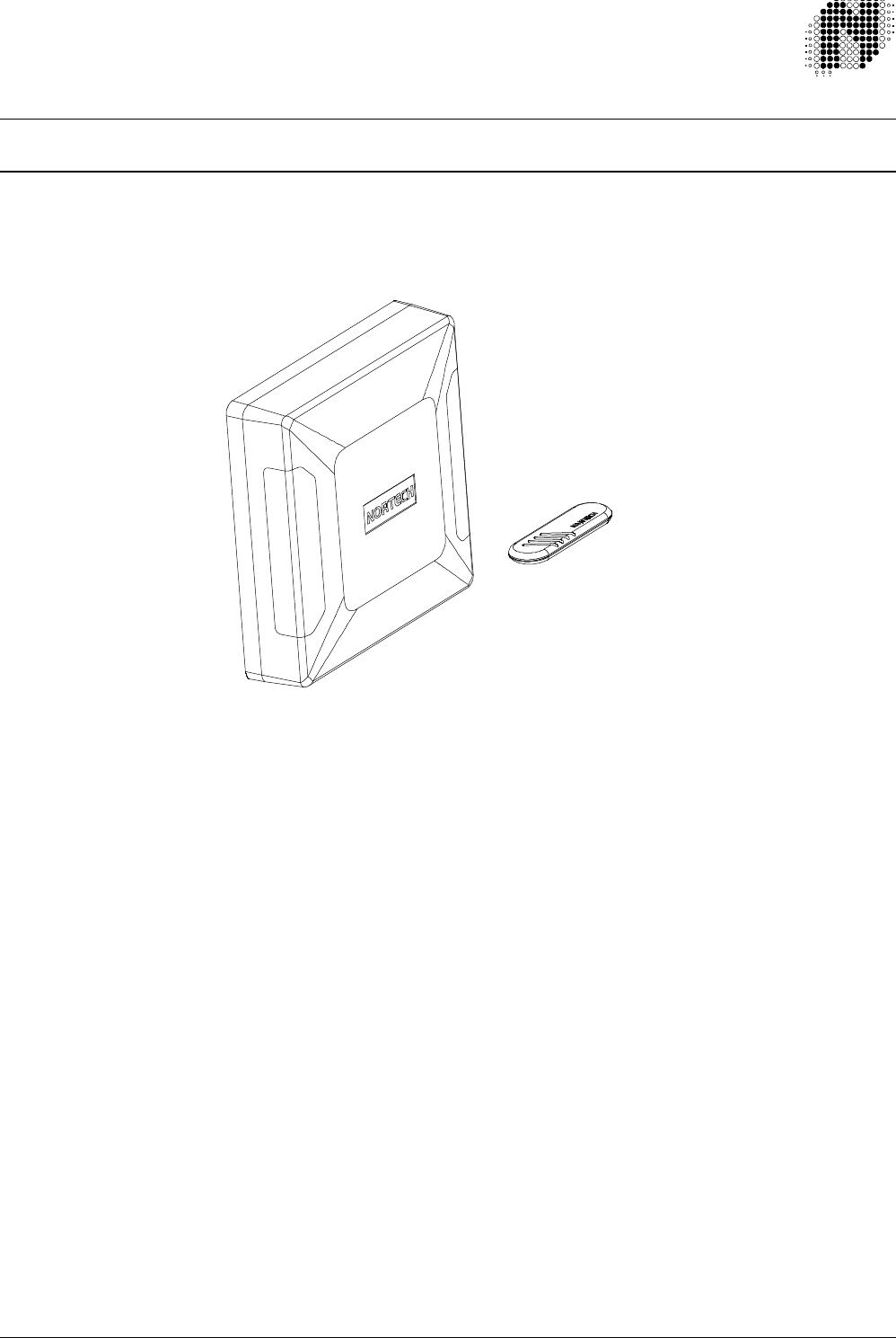
4.1.2. Reflection and absorption
The direction a radio wave travels (and how far it travels) can be affected by its environment. The wave tends to
be reflected by metal surfaces and absorbed by other materials, when passing through them. At most sites
there will be a fair amount of metal in the vicinity, in the form of re-inforcing bars in walls, air conditioning ducts,
etc. For example, if a large metal sheet is placed in front of the Base Station, any Tags on the other side of the
plate would most likely be unable to communicate with the Base Station and the system would not function.
Figure 4.2. Interaction of RF Waves with various materials
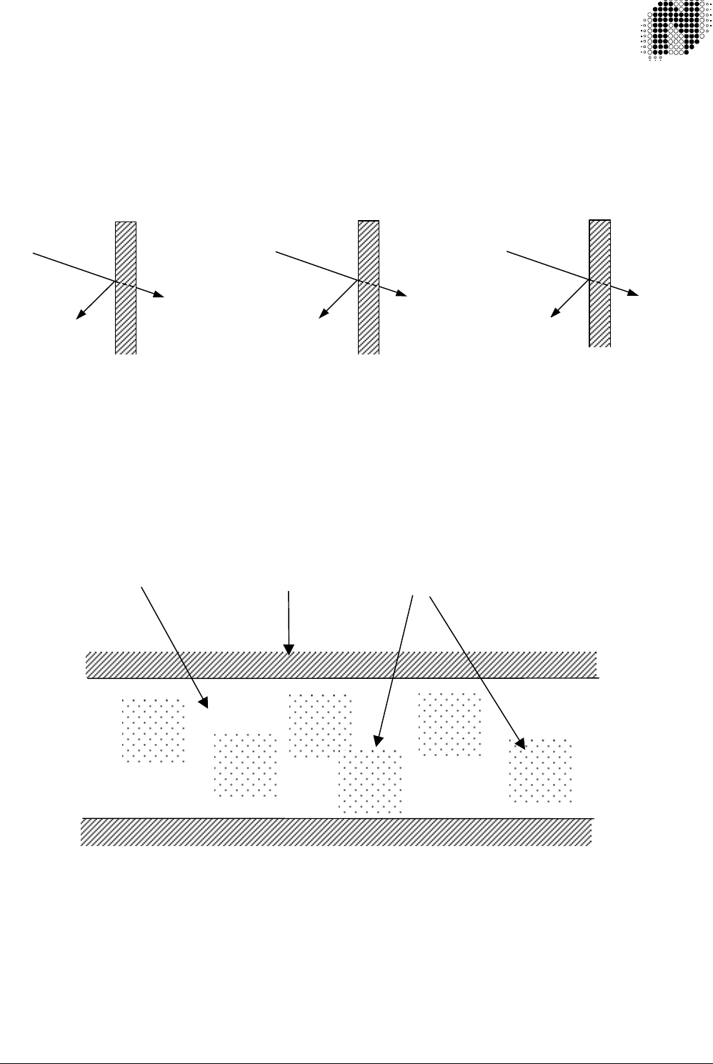
4.1.3. Noding and nulls
A site which is fairly enclosed or has large reflective surfaces in the vicinity, will cause the reflections to interact
with one another. At some points they will interact constructively and there will be a high energy concentration
and at other points the interaction will be negative, resulting in a lower energy concentration.
These ‘lows’ are called nulls, and are points at which the Tags may not receive signals from the Base Station.
Figure 4.3. Distribution of nulls in a confined area
For the Autotag-P unit these nulls will generally be very localised, ie. covering an area of a few tens of
centimetres. A moving vehicle will pass through several peaks and nulls when within range. Transmission will
therefore take place whenever a ‘peak’ has been encountered. During commissioning, as one moves about the
vicinity of the Base Station, this phenomenon can be noticed.
NOTE: The pattern of nulls may be significantly changed by repositioning the Base Station or even simply
angling the unit. For example, where a null covers a relatively large part of the operational zone, repositioning of
the Base Station may be required.
Transmitte
d
Reflected
10% 40-60% >90%
90% 60-
40%
<10%
Nodes
Passage Wall
Wood Reinforced Concrete Metal
Incident
708UM0210-01 October 1999 Autotag-P User Manual Page: 13 of 33
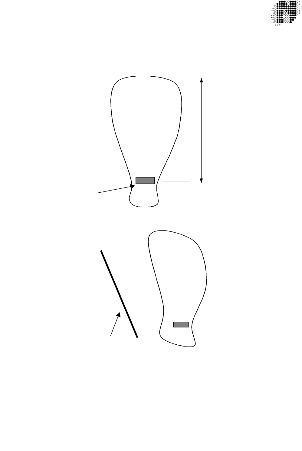
4.1.4. Radiation pattern
The Base Station unit is designed to ensure that the RF waves are transmitted radially outwards, primarily in the
direction of the front face of the unit. (In more scientific terms: there is a main lobe of radiation perpendicular to
the front face.) Tags will therefore operate at maximum range when directly facing the Base Station unit. The
lobe is fairly broad and will therefore work over a wider angle of coverage than simply directly in front of the unit.
Figure 4.4. Radiation pattern of Base Station
Figure 4.5. Influence of nearby metal object on pattern
(This was done to give the unit a degree of directionality, so that one could ‘aim’ it in the required direction.)
Due to the nature of RF, this lobe is not very defined and its shape may change, depending on the local
environment. For example, if the unit is positioned close to a metal gate (see Figure 4.5) the lobe will tend to
bend towards it. If one is situated in an enclosed area, the radio waves tend to reflect off the enclosing walls,
and they set up nodes and nulls in the area. As stated earlier, this will not significantly compromise operation, as
the nulls will tend to cover small areas, each surrounded by an area of good signal strength. The most important
point here is that the lobe shape has now changed considerably and become more unpredictable. For example,
one may now be able to detect a Tag 3 to 5 metres behind the unit.
8 m
Base Station
Metal Gate

708UM0210-01 October 1999 Autotag-P User Manual Page: 14 of 33
Summary of important points about RF:
• RF is unable to penetrate most metals. (For example, talking to someone in a room with metal walls over a
hand held radio is impossible. RF can however go around the walls.)
• RF may be reflected by walls and other structures, especially those with metal reinforcing.
• RF becomes weaker with distance.
4.2. Autotag-P Communications Architecture
Communication between the Tag and Base Station takes place as follows:
As stated in the Introduction (Section 1.) there are two ways of configuration. These depend on site conditions
and requirements in terms of functionality.
1. An arming input is provided. This is a relay input and the triggering device could be a loop detector,
mass detector or some similar device. This allows for triggering of the Base Station only when a vehicle
is present. The Base Station is then only transmitting at such times. The advantages of using this are:
-It reduces the chance of false triggering (eg. by a pedestrian walking past with a Tag).
-The intermittent transmission reduces possible interference with other devices that may be
operating at the same frequency in the vicinity.
-The time-averaged radiation from the device is greatly reduced. This may in some cases be
important for compliance with local EMC regulations.
2. Should the arming input not be used, the Base Station will continually transmit a signal. The advantages
of this are:
-The Tag is triggered as soon as it comes within range, and sensitivity to nulls is reduced.
-The loop or other triggering device is made redundant, reducing the system and installation
costs.
The following applies to both configurations:
The Base Station transmits a signal to any Tags within range. The Tag is activated by this signal. It then checks
to see that it is actually a Base Station that has woken it up. It does this by decoding the code that was
transmitted. Once satisfied, it then transmits its own 32 bit code. The code is received and checked for integrity
by the Base Station and then passed on to the control system via the communications connector.
4.3. Coding
The coding in the Autotag-P system is split into the following sections:
32 bit User Data (Tag only)
16 bit Installer code
8 bit Distributor / OEM code
32 bit mask (Base Station only)
4.3.1 32 Bit User Data (Tag only)
The 32 bit User Data can be programmed into the Base Station and Tag using the Autotag-P
Programming Station. The 32 bits of User Data can be programmed in any combination of site code
bits and card number bits to match the access controller’s requirements.
This feature makes the Autotag-P system very flexible, enabling configuration to most access
controllers.
For more information on Programming the 32 bit user data, refer to the Autotag-P Programming Station
User Manual Document Number 708UM0201.
The Autotag-P Tags are shipped from the factory with the 32 bit User Data set to the Tag’s serial
number.

708UM0210-01 October 1999 Autotag-P User Manual Page: 15 of 33
4.3.2 16 Bit Installer Code
As the 32 bit User Code is programmable, there is a possibility that two Tags from different installation
will have the same code, hence allowing access to the other site.
Therefore the introduction of the Installer code. This 16 bit code allows for 65535 Installer codes for
each Distributor code. The Distributor, programs this code into the Autotag-P Base Station and Tags for
the Installer, using the Autotag-P Programming Station. The 16 bit Installer code in the Base Station
and Tag must match before the Base Station sends the 32 bit User Data to the access controller. The
Autotag-P Base Station and Tags are shipped from the factory with the 16 bit Installer code set to
“00000” (the default Installer code).
4.3.3 8 Bit Distributor / OEM Code
The 8 bit Distributor / OEM code allows for 255 Distributor / OEM codes. This code is programmed in to
the Autotag-P Base Station and Tags by the Distributor / OEM using the Autotag-P Programming
Station. The 8 bit Distributor / OEM code in the Base Station and Tag must match before the Base
Station sends the 32 bit User Data to the access controller. The Autotag-P Base Station and Tags are
shipped from the factory with the 8 bit Distributor / OEM code set to “000” (the default Distributor / OEM
code).
4.3.4 32 Bit Mask (Base Station Only)
This is an advanced feature and it is recommended that this section is left at “0000000000”. If any bit
of this 32 bit Mask is set, the corresponding bit of the Tag’s 32 bit User Data must also be set.
4.4 R.F. Communications between Base Station and Tag
The communications between Base Station and Tag are split into the following sections:
Poll: From Base Station
Response: From the Tag
Acknowledge: From the Base Station
4.4.1. Poll from the Base Station
The Base Station Polls for the Tag at regular intervals, listening for a response from a Tag between
each Poll. The “Poll” contains the following: Poll command, Base Station ID and a Check Digit.
4.4.2 Response from the Tag
On receiving a Poll from the Base Station, the Tag checks the Poll message against the Check Digit. If
it is a valid Poll the Tag returns a response message using the Base Station ID from the Poll message.
The “Response” contains the following: Response Command, Base Station ID, Distributor Code,
Installer Code, 32 Bit User Data and a Check Digit.
4.4.3 Acknowledge from the Base Station
On receiving a response from a Tag, the Base Station checks the response message against the Check
Digit. If it is a valid Response Message, the Base Station checks the “ Base Station ID” in the response
message against it’s own Base Station ID to see if the message has not been sent from a Tag
associated with another Base Station. If the Base Station ID’s match, the Base Station sends out an
Acknowledge Message. The “Acknowledge” contains the following: Base Station ID, the 12 least
significant bits of the Tag’s 32 bit User Data and a Check Digit.
On receiving the Acknowledge Message, the Tag checks the integrity of the message and that it is an
acknowledgement to it’s response message. If all match, the Tag goes to sleep, for typically 7 seconds
(min 3.5 sec, max 11.5 sec). This sleep period reduces the Tags power consumption and allows other
Tags in range to communicate with the Base Station. If the Tag goes out of range of the Base Station, it

708UM0210-01 October 1999 Autotag-P User Manual Page: 16 of 33
will power down. Coming back into range will reinitiate the entire communication
sequence.
4.5. Communication Protocol Options
There are four communications options available:
Wiegand – 34 or 26 Bit
Clock&Data – 10 or 8 Digit BCD
RS-232 – Autotag-P Point-to-point Protocol
RS-485 – Nortech Multi-drop Protocol
There are two basic communication models either the 708FT023X models or the 708FT024X models (where ‘X’
is the power supply option)
The 708FT023X models have the “RS-232 Autotag-P Point-to-point Communication Protocol”. Where as
the 708FT024X models have “RS-485 – Nortech Multi-drop Communication Protocol”
The 708FT023X models come standard with both Wiegand and Clock&Data communications protocols.
The selection between either Wiegand or Clock&Data is via DIP Switch SW1-3
Other communication protocols are available on special request.
4.5.1 Wiegand Communication Protocol
Refer to section 5.3.1 for switch locations and settings.
This is a unidirectional protocol (from the Autotag-P Base Station to the Access Controller).
One of two versions of this protocol can be selected. Either 34 bit or 26 bit Wiegand. The default is 34 bit
Wiegand. To select 26 bit Wiegand switch OFF switch SW2-2. To revert back to 34 bit Wiegand switch ON
switch SW2-2.
For 34 bit Wiegand Protocol (SW2-2 and SW2-3 ON), (being the preferred version of this protocol). The 32 bit
unique code from the Autotag-P Tag is sent out with the addition of two parity bits
For the 26 bit Wiegand protocol (SW2-2 OFF and SW2-3 ON). The 32 bit unique code from the Autotag-P Tag
has the eight most significant bits striped off and the resultant 24 bits are sent out with the addition of two parity
bits
4.5.2 Clock&Data Communication Protocol
Refer to section 5.3.1 for switch locations and settings.
This protocol is also known as “Magnetic Stripe Track 2.”
This is a unidirectional protocol (from the Autotag-P Base Station to the Access Controller).
One of two versions of this protocol can be selected. Either 10 digit or 8 digit Clock&Data. The default is 10 digit
Clock&Data. To select 8 digit Clock&Data, switch OFF switch SW2-2. To revert back to 10 digit Clock&Data
switch ON switch SW2-2.
For 10 Digit Clock & Data Protocol (SW2-2 ON and SW2-3 OFF), (being the preferred version of this protocol).
The 32 bit unique code from the Tag is converted to 10 digit BCD. Each BCD digit gets its own parity bit. The
resultant digits together with a message header and footer are used to calculate the message check digit.
For 8 Digit Clock & Data protocol (SW2-2 OFF and SW2-3 OFF). The 32 bit unique code from the Tag is
converted to 10 digit BCD. The two most significant BCD digits are discarded. Each of the remaining eight BCD

708UM0210-01 October 1999 Autotag-P User Manual Page: 17 of 33
digits gets its own parity bit. The resultant digits together with a message header and footer are
used to calculate the message check digit.
4.5.3 RS-232 – Autotag-P Point-to-point Communication Protocol
Refer to section 5.3.1 for switch locations and settings.
This is a unidirectional protocol where the unique code read from the Autotag-P Tag is sent out on the RS-232
transmit line.
Data Format: 8 data bits
No parity
One stop bit
Switch selectable: 1200 and 9600 baud
The 32 bit unique code from the Autotag-P Tag is converted to 10 digit BCD. These ten BCD digits are then
converted to ten ASCII digits. The ten ASCII digits are sent out with a Carriage Return Line Feed (CRLF)
terminator.
The total length of the communications wires is limited to 10 meters (30 feet)
4.5.4 RS-485 – Nortech Multi-drop Communication Protocol
This is a bi-directional multi-drop protocol where up to 32 Autotag-P Base Stations and one Access Controller
can be connected to the same two communication wires.
The Access Controller polls each Base Station in turn to check if the Base Station has any information. When
it’s the Autotag-P Base Station’s turn the unique code read from Autotag-P Tag is sent to the Access Controller.
Data Format: 8 data bits
No parity
One stop bit
Switch selectable: 1200 and 9600 baud
The 32 bit unique code from the Autotag-P Tag is converted to 10 digit BCD. These ten BCD digits are then
converted to ten ASCII digits. The ten ASCII digits together with a Carriage Return Line Feed (CRLF) terminator
are only sent out when requested to do so by the Access controller.
The total length of the communications wires is limited to 1200 meters (4000 feet).
708UM0210-01 October 1999 Autotag-P User Manual Page: 18 of 33
5.INSTALLATION
5.1. Base Station
5.1.1 General description
The Base Station is a robust, weatherproof device capable of being mounted outdoors and of handling wide
temperature / humidity ranges (-40°C to +70°C, 0 - 98% rel. humidity). The casing is constructed of an ABS
plastic, which is impact- and UV-resistant. An O-ring seal is incorporated to ensure minimal ingress of water and
dust. Cable access is via two knockouts, one in the centre of the base for mounting on a goose neck, and one
slightly off-set and lower down, for wall mounting. Access to the electronics is via screws hidden behind clip-in
panels on the front cover.
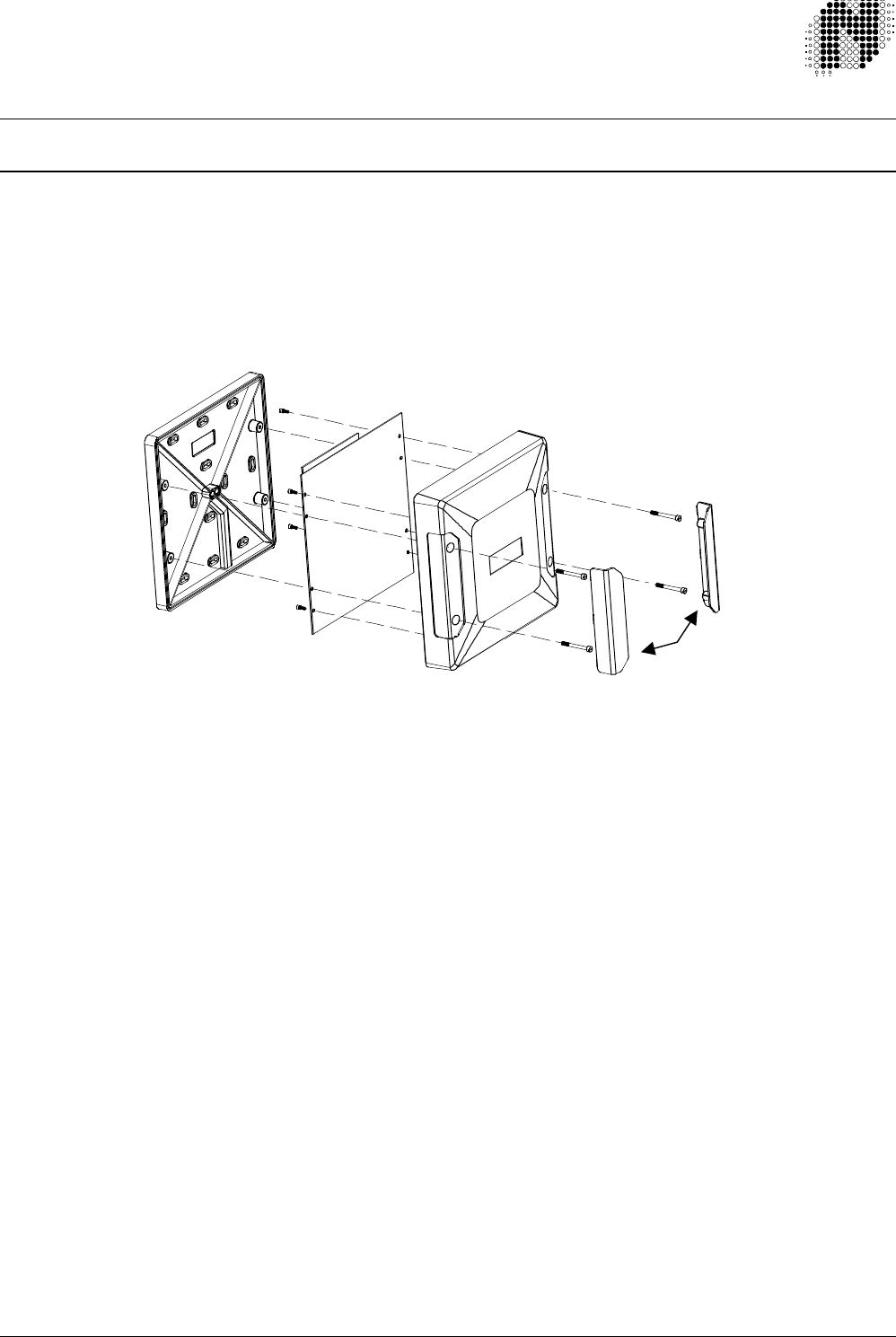
Figure 5.1. Base Station: Exploded View
The Base Station has been designed so that all electronics are recessed into the cover.
This feature allows for issuing the housing Base for mounting, eliminating the risk of damage during installation.
Use of pluggable screw terminals allows for the cabling to be completed before plugging in the electronics,
further reducing the risk of damage to the electronics.
5.1.2. Autotag-P Base Station Packing List
1 x Housing Base
1 x Cover (with electronics fitted)
1 x Installation Instruction Leaflet
1 x Accessory Pack, containing:
2 x Screw Cover Clips
4 x Allen Cap Screws (M4 x 35)
1 x Allen Key
2 x 6 Way Pluggable Screw Terminals
1 x 5 Way Pluggable Screw Terminals
1 x 3 Way Pluggable Screw Terminals (mains version only)
Base
Cover
Screw Cover Clips
708UM0210-01 October 1999 Autotag-P User Manual Page: 19 of 33
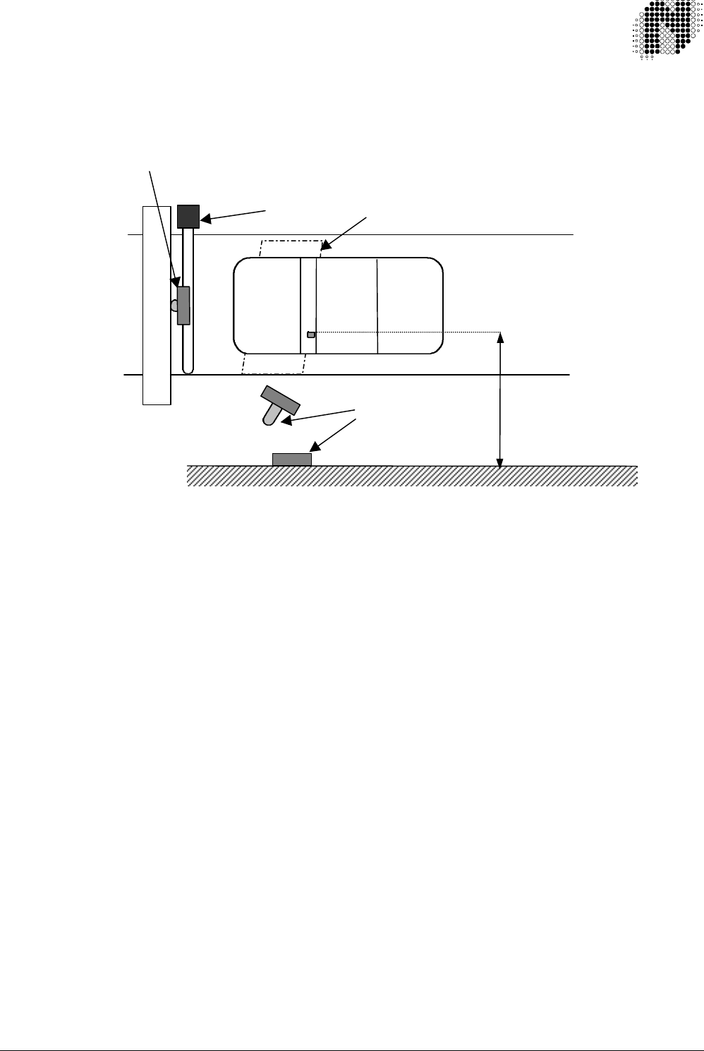
5.1.3.Installation
The unit may be wall, pole or gantry mounted. The height of the mount should be equivalent to the average
vehicle window height. The unit must be positioned so that it ‘looks into’ the vehicle.
Figure 5.2. Positioning
Wall mounting:
Wall mounting is possible when the wall is within the specified range of the vehicles to be monitored.
The presence of metal re-enforcing in the wall has negligible effect on the operation of the Base
Station.
1. Determine the area in which the unit must detect. The Base Station unit should be placed roughly
in the middle of this area (Figure 5.2)
2. Unclip the two screw covers and remove front cover via screws.
3. Knockouts are provided on the base (Figure 4.1). Remove the appropriate knockouts, including
that of the cable access hole.
4. Route power and communications cables through the cable access hole.
5. Bolt base to wall via knockouts.
6. Connect cables according to wiring diagram in Section 5.1.
7. Before applying power: Set the DIP switches according to the type of installation required. If the
‘triggered’ setting is to be used, ensure the arming input is connected and that the trigger system
(eg. loop detector) is functioning.
8. Apply power. The RED LED should be illuminated.
9. Holding a Tag in front of the unit should cause the GREEN LED to light up for a second at a time.
This indicates that the Base Station is receiving the code from the Tag.
NB: The Circuit Board does NOT need to be unscrewed from the front cover at any point.
Doing so will result in the warranty being voided.
8m max.
Gantry mount
Pole and wall
mount
Loop
Boom

708UM0210-01 October 1999 Autotag-P User Manual Page: 20 of 33
Pole or gantry mounting:
1. When mounting on a pole, refer to the dimensions and recommended minimum size on the goose
neck mounting plate drawing in Appendix B.
2. A hole in the centre of the flange with a diameter of 30 mm will allow for hidden cable access.
3. Ensure that the unit faces the window area of the vehicles to be monitored.
4. Mounting instructions are the same as for the above.
5.1.4.Wiring
Refer to Section 6.1 for connector Pin assignment and to Appendix A for additional information.
Refer to section 5.3.1 for switch locations and settings.
5.1.4.1 Connecting the Base Station to a controller:
Wiegand: Connect the following lines: CN7 Pin 4 (DATA0), CN7 Pin 3 (DATA1) and CN5
Pin 1 (GND) to the corresponding terminals on the controller. Ensure that
switch SW2-3 is ON.
Clock & Data: Connect the following lines: CN7 Pin 4 (Clock), CN7 Pin 3 (Data), CN7 Pin 2
(Card Present) and CN5 Pin 1 (GND) to the corres-ponding terminals of the
controller. Ensure that SW2-3 is OFF.
RS-232:This feature is only available on the RS-232 model. Connect CN7 Pin 5 (RS-
232 TX) to the receive pin of the controller. Connect CN7 Pin 6 (RS-232 RX) to
the transmit pin of the controller. Connect CN5 Pin 1 (GND) to the signal GND
Pin of the controller.
RS-485:This feature is only available on the RS-485 model. Connect the following
lines: CN7 Pin 6 (RS-485 A), CN7 Pin 5 (RS-485 B) and CN5 Pin 1 (GND) to
the corresponding terminals of the controller. Ensure that each Base Station
has a unique address by setting switches SW1-1 through SW1-5.
5.1.4.2 Connecting the Base Station to a triggering device:
This is done when the Base Station is to operate in ‘Triggered’ mode. A vehicle detector positioned
directly in front of the Base Station unit is used to trigger operation.
The vehicle detector can be a loop detector, capacitive detector or any other unit capable of providing
a CONTINUOUS relay closure whilst a vehicle is present. In the case of a loop detector this requires
that the unit is configured for PERMANENT PRESENCE.
Connect CN7 Pin1 to the N/O relay output of the triggering device, and CN5 Pin 1 of the screw
terminal block to the RELAY COMMON connection of the triggering device.
5.1.4.3 Operating multiple Base Stations in proximity to one
another:
When two or more Base Station units are operated in proximity to one another they may cause mutual
interference if not synchronised. Synchronisation ensures that their transmissions do not interfere with
one another. To synchronise the units, connect the SYNC lines CN5 Pin 6 and GND CN5 Pin 1 on the
6-pin power connectors to the corresponding pins on all units (ie. Pin 6 to Pin 6, Pin 1 to Pin 1).
(Refer to section 6.1)
In addition to the SYNC function, the Base Station also has Base Station ID switch settings. When
several units are operating on the same site, setting different ID’s for each unit ensures that they only
receive codes from the Tags that they themselves have actuated. That is, Base Station ‘A’ will not
receive the code from a Tag actuated by Base Station ‘B’. See Section 4.3.1 for more information.
708UM0210-01 October 1999 Autotag-P User Manual Page: 21 of 33
5.2 Tag
5.2.1. General description
The Tag is an active transponder designed to communicate with an Autotag-P Base Station unit. The
Tag is triggered by the Base Station when within range and transmits a unique code back. It is available
in an impact- and UV-resistant nylon-based housing. It operates over a temperature range of -30°C to
+85°C and has a minimum working life of 3 years. (Replacement battery CR2032 3V lithium coin cell
Nortech P/No MIE040001). It is recommended that an optional Tag holder (708MD0012), which allows
for the removal of the Tag from the vehicle, be used to hold the Tag in position on the windshield
(windscreen).
NB: Immersion of the Tag in liquid or interfering with the interior electronics will result in the
warranty being voided.
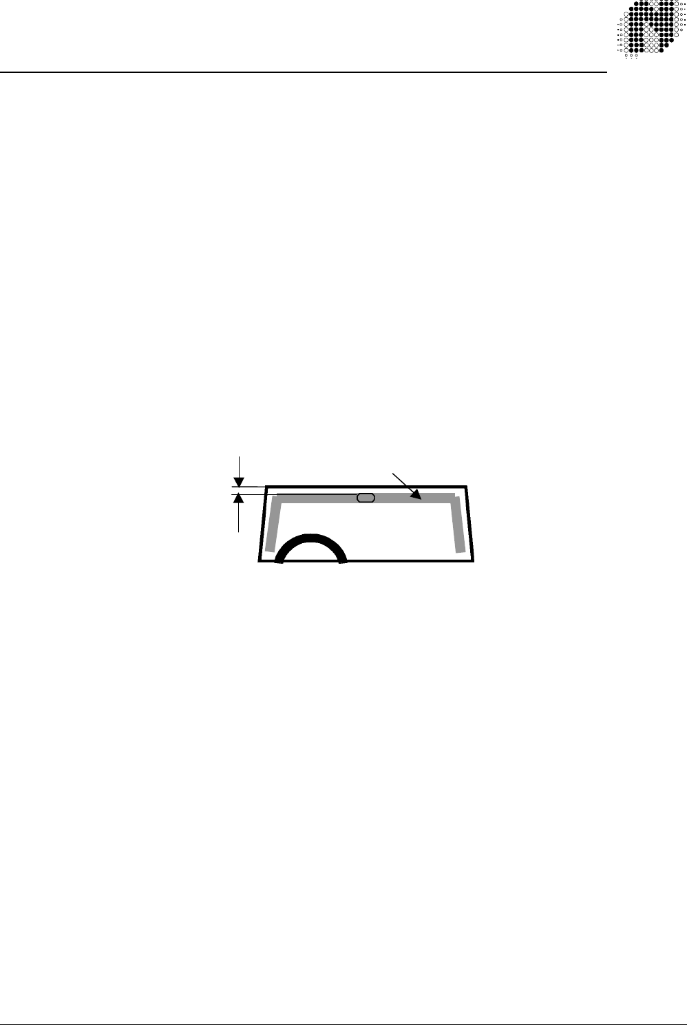
5.2.2. Positioning
For reliable operation the Tag should be positioned on the side of the vehicle closest to the Base
Station. If, on entry or exit, the Base Station is on opposite sides of the vehicle position the Tag at the
centre of the windshield behind the rear-view mirror (see Figure 1). Ensure that the driver’s field of view
is not obstructed.
The Tag is NOT to be placed on the exterior of the vehicle.
Figure 5.3. Tag placement on windshield (viewed from inside).
Factors influencing selection of the Tag mounting position:
The main factor affecting performance is the proximity of metal or other conducting material (such as
the human body). For example, many dashboards are made of metal and covered with a thin synthetic
foam/rubber layer. If the Tag were placed on this it would not operate. Likewise, if placed in a person’s
shirt pocket operation could also not be guaranteed.
Also, if it were placed further within the car (instead of on the windscreen) the metal shell (of the car) will
act as a shield, possibly preventing communication with the Base Station.
5.2.3 Mounting
q Use double sided mirror tape to mount the Tag or the optional holder.
q Ensure that the windscreen is thoroughly clean and dry, being free of any oil or grease.
q Remove the backing from the adhesive tape on the Tag or the optional holder and press firmly in
place.
q If the optional Tag holder is used, insert the Tag into the holder.
Recommended
greater than
50mm (2 inches)
from the edge.
Recommended mounting zones
708UM0210-01 October 1999 Autotag-P User Manual Page: 22 of 33
5.3. Base Station Configuration Options
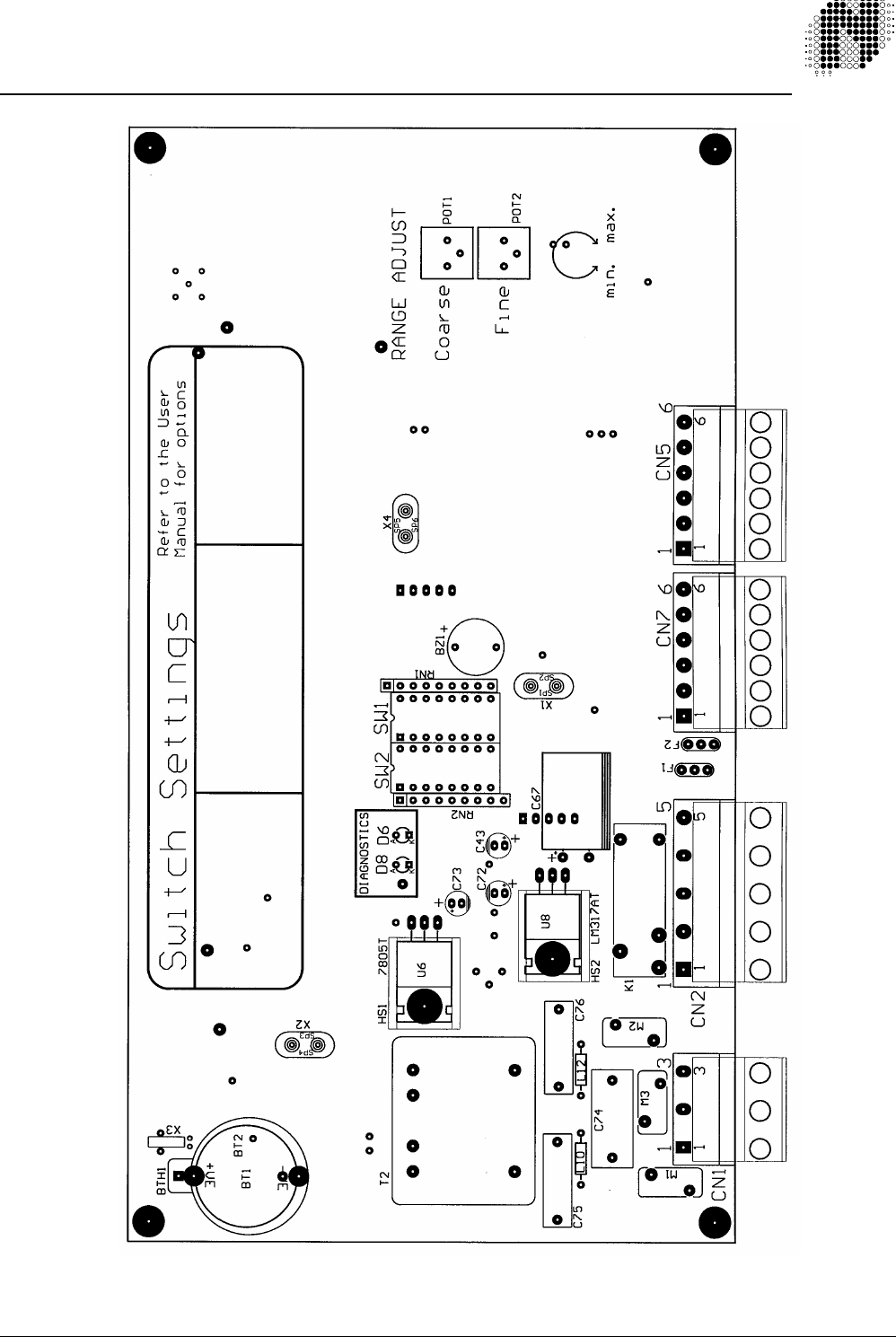
Figure 5.4. Layout of Main board
708UM0210-01 October 1999 Autotag-P User Manual Page: 23 of 33
Refer to the Main Board Layout (Figure 5.4) for the following:
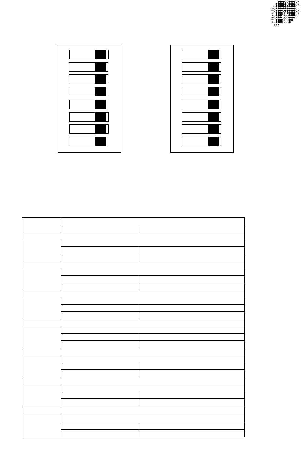
5.3.1 Base Station DIPSwitch settings:
SW2 SW1
Figure 5.5: Picture of DIP Switches as seen on Base Station
With reference to Figure 5.5 the following options are presently available:
Switch 2:
Buzzer
SW2-1 ON Enable
Comms Length
ON 34 Bit/10 DigitSW2-2 OFF 26 Bit / 8 Digit
Protocol
ON WiegandSW2-3 OFF Clock & Data
RS-232 / RS-485
ON RS-232SW2-4 OFF RS-485
Baud Rate
ON 9600SW2-5 OFF 1200
Multiple Read
ON EnableSW2-6 OFF Disable
Mode of Operation
ON TriggeredSW2-7 OFF Continuous
LED Control
ON Controlled by access controller
SW2-8
OFF Controlled by Base Station
1
2
3
4
5
6
7
8
1
2
3
4
5
6
7
8
ON
ON

708UM0210-01 October 1999 Autotag-P User Manual Page: 24 of 33
Switch 1:
If an address switch is ON this represents a binary ZERO if the switch is OFF this
represents a binary ONE.
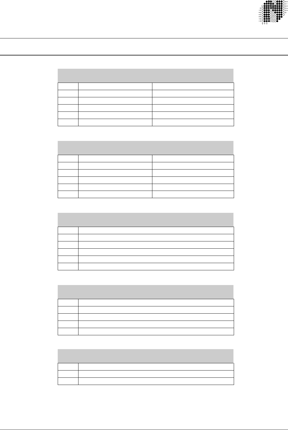
Address/ID SW1-5 SW1-4 SW1-3 SW1-2 SW1-1
0ON ON ON ON ON
1ON ON ON ON OFF
2ON ON ON OFF ON
3ON ON ON OFF OFF
4ON ON OFF ON ON
5ON ON OFF ON OFF
6ON ON OFF OFF ON
7ON ON OFF OFF OFF
8ON OFF ON ON ON
9ON OFF ON ON OFF
10 ON OFF ON OFF ON
11 ON OFF ON OFF OFF
12 ON OFF OFF ON ON
13 ON OFF OFF ON OFF
14 ON OFF OFF OFF ON
15 ON OFF OFF OFF OFF
16 OFF ON ON ON ON
17 OFF ON ON ON OFF
18 OFF ON ON OFF ON
19 OFF ON ON OFF OFF
20 OFF ON OFF ON ON
21 OFF ON OFF ON OFF
22 OFF ON OFF OFF ON
23 OFF ON OFF OFF OFF
24 OFF OFF ON ON ON
25 OFF OFF ON ON OFF
26 OFF OFF ON OFF ON
27 OFF OFF ON OFF OFF
28 OFF OFF OFF ON ON
29 OFF OFF OFF ON OFF
30 OFF OFF OFF OFF ON
31 OFF OFF OFF OFF OFF
Baud Rate:
This switch (SW2-5) is used to select the baud rate for RS-232 and RS-485 communications (on units
supporting these options).
Data Output Protocol:
This switch (SW2-3) is used to select, either Wiegand or Clock & Data Protocol (standard on all units).
RS-485 Multidrop addressing / Base Station ID code:
DIP switches SW1-1 through SW1-5 serve two functions. For units supporting 485 communications,
they allow for individual addressing of each unit. In addition, they allow each unit to ‘fingerprint’ the Tag
it communicates with. This ensures that Base Station ‘A’ doesn’t receive the code from a Tag triggered
by Base Station ‘B’ (as long as the two have different ID code settings).
Allowance has been made for up to 32 different RS-485 addresses and 16 Base Station ID’s.
Transmission mode:
If the Base Station is to operate without any trigger input (such as an arming loop), set the switch to
‘Continuous’. The unit will then continuously transmit its wake-up signal.

708UM0210-01 October 1999 Autotag-P User Manual Page: 25 of 33
If it is to operate with a triggering device, set it to ‘triggered’ and ensure the device is
connected (see section 4.1.3).
5.3.2 Range adjustment:
The range can be adjusted to compensate for local / site conditions and applications.
This is done via the single turn adjustment trimmers on the main board (see figure 5.4).
Note that both the COARSE and FINE trimmers are set to maximum range at the factory.
I.e: turned clockwise to the limit.
NB: Do not try to force them beyond their normal range.
5.3.3 Internal Diagnostic LED:
q Power Up: Red LED goes on to show that power is on, then the Green LED
flashes twice and buzzer beeps twice.
q Normal operation: After power up red LED is on. If the B/S receives a valid ID the green
LED flashes once, the buzzer beeps and on the RS-232 model the
relay will pulse. On the RS-485 model the relay is controlled by the
RS-485 communications.
q Fault condition: If a fault condition occurs, the red LED will flash.
q Wrong Distributor Code: The Red LED flashes OFF twice.
q Wrong Installer Code: The Red LED flashes OFF twice.
q Memory Check Sum Error: The Red LED flashes OFF three times.
5.3.4 External Indicator Drivers
Two external indicators can be connected to the Base Station. Refer to Appendix A: Wiring Diagrams, on how
to connect these indicators.
Each driver has the following maximum ratings: 30V DC 100mA. If the indicators exceed these ratings, external
relays must be used.
Dip Switch SW2-8 selects which device controls the external indicators. If SW2-8 is OFF the Base Station
controls the indicators. If SW2-8 is ON the access controller controls the indicators via the two terminals CN5
Pins 4 & 5
5.4. Commissioning
Once the unit has been installed and is working, the following steps need to be taken.
In the case of a single unit on the site:
1. Apply power to the Base Station.
2. Set the configuration to “Continuous Transmission” (see Section 5.3.1). Adjust the two range
trimmers to maximum range (see Figure 5.4).
3. Attach a Tag to a vehicle that will require access to the site. Follow the steps in Section 5.2, ensuring
that the Tag is mounted in the vehicle, on the side of the windscreen that is closest to the Base
Station unit.
4. Drive up to the unit. Stop the vehicle at the point where it is required that the Tag be detected.
5. Adjust the range adjustment trimmers on the internal PCB of the Base Station until the correct range
is obtained. If the Base Station is detecting the Tag reliably the GREEN LED should light up once
every 5 – 10 seconds. If it isn’t then increase the range.

708UM0210-01 October 1999 Autotag-P User Manual Page: 26 of 33
This delay is caused by the Tag going to sleep making range setting and verification a
tedious operation. To speed up this task a Test Tag (708FT0214) is available. This Test Tag does
not go to sleep, but responds to all valid Polls it receives.
6. Once the range has been set it is a good idea to increase it a little beyond this point to ensure that it
will operate reliably under all conditions.
7. Should the unit be connected to a controller, ensure that the controller receives the code, and that
the two units are configured to use the same communications protocol (ie. Wiegand, Clock & Data,
etc.).
8. Finally, if required, set the transmission mode of the Base Station to “Triggered” (see Section 4.3.1).
NB: If testing the site by holding a Tag in your hand, ensure that you hold it in
the middle of the Tag, between thumb and forefinger. Do not cover its
ends and hold it away from your body.
In the case of multiple units being installed on a site:
1. Work as per the above instructions, testing each unit individually with the other units disconnected.
2. Ensure that the SYNC line of each unit is connected to a common line (see Section 5.1.3). Note:
This is generally only important for units which are within 30m of one another.
3. Ensure that the ID settings for each unit are unique (see Section 5.3.1).
4. Where two units are within 10 m of one another, try to mount them facing away from one another.
This will minimise the chance of a unit reading the wrong Tag. Optimise the range setting of each to
give a reliable read without interfering with the other unit.
5. Power all units up, having set the individual operation modes of each (ie: ‘triggered’ or ‘continuous’).
6. In the case of Base Station units situated very close to one another, drive a tagged vehicle up to
each unit and check whether or not it triggers the wrong Base Station. If it does, this may require
pointing the units away from one another and / or reducing the range of the unit that reads
incorrectly.
708UM0210-01 October 1999 Autotag-P User Manual Page: 27 of 33
6.CONFIGURATION
6.1. Wiring Detail
CN7 6 Way Pluggable Screw Terminal
PIN Wiegand Function Clock & Data Function
1Triggered Input Triggered Input (Arming)
2Not Used Card Present
3DATA 1 Data
4DATA 0 Clock
5As per table below As per table below
6As per table below As per table below
CN7 6 Way Pluggable Screw Terminal
PIN RS-232 Function RS-485 Function
1As per table above As per table above
2As per table above Not Used
3As per table above RS-485 TX Active
4As per table above Not Used
5RS-232 TX RS-485 B
6RS-232 TX RS-485 A
CN5 6 Way Pluggable Screw Terminal
PIN FUNCTION
1Signal Ground
2External Indicator Output – Green
3External Indicator Output – Red
4External Indicator Input – Green
5External Indicator Input – Red
6SYNC
CN2 5 Way Pluggable Screw Terminal
PIN FUNCTION
1Relay Normally Open
2Relay Normally Closed
3Relay Common
4DC Power In Negative
5DC Power In Positive
CN1 3 Way Pluggable Screw Terminal
PIN FUNCTION
1Mains Power Live
2Mains Power Safety Earth
3Mains Power Neutral

708UM0210-01 October 1999 Autotag-P User Manual Page: 28 of 33
7.CUSTOMER FAULT ANALYSIS
Possible problems experienced during commissioning, and their solutions:
FAULT CAUSED BY REMEDY
The site regularly has several
vehicles queuing to enter and exit
the building. The Base Station unit
detects vehicles other than the first
in line, or detects several vehicles
at the same time.
Base Station range set too high or
there is an orientation problem with
the Base Station.
Reduce the range so that only the
nearest vehicle is detected.
If the problem persists then it is
most likely an orientation problem.
In situations where it is important
that individual vehicles are
detected in the correct order (such
as pay-parking), do not mount the
Base Station pointing back along
the line of vehicles (such as on an
overhead gantry). Rather mount it
so that it faces the foremost car
but is pointed away from the
others. For example, mount it to
the side of the lane, pointing
perpendicular to the road (see the
wall mount in Figure 5.2). Also,
mount it as close as possible to the
vehicle, and mount all Tags on the
side of the windscreen closest to
the Base Station. The closer the
Tags are to the Base Station, the
lower the range setting can be,
and the lower the chance of
accidentally waking the wrong Tag.
NOTE: Please read Section 4,
especially 4.1.3 and 4.1.4 for more
information on possible problems
and their solutions.
The Base Station doesn’t read the
Tag, or does so erratically.
The Base Station range is set too
low or multiple Base Stations are
not synchronised.
a) The Base Station may need to
have the range increased
slightly. Do so using the
adjustment trimmers. It may
also be that it needs to be re-
oriented to face the Tags
directly. Ensure that the unit is
facing towards the correct area
of detection. This is especially
important if a triggering device
is to be used. For example, in
the case of a loop detector the
unit must face an area directly
above the loop.

708UM0210-01 October 1999 Autotag-P User Manual Page: 29 of 33
b) For installations involving
multiple Base Stations per site,
ensure that the SYNC and
GND lines (Pins 6 & 1 on CN5
screw terminal) are commoned,
and that each Base Station has
a different ID setting (see
Section 5.3.1).
FAULT CAUSED BY REMEDY
Several Base Stations read a
single Tag’s code simultaneously.
Multiple Base Stations with the
same ID.
Ensure the ID settings are unique
for each Base Station.
The Base Station reads people
walking past holding their Tags.
Base Station is not being activated
by a triggering device.
Ensure the Base Station is
connected to a triggering device
(such as a loop detector) and that
SW2-7 is set to ‘ON’ (triggered
operation). Also, try to situate the
Base Station as far as possible
from any pedestrian access area.
Red Diagnostics and Red external
indicator flashes.
Either the Base Station or the Tag
having an incorrect:
1. Distributor code.
2. Installer code.
Ensure that the Distributor and
Installer codes in both the Base
Station and the Tag match.
708UM0210-01 October 1999 Autotag-P User Manual Page: 30 of 33
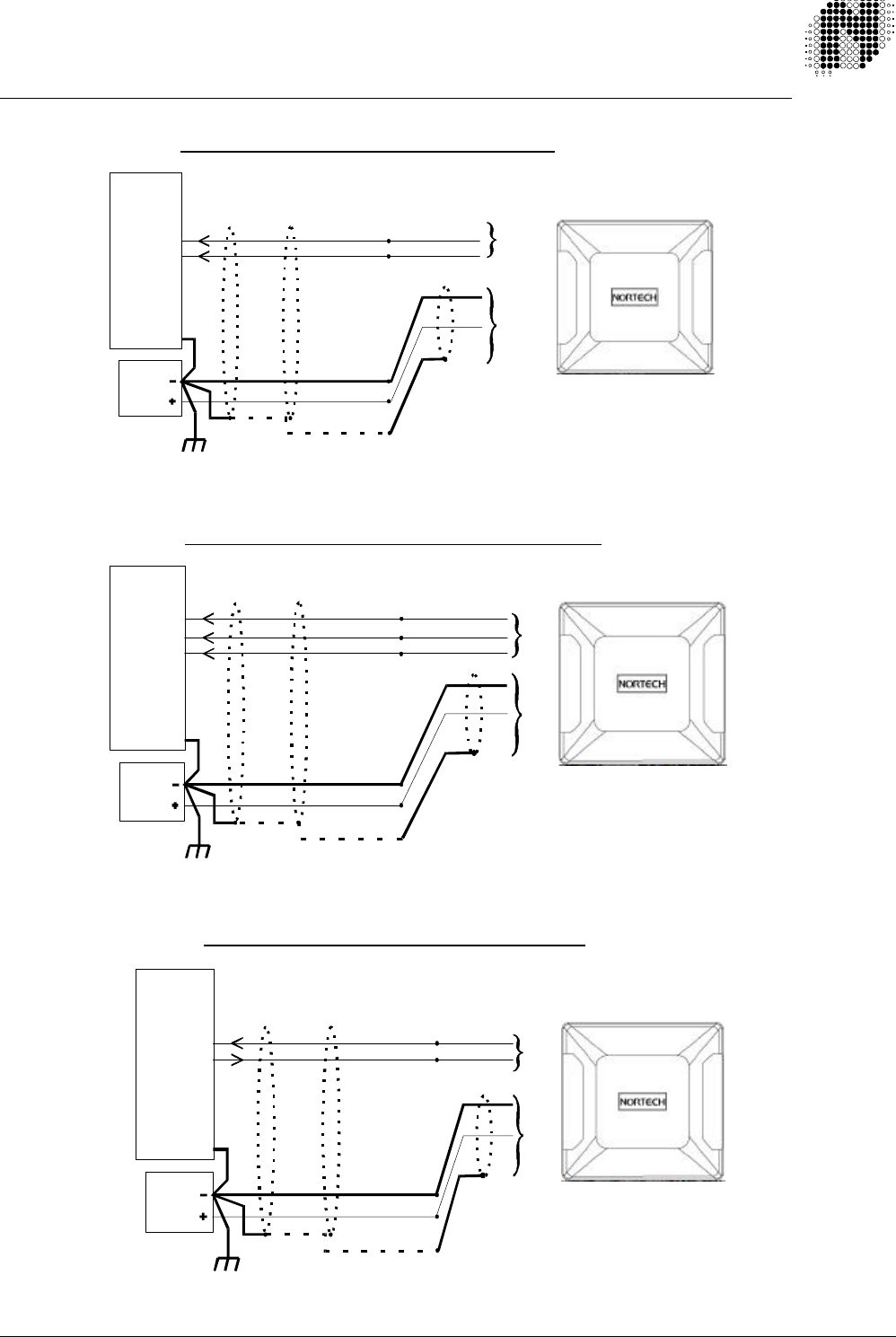
APPENDIX A – WIRING DIAGRAMMS
RS232
CONTROLLER
RX Data In
TX Data Out
GND
Shield (Screen)
Earth Ground
AUTOTAG-P BASE STATION “RS232” CONNECTION DIAGRAM
Power
Supply
5CN7
6 Way
CN2
5 Way
6
6
5
AUTOTAG-P
BASE STATION
Clock & Data
CONTROLLER
Card Present In
Clock In
Data In
GND
Shield (Screen)
Earth Ground
AUTOTAG-P BASE STATION “Clock & Data” CONNECTION DIAGRAM
Power
Supply
AUTOTAG-P
BASE STATION
2
CN7
6 Way
CN2
5 Way
4
3
6
5
WIEGAND
CONTROLLER
Data “0” In
Data “1” In
GND
Shield (Screen)
Earth Ground
AUTOTAG-P BASE STATION “WIEGAND”
CONNECTION DIAGRAM
Power
Supply
AUTOTAG-P
BASE STATION
4
CN7
6 Way
CN2
5 Way
3
6
5
708UM0210-01 October 1999 Autotag-P User Manual Page: 31 of 33
66
6
CN5 ConnectorCN5 Connector
SYNC
GND
AUTOTAG-P MULTIPLE BASE STATION SYNC LINE CONNECTION
MAX SIXTEEN BASE STATIONS
(NB: Each base station have a different ID)
MUST
CN5 Connector
11 1
AUTOTAG-P BASE STATION TYPICAL TRIGGER CONNECTION DIAGRAM
(The trigger (arming) input is to selectively enable the base stations polling)
11 PIN Relay
Base
PD130
INDUCTIVE LOOP
VEHICLE DETECTOR
Refer to the PD130
User Manual
301UM0010
Inductive loop
in road surface
Refer to Nortech’s Inductive Loop
Vehicle Detector User Manual
MKT01
N/O
CN5 Pin 1CN7 Pin 1
Trigger
GND
COM
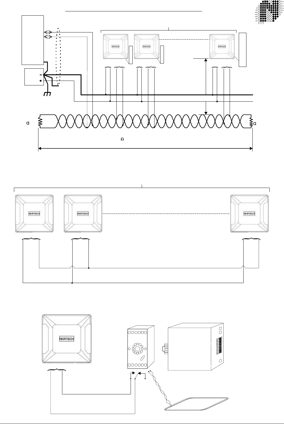
RS485
CONTROLLER
Data “A”
Data “B”
GND
Earth Ground
Power
Supply
120
TERMINATION
RESISTOR
120
TERMINATION
RESISTOR
-VE
+VE
A
B
A
B
Maximum
Stub Length
= 1 meter
Note 1: Refer to RS485
Addressing in section 4.3.1
See Note *1
See Note *1
A
A
A
B
B
B
COMMUNICATIONS CABLE MUST BE A TWISTED PAIR
MAXIMUM DISTANCE 1200 METERS (4000 FEET)
AUTOTAG-P BASE STATION “RS485” MULTIDROP CONNECTION DIAGRAM
THE INSTALLER MUST ENSURE THAT THE 120 TERMINATION RESISTORS ARE INSTALLED AT THE ENDS OF THE CABLE
Maximum number of readers = 32
5 Way
5 Way
5 Way
4 4 45 5 56 6 6
CN7 CN7 CN7
5
5
5

708UM0210-01 October 1999 Autotag-P User Manual Page: 32 of 33
CONNECTING EXTERNAL INDICATORS
DRIVING THE EXTERNAL INDOCATORS FROM AN ACCESS CONTROLLER
+
Power
Supply
-
BASE STATION
CN5-2 Green OUT
CN5-3 Red OUT
CN5-1 GND
Vmax = 30V
RED GREEN
Imax = 100mA
Imax = 100mA
BASE STATION
CN5-5 Red IN
CN5-4 Green IN
CN5-1 GND
ACCESS
CONTROLLER
Red OUT
Green OUT
GND
708UM0210-01 October 1999 Autotag-P User Manual Page: 33 of 33
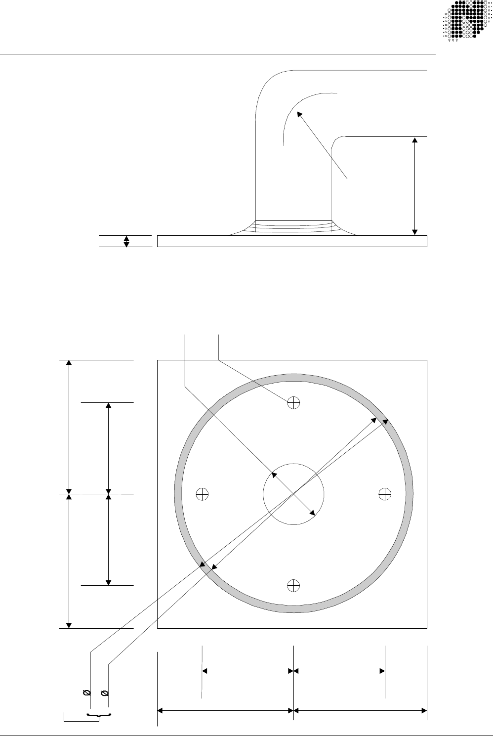
APPENDIX B – GOOSENECK MOUNTING PLATE
25 mm hole
for cables
All dimensions in millimeters
55 min 55 min
35.7 35.7
55
min
55
m
in
35.7
35.7
4 holes taped M4
98
92
25 - 50 mm
ID pipe
R
Smallest bend for pipe
diameter selected
Greater than 70 mm
Weld Fillet
4 mm
“O” ring seal
mating area