Nortech ATR434P Autotag Base Station User Manual install
Nortech International (PTY) LTD Autotag Base Station install
Nortech >
Contents
- 1. user manual
- 2. installation guide
installation guide
AUTOTAG-P BASE-STATION (ATR430P Series) INSTALLATION GUIDE
This guide covers the following units:
ATR431P 115V AC Base-Station Unit
ATR432P 230V AC Base-Station Unit
ATR434P 12-24V DC Base-Station Unit
1. EQUIPMENT REQUIRED
3mm Allen key M4 x 20mm machine screws Power cable
3mm flat screwdriver M4 nuts Screened Communications Cable
Side-cutters M4 washers (wide)
2. GENERAL DESCRIPTION
The base-station is a robust, weatherproof device capable of being mounted outdoors and
withstanding wide temperature / humidity ranges (-40°C to +70°
C, 0 - 98% RH). The casing is
constructed of an ABS plastic, which is impact- and UV-resistant. O-ring seals are
incorporated to ensure minimal ingress of water and dust. (Cable access is via knockouts
in
the base.) Access to the electronics is via screws hidden behind clip-in panels on the front
cover.
The unit may
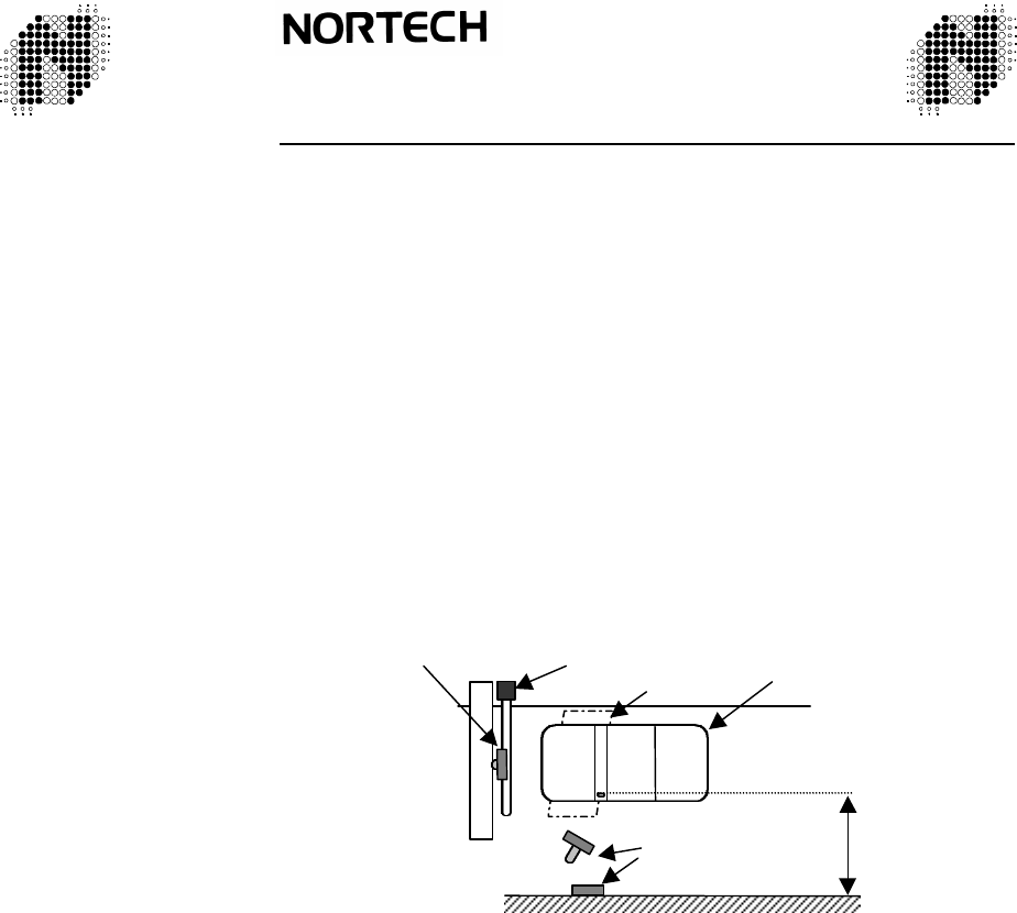
be either wall, pole or gantry mounted. It must be positioned so that it ‘looks into’
the vehicle.
Figure 1. Positioning
708LF0211-01 October 1999 Autotag-P Base-Station Installation Leaflet Page 1 of 8
8 m max.
Pole and wall Mount
Loop
Boom
Vehicle
Nortech International (Pty) Ltd
P O Box 4099 32A Wiganthorpe Road
Willowton Hub Pietermaritzburg
Pietermaritzburg 3201 South Africa
3200 South Africa Reg No. 98/1095
Tel: (033) 345 3456 Int Tel: +27 33 345 3456
Fax: (033) 394 6449 Int Fax: +27 33 394 6449
Email: mkt@nortech.co.za URL: www.nortech.co.za
708LF0211-01 October 1999 Autotag-P Base-Station Installation Leaflet Page 8 of 8
3. MOUNTING
Wall mounting:
Wall mounting is possible when the wall is within the specified range of the furthest side of the
vehicles to be monitored. The presence of metal re-inforcing in the wall has negligible effect on
the operation of the base-station.
1.
Determine the area in which the unit must detect. The base-station unit should be placed
facing the middle of this area (Figure 1)
2.
Unclip the two screw covers. Remove screws and front cover.
3.
Knockouts are provided on the base. Remove the appropriate knockouts, including that of
the cable access hole.
4.
Route power and communications cables through the cable access hole.
5.
Bolt base to wall via knockouts.
6.
Connect cables according to wiring diagram (see Section 3).
7.
Before applying power: Set the DIP switches according to the type of installation required.
If the ‘triggered’ setting is to be used, ensure the arming input is connected and that the
trigger system (e.g. loop detector) is functioning.
8.
Apply power. The RED LED should be illuminated.
9.
Holding a tag in front of the unit should cause the GREEN LED to flash and a beep to be
heard. This indicates that the base-station is receiving code from the tag.
NB:
The PCB does NOT need to be unscrewed from the front cover at any point. Doing so will
result in the warranty being voided.
Pole or gantry mounting:
1.
When mounting on a pole, ensure that the flange has a minimum diameter of 120 mm
2.
A hole in the centre of the flange with min. diameter of 30 mm will allow for hidden cable
access.
3.
Ensure that the unit faces the window area of the vehicles to be monitored.
4.
Mounting instructions are the same as for the above.
6. FCC REGULATIONS
When this system is used in the United States of America, only the following
models may be used:
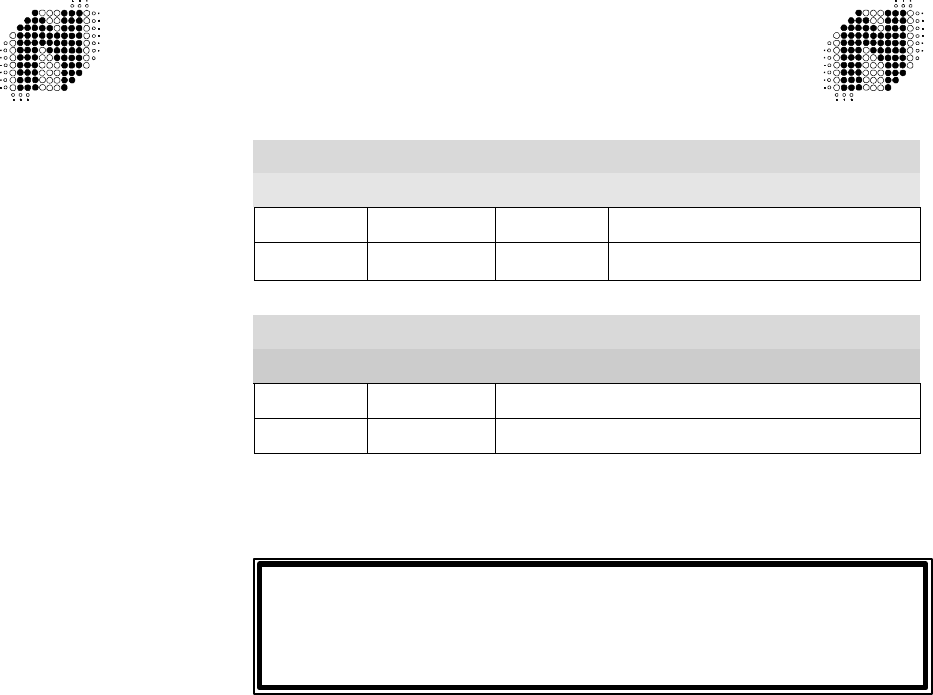
AUTOTAG-P BASE STATION MODELS
FT Number Part Number Voltage Protocol
708FT0233 ATR434P-C2 12-24V DC Clock & Data / Wiegand and RS-232
708FT0234 ATR434P-C2 12-24V DC Clock & Data / Wiegand and RS-232
(McGann)
AUTOTAG-P TRANSPONDER MODELS
FT Number Part Number Model
708FT0210 AT430P Programmable Tag
708FT0211 AT430P Programmable Tag (McGann)
User in the United States of America.
Please note the following important caution:-
708LF0211-01 October 1999 Autotag-P Base-Station Installation Leaflet Page 2 of 8 708LF0211-01 October 1999 Autotag-P Base-Station Installation Leaflet Page 7 of 8
Changes or modifications to this product not expressly approved by
Nortech International (Pty) Ltd, in writing, could void the user’s authority
to operate the product.
If there is more than one Base-Station in proximity to another, it is not
desirable for multiple Base-Stations to read the same tag. The ID’s of the
base stations must be set to different values. The ID’s are set with
dip-switch
SW1, allowance has been made for 16 different ID’s.
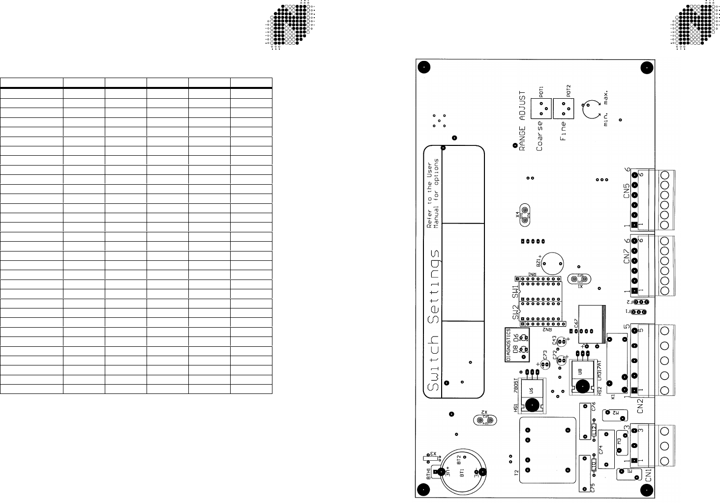
Dip Switch 1 Configuration SW1:
Address/ID SW1-5 SW1-4 SW1-3 SW1-2 SW1-1
0ON ON ON ON ON
1ON ON ON ON OFF
2ON ON ON OFF ON
3ON ON ON OFF OFF
4ON ON OFF ON ON
5ON ON OFF ON OFF
6ON ON OFF OFF ON
7ON ON OFF OFF OFF
8ON OFF ON ON ON
9ON OFF ON ON OFF
10 ON OFF ON OFF ON
11 ON OFF ON OFF OFF
12 ON OFF OFF ON ON
13 ON OFF OFF ON OFF
14 ON OFF OFF OFF ON
15 ON OFF OFF OFF OFF
16 OFF ON ON ON ON
17 OFF ON ON ON OFF
18 OFF ON ON OFF ON
19 OFF ON ON OFF OFF
20 OFF ON OFF ON ON
21 OFF ON OFF ON OFF
22 OFF ON OFF OFF ON
23 OFF ON OFF OFF OFF
24 OFF OFF ON ON ON
25 OFF OFF ON ON OFF
26 OFF OFF ON OFF ON
27 OFF OFF ON OFF OFF
28 OFF OFF OFF ON ON
29 OFF OFF OFF ON OFF
30 OFF OFF OFF OFF ON
31 OFF OFF OFF OFF OFF
Further literature on Autotag:
Autotag-P User Manual
708UM0210
Autotag-P Tag Installation Guide
708LF0210
Autotag-P Data Sheet
708DS0210
Autotag-P Programming Station User Manual
708UM0201
4. LAYOUT OF MAIN BOARD
708LF0211-01 October 1999 Autotag-P Base-Station Installation Leaflet Page 6 of 8
708LF0211-01 October 1999 Autotag-P Base-Station Installation Leaflet Page 3 of 8
5
.WIRING DETAIL
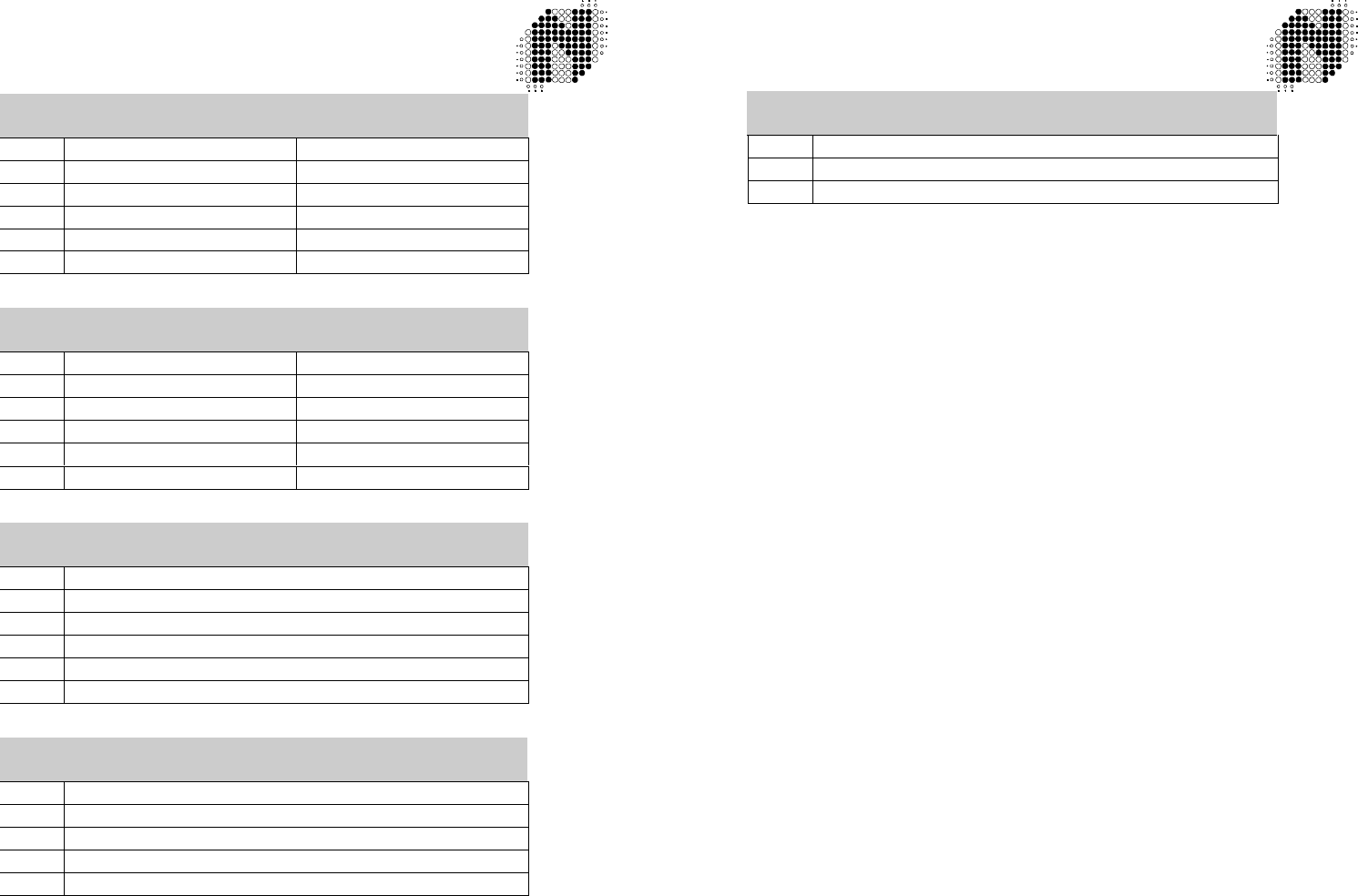
CN7 6 Way Pluggable Screw Terminal
PIN Wiegand Function Clock & Data Function
1Triggered Input Triggered Input (Arming)
2Not Used Card Present
3DATA 1 Data
4DATA 0 Clock
5As per table below As per table below
6As per table below As per table below
CN7 6 Way Pluggable Screw Terminal
PIN RS232 Function RS485 Function
1As per table above As per table above
2As per table above Not Used
3As per table above RS485 TX Active
4As per table above Not Used
5RS232 TX RS485 B
6RS232 TX RS485 A
CN5 6 Way Pluggable Screw Terminal
PIN FUNCTION
1Signal Ground
2External Indicator Output – Green
3External Indicator Output – Red
4External Indicator Input – Green
5External Indicator Input – Red
6SYNC
CN2 5 Way Pluggable Screw Terminal
PIN FUNCTION
1Relay Normally Open
2Relay Normally Closed
3Relay Common
4DC Power In Negative
5DC Power In Positive
CN1 # Way Pluggable Screw Terminal
PIN FUNCTION
1Mains Power Live
2Mains Power Safety Earth
3Mains Power Neutral
Note:Any additional wires used for GROUND connections should be connected to CN5 Pin 1.
Connecting the Base-station to a controller:
Wiegand:
Connect the following lines: CN7 Pin 4 (DATA0), CN7 Pin 3 (DATA1) and CN5 Pin
1 (GND) to the corresponding terminals on the controller. Ensure that switch SW2-
3 is ON.
Clock & Data:
Connect the following lines: CN7 Pin 4 (Clock), CN7 Pin 3 (Data), CN7 Pin 2 (Card
Present) and CN5 Pin 1 (GND) to the
corres-ponding terminals of the controller.
Ensure that SW2-3 is OFF.
RS232: This feature is only available on the RS232 m
odel. Connect CN7 Pin 5 (RS232 TX)
to the receive pin of the controller. Connect CN7 Pin 6 (RS232 RX) to the transmit
pin of the controller. Connect CN5 Pin 1 (GND) to the signal GND Pin of the
controller.
RS485: This feature is only available on the R
S485 model. Connect the following lines:
CN7 Pin 6 (RS485 A), CN7 Pin 5 (RS485 B) and CN5 Pin 1 (GND) to the
corresponding terminals of the controller. Ensure that each base station has a
unique address by setting switches SW1-1 through SW1-5.
Connecting the Base-station to a triggering device:
This is done when the Base-station is to operate in ‘Triggered’ mode. A vehicle detector
positioned directly in front of the Base-station unit is used to trigger operation.
The vehicle detector can be a loop detector, capacitive detector or any other unit capable of
providing a CONTINUOUS
relay closure whilst a vehicle is present. In the case of a loop detector
this requires that the unit is configured for PERMANENT PRESENCE.
Connect CN7 Pin 1to the N/O relay output of the triggering device, and CN5 Pin 6 to the RELAY
COMMON connection.
Operating multiple Base-Stations in proximity to one another:
When two or more Base-Station units are operated in proximity to one another they may cause
mutual interference if not synchronised. Synchronisation ensures that their transmissions do not
interfere with one another. To synchronise the units, connect the SYNC lines (CN5 Pin 6) and
GND (CN5 Pin 1) on the 6-pin power connectors to the corresponding pins on all units (i.e. Pin 6
to Pin 6, Pin 1 to Pin 1).
708LF0211-01 October 1999
Autotag-P Base-Station Installation Leaflet Page 4 of 8 708LF0211-01 October 1999 Autotag-P Base-Station Installation Leaflet Page 5 of 8