Nortech PD230TD236 Vehicle Detector User Manual 302UM0017 01a PD230 Enh NewHousing NoApprovalsPage
Nortech International (PTY) LTD Vehicle Detector 302UM0017 01a PD230 Enh NewHousing NoApprovalsPage
Nortech >
User Manual

Nortech International (Pty) Ltd
PO Box 4099 32A Wiganthorpe Road
Willowton Hub Pietermaritzburg
Pietermaritzburg 3201 South Africa
3200 South Africa Reg. No. 98/1095
Tel: (033) 345 3456 Int. Tel: +27 33 345 3456
Fax: (033) 394 6449 Int Fax: +27 33 394 6449
E-mail: mkt@nortech.co.za URL: www.nortech.co.za
PD230 Enhanced
Vehicle Detector
USER MANUAL
NORTECH INTERNATIONAL (PTY) LTD
All rights reserved.
Copyright © 2009
Document No.: 302UM0017_01a
Date of issue: August 2010
This document is for information only and unless otherwise indicated it is not to form part of any contract.
In accordance with the manufacturer’s policy of continually updating and improving design, specifications contained
herein are
subject to alterations without notice.

302UM0017 Rev 01 PD230 Enhanced Detector User Manual Page 2 of 37
Table of Contents
1. INTRODUCTION........................................................................................................................5
2. TECHNICAL DATA ....................................................................................................................6
2.1 Functional Data..........................................................................................................................6
2.2 Electrical Data............................................................................................................................6
2.3 Environmental Data....................................................................................................................7
2.4 Mechanical Data ........................................................................................................................8
2.5 Approvals ...................................................................................................................................8
3. OPERATING INSTRUCTIONS..................................................................................................9
3.1 Hardware Set-up........................................................................................................................9
3.2 Switch Setting Selections...........................................................................................................9
3.2.1 Frequency Switch..............................................................................................................9
3.2.2 Sensitivity ..........................................................................................................................9
3.2.3 Automatic Sensitivity Boost.............................................................................................10
3.2.4 Presence Time ................................................................................................................10
3.2.5 Pulse / Presence .............................................................................................................10
3.2.6 Reset Switch ...................................................................................................................10
3.3 Internal Link Selection..............................................................................................................11
3.4 Power Fail (Option) ..................................................................................................................11
3.5 Front Panel Indicators..............................................................................................................11
4. PRINCIPLE OF OPERATION..................................................................................................13
4.1 Detector Tuning........................................................................................................................13
4.2 Detector Sensitivity ..................................................................................................................13
4.3 Modes of Operation .................................................................................................................14
4.3.1 Presence Mode ...............................................................................................................14
4.3.2 Pulse Mode......................................................................................................................14
4.3.3 AB Logic Presence Mode (Barrier Operation) ................................................................15
4.3.4 AB Logic Pulse Mode (Counting Logic) ..........................................................................17
4.4 Response Times ......................................................................................................................19
5. INSTALLATION GUIDE ...........................................................................................................20
5.1 Product Safety Requirements..................................................................................................20
5.2 Operational Constraints ...........................................................................................................20
5.2.1 Environmental Factors to Consider.................................................................................20
5.2.2 Crosstalk..........................................................................................................................21
5.2.3 Reinforcing ......................................................................................................................21
5.3 Loop and Feeder Material Specification ..................................................................................21
5.4 Sensing Loop Geometry ..........................................................................................................22
5.5 Loop Installation.......................................................................................................................22
6. CONFIGURATION...................................................................................................................25
6.1 PD231 Enhanced Detector : English .......................................................................................25
6.2 PD232 Enhanced Detector: English ........................................................................................26
6.3 PD234 Enhanced Detector: English ........................................................................................26
7. APPLICATIONS.......................................................................................................................27
8. CUSTOMER FAULT ANALYSIS .............................................................................................28
8.1 Fault Finding ............................................................................................................................28
8.2 DU100 – Detector Diagnostic Unit...........................................................................................29
8.2.1 Interpretation of the DU 100 readings.............................................................................29
8.2.1.1 Frequency.........................................................................................................................29
8.3 Functional Test.........................................................................................................................31
APPENDIX A - FCC ADVISORY STATEMENT .............................................................................32
APPENDIX B – INSTALLATION OUTDOORS ...............................................................................33
Appendix B.1 IEC 60950-22:2005 – Outdoor cabinet ..............................................................33
Appendix B.2 IEC 60950-22:2005 - Northern Europe ..............................................................33

302UM0017 Rev 01 PD230 Enhanced Detector User Manual Page 3 of 37
Appendix B.3 IEC 60950-1:2005 – Overvoltage Category.......................................................33
APPENDIX C - REQUEST FOR TECHNICAL SUPPORT FORM .................................................34

302UM0017 Rev 01 PD230 Enhanced Detector User Manual Page 4 of 37
WARNING: 1. THIS UNIT MUST BE EARTHED !
WARNING: 2. DISCONNECT POWER BEFORE
WORKING ON THIS UNIT !
WARNING: 3. INSTALLATION AND OPERATION
BY SERVICE PERSONNEL ONLY !
WARNING: 4. NO USER SERVICEABLE PARTS INSIDE.
ONLY SERVICE PERSONNEL MAY OPEN THE
UNIT TO CHANGE INTERNAL SETTINGS!
WARNING: 5. Always suspend traffic through the barrier area
during installation and testing that may result in
unexpected operation of the barrier
WARNING: 6. USA
FCC Advisory Statement – Refer to Appendix A at
the end of this document.
WARNING: 7. Europe
Disposing of the product.
This electronic product is subject to the
EU Directive 2002/96/EC for Waste
Electrical and Electronic Equipment
(WEEE). As such, this product must not
be disposed of at a local municipal
waste collection point. Please refer to
local regulations for directions on how
to dispose of this product in an
environmental friendly manner.
302UM0017 Rev 01 PD230 Enhanced Detector User Manual Page 5 of 37
1. INTRODUCTION
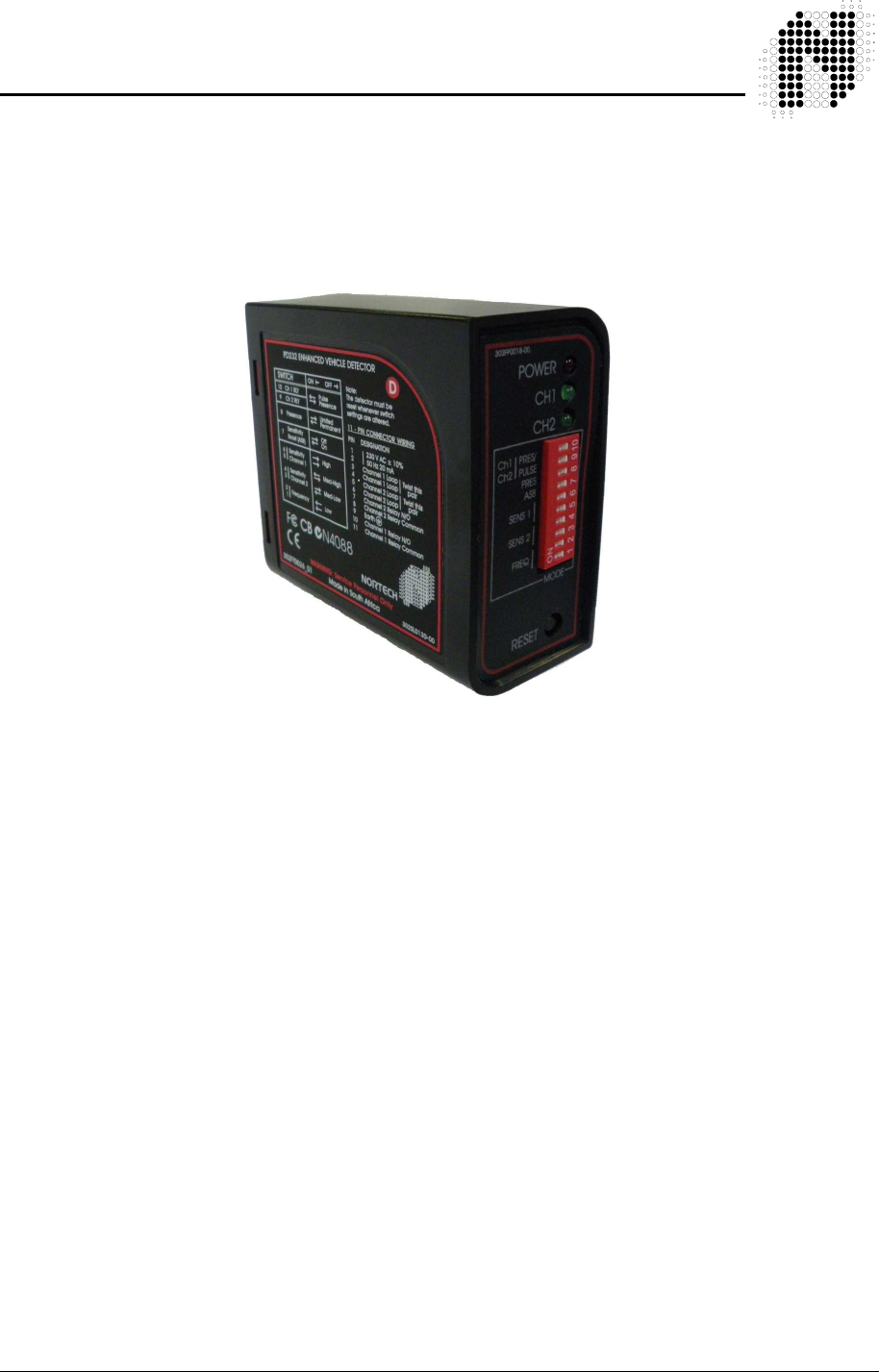
The “PD230 Enhanced Two Channel Inductive Loop Vehicle Detector” is a dual
channel microprocessor based detector designed specifically for parking and vehicle access control
applications. The PD230 Enhanced detector has been designed using the latest technology in order
to meet the requirements of a vast number of parking applications in terms of operating conditions.
A number of internal functional options are available to the user.
The primary function of the detector is to detect vehicle presence by means of an inductance
change caused by the vehicle passing over a wire loop buried under the road surface.
The detector has been designed around the popular PD130 series of single channel detectors for
ease of installation and convenience. The various modes are selected by changing the position of
switches on the front of the unit.
The detector oscillator is multiplexed to eliminate any possibility of crosstalk between the loops
connected to the detector.
The switches allow for different loop frequency settings, sensitivity settings and mode settings.
The unit has a number of internally selectable options for configuration of the relay outputs.
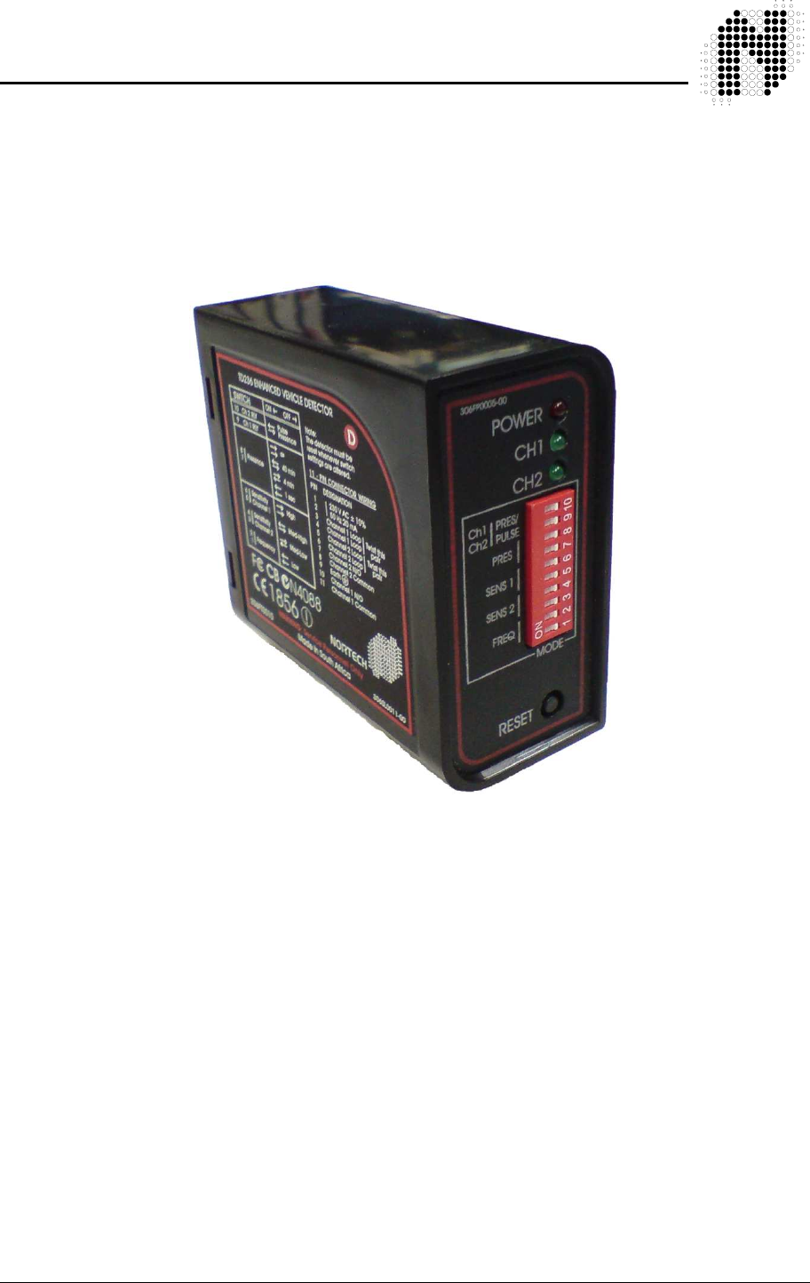
The PD230 Enhanced 2 Channel Vehicle Detector provides visual outputs (LED) on the front of the
enclosure and relay change-over contacts at the 11 pin connector at the rear of the enclosure. The
power LED indicates that the unit has been powered. The channel status LED’s below indicate that
a vehicle is present over the loop and when there is a fault on the loop. The Presence relays are
normally fail-safe and will close on a vehicle detect, loop failure or in the event of a power failure.
Available is an additional Power-fail function which enables a short (of up to ten minutes) power-fail,
to have no effect on the operation of the detector when power is restored. The detector will revert to
the same state as prior to power failure, when power is restored.
For additional information refer to the following documents:
Data Sheet - PD230 Enhanced 2 Ch Vehicle Detector Document No. 302DS0002
Installation Leaflet Document No. 879LF0006
Diagnostic Unit DU100 User Manual Document No. 895UM0001
2/4 Ch Vehicle Detector Installation Guide Document No. 879LF0006

302UM0017 Rev 01 PD230 Enhanced Detector User Manual Page 6 of 37
2. TECHNICAL DATA
2.1 Functional Data
Tuning Fully automatic
Self-tuning range 20 to 1000 µH
Sensitivity Four step switch selectable:
High 0.02% ∆ L/L
Medium-High 0.05% ∆ L/L
Medium-Low 0.10% ∆ L/L
Low 0.50% ∆ L/L
Frequency Four step selectable:
Frequency dependent on loop size
Automatic Sensitivity Boost Switch selectable
Modes Output relays may operate in the Presence ( fail-safe ),
Pulse or Direction logic modes
Presence Time Switch selectable:
Limited presence
Permanent presence
Pulse Output Duration 150/250 millisecond options
Response Times 100 milliseconds
Drift Compensation Rate Approx. 1% ∆ L/L per minute
Visual Indication 1 x Power LED - Red
2 x Channel Status LEDs - Green
Relay Outputs 2 x Relays, User Configurable as Presence or Pulse outputs,
Normally Open (N/O) contacts
(Opto-Isolated Outputs are available on request. MOQ applies)
Reset Reset by push button on front of enclosure
Surge Protection Loop isolation transformer, gas discharge tubes,
and Zener diode clamping on loop input
Power Fail (Option) 10 minutes memory retention of detector state on power failure.
2.2 Electrical Data
Power requirements 120V AC ± 10% 48 to 62Hz (PD231 models)
230V AC ± 10% 48 to 62Hz (PD232 models)
PD231 and PD232 models: 1.5 VA Maximum at 230V
12V - 10% to 24V + 10% DC/AC 48 to 62Hz (PD234 models)
302UM0017 Rev 01 PD230 Enhanced Detector User Manual Page 7 of 37
PD234 models: 1 VA Maximum at 12V
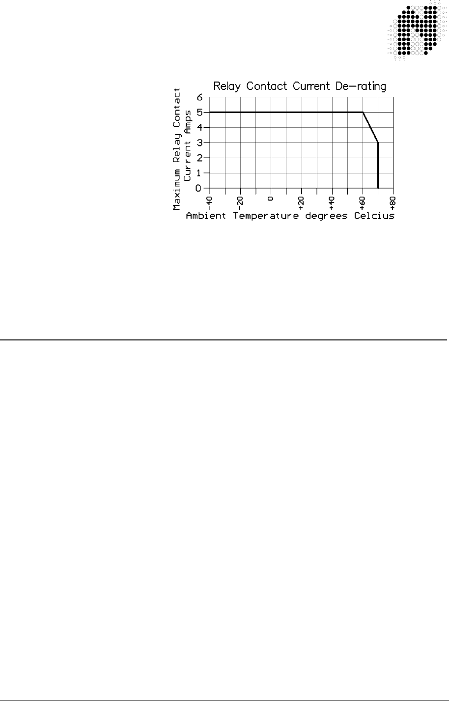
Relay Contact Rating 2 x Relays rated - 5A @ 230 VAC
For ambient temperatures above 60 °C De-rate the
relay maximum current as per graph below
Opto-Isolated Output rating 33 V 50 mA
Note - Opto-Isolated Outputs are available on request. MOQ
applies
2.3 Environmental Data
Storage Temperature -40°C to +85°C
Operating Temperature -40°C to +70°C
Humidity Up to 95% relative humidity without condensation
Circuit Protection Conformal coating over the PCB and all components
IP Rating IP 30. - This product MUST be installed in an enclosure
302UM0017 Rev 01 PD230 Enhanced Detector User Manual Page 8 of 37
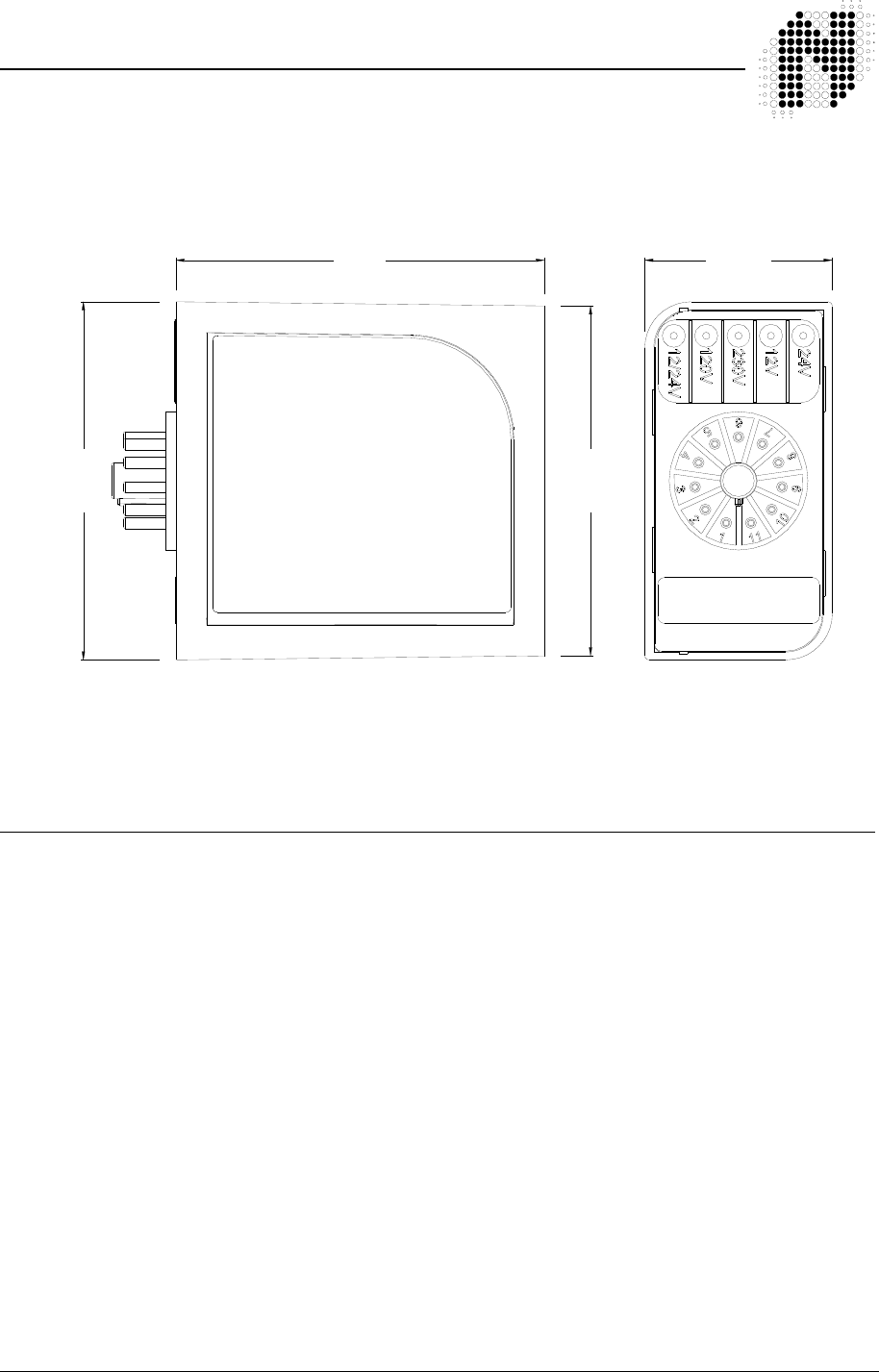
2.4 Mechanical Data
Housing material ABS blend
Mounting Position Shelf or DIN rail mounting
Connections 11-pin submagnal type ( JEDEC No. B11– 88 )
Size of Housing 78mm ( High ) x 41mm ( Wide ) x 80mm ( Deep )
2.5 Approvals
C.E. Regulations EN 301 489-3 Equipment Type: III
Class of Equipment: 2
EN 50293 Performance Criteria B
Safety: IEC / EN 60950-1
80 mm
75.9 mm
77.7 mm
40.6 mm
302UM0017 Rev 01 PD230 Enhanced Detector User Manual Page 9 of 37
3. OPERATING INSTRUCTIONS
3.1 Hardware Set-up
The PD230 Enhanced dual channel parking detector is designed to be shelf or DIN rail mounted
with the controls and visual indicators at the front and wiring at the rear of the enclosure.
The power, loop and relay outputs are all connected to the single 11-pin plug, which is mounted at
the rear of the enclosure.
3.2 Switch Setting Selections
3.2.1 Frequency Switch
Where more than one detector is used at the same site, the
detectors must be set-up to ensure that there is no CROSSTALK
(interference) between adjacent loops connected to different
detectors.
For more information about crosstalk refer to section 5.2.2.
The frequency switches are the lower two switches, numbered 1
and 2. There are four frequency selections and are set as follows:
The frequency switches allows the operating frequencies of the
detector to be shifted higher or lower depending on the switch
setting.
The operating frequency of the detector channel is determined by:
Inductance of the loop and feeder cable
Detector frequency switch settings
The operating frequency of the detector channel increases as the
loop inductance decreases and vice versa.
The inductance of the loop and feeder cable is determined by:
Size of the loop
Number of turns in the loop
Length of feeder cable
As a general rule, the detector connected to the inductive loop with the greatest inductance should
be set to operate at the lowest frequency.
When the frequency switch setting is altered, the operating frequency of both detector channels will
shift. Because the unit has a common oscillator and the multiplexer connects the loops alternatively
to this oscillator.
3.2.2 Sensitivity
The sensitivity of the detector allows the detector to be selective as to the change of inductance
necessary to produce an output. There are four sensitivity selections and are set as follows: -
S1 S2 Frequency Setting
Off Off High frequency
Off On Medium-High frequency
On Off Medium-Low frequency
On On Low frequency

302UM0017 Rev 01 PD230 Enhanced Detector User Manual Page 10 of 37
Channel1 Channel 2
S6 S5 S4 S3
Off Off Off Off High
On Off On Off Medium-High
Off On Off On Medium-Low
On On On On Low
3.2.3 Automatic Sensitivity Boost
Automatic sensitivity boost is a mode which alters the undetect level of the detector. This mode is
selected by switch No. 7 on the front of the enclosure and is set as follows: -
S7
Off Disabled
On Enabled
Automatic sensitivity boost causes the sensitivity to be boosted to a maximum on detection of the
vehicle, and maintained at this level during the presence of the entire vehicle over the loop. When
the vehicle departs the loop and detection is lost the sensitivity reverts to the pre-selected level.
3.2.4 Presence Time
The presence time may be set to permanent presence or to limited presence. In permanent
presence mode the detector will continuously compensate for all environmental changes whilst there
is a vehicle present over the loop. In limited presence mode there will be a finite time that the
detector will remain in detect. This time is dependent on the change of inductance that the vehicle
caused. The presence mode is set with switch No. 8 and is set as follows: -
S8
Off Limited Presence
On Permanent Presence
3.2.5 Pulse / Presence
The channel’s relay may be set to either Pulse Mode or Presence Mode with switches No. 9 & No.
10 as shown in the table below: -
Channel1 Channel 2
S10 S9
Off Off Presence
On On Pulse
3.2.6 Reset Switch
The detector automatically tunes to the inductive loops connected to it when power is applied,
whether on initial installation or after any break in the power supply. Should it be necessary to
retune the detector, as may be required after the changing of any switch selections or after moving
the detector from one installation to another, momentary operation of the RESET switch will initiate
the automatic tuning cycle.
302UM0017 Rev 01 PD230 Enhanced Detector User Manual Page 11 of 37
3.3 Internal Link Selection
WARNING - ONLY SERVICE PERSONNEL MAY OPEN THE UNIT
TO CHANGE INTERNAL SETTINGS!
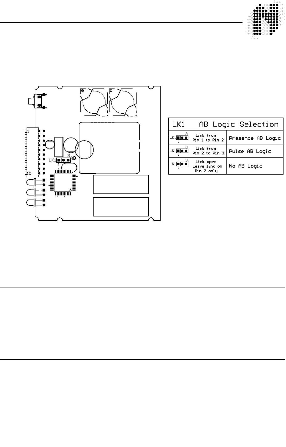
There is one 3 way link located inside the PD230 Enhanced detector housing, which is used to alter
the mode of operation of the detector. The link has been placed inside the unit to avoid incorrect
operation due to selection by an unauthorised operator.
For a description of the AB Logic mode refer to section 4.3 “Modes of Operation” below
For the PD230 Enhanced parking detector, the default setting for both channel output relays is
presence mode (Front panel switches 9 & 10 OFF) with no AB logic (i.e. no jumper on LK1).
3.4 Power Fail (Option)
Power-Fail-Option is available on request. MOQ applies
The detector (with Power-Fail Option) is able to retain the output state for a power failure of not
greater than 10 minutes. Thus, when the power is restored, the detector will not re-tune but return to
the detect state prior to the power failure. If a vehicle was on the loop during power failure, it will
remain detected when power is restored.
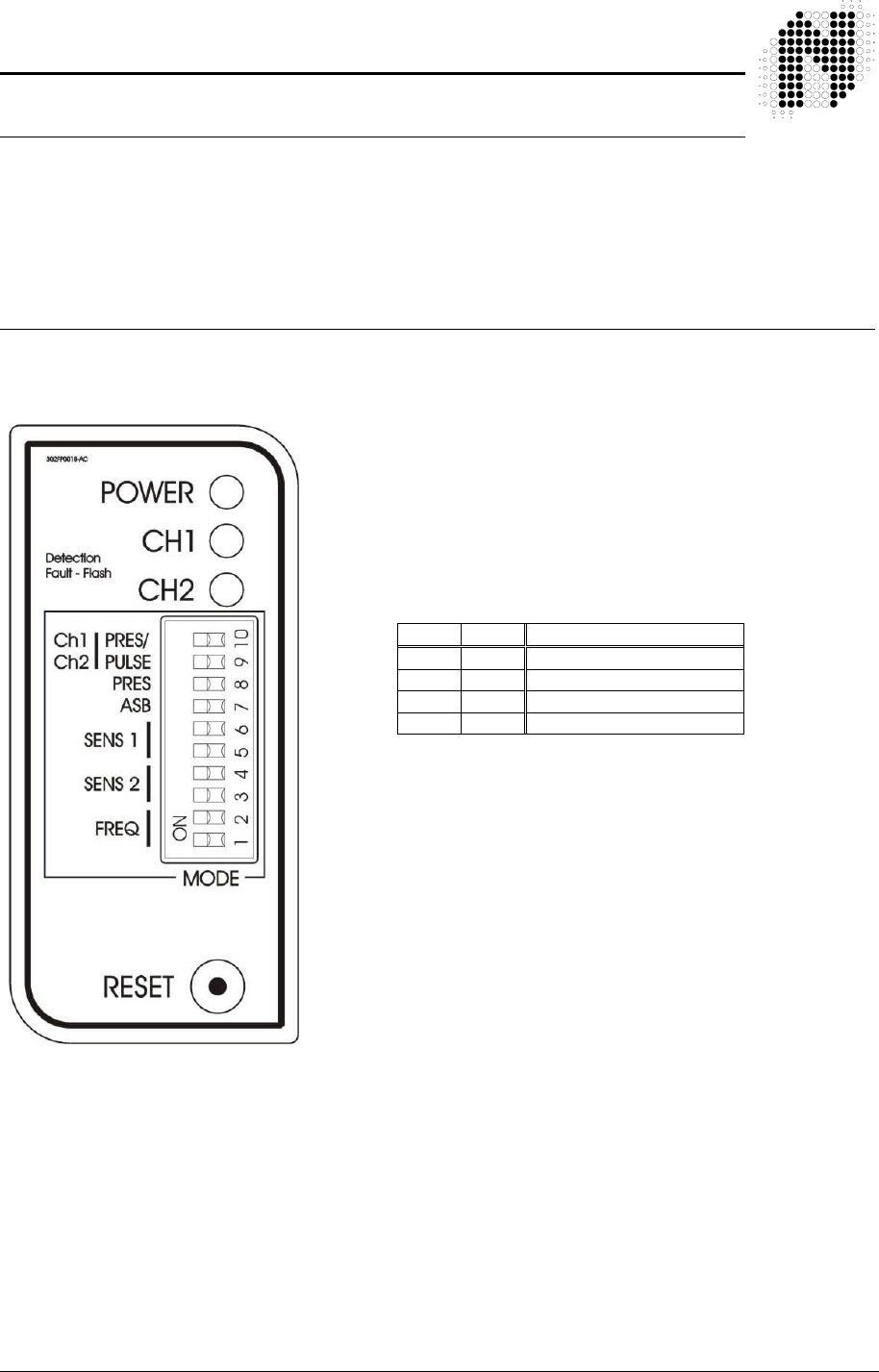
3.5 Front Panel Indicators
While the detector is tuning, the Channel LED will indicate the “mode” status of the detector.
i) Any Channel output operating in the presence or pulse modes will come on and extinguish when
the system is tuned.
ii) When the AB Logic mode is selected, the Channel LED’s will alternatively flash slow and
extinguish when the system is tuned.
If a loop fault exists the Channel LED will come on and flash indicating a fault. If the fault is self-
healing the detector will continue to operate and the LED will continue to show the historical fault.
The detector must be reset or power removed to clear the historical fault information.

302UM0017 Rev 01 PD230 Enhanced Detector User Manual Page 12 of 37
The channel LED will also glow whenever a vehicle is detected passing over the
inductive loop.
The Power LED at the top of the unit will remain on to indicate that the unit is powered. This LED is
also used as the link to the diagnostic unit ( DU100 ).

302UM0017 Rev 01 PD230 Enhanced Detector User Manual Page 13 of 37
4. PRINCIPLE OF OPERATION
The inductive loop vehicle detector senses the presence of a vehicle over an area
defined by a loop of two or more turns of wire laid under the road or pavement
surface. This loop of wire is connected to the detector by a pair of wires called a loop feeder.
A vehicle passing over a sensing loop causes a small reduction in the inductance of the loop, which
is sensed by the detector. The sensitivity of detection is adjustable to accommodate a wide range of
vehicle types as well as different loop and feeder combinations.
Upon detection of a vehicle passing over the loop the detector operates its output relays which may
be used to indicate controls associated with the installation.
4.1 Detector Tuning
Tuning of the detector is fully automatic. The detector will re-tune if any of the following events
occur:- - When power is applied to the detector.
- A detector reset is initiated via the reset button.
- A detect of greater than 15% ∆ L/L occurs.
The detector will automatically tune each channel to its connected loop. The detector will tune to any
loop in the inductance range of 20 to 1000 micro henries.
This wide range ensures that all loop sizes and feeder combinations will be accommodated in the
tuning range of the detector.
Once tuned, any slow environmental change in loop inductance is fed to a compensating circuit
within the detector, which keeps the detector correctly tuned.
4.2 Detector Sensitivity
Sensitivity of the detection system is dependent on factors such as loop size, number of turns in the
loop, feeder length and the presence of metal reinforcing beneath the loop.
The nature of the application determines the required sensitivity, which may be adjusted by means
of the front panel controls.
Sensitivity levels on the PD230 Enhanced detector have been carefully optimised for parking and
vehicle access control applications. The detection of small, unwanted objects such as bicycles and
trolleys can be eliminated by selecting lower sensitivity levels, whilst high-bed vehicles and
vehicle/trailer combinations will not loose detection by using the Automatic Sensitivity Boost (ASB)
option.
ASB operates as follows. When ASB is disabled the undetect level is dependent on the sensitivity
setting of the detector. Hence as the detector is made less sensitive, the undetect level will be
302UM0017 Rev 01 PD230 Enhanced Detector User Manual Page 14 of 37
reduced accordingly. When the ASB is enabled the undetect level will always be the
same irrespective of the sensitivity setting and will be equivalent to the undetect
level when the sensitivity is on maximum setting.
4.3 Modes of Operation
The PD230 Enhanced Detector may be configured for any one of the following modes:
Presence Mode
Pulse Mode
AB Logic Presence Mode (Barrier Operation)
AB Logic Pulse Mode (Counting Logic)
4.3.1 Presence Mode
Link LK1 open
To set Channel 1 to Presence mode switch OFF switch 10
To set Channel 2 to Presence mode switch OFF switch 9
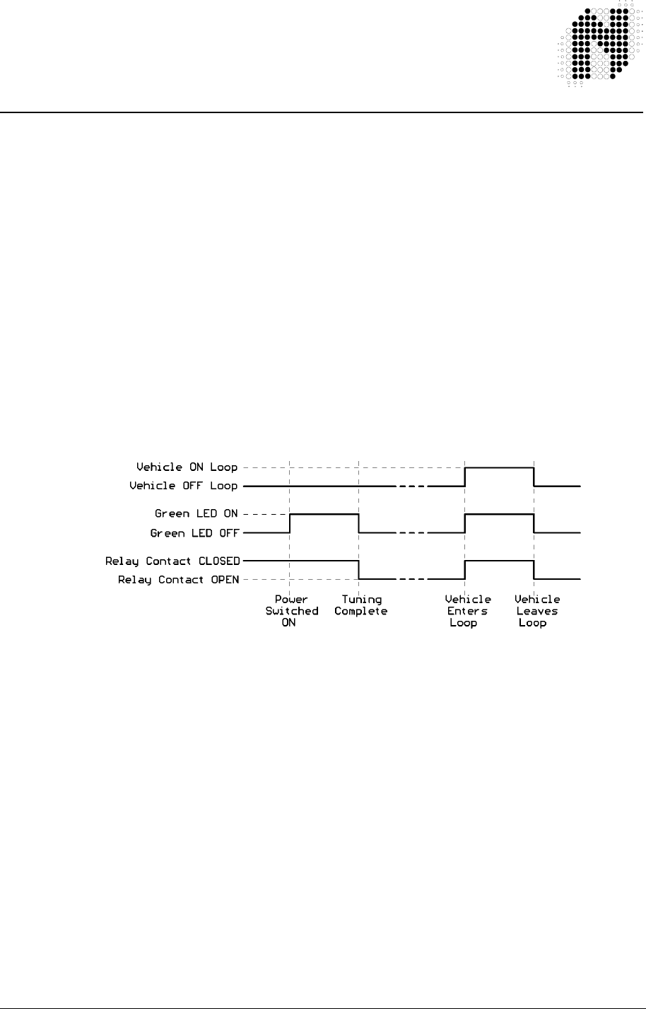
In the presence mode the detector channels operate independently
In the presence mode the detector will give a continuous output during the presence of a
vehicle over the inductive loop. As the detector is designed with the permanent presence
feature, the detector will indicate vehicle presence for an unlimited period of time.
The presence outputs are known as fail-safe outputs. This implies that in the event of a
power failure or loop failure the detector will give detect outputs. (Fail-Secure Presence
Mode is available on request. MOQ applies)
If permanent presence is not selected, then the detect time will be dependent on the change
of inductance. The presence time on the limited presence setting will be approximately 1
hour for an inductance change of 3% ∆ L/L.
4.3.2 Pulse Mode
Link LK1 open
To set Channel 1 to Pulse mode switch ON switch 10
To set Channel 2 to Pulse mode switch ON switch 9
In the pulse mode the detector channels operate independently.
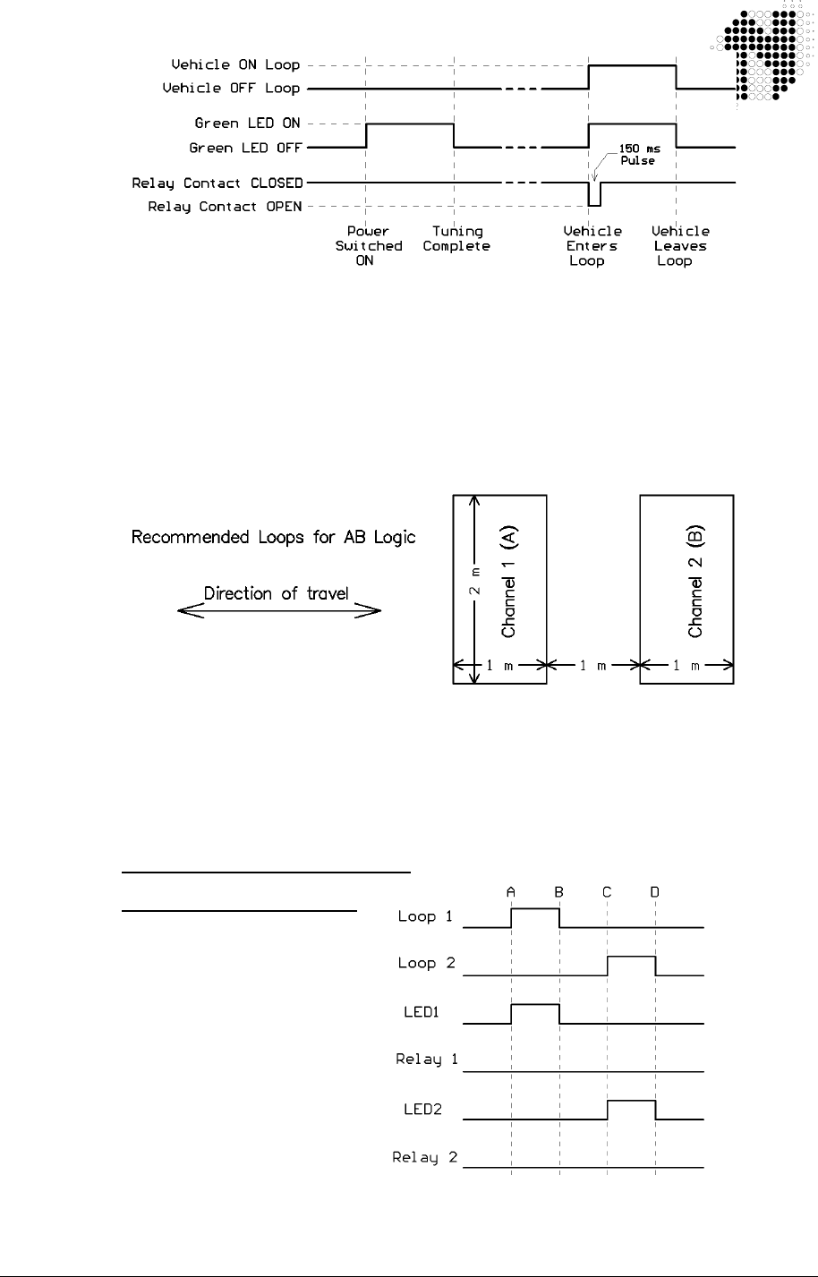
In the pulse mode the detector will give a pulse of 150 millisecond duration, when a vehicle
enters the loop (Pulse on Detect) (a pulse of 250 millisecond is available on request. MOQ
applies).
302UM0017 Rev 01 PD230 Enhanced Detector User Manual Page 15 of 37
(Pulse on un-detect is available on request. MOQ applies)
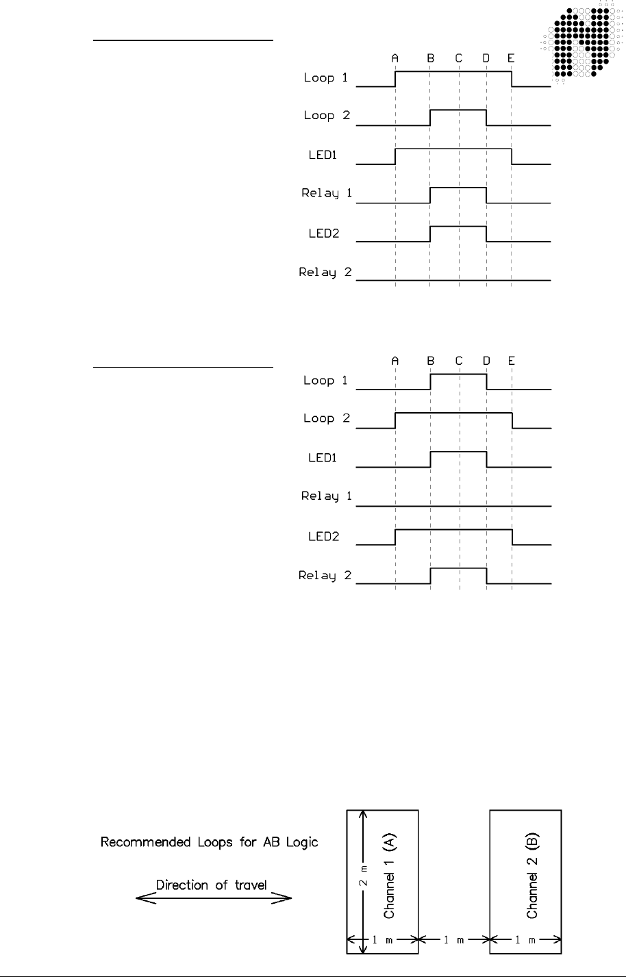
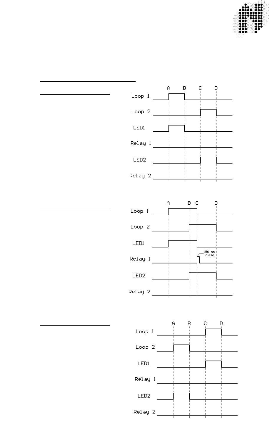
4.3.3 AB Logic Presence Mode (Barrier Operation)
Internal link LK1 shorted from Pin 1 to Pin 2. In this mode switches 9 & 10 are ignored.
AB LOGIC Presence Mode is a direction logic mode, and is capable of determining direction
of travel of a vehicle. Two loops are laid in the direction of travel to provide the input for this
mode.
If a vehicle enters Channel 1 Loop and then proceeds to Channel 2 Loop, Channel 1 relay
contacts will close for the duration of that the vehicle is over Channel 2 Loop.
If a vehicle enters Channel 2 Loop and then proceeds to Channel 1 Loop, Channel 2 relay
contacts will close for the duration of that the vehicle is over Channel 1 Loop.
Progress of a vehicle over the loops
Case 1:
(AB LOGIC Presence Mode)
Forward direction
A - Vehicle Enters Loop1
B - Vehicle Exits Loop 1,
C - Vehicle Enters Loop2,
D - Vehicle Exits Loop 2,
Typically caused by loops
being too far apart or very
small vehicles
302UM0017 Rev 01 PD230 Enhanced Detector User Manual Page 16 of 37
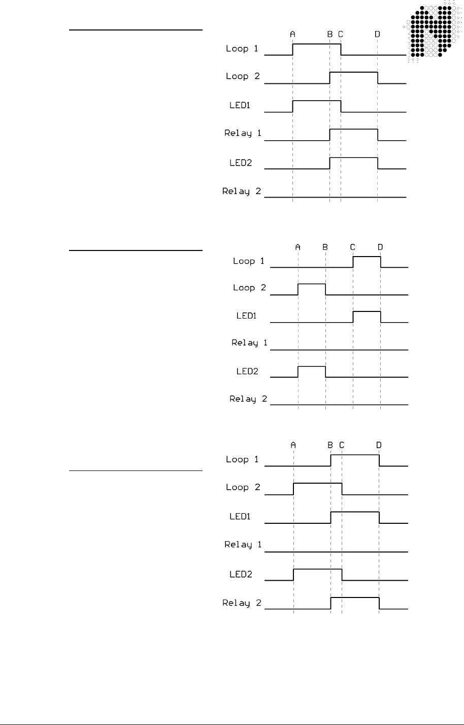
Case 2:
(AB LOGIC Presence Mode)
Forward direction
A - Vehicle Enters Loop1
B - Vehicle Enters Loop2
C - Vehicle Exits Loop 1
D - Vehicle Exits Loop 2
This is the correct forward
operation for Presence
AB Logic
Case 3:
(AB LOGIC Presence Mode)
Reverse direction
A - Vehicle Enters Loop2
B - Vehicle Exits Loop 2
C - Vehicle Enters Loop1
D - Vehicle Exits Loop 1
Typically caused by loops
being too far apart or very
small vehicles
Case 4:
(AB LOGIC Presence Mode)
Reverse direction
A - Vehicle Enters Loop2
B - Vehicle Enters Loop1
C - Vehicle Exits Loop 2
D - Vehicle Exits Loop 1
This is the correct reverse
operation for Presence
AB Logic
302UM0017 Rev 01 PD230 Enhanced Detector User Manual Page 17 of 37
Case 5:
(AB LOGIC Presence Mode)
Forward direction
A - Vehicle Enters Loop1
B - Vehicle Enters Loop2
C - Vehicle Starts to reverse
D - Vehicle Exits Loop 2
E - Vehicle Exits Loop 1
This case should not
happen but it does
occasionally
Case 6:
(AB LOGIC Presence Mode)
Reverse direction
A - Vehicle Enters Loop2
B - Vehicle Enters Loop1
C - Vehicle Starts to reverse
D - Vehicle Exits Loop 1
E - Vehicle Exits Loop 2
This case should not
happen but it does
occasionally
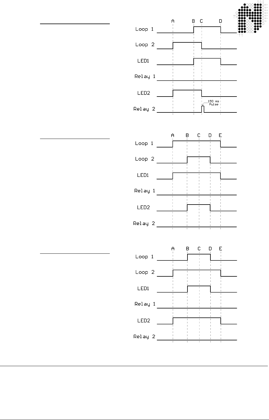
4.3.4 AB Logic Pulse Mode (Counting Logic)
Internal link LK1 shorted from Pin 2 to Pin 3. In this mode switches 9 & 10 are ignored.
AB LOGIC Pulse Mode is a direction logic mode, and is capable of determining direction of
travel of a vehicle. Two loops are laid in the direction of travel to provide the input for this
mode.
This mode is used to activate equipment requiring vehicle direction inputs such as automatic
fee collection equipment, vehicle counters, or warning devices in one-way systems.
302UM0017 Rev 01 PD230 Enhanced Detector User Manual Page 18 of 37
If a vehicle enters Channel 1 Loop and then proceeds to Channel 2 Loop, a
150 ms pulse will be issued on Channel 1 relay output as the vehicle leaves
Channel 1 Loop.
If a vehicle now enters Channel 2 Loop and then proceeds to Channel 1 Loop, a 150 ms
pulse will be issued on Channel 2 relay output as the vehicle leaves Channel 2 Loop.
Progress of a vehicle over the loops
Case 1:
(AB LOGIC Pulse Mode)
Forward direction
A - Vehicle Enters Loop1
B - Vehicle Exits Loop 1,
C - Vehicle Enters Loop2,
D - Vehicle Exits Loop 2,
Typically caused by loops
being too far apart or very
small vehicles
Case 2:
(AB LOGIC Pulse Mode)
Forward direction
A - Vehicle Enters Loop1
B - Vehicle Enters Loop2
C - Vehicle Exits Loop 1
D - Vehicle Exits Loop 2
This is the correct forward
operation for Pulse
AB Logic
Case 3:
(AB LOGIC Pulse Mode)
Reverse direction
A - Vehicle Enters Loop2
B - Vehicle Exits Loop 2
C - Vehicle Enters Loop1
D - Vehicle Exits Loop 1
Typically caused by loops
being too far apart or very
small vehicles
302UM0017 Rev 01 PD230 Enhanced Detector User Manual Page 19 of 37
Case 4:
(AB LOGIC Pulse Mode)
Reverse direction
A - Vehicle Enters Loop2
B - Vehicle Enters Loop1
C - Vehicle Exits Loop 2
D - Vehicle Exits Loop 1
This is the correct reverse
operation for Pulse
AB Logic
Case 5:
(AB LOGIC Pulse Mode)
Forward direction
A - Vehicle Enters Loop1
B - Vehicle Enters Loop2
C - Vehicle Starts to reverse
D - Vehicle Exits Loop 2
E - Vehicle Exits Loop 1
Forward direction.
This case should not
happen but it does
occasionally
Case 6:
(AB LOGIC Pulse Mode)
Reverse direction
A - Vehicle Enters Loop2
B - Vehicle Enters Loop1
C - Vehicle Starts to reverse
D - Vehicle Exits Loop 1
E - Vehicle Exits Loop 2
Reverse direction.
This case should not
happen but it does
occasionally
4.4 Response Times
The response time of the detector is the time taken from when a vehicle moves over the loop to
when the detector gives an output on that channel.
The response times of the PD230 Enhanced Detectors has been adjusted to prevent false operation
in electrically noisy environments, but retains adequate response to vehicles in parking and vehicle
access control applications.

302UM0017 Rev 01 PD230 Enhanced Detector User Manual Page 20 of 37
5. INSTALLATION GUIDE
Optimum functioning of the detector module is largely dependent on factors
associated with the inductive sensor loop connected to it. These factors include
choice of material, loop configuration and correct installation practice. A successful inductive loop
vehicle detection system can be achieved by bearing the following constraints in mind, and strictly
following the installation instructions. The detector must be installed in a convenient weatherproof
location as close as possible to the loop.
5.1 Product Safety Requirements
• i) WARNING: The unit must be EARTHED.
• ii) WARNING: Disconnect the power before working on the unit.
• iii) WARNING: On 120 Vac and 230 Vac models, a readily accessible disconnect
device must be incorporated into the mains wiring (as per EN60950-1:2005
Section 1.7.2.2).
• iv) WARNING: All models the power supply to the unit MUST have short circuit
protection and over current protection installed at the power supply source
(As per EN 60950-1:2005 section 1.7..2.3) typically this will be a 5 Amp
Magnetic Circuit Breaker for AC models and a fuse for DC models.
• v) WARNING: This product must be installed in an enclosure.
• vi) WARNING: No user serviceable parts inside.
ONLY SERVICE PERSONNEL MAY OPEN THE UNIT TO CHANGE
INTERNAL SETTINGS
• vii) WARNING: Only use CE approved 11 pin relay bases such as Nortech Part No.
CTR119090 or equivalent.
As an alternative to the 11 pin relay base, Nortech has a 11 pin wiring
harness, Nortech Part No. 302FT0041, which can only be used in SELV
voltage (less than 60 V dc or less than 42 V ac) applications.
5.2 Operational Constraints
5.2.1 Environmental Factors to Consider
Even though the PD230 Enhanced parking detectors are housed, the system integrator MUST
ensure that the detector is installed in a housing/fire enclosure to protect it from the environment.
The PD230 Enhanced parking detectors are rated to operate at from – 40°C to +70°C but the rate of
temperature change MUST not exceed 1°C per minute. This system integrator MUST ensure that
the housing used complies with this rate of temperature change requirement.
For installation Outdoors refer to Appendix B
For additional information on Environmental Factors refer to the section “Environmental Influences
to Design Parameters” in the “Loops and Loop Installations” Manual, Nortech Document No.
MKT05.

302UM0017 Rev 01 PD230 Enhanced Detector User Manual Page 21 of 37
5.2.2 Crosstalk
When two or more loop configurations are in close proximity, the magnetic fields of
one loop can overlap and disturb the field of an other loop. This phenomena, is
known as crosstalk, it can cause false detects and detector lock-up.
Should the loops be connected to the same dual channel detector crosstalk will not occur, due to the
fact that sequential polling of the loops takes place, resulting in only one loop being energised at a
given time.
Crosstalk between adjacent loops operating from different detector modules can be eliminated by:
1. Careful choice of operating frequency. The closer together the two loops, the further apart
the frequencies of operation must be.
2. Separation between adjacent loops. Where possible a minimum spacing of 2 metres
between loops should be adhered to.
3. Careful screening of feeder cables if they are routed together with other electrical cables.
The screen must be earthed at the detector end only.
4. Running feeder cables in their own slots, separated by at least 300 mm.
For additional information on Crosstalk refer to the section “Crosstalk Prevention” in the DU100
Diagnostic Unit User Manual Nortech Document No. 895UM0001
5.2.3 Reinforcing
The existence of reinforced steel below the road surface has the effect of reducing the inductance,
and therefore the sensitivity, of the loop detection system. Hence, where reinforcing exists 2 turns
should be added to the normal loop, as referred to in section 5.3.
The ideal minimum spacing between the loop and the cable and steel reinforcing is 150mm,
although this is not always practically possible. The slot depth should be kept as shallow as
possible, taking care that no part of the loop or the feeder remains exposed after the sealing
compound has been applied.
5.3 Loop and Feeder Material Specification
Extensive studies have been undertaken over the years by various agencies around the world in
order to ascertain the optimum loop installation materials.
As an insulated conductor is a prerequisite, PVC covered cable has been used for many years as a
first choice, but tests have shown, in fact, that this is unsuitable for long term installations. The PVC
tends to become porous with the result that adjacent loops become electrically coupled to one
another, with resultant crosstalk implications. Instability and susceptibility to electrical interference
can also result.
The insulation must withstand wear and abrasion from the shifting streets, moisture, and attack by
solvents and oils, as well as withstand the heat of high temperature sealants.
Silicone insulated cable has emerged as one of the preferred insulation materials. Other insulation
materials are rubber, thermoplastic, synthetic polymer and cross linked polyethylene.
Stranded loop wire is preferred over solid wire. Because of its mechanical characteristics, a
stranded wire is more likely to survive bending and stretching than a solid.
A heavy gauge conductor is definitely desirous in order to maintain the loop Q-factor. The loop and
feeder should preferably constitute a single length of insulated multi-stranded copper conductor,
with no joints and with the copper having a minimum cross section 1.5 mm
2
. The feeder is twisted to
minimise the effect of electrical noise.

302UM0017 Rev 01 PD230 Enhanced Detector User Manual Page 22 of 37
Joints in the loop or feeder are not recommended. Where this is not possible, joints
are to be soldered and terminated in a waterproof junction box. This is extremely
important for reliable detector performance. Other forms of joins such as those
available in kits, where the joint is properly sealed against moisture, are also permitted.
5.4 Sensing Loop Geometry
NOTE: 1) The circumference of the loop must not exceed 30 m.
2) The area of the loop must not exceed 30 m
2
and must not be less than 1 m
2
.
3) The loop must be constructed as detailed below.
Sensing loops should, unless site conditions prohibit, be rectangular in shape and should normally
be installed with the longest sides at right angles to the direction of traffic movement. These sides
should ideally be 1 metre apart.
Loops operating from the same detector module can share a common slot along one of the longer
sides, if so required. This type of configuration could be applied in a direction logic application. The
maximum separation permitted for this application is 1 metre, ensuring that a vehicle can straddle
both loops simultaneously in the required direction of travel.
The only factor which governs maximum separation between loops in all other applications is the
feeder length, with 100 metres being the maximum recommended length.
The length of the loop will be determined by the width of the roadway to be monitored. The loop
should reach to within 300 mm of each edge of the roadway.
In general, loops having a circumference measurement in excess of 10 metres should be installed
using two turns of wire, while loops of less than 10 metres in circumference should have three turns.
Loops having a circumference measurement less than 6 metres should have four turns.
It is good practice at time of installation to construct adjacent loops with alternate three and four turn
windings.
For additional Information on loop geometry refer to the following documents:
• “INDUCTIVE LOOP VEHICLE DETECTION” - Nortech Doc. No. MKT0001.
• “TRAFFIC DETECTION” - Nortech Doc. No. MKT0002.
• “PARKING APPLICATIONS MANUAL” - Nortech Doc. No. MKT0003.
• “LOOPS and LOOP INSTALLATION” – Nortech Doc. No. MKT05
5.5 Loop Installation
All permanent loop installations should be installed in the roadway by cutting slots with a masonry
cutting disc or similar device. A 45° crosscut shou ld be made across the loop corners to reduce the
chance of damage that can be caused to the loop at right angle corners.
NOMINAL SLOT WIDTH: 4 mm
NOMINAL SLOT DEPTH: 30 mm to 50 mm
A slot must also be cut from the loop circumference at one corner of the loop to the roadway edge to
accommodate the feeder.
A continuous loop and feeder is obtained by leaving a tail long enough to reach the detector before
inserting the cable into the loop slot. Once the required number of turns of wire are wound into the
slot around the loop circumference, the wire is routed again via the feeder slot to the roadway edge.
A similar length is allowed to reach the detector and these two free ends are twisted together to
ensure they remain in close proximity to one another. (Minimum 20 turns per metre). Maximum
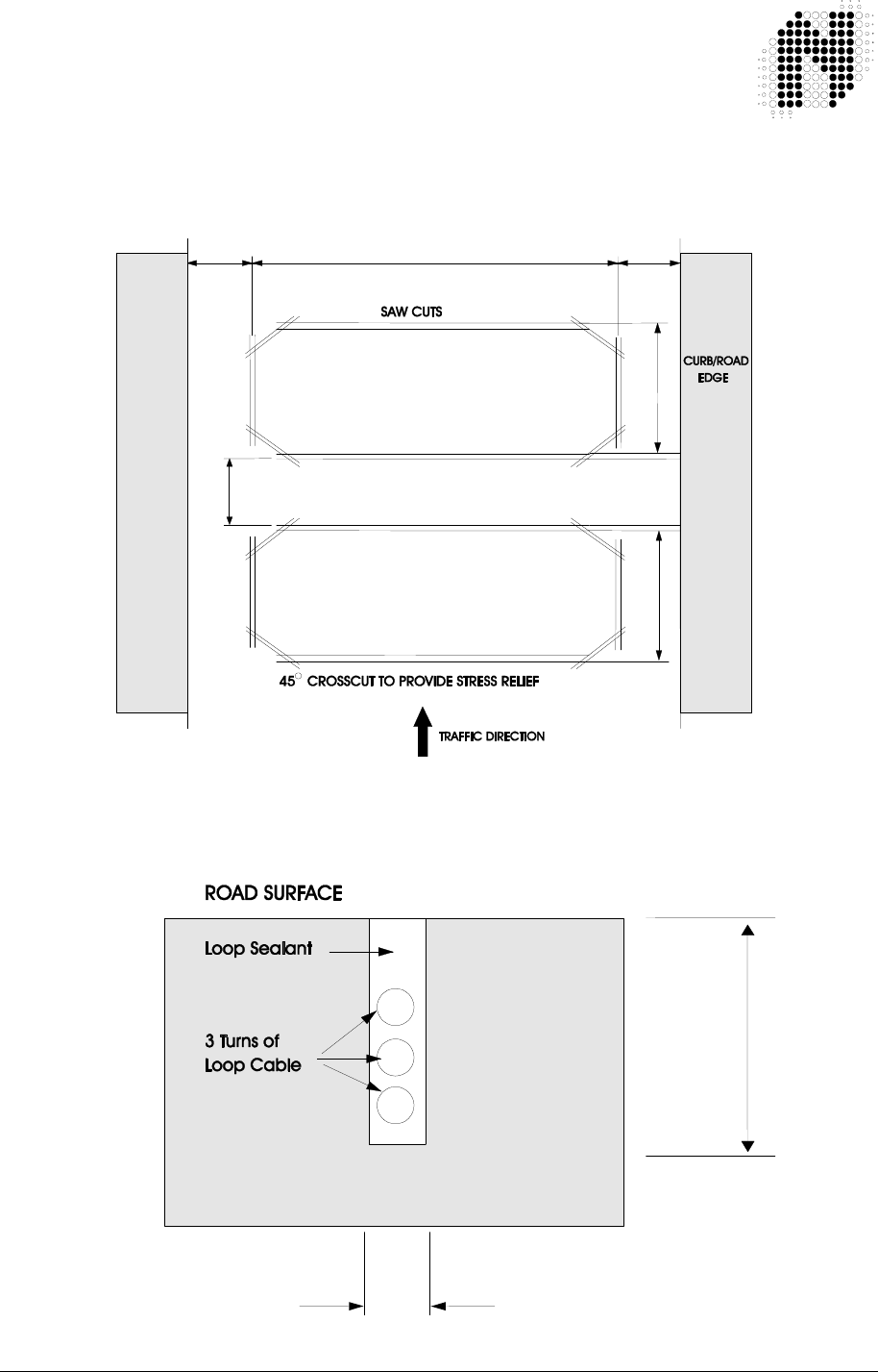
302UM0017 Rev 01 PD230 Enhanced Detector User Manual Page 23 of 37
recommended feeder length is 100 metres. It should be noted that the loop
sensitivity decreases as the feeder length increases, so ideally the feeder cable
should be kept as short as possible.
The loops are sealed using a “quick-set” black epoxy compound or hot bitumen mastic to blend with
the roadway surface.
300 mm 300 mm
+/- 2 m depending on road width
1 m1 m
Min Distance Apart - 2 m (Road width = 2 m)
- 3 m (Road width = 4 m)
Max Distance Apart – No Limit
Figure 5.1 Adjacent loops connected to different detector modules
4 mm
30 – 50 mm

302UM0017 Rev 01 PD230 Enhanced Detector User Manual Page 24 of 37
Figure 5.2 Slot details

302UM0017 Rev 01 PD230 Enhanced Detector User Manual Page 25 of 37
6. CONFIGURATION
WARNING: 8. The connector PIN
assignments vary from model to model.
Refer to the label on the side of the
unit for connector PIN assignment.
NOTE 1: The tables below show the PIN assignments for Nortech’s standard PD230 Enhanced detector
models, on other models the pin assignments may change.
WARNING: 9. The wiring harness is only rated for
SELV voltages (less than 60 V dc or
less than 42 V ac).
If the relays are to switch higher
voltages use CE LVD approved 11 pin
sockets.
NOTE 2: All relay contact descriptions refer to the tuned and undetected state.
6.1 PD231
Enhanced
Detector : English
11 – PIN CONNECTOR WIRING for: 302FT0014
302FT0041
WIRING HARNESS
WIRE COLOUR
11 PIN
Connector
Pin No.
Function
Red 1 Live
Black 2 Neutral 120 V AC ± 10%
30 mA 60 Hz
Blue 3 Channel 1 Loop
Blue 4 Channel 1 Loop Twist this
Pair
Yellow 5 Channel 2 Loop
Yellow 6 Channel 2 Loop Twist this
Pair
Grey 7 Channel 2 N/O Relay Contact
Grey 8 Channel 2 Relay Common Contact
Green/Yellow 9 Earth
White 10 Channel 1 N/O Relay Contact
White 11 Channel 1 Relay Common Contact

302UM0017 Rev 01 PD230 Enhanced Detector User Manual Page 26 of 37
6.2 PD232
Enhanced
Detector: English
11 – PIN CONNECTOR WIRING for: 302FT0026
302FT0041
WIRING HARNESS
WIRE COLOUR
11 PIN
Connector
Pin No.
Function
Red 1 Live
Black 2 Neutral 230 V AC ± 10%
20 mA 50 Hz
Blue 3 Channel 1 Loop
Blue 4 Channel 1 Loop Twist this
pair
Yellow 5 Channel 2 Loop
Yellow 6 Channel 2 Loop Twist this
pair
Grey 7 Channel 2 N/O Relay Contact
Grey 8 Channel 2 Relay Common Contact
Green/Yellow 9 Earth
White 10 Channel 1 N/O Relay Contact
White 11 Channel 1 Relay Common Contact
6.3 PD234
Enhanced
Detector: English
11 – PIN CONNECTOR WIRING for: 302FT0008
302FT0041
WIRING HARNESS
WIRE COLOUR
Pin No. Function
Red 1
Black 2 12 – 24V AC/DC ± 10%
45 – 65 Hz 200 mA max
Blue 3 Channel 1 Loop
Blue 4 Channel 1 Loop Twist this
pair
Yellow 5 Channel 2 Loop
Yellow 6 Channel 2 Loop Twist this
pair
Grey 7 Channel 2 N/O Relay Contact
Grey 8 Channel 2 Relay Common Contact
Green/Yellow 9 Earth
White 10 Channel 1 N/O Relay Contact
White 11 Channel 1 Relay Common Contact
WARNING: 10. The wiring harness wire colour to
PIN No. assignment only applies to
the stated wiring harness Part No.
Other wiring harnesses will have
different wire colour to PIN No.
assignments.

302UM0017 Rev 01 PD230 Enhanced Detector User Manual Page 27 of 37
7. APPLICATIONS
The PD230 Enhanced dual channel detectors can be used in a variety of
applications in the parking and door/gate environments.
• To arm card readers and ticket dispensers
• As a barrier/gate/door closing detector
• As a barrier/gate/door opening detector ( Free exit )
• To generate pulses for vehicle counting
• As a logic unit to determine the direction of traffic flow
Some of the features that make the PD230 Enhanced detectors ideal for these purposes have been
described in the preceding paragraphs.
For more details on parking applications refer to ”Parking Applications Manual”, Document No.
MKT0003.

302UM0017 Rev 01 PD230 Enhanced Detector User Manual Page 28 of 37
8. CUSTOMER FAULT ANALYSIS
8.1 Fault Finding
FAULT
CAUSED BY
REMEDY
Red LED does not glow on
power up
If the indicator is off then there
is a fault on the power
connection to the unit.
Check power feed to the
unit.
After the initial tune period the
Ch1 and/or Ch2 indicator is
green. Turning off for half
second periods.
Unit cannot tune to the loop
due to faulty loop or feeder
connection.
Loop may be too small or too
large.
Faulty detector unit.
Check loop installation
and connections.
Recut as per installation
instructions.
Replace unit.
After tuning, the loop output
LED’s flashes intermittently
and the relay chatters
The loop is getting spurious
detects due to:
a) Crosstalk with
adjacent detector.
b) Faulty loop or feeder
connection.
a) Change frequency
setting.
b) Check that the
feeders are correctly
connected and
adequately twisted.

302UM0017 Rev 01 PD230 Enhanced Detector User Manual Page 29 of 37
8.2 DU100 – Detector Diagnostic Unit
The DU100 Diagnostic unit is a hand-held test instrument that has been designed to
operate with the PD230 Enhanced detector to provide installation/service personnel
with positive verification of the correct operation of the vehicle detector and its installation.
The following parameters may be verified using this instrument:
1. Detector type and version
2. Loop status Display of loop frequency and magnitude of current change
of loop inductance %∆L/L.
3. Frequency Readout of the actual loop operating frequency and the
magnitude of the frequency drift since the last re-tune.
4. Sensitivity Displays the Minimum and Maximum changes of Inductance
%∆L/L that caused a detect since the last re-tune.
5. Status Displays the current status of the detector i.e. Undetect,
Detect, Open circuit, Short circuit or Indeterminate.
6. Time The time in days and hours since the last re-tune and the
reason for the last re-tune i.e. Reset: manual or power failure, Loop
short circuit, Loop open circuit, Indeterminate or an Inductance
change of greater than 15 % ∆ L/L (typical).
This historical information is invaluable in providing information
about intermittent faults.
7. Crosstalk Allows for the comparison of the operating frequencies of
Detector loops in close proximity to each other. If the operating
frequencies are to close the DU100 test will indicate a failure.
For further information refer to the Diagnostic Unit DU100 User Manual Document No. 895UM0001.
It is highly recommended that after installation of a detector (or if the loop has been changed in any
way) that the DU100 Diagnostics Unit is used to verify the correct operation of the detector. A record
of the readings should be kept so that if there is a problem in the future a comparison can be made
to identify what has changed. The form in Appendix C could be used to record these readings.
8.2.1 Interpretation of the DU 100 readings
8.2.1.1 Frequency
For the PD230 Enhanced Detector the Minimum frequency is 24 kHz and the Maximum
frequency is 78 kHz
If a 20 µH loop is connected directly (no feeder cable) to the Detector and the Frequency
switches are set to “High Frequency” the typical frequency would be 78 kHz
If a 1000 µH loop is connected directly (no feeder cable) to the Detector and the Frequency
switches are set to “Low Frequency” the typical frequency would be 24 kHz
If the Frequency reading from the DU100 is close to the Minimum Frequency the inductance of
the LOOP is too large – you need to remove turns from the loop
If the Frequency reading from the DU100 is close to the Maximum Frequency the inductance of
the LOOP is too low and you need to add turns to the loop

302UM0017 Rev 01 PD230 Enhanced Detector User Manual Page 30 of 37
If the detector is operating close to either limit it is possible that either the
frequency drift caused by environmental changes or the shift in frequency
caused by a large ∆L/L detect will cause the frequency to go outside the limits
and cause a retune.
8.2.1.2 Frequency drift
The PD230 Enhanced Detector can handle environmental conditions that can cause the
frequency to drift up to at a rate of approximating 1% ∆L/L per minute.
If the Drift reading approaches this value the detector will have problems tracking the
environmental change
If the drift is higher than say 0.5 % ∆ L/L per minute this will indicate a possible fault with the
loop or feeder cable. Possibly the wire insulation has deteriorated and moisture is causing a
short to earth or that wires of the loop are no longer encapsulated and are moving.
For more information about Frequency drift refer to the “Theory of Application” section in
Diagnostic Unit DU100 User Manual Document No. 895UM0001
8.2.1.3 Sensitivity
For a standard loop of 1.0 metres by 2.0 metres with 2 turns (circumference less than 10
meters) and a ten meter feeder cable the following table shows typical sensitivity values
for different vehicle types
VEHICLE TYPE %∆
∆∆
∆ L/L
Metal Supermarket Trolley
Bicycle 0.04
Motorbike 0.12
Articulated Truck 0.38
SUV (Four Wheel Drive) 0.40
5 Ton Tip Truck 0.45
Motor Car > 1.00
Forklift > 1.00
For more information about Sensitivity refer to the “Theory of Application” section in Diagnostic
Unit DU100 User Manual Document No. 895UM0001
8.2.1.4 Time
This is a powerful tool in identifying problems with an installation. The time since the last retune
of the detector will let you know when the event occurred and the reason will inform you of what
caused the event
8.2.1.5 Crosstalk
For information about resolving crosstalk refer to the “Theory of Application” section in
Diagnostic Unit DU100 User Manual Document No. 895UM0001

302UM0017 Rev 01 PD230 Enhanced Detector User Manual Page 31 of 37
8.3 Functional Test
To test a detector, connect it to an inductive loop with a total inductance in the order
of 300 microhenries. (This may be achieved in the workshop by winding (x) turns of
wire on a non-metal former of diameter (y)).
x = 19 turns 0.25 mm wire
y = 238 mm (9.4 inches)
Bring a small metal object approximately the size of a matchbox close to the loop coil. The following
will happen on detection:
The OUTPUT LED will light up.
The PRESENCE output relay will operate
The PULSE relay will operate momentarily (approximately 150 ms duration)
To check the sensitivity, presence time etc., use should be made of a calibrated tester, which
comprises of a calibrated loop similar to the one described above with a moveable vane, which can
be moved over the loop at pre-determined heights.
This device together with the DU100 hand-held test instrument will allow comprehensive analysis of
the operating characteristics of the detector.

302UM0017 Rev 01 PD230 Enhanced Detector User Manual Page 32 of 37
APPENDIX A - FCC ADVISORY STATEMENT
NOTE: This equipment has been tested and found to comply with the limits of Part 15 of the
FCC Rules. These limits are designed to provide reasonable protection against harmful
interference in a residential installation.
Operation is subject to the following two conditions:
1 This device may not cause harmful interference, and
2 This device must accept any interference received, including interference that may cause
undesired operation
This equipment generates, uses and can radiate radio frequency energy and, if not installed and used in
accordance with the instructions, may cause harmful interference to radio communications.
However, there is no guarantee that interference will not occur in a particular installation. If this equipment
does cause harmful interference to radio or television reception, which can be determined by turning the
equipment off and on, the user is encouraged to try to correct the interference by one or more of the
following measures:
Reorient or relocate the receiving antenna.
Increase the separation between the equipment and receiver.
Connect the equipment into an outlet on a circuit different from that to which the receiver is
connected.
Consult the dealer or an experienced radio/TV technician for help.
The following booklets prepared by the Federal Communications Commission (FCC) may also prove helpful:
• How to Identify and Resolve Radio-TV Interference Problems (Stock No. 004-000-000345-4)
• Interface Handbook (Stock No. 004-000-004505-7)
These booklets may be purchased from the Superintendent of Documents, U.S. Government Printing Office,
Washington, DC 20402.
WARNING: 10. Changes or modifications not expressly approved
by the party responsible for compliance could void
the user’s authority to operate the equipment.

302UM0017 Rev 01 PD230 Enhanced Detector User Manual Page 33 of 37
APPENDIX B – INSTALLATION OUTDOORS
Appendix B.1 IEC 60950-22:2005 – Outdoor cabinet
If the PD230 Enhanced Detector is to be installed outdoors it must be installed in a
cabinet / housing that complies with the requirements of IEC 60950-22:2005 for a
minimum of pollution degree 2.
Appendix B.2 IEC 60950-22:2005 - Northern Europe
To achieve outdoor operation down to -50 °C as requ ired by IEC 60950-22:2005 for
Northern Europe (Finland, Norway and Sweden) a heater with a thermostat must be
included in the cabinet that houses the PD230 Enhanced Detector.
Appendix B.3 IEC 60950-1:2005 – Overvoltage Category
If the unit is likely to be exposed to transient overvoltage greater that IEC 60950-1
Overvoltage Category II additional protection must be provided external to the unit
on the supply lines.

302UM0017 Rev 01 PD230 Enhanced Detector User Manual Page 34 of 37
APPENDIX C - REQUEST FOR TECHNICAL SUPPORT FORM
For Technical support please fill in the form below and send it to your supplier. It is
recommended that at installation you complete this form as a record of the Installation. If
there is a problem later on you can identify what has changed.
For locating faults in “Nortech Inductive Loop Vehicle Detector” installations it is highly recommended
that you use the DU100 DIAGNOSTICS UNIT. Please refer to the DU100 user manual Doc. No.
895UM0001 for details of how to operate the DU100.
Contact Details:- Your Name: ____________________________________________
Your company: ___________________________________________________________________
Telephone No. _______________________ Mobile/Cellphone No. _________________________
FAX No. ____________________________ Email Address
_______________________________
Postal address: ____________________________________
_____________________________________
_____________________________________
Product Model (i.e. PD234) ________________________ Product FT No. 302FT_____________
Product Serial Number: ___________________________
Site Name: _____________________________________ Detector No.
(at the site)
: ______________
What are the settings of the switches on the front of the unit ON or OFF
Switch 1 ___________ (FREQ Frequency)
Switch 2 ___________ (FREQ Frequency)
Switch 3 ___________ (SENS Sensitivity Channel 2)
Switch 4 ___________ (SENS Sensitivity Channel 2)
Switch 5 ___________ (SENS Sensitivity Channel 1 )
Switch 6 ___________ (SENS Sensitivity Channel 1)
Switch 7 ___________ (ASB Automatic Sensitivity Boost)
Switch 8 ___________ (PRES Presence Limited or Permanent)
Switch 9 ___________ (PULSE/PRES Pulse or Presence Channel 2)
Switch 10 ___________ (PULSE/PRES Pulse or Presence Channel 1)
What is the position of the internal link:(Pin 1 to 2 OR Pin 2 to 3 OR Open)? ____________________
(refer to section 3.3 above for functions of this link)
What application is this unit used in (short description)______________________________________
_________________________________________________________________________________
_________________________________________________________________________________

302UM0017 Rev 01 PD230 Enhanced Detector User Manual Page 35 of 37
POWER SUPPLY DETAILS:
Nominal Voltage: _______ V Minimum Voltage: _______ V Maximum Voltage:
________ V
AC or DC ? ______________ If AC then the Frequency _______ Hz
LOOP DETAILS
Channel 1 Channel 2
Size of loop: ____ m by ____ m Size of loop: ____ m by ____ m
Shape of loop: _____________________ Shape of loop: _____________________
Number of Turns: _____ Number of Turns: _____
Size of wire used (mm
2
or AWG) _____________ Size of wire used (mm
2
or AWG) _____________
Type of wire insulation _____________________ Type of wire insulation _____________________
Thickness of insulation:_____________ mm Thickness of insulation:____________ mm
How far below the surface is the loop: ________ mm How far below the surface is the loop: _______ mm
Are there any metal objects below the loops such as concrete reinforcing, water pipes etc if yes please give
details:
_____________________________________________________________________________
____________________________________________________________________________
_____________________________________________________________________________
Are there any power cables below these loops
(Yes/No)
____ If yes please give details:
_____________________________________________________________________________
_____________________________________________________________________________
_____________________________________________________________________________
Are there any other loops in the area
(Yes/No)
____ If so how many? ________ and
how close to these loops are they? ________ m
FEEDER CABLE DETAILS
Channel 1 Channel 2
Length of feeder cable ________ m Length of feeder cable ________ m
Size of wire used (mm
2
or AWG) _____________ Size of wire used (mm
2
or AWG) _____________
(should be 1.5 mm
2
or larger)
Type of wire insulation _____________________ Type of wire insulation _____________________
Thickness of insulation:_____________ mm Thickness of insulation:____________ mm
Type of feeder cable used (screened, armoured, multicore, etc.)
__________________________________________________________________________

302UM0017 Rev 01 PD230 Enhanced Detector User Manual Page 36 of 37
_________________________________________________________________________
________
In the feeder cable how many twists per meter are there?____________ (should be more than 20 per metre)
Are there any other cables close to these feeder cables? (Yes/No) _____ If yes please give details:
_________________________________________________________________________________
___________________________________________________________________
FEEDER CABLE and LOOP DETAILS
Channel 1 Channel 2
Is the loop and feeder cable one continuous Is the loop and feeder cable one continuous
piece of wire or is there a joint between the piece of wire or is there a joint between the
loops and the feeder?
(Yes/No)
_______ loops and the feeder?
(Yes/No)
_______
Please give details:__________________________________________________________________
_________________________________________________________________________________
With the detector disconnected, measure the following:-
Channel 1 Channel 2
AC voltage between the two wires of the AC voltage between the two wires of the
feeder cable __________ V feeder cable __________ V
AC voltage between one of the feeder cable AC voltage between one of the feeder cable
wires and earth __________ V wires and earth __________ V
DC resistance of Feeder plus Loop: _______ ohms DC resistance of Feeder plus Loop: _______ ohms
Inductance of Feeder plus Loop: ________ µH Inductance of Feeder plus Loop: ______ µH
Frequency of measurement? ______ KHz Frequency of measurement? ______ KHz
Loop and feeder resistance to earth Loop and feeder resistance to earth
(with detector unplugged) using a (with detector unplugged) using a
500V Megger: _________ Mega Ohms 500V Megger: _________ Mega Ohms
(should be greater than 10 Mega Ohms)
(should be greater than 10 Mega Ohms)

302UM0017 Rev 01 PD230 Enhanced Detector User Manual Page 37 of 37
READINGS FROM DU100 DIAGNOSTICS UNIT
On arrival at site Time since last retune: ___________ days _____________ hours
Reason for Retune
(Reset: manual or power failure, Short circuit, Open circuit, Indeterminate, Inductance change of greater than
15 % ∆ L/L (typical)
:
_______________________________________________
Channel 1 Channel 2
Frequency ______________ kHz Frequency ______________ kHz
Loop Frequency Drift __________ % Loop Frequency Drift __________ %
Sensitivity Min: ___________ %∆L/L Sensitivity Min: ___________ %∆L/L
Sensitivity Max: ___________ %∆L/L Sensitivity Max: ___________ %∆L/L
Channel Status:____________________________ Channel Status:____________________________
(Undetect, Detect, Open circuit, Short circuit or Indeterminate) (Undetect, Detect, Open circuit, Short circuit or Indeterminate)
Inductance Change for each vehicle type
(Use the maximum sensitivity reading from the DU100 and reset the detector
between each reading)
:
Vehicle Type Channel 1 Inductance Change Channel 2 Inductance Change
Bicycle %∆L/L
%∆L/L
Motorbike %∆L/L
%∆L/L
Car %∆L/L
%∆L/L
SUV %∆L/L
%∆L/L
Articulated truck %∆L/L
%∆L/L
5 Ton Tip Truck %∆L/L
%∆L/L
Forklift %∆L/L
%∆L/L
Other type
(Please specify)
%∆L/L
%∆L/L
Channel 1 Channel 2
Crosstalk
(Pass / Fail)
: _______________ Crosstalk
(Pass / Fail)
: _______________
(If fail actual frequencies of the two problem detector loops) (If fail actual frequencies of the two problem detector loops)
Frequency 1:___________kHz Frequency 1:___________kHz
Frequency 2:______________kHz Frequency 2:______________kHz
Comments: _______________________________________________________________________
______________________________________________________________________________________
______________________________________________________________________________________

Nortech International (Pty) Ltd
PO Box 4099 32A Wiganthorpe Road
Willowton Hub Pietermaritzburg
Pietermaritzburg 3201 South Africa
3200 South Africa Reg. No. 98/1095
Tel: (033) 345 3456 Int. Tel: +27 33 345 3456
Fax: (033) 394 6449 Int Fax: +27 33 394 6449
E-mail: mkt@nortech.co.za URL: www.nortech.co.za
TD236 Enhanced
Vehicle Detector
USER MANUAL
NORTECH INTERNATIONAL (PTY) LTD
All rights reserved.
Copyright © 2009
Document No.: 306UM0002_01a
Date of issue: August 2010
This document is for information only and unless otherwise indicated it is not to form part of any contract.
In accordance with the manufacturer’s policy of continually updating and improving design, specifications contained
herein are subject to alterations without notice.

306UM0002 - 01 TD236 Enhanced Detector User Manual Page 2 of 35
Table of Contents
1. INTRODUCTION .............................................................................................................................5
2. TECHNICAL DATA .........................................................................................................................6
2.1 Functional Data..........................................................................................................................6
2.2 Electrical Data............................................................................................................................6
2.3 Environmental Data....................................................................................................................7
2.4 Mechanical Data ........................................................................................................................8
2.5 Approvals ...................................................................................................................................8
3. OPERATING INSTRUCTIONS .......................................................................................................9
3.1 Hardware Set-up........................................................................................................................9
3.2 Switch Setting Selections...........................................................................................................9
3.2.1 Frequency Switch..............................................................................................................9
3.2.2 Sensitivity ..........................................................................................................................9
3.2.3 Presence Time ................................................................................................................10
3.2.4 Pulse / Presence .............................................................................................................10
3.2.5 Reset Switch ...................................................................................................................10
3.3 Internal Link Selection..............................................................................................................11
3.4 Front Panel Indicators..............................................................................................................11
4. PRINCIPLE OF OPERATION .......................................................................................................12
4.1 Detector Tuning........................................................................................................................12
4.2 Detector Sensitivity ..................................................................................................................12
4.3 Modes of Operation .................................................................................................................13
4.3.1 Presence Mode ...............................................................................................................13
4.3.2 Pulse Mode......................................................................................................................13
4.3.3 AB Logic Presence Mode (Barrier Operation) ................................................................14
4.3.4 AB Logic Pulse Mode (Counting Logic) ..........................................................................16
4.4 Response Times ......................................................................................................................18
5. INSTALLATION GUIDE................................................................................................................19
5.1 Product Safety Requirements..................................................................................................19
5.2 Operational Constraints ...........................................................................................................19
5.2.1 Environmental Factors to Consider.................................................................................19
5.2.2 Crosstalk..........................................................................................................................20
5.2.3 Reinforcing ......................................................................................................................20
5.3 Loop and Feeder Material Specification ..................................................................................20
5.4 Sensing Loop Geometry ..........................................................................................................21
5.5 Loop Installation.......................................................................................................................21
6. CONFIGURATION.........................................................................................................................23
6.1 TD234 Enhanced Detector: English ........................................................................................23
6.2 TD236 Enhanced Detector: English ........................................................................................24
6.3 TD236 Enhanced Detector: .....................................................................................................24
6.4 TD236 Enhanced Detector: .....................................................................................................24
7. APPLICATIONS ............................................................................................................................25
8. CUSTOMER FAULT ANALYSIS ..................................................................................................26
8.1 Fault Finding ............................................................................................................................26
8.2 DU100 – Detector Diagnostic Unit...........................................................................................27
8.2.1 Interpretation of the DU 100 readings.............................................................................27
8.2.1.1 Frequency.........................................................................................................................27
8.2.1.2 Frequency drift.................................................................................................................28
8.2.1.3 Sensitivity.........................................................................................................................28
8.2.1.4 Time .................................................................................................................................28
8.2.1.5 Crosstalk..........................................................................................................................28
8.3 Functional Test.........................................................................................................................29
APPENDIX A - FCC ADVISORY STATEMENT ..................................................................................30
APPENDIX B – INSTALLATION OUTDOORS....................................................................................31
Appendix B.1 IEC 60950-22:2005 – Outdoor cabinet ..............................................................31

306UM0002 - 01 TD236 Enhanced Detector User Manual Page 3 of 35
Appendix B.2 IEC 60950-22:2005 - Northern Europe ..............................................................31
Appendix B.3 IEC 60950-1:2005 – Overvoltage Category.......................................................31
APPENDIX C - REQUEST FOR TECHNICAL SUPPORT FORM.......................................................32

306UM0002 - 01 TD236 Enhanced Detector User Manual Page 4 of 35
WARNING: 1. THIS UNIT MUST BE
EARTHED !
WARNING: 2. DISCONNECT POWER BEFORE
WORKING ON THIS UNIT !
WARNING: 3. INSTALLATION AND OPERATION
BY SERVICE PERSONNEL ONLY !
WARNING: 4. NO USER SERVICEABLE PARTS INSIDE.
ONLY SERVICE PERSONNEL MAY OPEN THE
UNIT TO CHANGE INTERNAL SETTINGS!
WARNING: 5. USA
FCC Advisory Statement – Refer to Appendix A at
the end of this document.
WARNING: 6.
Europe
Disposing of the product.
This electronic product is subject to the
EU Directive 2002/96/EC for Waste
Electrical and Electronic Equipment
(WEEE). As such, this product must not
be disposed of at a local municipal
waste collection point. Please refer to
local regulations for directions on how
to dispose of this product in an
environmental friendly manner.
306UM0002 - 01 TD236 Enhanced Detector User Manual Page 5 of 35
1. INTRODUCTION
The “TD236 Enhanced Two Channel Inductive Loop Vehicle Detector” is a dual
channel microprocessor based detector designed specifically for traffic control applications. The
TD236 Enhanced detector has been designed using the latest technology in order to meet the
requirements of a vast number of traffic applications in terms of operating conditions. A number of
internal functional options are available to the user.
The primary function of the detector is to detect vehicle presence by means of an inductance
change caused by the vehicle passing over a wire loop buried under the road surface.
The detector has been designed for ease of installation and convenience. The various modes are
selected by changing the position of switches on the front of the unit.
The detector oscillator is multiplexed to eliminate any possibility of crosstalk between the loops
connected to the detector.
The switches allow for different loop frequency settings, sensitivity settings and mode settings.
The unit has a number of internally selectable options for configuration of the relay outputs.
The TD236 Enhanced detector provides visual outputs (LED) on the front of the enclosure and relay
change-over contacts at the 11 pin connector at the rear of the enclosure. The power LED indicates
that the unit has been powered. The channel status LED’s below indicate that a vehicle is present
over the loop and when there is a fault on the loop. The Presence relays are normally fail-safe and
will close on a vehicle detect, loop failure or in the event of a power failure.
For additional information refer to the following documents:
Data Sheet - TD236 Enhanced 2 Ch Vehicle Detector Document No. 306DS0001
Installation Leaflet Document No. 879LF0006
Diagnostic Unit DU100 User Manual Document No.
895UM0001
2/4 Ch Vehicle Detector Installation Guide Document No. 879LF0006

306UM0002 - 01 TD236 Enhanced Detector User Manual Page 6 of 35
2. TECHNICAL DATA
2.1 Functional Data
Tuning Fully automatic
Self-tuning range 20 to 1000 µH
Sensitivity Four step switch selectable:
High 0.02% ∆ L/L
Medium-High 0.05% ∆ L/L
Medium-Low 0.10% ∆ L/L
Low 0.50% ∆ L/L
Frequency Four step selectable:
Frequency dependent on loop size
Modes Output relays may operate in the Presence ( fail-safe ),
or Direction logic modes
Presence Time Switch selectable:
1 Second
4 Minutes
40 Minutes
No fixed time-out (dependant on inductance change) Approx.
1 hour for 3 % ∆ L/L
Response Times 75 milliseconds
Drift Compensation Rate Approx. 1% ∆ L/L per minute
Visual Indication 1 x Power LED - Red
2 x Channel Status LED - Green
Relay Outputs 2 x Relays, User Configurable as Presence or Pulse outputs,
Normally Open (N/O) contacts
(Opto-Isolated Outputs are available on request. MOQ applies)
Reset Reset by push button on front of enclosure
Surge Protection Loop isolation transformer, gas discharge tubes,
and Zener diode clamping on loop input
2.2 Electrical Data
Power requirements 230V AC ± 10% 48 to 62Hz
230V models: 1.5 VA Maximum at 230V
12V - 10% to 24V + 10% DC/AC 48 to 62Hz
12-24 V models: 1 VA Maximum at 12V
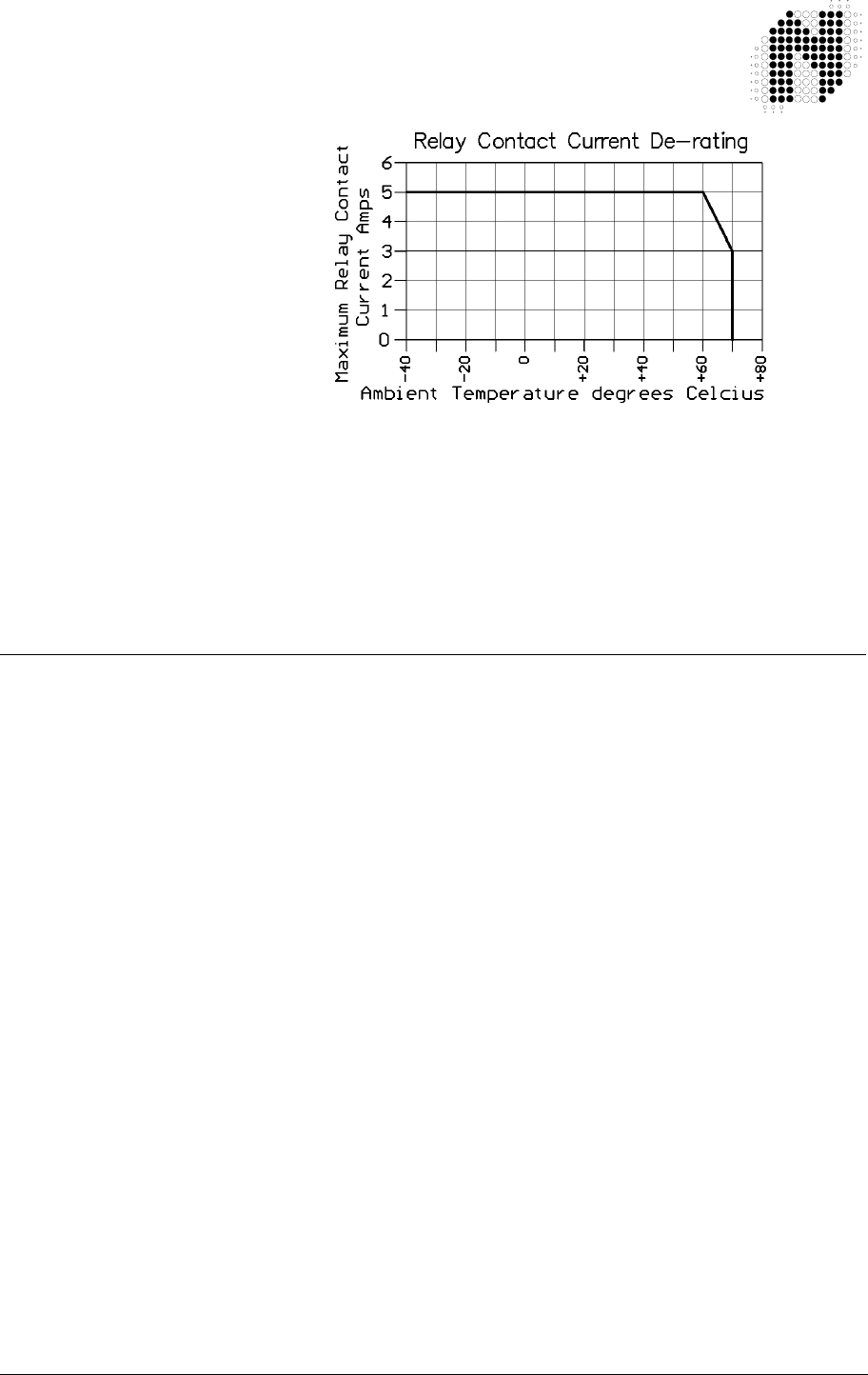
306UM0002 - 01 TD236 Enhanced Detector User Manual Page 7 of 35
Relay Contact Rating 2 x Relays rated - 5A @ 230 VAC
For ambient temperatures above 60 °C De-rate the
relay maximum current as per graph below
Opto-Isolated Output rating 33 V 50 mA
Note - Opto-Isolated Outputs are available on request. MOQ
applies
2.3 Environmental Data
Storage Temperature -40°C to +85°C
Operating Temperature -40°C to +70°C
Humidity Up to 95% relative humidity without condensation
Circuit Protection Conformal coating over the PCB and all components
IP Rating IP 30. - This product MUST be installed in an enclosure
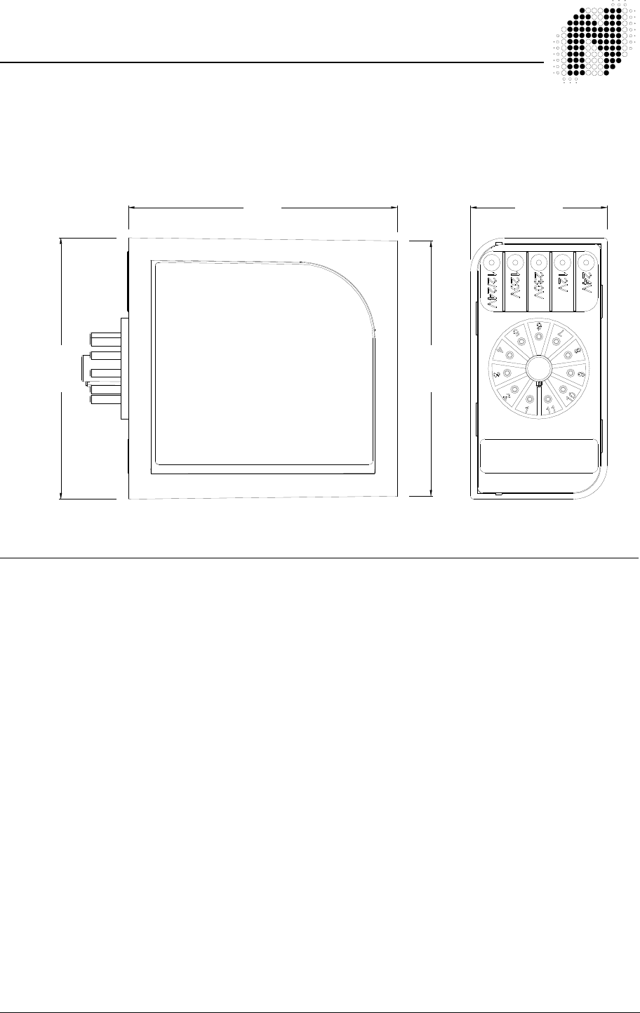
306UM0002 - 01 TD236 Enhanced Detector User Manual Page 8 of 35
2.4 Mechanical Data
Housing material ABS blend
Mounting Position Shelf or DIN rail mounting
Connections 11-pin submagnal type ( JEDEC No. B11– 88 )
Size of Housing 78mm ( High ) x 41mm ( Wide ) x 80mm ( Deep )
2.5 Approvals
C.E. Regulations EN 301 489 Equipment Type: III
Class of Equipment: 2
EN 50293 Performance Criteria B
Safety: IEC / EN 60950-1
80 mm
75.9 mm
77.7 mm
40.6 mm
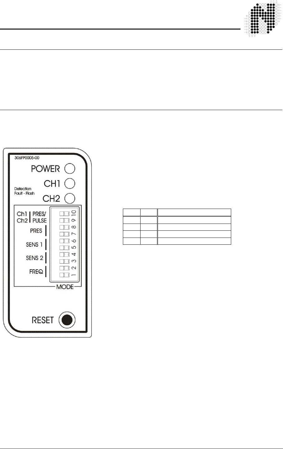
306UM0002 - 01 TD236 Enhanced Detector User Manual Page 9 of 35
3. OPERATING INSTRUCTIONS
3.1 Hardware Set-up
The TD236 Enhanced dual channel traffic detector is designed to be shelf or DIN rail mounted with
the controls and visual indicators at the front and wiring at the rear of the enclosure.
The power, loop and relay outputs are all connected to the single 11-pin plug, which is mounted at
the rear of the enclosure.
3.2 Switch Setting Selections
3.2.1 Frequency Switch
Where more than one detector is used at the same site, the
detectors must be set-up to ensure that there is no CROSSTALK
(interference) between adjacent loops connected to different
detectors.
For more information about crosstalk refer to section 5.2.2.
The frequency switches are the lower two switches, numbered 1
and 2. There are four frequency selections and are set as follows:
The frequency switches allow the operating frequencies of the
detector to be shifted higher or lower depending on the setting of the
two switches.
The operating frequency of the detector channel is determined by:
Inductance of the loop and feeder cable
Detector frequency switch settings
The operating frequency of the detector channel increases as the
loop inductance decreases and vice versa.
The inductance of the loop and feeder cable is determined by:
Size of the loop
Number of turns in the loop
Length of feeder cable
As a general rule, the detector connected to the inductive loop with the greatest inductance should
be set to operate at the lowest frequency.
When the frequency switch setting is altered, the operating frequency of both detector channels will
shift. Because the unit has a common oscillator and the multiplexer connects the loops alternatively
to this oscillator.
3.2.2 Sensitivity
The sensitivity of the detector allows the detector to be selective as to the magnitude of the change
of inductance necessary to produce an output. There are four sensitivity selections and are set as
follows: -
S1 S2 Frequency Setting
Off Off High frequency
Off On Medium-High frequency
On Off Medium-Low frequency
On On Low frequency

306UM0002 - 01 TD236 Enhanced Detector User Manual Page 10 of 35
Channel1 Channel 2
S6 S5 S4 S3
Off Off Off Off High
On Off On Off Medium-High
Off On Off On Medium-Low
On On On On Low
3.2.3 Presence Time
The presence time is a mode, which allows the detector to have a presence time of no longer than
the time set by the switch settings. There are four presence time selections available and can be
selected by using switches numbered 7 and 8 on the front of the enclosure as follows: -
S8 S7
Off Off ∞ no fixed time
On Off 40 minutes
Off On 4 minutes
On On 1 Second
The presence time as shown above, may be altered according to the requirements.
The 1 second presence time setting will give a pulse on detection of a vehicle with a duration of 1
second. The detector will immediately re-adjust to the normal operating point and will give another
detect in the event of a further change in the loop inductance. The detector may be used as a
passage detector in this mode.
The 4 minute and 40 minute presence time settings work in the same way as the 1 second setting,
however the detector will now give outputs of 4 minutes or 40 minutes. If the vehicle which caused
the inductance change moves off the loop within the selected time period, then the detector will go
out of detect and the presence time will be reset to zero for the next detect cycle. The detector may
undetect before the expired time period if the change in inductance for the vehicle is small
The “no fixed time-out” setting does not have a fixed time period and the presence time is
dependant on the magnitude of the inductance change caused by the vehicle over the loop.
On times longer than 1 second there will be a “paralysis time” of approximately 4 seconds between
actuations.
3.2.4 Pulse / Presence
The channel’s relay may be set to either Pulse Mode or Presence Mode with switches No. 9 & No.
10 as shown in the table below: -
Channel1 Channel 2
S10 S9
Off Off Presence
On On Pulse
3.2.5 Reset Switch
The detector automatically tunes to the inductive loops connected to it when power is applied,
whether on initial installation or after any interruption in the power supply. Should it be necessary to
retune the detector, as may be required after the changing of any switch selections or after moving
the detector from one installation to another, momentary operation of the RESET switch will initiate
the automatic tuning cycle. Tuning should take approximately 5 seconds
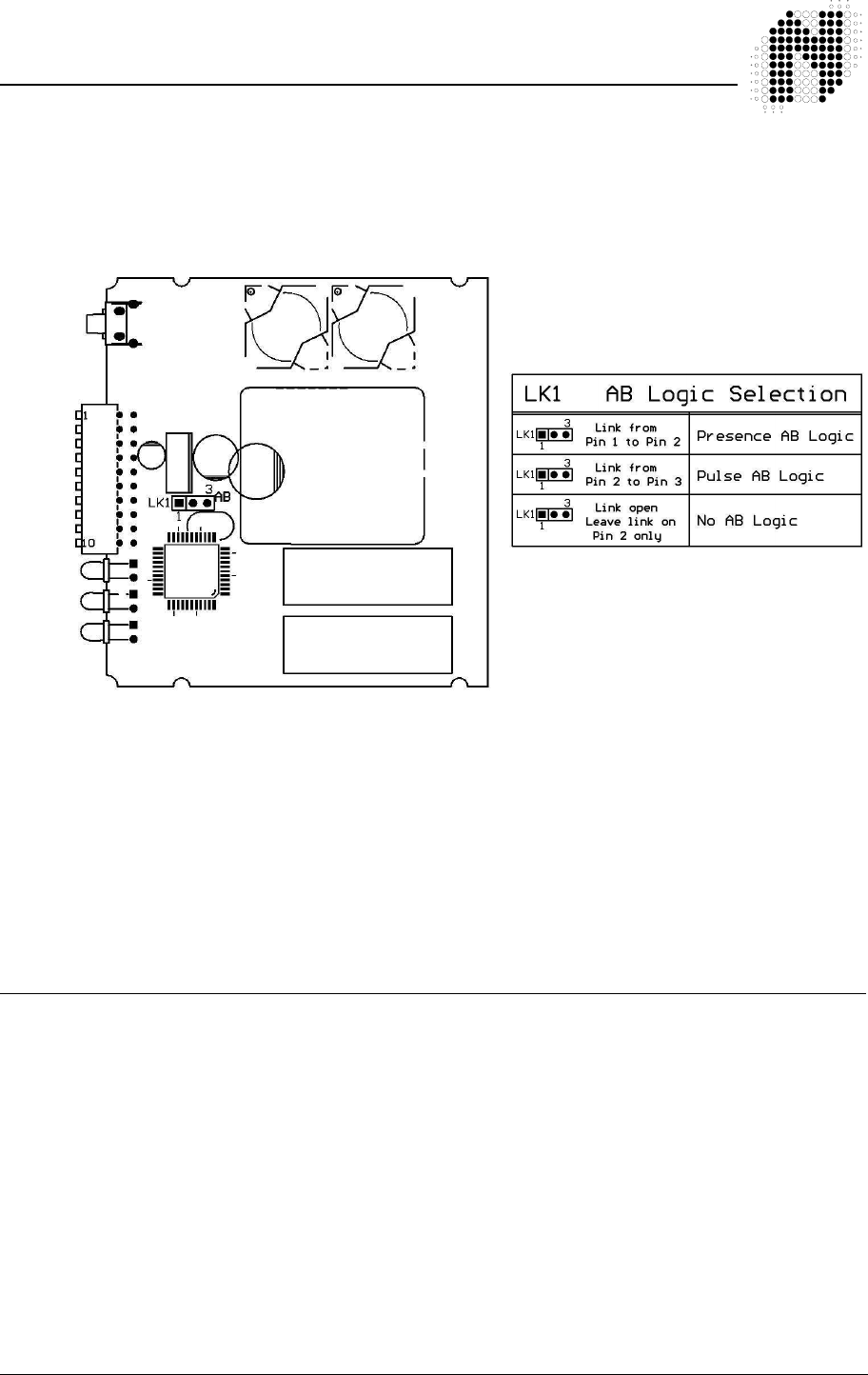
306UM0002 - 01 TD236 Enhanced Detector User Manual Page 11 of 35
3.3 Internal Link Selection
WARNING - ONLY SERVICE PERSONNEL MAY OPEN THE UNIT
TO CHANGE INTERNAL SETTINGS!
There is one 3 way link located inside the TD236 Enhanced detector housing, which is used to alter
the mode of operation of the detector. The link has been placed inside the unit to avoid incorrect
operation due to selection by an unauthorised operator.
For a description of the AB Logic mode refer to section 4.3 “Modes of Operation” below
For the TD236 Enhanced traffic detector, the default setting for both channel output relays is
presence mode (Front panel switches 9 & 10 OFF) with no AB logic (i.e. no jumper on LK1).
It is recommended that for traffic applications, both channel output relays remain in presence mode
(i.e. front panel switches 9 & 10 ON). Should the AB-logic mode be required, it is recommended that
presence AB logic mode is selected (i.e. a jumper on link LK1 from pin 1 to pin 2 as shown in the
above diagram).
3.4 Front Panel Indicators
While the detector is tuning, the Channel LED will indicate the “mode” status of the detector.
i) Any Channel output operating in the presence or pulse modes will come on and extinguish when
the system is tuned.
ii) When the AB Logic mode is selected, the Channel LED’s will alternatively flash slow and
extinguish when the system is tuned.
If a loop fault exists the Channel LED will come on and flash indicating a fault. If the fault is self-
healing the detector will continue to operate and the LED will continue to show the historical fault.
The detector must be reset or power removed to clear the historical fault information.
The channel LED will also glow whenever a vehicle is detected passing over the inductive loop.
The Power LED at the top of the unit will remain on to indicate that the unit is powered. This LED is
also used as the link to the diagnostic unit ( DU100 ).

306UM0002 - 01 TD236 Enhanced Detector User Manual Page 12 of 35
4. PRINCIPLE OF OPERATION
The inductive loop vehicle detector senses the presence of a vehicle over an area
defined by a loop of two or more turns of wire laid under the road or pavement surface. This loop of
wire is connected to the detector by a pair of wires called a loop feeder.
A vehicle passing over a sensing loop causes a small reduction in the inductance of the loop, which
is sensed by the detector. The sensitivity of detection is adjustable to accommodate a wide range of
vehicle types as well as different loop and feeder combinations.
Upon detection of a vehicle passing over the loop the detector operates its output relays which may
be used to indicate controls associated with the installation.
4.1 Detector Tuning
Tuning of the detector is fully automatic. The detector will re-tune if any of the following events
occur:- - When power is applied to the detector.
- A detector reset is initiated via the reset button.
- A detect of greater than 15% ∆ L/L occurs.
The detector will automatically tune each channel to its connected loop. The detector will tune to any
loop in the inductance range of 20 to 1000 micro-henries.
This wide range ensures that all loop sizes and feeder combinations will be accommodated in the
tuning range of the detector.
Once tuned, any slow environmental change in loop inductance is fed to a compensating circuit
within the detector, which keeps the detector correctly tuned.
4.2 Detector Sensitivity
Sensitivity of the detection system is dependent on factors such as loop size, number of turns in the
loop, feeder length and the presence of metal reinforcing beneath the loop.
The nature of the application determines the required sensitivity level, which may be adjusted by
means of the sensitivity switches on the front panel.
Sensitivity levels on the TD236 Enhanced detectors have been carefully optimised for traffic control
applications.
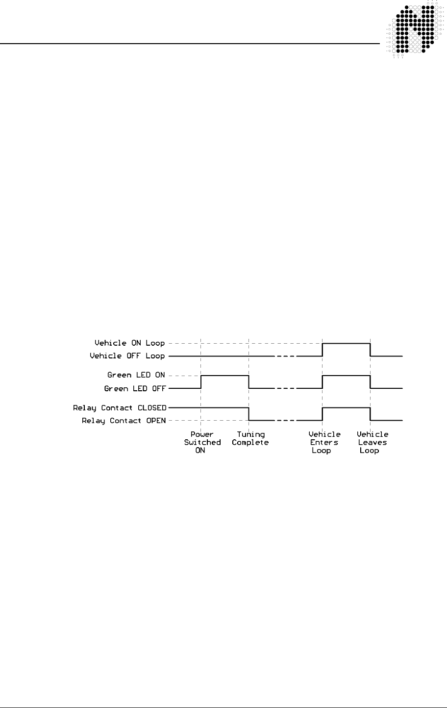
306UM0002 - 01 TD236 Enhanced Detector User Manual Page 13 of 35
4.3 Modes of Operation
The TD236 Enhanced Detector may be configured for any one of the following
modes:
Presence Mode
Pulse Mode
AB Logic Presence Mode (Barrier Operation)
AB Logic Pulse Mode (Counting Logic)
4.3.1 Presence Mode
Link LK1 open
To set Channel 1 to Presence mode switch OFF switch 10
To set Channel 2 to Presence mode switch OFF switch 9
In the presence mode the detector channels operate independently
In the presence mode the detector will give a continuous output during the presence of a
vehicle over the inductive loop, providing that the preset time has not expired. Upon expiry,
the detector will undetect and tune out the vehicle over the loop. Refer to section 3.2.3
above for presence time settings.
If the no fixed time-out presence time setting is selected, then the detect time will be
dependent on the change of inductance.
The presence outputs are known as fail-safe outputs. This implies that in the event of a
power failure or loop failure the detector will give detect outputs. (Fail-Secure Presence
Mode is available on request. MOQ applies)
4.3.2 Pulse Mode
Link LK1 open
To set Channel 1 to Pulse mode switch ON switch 10
To set Channel 2 to Pulse mode switch ON switch 9
In the pulse mode the detector channels operate independently.
In the pulse mode the detector will give a pulse of 150 millisecond duration, when a vehicle
enters the loop (Pulse on Detect) (a pulse of 250 millisecond is available on request. MOQ
applies).
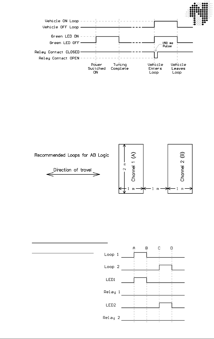
306UM0002 - 01 TD236 Enhanced Detector User Manual Page 14 of 35
(Pulse on un-detect is available on request. MOQ applies)
4.3.3 AB Logic Presence Mode (Barrier Operation)
Internal link LK1 shorted from Pin 1 to Pin 2. In this mode switches 9 & 10 are ignored.
AB LOGIC Presence Mode is a direction logic mode, and is capable of determining direction
of travel of a vehicle. Two loops are laid in the direction of travel to provide the input for this
mode.
If a vehicle enters Channel 1 Loop and then proceeds to Channel 2 Loop, Channel 1 relay
contacts will close for the duration of that the vehicle is over Channel 2 Loop.
If a vehicle enters Channel 2 Loop and then proceeds to Channel 1 Loop, Channel 2 relay
contacts will close for the duration of that the vehicle is over Channel 1 Loop.
Progress of a vehicle over the loops
Case 1:
(AB LOGIC Presence Mode)
Forward direction
A - Vehicle Enters Loop1
B - Vehicle Exits Loop 1,
C - Vehicle Enters Loop2,
D - Vehicle Exits Loop 2,
Typically caused by loops
being too far apart or very
small vehicles
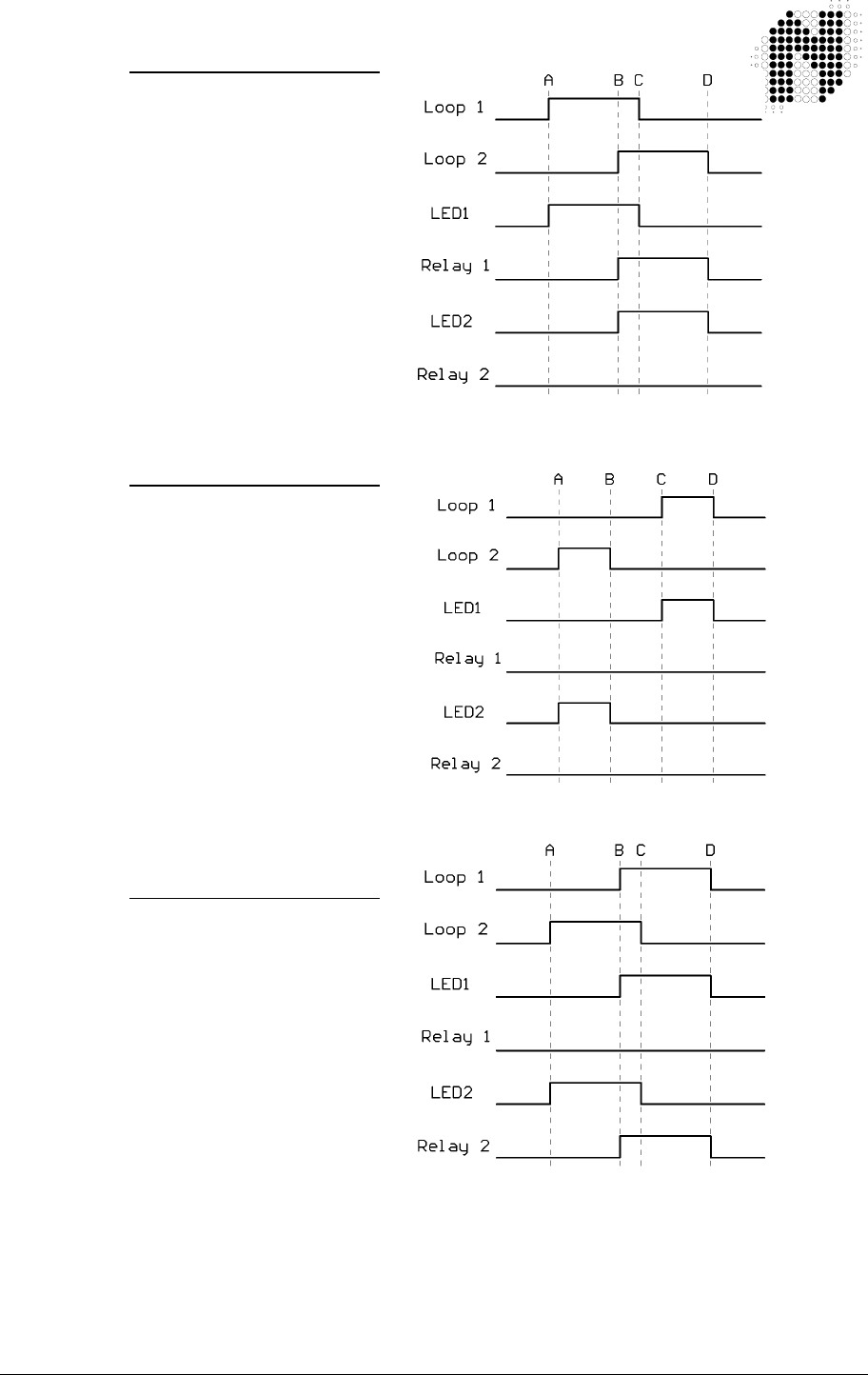
306UM0002 - 01 TD236 Enhanced Detector User Manual Page 15 of 35
Case 2:
(AB LOGIC Presence Mode)
Forward direction
A - Vehicle Enters Loop1
B - Vehicle Enters Loop2
C - Vehicle Exits Loop 1
D - Vehicle Exits Loop 2
This is the correct forward
operation for Presence
AB Logic
Case 3:
(AB LOGIC Presence Mode)
Reverse direction
A - Vehicle Enters Loop2
B - Vehicle Exits Loop 2
C - Vehicle Enters Loop1
D - Vehicle Exits Loop 1
Typically caused by loops
being too far apart or very
small vehicles
Case 4:
(AB LOGIC Presence Mode)
Reverse direction
A - Vehicle Enters Loop2
B - Vehicle Enters Loop1
C - Vehicle Exits Loop 2
D - Vehicle Exits Loop 1
This is the correct reverse
operation for Presence
AB Logic
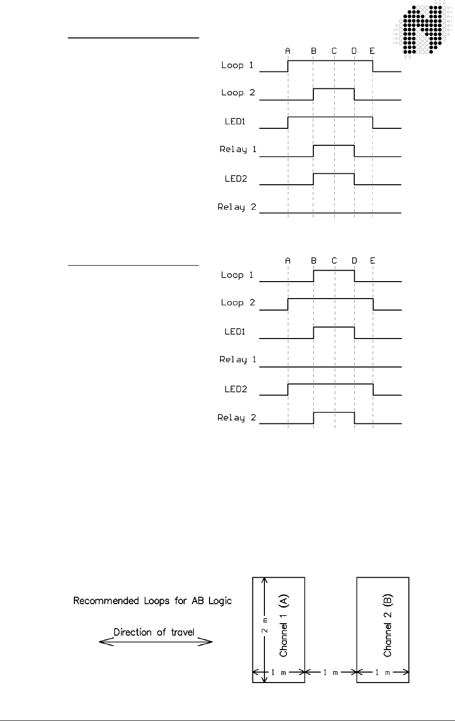
306UM0002 - 01 TD236 Enhanced Detector User Manual Page 16 of 35
Case 5:
(AB LOGIC Presence Mode)
Forward direction
A - Vehicle Enters Loop1
B - Vehicle Enters Loop2
C - Vehicle Starts to reverse
D - Vehicle Exits Loop 2
E - Vehicle Exits Loop 1
This case should not
happen but it does
occasionally
Case 6:
(AB LOGIC Presence Mode)
Reverse direction
A - Vehicle Enters Loop2
B - Vehicle Enters Loop1
C - Vehicle Starts to reverse
D - Vehicle Exits Loop 1
E - Vehicle Exits Loop 2
This case should not
happen but it does
occasionally
4.3.4 AB Logic Pulse Mode (Counting Logic)
Internal link LK1 shorted from Pin 2 to Pin 3. In this mode switches 9 & 10 are ignored.
AB LOGIC Pulse Mode is a direction logic mode, and is capable of determining direction of
travel of a vehicle. Two loops are laid in the direction of travel to provide the input for this
mode.
This mode is used to activate equipment requiring vehicle direction inputs such as automatic
fee collection equipment, vehicle counters, or warning devices in one-way systems.
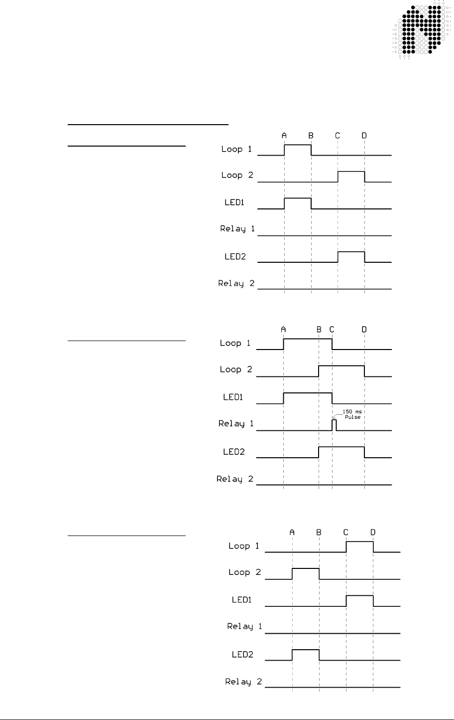
306UM0002 - 01 TD236 Enhanced Detector User Manual Page 17 of 35
If a vehicle enters Channel 1 Loop and then proceeds to Channel 2 Loop, a
150 ms pulse will be issued on Channel 1 relay output as the vehicle leaves
Channel 1 Loop.
If a vehicle now enters Channel 2 Loop and then proceeds to Channel 1 Loop, a 150 ms
pulse will be issued on Channel 2 relay output as the vehicle leaves Channel 2 Loop.
Progress of a vehicle over the loops
Case 1:
(AB LOGIC Pulse Mode)
Forward direction
A - Vehicle Enters Loop1
B - Vehicle Exits Loop 1,
C - Vehicle Enters Loop2,
D - Vehicle Exits Loop 2,
Typically caused by loops
being too far apart or very
small vehicles
Case 2:
(AB LOGIC Pulse Mode)
Forward direction
A - Vehicle Enters Loop1
B - Vehicle Enters Loop2
C - Vehicle Exits Loop 1
D - Vehicle Exits Loop 2
This is the correct forward
operation for Pulse
AB Logic
Case 3:
(AB LOGIC Pulse Mode)
Reverse direction
A - Vehicle Enters Loop2
B - Vehicle Exits Loop 2
C - Vehicle Enters Loop1
D - Vehicle Exits Loop 1
Typically caused by loops
being too far apart or very
small vehicles

306UM0002 - 01 TD236 Enhanced Detector User Manual Page 18 of 35
Case 4:
(AB LOGIC Pulse Mode)
Reverse direction
A - Vehicle Enters Loop2
B - Vehicle Enters Loop1
C - Vehicle Exits Loop 2
D - Vehicle Exits Loop 1
This is the correct reverse
operation for Pulse
AB Logic
Case 5:
(AB LOGIC Pulse Mode)
Forward direction
A - Vehicle Enters Loop1
B - Vehicle Enters Loop2
C - Vehicle Starts to reverse
D - Vehicle Exits Loop 2
E - Vehicle Exits Loop 1
This case should not
happen but it does
occasionally
Case 6:
(AB LOGIC Pulse Mode)
Reverse direction
A - Vehicle Enters Loop2
B - Vehicle Enters Loop1
C - Vehicle Starts to reverse
D - Vehicle Exits Loop 1
E - Vehicle Exits Loop 2
This case should not
happen but it does
occasionally
4.4 Response Times
The response time of the detector is the time taken from when a vehicle moves over the loop to
when the detector gives an output on that channel.
The response times of the TD236 Enhanced detectors have been adjusted to provide adequate
response to vehicles in traffic control applications.

306UM0002 - 01 TD236 Enhanced Detector User Manual Page 19 of 35
5. INSTALLATION GUIDE
Optimum functioning of the detector module is largely dependent on factors
associated with the inductive sensor loop connected to it. These factors include choice of material,
loop configuration and correct installation practice. A successful inductive loop vehicle detection
system can be achieved by bearing the following constraints in mind, and strictly following the
installation instructions. The detector must be installed in a convenient weatherproof location as
close as possible to the loop.
5.1 Product Safety Requirements
• i) WARNING: The unit must be EARTHED.
• ii) WARNING: Disconnect the power before working on the unit.
• iii) WARNING: On 120 Vac and 230 Vac models, a readily accessible disconnect
device must be incorporated into the mains wiring (as per EN60950-1:2005
Section 1.7.2.2).
• iv) WARNING: All models the power supply to the unit MUST have short circuit
protection and over current protection installed at the power supply source
(As per EN 60950-1:2005 section 1.7.2.3) typically this will be a 5 Amp
Magnetic Circuit Breaker for AC models and a fuse for DC models.
• v) WARNING: This product must be installed in an enclosure as the IP rating of the
detector is IP30.
• vi) WARNING: No user serviceable parts inside.
ONLY SERVICE PERSONNEL MAY OPEN THE UNIT TO CHANGE
INTERNAL SETTINGS
• vii) WARNING: Only use CE approved 11 pin relay bases such as Nortech Part No.
CTR119090 or equivalent.
As an alternative to the 11 pin relay base, Nortech has a 11 pin wiring
harness, Nortech Part No. 302FT0041, which can only be used in SELV
voltage (less than 60 V dc or less than 42 V ac) applications.
5.2 Operational Constraints
5.2.1 Environmental Factors to Consider
Even though the TD236 Enhanced traffic detectors are housed, the system integrator MUST ensure
that the detector is installed in a housing/fire enclosure to protect it from the environment.
The TD236 Enhanced traffic detectors are rated to operate from – 40°C to +70°C but the rate of
temperature change MUST not exceed 1°C per minute. The system integrator MUST ensure that
the housing used complies with this rate of temperature change requirement.
For installation Outdoors refer to Appendix B
For additional information on Environmental Factors refer to the section “Environmental Influences
to Design Parameters” in the “Loops and Loop Installations” Manual, Nortech Document No.
MKT05.

306UM0002 - 01 TD236 Enhanced Detector User Manual Page 20 of 35
5.2.2 Crosstalk
When two or more loop configurations are in close proximity, the magnetic fields of
one loop can overlap and disturb the field of another loop. This phenomena, is known as crosstalk, it
can cause false detects and detector lock-up.
Should the loops be connected to the same dual channel detector crosstalk will not occur, due to the
fact that sequential polling of the loops takes place, resulting in only one loop being energised at a
given time.
Crosstalk between adjacent loops operating from different detector modules can be eliminated by:
1. Careful choice of operating frequency. The closer together the two loops, the further apart
the frequencies of operation must be.
2. Separation between adjacent loops. Where possible a minimum spacing of 2 metres
between loops should be adhered to.
3. Careful screening of feeder cables if they are routed together with other electrical cables.
The screen must be earthed at the detector end only.
4. Running feeder cables in their own slots, separated by at least 300 mm.
For additional information on Crosstalk refer to the section “Crosstalk Prevention” in the DU100
Diagnostic Unit User Manual Nortech Document No. 895UM0001
5.2.3 Reinforcing
The existence of reinforced steel below the road surface has the effect of reducing the inductance,
and therefore the sensitivity, of the loop detection system. Hence, where reinforcing exists 2 turns
should be added to the normal loop, as referred to in section 5.3.
The ideal minimum spacing between the loop and the cable and steel reinforcing is 150 mm,
although this is not always practically possible. The slot depth should be kept as shallow as
possible, taking care that no part of the loop or the feeder remains exposed after the sealing
compound has been applied.
5.3 Loop and Feeder Material Specification
Extensive studies have been undertaken over the years by various agencies around the world in
order to ascertain the optimum loop installation materials.
As an insulated conductor is a prerequisite, PVC covered cable has been used for many years as a
first choice, but tests have shown, in fact, that this is unsuitable for long term installations. The PVC
tends to become porous with the result that adjacent loops become electrically coupled to one
another, with resultant crosstalk implications. Instability and susceptibility to electrical interference
can also result.
The insulation must withstand wear and abrasion from the shifting streets, moisture, and attack by
solvents and oils, as well as withstand the heat of high temperature sealants.
Silicone insulated cable has emerged as one of the preferred insulation materials. Other insulation
materials are rubber, thermoplastic, synthetic polymer and cross linked polyethylene.
Stranded loop wire is preferred over solid wire. Because of its mechanical characteristics, a
stranded wire is more likely to survive bending and stretching than a solid.
A heavy gauge conductor is definitely desirous in order to maintain the loop Q-factor. The loop and
feeder should preferably constitute a single length of insulated multi-stranded copper conductor,
with no joints and with the copper having a minimum cross section 1.5 mm
2
. The feeder is twisted to
minimise the effect of electrical noise.

306UM0002 - 01 TD236 Enhanced Detector User Manual Page 21 of 35
Joints in the loop or feeder are not recommended. Where this is not possible, joints
are to be soldered and terminated in a waterproof junction box. This is extremely
important for reliable detector performance. Other forms of joins such as those available in kits,
where the joint is properly sealed against moisture, are also permitted.
5.4 Sensing Loop Geometry
NOTE: 1) The circumference of the loop must not exceed 30 m.
2) The area of the loop must not exceed 30 m
2
and must not be less than 1 m
2
.
3) The loop must be constructed as detailed below.
Sensing loops should, unless site conditions prohibit, be rectangular in shape and should normally
be installed with the longest sides at right angles to the direction of traffic movement. These sides
should ideally be 1 metre apart.
Loops operating from the same detector module can share a common slot along one of the longer
sides, if so required. This type of configuration could be applied in a direction logic application. The
maximum separation permitted for this application is 1 metre, ensuring that a vehicle can straddle
both loops simultaneously in the required direction of travel.
The only factor which governs maximum separation between loops in all other applications is the
feeder length, with 100 metres being the maximum recommended length.
The length of the loop will be determined by the width of the roadway to be monitored. The loop
should reach to within 300 mm of each edge of the roadway.
In general, loops having a circumference measurement in excess of 10 metres should be installed
using two turns of wire, while loops of less than 10 metres in circumference should have three turns
or more. Loops having a circumference measurement less than 7 metres should have four turns.
It is good practice at time of installation to construct adjacent loops with alternate three and four turn
windings.
For additional Information on loop geometry refer to the following documents:
• “INDUCTIVE LOOP VEHICLE DETECTION” - Nortech Doc. No. MKT01.
• “TRAFFIC DETECTION” - Nortech Doc. No. MKT02.
• “PARKING APPLICATIONS MANUAL” - Nortech Doc. No. MKT03.
• “LOOPS and LOOP INSTALLATION” – Nortech Doc. No. MKT05
5.5 Loop Installation
All permanent loop installations should be installed in the roadway by cutting slots with a masonry
cutting disc or similar device. A 45° crosscut shou ld be made across the loop corners to reduce the
chance of damage that can be caused to the loop at right angle corners.
NOMINAL SLOT WIDTH: 4 mm
NOMINAL SLOT DEPTH: 30 mm to 50 mm
A slot must also be cut from the loop circumference at one corner of the loop to the roadway edge to
accommodate the feeder.
A continuous loop and feeder is obtained by leaving a tail long enough to reach the detector before
inserting the cable into the loop slot. Once the required number of turns of wire are wound into the
slot around the loop circumference, the wire is routed again via the feeder slot to the roadway edge.
A similar length is allowed to reach the detector and these two free ends are twisted together to
ensure they remain in close proximity to one another. (Minimum 20 turns per metre). Maximum
recommended feeder length is 100 metres. It should be noted that the loop sensitivity decreases as
the feeder length increases, so ideally the feeder cable should be kept as short as possible.
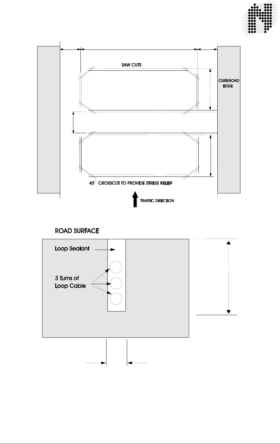
306UM0002 - 01 TD236 Enhanced Detector User Manual Page 22 of 35
The loops are sealed using a “quick-set” black epoxy compound or hot bitumen
mastic to blend with the roadway surface.
300 mm 300 mm
+/- 2 m depending on road width
1 m1 m
Min Distance Apart - 2 m (Road width = 2 m)
- 3 m (Road width = 4 m)
Max Distance Apart – No Limit
Figure 5.1 Adjacent loops connected to different detector modules
4 mm
30 – 50 mm
Figure 5.2 Slot details

306UM0002 - 01 TD236 Enhanced Detector User Manual Page 23 of 35
6. CONFIGURATION
WARNING: 7. The connector PIN assignments
vary from model to model.
Refer to the label on the side of the
unit for connector PIN assignment.
NOTE 1: The tables below show the PIN assignments for Nortech’s standard TD236 Enhanced detector
models, on other models the pin assignments may change.
WARNING: 8. The wiring harness is only rated for
SELV voltages (less than 60 V dc or
less than 42 V ac).
If the relays are to switch higher
voltages use CE LVD approved 11 pin
sockets.
NOTE 2: All relay contact descriptions refer to the tuned and undetected state.
6.1 TD234 Enhanced Detector
: English
11 – PIN CONNECTOR WIRING for: 306FT0002 / 306FT0008
302FT0041
WIRING HARNESS
WIRE COLOUR
11 PIN
Connector
Pin No.
Function
Red 1 Live
Black 2 Neutral 12 – 24V AC/DC ± 10%
45 – 65 Hz 200 mA max
Blue 3 Channel 1 Loop
Blue 4 Channel 1 Loop Twist this
pair
Yellow 5 Channel 2 Loop
Yellow 6 Channel 2 Loop Twist this
pair
Grey 7 Channel 2 N/O Relay Contact or OPTO+
Grey 8 Channel 2 Relay Common Contact or OPTO-
Green/Yellow 9 Earth
White 10 Channel 1 N/O Relay Contact or OPTO+
White 11 Channel 1 Relay Common Contact or OPTO-

306UM0002 - 01 TD236 Enhanced Detector User Manual Page 24 of 35
6.2 TD236 Enhanced Detector
: English
11 – PIN CONNECTOR WIRING for: 306FT0004
302FT0041
WIRING HARNESS
WIRE COLOUR
11 PIN
Connector
Pin No.
Function
Red 1 Live
Black 2 Neutral 230 V AC ± 10%
20 mA 50 Hz
Blue 3 Channel 1 Loop
Blue 4 Channel 1 Loop Twist this
pair
Yellow 5 Channel 2 Loop
Yellow 6 Channel 2 Loop Twist this
pair
Grey 7 Channel 2 N/O Relay Contact or OPTO+
Grey 8 Channel 2 Relay Common Contact or OPTO-
Green/Yellow 9 Earth
White 10 Channel 1 N/O Relay Contact or OPTO+
White 11 Channel 1 Relay Common Contact or OPTO-
6.3 TD236 Enhanced Detector
:
11 – PIN CONNECTOR WIRING
302FT0070
WIRING HARNESS
WIRE COLOUR
11 PIN
Connector
Pin No.
Function
Red 1 Live
Black 2 Neutral 230 V AC ± 10%
20 mA 50 Hz
Grey 3 Channel 2 N/O Relay Contact
Grey 4 Channel 2 Common Contact
White 5 Channel 1 N/O Relay Contact
White 6 Channel 1 Common Contact
Blue 7 Channel 1 Loop
Blue 8 Channel 1 Loop Twist this
Pair
Green/Yellow 9 Earth
Yellow 10 Channel 2 Loop
Yellow 11 Channel 2 Loop Twist this
Pair
6.4 TD236 Enhanced Detector
:
11 – PIN CONNECTOR WIRING
302FT0071
WIRING HARNESS
WIRE COLOUR
11 PIN
Connector
Pin No.
Function
Red 1 Live
Black 2 Neutral 120 V AC ± 10%
30 mA 50 Hz
Grey 3 Channel 2 Relay Common Contact
Green/Yellow 4 Earth
White 5 Channel 1 Relay Common Contact
White 6 Channel 1 N/O Relay Contact
Blue 7 Channel 1 Loop
Blue 8 Channel 1 Loop Twist this
Pair
Yellow 9 Channel 2 Loop
Yellow 10 Channel 2 Loop Twist this
Pair
Grey 11 Channel 2 N/O Relay Contact

306UM0002 - 01 TD236 Enhanced Detector User Manual Page 25 of 35
WARNING: 9. The wiring harness wire
colour to PIN No.
assignment only applies to the
stated wiring harness Part No.
Other wiring harnesses will have
different wire colour to PIN No.
assignments.
7. APPLICATIONS
The TD236 Enhanced dual channel detectors can be used in a variety of applications in the traffic
and vehicle control environments.
For VA (Vehicle Actuated) or SVA (Semi Vehicle Actuated) traffic intersection control.
Some of the features that make the TD236 Enhanced detector ideal for these purposes have been
described in the preceding paragraphs.
For more details on traffic applications refer to ”Traffic Applications Manual”, Document No. MKT04.

306UM0002 - 01 TD236 Enhanced Detector User Manual Page 26 of 35
8. CUSTOMER FAULT ANALYSIS
8.1 Fault Finding
FAULT
CAUSED BY
REMEDY
Red LED does not glow on
power up
If the indicator is off then there
is a fault on the power
connection to the unit.
Check power feed to the
unit.
After the initial tune period the
Ch1 and/or Ch2 indicator is
green. Turning off for half
second periods.
Unit cannot tune to the loop
due to faulty loop or feeder
connection.
Loop may be too small or too
large.
Faulty detector unit.
Check loop installation
and connections.
Recut as per installation
instructions.
Replace unit.
After tuning, the loop output
LED’s flashes intermittently
and the relay chatters
The loop is getting spurious
detects due to:
a) Crosstalk with
adjacent detector.
b) Faulty loop or feeder
connection.
a) Change frequency
setting.
b) Check that the
feeders are correctly
connected and
adequately twisted.

306UM0002 - 01 TD236 Enhanced Detector User Manual Page 27 of 35
8.2 DU100 – Detector Diagnostic Unit
The DU100 Diagnostic unit is a hand-held test instrument that has been designed to
operate with the TD236 Enhanced detector to provide installation/service personnel with positive
verification of the correct operation of the vehicle detector and its installation.
The following parameters may be verified using this instrument:
1. Detector type and version
2. Loop status Display of loop frequency and magnitude of current change
of loop inductance %∆L/L.
3. Frequency Readout of the actual loop operating frequency and the
magnitude of the frequency drift since the last re-tune.
4. Sensitivity Displays the Minimum and Maximum changes of Inductance
%∆L/L that caused a detect since the last re-tune.
5. Status Displays the current status of the detector i.e. Undetect,
Detect, Open circuit, Short circuit or Indeterminate.
6. Time The time in days and hours since the last re-tune and the
reason for the last re-tune i.e. Reset: manual or power failure, Loop
short circuit, Loop open circuit, Indeterminate or an Inductance
change of greater than 15 % ∆ L/L (typical).
This historical information is invaluable in providing information
about intermittent faults.
7. Crosstalk Allows for the comparison of the operating frequencies of
Detector loops in close proximity to each other. If the operating
frequencies are to close the DU100 test will indicate a failure.
For further information refer to the Diagnostic Unit DU100 User Manual Document No. 895UM0001.
It is highly recommended that after installation of a detector (or if the loop has been changed in any
way) that the DU100 Diagnostics Unit is used to verify the correct operation of the detector. A record
of the readings should be kept so that if there is a problem in the future a comparison can be made
to identify what has changed. The form in Appendix C could be used to record these readings.
8.2.1 Interpretation of the DU 100 readings
8.2.1.1 Frequency
For the TD236 Enhanced Detector the Minimum frequency is 24 kHz and the Maximum
frequency is 78 kHz
If a 20 µH loop is connected directly (no feeder cable) to the Detector and the Frequency
switches are set to “High Frequency” the typical frequency would be 78 kHz
If a 1000 µH loop is connected directly (no feeder cable) to the Detector and the Frequency
switches are set to “Low Frequency” the typical frequency would be 24 kHz
If the Frequency reading from the DU100 is close to the Minimum Frequency the inductance of
the LOOP is too large – you need to remove turns from the loop
If the Frequency reading from the DU100 is close to the Maximum Frequency the inductance of
the LOOP is too low and you need to add turns to the loop

306UM0002 - 01 TD236 Enhanced Detector User Manual Page 28 of 35
If the detector is operating close to either limit it is possible that either the
frequency drift caused by environmental changes or the shift in frequency
caused by a large ∆L/L detect will cause the frequency to go outside the limits
and cause a retune.
8.2.1.2 Frequency drift
The TD236 Enhanced Detector can handle environmental conditions that can cause the
frequency to drift up to at a rate of approximating 1% ∆L/L per minute.
If the Drift reading approaches this value the detector will have problems tracking the
environmental change
If the drift is higher than say 0.5 % ∆ L/L per minute this will indicate a possible fault with the
loop or feeder cable. Possibly the wire insulation has deteriorated and moisture is causing a
short to earth or that wires of the loop are no longer encapsulated and are moving.
For more information about Frequency drift refer to the “Theory of Application” section in
Diagnostic Unit DU100 User Manual Document No. 895UM0001
8.2.1.3 Sensitivity
For a standard loop of 1.0 metres by 2.0 metres with 2 turns (circumference less than 10
meters) and a ten meter feeder cable the following table shows typical sensitivity values
for different vehicle types
VEHICLE TYPE %∆
∆∆
∆ L/L
Metal Supermarket Trolley
Bicycle 0.04
Motorbike 0.12
Articulated Truck 0.38
SUV (Four Wheel Drive) 0.40
5 Ton Tip Truck 0.45
Motor Car > 1.00
Forklift > 1.00
For more information about Sensitivity refer to the “Theory of Application” section in Diagnostic
Unit DU100 User Manual Document No. 895UM0001
8.2.1.4 Time
This is a powerful tool in identifying problems with an installation. The time since the last retune
of the detector will let you know when the event occurred and the reason will inform you of what
caused the event
8.2.1.5 Crosstalk
For information about resolving crosstalk refer to the “Theory of Application” section in
Diagnostic Unit DU100 User Manual Document No. 895UM0001

306UM0002 - 01 TD236 Enhanced Detector User Manual Page 29 of 35
8.3 Functional Test
To test a detector, connect it to an inductive loop with a total inductance in the order
of 300 micro-henries. (This may be achieved in the workshop by winding (x) turns of wire on a non-
metal former of diameter (y)).
x = 19 turns 0.25 mm wire
y = 238 mm (9.4 inches)
Bring a small metal object approximately the size of a matchbox close to the loop coil. The following
will happen on detection:
The relevant channel OUTPUT LED will light up.
The relevant channel PRESENCE output relay will operate
To check the sensitivity, presence time etc., use should be made of a calibrated tester, which
comprises of a calibrated loop similar to the one described above with a moveable vane, which can
be moved over the loop at pre-determined heights.
This device together with the DU100 hand-held test instrument will allow comprehensive analysis of
the operating characteristics of the detector.

306UM0002 - 01 TD236 Enhanced Detector User Manual Page 30 of 35
APPENDIX A - FCC ADVISORY STATEMENT
NOTE: This equipment has been tested and found to comply with the limits of Part 15 of the
FCC Rules. These limits are designed to provide reasonable protection against harmful interference in a
residential installation.
Operation is subject to the following two conditions:
1 This device may not cause harmful interference, and
2 This device must accept any interference received, including interference that may cause
undesired operation
This equipment generates, uses and can radiate radio frequency energy and, if not installed and used in
accordance with the instructions, may cause harmful interference to radio communications.
However, there is no guarantee that interference will not occur in a particular installation. If this equipment
does cause harmful interference to radio or television reception, which can be determined by turning the
equipment off and on, the user is encouraged to try to correct the interference by one or more of the
following measures:
Reorient or relocate the receiving antenna.
Increase the separation between the equipment and receiver.
Connect the equipment into an outlet on a circuit different from that to which the receiver is
connected.
Consult the dealer or an experienced radio/TV technician for help.
The following booklets prepared by the Federal Communications Commission (FCC) may also prove helpful:
• How to Identify and Resolve Radio-TV Interference Problems (Stock No. 004-000-000345-4)
• Interface Handbook (Stock No. 004-000-004505-7)
These booklets may be purchased from the Superintendent of Documents, U.S. Government Printing Office,
Washington, DC 20402.
WARNING: 10. Changes or modifications not expressly approved
by the party responsible for compliance could void
the user’s authority to operate the equipment.

306UM0002 - 01 TD236 Enhanced Detector User Manual Page 31 of 35
APPENDIX B – INSTALLATION OUTDOORS
Appendix B.1 IEC 60950-22:2005 – Outdoor cabinet
If the TD236 Enhanced Detector is to be installed outdoors it must be installed in a
cabinet / housing that complies with the requirements of IEC 60950-22:2005 for a
minimum of pollution degree 2.
Appendix B.2 IEC 60950-22:2005 - Northern Europe
To achieve outdoor operation down to -50 °C as requ ired by IEC 60950-22:2005 for
Northern Europe (Finland, Norway and Sweden) a heater with a thermostat must be
included in the cabinet that houses the TD236 Enhanced Detector.
Appendix B.3 IEC 60950-1:2005 – Overvoltage Category
If the unit is likely to be exposed to transient overvoltage greater that IEC 60950-1
Overvoltage Category II additional protection must be provided external to the unit
on the supply lines.

306UM0002 - 01 TD236 Enhanced Detector User Manual Page 32 of 35
APPENDIX C - REQUEST FOR TECHNICAL SUPPORT FORM
For Technical support please fill in the form below and send it to your supplier. It is
recommended that at installation you complete this form as a record of the Installation. If there is a problem
later on you can identify what has changed.
For locating faults in “Nortech Inductive Loop Vehicle Detector” installations it is highly recommended
that you use the DU100 DIAGNOSTICS UNIT. Please refer to the DU100 user manual Doc. No.
895UM0001 for details of how to operate the DU100.
Contact Details:- Your Name: ____________________________________________
Your company: ___________________________________________________________________
Telephone No. _______________________ Mobile/Cellphone No. _________________________
FAX No. ____________________________ Email Address
_______________________________
Postal address: ____________________________________
_____________________________________
_____________________________________
Product Model (i.e. TD236) ________________________ Product FT No. 306FT_____________
Product Serial Number: ___________________________
Site Name: _____________________________________ Detector No.
(at the site)
: ______________
What are the settings of the switches on the front of the unit ON or OFF
Switch 1 ___________ (FREQ Frequency)
Switch 2 ___________ (FREQ Frequency)
Switch 3 ___________ (SENS Sensitivity Channel 2)
Switch 4 ___________ (SENS Sensitivity Channel 2)
Switch 5 ___________ (SENS Sensitivity Channel 1 )
Switch 6 ___________ (SENS Sensitivity Channel 1)
Switch 7 ___________ (ASB Automatic Sensitivity Boost)
Switch 8 ___________ (PRES Presence Limited or Permanent)
Switch 9 ___________ (PULSE/PRES Pulse or Presence Channel 2)
Switch 10 ___________ (PULSE/PRES Pulse or Presence Channel 1)
What is the position of the internal link:(Pin 1 to 2 OR Pin 2 to 3 OR Open)? ____________________
(refer to section 3.3 above for functions of this link)
What application is this unit used in (short description)______________________________________
_________________________________________________________________________________
_________________________________________________________________________________

306UM0002 - 01 TD236 Enhanced Detector User Manual Page 33 of 35
POWER SUPPLY DETAILS:
Nominal Voltage: _______ V Minimum Voltage: _______ V Maximum Voltage:
________ V
AC or DC ? ______________ If AC then the Frequency _______ Hz
LOOP DETAILS
Channel 1 Channel 2
Size of loop: ____ m by ____ m Size of loop: ____ m by ____ m
Shape of loop: _____________________ Shape of loop: _____________________
Number of Turns: _____ Number of Turns: _____
Size of wire used (mm
2
or AWG) _____________ Size of wire used (mm
2
or AWG) _____________
Type of wire insulation _____________________ Type of wire insulation _____________________
Thickness of insulation:_____________ mm Thickness of insulation:____________ mm
How far below the surface is the loop: ________ mm How far below the surface is the loop: _______ mm
Are there any metal objects below the loops such as concrete reinforcing, water pipes etc if yes please give
details:
_____________________________________________________________________________
____________________________________________________________________________
_____________________________________________________________________________
Are there any power cables below these loops
(Yes/No)
____ If yes please give details:
_____________________________________________________________________________
_____________________________________________________________________________
_____________________________________________________________________________
Are there any other loops in the area
(Yes/No)
____ If so how many? ________ and
how close to these loops are they? ________ m
FEEDER CABLE DETAILS
Channel 1 Channel 2
Length of feeder cable ________ m Length of feeder cable ________ m
Size of wire used (mm
2
or AWG) _____________ Size of wire used (mm
2
or AWG) _____________
(should be 1.5 mm
2
or larger)
Type of wire insulation _____________________ Type of wire insulation _____________________
Thickness of insulation:_____________ mm Thickness of insulation:____________ mm
Type of feeder cable used (screened, armoured, multicore, etc.)
__________________________________________________________________________
_________________________________________________________________________________

306UM0002 - 01 TD236 Enhanced Detector User Manual Page 34 of 35
In the feeder cable how many twists per meter are there?____________ (should be more
than 20 per metre)
Are there any other cables close to these feeder cables? (Yes/No) _____ If yes please give details:
_________________________________________________________________________________
___________________________________________________________________
FEEDER CABLE and LOOP DETAILS
Channel 1 Channel 2
Is the loop and feeder cable one continuous Is the loop and feeder cable one continuous
piece of wire or is there a joint between the piece of wire or is there a joint between the
loops and the feeder?
(Yes/No)
_______ loops and the feeder?
(Yes/No)
_______
Please give details:__________________________________________________________________
_________________________________________________________________________________
With the detector disconnected, measure the following:-
Channel 1 Channel 2
AC voltage between the two wires of the AC voltage between the two wires of the
feeder cable __________ V feeder cable __________ V
AC voltage between one of the feeder cable AC voltage between one of the feeder cable
wires and earth __________ V wires and earth __________ V
DC resistance of Feeder plus Loop: _______ ohms DC resistance of Feeder plus Loop: _______ ohms
Inductance of Feeder plus Loop: ________ µH Inductance of Feeder plus Loop: ______ µH
Frequency of measurement? ______ KHz Frequency of measurement? ______ KHz
Loop and feeder resistance to earth Loop and feeder resistance to earth
(with detector unplugged) using a (with detector unplugged) using a
500V Megger: _________ Mega Ohms 500V Megger: _________ Mega Ohms
(should be greater than 10 Mega Ohms)
(should be greater than 10 Mega Ohms)

306UM0002 - 01 TD236 Enhanced Detector User Manual Page 35 of 35
READINGS FROM DU100 DIAGNOSTICS UNIT
On arrival at site Time since last retune: ___________ days _____________ hours
Reason for Retune
(Reset: manual or power failure, Short circuit, Open circuit, Indeterminate, Inductance change of greater than
15 % ∆ L/L (typical)
:
_______________________________________________
Channel 1 Channel 2
Frequency ______________ kHz Frequency ______________ kHz
Loop Frequency Drift __________ % Loop Frequency Drift __________ %
Sensitivity Min: ___________ %∆L/L Sensitivity Min: ___________ %∆L/L
Sensitivity Max: ___________ %∆L/L Sensitivity Max: ___________ %∆L/L
Channel Status:____________________________ Channel Status:____________________________
(Undetect, Detect, Open circuit, Short circuit or Indeterminate) (Undetect, Detect, Open circuit, Short circuit or Indeterminate)
Inductance Change for each vehicle type
(Use the maximum sensitivity reading from the DU100 and reset the detector
between each reading)
:
Vehicle Type Channel 1 Inductance Change Channel 2 Inductance Change
Bicycle %∆L/L
%∆L/L
Motorbike %∆L/L
%∆L/L
Car %∆L/L
%∆L/L
SUV %∆L/L
%∆L/L
Articulated truck %∆L/L
%∆L/L
5 Ton Tip Truck %∆L/L
%∆L/L
Forklift %∆L/L
%∆L/L
Other type
(Please specify)
%∆L/L
%∆L/L
Channel 1 Channel 2
Crosstalk
(Pass / Fail)
: _______________ Crosstalk
(Pass / Fail)
: _______________
(If fail actual frequencies of the two problem detector loops) (If fail actual frequencies of the two problem detector loops)
Frequency 1:___________kHz Frequency 1:___________kHz
Frequency 2:______________kHz Frequency 2:______________kHz
Comments: _______________________________________________________________________
______________________________________________________________________________________
______________________________________________________________________________________