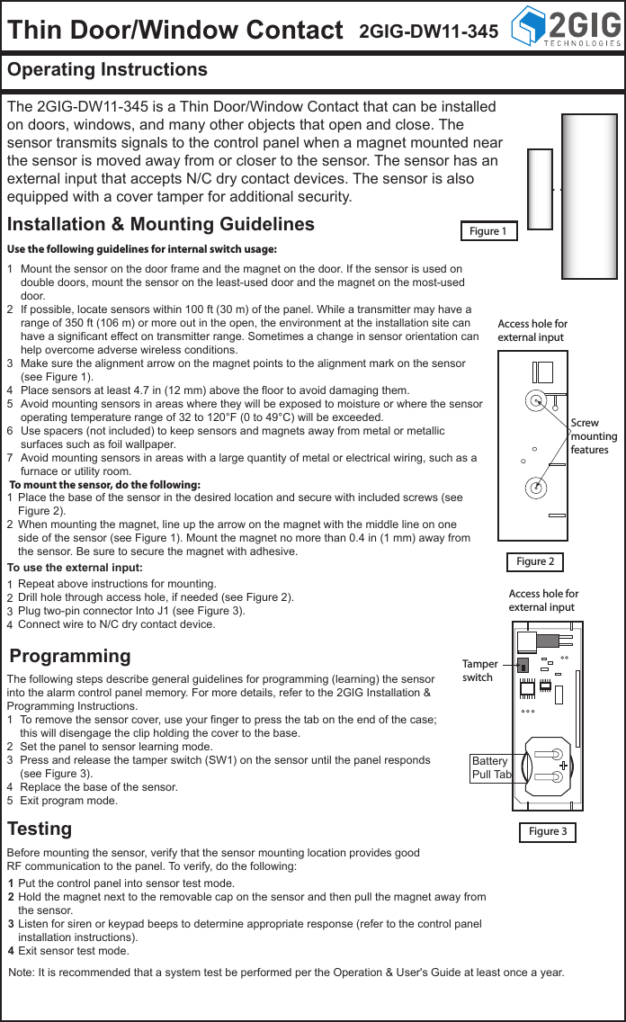
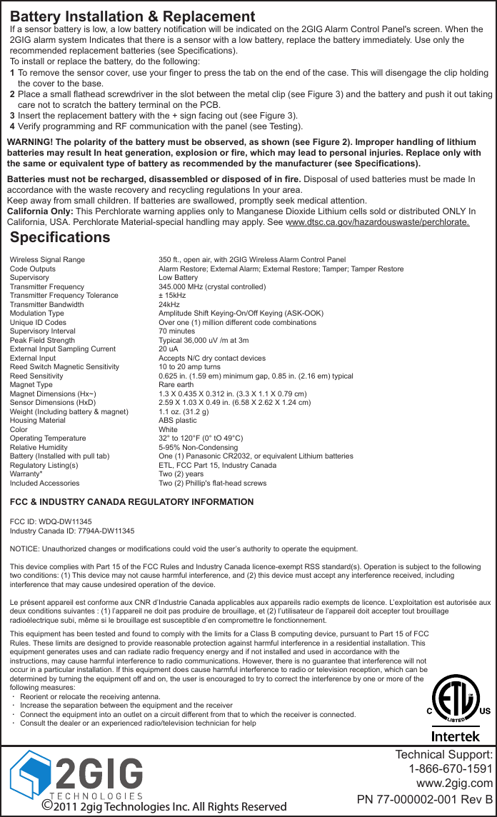
Nortek Security and Control 2GIG DW11345 Recessed Door/Window Contact User Manual DW11 IG 77 000002 001 Rev B

2GIG Technologies, Inc. Recessed Door/Window Contact DW11 IG 77 000002 001 Rev B

User manual

Thin Door/Window Contact 2GIG-DW11-345Operating InstructionsThe 2GIG-DW11-345 is a Thin Door/Window Contact that can be installed on doors, windows, and many other objects that open and close. The sensor transmits signals to the control panel when a magnet mounted near the sensor is moved away from or closer to the sensor. The sensor has an external input that accepts N/C dry contact devices. The sensor is also equipped with a cover tamper for additional security.Installation & Mounting GuidelinesProgrammingTestingFigure 1Use the following guidelines for internal switch usage:Access hole forexternal inputScrewmountingfeaturesAccess hole forexternal inputTamperswitchFigure 2Figure 3To mount the sensor, do the following:To use the external input:Mount the sensor on the door frame and the magnet on the door. If the sensor is used on double doors, mount the sensor on the least-used door and the magnet on the most-used door.If possible, locate sensors within 100 ft (30 m) of the panel. While a transmitter may have a range of 350 ft (106 m) or more out in the open, the environment at the installation site can have a significant effect on transmitter range. Sometimes a change in sensor orientation can help overcome adverse wireless conditions.Make sure the alignment arrow on the magnet points to the alignment mark on the sensor (see Figure 1).Place sensors at least 4.7 in (12 mm) above the floor to avoid damaging them.Avoid mounting sensors in areas where they will be exposed to moisture or where the sensor operating temperature range of 32 to 120°F (0 to 49°C) will be exceeded.Use spacers (not included) to keep sensors and magnets away from metal or metallic surfaces such as foil wallpaper.Avoid mounting sensors in areas with a large quantity of metal or electrical wiring, such as a furnace or utility room.1234567Repeat above instructions for mounting.Drill hole through access hole, if needed (see Figure 2).Plug two-pin connector Into J1 (see Figure 3).Connect wire to N/C dry contact device.1234To remove the sensor cover, use your finger to press the tab on the end of the case; this will disengage the clip holding the cover to the base.Set the panel to sensor learning mode.Press and release the tamper switch (SW1) on the sensor until the panel responds (see Figure 3).Replace the base of the sensor.Exit program mode.12345Put the control panel into sensor test mode.Hold the magnet next to the removable cap on the sensor and then pull the magnet away from the sensor.Listen for siren or keypad beeps to determine appropriate response (refer to the control panel installation instructions).Exit sensor test mode.1234Place the base of the sensor in the desired location and secure with included screws (see Figure 2).When mounting the magnet, line up the arrow on the magnet with the middle line on one side of the sensor (see Figure 1). Mount the magnet no more than 0.4 in (1 mm) away from the sensor. Be sure to secure the magnet with adhesive.12The following steps describe general guidelines for programming (learning) the sensor into the alarm control panel memory. For more details, refer to the 2GIG Installation & Programming Instructions.BatteryPull TabBefore mounting the sensor, verify that the sensor mounting location provides good RF communication to the panel. To verify, do the following:Note: It is recommended that a system test be performed per the Operation & User's Guide at least once a year.
Battery Installation & ReplacementWARNING! The polarity of the battery must be observed, as shown (see Figure 2). Improper handling of lithium batteries may result In heat generation, explosion or fire, which may lead to personal injuries. Replace only with the same or equivalent type of battery as recommended by the manufacturer (see Specifications).Batteries must not be recharged, disassembled or disposed of in fire. Disposal of used batteries must be made In accordance with the waste recovery and recycling regulations In your area.Keep away from small children. If batteries are swallowed, promptly seek medical attention.California Only: This Perchlorate warning applies only to Manganese Dioxide Lithium cells sold or distributed ONLY In California, USA. Perchlorate Material-special handling may apply. See www.dtsc.ca.gov/hazardouswaste/perchlorate.SpecificationsWireless Signal RangeCode OutputsSupervisoryTransmitter FrequencyTransmitter Frequency ToleranceTransmitter BandwidthModulation TypeUnique ID CodesSupervisory IntervalPeak Field StrengthExternal Input Sampling CurrentExternal InputReed Switch Magnetic SensitivityReed SensitivityMagnet TypeMagnet Dimensions (Hx~)Sensor Dimensions (HxD)Weight (Including battery & magnet)Housing MaterialColorOperating TemperatureRelative HumidityBattery (Installed with pull tab)Regulatory Listing(s)Warranty*Included Accessories350 ft., open air, with 2GIG Wireless Alarm Control PanelAlarm Restore; External Alarm; External Restore; Tamper; Tamper RestoreLow Battery345.000 MHz (crystal controlled)± 15kHz24kHzAmplitude Shift Keying-On/Off Keying (ASK-OOK)Over one (1) million different code combinations70 minutesTypical 36,000 uV /m at 3m20 uAAccepts N/C dry contact devices10 to 20 amp turns0.625 in. (1.59 em) minimum gap, 0.85 in. (2.16 em) typicalRare earth1.3 X 0.435 X 0.312 in. (3.3 X 1.1 X 0.79 cm)2.59 X 1.03 X 0.49 in. (6.58 X 2.62 X 1.24 cm)1.1 oz. (31.2 g)ABS plasticWhite32° to 120°F (0° tO 49°C)5-95% Non-CondensingOne (1) Panasonic CR2032, or equivalent Lithium batteriesETL, FCC Part 15, Industry CanadaTwo (2) yearsTwo (2) Phillip's flat-head screwsTechnical Support:1-866-670-1591www.2gig.comPN 77-000002-001 Rev BTo remove the sensor cover, use your finger to press the tab on the end of the case. This will disengage the clip holding the cover to the base.Place a small flathead screwdriver in the slot between the metal clip (see Figure 3) and the battery and push it out taking care not to scratch the battery terminal on the PCB.Insert the replacement battery with the + sign facing out (see Figure 3).Verify programming and RF communication with the panel (see Testing).1234If a sensor battery is low, a low battery notification will be indicated on the 2GIG Alarm Control Panel's screen. When the 2GIG alarm system Indicates that there is a sensor with a low battery, replace the battery immediately. Use only the recommended replacement batteries (see Specifications).To install or replace the battery, do the following:©2011 2gig Technologies Inc. All Rights ReservedFCC & INDUSTRY CANADA REGULATORY INFORMATIONFCC ID: WDQ-DW11345Industry Canada ID: 7794A-DW11345NOTICE: Unauthorized changes or modifications could void the user’s authority to operate the equipment.This device complies with Part 15 of the FCC Rules and Industry Canada licence-exempt RSS standard(s). Operation is subject to the following two conditions: (1) This device may not cause harmful interference, and (2) this device must accept any interference received, including interference that may cause undesired operation of the device.Le présent appareil est conforme aux CNR d’Industrie Canada applicables aux appareils radio exempts de licence. L’exploitation est autorisée aux deux conditions suivantes : (1) l’appareil ne doit pas produire de brouillage, et (2) l’utilisateur de l’appareil doit accepter tout brouillage radioélectrique subi, même si le brouillage est susceptible d’en compromettre le fonctionnement.....This equipment has been tested and found to comply with the limits for a Class B computing device, pursuant to Part 15 of FCC Rules. These limits are designed to provide reasonable protection against harmful interference in a residential installation. This equipment generates uses and can radiate radio frequency energy and if not installed and used in accordance with the instructions, may cause harmful interference to radio communications. However, there is no guarantee that interference will not occur in a particular installation. If this equipment does cause harmful interference to radio or television reception, which can be determined by turning the equipment off and on, the user is encouraged to try to correct the interference by one or more of the following measures:     Reorient or relocate the receiving antenna.     Increase the separation between the equipment and the receiver     Connect the equipment into an outlet on a circuit different from that to which the receiver is connected.     Consult the dealer or an experienced radio/television technician for help

Navigation menu