Nortek Security and Control 00122 Life Shield Keypad User Manual
Nortek Security & Control LLC Life Shield Keypad
User Manual

Wireless Keypad SKP2
The SKP2 is a Wireless Keypad with Stay, Away, and Instant
arming modes as well as panic emergency mode. The Keypad
includes a display and status LED to indicate the current status of
the system. The Keypad is powered by both batteries and an AC
power adaptor model XXX. When the Keypad is operating from
AC power, the display and backlight may operate continuously.
When the Keypad is operating from only battery power, the
display and backlight will only operate while in use (i.e. while
pressing keys and for 20 seconds thereafter).
Installation and Mounting
The Keypad must be used within good communications range of the Security Base. While range varies
with house construction, it is generally sufficient if the Keypad is within 30 to 50 feet of the Base.
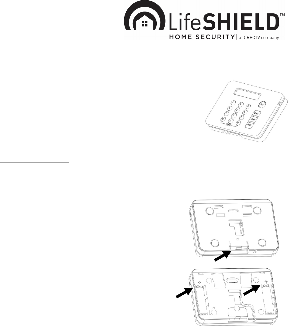
The Keypad may be wall mounted or table top mounted. The
Keypad includes 2 AA batteries installed with plastic insulating
tabs. To remove the tabs, first remove the back mounting plate by
lifting on the snap (figure 1).
Pull on the tab for each battery, making sure that the batteries
remain in place. If the batteries must be replaced, follow the marked
battery polarity (figure 2).
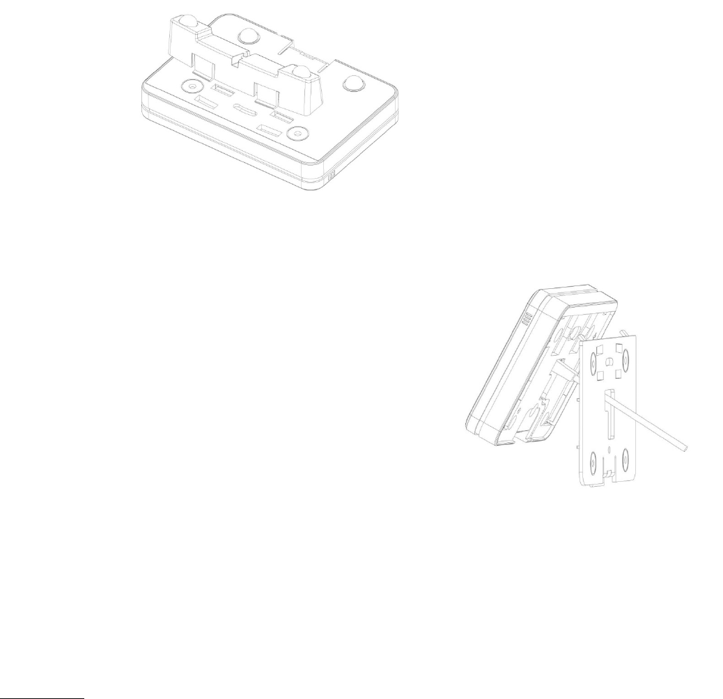
For table top placement, re-install the back mounting plate by first inserting the tabs at top of the
mounting plate and then re-snapping the bottom of the mounting plate. Snapping is easier if you
simultaneously lift on the snap while pressing down on the mounting plate. This lifts the snap over the
small detent. Next, snap the table stand onto the back housing. Make sure the table stand is oriented as
shown with the flexible tabs aligned towards the top of the Keypad (figure 3). First insert the top tabs of

the table stand into the back housing. Then apply pressure to the bottom tabs until the bottom tabs can be
inserted into the bottom housing.
For wall mount, first consider whether you plan on using the AC power adaptor. If using the AC power
adaptor, next consider how you plan to route the cord. It may be routed through the wall or hang down the
wall.
(a) If through the wall, the cord must be routed
through the opening in the back housing. In this
case, first make your hole in the wall at the desired
height. Mount the back housing to the wall with the
tabs up and the snap down, using the screws
provided, aligning the holes in the wall and the
back housing. (figure 4). Route the cord through
the wall and back housing, and insert the power
connector into the plug on rear of Keypad.
(b) If down the wall, the cord is routed through the
channel on rear of Keypad.
Next attach Keypad to the back housing by first inserting the tabs at top of the mounting plate and then re-
snapping the Keypad to the bottom of the mounting plate. Snapping is easier if you simultaneously press
on the snap while pressing down on the Keypad.
Programming
Your LifeShield system can support up to [4] Keypads in a single system. Each Keypad must be
registered into the system before use. The Keypad shipped with your Security Base was pre-registered
before shipment. Additional Keypads may be registered by using your Security Tablet, LifeShield web
portal, or LifeShield mobile application (collectively “apps”). To register a Keypad, enter the Settings tab
of the respective apps, and select Add Device. Follow the on-screen prompts. When prompted, press the

following keys simultaneously on the Keypad “1-3-7-9” for 2 seconds. The Base will respond with audio
confirmation and the apps will show a success message. If the Keypad fails to register with the Base, the
apps will show a failure message. Possible causes of registration failure include: Keypad not powered,
wrong keys pressed, Keypad out of range with Base, or too many Keypads already registered in
LifeShield System.
Using the Keypad
If the Keypad is AC powered, the display, backlight, and LED will remain on continuously. If you do not
want the backlight on continuously, press the following keys simultaneously on the Keypad “1-3-4” for 2
seconds. This will show a menu option to control backlight ON/OFF.
If the Keypad is battery powered, the Keypad will sleep within 30 seconds after the last key has been
pressed. The next time you press a key, the Keypad must obtain system status from the Security Base.
This status update may take 2 to 5 seconds to receive, and then the display and LED will show current
LifeShield system status.
After you send a command to the Security Base, the Keypad must obtain new system status. This will
again take 2 to 5 seconds, and then the display and LED will update to the new status.
To arm your LifeShield system using the Keypad, press one of Away, Stay, or Instant keys and then enter
your 4 digit code. After you have entered 4 digits, the Keypad will send the arm command to the System
Base. If you have turned on One-Touch Arming in the System Settings (using one of the apps), then a 4
digit code is not required. To use One-Touch Arming, press and hold one of Away, Stay, or Instant keys
and the Keypad will send the arm command. Note that you may only arm your system if current status is
Ready to Arm.
To disarm your LifeShield system, press the Off key then enter your 4 digit code.
If at any time, you enter wrong digits and need to re-start, simply press the desired arming key or Off, and
then your code. If you entered an invalid code, the System Base will update the Keypad display.
To use the panic mode, simultaneously press and hold the * and # buttons.
System Messages
The Keypad can display messages in either English or Spanish. To change language, press the following
keys simultaneously on the Keypad “3-7” for 2 seconds. This will show a menu option to control
language.
The Keypad includes the following messages (to be updated):
ENGLISH SPANISH
LED color (not all
messages have an
LED color)
Decription

READY TO ARM PREPARADO Solid Green
NOT READY TO ARM NO ESTÁ PREPARADO Flashing Green
DISARMED DESACTIVADO
ARMED AWAY ACTIVADO PARA SALIR Blue
ARMED STAY ACTIVADO PARA ESTAR Blue
ARMED INSTANT ACTIVACIÓN INMEDIATA Blue
EXIT DELAY SALIDA DIFERIDA Flashing Blue
ENTRY DELAY ENTRADA DIFERIDA Flashing Blue
***ALARMED*** ALARMA Flashing Red
EXIT ALARM ERROR DE SALIDA Flashing Red
***PANIC*** PÁNICO Flashing Red
INVALID CODE CÓDIGO NO VÁLIDO
INVALID COMMAND ORDEN NO VÁLIDA
SYSTEM ERROR ERROR DEL SISTEMA
KEYPAD ERROR ERROR DEL TECLADO
MESSAGE NOT SENT
MENSAJE NO ENVIADO
Command could not be transmitted
to Base. Keypad not registered or
hardware failure.
NO RESPONSE RECEIVED
NO RESPONDE
Command sent, but Base did not
respond. Keypad not registered,
hardware failure, or radio
interference.
LOW BATTERY BATERÍA DESCARGADA
ENTER CODE ENTRE EL CÓDIGO XXXX
SENDING ENVIANDO
REGISTERING PROCESANDO
PLEASE WAIT POR FAVOR ESPERE
REGISTRATION REGISTRO
SUCCESSFUL COMPLETADO
FAIL-CHANNEL BUSY FALLO-CANAL OCUPADO
FAIL-SYSTEM ERROR ERROR DEL SISTEMA
FAIL-NO TXID FALLO-NO TXID
KEYPAD READY TECLADO LISTO
SELECT LANGUAGE SELECCIONAR IDIOMA
Batteries
Replace only with AA batteries. Replace both batteries at the same time. The Keypad will detect a low
battery condition and report this via the display and via messaging to the Security Base (and then to your
phone if your account has trouble messages enabled).
Warning: the polarity of each battery must be observed. Improper handling of batteries may result in heat
generation, explosion or fire, which may lead to personal injuries. Replace only with correct batteries.
Batteries must not be recharged, disassembled or disposed in fire. Disposal of used batteries must be in
accordance with the waste recovery and recycling regulations in your area. Keep away from small
children. If batteries are swallowed, immediately see a doctor.
Transmitter and Receiver Specifications
345 MHz, Manchester encoded, 3700 bps

FCC Part 15
This equipment has been tested and found to comply with the limits for a class B digital device, pursuant
to part 15 of the FCC Rules. These limits are designed to provide reasonable protection against harmful
interference in a residential installation. This equipment generates, uses and can radiate radio frequency
energy and if not installed and used in accordance with the instructions, may cause harmful interference
to radio communications. However, there is no guarantee that interference will not occur in a particular
installation. If this equipment does cause harmful interference to radio or television reception, which can
be determined by turning the equipment off and on, the user is encouraged to try to correct the
interference by one or more of the following measures:
* Reorient or relocate the receiving antenna.
* Increase the separation between the equipment and receiver.
* Connect the equipment into an outlet on a circuit different from that to which the receiver is connected.
* Consult the dealer or an experienced radio/TV technician for help.
This device complies with Part 15 of the FCC Rules. Operation is subject to the following two conditions:
(1) This device may not cause harmful interference, and (2) this device must accept any interference
received, including interference that may cause undesired operation.
CAUTION: Changes and modifications to this product not expressly approved by Linear LLC could void
not only the user’s authority to operate this device, but also the limited warranty.
FCC ID: EF400122
Manufactured by Linear LLC for LifeShield LLC, 2021 Cabot Blvd West, Langhorne, PA 19047
[ETL listing here]