Nortek Security and Control 00178 Alarm Control Panel User Manual
Nortek Security & Control LLC Alarm Control Panel
Contents
User Manual
GC2.5 Panel
User Guide
ENGLISH
(International)
WIRELESS SECURITY SYSTEM
WARNING: OWNER’S INSTRUCTION NOTICE
Not to be removed by anyone except occupant
PRINTERS INSTRUCTIONS:
FILE: 10022313 X4 - GUIDE,USER,GO!CONTROL2.5 - INK: BLACK - MATERIAL: 20 LB MEAD BOND WITH 80 LB COATED COVER- SIZE: 5.5 x 8.5 INCH VERTICAL - SCALING 1-1 - FOLDING: ALBUM FOLD -
BINDING: SADDLE-STICH


Copyright © 2018 Nortek Security & Control
1
SYSTEM OVERVIEW ......................................................................... 4
FEATURES ........................................................................................ 4
BASIC OPERATION ................................................................................. 5
Sensor Types/Zones ....................................................................................5
Smoke, Heat, and Freeze Protection ......................................................................5
Burglary Protection ....................................................................................5
User Codes ...........................................................................................5
Alarms ...............................................................................................5
Messages.............................................................................................5
Trouble Alerts .........................................................................................5
Wireless Sensors ......................................................................................5
CONTROL PANEL FEATURES ........................................................................ 6
MAIN DISPLAY SCREENS............................................................................ 7
Home Screen..........................................................................................7
Security Screen........................................................................................7
Ready to Arm Screen ...................................................................................7
Menu Screen ..........................................................................................7
Status Screen .........................................................................................7
BURGLARY PROTECTION .................................................................... 8
SAMPLE FLOOR PLAN ..............................................................................8
SENSOR STATUS................................................................................... 9
CHECKING FOR CLOSED SENSORS ................................................................... 9
VIEWING EACH SENSOR’S STATUS................................................................... 10
DEALING WITH A SENSOR FALSE ALARM............................................................. 10
SENSOR BYPASSING .............................................................................. 11
Force Bypass All Sensors ..............................................................................11
Bypassing/Un-Bypassing Sensors .......................................................................11
STAY MODE ...................................................................................... 12
Entry Delay in Stay Mode ...............................................................................12
Quick Exit in Stay Mode ................................................................................12
SILENT CONTROL IN STAY MODE .................................................................... 12
Arming to Stay Mode ..................................................................................13
AWAY MODE...................................................................................... 13
Exit and Entry Delays in Away Mode .................................................................13
Exit Delay Restart .....................................................................................14
Silent Control in Away Mode ............................................................................14
Quick Exit in Away Mode ...............................................................................14
Auto Stay Mode . . . . . . . . . . . . . . . . . . . . . . . . . . . . . . . . . . . . . . . . . . . . . . . . . . . . . . . . . . . . . . . . . . . . . . . . . . . . . . . . . . . . . . .14
Arming to Away Mode..................................................................................14
DISARMING THE SYSTEM ..........................................................................15
Disarming from Stay Mode .............................................................................15
Disarming from Away Mode.............................................................................15
IF A BURGLARY ALARM OCCURS .................................................................... 16
Burglary Alarm Siren ..................................................................................16
Alarm Memory .......................................................................................16
Optional 2-Way Voice Communications ...................................................................16
KEY FOB: ARMING AND DISARMING ................................................................. 16
Arm with a Key Fob....................................................................................16
Away Mode...........................................................................................16
Disarm with a Key Fob .................................................................................17
Activate the Emergency Alarm ..........................................................................17
Activate the Auxiliary Output............................................................................17
TABLE OF CONTENTS

Copyright © 2018 Nortek Security & Control
2
WIRELESS KEYPAD: ARMING AND DISARMING ........................................................ 17
Arm with a Keypad ....................................................................................17
Away Mode...........................................................................................17
Disarm with a Keypad..................................................................................17
Activate a Fire Emergency ..............................................................................17
Activate a Police Emergency ............................................................................17
SMOKE, HEAT AND FREEZE PROTECTION ..................................................... 18
Initiating a Fire Alarm Manually .........................................................................18
If the Fire Alarm Sounds Automatically ...................................................................18
Silencing a False Fire Alarm ............................................................................18
RECOMMENDED FIRE ALARM LOCATIONS ............................................................ 19
NFPA Standard #72 ...................................................................................19
Do Not Mount a Smoke Alarm Here ......................................................................20
Emergency Action Plan ................................................................................20
EMERGENCY FUNCTIONS ................................................................... 21
24-HOUR EMERGENCY BUTTONS.................................................................... 21
Panic................................................................................................21
Fire .................................................................................................21
Emergency...........................................................................................21
SYSTEM TROUBLE ALERTS ................................................................. 22
TROUBLE ALERT ICON............................................................................. 22
VIEW THE CURRENT TROUBLE ALERTS .............................................................. 22
TROUBLE ALERT BEEP HOLD-OFF .................................................................. 22
SYSTEM STATUS ICONS..................................................................... 23
AC POWER ON.................................................................................... 23
TEST MODE ...................................................................................... 23
AC POWER OFF ................................................................................... 23
TOUCH SCREEN KEYPAD TRAFFIC................................................................... 23
SOUNDER DISABLED .............................................................................. 23
CELL RADIO...................................................................................... 23
LOW BACKUP BATTERY ............................................................................ 23
INTERIOR SENSOR OPEN ..........................................................................23
MESSAGING .............................................................................. 24
DISPLAYING MESSAGES ...........................................................................24
READING MESSAGES .............................................................................. 24
READING CONFIDENTIAL MESSAGES ................................................................ 25
FILTERING MESSAGES............................................................................. 25
SORTING MESSAGES .............................................................................. 25
SYSTEM TOOLBOX ......................................................................... 26
USER MANAGEMENT .............................................................................. 26
User Code Setup ......................................................................................26
Adding a User Code ...................................................................................26
User Code Validity.....................................................................................26
User Code Access Schedules............................................................................26
Adding/Editing User Access Schedules ...................................................................26
Recurring User Access Schedules .......................................................................27
Date User Access Schedule .............................................................................27
Date Range User Access Schedule .......................................................................27
Deleting User Access Schedule..........................................................................27
User Codes ..........................................................................................27
Deleting a User Code ..................................................................................28
Duress User Code Setup ...............................................................................28
Setting the Duress User Code ...........................................................................28

Copyright © 2018 Nortek Security & Control
3
Secret Duress Button ..................................................................................28
SYSTEM HISTORY ................................................................................. 29
SYSTEM TEST .................................................................................... 29
Sensor Test ..........................................................................................30
Panel Test ...........................................................................................30
CHIME SETUP .................................................................................... 30
ADJUSTING THE BRIGHTNESS/VOLUME .............................................................. 31
ADJUSTING THE BACKLIGHT TIMEOUT ............................................................... 32
CLEANING THE TOUCH SCREEN .................................................................... 32
SET DATE AND TIME............................................................................... 32
DISPLAY FIRMWARE VERSION ...................................................................... 33
DEALER INFO SCREEN AND CALL BACK BUTTON ...................................................... 33
Accessing the Dealer Info Screen ........................................................................33
Requesting a Service Call Back..........................................................................33
INSTALLER PROGRAMMED OPTIONS ......................................................... 34
Siren Run Time .......................................................................................34
Sensor Trigger Limit ..................................................................................34
Fire Horn Run Time ...................................................................................34
Exit Delay............................................................................................34
Entry Delay ..........................................................................................34
24-Hour Emergency Functions ..........................................................................34
Quick Arming.........................................................................................35
Quick Bypass .........................................................................................35
Quick Exit............................................................................................35
Auto Un-bypass.......................................................................................35
Auto Stay ............................................................................................35
Key Fob Sound........................................................................................35
Key Fob Disarm After Sound . . . . . . . . . . . . . . . . . . . . . . . . . . . . . . . . . . . . . . . . . . . . . . . . . . . . . . . . . . . . . . . . . . . . . . . . . . . .35
Key Fob Options ......................................................................................35
Wireless Keypad Emergency Keys .......................................................................36
Exit Delay Restart .....................................................................................36
Cancel Display........................................................................................36
Cancel Time..........................................................................................36
Dialer Delay..........................................................................................36
2-Way Voice . . . . . . . . . . . . . . . . . . . . . . . . . . . . . . . . . . . . . . . . . . . . . . . . . . . . . . . . . . . . . . . . . . . . . . . . . . . . . . . . . . . . . . . . . .36
INSTALLER SPECIFIC INFORMATION ......................................................... 37
User Codes ..........................................................................................37
Zones ...............................................................................................38
SERVICE INFORMATION ....................................................................39
REGULATORY INFORMATION ................................................................ 40
Wireless Product Notice................................................................................40
FCC Notice ...........................................................................................40
IMPORTANT NOTICE .......................................................................41
ALARM SYSTEM LIMITATIONS....................................................................... 41
Panel Operating Conditions.............................................................................41
LIMITED WARRANTY ....................................................................... 42

Copyright © 2018 Nortek Security & Control
4
GC2.5 Wireless Security System | User Guide
SYSTEM OVERVIEW
This system provides three (3) forms of protection: burglary, re, and emergency, depending on the options set by your
installer. The system consists of a Control Panel with a color touch screen, wireless sensors that provide perimeter and
interior burglary protection, and wireless smoke and carbon monoxide detectors. In addition, optional remote control key
fobs, wireless panic buttons and keypads may have been provided or installed.
The system monitors all protection “zones” and the system’s status. The Control Panel displays monitoring information
and controls the alarm siren. Your system may have also been setup to send alarm and status reports to a Central Station
and may have the capability for 2-way voice communications with the alarm monitoring operator.
FEATURES
The following is a list of standard features and options that can be included in your system. Ask your installer which
options are available, and check the boxes that apply.
●Stay and Away arming modes: Stay mode arms the system perimeter only and is used typically at night when
the premises are occupied. Away mode arms the system perimeter and interior; it is used when the premises are
unoccupied.
●60 user-unique 4-digit codes to operate the system: The system supports one (1) master user code that can
assign and maintain the other user codes.
●One of the 60 user codes functions as a duress code. Controlling the system with this code gives the appearance of
normal operation, but using it sends a silent duress report to the Central Station to initiate a silent alarm call for help.
●Voice announcements from the Control Panel: The system has a vocabulary of descriptive words that can be
assigned to sensors so each has a unique announcement such as “front door” or “bedroom window” if desired.
●Home automation with the built-in Z-Wave controller for remote control of Z-Wave enabled home appliances (optional
feature).
●Alarm history with system event log: Each alarm and system alert is logged into the system’s memory. These
events can be displayed and reviewed at the Control Panel or reviewed remotely by the Central Station.
●Real-time clock and calendar appears on the system’s display and is used to time stamp items in the event log.
2-way voice communication: After an alarm, the system can automatically connect with a Central Station operator
to converse with people in the premises.
Remote control of the system using a Web-enabled device through the Internet.*
Three optional 24-hour emergency functions: Panic, Fire, and Emergency. These functions can be activated
by pressing buttons on the Control Panel, using wireless sensors, using the wireless keypad or using portable
pendant devices (such as the panic button remote).
* Requires the optional Cellular Radio Module.

Copyright © 2018 Nortek Security & Control
5
GC2.5 Wireless Security System | User Guide
BASIC OPERATION
The following are general operational concepts that your
system supports. Understanding these concepts will help
you to use your security system to its fullest extent.
Sensor Types/Zones
The system’s wireless sensors have been assigned to
selected “types” (often called “zones”). The sensor type
determines how and when the system will react to a signal
from the sensor. Some sensors are armed 24 hours a day.
Other sensors are armed only when the system is armed.
Smoke, Heat, and Freeze Protection
If wireless smoke, heat, and freeze detectors have been
installed in your system, they are armed 24 hours a day.
They will sound an alarm when smoke is detected and can
report the re alarm to the Central Station. See “Smoke,
Heat and Freeze Protection” on page 18 for emergency
planning and evacuation information.
Burglary Protection
Burglary protection is provided by perimeter and interior
sensors. When the system is armed in the Away mode,
both perimeter and interior sensors are armed and can
trigger an alarm. When the system is armed in the Stay
mode, only the perimeter sensors are armed and can
trigger an alarm.
Both arming modes offer an Exit Delay that allows time
to exit the premises without triggering the alarm. Upon
re-entry, an Entry Delay is enabled that allows you time to
disarm the system.
You can set sensors to sound a chime and/or a voice
announcement when they are triggered. This allows you
to monitor your doors and windows while the system is
disarmed.
For more details, see “Burglary Protection” on page 8.
User Codes
The system installer has already programmed a master
user code for your system. This code can be used to
control the system as well as assign and change the other
user codes. The master user code can also access several
system setup settings in the User Toolbox.
Alarms
When an alarm occurs, the Control Panel’s siren and an
external siren (if installed) sound for a preset period of time.
During active alarms and after disarming, the alarm history
button displays all the activated alarms and the sensors
that were involved. The alarm history clears the next time
the system is armed or can be cleared manually.
Messages
Your security system supports receiving messages from
the Central Station. The messages detail system upgrades,
additional services, special regional weather alerts, etc.
Trouble Alerts
The system monitors itself for abnormal operating
conditions and will alert you if trouble is detected. Trouble
conditions can be reported to the Central Station.
Wireless Sensors
Your security system comes with wireless sensors. Some
sensors are visible, but others may be hidden by door-
jambs or where the sensor is mounted. Depending on your
type of installation and the amount of sensors installed with
the Control Panel, sensors can include but are not limited
to the following:
Door/Window Sensor
Glass Break Sensor
CO Sensor
Key Fob
Motion Detector
Smoke/Heat/Freeze Alarm
Panic Remote Button
Wireless Touch Screen Keypad
System Overview
Copyright © 2018 Nortek Security & Control
6
GC2.5 Wireless Security System | User Guide
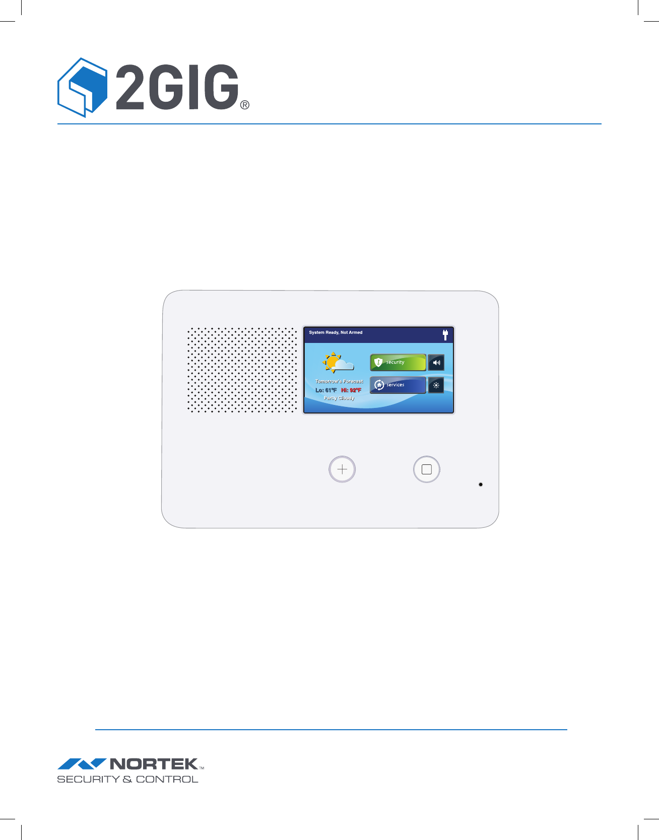
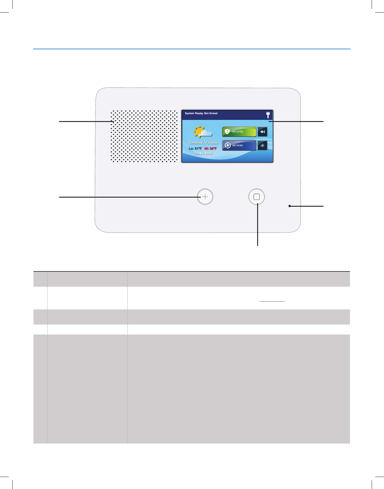
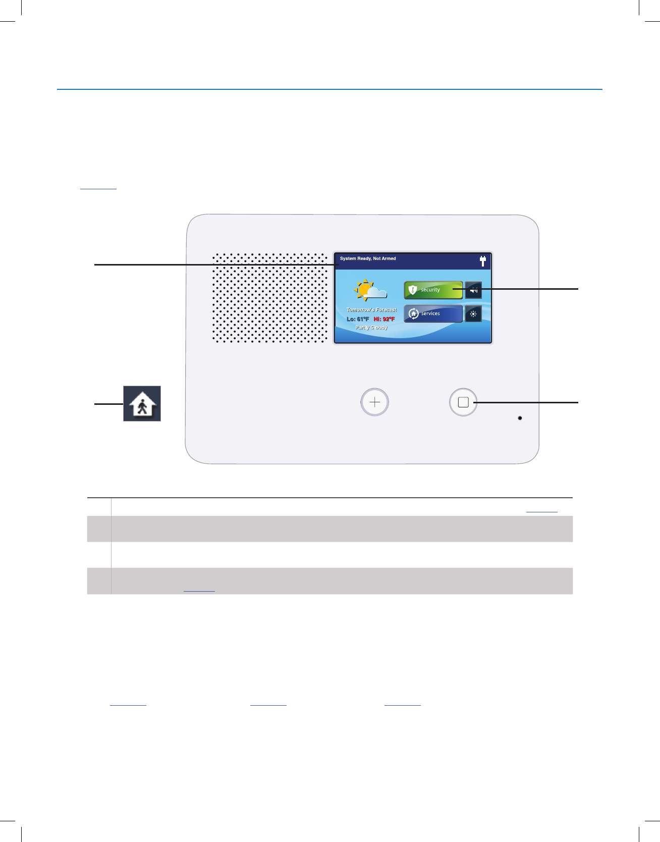
CONTROL PANEL FEATURES
See the table below for full descriptions of Control Panel Features.
A
C
B
D
E
AAlarm Sounder and Speaker Sounds all system local alarms, voice prompts, system sounds, and audio for two (2)-way
voice communications with the Central Station
BColor Display with Touchscreen
Displays all system information, status, programming, and functions as the keypad.
The display cycles clock, calendar, and weather with an Alarm.com account (tap manually to
change)
CEmergency Button/Indicator Illuminates WHITE when enabled for emergency alarms and flashes during emergency
alarms
DMicrophone Used for voice communication with the Central Station
EHome Button/Indicator
Sensor Status
Illuminates BLUE when all sensors are closed (Ready to Arm)
Not lit when any sensor is open (not Ready to Arm)
Arming Status
Illuminates RED when system is armed
Flashes RED during the Entry Delay
Alarm Memory
Flashes RED during an alarm
Flashes RED after an alarm while system is still armed
Power Outage
Flashes WHITE during power outage (system on battery backup)
Flashes BLUE when all sensors are closed (Ready to Arm)
Flashes ORANGE when any sensor is open (not Ready to Arm)
Flashes RED while system is armed
System Overview
Copyright © 2018 Nortek Security & Control
7
GC2.5 Wireless Security System | User Guide
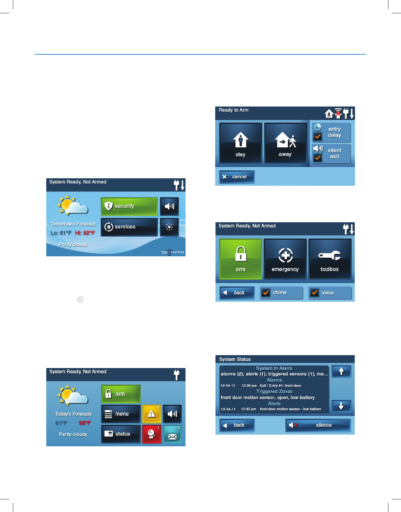
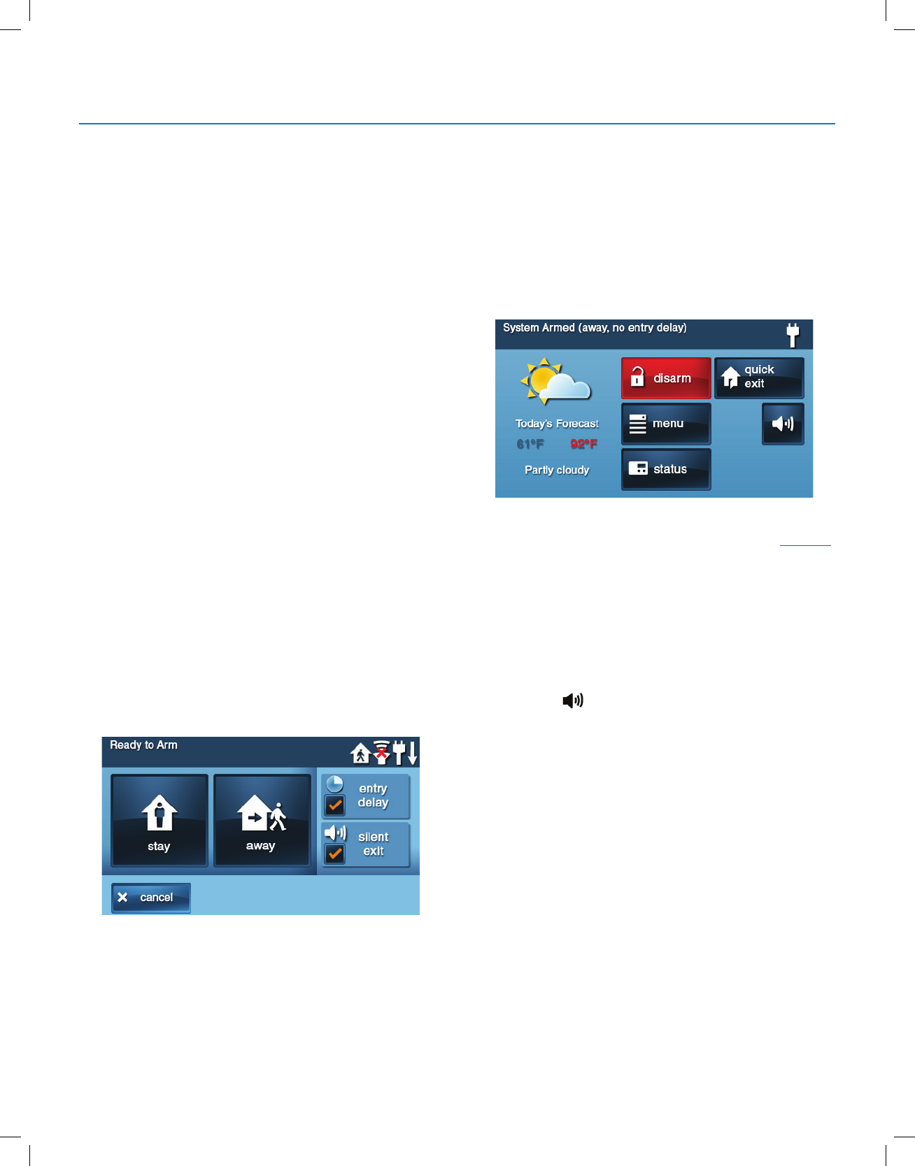
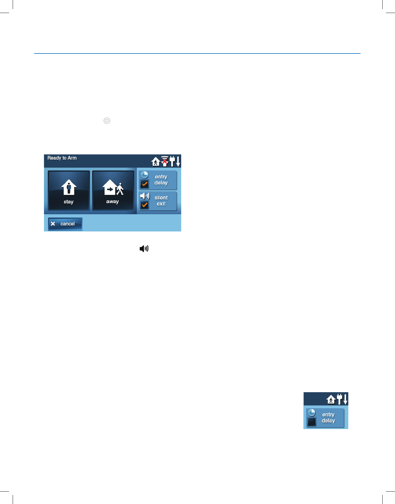
Ready to Arm Screen
Use the Entry Delay screen to arm the security system in
Stay and Away mode. You also have the option to select
the Entry Delay and Silent Exit check boxes to turn those
features ON.
Menu Screen
Use the Menu screen to gain access to the Entry Delay,
Emergency, or Toolbox screen.
Status Screen
Use the controls in the Status screen to view the system’s
current status and to review a scrolling list of alerts in a log
format. The date, time and nature of any alerts are listed in
the displayed log.
●Tap the Silence button to stop the system status voice
announcement.
●Tap the or arrows to scroll through the list status
messages.
MAIN DISPLAY SCREENS
Use the touch screen to control and operate the Control
Panel. The touch screen includes a variety of buttons,
indicators, and text for navigation and system operation.
At the top-left of the Home screen, you can view the current
system state. Scrolling text shows any pending alerts. The
right side of the screen reveals a variety of system status
icons.
Home Screen
The Home screen shows system status with icons to
indicate system conditions. It also displays the time and
date. The Home screen has Security, Services, Silent
Control and Display Off buttons.
TIP: Tap the Services button to access features for
controlling Z-Wave devices. If Z-Wave features are not
programmed, this button will not appear.
Tap the Home button on the panel to reveal the Home
screen.
Security Screen
Use the Security screen to access the Arm, Menu, and
Status screens. This screen also shows the current time
and date. If messages, alarms, or trouble alerts are
pending, square buttons indicate the number of pending
alarms or messages.
System Overview
Copyright © 2018 Nortek Security & Control
8
GC2.5 Wireless Security System | User Guide
BURGLARY PROTECTION
When your system was set up by your installer, wireless sensors were placed to monitor specic doors and windows. The
installer selected these doors and windows as likely places where an unlawful intrusion may occur and be detected. Each
sensor was programmed to have the system react in a specic way. See "Installer Programmed Options" on page 34 for
specics about each sensor.
Some sensor types (such as smoke detectors, carbon monoxide detectors, panic buttons, etc.) are always active and can
trigger an alarm at any time. Other sensors on protected doors and windows are part of the burglary protection part of the
system that can be turned on or off. Turning on the burglary protection part of the security system is called “Arming the
System". The burglary protection part of the system can be armed in two modes: Stay mode or Away mode.
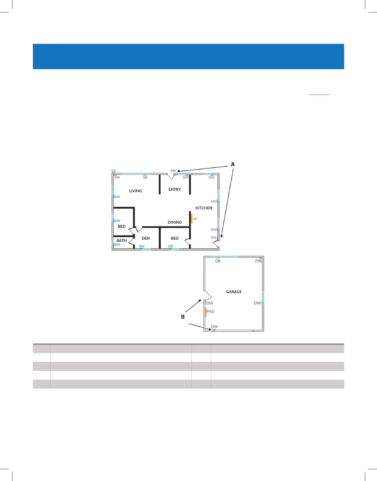
SAMPLE FLOOR PLAN
Refer to the oor plan below. It shows a typical residential installation and the various types of wireless sensors and their
functions.
AFront and side door sensors have Exit/Entry Delay SMKE Smoke detector
BSide and main garage door sensors have Exit/Entry Delay CO Carbon monoxide detector
CP Control panel GB Glass break sensor
DW Door/window sensor PAD Wireless keypad
PIR Motion detector ES External siren
IMPORTANT: Security systems installed in a commercial location are for use only as a burglar alarm system and not for
re protection. This security system has been evaluated and complies with UL 1610. For commercial installations (UL
1610), only one method of communication is to be used. This method of communication is a Cell Radio Module.

Copyright © 2018 Nortek Security & Control
9
GC2.5 Wireless Security System | User Guide
SENSOR STATUS
The security system constantly monitors all of the sensors attached to the protected doors and windows in your home or
business. The Control Panel knows if each door or window with sensors is open or closed. The open or closed condition
of the protected doors and windows is called the sensor status.
For maximum security, all the doors and windows on your premises should be closed when you leave the building. In
some cases, such as when using the security system when you stay at home, you may want to leave some doors or
windows open. The system recognizes bypasses to resolve the open doors or windows. See "Bypassing/Un-Bypassing
Sensors" on page 11.
NOTE: Before you can arm the system, you must close or bypass all doors and windows with sensors.
CHECKING FOR CLOSED SENSORS
In most cases, you will be arming the security system with all of the sensor-protected doors and windows closed. The
Control Panel provides easy ways to verify that all the sensor-protected doors and windows are closed before arming the
system:
●The Home button lights green when all perimeter sensors are closed. The Home button is not lit if any
perimeter sensor is open. Open interior sensors do not change this indication.
●The Security button on the display’s Home screen lights green when all perimeter sensors are closed. The Security
button lights orange if any perimeter sensor is open. Open interior sensors do not change this indication.
●The Arm button on the display’s Security screen and Menu screen lights green when all perimeter sensors are
closed. If any interior sensors are open (or when any motion detector is triggered), a house icon displays on the
status bar. The Arm button lights orange if any perimeter sensor is open.
Burglary Protection
Copyright © 2018 Nortek Security & Control
10
GC2.5 Wireless Security System | User Guide
VIEWING EACH SENSOR’S STATUS
The Control Panel will also show you which sensor-protected doors and windows are open. Your installer has
programmed descriptive names for each sensor-protected door and window. The Control Panel’s color display will show
the names of which doors and windows are open.
●The top of the display on the Home, Security, and Menu screens shows sensor status. See “System Status Icons” on
page 23. Tapping the Status button also displays a list of open sensors and general system status and alerts.
A
D
B
C
AThe Status Bar shows the system mode and shows system status icons. See “System Status Icons” on page 23.
BThe Arm button on the Security and Menu screens lights green when all perimeter sensors are closed. The Arm
button lights orange if any perimeter sensor is open.
CThe Home button lights blue when all perimeter sensors are closed. The Home button is not lit if any perimeter
sensor is open.
DThe icon displayed shows that an interior sensor is open. Other icons can appear here as well. See “System
Status Icons” on page 23.
DEALING WITH A SENSOR FALSE ALARM
When armed, the Control Panel reports alarm conditions on all sensors, both visually (on the status bar, and
through a system alert icon) and audibly (through voice and chime announcements). There are rare times
when an sensor will send a false alarm condition to the Control Panel. The conditions of a false alarm vary
depending on the type of sensor and how that sensor communicates with the Control Panel.
● Perform a System, Sensor, and Panel Test to nd any false alarm conditions. See "System Test" on
page 29. See "Sensor Test" on page 29. See "Panel Test" on page 30.
Burglary Protection
Copyright © 2018 Nortek Security & Control
11
GC2.5 Wireless Security System | User Guide
SENSOR BYPASSING
Before the system can be armed, all protected doors
and windows must be closed or bypassed. You can
bypass open sensors on protected doors or windows
before arming the system. When a sensor is bypassed,
the system ignores that the door or window is open. Two
types of sensor bypasses are available:
●Forced
●Manual
In some cases (such as when using the security system
for protection when staying at home), it may be desirable
to leave some sensor-protected doors or windows open.
Temporarily bypassing a sensor for this situation is called
Force Bypassing.
NOTE: Force bypasses are automatically removed when
the system is disarmed.
Sensor bypassing is also sometimes used when a sensor
requires service. A sensor’s magnet may be missing, or
an external switch contact connected to a sensor may be
faulty. This causes the sensor to report as open to the
Control Panel.
In these conditions, you may need to schedule a service
call with your qualied alarm service technician to repair or
replace the troubled sensor. If the security system needs
to be armed before the sensor can be serviced, the sensor
can be manually bypassed so the rest of the system can
be armed. Depending on programming, manual bypasses
can remain in place until they are manually removed.
NOTE: Bypassed Sensors offer no protection and cannot
cause an alarm. Use Bypass if you want to arm your
system with one or more sensors open and intentionally
unprotected.
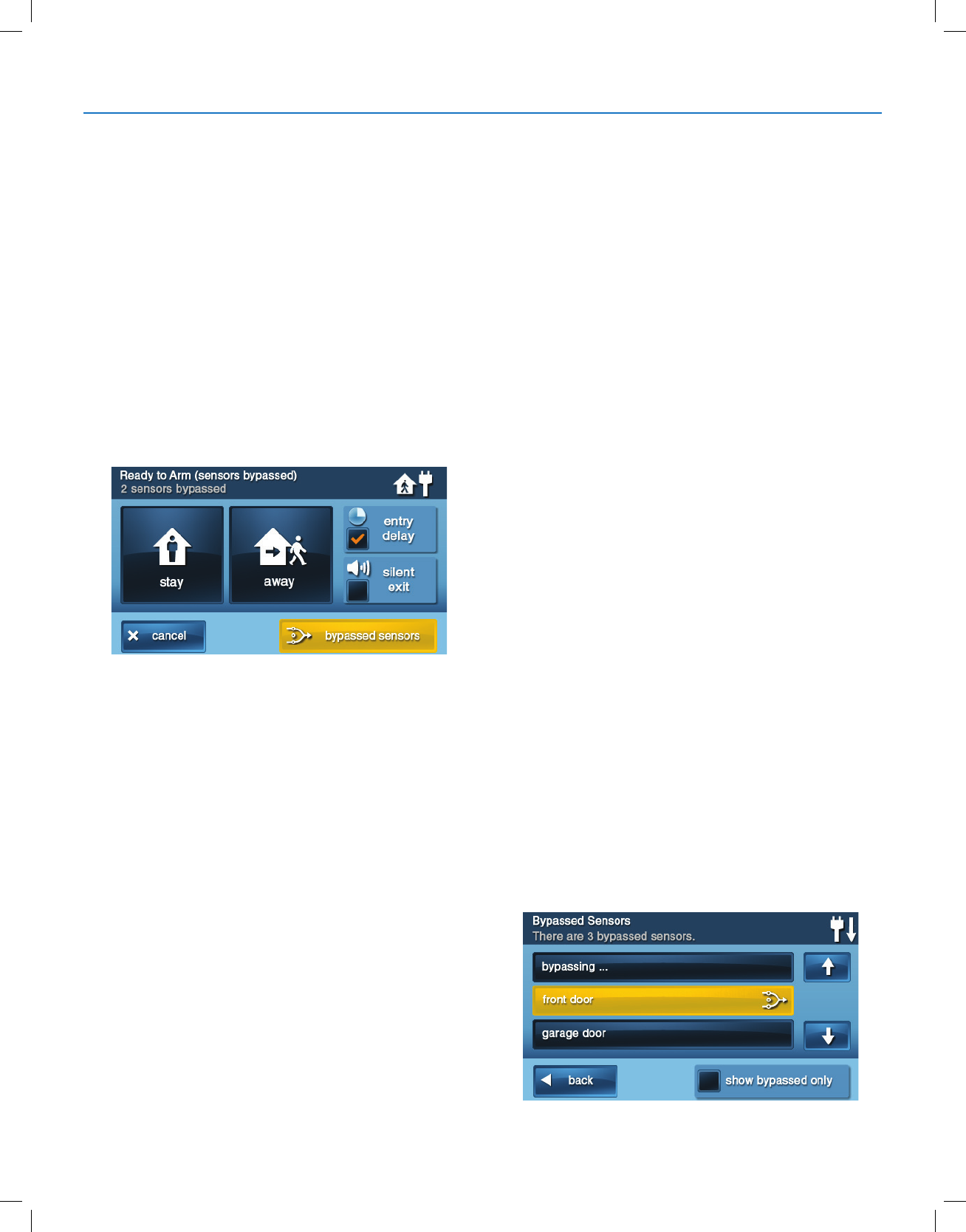
Force Bypass All Sensors
If any sensors are open when the system is disarmed,
the Arm button on the panel turns YELLOW. When you
tap the Arm button, the system automatically reveals
the Bypass screen which lets you arm the system while
forcing it to bypass all open sensors.
To force bypass all open sensors:
1 Ensure a sensor is open, such as a door or window.
2 At the Security or Menu screen, tap the YELLOW Arm
button.
3 At the Bypass screen, tap Bypass All. This forces the
system to bypass all of the open sensors in the list,
including any open interior sensors.
4 At the Enter Code screen, enter a valid user code to
bypass the sensor.
NOTE: The Quick Bypass feature can also be
congured by the installer. For details, refer to the
Control Panel’s Installation & Programming Guide.
5 At the Ready to Arm (Sensors Bypassed) screen, tap
Stay or Away.
Later, when you disarm the system, the bypassed sensors
are returned to their normal state.
Bypassing/Un-Bypassing Sensors
To add or remove sensors on the system’s bypass list:
1 At the Home screen, tap Menu.
2 At the Menu screen, tap Toolbox.
3 Enter a valid user code to gain access to the Toolbox.
4 At the Toolbox (1 of 3) screen, tap Bypassed
Sensors.
5 At the Bypassed Sensors screen, choose one of
these options:
●Adding a sensor to the bypassed list. Tap the
BLUE button that corresponds to the desired
sensor. When the button turns YELLOW, the
system will bypass the sensor.
●Viewing Only Bypassed Sensors. Place a
check-mark in the Show Bypassed Only box.
●Removing a sensor from the bypassed list.
Tap the YELLOW button that corresponds to the
desired sensor. The button turns BLUE when it is
no longer on the bypassed list.
6 When nished, tap Back.
Burglary Protection
Copyright © 2018 Nortek Security & Control
12
GC2.5 Wireless Security System | User Guide
STAY MODE
Use Stay mode to partially arm the system when
individuals will be occupying the premises. This arms
only the sensor-protected perimeter doors and windows.
This leaves interior motion sensors or other interior doors
unarmed.
In a home setting, Stay mode is typically used during the
evening hours when occupants are no longer expected
to leave or enter the premises. This allows occupants to
move about the premises without triggering the burglary
alarm. Because all the interior burglary protection is OFF,
an alarm would only be triggered when a sensor-protected
perimeter door or window is opened.
Entry Delay in Stay Mode
Certain sensors, such as a door, can be congured by
your installer to use a delay timer before triggering an
alarm.
This provides a way for an authorized person to enter
using a predetermined door to disarm the system before
an alarm is triggered.
To arm the system using an Entry Delay:
1 At the Security or Menu screen, tap the Arm button.
2 At the Ready to Arm screen, place a check-mark in
the Entry Delay box. This is the default setting.
NOTE: If you un-check the Entry Delay box, an alarm
will be triggered when the sensor is opened while
armed in Stay mode.
3 Tap Stay to arm the system
NOTE: When re-entering the premises, the user must
enter through the door(s) programmed to use the Entry
Delay timer. This gives the user a specied amount of
time to disarm the system. If the system is not disarmed in
time, an alarm is triggered.
Quick Exit in Stay Mode
A programmable option, called Quick Exit may be
displayed on the Security screen while the system is
armed in Stay mode. Tap the Quick Exit button to start
a timer that allows someone to exit or enter through
a sensor-protected door that is programmed for delay
without having to disarm the entire system. When the
delay timer runs out, the system returns to the normal
Stay mode.
The Quick Exit option can be turned ON or OFF by the
installer. See "Installer Programmed Options", on page 34,
to understand the options that have been programmed for
your system.
SILENT CONTROL IN STAY MODE
Three options for silencing the beeps and announcements
are available when arming or disarming the system in
Stay Mode.
●At the Home or Security screen, tap the Silent
Control button.
●At the Ready to Arm screen, check the box adjacent
to the Silent Exit option.
●On the Exit Delay screen, tap Silence.
Selecting any of these options silences the Control Panel
beeps and announcements. When arming, selecting the
option doubles the length of the Exit Delay.
Burglary Protection
Copyright © 2018 Nortek Security & Control
13
GC2.5 Wireless Security System | User Guide
Arming to Stay Mode
Use Stay Mode to arm the system when anyone is at
home. Stay Mode normally has an Entry Delay so a user
with a user code can re-enter without causing an alarm.
1 Close all protected perimeter doors and windows
before arming.
2 Verify that the Home button on the Control Panel
illuminates GREEN, indicating that the system is
ready to arm. The Security and Arm buttons on the
display are GREEN when all sensors are closed.
NOTE: If you want to arm the system quietly without
sounding any announcements, tap before
performing these steps:
●At Ready to Arm screen, check the box adjacent to
the Silent Exit option.
Or
●During Exit Delay tap Silence.
3 At the Security or Menu screen, tap Arm.
NOTE: If any perimeter door or window sensors
are open, the Bypass screen appears. Close all the
sensors displayed, or tap Bypass All to force bypass
the displayed sensors.
NOTE: Bypassed sensors do not trigger an alarm. To
bypass sensors, enter a user code unless the installer
has set the system for Quick Bypass.
4 On the Ready to Arm screen, check the Entry Delay
box when arming the system in Stay mode.
If no one is expected to re-enter, the system can be
armed without an Entry Delay. All perimeter doors will
trigger the alarm instantly. To arm with instant alarms
for all exit/ entry perimeter doors, un-check the box
adjacent to the Entry Delay option.
5 Tap Stay to arm the system.
NOTE: To arm the system, you may need to enter a
user code if your installer has turned off the system’s
Quick Arming feature.
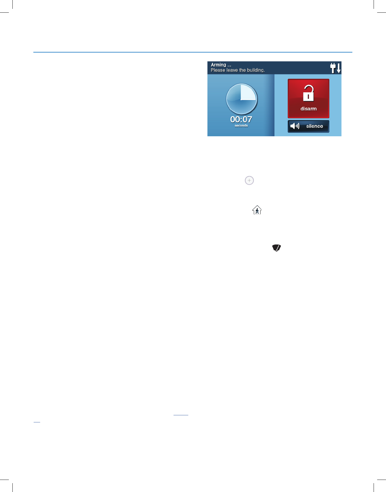
6 The system will arm and shows the Exit Delay
counting down. When the Exit Delay expires, the
system is fully armed in the Stay mode.
AWAY MODE
Away mode is for arming the system when everyone
is leaving the premises. Away mode arms all sensor-
protected perimeter doors and windows, interior motion
sensors, interior glass break sensors and any other
sensor-protected interior doors. The premises must be
unoccupied while the system is armed. Away mode is
typically used for arming the system during the daytime
hours in a residential location, and non-business hours in
a commercial location.
When the system is armed in Away mode, you cannot
move about the premises without triggering the burglary
alarm (if the system is installed with interior motion
detectors). An alarm also occurs if any sensor-protected
door or window is opened or glass breakage is detected (if
glass breakage detectors are installed in your system).
Exit and Entry Delays in Away Mode
Certain sensors, such as a door, can be setup by your
installer to have a delay before triggering an alarm. This
provides a way for an authorized person to exit and re-
enter the premises without triggering an alarm.
●Exit Delay allows time to leave after arming the
system.
●Entry Delay allows time to enter and disarm the
system before an alarm is triggered.
When arming the system in Away mode, an Entry Delay
check box is shown on the Arming screen. By default, this
option is checked, so the programmed delay doors allow
time for disarming the system after the door is opened. If
you clear the Entry Delay box, the delayed alarm trigger is
removed from all sensor-protected doors programmed for
delay. Those entrances instantly trigger an alarm if they
are opened in Away mode.
NOTE:
With the Entry Delay disabled,
you must remotely disarm the
system with a wireless key fob
before entering.
Burglary Protection
Copyright © 2018 Nortek Security & Control
14
GC2.5 Wireless Security System | User Guide
Exit Delay Restart
The Exit Delay Restart option extends the Exit Delay one
time if you need to re-enter the premises. With the Exit
Delay Restart option, when you re-enter the premises after
you have left, but before the Exit Delay timer expires, the
Exit Delay timer restarts, giving you the full length of time to
leave again.
TIP: The Exit Delay Restart option only works once, each
time the system is armed.
Silent Control in Away Mode
Three options for silencing the beeps and announcements
are available when arming or disarming the system in Away
mode.
●On the Control Panel’s Home and Security screens, a
Silent Control button is displayed.
●On the Arming screen, a Silent Exit check box is
displayed.
●On the Exit Delay screen, a Silence button is
displayed.
Selecting any of these options silences the Control Panel
beeps and announcements. When arming, selecting Silent
Control doubles the length of the Exit Delay.
Quick Exit in Away Mode
A programmable option called Quick Exit may be displayed
on the Security screen while the system is armed in the
Away mode. Tapping the Quick Exit button starts a timer to
allow someone to exit or enter through a sensor-protected
door programmed for delay without having to disarm the
entire system. When the delay timer runs out, the system
returns to the normal Away mode.
TIP: If interior sensors are installed in the system in certain
areas, do not violate those sensors when using the Quick
Exit feature in Away mode.
Auto Stay Mode
The system may have been programmed by the installer
for Auto Stay mode. If this option is on and the system is
armed in Away mode, if an Exit/Entry Delay sensor is not
triggered before the Exit Delay expires (no one leaves the
premises), the system automatically arms in Stay mode
instead of Away mode.
NOTE: Quick options can be turned on or off by your
installer. Refer to "Installer Programmed Options", on page
34, to see which options have been set for your system.
Arming to Away Mode
Use the Away mode to arm the system when everyone
will be leaving the home. The Away mode normally has
an entry delay so someone with a user code can re-enter
without causing an alarm. Interior and perimeter sensors
are armed in the Away mode.
1 Close all sensor-protected doors and windows before
arming.
2 Verify that the button on the Control Panel is
illuminated green, indicating that the system is Ready
to Arm. The Security button and Arm button on the
display will also be green when all perimeter sensors
are closed. If the icon is displayed on the status
bar, an interior sensor is open. Make certain to close or
manually bypass the interior sensors or an alarm will
occur.
3 To arm the system quietly without sounding any
announcements, tap the button before performing
the next steps:
●At the Arming screen check the Silent Exit box
Or
●During the Exit Delay, tap Silence
4 At the Security screen, or the Menu screen, tap Arm.
NOTE: If any perimeter door or window sensors are
open, the Bypass screen appears. Close all the sensors
displayed or tap Bypass All to force bypass the displayed
sensors.
NOTE: Bypassed sensors do not trigger an alarm.
To bypass sensors, enter a user code unless the installer
has set the system for Quick Bypass.
5 On the Arming screen, the Entry Delay check box
option can be used with Away mode.
●The system can be armed without an Entry Delay.
All perimeter doors trigger the alarm instantly. The
system has to be disarmed with a wireless key
fob. To arm with all exit/entry perimeter doors as
instant, clear the Entry Delay check box.
6 Tap Away.
To arm the system, enter a user code if your installer
has turned off the system’s Quick Arming feature.
Burglary Protection
Copyright © 2018 Nortek Security & Control
15
GC2.5 Wireless Security System | User Guide
7 The system arms and shows the Exit Delay counting
down. When the Exit Delay expires, the system is fully
armed in the Away mode.
NOTE: When the system is armed in the Away mode,
beeps sound during the Exit Delay (these beeps
become faster during the last 10 seconds).
DISARMING THE SYSTEM
To stop the Control Panel from triggering burglary alarms,
the system needs to be disarmed. Disarming turns off the
burglary detection part of the system for sensors that are
not 24-hour sensors. Disarming also stops any type of
alarm in process.
Disarm the system from Stay mode before exiting the
premises. The system should be disarmed from Away
mode before or while entering the premises. When
disarming from the Control Panel or wireless keypad, enter
a valid user code. A wireless key fob can also be used to
disarm the system. Entering a user code is not required
when disarming with a wireless key fob.
An important feature of the Control Panel is its ability to
warn you if an alarm has occurred while you were away.
If an alarm was triggered while the system was armed,
the alarm siren runs for a preset length of time then
stops. When you enter to disarm the system, instead of
sounding the normal Entry Delay beeps, the Control Panel
sounds repeated fast beeps to warn you that an alarm has
occurred while you were away.
When you enter your home to disarm the
system, if you hear fast repeated beeps instead
of the normal Entry Delay beeps, use Extreme
Caution! An intruder may still be present inside
the building! Wait outside and use a Cell Phone
to call law enforcement for assistance.
Disarming from Stay Mode
Disarm the system from Stay mode before exiting the
premises.
1 At the Home screen, tap for Silent Control.
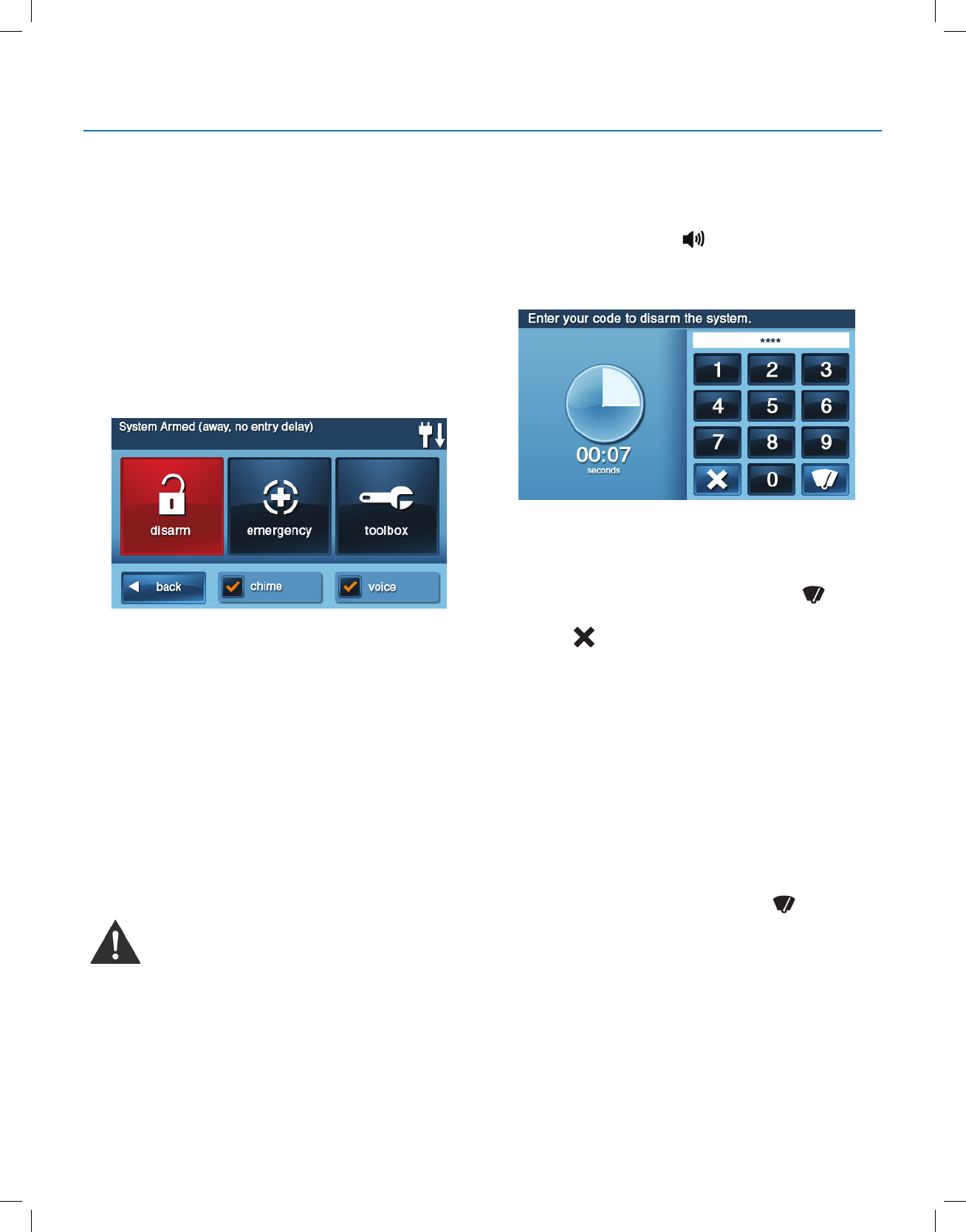
2 At the Security screen or the Menu screen, tap Disarm.
This action displays the Disarm Code screen.
3 The left side of the screen shows any events that have
occurred while the system was armed.
4 Enter a valid user code to disarm the system.
●In the event you tap the wrong key, the button
erases the entire entry.
●Tap if you decide to not disarm the system at
this time.
Disarming from Away Mode
The system should be disarmed from Away mode while
entering the premises.
1 Enter the premises through a designated Entry Delay
sensor-protected door.
2 The Disarm Code screen displays on the Control Panel
and the Entry Delay beeps sound. The left side of the
screen shows events that have occurred while the
system was armed.
3 Enter a valid user code to disarm the system.
●In case you tap the wrong key, the button
erases the entire entry.
Burglary Protection
Copyright © 2018 Nortek Security & Control
16
GC2.5 Wireless Security System | User Guide
IF A BURGLARY ALARM OCCURS
If an armed sensor is tripped while the system is armed
in the Stay or Away mode, an alarm occurs and the siren
sounds. Delayed sensors start the Entry Delay to allow time
to disarm the system. Instant sensors trigger the alarm right
away. Most sensors trigger the alarm siren, some sensors
may be set to trigger a silent alarm without sounding the
siren.
Burglary Alarm Siren
If a burglary alarm is tripped while the system is armed, the
Control Panel sounds the alarm siren for a preset time (see
"Installer Programmed Options" on page 34). After the time
expires, the siren will stop.
The system limits the number of times a sensor can re-
trigger an alarm while the system is armed. The setting
is one to six times per sensor, per arming period (see
"Installer Programmed Options" on page 34).
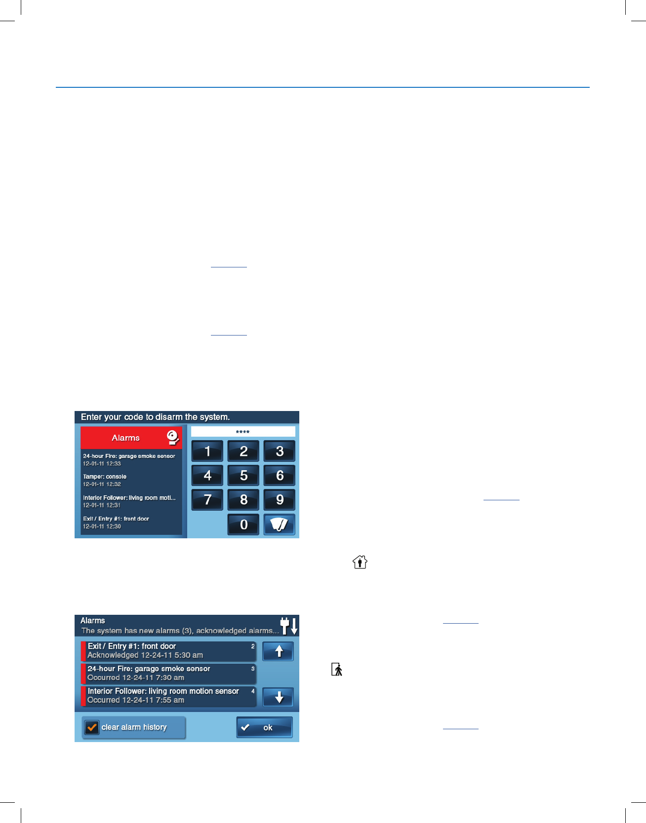
Alarm Memory
If an alarm has occurred while the system was armed, the
Disarm screen shows the time and date of the alarm and
the sensor(s) that triggered the alarm.
After the system is disarmed, the Alarm Memory screen
appears. The Alarm Memory screen shows the sensor(s)
that caused the alarm. If more than one sensor was
triggered, the display shows the order in which the alarms
occurred.
The alarm memory automatically clears the next time the
system is armed. You can also check the Clear Alarm
History box and tap OK to manually clear the alarm
memory (24-hour re and CO sensors that are still violated
remain in alarm memory).
Optional 2-Way Voice Communications
2-way voice communications provides a method for alarm
verication and can provide emergency assistance. The
Control Panel contains a built-in microphone that can
monitor sounds around the area of the Control Panel.
The built-in microphone and speaker allow 2-way voice
communications with a Central Station operator after
an alarm. The operator can converse with people in
the premises through the Control Panel’s speaker and
microphone.
Your installer can set the system to use 2-way voice
communications after an alarm and/or after a panic alarm is
triggered.
NOTE: If a panic alarm or sensor is set for a silent alarm,
the operator can only listen and will not be able to talk. This
is for your protection.
KEY FOB: ARMING AND DISARMING
Your system may be equipped with one or more wireless
key fobs. Up to eight (8) key fobs can be used to control the
system remotely. Each key fob has four (4) buttons and can
perform ve (5) functions. A user code is not required when
arming or disarming the system with a wireless key fob.
Several key fob options can be set by the installer. See
"Installer Programmed Options" on page 34.
Arm with a Key Fob
Stay Mode
To arm the system to Stay mode using a key fob, tap the
Stay button.
NOTE: Depending on setup options, if any perimeter
doors or windows are open, the system may not allow
arming to Stay mode with a wireless key fob. See "Installer
Programmed Options" on page 34.
Away Mode
To arm the system to Away mode using a key fob, tap the
button.
NOTE: Depending on setup options, if any perimeter doors
or windows are open, the system may not allow arming
to Away mode with a wireless key fob. See "Installer
Programmed Options" on page 34.
Burglary Protection

Copyright © 2018 Nortek Security & Control
17
GC2.5 Wireless Security System | User Guide
Disarm with a Key Fob
To disarm the system from Stay or Away mode sing a key
fob, tap the Disarm button.
NOTE: To use your key fob to disarm your system, this
option must already be enabled by your installer.
Activate the Emergency Alarm
To trigger an emergency alarm using a key fob, press
and hold the Away button and Disarm button
simultaneously for 5 seconds.
NOTE: If an emergency alarm is, triggered by a key fob, it
cannot be stopped using the key fob Disarm button. The
alarm must be canceled at the Control Panel.
Activate the Auxiliary Output
To trigger the Control Panel’s auxiliary,output, tap the
Auxiliary button.
If you use the Auxiliary button, the auxiliary output controls
the _________________.
WIRELESS KEYPAD: ARMING AND
DISARMING
Your system may be equipped with one or more wireless
keypads. Up to four (4) wireless keypads can be used to
control the system remotely from the main Control Panel.
Two types of wireless keypads are available. A wireless
keypad without a screen, and a wireless touch screen
keypad.
The wireless touch screen keypad operates virtually the
same as the Control Panel. Each standard wireless keypad
has buttons for entering user codes, Stay and Away mode
buttons, and Fire and Police emergency buttons.
Check the See “Installer Programmed Options” on page 34,
section in this guide to verify which 24-hour Fire and Police
emergency buttons have been enabled by the installer.
Arm with a Keypad
Stay Mode
To arm the system to Stay mode using a wireless keypad:
1 At the Home screen, tap Security > Arm.
2 Enter a valid user code.
3 Tap the Stay button.
4 If Quick Arming has been programmed by your installer,
just tap the Stay button.
NOTE: If any perimeter door or window sensors are open,
the system does not allow arming to Stay mode with a
wireless keypad. All open sensors must be bypassed at the
Control Panel rst.
Away Mode
To arm the system to Away mode using a wireless keypad:
1 At the Home screen, tap Security.
2 At the Security screen, tap Arm.
3 Enter a valid user code.
4 Tap the Away button.
5 If Quick Arming has been programmed by your
installer, just tap the Away button.
NOTE: If any perimeter door or window sensors are open,
the system does not permit you to use a wireless keypad to
arm the system in Away mode. All open sensor-protected
doors and windows must either be closed or bypassed at
the Control Panel before arming with a wireless keypad.
Disarm with a Keypad
To disarm the system from Stay or Away mode, enter a
user code.
Activate a Fire Emergency
To trigger an emergency re alarm using a wireless keypad,
press and hold the Fire button for two (2) seconds.
NOTE: To use a wireless keypad to trigger a re alarm, this
option must already be enabled by your installer.
Activate a Police Emergency
To trigger an emergency police alarm using a wireless
keypad, press and hold the Police button for two (2)
seconds.
NOTE: To use a wireless keypad to trigger a police alarm,
this option must already be enabled by your installer.
Burglary Protection

Copyright © 2018 Nortek Security & Control
18
GC2.5 Wireless Security System | User Guide
SMOKE, HEAT AND FREEZE PROTECTION
Your residential system should be installed with Smoke,
Heat, and Freeze alarms as well as Carbon Monoxide
detectors as a part of an overall re, heat, and gas
protection system. Fire protection is active 24 hours a day,
365 days a year.
NOTE: In Turkey, systems are installed with Smoke/Heat
alarms.
In the event of a re or poisonous CO gas emergency, the
installed smoke or carbon monoxide detector automatically
activates your security system. Not only will the re alarm
itself emit a loud sound, the Control Panel emits an
intermittent and loud horn on an external sounder (if an
external sounder has been installed). The re alarm sound
continues until the timer expires on the Fire Alarm or until
you enter a user code at the Control Panel.
If the Alarm Sounds:
●Get out and stay out. Never go back inside for people
or pets.
●If you have to escape through smoke, get down low
and go under the smoke.
● Call the re department from outside your home.
Initiating a Fire Alarm Manually
If you become aware of a re emergency before your
detector(s) sense an issue:
IMPORTANT: Always yell “Fire” to alert everyone in
proximity.
1 Go the Control Panel and tap the Emergency
button.
2 At the Emergency screen, press and hold the Fire
button for two (2) seconds.
This action triggers the re alarm’s sounder and siren.
You can also trigger the re alarm from the wireless
keypad by holding down the Fire button.
3 Get out and stay out of the dwelling. Never go back
inside for people or pets.
4 Call your local Fire Department from a safe location
outside the dwelling.
If the Fire Alarm Sounds Automatically
If the re alarm sirens are sounding:
1 If ames and smoke are present, yell “Fire” to alert
everyone else.
2 Evacuate all occupants from the premises and call your
local Fire Department from a safe location.
OR
1 If no ames or smoke are apparent, investigate the
causes of the alarm.
2 Go to the Control Panel and enter your user code to
stop the re sounder and sirens.
3 Review the Alarm Memory to determine which sensor
caused the alarm.
4 Go to the sensor and look for a possible reason the
sensor tripped.
5 Correct the condition that caused the detector to trigger
an alarm.
Silencing a False Fire Alarm
If the re alarm is sounding due to a detector sensing burnt
food or some other non-emergency condition:
1 Silence the re alarm sounder by entering your
user code.
2 Review the alarm memory to determine which sensor
caused the alarm (See "Alarm Memory" on page 16). If
the alarm restarts, there may still be smoke inside the
detector’s sensor. Re-enter your user code to stop the
alarm from continuing to sound.
3 Fan the detector for 30 seconds to clear the detector’s
sensor chamber.
4 After the problem has been corrected, from the Alarm
Memory screen, check Clear Alarm History, then tap
OK.
NOTE: Violated Fire and CO sensors clear from Alarm
Memory screen only when the sensors return to normal
operation.
5 Carefully inspect your premises for re, heat, or gas
if your Fire Alarms and CO Detectors remain in alarm
state.
Copyright © 2018 Nortek Security & Control
19
GC2.5 Wireless Security System | User Guide
RECOMMENDED FIRE ALARM LOCATIONS
In the United States, this equipment shall be installed in accordance with the National Fire Alarm Code, ANSI/NFPA
72, (National Fire Protection Association, Batterymarch Park, Quincy, MA 02269). Printed information describing proper
installation, operation, testing, maintenance, evacuation planning, and repair service is to be provided with smoke
detectors and alarms.
NFPA Standard #72
The National Fire Protection Association’s (NFPA) Standard #72 recommends the following placement for smoke
detectors:
Early warning re detection is best achieved by the installation of re detection equipment in all rooms and areas of the
household. The equipment should be installed as follows:
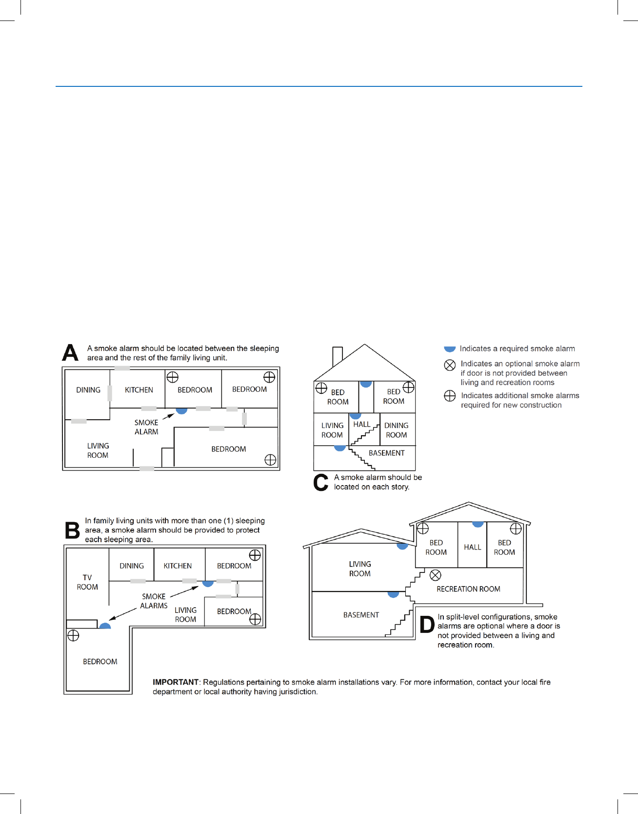
●Install a smoke detector outside each separate sleeping area, in the immediate vicinity of the bedrooms and on each
additional story of the family living unit, including basements (excludes crawl spaces and unnished attics).
Also install smoke detectors in the living room, dining room, bedrooms, kitchen, hallway(s), nished attics, furnace
room, utility/storage rooms and attached garages.
Smoke, Heat and Freeze Protection

Copyright © 2018 Nortek Security & Control
20
GC2.5 Wireless Security System | User Guide
Do Not Mount a Smoke Alarm Here
●Directly above a sink, cooker, stove, or oven
●Within 5 feet (1.5 m) of any cooking appliance
●Next to a door or window that would be affected by drafts (extractor fan or air vent)
●Outside
●In or below a cupboard
● Where air ow would be obstructed by curtains or furniture
●Where dirt or dust could collect and block the sensor
●Where it could be knocked, damaged, or inadvertently removed
Fire-warning equipment for residential occupancies are capable of protecting about 50% of the occupants in potentially
fatal res. Victims include the elderly, children, and the physically or mentally impaired. Victims include any persons who
cannot escape even when warned early enough that escape should be possible. For these people, other strategies such
as protection-in-place or assisted rescue or escape would be necessary.
●Studies show that Smoke/Heat/Freeze Alarms may not awaken all sleeping individuals. Individuals in the household
who are capable of assisting others are responsible for providing assistance to those who may not be awakened by
the audible alarm or those who may be incapable of safely evacuating the area unassisted.
● A battery-powered alarm must have the specic battery type installed, be in good condition, and be mounted
properly.
●The use of alcohol or drugs may also impair the ability to hear the audible alarm. For maximum protection, ensure
that an audible alarm is installed on every oor.
●Smoke/Heat Alarms only provide protection to the residence if smoke actually reaches the alarm. The Smoke/Heat
Alarm is not a substitute for an insurance policy. Home owners and renters should have adequate insurance to
protect their properties.
Emergency Action Plan
Establish and regularly practice a plan of escape with all members of your household in the event of re. The National Fire
Protection Association recommends the following steps:
1 Mount your detector or your interior or exterior sounders where they can be heard by all.
2 Determine two means of escape from each room. One path of escape should lead to the door that permits normal
exit from the building. The other should be an alternate escape (such as a window) should the path to a door be
impassable. Station an escape ladder at such windows if there is a long drop to the ground.
3 Sketch a oor plan of the building. Show windows, doors, stairs, and rooftops that can be used to escape. Indicate
escape routes for each room. Keep these routes free from obstructions and post copies of the escape routes in every
room.
4 Ensure that all bedroom doors are shut while you are asleep to prevent deadly smoke from entering while you
escape.
5 Try the door. If the door is hot, check your alternate escape route. If the door is cool, open it cautiously. Be prepared to
slam the door shut if smoke or heat rushes in.
6 When smoke is present, crawl on the ground. Do not walk upright, since smoke rises and may overcome you. Clearer
air is near the oor.
7 Escape quickly, but do not panic.
8 Establish a place outdoors, away from your house, where everyone can meet and then take steps to contact the
authorities and account for those missing. Choose someone to assure that nobody returns to the house — many die
going back.
Smoke, Heat and Freeze Protection
Copyright © 2018 Nortek Security & Control
21
GC2.5 Wireless Security System | User Guide
EMERGENCY FUNCTIONS
24-HOUR EMERGENCY BUTTONS
Three 24-hour emergency functions are available on the Control Panel:
●Panic
●Fire
●Emergency
You can activate emergency functions using the Control Panel, as well as wireless sensors, wireless keypads or portable
pendant devices such as the panic button remote.
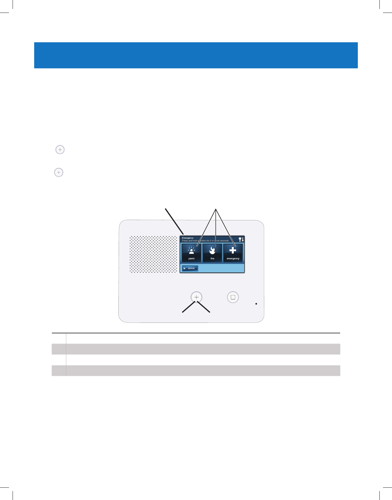
Tap the button to reveal the Emergency screen. This button does not trigger an alarm. During the installation, your
installer programmed the emergency buttons that are displayed on the Emergency screen. If, however, no emergency
functions are available, an information screen displays. To see which emergency functions are available on your system,
tap the button.
In the event of an emergency, press and hold the Emergency button for at least two (2) seconds to activate the alarm.
AIf emergency functions are available, the Emergency button is a solid white lighted button.
BTo display the Emergency screen, press the Emergency button.
CThe Emergency screen.
DThe Emergency screen displays the emergency options that are available on your system.
Panic
The Panic (or police) button sends an immediate panic report to the Central Station. During installation, the installer either
set the system to sound the siren when the button is pressed, or to not sound the siren, but to trigger a silent alarm.
Fire
The Fire button sends an immediate re report to the Central Station. The Control Panel sounds the re horn when the
button is pressed.
Emergency
The Emergency button sends an immediate report to the Central Station. The Control Panel sounds the siren when the
emergency button is pressed.
A
D
B
C
Copyright © 2018 Nortek Security & Control
22
GC2.5 Wireless Security System | User Guide
SYSTEM TROUBLE ALERTS
The system continually polls wired sensors, wireless
sensors and the Control Panel itself to ensure optimal
operating conditions at all times. If trouble is detected, the
system alerts you.
The system monitors the following conditions among
others:
●AC power to the Control Panel
●The telephone line (optional)
●The cell telephone connection (if used)
●The Control Panel’s backup battery
●The Sensor batteries
●Sensor supervisory status (if used)
●External sounder connection
●Sensor radio reception and sensor tampering
(sensor’s case opened) when disarmed
●Control Panel tampering (panel’s case opening) when
disarmed (optional)
●Communication to the Central Station. You have the
option to have any or all trouble conditions reported
to the Central Station. If a trouble condition exists,
service your system immediately to ensure no lapse in
service or protection.
TROUBLE ALERT ICON
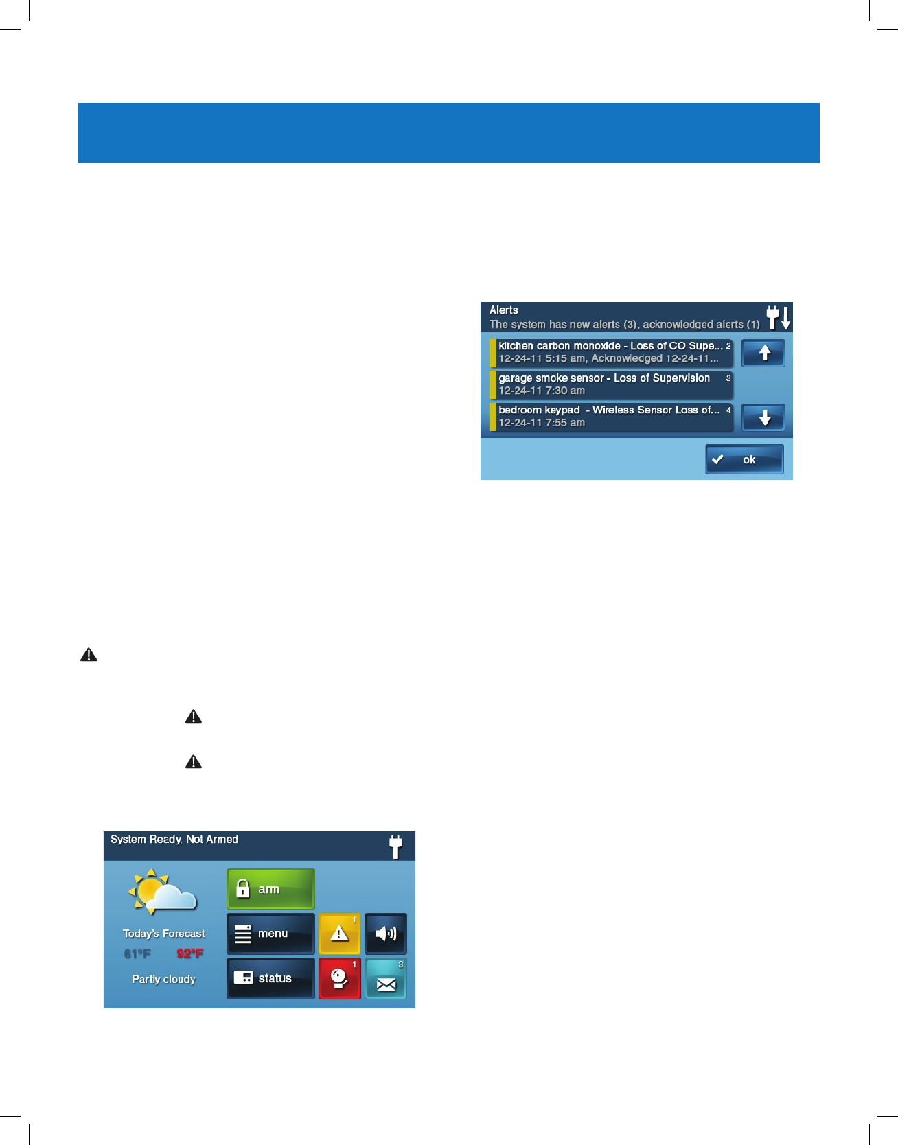
If the system detects trouble, it ashes the trouble Alert
icon on the Security screen and sounds 6 alert beeps
every minute. Scrolling text along the top of the display also
describes the trouble condition.
The trouble Alert icon displays a number in the upper
right corner that shows the number of current trouble alerts.
The trouble Alert icon ashes until the trouble alerts
are acknowledged, then it remains constantly lit until all the
troubles are corrected. When all troubles are corrected, the
icon disappears completely.
VIEW THE CURRENT TROUBLE ALERTS
1 To display all current trouble alerts, tap the Trouble
Alert icon.
2 View the listed trouble events. If there are more than
3 alerts, use the and arrows to scroll through the
list.
3 After viewing the trouble events, tap OK to
acknowledge. This action silences the alert beeps.
TROUBLE ALERT BEEP HOLD-OFF
During the installation, as an option, the system can be
programmed by your installer to suppress the trouble alert
sounder from 10 pm to 9 am. Any trouble alerts will still be
displayed and reported (if enabled), but the sounder does
not beep during nighttime hours. Some trouble conditions
may clear automatically while other trouble conditions may
require service to correct. If a trouble condition still exists
after 9 am, the sounder beeps to indicate trouble.
NOTE: Regardless of whether the trouble alert sounder
is suppressed or not, every trouble condition is always
displayed on the trouble alert list and recorded in the
system history event log.
Copyright © 2018 Nortek Security & Control
23
GC2.5 Wireless Security System | User Guide
SYSTEM STATUS ICONS
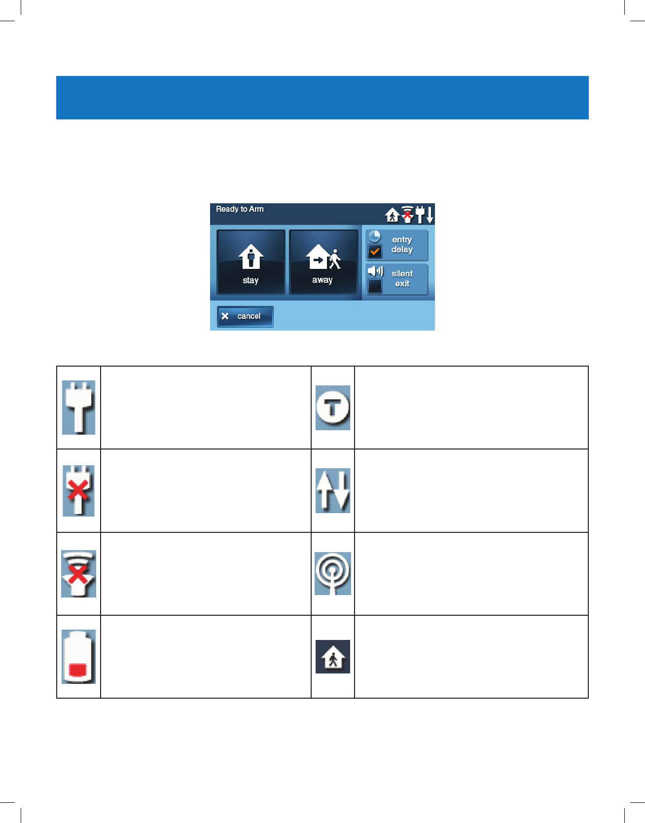
AC POWER ON
The AC Power icon shows the status of the
AC power to the Control Panel. A WHITE plug
appears when AC power is present.
TEST MODE
This icon displays when the system is in Walk Test
mode.
AC POWER OFF
The AC Power icon shows the status of the
AC power to the Control Panel. A RED “X”
appears over the WHITE plug when AC power
is absent.
TOUCH SCREEN KEYPAD TRAFFIC
An up arrow indicates the panel is sending
information to the touch screen keypad (if installed).
A down arrow indicates the touch screen keypad is
sending information to panel.
SOUNDER DISABLED
If the system’s internal sounder has been
lowered and external sounder has been
disabled by the installer for testing, the
sounder disabled icon appears. It also ashes
to indicate silent arming.
CELL RADIO
If the option GSM (Cellular) Radio Module is
installed, the Cell Radio icon appears while the
Control Panel is receiving Over-the-Air (OTA)
rmware updates.
LOW BACKUP BATTERY
If the Control Panel’s backup battery tests low,
the low backup battery icon appears.
INTERIOR SENSOR OPEN
If an interior sensor is open or a motion detector
has just been activated, this icon appears. As a
warning, the icon ashes during arming.
Copyright © 2018 Nortek Security & Control
24
GC2.5 Wireless Security System | User Guide
MESSAGING
Your security system supports receiving messages from
the Central Station. The messages can be about system
upgrades, additional services, special regional weather
alerts, etc. The messages can be sent for all system users
to read, or as condential messages that only the Master
User can read.
Messages can be tagged by the sender in the following
manner:
●Standard (blue message icon)
●Urgent (yellow message icon)
●Emergency Priority (red message icon)
Up to 31 text messages can be stored in the Control
Panel’s memory. You can review them through the Control
Panel’s display. Displayed messages are sorted in the
following manner:
●Type
●Date
●Alphabetically
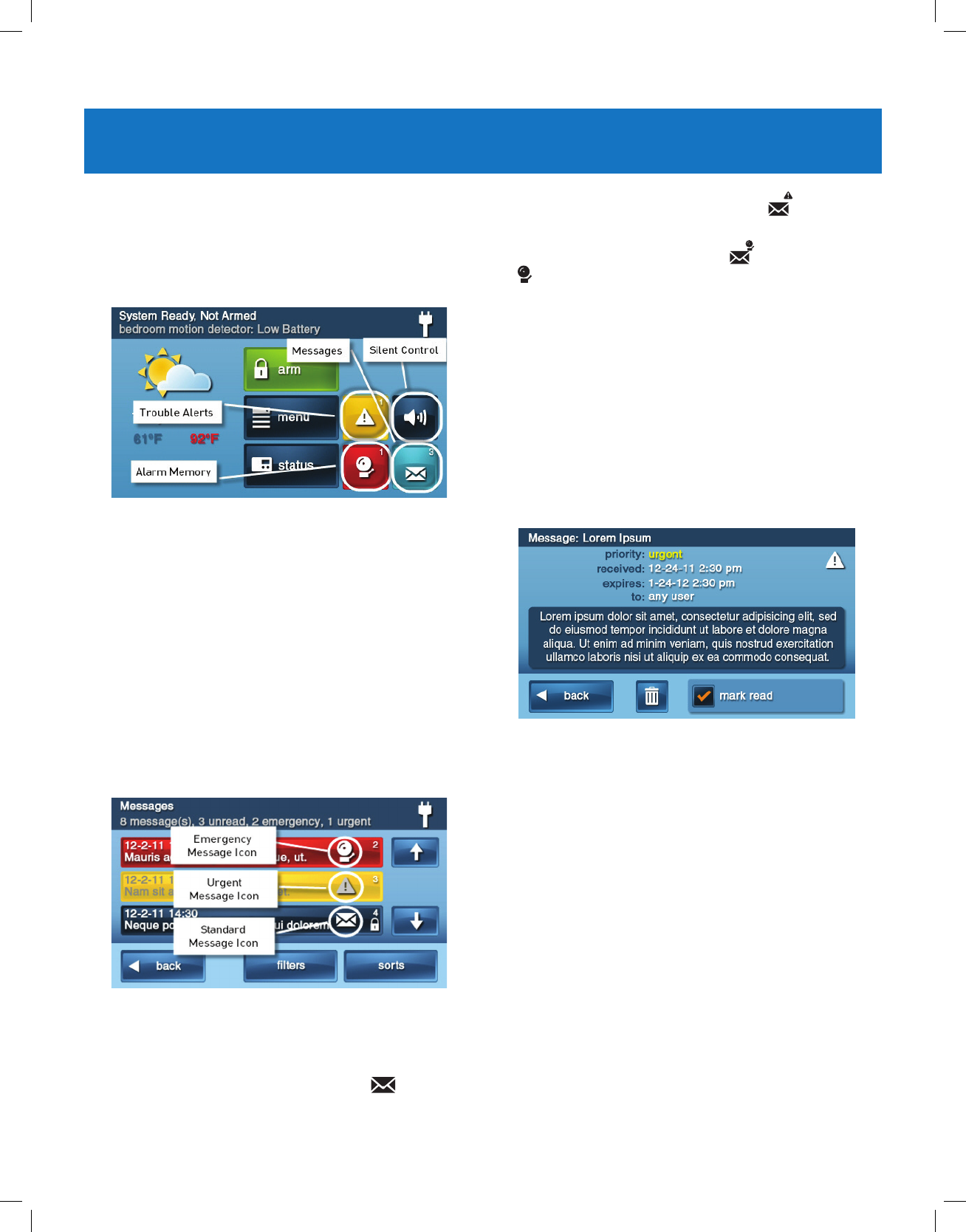
DISPLAYING MESSAGES
When a message is sent to the Control Panel, 3 beeps
sound and the message icon displays on the Security
screen. Standard messages display a blue message
icon with a number of unread messages in the upper right
corner. Urgent messages display a yellow message
icon with an attention symbol in the upper right corner.
Emergency messages display a red message icon with
the bell symbol in the upper right corner.
READING MESSAGES
When a message icon appears on your Home screen:
1 Tap the message icon button. The message list
displays. The status bar shows the number of
messages in memory, number of unread, and number
of priority messages. Unread messages display in
bold.
2 Use the or arrows to scroll through the message
list.
3 Tap the message line itself to read the message.
4 Tap Back to return to the message list, or tap Delete to
erase the message.
NOTE: If you check the Mark Read box, the message
remains on the message list, but it no longer displays
in bold.
5 When deleting a message, a conrmation screen
displays. Tap Delete Message, or to return to the
message, tap Cancel.
Copyright © 2018 Nortek Security & Control
25
GC2.5 Wireless Security System | User Guide
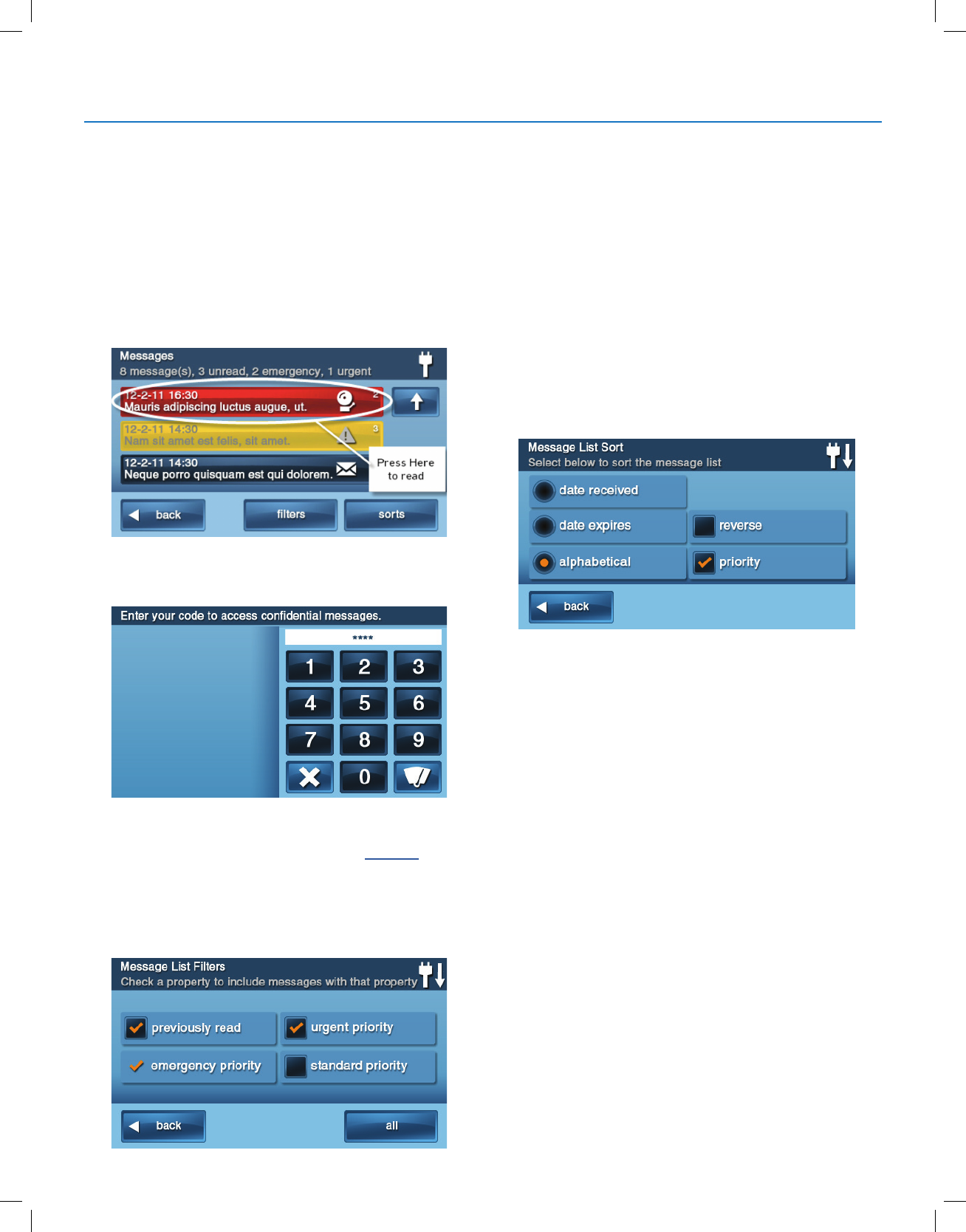
READING CONFIDENTIAL MESSAGES
NOTE: When a condential message is sent to the Control
Panel, only the Master User with the master user code can
read the message.
When a condential message appears, the Master User
should do the following:
1 Tap the message line on the message list. If the
message is a condential message, the Code Entry
screen appears.
2 Enter the master user code. Other user codes are not
accepted.
3 View the displayed message.
4 As detailed in "Reading Messages" on page 24, either
save or delete.
FILTERING MESSAGES
To select the type of messages that are displayed on the
message list, use the Message Filter screen.
1 To display the Message Filter screen, tap Filters.
2 Check or clear the boxes of the types of messages to
display. To check all types of messages, tap All. To
return to the message list, tap Back.
The lters will reset when the following occurs:
●You select All Types
●Your message reviewing is over
●The system displays the Security screen
SORTING MESSAGES
To select the order in which messages are displayed on the
message list, use the Message Sort screen.
1 To display the Message Sort screen, tap Sorts.
2 To sort the messages, pick from the following options:
●Date received
●Date expired
●Alphabetically
3 To reverse the display order, check the Reverse box.
4 To list urgent messages rst, check the Priority box.
5 To return to the message list, tap Back.
6 When the message reviewing session is over, the sort
options will reset.
Messaging
Copyright © 2018 Nortek Security & Control
26
GC2.5 Wireless Security System | User Guide
SYSTEM TOOLBOX
USER MANAGEMENT
The system installer has programmed a master user code
for your system. This code can be used to control the
system, as well as to assign and change the other 59 user
codes and access options. The master user code can also
access several system settings in the Toolbox.
NOTE: The other 59 user codes are restricted from
accessing settings in the Toolbox.
User Code Setup
IMPORTANT: The holder of the master user code is the
only user who has permission to set up other user codes.
To set up the user codes:
1 At the Home screen, tap Security.
2 At the Security screen, tap Menu.
3 At the Menu screen, tap Toolbox.
4 Enter the master user code to access the Toolbox
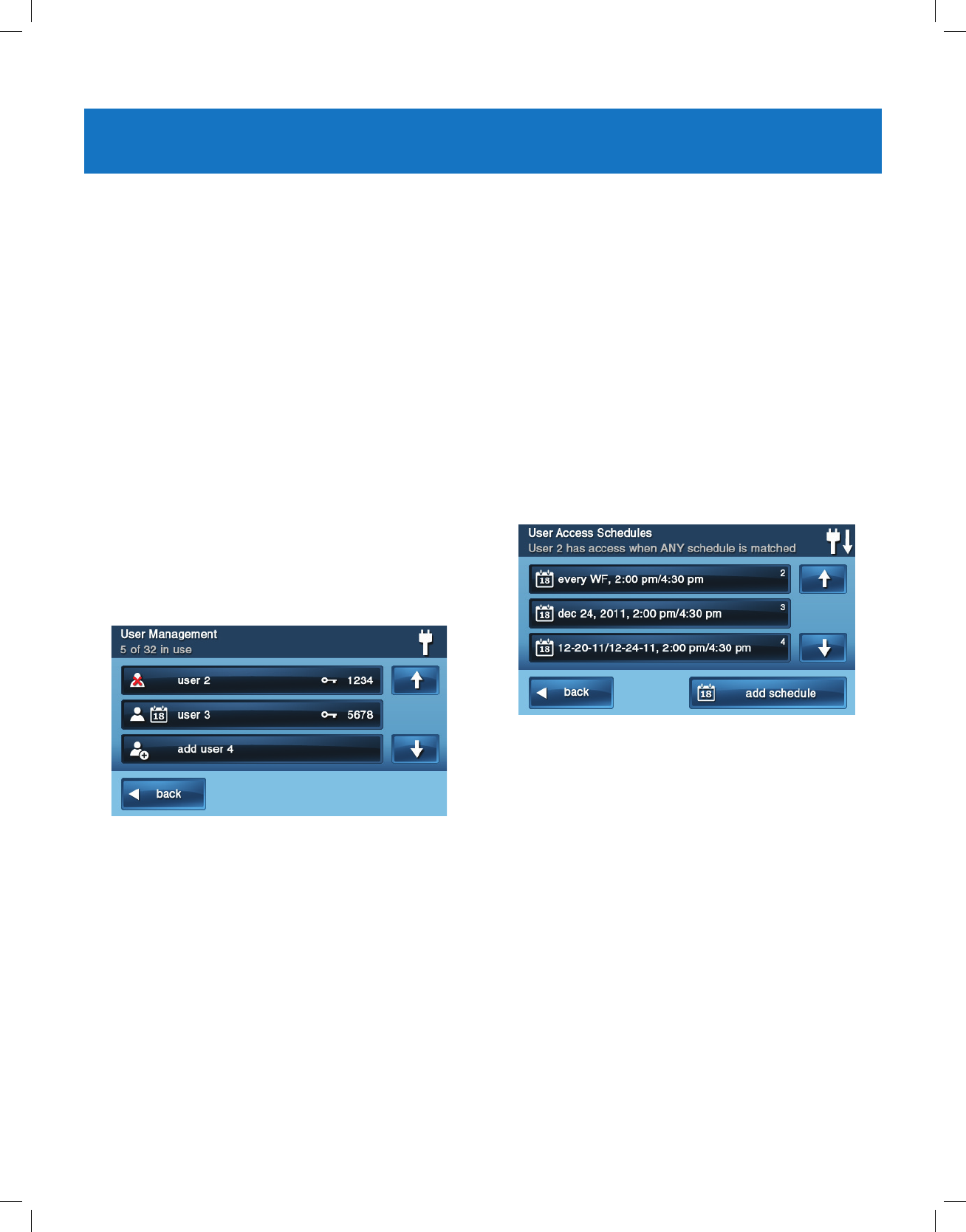
5 On the Toolbox (1 of 3) screen, tap User Management.
6 The Users Management screen displays 3 users at a
time. Use the and arrows to scroll through the list.
Adding a User Code
IMPORTANT: User codes 0000 and 0001 are not
permitted.
1 Tap one of the Add User buttons.
2 Enter a unique four (4)-digit code for the new
user code. Then tap OK.
3 Enter the code again to conrm it. Then tap OK.
4 At the Conrmation screen, tap OK to return to the
User Management screen.
User Code Validity
After the Conrmation screen appears and you click OK,
the user codes Access Option screen appears. Select one
of the three options to validate the user code:
●Select Always to set this user code to always be
valid. Tap Back.
●Select Never to set this user code to never be valid.
Tap Back.
●Select By Schedule to set this user code to be valid
only for selected days and/or times.
User Code Access Schedules
You can set up user codes with one or more Access
Schedules. Access Schedules limit access to your system
to people with user codes (such as maintenance personnel,
service, or cleaning personnel).
Adding/Editing User Access Schedules
1 If you selected By Schedule for the user code, the
Edit Schedules button appears.
2 To select or edit an existing user code Access
Schedule, tap Edit Schedules. You can also create a
new user schedule from the Edit Schedules screen.
3 The User Access Schedules screen displays all
current schedules for the user code.
4 To add a new schedule, tap Add Schedule or to edit a
schedule, tap an existing schedule.
5 You can select 1 of 3 Schedule types:
●Recurring. Recurring applies to the days of the week
and time period that this user code is valid.
●Date. Date applies to a single specic date and time
period that this user code is valid.
●Date Range. Date Range denes a starting date,
an ending date, and time period during which this
user code is valid.
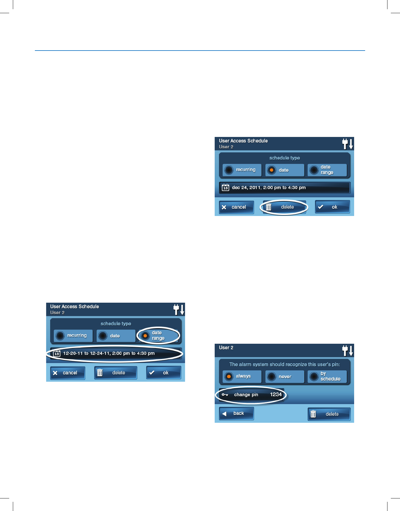
Copyright © 2018 Nortek Security & Control
27
GC2.5 Wireless Security System | User Guide
Recurring User Access Schedules
You can dene up to 7 Access Schedules for user codes
with and Access Option of Always.
1 For the schedule type, select Always.
2 To view the User Access Schedule screen, tap the
calendar button.
3 Select the day(s) of the week that this user code will be
valid with the check boxes.
4 Tap the left and right time buttons to set the starting
and ending times that this user code will be valid on the
selected days of the week.
5 Tap OK to accept the schedule, or Cancel to return to
the Schedule Type screen.
Date User Access Schedule
1 For the schedule type, select Date.
2 To view the User Access Schedule screen, tap the
calendar button.
3 To set the only month, day, and year that this user code
is valid, tap the date button.
4 Tap the left and right time buttons to set the start and
end times that this user code is valid on that date.
5 Tap OK to accept the schedule, or Cancel to return to
the Schedule Type screen.
Date Range User Access Schedule
1 For Schedule type, select Date Range.
2 To view the User Access Schedule screen, tap the
calendar button.
3 Tap the rst day button to set the month, day, and year
that this user code will rst become valid.
4 Tap the last day button to set the month, day, and year
that this user code will last be valid.
5 Tap the left and right time buttons to set the starting
and ending times that this user code is valid during the
date range.
6 To accept the schedule, tap OK or Cancel to return to
the Schedule Type screen.
Deleting User Access Schedule
1 On the User Management screen, select a user code
that has a calendar schedule icon.
2 Tap the Edit Schedules button.
3 On the User Access Schedule screen, select the
schedule to delete.
4 On the Schedule Type screen tap Delete.
5 A conrmation screen appears to verify that you want
to delete the User Access Schedule. If Ok, tap Delete
Schedule or tap Cancel to return to the User Access
Schedule screen.
6 6 A second screen conrms that the schedule was
deleted. Tap OK.
User Codes
Changing a User Code
1 At the User Management screen, tap the User button
to change the user code.
2 Ensure that the current user code appears. Then tap
Change Pin.
3 Enter a new four (4)-digit user code to use as the PIN.
Then tap OK.
System Toolbox
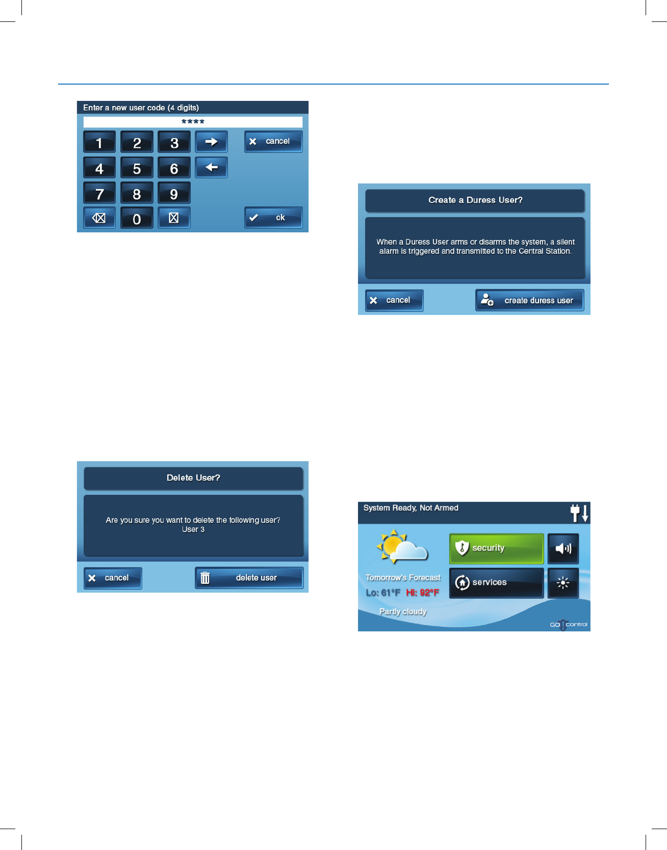
Copyright © 2018 Nortek Security & Control
28
GC2.5 Wireless Security System | User Guide
4 To conrm the user code, enter then new code again.
Tap OK.
5 A conrmation screen appears, showing that the
user code was changed. Tap OK.
Deleting a User Code
1 To delete a user code from the User Management
screen, tap the User button.
2 Tap Delete.
3 A conrmation screen appears to verify that you want
to delete the user code. If Ok, tap Delete User or tap
Cancel to return to the user codes Access Option
screen.
4 A conrmation screen appears displaying the user code
that was deleted. Tap OK.
TIP: You can change the master user code, but you cannot
delete it.
Duress User Code Setup
The Duress Code (User Code #8) initiates a silent alarm
for help by secretly sending a Duress report to the Central
Station.
Use the duress code when someone is forcing you to
operate your security system against your will. When you
use the duress code, a silent report is immediately sent to
the Central Station and they will dispatch help.
Setting the Duress User Code
1 On the User Management screen, tap the User 8
(Duress) button.
2 A conrmation screen appears: Tap Create Duress
User.
3 Enter a four (4)-digit code to use as the new duress
code. Then tap OK.
4 To conrm the duress code, enter the code again and
tap OK.
5 A conrmation screen appears. Tap OK.
6 The User 8 edit screen appears. To return to the User
Management screen, tap Back.
Secret Duress Button
On the Home screen, the system logo always appears in
the lower right corner. The system logo is the secret duress
button.
While Armed
With the system armed, tapping the logo displays the
standard disarm code entry screen. Use a valid user code
or a duress user code to disarm the system. The system
disarms normally, but a silent duress report is sent to the
Central Station and they will dispatch help. If supported
by the 2GIG Alarm dealer, the left side of this screen also
displays contact information for the alarm dealer or Central
Station.
System Toolbox
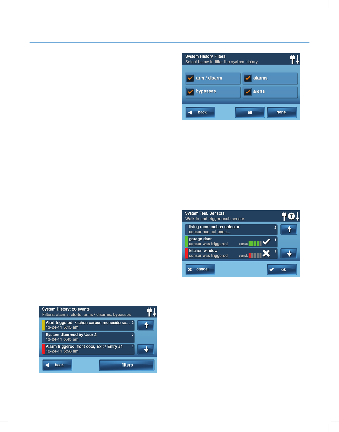
Copyright © 2018 Nortek Security & Control
29
GC2.5 Wireless Security System | User Guide
While Disarmed
You can also use the secret duress button while the system
is disarmed. Tapping the system logo reveals the Enter
Code screen. Enter the duress code to send a silent duress
report to the Central Station and they will dispatch help.
The system remains disarmed. If supported by the 2GIG
Alarm dealer, the left side of this screen also displays
contact information for the alarm dealer or Central Station.
SYSTEM HISTORY
The Control Panel keeps a log of system events in the
order in which they occur. Each event is marked with the
date and time that the event occurred.
To make reading the log easier, the system history display
can be ltered to show selected events only. The events
that can be ltered for the system history log display are:
●Armor disarm of the system
●Bypasses of sensors (force bypasses and manual
bypasses)
●Alarms (alarms are displayed with a red stripe)
●Alerts (alerts are displayed with a yellow stripe)
Some system events always display regardless of the lters
selected. These events include:
●Walk test started or terminated
●Programming mode started or terminated
To view the system history log:
1 At the Home screen, tap Security.
2 At the Security screen, tap Menu.
3 On the Menu screen, tap Toolbox.
4 Enter a valid user code to access the toolbox.
5 At the Toolbox (1 of 3) screen, tap System History. The
log of system events appears. Use the and arrows
to scroll through the log.
6 To choose the events to display, tap Filters.
7 Select the events to display with the check boxes. Tap
All to select all the check boxes, or None to clear all
the check boxes.
8 Tap OK when nished.
SYSTEM TEST
Even though your security system is self-monitoring, it
is still important to regularly test the system manually.
The System Test is used to test each of the sensors in
the system. The master user code is required to test the
system. While the system is in test mode, a “T” icon blinks
on the upper right of the display.
IMPORTANT: Test your Security System weekly to ensure
continued protection and proper system operation.
To test the system:
1 At the Home screen, tap Security.
2 At the Security screen, tap Menu.
3 At the Menu screen, tap Toolbox.
4 To access the system test, enter the master user code.
5 At the Toolbox (1 of 3) screen, tap System Test.
System Toolbox
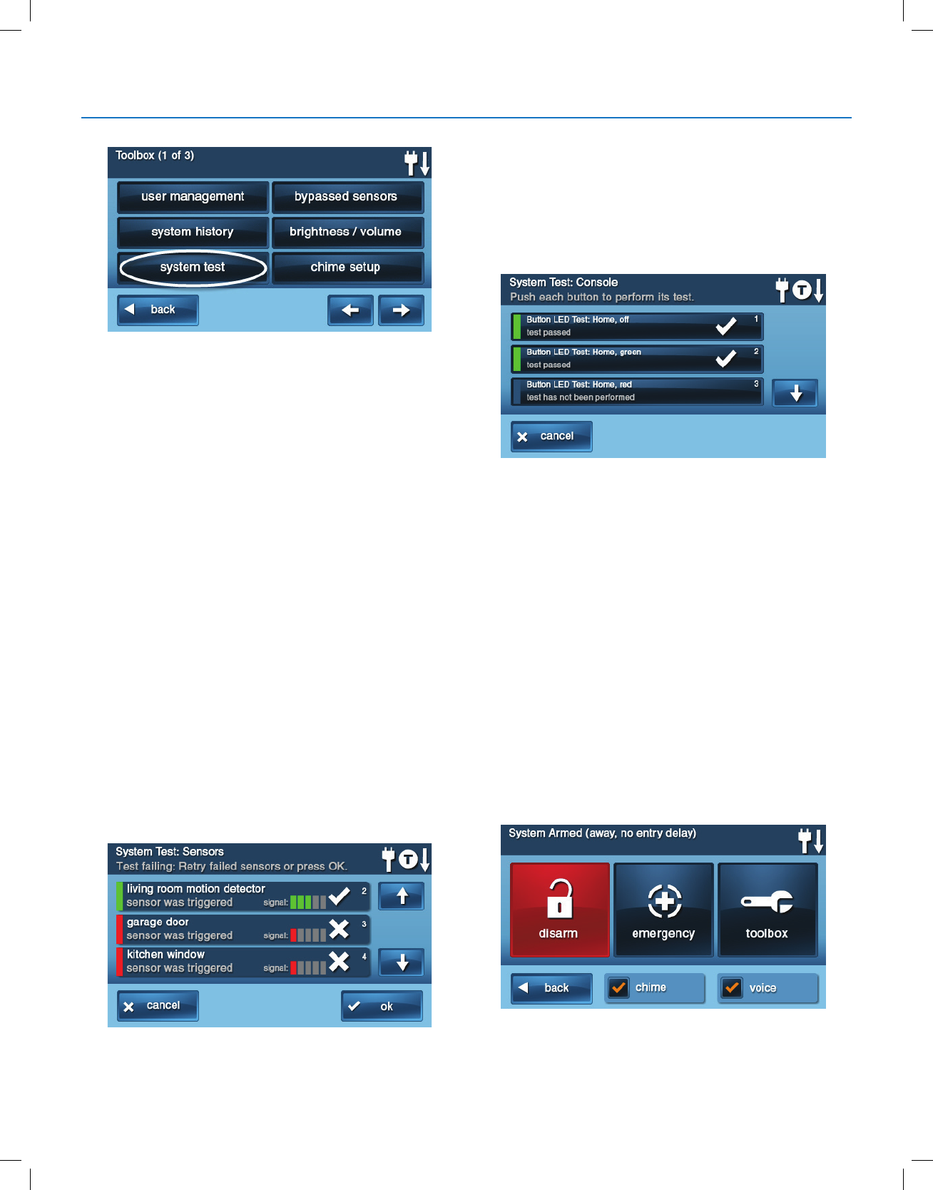
Copyright © 2018 Nortek Security & Control
30
GC2.5 Wireless Security System | User Guide
Sensor Test
When each sensor is tested, the Control Panel does the
following:
●Beep sand announces the sensor’s name
●Displays green bar lights by the sensor name
●Displays green signal bars to show the strength of that
sensor’s wireless signal.
NOTE: Start and stop test reports are sent to the Central
Station.
1 At the System Test: Console screen, a list of sensors
appears. Use the and arrows to scroll through the
list.
2 Go to each sensor listed, and trigger it.
●For door or window sensors, open and close the
door or window.
●For motion detectors, stay out of the protected area
for ve (5) minutes, then walk through the area.
●For portable sensors and wireless keypads, tap a
button.
●For smoke, CO, or glass break detectors, tap the
detector’s test button.
TIP: When a red bar is displayed for a sensor, the test has
failed.
3 When all sensors have been tested, tap OK. Then
continue with the Panel Test.
Panel Test
The panel test checks the Control Panel’s indicators and
sounder.
1 At the System Test: Console screen, a list of tests
to perform on the panel appears. Use the and
arrows to scroll through the list.
2 Tap each button in the list. Then tap Yes or No to
respond to the test question.
3 After answering all of the questions, tap OK.
4 At the System Test Successful screen, tap OK.
CHIME SETUP
On doors and windows monitored by sensors, the system
can sound a chime to announce that the door or window
was opened. Sensors can also be set to have the Control
Panel say the name of the opening.
TIP: The chime and voice announcements only sound
while the system is disarmed.
At the time of installation, the installer programs each
sensor’s chime option. The person with the master
user code can change the chime options for each sensor to
further customize the system as desired.
TIP: As a global system option, the chimes for all the
system’s sensors can be turned on or off using the Chime
check box on the Menu screen.
System Toolbox
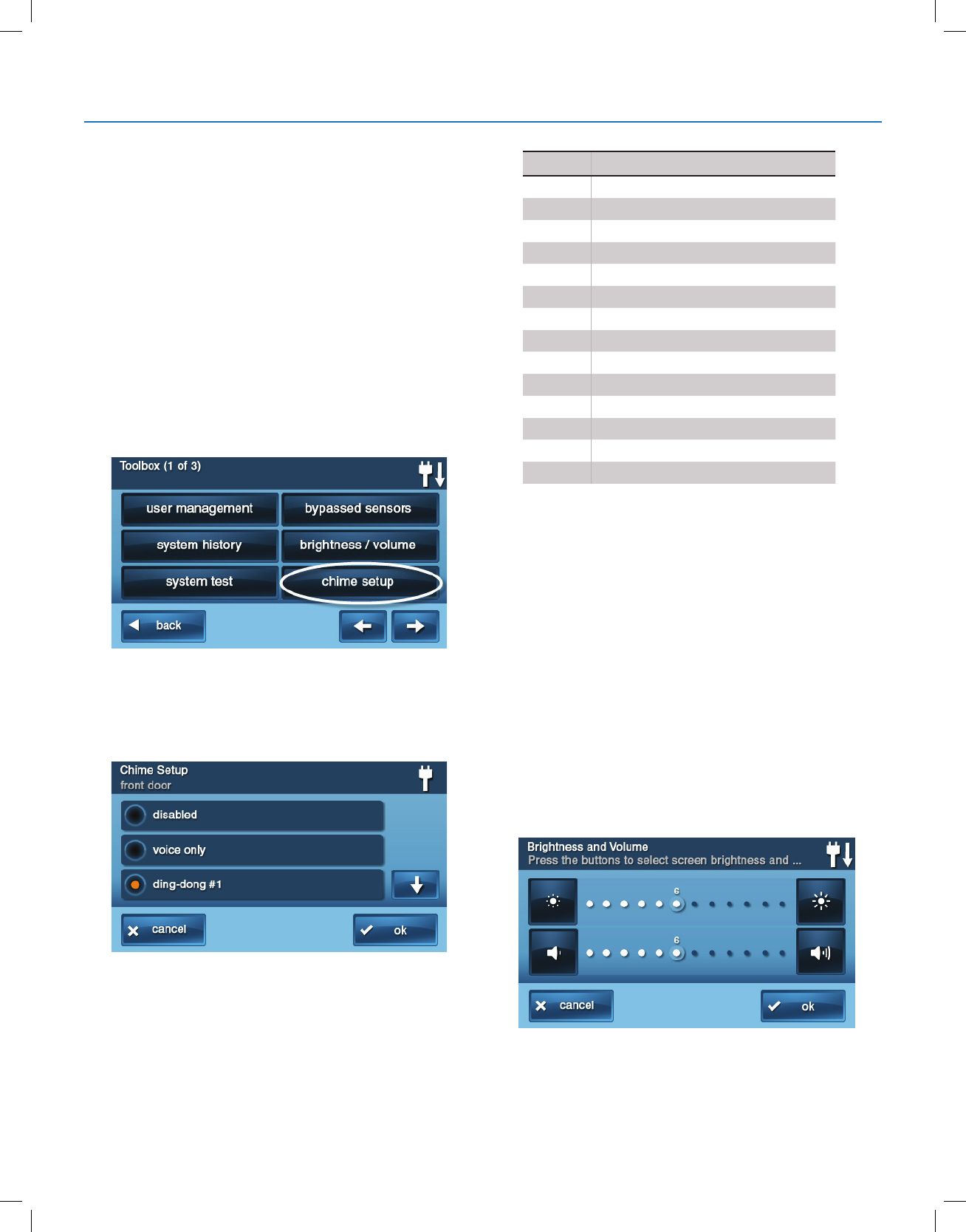
Copyright © 2018 Nortek Security & Control
31
GC2.5 Wireless Security System | User Guide
To setup the chime options individually for each sensor:
1 At the Home screen, tap Security.
2 At the Security screen, tap Menu.
NOTE: Select or clear the Chime and Voice check boxes
to turn the system chimes and voice announcements ON or
OFF (except for alarm voice messages).
3 At the Menu screen, tap Toolbox.
4 Enter the master user code to gain access to the
Toolbox.
5 At the Toolbox (1 of 3) screen, tap Chime Setup. The
Chime Setup screen displays each of the installed
sensors that can chime and the option currently set for
the sensor.
To change the sensor’s chime options, tap the sensor
button.
TIP: There are 14 chime options for each sensor.
6 Check the option that you want for the sensor, then tap
OK.
7 When you are nished, tap Back.
ADJUSTING THE BRIGHTNESS/VOLUME
You can adjust the brightness of the Control Panel’s display
and the volume of the system’s speaker that is best suited
to your installed system.
To set the brightness and volume:
1 At the Home screen, tap Security.
2 At the Security screen, tap Menu.
3 At the Menu screen, tap Toolbox.
4 Enter the master user code to gain access to the
Toolbox.
Chime Option
1Disabled
2Voice Only
3Ding-dong #1
4Ding-dong with Voice #1
5Ding-dong #2
6Ding-dong with Voice #2
7Ding-dong #3
8Ding-dong with Voice #3
9Ding-ding
10 Ding-ding with Voice
11 Chime #1
12 Chime with Voice #1
13 Chime #2
14 Chime with Voice #2
System Toolbox
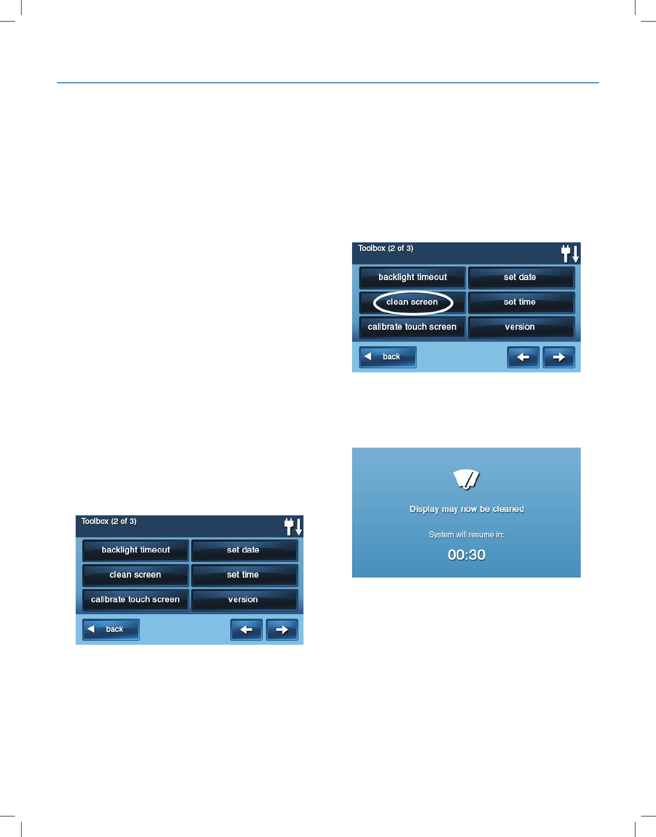
Copyright © 2018 Nortek Security & Control
32
GC2.5 Wireless Security System | User Guide
5 At the Toolbox (1 of 3) screen tap Brightness/Volume.
You can set the brightness using the top bar. Adjust the
level from 1 to 12 using the buttons on each end of the
bar.
6 You can set the speaker volume for the chimes and
announcements on the bottom bar. Adjust the level
from 1 to 12 using the buttons on each end of the bar.
NOTE: The volume setting does not effect the alarm
sounder volume.
7 When you are nished, tap OK.
ADJUSTING THE BACKLIGHT TIMEOUT
The backlight timeout sets the length of time that the
display stays lit after use. You can adjust the backlight to
30 seconds, 1, 2, 5, or 10 minutes, or to always (to light the
display at all times).
NOTE: To conserve the Control Panel’s backup battery,
during an AC power failure, the display goes dark after 30
seconds regardless of this setting.
To set the display backlight time:
1 At the Home screen, tap Security.
2 At the Security screen, tap Menu.
3 At the Menu screen, tap Toolbox.
4 Enter a valid user code to gain access to the Toolbox.
5 At the Toolbox (1 of 3) screen, tap the arrow.
6 At the Toolbox (2 of 3) screen, tap Backlight Time-out.
7 Choose one of the display backlight times and tap OK.
CLEANING THE TOUCH SCREEN
There is a special option for the Control Panel that enables
you to clean the touch screen display. The option disables
the touch screen for 30 seconds so the display can be
cleaned with a dry, soft cloth.
To disable the touch screen for cleaning:
1 At the Home screen, tap Security.
2 At the Security screen, tap Menu.
3 At the Menu screen, tap Toolbox.
4 Enter a valid user code to gain access to the Toolbox.
5 At the Toolbox (1 of 3) screen, tap the arrow.
6 At the Toolbox (2 of 3) screen, tap clean screen.
NOTE: The Display Cleaning screen appears for 30
seconds. It shows the time remaining. The touch screen is
locked during this time. When the timer expires, the system
returns to the Toolbox screen.
SET DATE AND TIME
The Control Panel has a built-in clock and calendar. The
Home screen displays the time and date. The time and
date are also used for the system history and event logs
that store data on system events.
NOTE: During installation, your installer can set the
system to automatically adjust for daylight saving time if it’s
observed in your location.
NOTE: The time and date are automatically set through the
cellular radio by the Central Station if your Control Panel
has a cellular radio installed.
System Toolbox
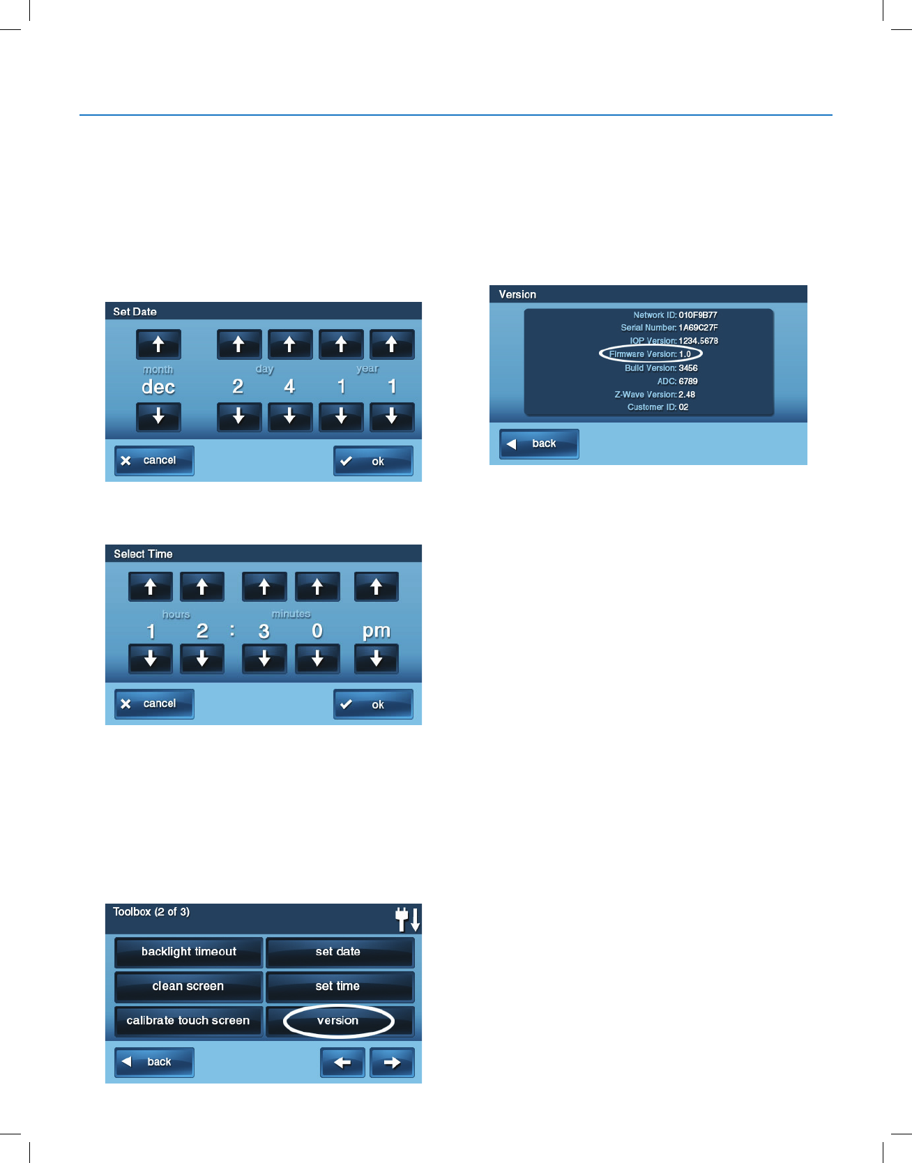
Copyright © 2018 Nortek Security & Control
33
GC2.5 Wireless Security System | User Guide
To set the date and time:
1 At the Home screen, tap Security.
2 At the Security screen, tap Menu.
3 At the Menu screen, tap Toolbox.
4 At the Toolbox (1 of 3) screen, tap the arrow.
5 At the Toolbox (2 of 3) screen, tap Set Date or Set
Time.
6 Use the and arrows to set the current date or
time. Tap OK.
7 A conrmation screen showing the date and time set
appears. Tap OK.
DISPLAY FIRMWARE VERSION
To troubleshoot your system, you can check the rmware
version that has been installed.
To display the rmware version:
1 At the Home screen, tap Security.
2 At the Security screen, tap Menu.
3 At the Menu screen, tap Toolbox.
4 At the Toolbox (1 of 3) screen, tap the arrow.
5 At the Toolbox (2 of 3) screen, tap Version.
6 When nished, tap Back.
DEALER INFO SCREEN AND CALL BACK
BUTTON
Your 2GIG Alarm Dealer may congure the
Enter Your Code screen to display contact information for
your 2GIG Alarm Dealer or the Central Station.
Accessing the Dealer Info Screen
To access the Dealer Info screen:
1 At the Home screen, tap the system logo.
2 At the Enter Your Code screen, enter the four (4)-digit
master user code.
3 The left side of the Enter Your Code screen reveals
contact information for your 2GIG Alarm Dealer or the
Central Station.
Requesting a Service Call Back
To request a service call back:
1 At the Enter Your Code screen, a call back button
appears at the bottom or the screen.
2 Tap the Call Back button to transmit a report to your
alarm dealer or the Central Station.
When the report is received by the 2GIG Alarm Dealer
or Central Station, you will receive a call back in
accordance with the terms of your dealer’s service
agreement. For additional information about call backs,
consult your 2GIG Alarm Dealer.
System Toolbox

Copyright © 2018 Nortek Security & Control
34
GC2.5 Wireless Security System | User Guide
INSTALLER PROGRAMMED OPTIONS
The installer can program different options to customize
the installation. The options listed below show the default
settings and a check box or area to denote custom settings.
Siren Run Time
If there is a burglary, panic (police), or emergency alarm,
the Control Panel sounds the siren for a preset time. After
the time expires, the siren will stop sounding. (Auxiliary
alarms run for an unlimited time.)
Four Minutes is the default, or the following:
8 Minutes
12 Minutes
16 Minutes
Unlimited
Sensor Trigger Limit
The system limits the number of times a sensor can re-
trigger an alarm while the system is armed. The setting is 1
to 6 times per sensor, per arming period.
Two Triggers is the default, or the following:
1 Trigger
3 Triggers
4 Triggers
5 Triggers
6 Triggers
Fire Horn Run Time
If there is a re or carbon monoxide alarm, the Control
Panel sounds the re alarm horn for a preset time. After the
time expires, the re alarm horn will stop sounding.
Four Minutes is the default, or the following:
8 Minutes
12 Minutes
16 Minutes
Unlimited
Exit Delay
The Exit Delay begins immediately after arming the system.
The delay gives you time to leave through the designated
exit/entry door without setting off the alarm. During the Exit
Delay beeps sound, and faster beeps sound during the last
10 seconds.
NOTE: Arming remotely does not start an Exit Delay.
●60 Seconds is the default, or ________ For ________
Door.
Entry Delay
The Entry Delay begins when the designated entry/exit
door is opened while the system is armed. The delay gives
you time to disarm the system before triggering the alarm.
You must enter a valid user code on the Control Panel
or Wireless Keypad before the Entry Delay time expires.
During the Entry Delay, beeps sound to remind you to
disarm the system.
The system supports two different Entry Delays:
●Entry Delay #1 is for your primary entrance door
●30 Seconds is the default, or _________
Entry Delay #2 is for a secondary entrance (such as a
garage door) and is usually set longer to give you time to
get to the keypad and disarm the system.
45 Seconds is the default, or _________ For ________
Door
24-Hour Emergency Functions
The system can be congured to display three 24-hour
emergency buttons on the Control Panel: Panic, Fire, and
Emergency. The installer can set which emergency buttons
on the Control Panel are active.
Panic (Audible)
Panic (Silent)
Fire
Emergency
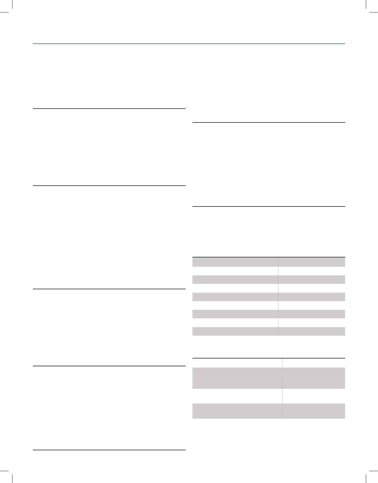
Copyright © 2018 Nortek Security & Control
35
GC2.5 Wireless Security System | User Guide
Quick Arming
Quick Arming allows you to arm your system without having
to enter a user code. When you tap the Stay or Away
button, the system will start to arm without requesting a
user code.
●Off
●On
Quick Bypass
Normally sensors that are open at the time the system
is armed will require force bypassing by entering your
user code. The system can be set so a user code is not
required to bypass open sensors when the system is
armed.
●Off
●On
Quick Exit
The Quick Exit option allows you to start the Exit Delay
while the system is armed. This allows you to leave the
premises without having to disarm and rearm the system.
When the Quick Exit option is on, a Quick Exit button will
display on the Security screen. Tap the button to start the
Exit Delay.
After Quick Exit, the system will fully re-arm in the mode
that it was in before (Stay or Away mode).
●Off
●On
Auto Un-bypass
Normally, sensors manually bypassed with the User
Toolbox will automatically have their bypasses removed
when the system is disarmed. The system can be set
so sensors that have been manually bypassed will stay
bypassed until the bypass is manually removed.
●Off
●On
Auto Stay
The Auto Stay option will change the arming mode if no
one exits after arming the system in Away mode. When the
system is armed in the Away mode the Exit Delay will begin.
With the Auto Stay option on, if a designated exit/entry door
does not open and close during the Exit Delay, the system
will arm in the Stay mode instead of the Away mode.
●Off
●On
Key Fob Sound
The system can be set so when it is armed or disarmed by
a wireless key fob, a beep will sound through the internal
and external sounders to indicate that the key fob’s signal
was received. This helps in installations where the Control
Panel is not visible or there are no other system status
indications at the key fob’s location.
●Off
●On
Key Fob Disarm After Sound
The system can be set so that when it is disarmed with
a wireless key fob after an alarm has occurred, a special
series of beeps will sound through the internal and external
sounders. This option serves as an alert to warn you to
approach the premises with caution as an intruder may still
be present.
●Off
●On
Key Fob Options
The installer selects which options are enabled for each
key fob (1-8) used with the system. Refer to the table below
for the options selected for your key fobs:
Key Fob Arming Bypass Options
Option 1 2 3 4 5 6 7 8
Arm without Exit Delay
Allow key fob disarming
Enable key fob auxiliary key
Auxiliary Alarm
Audible Alarm
Silent Panic Alarm
Fire Alarm
Emergency Keys Disabled
Option All Key Pads
Auto-bypass all open perimeter
sensors and un-bypass a sensor if
closed while the system is armed
Auto-bypass open perimeter sensors
permanently while armed
Allow key fob arming only when all
perimeter sensors are closed
System Toolbox
Copyright © 2018 Nortek Security & Control
36
GC2.5 Wireless Security System | User Guide
Wireless Keypad Emergency Keys
Each standard wireless keypad has Fire and Police
emergency buttons that can be enabled or disabled for
each keypad. Refer to the table below for options set for
your keypads:
Exit Delay Restart
The Exit Delay Restart option will extend the Exit Delay one
time if you need to re-enter the premises. When the system
is armed in the Away mode or Stay mode, the Exit Delay
gives you time to leave without setting off the alarm. With
the Exit Delay Restart option, re-entering the premises after
you have left, but before the Exit Delay timer expires, will
restart the Exit Delay timer, giving you the full length of time
to leave again. The restart option only works once, each
time the system is armed.
●Off
●On
Cancel Display
A “cancel” message will be sent to the Central Station if the
system is disarmed within a preset period of time after an
alarm is triggered. The system can be set to display that a
cancel report was sent, or for higher security, the system
can be set not to display the cancel message.
●Off
●On
Cancel Time
To limit responses to false alarms, a “cancel” message will
be sent to the Central Station if the system is disarmed
within a preset period of time after an alarm is triggered.
The alarm report is always sent, but it will be followed by
a cancel report if you disarm the system within the preset
time.
This option helps the Central Station to determine whether
you accidentally caused the alarm or if the alarm was
caused by an intruder. It also lets the Central Station know
that you have returned to the premises. Even if a cancel
message is sent, the Central Station will verify the alarm
and possibly dispatch help. The cancel message may be
processed by the Central Station at a later time depending
on system programming.
●Five Minutes is the default, or _______ Minutes
Dialer Delay
If an alarm occurs, the system will delay dialing for a short
time to allow you to disarm the system in case the alarm
was accidentally tripped. The dialer delay reduces nuisance
trafc to the Central Station and can prevent receiving nes
that many cities impose when police respond to a false
alarm. Your installer also can program the system for no
dialer delay.
NOTE: The dialer delay is also known as the abort window.
It gives you time to disarm, but doesn’t delay the siren from
sounding. Disarming during the abort window can display a
cancel message depending on the Cancel Display setting
(see "Cancel Display").
●30 Seconds is the default, or ______ Seconds.
2-Way Voice
The system can connect with a Central Station operator
so they can converse with people on the premises after an
alarm. The 2-way voice option allows communication to
and from the Control Panel and the Central Station. 2-way
voice communications will occur after the system has made
its alarm report. Your installer sets which sensors can
trigger the 2-way voice option.
●Off
●On
Option 1 2 3 4
Emergency Keys Enabled
Emergency Keys Disabled
System Toolbox

Copyright © 2018 Nortek Security & Control
37
GC2.5 Wireless Security System | User Guide
INSTALLER SPECIFIC INFORMATION
User Codes
Master User
User 2
User 3
User 4
User 5
User 6
User 7
User 8
User 9
User 10
User 11
User 12
User 13
User14
User 15
User 16
User 17
User 18
User 19
User 20
User 21
User 22
User 23
User 24
User 25
User 26
User 27
User 28
User 29
User 30
User 31
User 32
User 33
User 34
User 35
User 36
User 37
User 38
User 39
User 40
User 41
User 42
User 43
User 44
User 45
User 46
User 47
User 48
User 49
User 50
User 51
User 52
User 53
User 54
User 55
User 56
User 57
User 58
User 59
User 60
IMPORTANT: If you have logged user codes here to
maintain security, keep this guide in a secure location!

Copyright © 2018 Nortek Security & Control
38
GC2.5 Wireless Security System | User Guide
Zones
Zones Wireless Protection Zones (1-48)
1
2
3
4
5
6
7
8
9
10
11
12
13
14
15
16
17
18
19
20
21
22
23
24
25
26
27
28
29
30
31
32
33
34
35
36
37
37
39
40
41
42
43
44
45
46
47
48
Zones Hardwired Zone (49)
49
Keyfobs (51-58)
51
52
53
54
55
56
57
58
Keypads (59-62)
59
60
61
62
Wireless Protection Zones (63-74)
63
64
65
66
67
68
69
70
71
72
73
74
Duress (92)
92
Fire (95)
95
Medical (96)
96
Police Panic (99)
99
Installer Specific Information

Copyright © 2018 Nortek Security & Control
39
GC2.5 Wireless Security System | User Guide
SERVICE INFORMATION
Your local Alarm dealer is the person best qualied to service your alarm system. Be sure to set up a routine service
schedule with your local Alarm installer.

Copyright © 2018 Nortek Security & Control
40
GC2.5 Wireless Security System | User Guide
REGULATORY INFORMATION
Wireless Product Notice
Radio controls provide a reliable communications link and ll an important need in portable wireless signaling; however,
there are some limitations which must be observed.
For U.S. installations only: The radios are required to comply with FCC Rules and Regulations as Part 15 devices. As
such, they have limited transmitter power and therefore limited range.
A receiver cannot respond to more than one transmitted signal at a time and may be blocked by radio signals that occur
on or near their operating frequencies, regardless of code settings.
● Changes or modications to the device may void FCC compliance.
●Infrequently used radio links should be tested regularly to protect against undetected interference or fault.
●A general knowledge of radio and its vagaries should be gained prior to acting as a wholesale distributor or dealer,
and these facts should be communicated to the end users.
FCC Notice
This equipment generates and uses radio frequency energy and if not installed and used properly, that is, in strict
accordance with the manufacturer’s instructions, may cause interference to radio and television reception. It has been
type tested and found to comply with the limits for a Class B computing device in accordance with Part
15 of FCC Rules, which are designed to provide reasonable protection against such interference in a residential
installation. However, there is no guarantee that interference will not occur in a particular installation. If this equipment
does cause interference to radio or television reception, which can be determined by turning the equipment off and on, the
user is encouraged to try to correct the interference by one or more of the following measures:
●Relocate,the Console away from the TV/radio receiver.
●Plug the Console into a different wall outlet so that the Console is on a different branch circuit.
●Reorient the TV/radio antenna.
●If necessary, the user should consult the dealer or an experienced radio/television technician for additional
suggestions.

Copyright © 2018 Nortek Security & Control
41
GC2.5 Wireless Security System | User Guide
IMPORTANT NOTICE
ALARM SYSTEM LIMITATIONS
This security system can not offer guaranteed protection against burglary, re, or other emergencies. Any alarm system,
whether commercial or residential, is subject to compromise or failure to warn for a variety of reasons. For example:
●Intruders may gain access through unprotected openings or have the technical sophistication to bypass an alarm
sensor or disconnect an alarm warning device.
●Intrusion detectors (sensors) do not work without power. Battery operated devices do not work without batteries, with
dead batteries, or if the batteries are not put in properly. Devices powered solely by AC do not work if their AC power
supply is cut off for any reason, however briey.
● Signals sent by wireless sensors may be blocked or reected by metal before they reach the alarm Control Panel,
even if the signal path has been recently checked during a weekly test. Blockage can occur if a metal object has
been moved into the sensor’s signal path.
●A user may not be able to reach a panic or emergency button quickly enough.
● Even if the system responds to the emergency as intended, however, occupants may have insufcient time to protect
themselves from the emergency situation. In the case of a monitored alarm system, authorities may not respond
appropriately.
●Alarm warning devices such as sirens, bells or horns may not alert people or wake up sleepers if they are located
on the other side of closed or partly open doors. If warning devices sound on a different level of the residence
from the bedrooms, then they are less likely to waken or alert people inside the bedrooms. Even persons who are
awake may not hear the warning if the alarm is mufed from a stereo, radio, air conditioner, or other appliance, or by
passing trafc. Finally, alarm warning devices, however loud, may not warn hearing-impaired people or awaken deep
sleepers.
● While smoke detectors have played a key role in reducing residential re deaths, they may not activate or provide
early warning for a variety of reasons in as many as 35% of all res, according to data published by the Federal
Emergency Management Agency. Some of the reasons smoke detectors used in conjunction with this system may
not work are where smoke cannot reach the detectors, such as in chimneys, in walls, or roofs, or on the other side
of closed doors. Smoke detectors may have been improperly installed and positioned. Smoke detectors may not
sense res that start where smoke cannot reach the detectors, such as in chimneys, in walls, or roofs, or on the
other side of closed doors. Smoke detectors also may not sense a re on another level of a residence or building.
A second oor detector, for example, may not sense a rst oor or basement re. Moreover, smoke detectors have
sensing limitations. No smoke detector can sense every kind of re every time. In general, detectors may not always
warn about res caused by carelessness and safety hazards like smoking in bed, violent explosions, escaping gas,
improper storage of ammable materials, overloaded electrical circuits, children playing with matches, or arson.
Depending upon the nature of the re and/or the locations of the smoke detectors, the detector, even if it operates as
anticipated, may not provide sufcient warning to allow occupants to escape in time to prevent injury or death.
●This equipment, like other electrical devices, is subject to component failure. Even though this equipment is designed
to last as long as ten years, the electronic components could fail at any time. The most common cause of an alarm
system not functioning when an intrusion or re occurs is inadequate maintenance.
●Although, installing an alarm system may make homeowners eligible for lower insurance rates, an alarm system
is not a substitute for insurance. Homeowners, property owners, and renters should continue to act prudently in
protecting themselves and continue to insure their lives and property.
Panel Operating Conditions
For optimal performance, the Control Panel should be operated under the following conditions:
●Operating Temperature 0°C to 49°C (32°F to 120°F)
●Humidity 0 – 90% Non-condensing

Copyright © 2018 Nortek Security & Control
42
GC2.5 Wireless Security System | User Guide
LIMITED WARRANTY
This Nortek Security & Control LLC product is warranted against defects in material and workmanship for one (1) year.
This warranty extends only to wholesale customers who buy direct from Nortek Security & Control LLC or through Nortek
Security & Control LLC’s normal distribution channels. Nortek Security & Control LLC does not warrant this product to
consumers. Consumers should inquire from their selling dealer as to the nature of the dealer’s warranty, if any. There are
no obligations or liabilities on the part of Nortek Security & Control LLC for consequential damages arising out of or in
connection with use or performance of this product or other indirect damages with respect to loss of property, revenue,
or prot, or cost of removal, installation, or reinstallation. All implied warranties for functionality, are valid only until the
warranty expires. This Nortek Security & Control LLC Warranty is in lieu of all other warranties expressed or implied.
For warranty service call your local alarm installation and service professional shown on the back cover of this User
Guide.
Covered by one or more claims of patents: http://sipcollc.com/patent-list/ and http://intusiq.com/patent-list/.