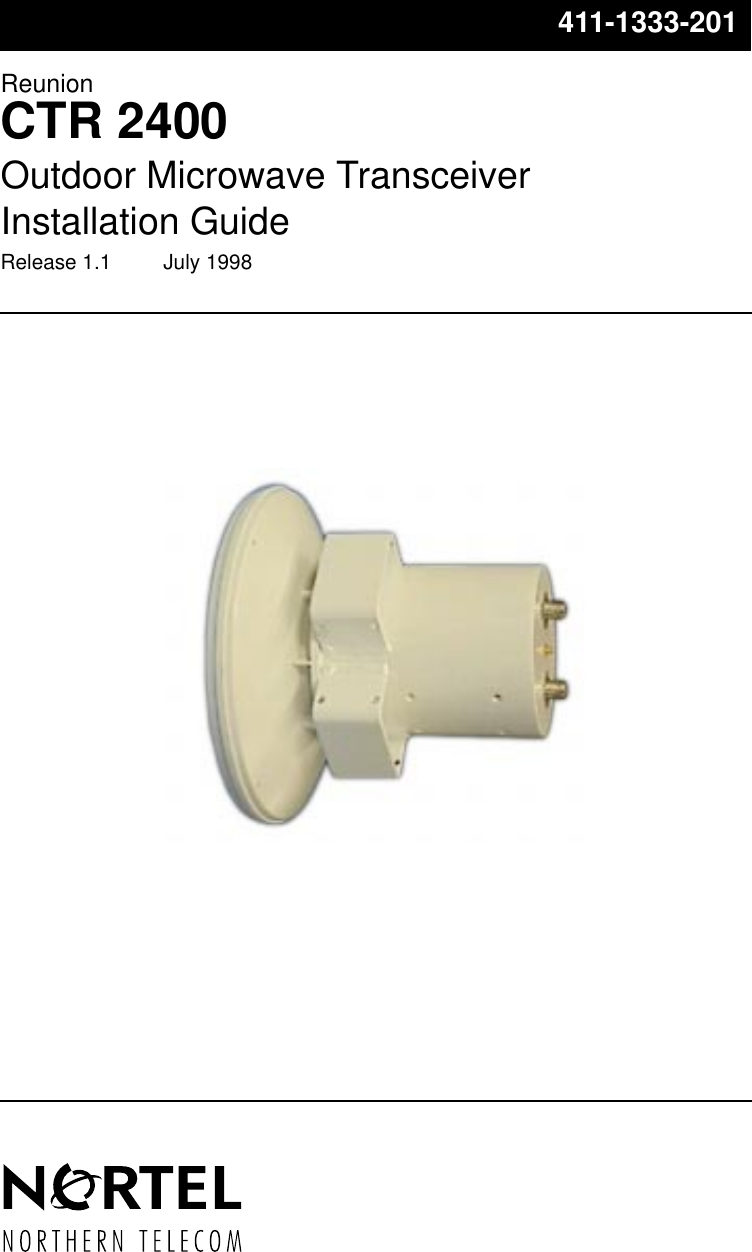
Nortel Networks BTRCTR2400-T 24GHz DEMS Transceiver User Manual

Nortel Networks Inc. 24GHz DEMS Transceiver

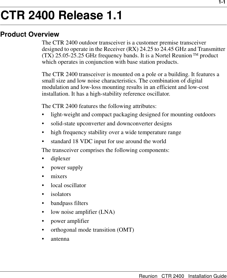
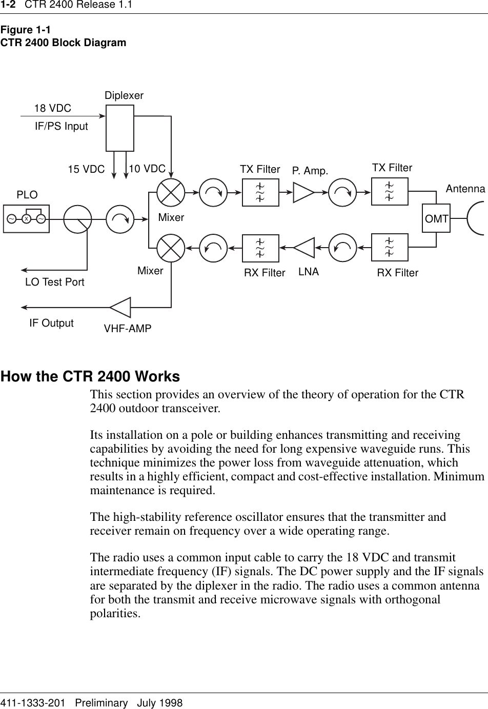
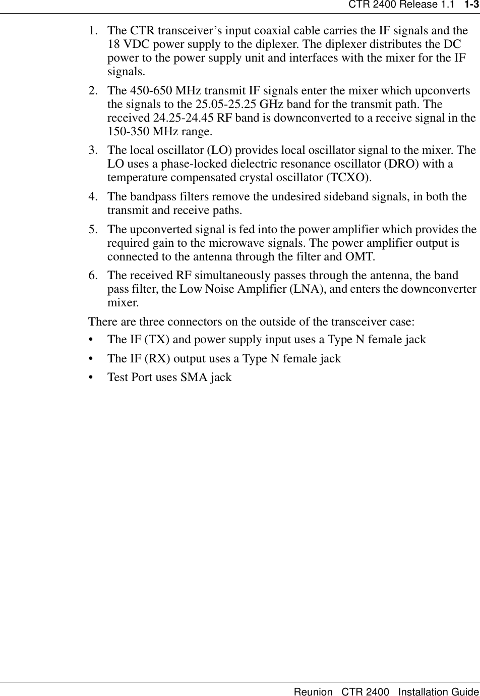
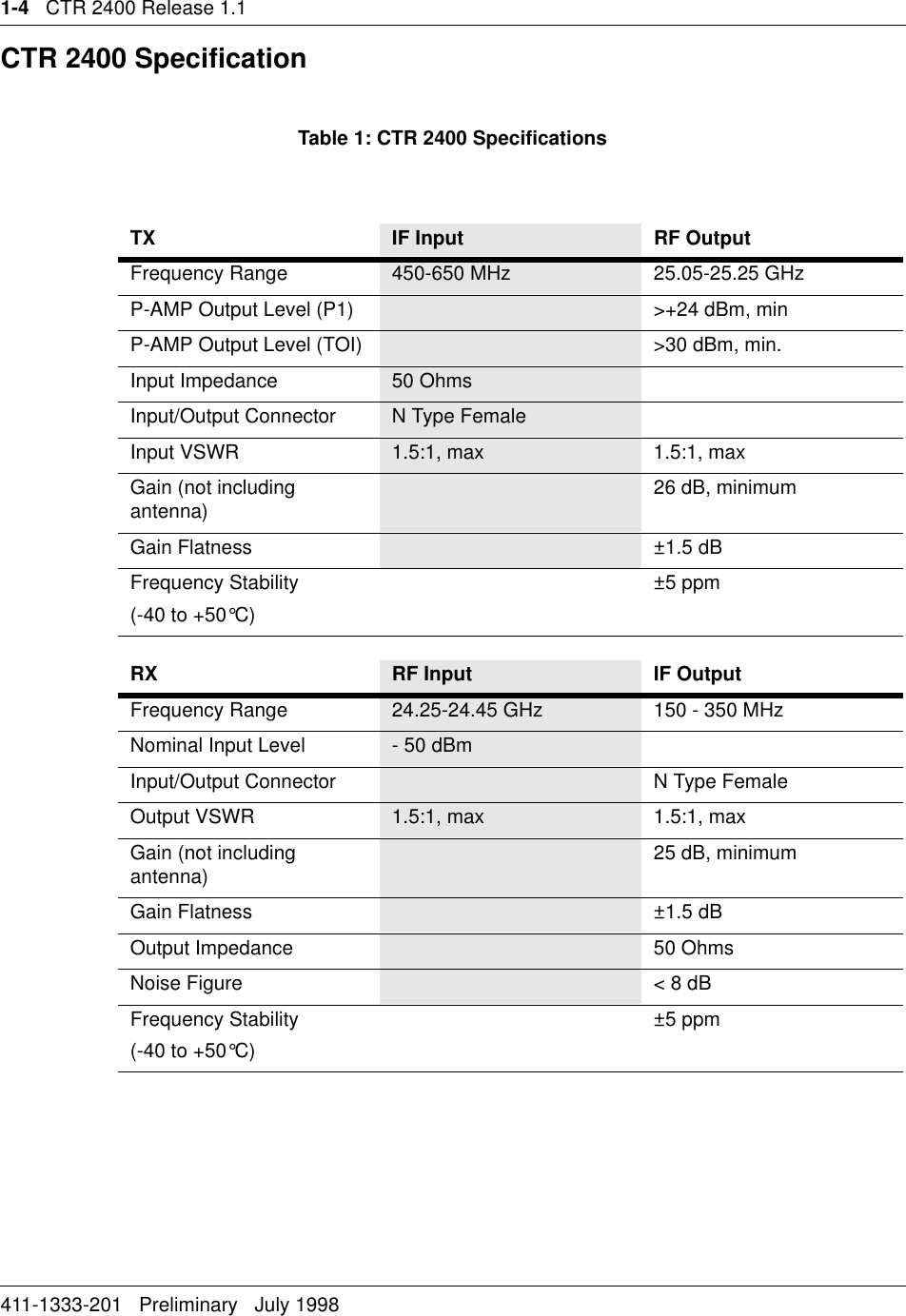
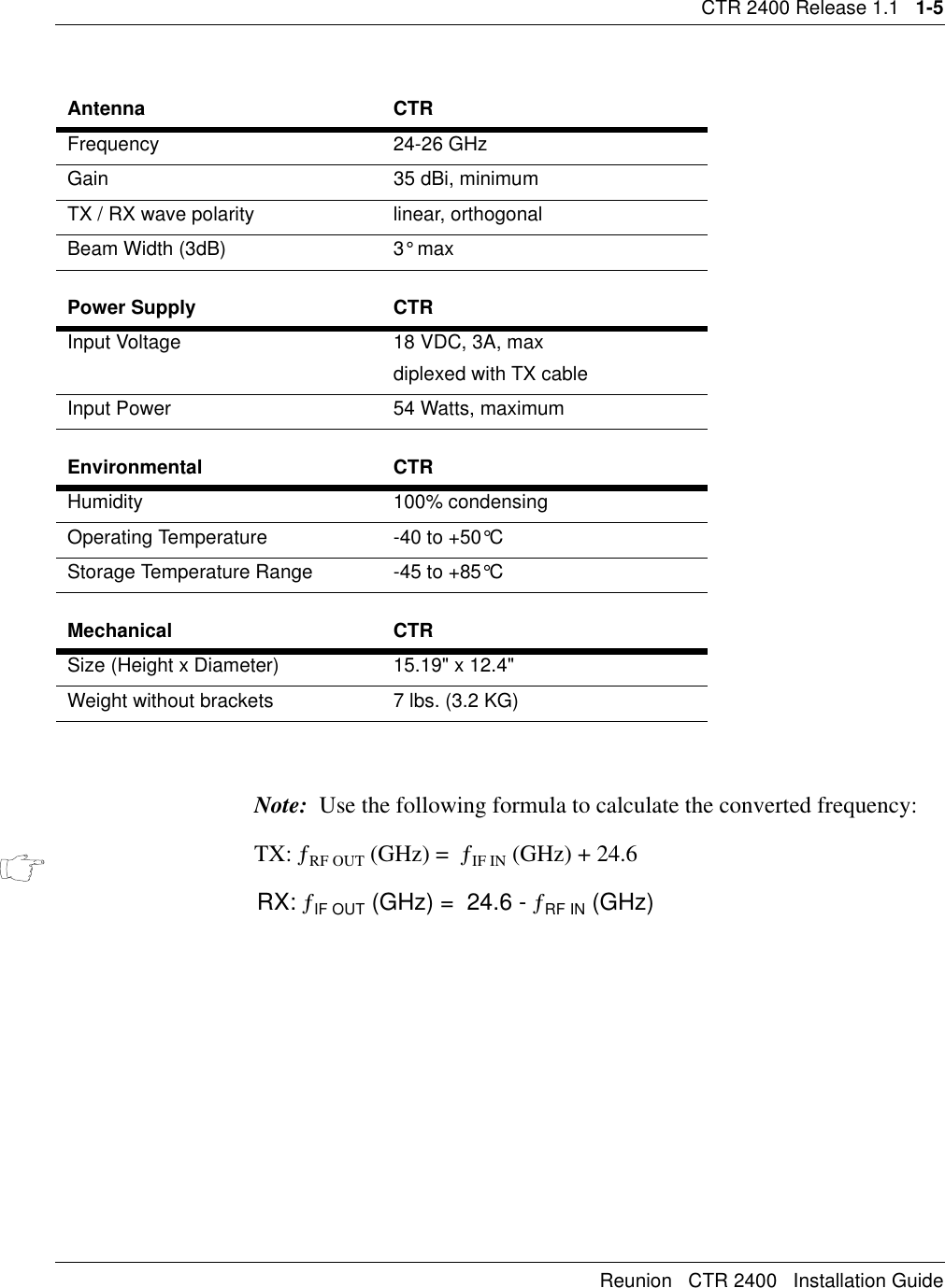
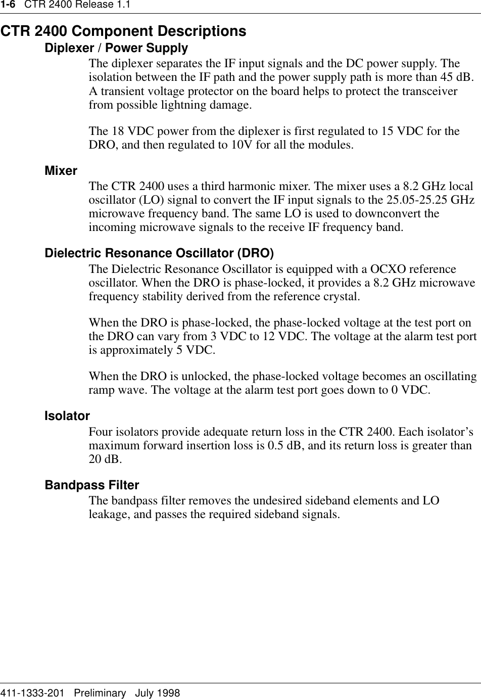
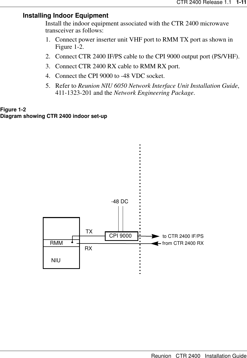
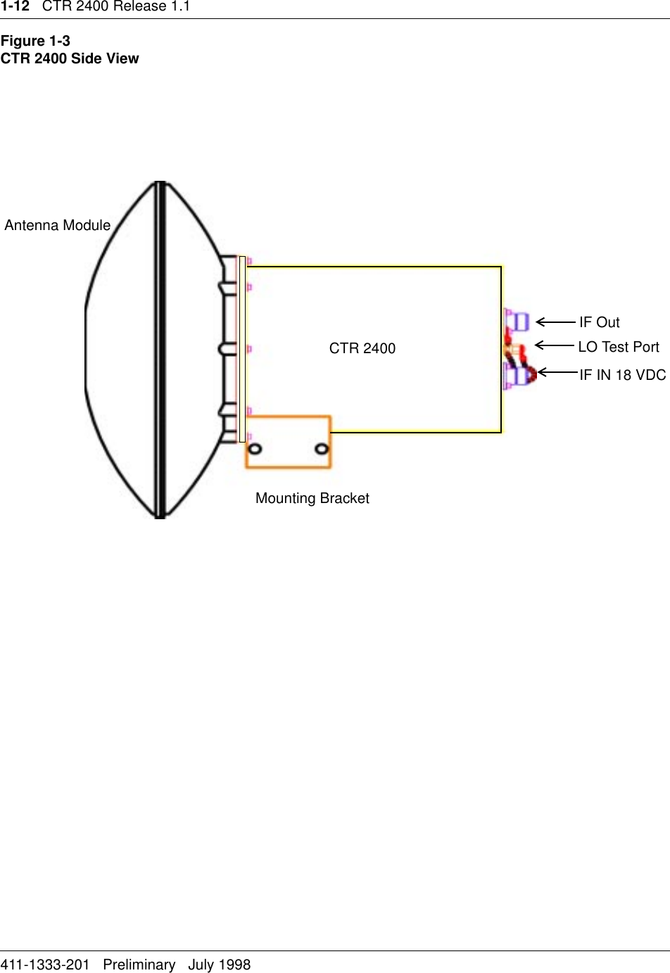
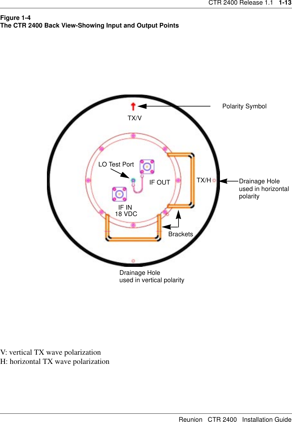
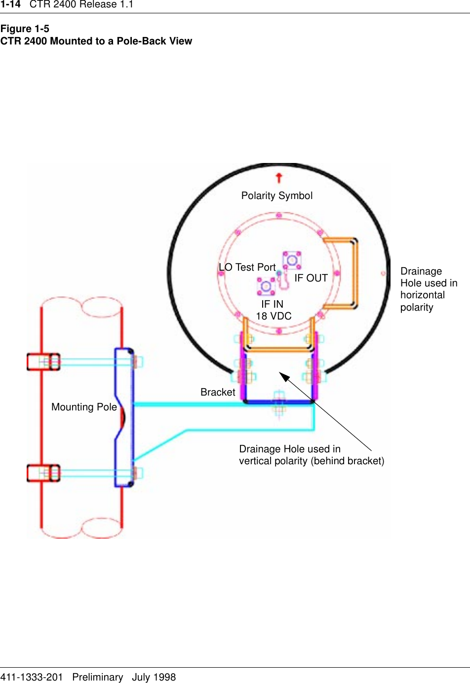
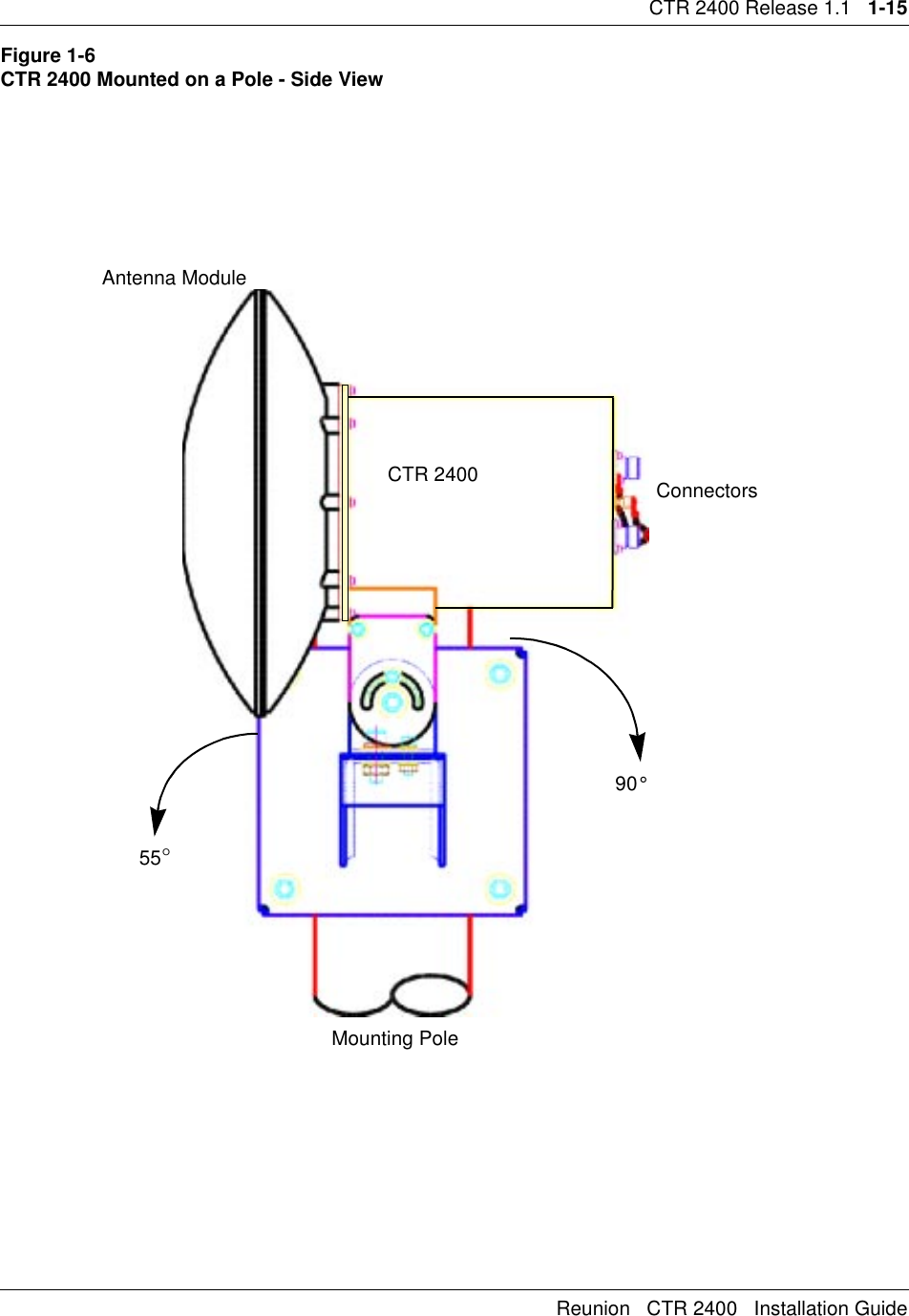
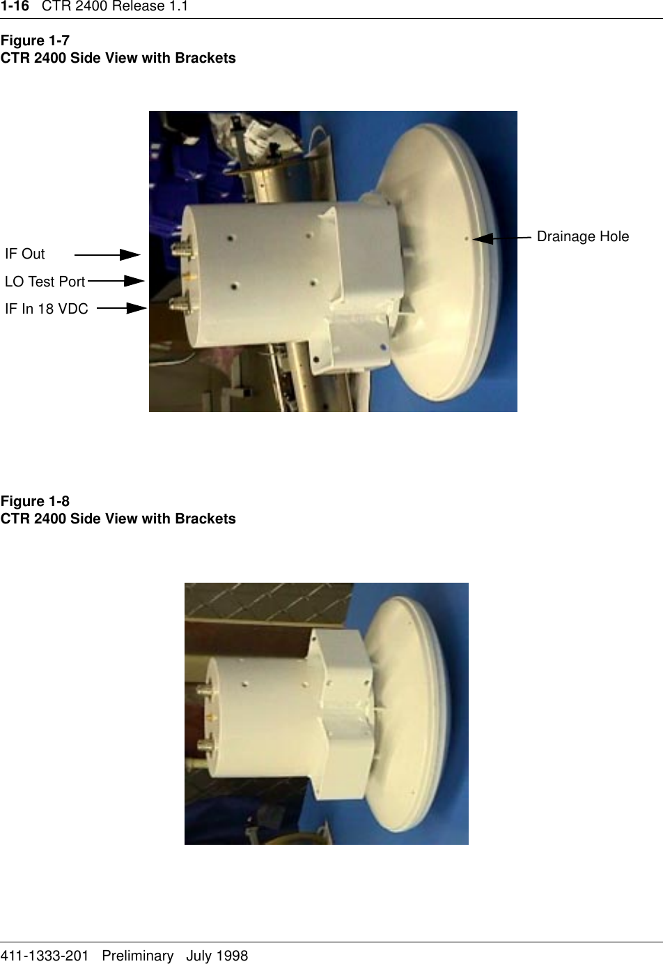
user manual for BTR2400 including block diagrams and operational description

ReunionCTR 2400Outdoor Microwave TransceiverInstallation GuideRelease 1.1         July 1998411-1333-201
ReunionCTR 2400Outdoor Microwave TransceiverInstallation GuideDocument number: 411-1333-201Product release:  Release 1.1Document version:   Preliminary Date:  July 1998Copyright Country of printing Confidentiality Legal statements Trademarks 1998 Northern TelecomNorthern Telecom Ltd., all rights reservedPrinted in CanadaNORTHERN TELECOM CONFIDENTIAL: The information contained in this document is the property of Northern Telecom.   Except as specifically authorized in writing by Northern Telecom, the holder of this document shall keep the information contained herein confidential and shall protect same in whole or in part from disclosure and dissemination to third parties and use same for evaluation, operation, and maintenance purposes only.Information is subject to change without notice.  REUNION TM is a trademark of Northern Telecom Ltd.
vReunion   CTR 2400   Installation  GuidePublication historyJuly 1998• Initial preliminary release of the document
vi   411-1333-201  Preliminary  July 1998
viiReunion   CTR 2400   Installation GuideAbout this guidePurposeThis guide provides the information required to install and operate the       CTR 2400 outdoor microwave transceiver.The CTR 2400 is one of the Radio Frequency (RF) products that constitute a Nortel Reunion TM product line. The associated products include the following types of cell site equipment: • broadband transmitters • broadband receivers• broadband repeaters• broadband transceiversAudienceThe audience for this document are those who install and operate the         CTR 2400. To take full advantage of this guide, you should have a basic understanding of microwave fundamentals and know how to use microwave test equipment.
viii   411-1333-201   Preliminary   July 1998OrganizationThis Guide is divided into seven sections:•Product Overview describes the CTR’s components and theory of operation.•Pre-Instalation describes the basics of handling the equipment upon arrival.•Reunion Safety Standards provide a quick review of general safety guidelines.•Installing the CTR 2400 explains how to physically install the transceiver.•CTR 2400 Maintenance describes basic maintenance procedures to ensure that the transceiver is operating correctly.•CTR 2400 Diagnostic Reference Chart provides a quick troubleshooting guide.•List of terms provides a quick reference to terms and acronyms found in the guide.Customer SupportIn addition, Nortel Broadband Wireless Access (BWA) provides 24-hour customer service and technical support to ensure your service operation is trouble-free. If you have questions or need technical support, contact Nortel Broadband Wireless Access at the following telephone numbers:• In the USA and Canada, call toll free 1 (800) 822-6355• Outside of North America, call (204) 631-2250• Fax (204) 631-2475Write Nortel at:• NortelBroadband Wireless Access37 Stevenson RoadWinnipeg, Manitoba R3H 0H9Canada
  ixReunion   CTR 2400   Installation GuideDocuments to fit Your NeedsThe CTR 2400 Installation Guide is designed to provide complete procedural and technical information needed to install, manage and operate this equipment.Nortel Broadband Wireless Access Customer Documentation and Training’s goal is to furnish concise, efficient and effective documentation that provides the customers and/or customer service personnel with the precise information required to operate and manage the specific Nortel Broadband Wireless Access equipment acquired. To help serve you better, please identify any information that you: • cannot find • had difficulty finding• think is important to include in the documentContact us at: • Customer Documentation and TrainingNortelBroadband Wireless Access37 Stevenson RoadWinnipeg, Manitoba R3H 0H9CanadaTel: (204) 631-2250; Fax: (204) 631-2475
x   411-1333-201   Preliminary   July 1998Documentation SuiteReunion Release 1.1 has a suite of eight documents:Reunion System Overview, 411-1343-010 Reunion System Administration Guide, 411-1343-011Reunion Network Node Equipment Installation Guide, 411-1313-200Reunion NIU 6050 Network Interface Unit Installation Guide, 411-1323-200Reunion BTR 2400 Outdoor Microwave Transceiver Installation Guide, 411-1333-200Reunion CTR 2400 Outdoor Microwave Transceiver Installation Guide, 411-1333-201Reunion Redundancy Switching Matrix Installation Guide, 411-1313-201Reunion DSS 1000 (Digital System Supervisor) User Guide, 411-1343-500
xiReunion   CTR 2400   Installation GuideContentsPublication history   vAbout this guide   viiPurpose   viiAudience   viiOrganization   viiiCustomer Support   viiiDocuments to fit Your Needs   ixDocumentation Suite   xContents   xiCTR 2400 Release 1.1  1-1Product Overview   1-1How the CTR 2400 Works   1-2CTR 2400 Specification   1-4CTR 2400 Component Descriptions   1-6Diplexer / Power Supply   1-6Mixer   1-6Dielectric Resonance Oscillator (DRO)   1-6Isolator   1-6Bandpass Filter   1-6Low Noise Amplifier   1-7Power Amplifier   1-7Orthogonal Mode Transition (OMT)   1-7Antenna   1-7Pre-Installation   1-8Prevention of Access   1-8Unpacking Shipment   1-8Reunion Safety Standards   1-9Safety Disclaimer   1-9General Safety   1-9Electrical Safety   1-9Installing the CTR 2400   1-10Installing the Tower Equipment   1-10Installing Indoor Equipment   1-11CTR 2400 Maintenance   1-17Mechanical Checks   1-17Grounding   1-17CTR 2400 Diagnostic Reference Chart   1-18
xii411-1333-201   Preliminary  July 1998List of terms  2-1
1-1Reunion   CTR 2400   Installation Guide1CTR 2400 Release 1.1Product OverviewThe CTR 2400 outdoor transceiver is a customer premise transceiver designed to operate in the Receiver (RX) 24.25 to 24.45 GHz and Transmitter (TX) 25.05-25.25 GHz frequency bands. It is a Nortel Reunion TM product which operates in conjunction with base station products. The CTR 2400 transceiver is mounted on a pole or a building. It features a small size and low noise characteristics. The combination of digital modulation and low-loss mounting results in an efficient and low-cost installation. It has a high-stability reference oscillator.The CTR 2400 features the following attributes:• light-weight and compact packaging designed for mounting outdoors • solid-state upconverter and downconverter designs• high frequency stability over a wide temperature range• standard 18 VDC input for use around the worldThe transceiver comprises the following components:• diplexer• power supply•mixers• local oscillator•isolators• bandpass filters• low noise amplifier (LNA)• power amplifier• orthogonal mode transition (OMT)• antenna
1-2   CTR 2400 Release 1.1411-1333-201   Preliminary   July 1998Figure 1-1 CTR 2400 Block DiagramHow the CTR 2400 WorksThis section provides an overview of the theory of operation for the CTR 2400 outdoor transceiver.Its installation on a pole or building enhances transmitting and receiving capabilities by avoiding the need for long expensive waveguide runs. This technique minimizes the power loss from waveguide attenuation, which results in a highly efficient, compact and cost-effective installation. Minimum maintenance is required.The high-stability reference oscillator ensures that the transmitter and receiver remain on frequency over a wide operating range. The radio uses a common input cable to carry the 18 VDC and transmit intermediate frequency (IF) signals. The DC power supply and the IF signals are separated by the diplexer in the radio. The radio uses a common antenna for both the transmit and receive microwave signals with orthogonal polarities.18 VDC Diplexer15 VDC 10 VDC TX Filter P. Amp. TX FilterAntennaOMTRX FilterLNARX FilterVHF-AMPIF OutputPLOMixerMixerLO Test PortIF/PS Input
CTR 2400 Release 1.1   1-3Reunion   CTR 2400   Installation Guide1. The CTR transceiver’s input coaxial cable carries the IF signals and the 18 VDC power supply to the diplexer. The diplexer distributes the DC power to the power supply unit and interfaces with the mixer for the IF signals.2. The 450-650 MHz transmit IF signals enter the mixer which upconverts the signals to the 25.05-25.25 GHz band for the transmit path. The received 24.25-24.45 RF band is downconverted to a receive signal in the 150-350 MHz range.3. The local oscillator (LO) provides local oscillator signal to the mixer. The LO uses a phase-locked dielectric resonance oscillator (DRO) with a temperature compensated crystal oscillator (TCXO).4. The bandpass filters remove the undesired sideband signals, in both the transmit and receive paths.5. The upconverted signal is fed into the power amplifier which provides the required gain to the microwave signals. The power amplifier output is connected to the antenna through the filter and OMT.6. The received RF simultaneously passes through the antenna, the band pass filter, the Low Noise Amplifier (LNA), and enters the downconverter mixer. There are three connectors on the outside of the transceiver case:• The IF (TX) and power supply input uses a Type N female jack                 • The IF (RX) output uses a Type N female jack • Test Port uses SMA jack
1-4   CTR 2400 Release 1.1411-1333-201   Preliminary   July 1998CTR 2400 SpecificationTable 1: CTR 2400 SpecificationsTX IF Input      RF OutputFrequency Range 450-650 MHz 25.05-25.25 GHzP-AMP Output Level (P1) >+24 dBm, minP-AMP Output Level (TOI) >30 dBm, min.Input Impedance 50 OhmsInput/Output Connector N Type FemaleInput VSWR 1.5:1, max 1.5:1, maxGain (not including antenna) 26 dB, minimumGain Flatness ±1.5 dBFrequency Stability (-40 to +50°C)±5 ppm RX RF Input      IF OutputFrequency Range 24.25-24.45 GHz  150 - 350 MHzNominal Input Level - 50 dBmInput/Output Connector   N Type FemaleOutput VSWR 1.5:1, max 1.5:1, maxGain (not including antenna) 25 dB, minimumGain Flatness ±1.5 dBOutput Impedance 50 OhmsNoise Figure < 8 dBFrequency Stability (-40 to +50°C) ±5 ppm
CTR 2400 Release 1.1   1-5Reunion   CTR 2400   Installation GuideNote:  Use the following formula to calculate the converted frequency:          TX: ƒRF OUT (GHz) =  ƒIF IN (GHz) + 24.6                               RX: ƒIF OUT (GHz) =  24.6 - ƒRF IN (GHz)                   Antenna CTRFrequency  24-26 GHzGain 35 dBi, minimumTX / RX wave polarity linear, orthogonalBeam Width (3dB) 3° maxPower Supply CTRInput Voltage 18 VDC, 3A, maxdiplexed with TX cableInput Power 54 Watts, maximumEnvironmental CTRHumidity 100% condensingOperating Temperature -40 to +50°CStorage Temperature Range -45 to +85°CMechanical CTRSize (Height x Diameter) 15.19" x 12.4" Weight without brackets 7 lbs. (3.2 KG)
1-6   CTR 2400 Release 1.1411-1333-201   Preliminary   July 1998CTR 2400 Component DescriptionsDiplexer / Power SupplyThe diplexer separates the IF input signals and the DC power supply. The isolation between the IF path and the power supply path is more than 45 dB. A transient voltage protector on the board helps to protect the transceiver from possible lightning damage.The 18 VDC power from the diplexer is first regulated to 15 VDC for the DRO, and then regulated to 10V for all the modules. Mixer The CTR 2400 uses a third harmonic mixer. The mixer uses a 8.2 GHz local oscillator (LO) signal to convert the IF input signals to the 25.05-25.25 GHz microwave frequency band. The same LO is used to downconvert the incoming microwave signals to the receive IF frequency band.Dielectric Resonance Oscillator (DRO)The Dielectric Resonance Oscillator is equipped with a OCXO reference oscillator. When the DRO is phase-locked, it provides a 8.2 GHz microwave frequency stability derived from the reference crystal.When the DRO is phase-locked, the phase-locked voltage at the test port on the DRO can vary from 3 VDC to 12 VDC. The voltage at the alarm test port is approximately 5 VDC.When the DRO is unlocked, the phase-locked voltage becomes an oscillating ramp wave. The voltage at the alarm test port goes down to 0 VDC.IsolatorFour isolators provide adequate return loss in the CTR 2400. Each isolator’s maximum forward insertion loss is 0.5 dB, and its return loss is greater than 20 dB.Bandpass FilterThe bandpass filter removes the undesired sideband elements and LO leakage, and passes the required sideband signals.
CTR 2400 Release 1.1   1-7Reunion   CTR 2400   Installation GuideLow Noise AmplifierThe low noise amplifier (LNA) provides gain in the receive path and amplifies the received microwave signals to the mixer. The gain and noise figure of the LNA are chosen to maximize the overall dynamic range and noise performance of the CTR 2400 receiver section.Power AmplifierThe power amplifier provides gain in the transmit path. It boosts the signals in the 25.05-25.25 GHz frequency range to the required level. The amplifier is a solid state amplifier that has high linearity within a high output power range.Orthogonal Mode Transition (OMT)The CTR 2400 uses the OMT to combine and separate the transmit and receive RF signals, allowing use of a common antenna for receiver and transmitter.AntennaThe CTR 2400 uses a reflector antenna to transmit and receive RF signals. The transmitting signal polarity is defined as the direction of CTR 2400 polarity. Note:  V= vertical TX wave polarization                 H= horizontal TX wave polarization
1-8   CTR 2400 Release 1.1411-1333-201   Preliminary   July 1998Pre-InstallationPrevention of AccessAllow only authorized personnel to access the equipment. Install the equipment in a restricted-access location or similar environment. Failure to prevent unauthorized user access invalidates the equipment warranty.Unpacking ShipmentUse the following steps to unpack and inspect the shipment of Nortel Broadband Wireless Access equipment:1. Copy adequate Inventory Forms2. Check each package against the order form and packing slip to ensure that all components are received3. Check each package for signs of damage4. Open the package and closely inspect all components for obvious signs of damage5. Know exactly where you are going to place the equipment, before removing them from the package 6. Carefully remove the equipment from the packaging7. Save packing material for future use8. Be aware of electrostatic discharge devices (ESD) requirements when handling BWA equipmentNote:  For more information, refer to the Electronic Industries Association (EIA) standard, Requirements for Handling Electrostatic-Discharge-Sensitive Devices (ESDS), EIA-625, as well as local and national standards.
CTR 2400 Release 1.1   1-9Reunion   CTR 2400   Installation GuideReunion Safety Standards Safety and safety considerations are important while using Nortel Broadband Wireless Access equipment. The following information is provided to assist you to establish appropriate safety practices.Safety DisclaimerThe safety standards discussed in this guide cannot address all safety issues associated with their use or all applicable regulatory requirements. You are responsible for establishing appropriate safety and health practices and to determine the applicability of regulatory limitations before their use.General SafetyEnsure that installation personnel are trained on CPR (Cardio Pulmonary Resuscitation), as well as on local, regional and national safety standards.When working on Nortel Broadband Wireless Access equipment, follow these guidelines:• Keep your work site clean and free of clutter.• Wear close fitting clothing.• Remove jewelry such as rings, bracelets, or watches.• Where it is possible to dislodge small pieces, wear eye protection.• Place equipment or cabinets on level surfaces.• Wear a safety belt when climbing a tower and installing equipment on a tower.• Work in pairs so that you have someone to help in case of an emergency.Electrical SafetyLocate the main power shut-off switch controlling the equipment you are working on. This is important in the event of an accident, so you can quickly cut the power.Disconnect all power when working on power supplies.In an emergency (electrocution):• shut the power off. • have someone call for emergency medical assistance•start CPRWarningDo not move in front of the antenna, nor look directly into the face of the antenna when the CTR 2400 is running.
1-10   CTR 2400 Release 1.1411-1333-201   Preliminary   July 1998Installing the CTR 2400Installation involves two separate operations:• installing the tower equipment• installing the indoor equipmentFor information about installing the antenna(s) and such aspects as line of sight, antenna mast spacing, coverage angle, etc., refer to the Network Engineering Package and the Design Document.Installing the Tower EquipmentInstall the CTR 2400 microwave transceiver as follows:1. Mount the CTR 2400 to a stable pole using the supplied mounting brackets. The mounting brackets accommodate poles with outside diameters from 2" to 4.5".  See Figures 1-5 and 1-6.      The CTR 2400 requires 18 VDC (3A) power supply unit. 2. Connect the IF/power supply input cable to the CTR’s N-type                   IF IN 18 VDC port. See Figures 1-3 and 1-4.3. Connect the RX cable from the CTR’s N-type IF OUT port to the RMM RX port. See Figures 1-3 and 1-4.4. Seal all connections using Coax-Seal® or equivalent, cold shrink or hot shrink tubing.5. Ground all RF cables at the recommended spacing intervals. (Refer to tower and cable manufacturers’ specifications).6. Ensure that all feed lines are securely attached to the support structure. Plan for drip (service) loops on all cables.WarningDo not turn on the power supply until the installation is complete.  After you install the equipment, check the cable connections.
CTR 2400 Release 1.1   1-11Reunion   CTR 2400   Installation GuideInstalling Indoor EquipmentInstall the indoor equipment associated with the CTR 2400 microwave transceiver as follows:1. Connect power inserter unit VHF port to RMM TX port as shown in Figure 1-2.2. Connect CTR 2400 IF/PS cable to the CPI 9000 output port (PS/VHF).3. Connect CTR 2400 RX cable to RMM RX port.4. Connect the CPI 9000 to -48 VDC socket. 5. Refer to Reunion NIU 6050 Network Interface Unit Installation Guide, 411-1323-201 and the Network Engineering Package.            Figure 1-2 Diagram showing CTR 2400 indoor set-upNIURMMTXRXto CTR 2400 IF/PSfrom CTR 2400 RXCPI 9000-48 DC
1-12   CTR 2400 Release 1.1411-1333-201   Preliminary   July 1998Figure 1-3CTR 2400 Side ViewCTR 2400Mounting BracketAntenna ModuleIF OutLO Test PortIF IN 18 VDC
CTR 2400 Release 1.1   1-13Reunion   CTR 2400   Installation GuideFigure 1-4The CTR 2400 Back View-Showing Input and Output Points V: vertical TX wave polarizationH: horizontal TX wave polarizationIF IN18 VDCIF OUTBracketsDrainage HoleLO Test PortTX/VTX/HPolarity SymbolDrainage Holeused in horizontalpolarityused in vertical polarity
1-14   CTR 2400 Release 1.1411-1333-201   Preliminary   July 1998Figure 1-5 CTR 2400 Mounted to a Pole-Back ViewBracketDrainage Hole used inPolarity SymbolMounting PoleIF IN18 VDCIF OUTLO Test Porthorizontalpolarity Drainage Hole used in vertical polarity (behind bracket)
CTR 2400 Release 1.1   1-15Reunion   CTR 2400   Installation GuideFigure 1-6 CTR 2400 Mounted on a Pole - Side ViewCTR 2400 ConnectorsAntenna ModuleMounting Pole90°55°
1-16   CTR 2400 Release 1.1411-1333-201   Preliminary   July 1998Figure 1-7 CTR 2400 Side View with Brackets Figure 1-8 CTR 2400 Side View with BracketsDrainage HoleIF OutLO Test PortIF In 18 VDC
CTR 2400 Release 1.1   1-17Reunion   CTR 2400   Installation GuideCTR 2400 MaintenanceEstablish a regular check procedure. This quickly identifies any problem which might develop. There are no repairable internal components in the CTR 2400. Therefore, the checks focus on the exterior features of the transceiver unit.Mechanical ChecksCheck the following mechanical areas to prevent problems.1. Check the bolts and fasteners which hold the transceiver, waveguides, and antenna. Vibrations due to wind can cause bolts and fasteners to loosen. Verify that equipment is secure and properly mounted. If the bolts or fasteners are loose, tighten them carefully. Use lock and spring washers.2. Check to ensure that all connections between the transceiver and antenna remain watertight. If water enters the waveguide or coaxial connections, it can cause attenuation of the microwave signals. If water is detected, call Nortel Broadband Wireless Access.3. Visually inspect all equipment for signs of external damage. If signs of damage are detected, call Nortel Broadband Wireless Access.Note:  If you detect an unsolvable problem during the electrical and mechanical inspections, contact Nortel Broadband Wireless Access so that action can be taken to rectify the problem.GroundingGrounding refers to a conducting body, for example the earth, used as a common return for an electronic circuit and as an arbitrary zero of potential.Grounding communication equipment limits voltage due to lightning, line surges or unintentional contact with higher voltage lines, by providing an alternative path. It minimizes damage to both the actual RF equipment and the indoor equipment to which it is connected.Grounding Reunion RF equipment is critical to ensure proper system operation, as well as protection of personnel and equipment.The CTR 2400 does not have a ‘ground point or stud.’ Its mounting to the pole serves as the ‘ground.’Also, the cables are ‘shielded’ or armored, and do not have a ground point/stud.
1-18   CTR 2400 Release 1.1411-1333-201   Preliminary   July 1998CTR 2400 Diagnostic Reference ChartNote:  Warranty void if seal is opened. This means do not attempt to remove cover.Symptom Possible Cause Check ProcedureOutput power low 1. VHF input signal level low. a. Check VHF signal level.b. Check coaxial cable.c. Check cable connectors. d. Check antenna for blockage (e.g. guano)No power a. check main fuse powerb. check cable connectionsIf you detect any problem during the electrical and mechanical checks, contact Nortel Broadband Wireless Access so that action can be taken to rectify the problem.
2-1Reunion   CTR 2400   Installation Guide2List of termsACAlternating CurrentAWGAmerican Wire GaugeDBMSDigital Broadband Microwave SystemDCDirect CurrentDRODielectric Resonance OscillatorEIAElectronic Industries AssociationESDElectrostatic DischargeFCCFederal Communications CommissionIC Industry CanadaIF Intermediate Frequency kHzkilohertz, one thousand hertz or cycles per second
2-2   List of terms411-1333-201 Preliminary July 1998LOLocal OscillatorLNALow Noise AmplifierLNBLow Noise Block DownconverterMHzMegaHertz, one million hertz or cycles per secondNIU Network Interface UnitOCXOOven-Controlled Crystal Oscillator OMTOrthogonal Mode TransitionPAPower AmplifierPI Power InserterPS Power SupplyQAMQuadrature Amplitude Modulation, which entails modulating frequencyRF Radio FrequencyRMMRadio Modem ModuleTCXOTemperature Compensated Crystal OscillatorVACVoltage Alternating Current
List of terms   2-3Reunion   CTR 2400   Installation GuideVDCVoltage Direct Current (Volts Direct Current)VHFVery High Frequency
2-4   List of terms411-1333-201 Preliminary July 1998
ReunionCTR 2400Installation GuideNortel Broadband Wireless Access37 Stevenson RoadWinnipeg, Manitoba R3H 0H9Phone:  1-800-822-6355 / Fax:  204-631-24751-800-4-NORTEL (1-800-466-7835)http://www.nortel.com 1998 Northern TelecomNorthern Telecom Ltd., all rights reservedNORTHERN TELECOM CONFIDENTIAL: The information contained in this document is the property of Northern Telecom. Except as specifically authorized in writing by Northern Telecom, the holder of this document shall keep the information contained herein confidential and shall protect same in whole or in part from disclosure and dissemination to third parties and use same for evaluation, operation, and maintenance purposes only.Information is subject to change without notice.  REUNION TM is a trademark of Northern Telecom Ltd.Publication number:  411-1333-201Product release : Release 1.1Document version:  PreliminaryDate:  July 1998Printed in Canada

Navigation menu