Nortel Networks BTRCTR2400-T 24GHz DEMS Transceiver User Manual
Nortel Networks Inc. 24GHz DEMS Transceiver
user manual for BTR2400 including block diagrams and operational description
Reunion
CTR 2400
Outdoor Microwave Transceiver
Installation Guide
Release 1.1 July 1998
411-1333-201

Reunion
CTR 2400
Outdoor Microwave Transceiver
Installation Guide
Document number: 411-1333-201
Product release: Release 1.1
Document version: Preliminary
Date: July 1998
Copyright Country of printing Confidentiality Legal statements Trademarks
1998 Northern Telecom
Northern Telecom Ltd., all rights reserved
Printed in Canada
NORTHERN TELECOM CONFIDENTIAL: The information contained in this document is the property of Northern
Telecom. Except as specifically authorized in writing by Northern Telecom, the holder of this document shall keep the information
contained herein confidential and shall protect same in whole or in part from disclosure and dissemination to third parties and use
same for evaluation, operation, and maintenance purposes only.
Information is subject to change without notice.
REUNION TM is a trademark of Northern Telecom Ltd.

v
Reunion CTR 2400 Installation Guide
Publication history
July 1998
• Initial preliminary release of the document

vi
411-1333-201 Preliminary July 1998

vii
Reunion CTR 2400 Installation Guide
About this guide
Purpose
This guide provides the information required to install and operate the
CTR 2400 outdoor microwave transceiver.
The CTR 2400 is one of the Radio Frequency (RF) products that constitute a
Nortel Reunion TM product line. The associated products include the following
types of cell site equipment:
• broadband transmitters
• broadband receivers
• broadband repeaters
• broadband transceivers
Audience
The audience for this document are those who install and operate the
CTR 2400. To take full advantage of this guide, you should have a basic
understanding of microwave fundamentals and know how to use microwave
test equipment.

viii
411-1333-201 Preliminary July 1998
Organization
This Guide is divided into seven sections:
•Product Overview describes the CTR’s components and theory of
operation.
•Pre-Instalation describes the basics of handling the equipment upon
arrival.
•Reunion Safety Standards provide a quick review of general safety
guidelines.
•Installing the CTR 2400 explains how to physically install the transceiver.
•CTR 2400 Maintenance describes basic maintenance procedures to ensure
that the transceiver is operating correctly.
•CTR 2400 Diagnostic Reference Chart provides a quick troubleshooting
guide.
•List of terms provides a quick reference to terms and acronyms found in
the guide.
Customer Support
In addition, Nortel Broadband Wireless Access (BWA) provides 24-hour
customer service and technical support to ensure your service operation is
trouble-free. If you have questions or need technical support, contact Nortel
Broadband Wireless Access at the following telephone numbers:
• In the USA and Canada, call toll free 1 (800) 822-6355
• Outside of North America, call (204) 631-2250
• Fax (204) 631-2475
Write Nortel at:
• Nortel
Broadband Wireless Access
37 Stevenson Road
Winnipeg, Manitoba R3H 0H9
Canada

ix
Reunion CTR 2400 Installation Guide
Documents to fit Your Needs
The CTR 2400 Installation Guide is designed to provide complete procedural
and technical information needed to install, manage and operate this
equipment.
Nortel Broadband Wireless Access Customer Documentation and Training’s
goal is to furnish concise, efficient and effective documentation that provides
the customers and/or customer service personnel with the precise information
required to operate and manage the specific Nortel Broadband Wireless
Access equipment acquired.
To help serve you better, please identify any information that you:
• cannot find
• had difficulty finding
• think is important to include in the document
Contact us at:
• Customer Documentation and Training
Nortel
Broadband Wireless Access
37 Stevenson Road
Winnipeg, Manitoba R3H 0H9
Canada
Tel: (204) 631-2250; Fax: (204) 631-2475

x
411-1333-201 Preliminary July 1998
Documentation Suite
Reunion Release 1.1 has a suite of eight documents:
Reunion System Overview, 411-1343-010
Reunion System Administration Guide, 411-1343-011
Reunion Network Node Equipment Installation Guide, 411-1313-200
Reunion NIU 6050 Network Interface Unit Installation Guide, 411-1323-200
Reunion BTR 2400 Outdoor Microwave Transceiver Installation Guide,
411-1333-200
Reunion CTR 2400 Outdoor Microwave Transceiver Installation Guide,
411-1333-201
Reunion Redundancy Switching Matrix Installation Guide, 411-1313-201
Reunion DSS 1000 (Digital System Supervisor) User Guide, 411-1343-500

xi
Reunion CTR 2400 Installation Guide
Contents
Publication history v
About this guide vii
Purpose vii
Audience vii
Organization viii
Customer Support viii
Documents to fit Your Needs ix
Documentation Suite x
Contents xi
CTR 2400 Release 1.1 1-1
Product Overview 1-1
How the CTR 2400 Works 1-2
CTR 2400 Specification 1-4
CTR 2400 Component Descriptions 1-6
Diplexer / Power Supply 1-6
Mixer 1-6
Dielectric Resonance Oscillator (DRO) 1-6
Isolator 1-6
Bandpass Filter 1-6
Low Noise Amplifier 1-7
Power Amplifier 1-7
Orthogonal Mode Transition (OMT) 1-7
Antenna 1-7
Pre-Installation 1-8
Prevention of Access 1-8
Unpacking Shipment 1-8
Reunion Safety Standards 1-9
Safety Disclaimer 1-9
General Safety 1-9
Electrical Safety 1-9
Installing the CTR 2400 1-10
Installing the Tower Equipment 1-10
Installing Indoor Equipment 1-11
CTR 2400 Maintenance 1-17
Mechanical Checks 1-17
Grounding 1-17
CTR 2400 Diagnostic Reference Chart 1-18


1-1
Reunion CTR 2400 Installation Guide
1CTR 2400 Release 1.1
Product Overview
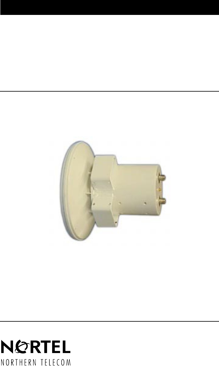
The CTR 2400 outdoor transceiver is a customer premise transceiver
designed to operate in the Receiver (RX) 24.25 to 24.45 GHz and Transmitter
(TX) 25.05-25.25 GHz frequency bands. It is a Nortel Reunion TM product
which operates in conjunction with base station products.
The CTR 2400 transceiver is mounted on a pole or a building. It features a
small size and low noise characteristics. The combination of digital
modulation and low-loss mounting results in an efficient and low-cost
installation. It has a high-stability reference oscillator.
The CTR 2400 features the following attributes:
• light-weight and compact packaging designed for mounting outdoors
• solid-state upconverter and downconverter designs
• high frequency stability over a wide temperature range
• standard 18 VDC input for use around the world
The transceiver comprises the following components:
• diplexer
• power supply
•mixers
• local oscillator
•isolators
• bandpass filters
• low noise amplifier (LNA)
• power amplifier
• orthogonal mode transition (OMT)
• antenna
1-2 CTR 2400 Release 1.1
411-1333-201 Preliminary July 1998
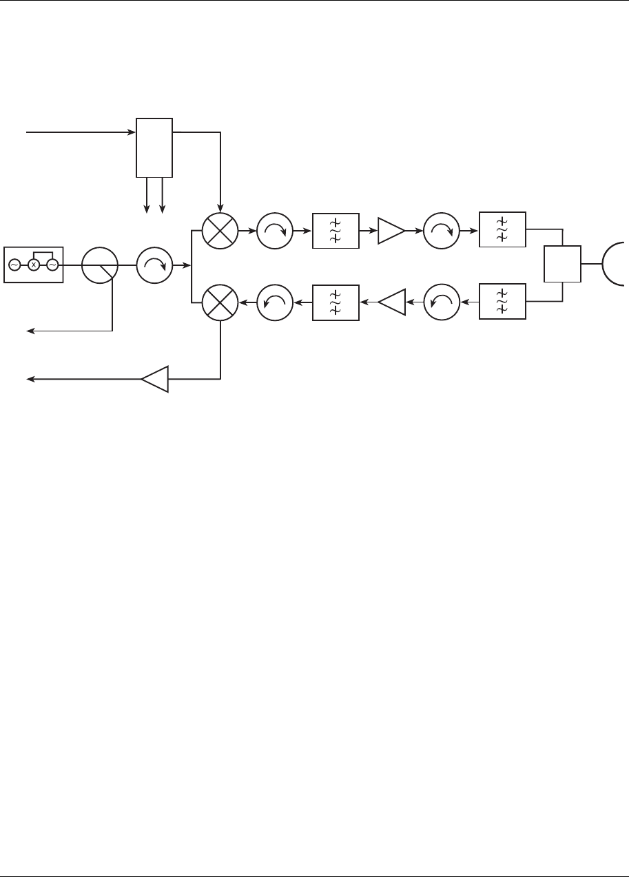
Figure 1-1
CTR 2400 Block Diagram
How the CTR 2400 Works
This section provides an overview of the theory of operation for the CTR
2400 outdoor transceiver.
Its installation on a pole or building enhances transmitting and receiving
capabilities by avoiding the need for long expensive waveguide runs. This
technique minimizes the power loss from waveguide attenuation, which
results in a highly efficient, compact and cost-effective installation. Minimum
maintenance is required.
The high-stability reference oscillator ensures that the transmitter and
receiver remain on frequency over a wide operating range.
The radio uses a common input cable to carry the 18 VDC and transmit
intermediate frequency (IF) signals. The DC power supply and the IF signals
are separated by the diplexer in the radio. The radio uses a common antenna
for both the transmit and receive microwave signals with orthogonal
polarities.
18 VDC Diplexer
15 VDC 10 VDC TX Filter P. Amp. TX Filter
Antenna
OMT
RX Filter
LNA
RX Filter
VHF-AMP
IF Output
PLO
Mixer
Mixer
LO Test Port
IF/PS Input

CTR 2400 Release 1.1 1-3
Reunion CTR 2400 Installation Guide
1. The CTR transceiver’s input coaxial cable carries the IF signals and the
18 VDC power supply to the diplexer. The diplexer distributes the DC
power to the power supply unit and interfaces with the mixer for the IF
signals.
2. The 450-650 MHz transmit IF signals enter the mixer which upconverts
the signals to the 25.05-25.25 GHz band for the transmit path. The
received 24.25-24.45 RF band is downconverted to a receive signal in the
150-350 MHz range.
3. The local oscillator (LO) provides local oscillator signal to the mixer. The
LO uses a phase-locked dielectric resonance oscillator (DRO) with a
temperature compensated crystal oscillator (TCXO).
4. The bandpass filters remove the undesired sideband signals, in both the
transmit and receive paths.
5. The upconverted signal is fed into the power amplifier which provides the
required gain to the microwave signals. The power amplifier output is
connected to the antenna through the filter and OMT.
6. The received RF simultaneously passes through the antenna, the band
pass filter, the Low Noise Amplifier (LNA), and enters the downconverter
mixer.
There are three connectors on the outside of the transceiver case:
• The IF (TX) and power supply input uses a Type N female jack
• The IF (RX) output uses a Type N female jack
• Test Port uses SMA jack

1-4 CTR 2400 Release 1.1
411-1333-201 Preliminary July 1998
CTR 2400 Specification
Table 1: CTR 2400 Specifications
TX IF Input RF Output
Frequency Range 450-650 MHz 25.05-25.25 GHz
P-AMP Output Level (P1) >+24 dBm, min
P-AMP Output Level (TOI) >30 dBm, min.
Input Impedance 50 Ohms
Input/Output Connector N Type Female
Input VSWR 1.5:1, max 1.5:1, max
Gain (not including
antenna) 26 dB, minimum
Gain Flatness ±1.5 dB
Frequency Stability
(-40 to +50°C)
±5 ppm
RX RF Input IF Output
Frequency Range 24.25-24.45 GHz 150 - 350 MHz
Nominal Input Level - 50 dBm
Input/Output Connector N Type Female
Output VSWR 1.5:1, max 1.5:1, max
Gain (not including
antenna) 25 dB, minimum
Gain Flatness ±1.5 dB
Output Impedance 50 Ohms
Noise Figure < 8 dB
Frequency Stability
(-40 to +50°C)
±5 ppm

CTR 2400 Release 1.1 1-5
Reunion CTR 2400 Installation Guide
Note: Use the following formula to calculate the converted frequency:
TX: ƒRF OUT (GHz) = ƒIF IN (GHz) + 24.6
RX: ƒIF OUT (GHz) = 24.6 - ƒRF IN (GHz)
Antenna CTR
Frequency 24-26 GHz
Gain 35 dBi, minimum
TX / RX wave polarity linear, orthogonal
Beam Width (3dB) 3° max
Power Supply CTR
Input Voltage 18 VDC, 3A, max
diplexed with TX cable
Input Power 54 Watts, maximum
Environmental CTR
Humidity 100% condensing
Operating Temperature -40 to +50°C
Storage Temperature Range -45 to +85°C
Mechanical CTR
Size (Height x Diameter) 15.19" x 12.4"
Weight without brackets 7 lbs. (3.2 KG)

1-6 CTR 2400 Release 1.1
411-1333-201 Preliminary July 1998
CTR 2400 Component Descriptions
Diplexer / Power Supply
The diplexer separates the IF input signals and the DC power supply. The
isolation between the IF path and the power supply path is more than 45 dB.
A transient voltage protector on the board helps to protect the transceiver
from possible lightning damage.
The 18 VDC power from the diplexer is first regulated to 15 VDC for the
DRO, and then regulated to 10V for all the modules.
Mixer The CTR 2400 uses a third harmonic mixer. The mixer uses a 8.2 GHz local
oscillator (LO) signal to convert the IF input signals to the 25.05-25.25 GHz
microwave frequency band. The same LO is used to downconvert the
incoming microwave signals to the receive IF frequency band.
Dielectric Resonance Oscillator (DRO)
The Dielectric Resonance Oscillator is equipped with a OCXO reference
oscillator. When the DRO is phase-locked, it provides a 8.2 GHz microwave
frequency stability derived from the reference crystal.
When the DRO is phase-locked, the phase-locked voltage at the test port on
the DRO can vary from 3 VDC to 12 VDC. The voltage at the alarm test port
is approximately 5 VDC.
When the DRO is unlocked, the phase-locked voltage becomes an oscillating
ramp wave. The voltage at the alarm test port goes down to 0 VDC.
IsolatorFour isolators provide adequate return loss in the CTR 2400. Each isolator’s
maximum forward insertion loss is 0.5 dB, and its return loss is greater than
20 dB.
Bandpass Filter
The bandpass filter removes the undesired sideband elements and LO
leakage, and passes the required sideband signals.

CTR 2400 Release 1.1 1-7
Reunion CTR 2400 Installation Guide
Low Noise Amplifier
The low noise amplifier (LNA) provides gain in the receive path and
amplifies the received microwave signals to the mixer. The gain and noise
figure of the LNA are chosen to maximize the overall dynamic range and
noise performance of the CTR 2400 receiver section.
Power Amplifier
The power amplifier provides gain in the transmit path. It boosts the signals in
the 25.05-25.25 GHz frequency range to the required level. The amplifier is a
solid state amplifier that has high linearity within a high output power range.
Orthogonal Mode Transition (OMT)
The CTR 2400 uses the OMT to combine and separate the transmit and
receive RF signals, allowing use of a common antenna for receiver and
transmitter.
Antenna
The CTR 2400 uses a reflector antenna to transmit and receive RF signals.
The transmitting signal polarity is defined as the direction of CTR 2400
polarity.
Note: V= vertical TX wave polarization
H= horizontal TX wave polarization

1-8 CTR 2400 Release 1.1
411-1333-201 Preliminary July 1998
Pre-Installation
Prevention of Access
Allow only authorized personnel to access the equipment. Install the
equipment in a restricted-access location or similar environment. Failure to
prevent unauthorized user access invalidates the equipment warranty.
Unpacking Shipment
Use the following steps to unpack and inspect the shipment of Nortel Broadband
Wireless Access equipment:
1. Copy adequate Inventory Forms
2. Check each package against the order form and packing slip to ensure that
all components are received
3. Check each package for signs of damage
4. Open the package and closely inspect all components for obvious signs of
damage
5. Know exactly where you are going to place the equipment, before
removing them from the package
6. Carefully remove the equipment from the packaging
7. Save packing material for future use
8. Be aware of electrostatic discharge devices (ESD) requirements when
handling BWA equipment
Note: For more information, refer to the Electronic Industries
Association (EIA) standard, Requirements for Handling Electrostatic-
Discharge-Sensitive Devices (ESDS), EIA-625, as well as local and
national standards.

CTR 2400 Release 1.1 1-9
Reunion CTR 2400 Installation Guide
Reunion Safety Standards
Safety and safety considerations are important while using Nortel Broadband
Wireless Access equipment. The following information is provided to assist
you to establish appropriate safety practices.
Safety Disclaimer
The safety standards discussed in this guide cannot address all safety issues
associated with their use or all applicable regulatory requirements. You are
responsible for establishing appropriate safety and health practices and to
determine the applicability of regulatory limitations before their use.
General Safety
Ensure that installation personnel are trained on CPR (Cardio Pulmonary
Resuscitation), as well as on local, regional and national safety standards.
When working on Nortel Broadband Wireless Access equipment, follow these
guidelines:
• Keep your work site clean and free of clutter.
• Wear close fitting clothing.
• Remove jewelry such as rings, bracelets, or watches.
• Where it is possible to dislodge small pieces, wear eye protection.
• Place equipment or cabinets on level surfaces.
• Wear a safety belt when climbing a tower and installing equipment on a
tower.
• Work in pairs so that you have someone to help in case of an emergency.
Electrical Safety
Locate the main power shut-off switch controlling the equipment you are
working on. This is important in the event of an accident, so you can quickly
cut the power.
Disconnect all power when working on power supplies.
In an emergency (electrocution):
• shut the power off.
• have someone call for emergency medical assistance
•start CPR
Warning
Do not move in front of the antenna, nor look
directly into the face of the antenna when the CTR
2400 is running.

1-10 CTR 2400 Release 1.1
411-1333-201 Preliminary July 1998
Installing the CTR 2400
Installation involves two separate operations:
• installing the tower equipment
• installing the indoor equipment
For information about installing the antenna(s) and such aspects as line of
sight, antenna mast spacing, coverage angle, etc., refer to the Network
Engineering Package and the Design Document.
Installing the Tower Equipment
Install the CTR 2400 microwave transceiver as follows:
1. Mount the CTR 2400 to a stable pole using the supplied mounting
brackets. The mounting brackets accommodate poles with outside
diameters from 2" to 4.5". See Figures 1-5 and 1-6.
The CTR 2400 requires 18 VDC (3A) power supply unit.
2. Connect the IF/power supply input cable to the CTR’s N-type
IF IN 18 VDC port. See Figures 1-3 and 1-4.
3. Connect the RX cable from the CTR’s N-type IF OUT port to the RMM
RX port. See Figures 1-3 and 1-4.
4. Seal all connections using Coax-Seal® or equivalent, cold shrink or hot
shrink tubing.
5. Ground all RF cables at the recommended spacing intervals. (Refer to
tower and cable manufacturers’ specifications).
6. Ensure that all feed lines are securely attached to the support structure.
Plan for drip (service) loops on all cables.
Warning
Do not turn on the power supply until the
installation is complete. After you install the
equipment, check the cable connections.
CTR 2400 Release 1.1 1-11
Reunion CTR 2400 Installation Guide
Installing Indoor Equipment
Install the indoor equipment associated with the CTR 2400 microwave
transceiver as follows:
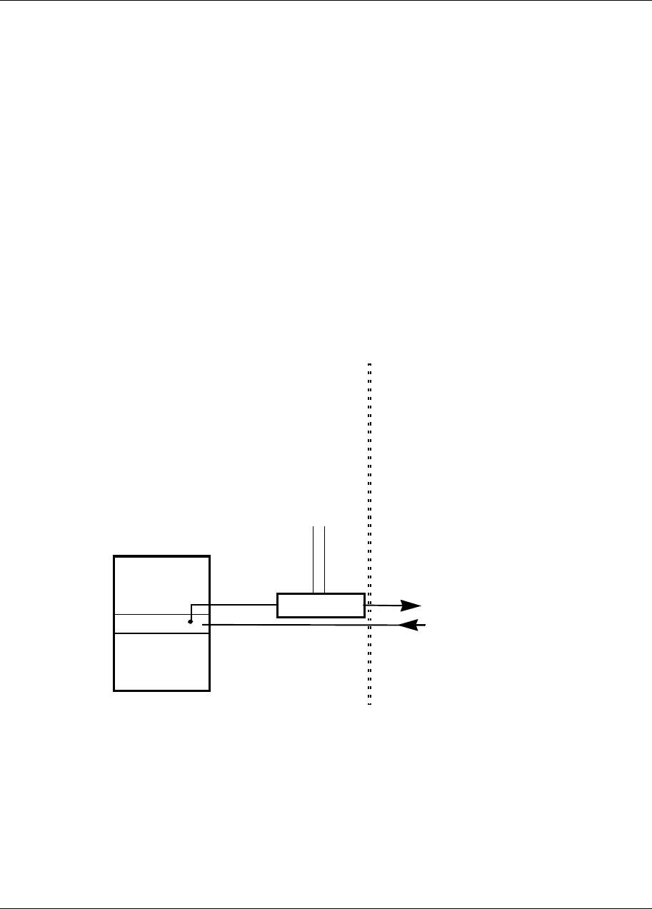
1. Connect power inserter unit VHF port to RMM TX port as shown in
Figure 1-2.
2. Connect CTR 2400 IF/PS cable to the CPI 9000 output port (PS/VHF).
3. Connect CTR 2400 RX cable to RMM RX port.
4. Connect the CPI 9000 to -48 VDC socket.
5. Refer to Reunion NIU 6050 Network Interface Unit Installation Guide,
411-1323-201 and the Network Engineering Package.
Figure 1-2
Diagram showing CTR 2400 indoor set-up
NIU
RMM
TX
RX
to CTR 2400 IF/PS
from CTR 2400 RX
CPI 9000
-48 DC
1-12 CTR 2400 Release 1.1
411-1333-201 Preliminary July 1998
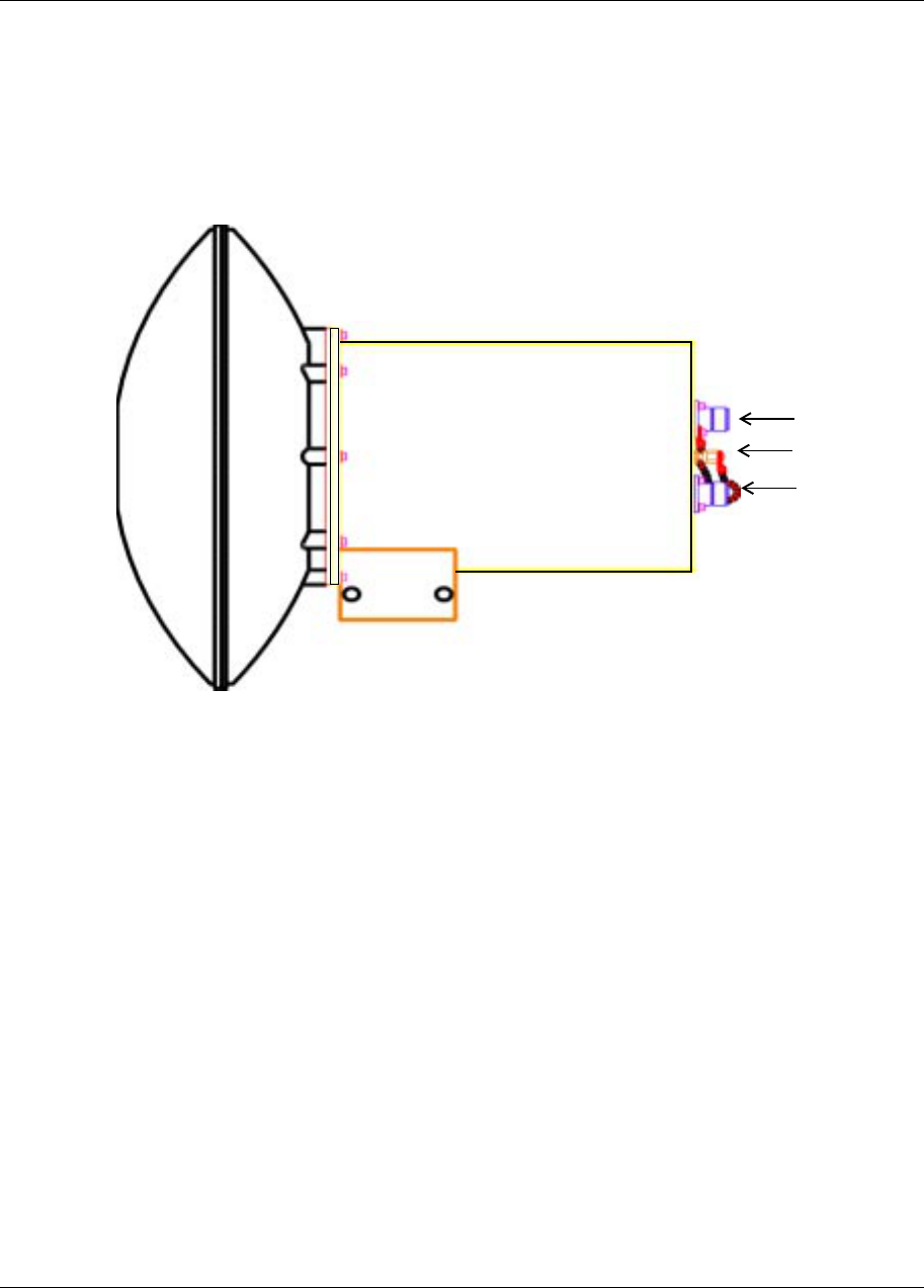
Figure 1-3
CTR 2400 Side View
CTR 2400
Mounting Bracket
Antenna Module
IF Out
LO Test Port
IF IN 18 VDC
CTR 2400 Release 1.1 1-13
Reunion CTR 2400 Installation Guide
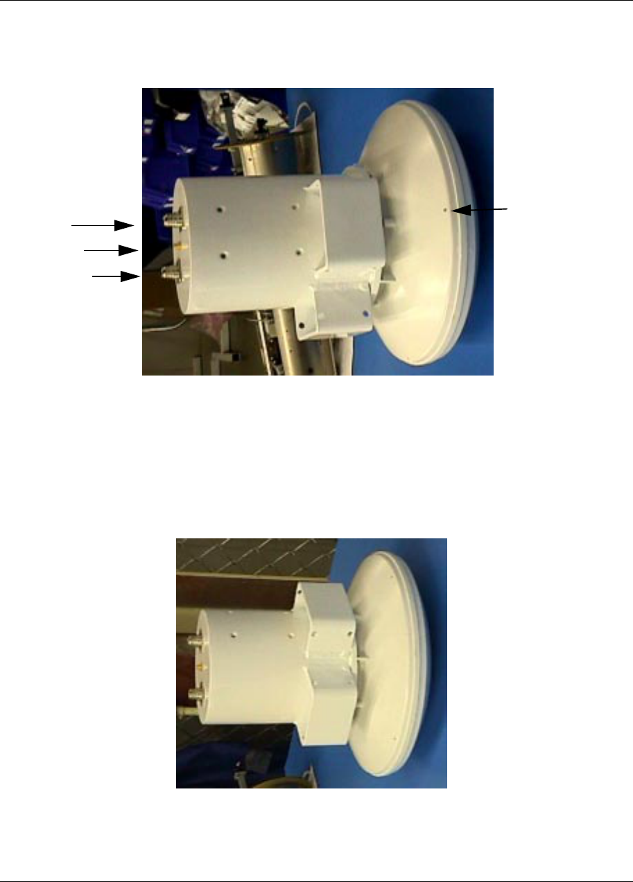
Figure 1-4
The CTR 2400 Back View-Showing Input and Output Points
V: vertical TX wave polarization
H: horizontal TX wave polarization
IF IN
18 VDC
IF OUT
Brackets
Drainage Hole
LO Test Port
TX/V
TX/H
Polarity Symbol
Drainage Hole
used in horizontal
polarity
used in vertical polarity
1-14 CTR 2400 Release 1.1
411-1333-201 Preliminary July 1998
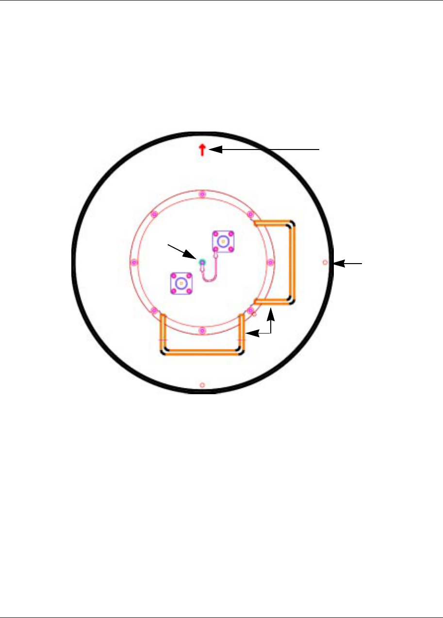
Figure 1-5
CTR 2400 Mounted to a Pole-Back View
Bracket
Drainage
Hole used in
Polarity Symbol
Mounting Pole
IF IN
18 VDC
IF OUT
LO Test Port
horizontal
polarity
Drainage Hole used in
vertical polarity (behind bracket)
CTR 2400 Release 1.1 1-15
Reunion CTR 2400 Installation Guide
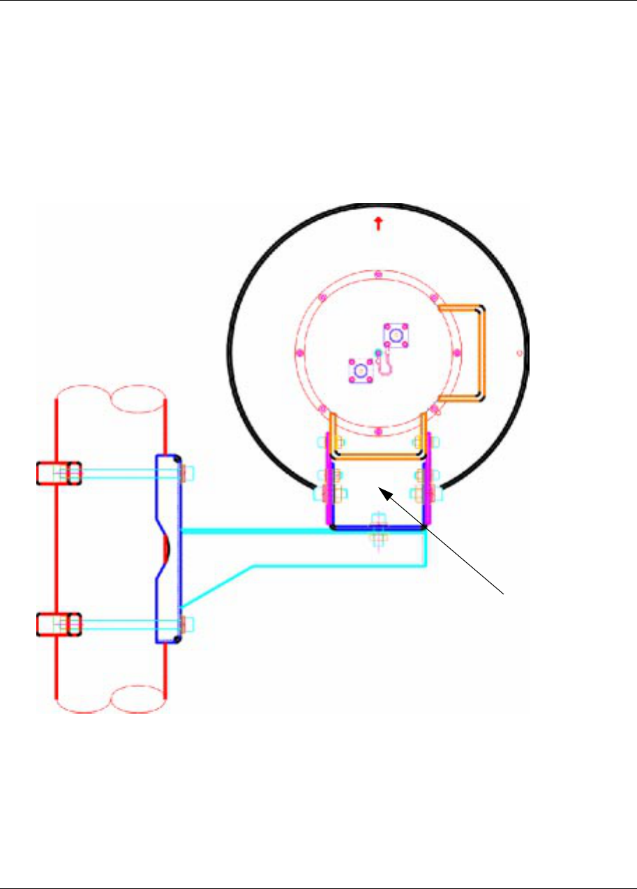
Figure 1-6
CTR 2400 Mounted on a Pole - Side View
CTR 2400 Connectors
Antenna Module
Mounting Pole
90°
55°
1-16 CTR 2400 Release 1.1
411-1333-201 Preliminary July 1998
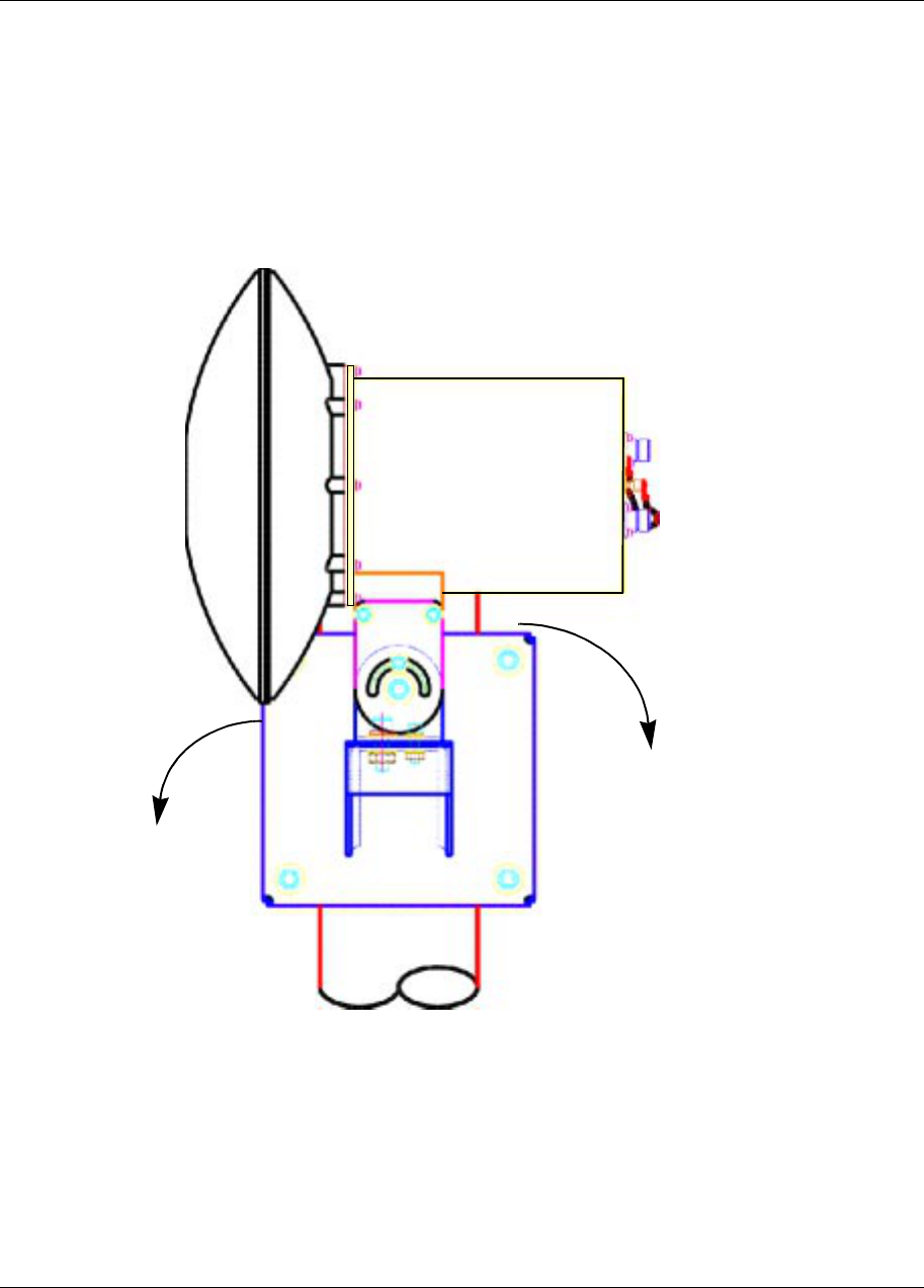
Figure 1-7
CTR 2400 Side View with Brackets
Figure 1-8
CTR 2400 Side View with Brackets
Drainage Hole
IF Out
LO Test Port
IF In 18 VDC

CTR 2400 Release 1.1 1-17
Reunion CTR 2400 Installation Guide
CTR 2400 Maintenance
Establish a regular check procedure. This quickly identifies any problem
which might develop. There are no repairable internal components in the
CTR 2400. Therefore, the checks focus on the exterior features of the
transceiver unit.
Mechanical Checks
Check the following mechanical areas to prevent problems.
1. Check the bolts and fasteners which hold the transceiver, waveguides, and
antenna. Vibrations due to wind can cause bolts and fasteners to loosen.
Verify that equipment is secure and properly mounted. If the bolts or
fasteners are loose, tighten them carefully. Use lock and spring washers.
2. Check to ensure that all connections between the transceiver and antenna
remain watertight. If water enters the waveguide or coaxial connections, it
can cause attenuation of the microwave signals. If water is detected, call
Nortel Broadband Wireless Access.
3. Visually inspect all equipment for signs of external damage. If signs of
damage are detected, call Nortel Broadband Wireless Access.
Note: If you detect an unsolvable problem during the electrical and
mechanical inspections, contact Nortel Broadband Wireless Access so
that action can be taken to rectify the problem.
Grounding
Grounding refers to a conducting body, for example the earth, used as a
common return for an electronic circuit and as an arbitrary zero of potential.
Grounding communication equipment limits voltage due to lightning, line
surges or unintentional contact with higher voltage lines, by providing an
alternative path. It minimizes damage to both the actual RF equipment and
the indoor equipment to which it is connected.
Grounding Reunion RF equipment is critical to ensure proper system
operation, as well as protection of personnel and equipment.
The CTR 2400 does not have a ‘ground point or stud.’ Its mounting to the
pole serves as the ‘ground.’
Also, the cables are ‘shielded’ or armored, and do not have a ground point/
stud.

1-18 CTR 2400 Release 1.1
411-1333-201 Preliminary July 1998
CTR 2400 Diagnostic Reference Chart
Note: Warranty void if seal is opened. This means do not attempt to
remove cover.
Symptom Possible Cause Check Procedure
Output power low 1. VHF input signal level low. a. Check VHF signal level.
b. Check coaxial cable.
c. Check cable connectors.
d. Check antenna for blockage (e.g. guano)
No power a. check main fuse power
b. check cable connections
If you detect any problem during the electrical and mechanical checks, contact Nortel
Broadband Wireless Access so that action can be taken to rectify the problem.

2-1
Reunion CTR 2400 Installation Guide
2List of terms
ACAlternating Current
AWG
American Wire Gauge
DBMS
Digital Broadband Microwave System
DCDirect Current
DRO
Dielectric Resonance Oscillator
EIAElectronic Industries Association
ESD
Electrostatic Discharge
FCC
Federal Communications Commission
IC Industry Canada
IF Intermediate Frequency
kHz
kilohertz, one thousand hertz or cycles per second

2-2 List of terms
411-1333-201 Preliminary July 1998
LOLocal Oscillator
LNA
Low Noise Amplifier
LNB
Low Noise Block Downconverter
MHz
MegaHertz, one million hertz or cycles per second
NIU
Network Interface Unit
OCXO
Oven-Controlled Crystal Oscillator
OMT
Orthogonal Mode Transition
PAPower Amplifier
PI Power Inserter
PS Power Supply
QAM
Quadrature Amplitude Modulation, which entails modulating frequency
RF Radio Frequency
RMM
Radio Modem Module
TCXO
Temperature Compensated Crystal Oscillator
VAC
Voltage Alternating Current

List of terms 2-3
Reunion CTR 2400 Installation Guide
VDC
Voltage Direct Current (Volts Direct Current)
VHF
Very High Frequency

2-4 List of terms
411-1333-201 Preliminary July 1998
Family Product Manual Contacts Copyright Confidentiality Legal statements DocInfo

Reunion
CTR 2400
Installation Guide
Nortel Broadband Wireless Access
37 Stevenson Road
Winnipeg, Manitoba R3H 0H9
Phone: 1-800-822-6355 / Fax: 204-631-2475
1-800-4-NORTEL (1-800-466-7835)
http://www.nortel.com
1998 Northern Telecom
Northern Telecom Ltd., all rights reserved
NORTHERN TELECOM CONFIDENTIAL:
The information contained in this document is the property of
Northern Telecom. Except as specifically authorized in writing by
Northern Telecom, the holder of this document shall keep the
information contained herein confidential and shall protect same
in whole or in part from disclosure and dissemination to third
parties and use same for evaluation, operation, and
maintenance purposes only.
Information is subject to change without notice.
REUNION TM is a trademark of Northern Telecom Ltd.
Publication number: 411-1333-201
Product release : Release 1.1
Document version: Preliminary
Date: July 1998
Printed in Canada