Nortel Networks BTRCTR380002-N 38GHz Microwave Transceiver (variant 2) User Manual
Nortel Networks Inc. 38GHz Microwave Transceiver (variant 2)
UserManual.wiki
>
Nortel Networks
>
BTRCTR380002-N User Manual
>
BTR User Manual
Contents
1.
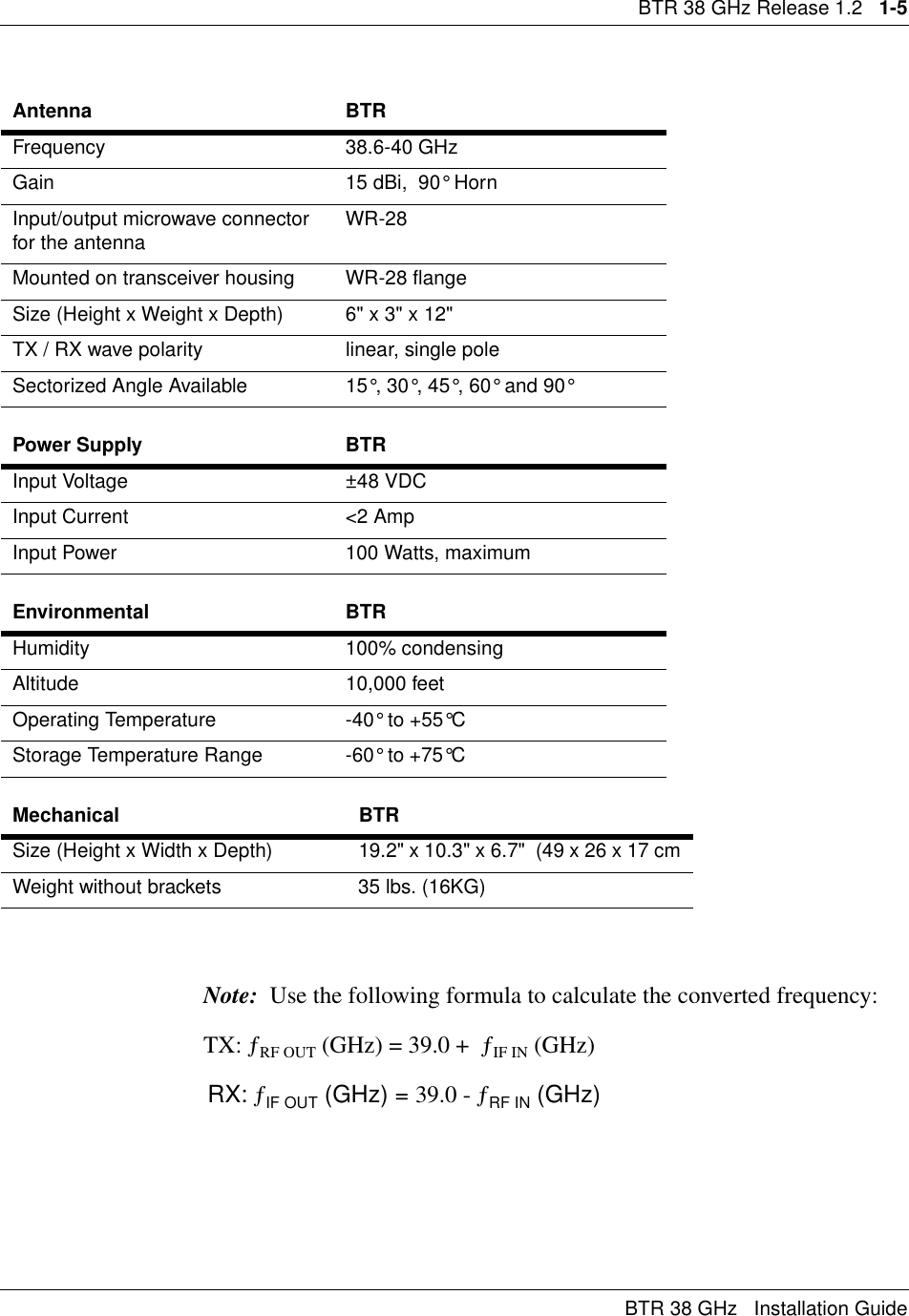
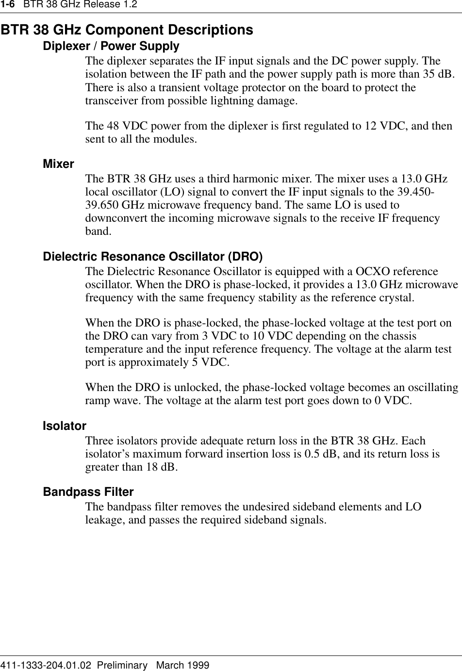
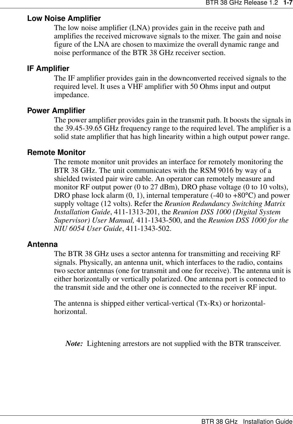
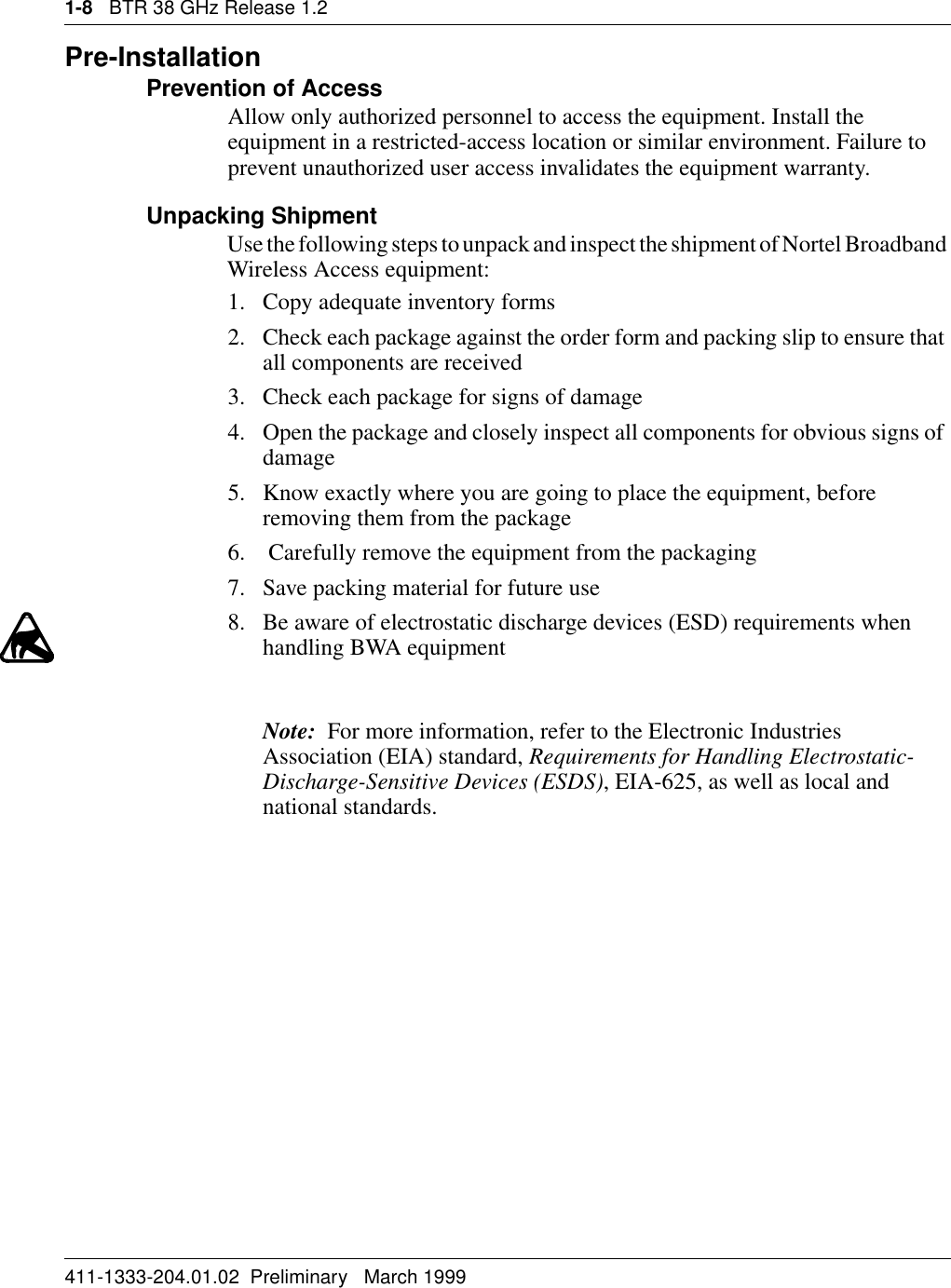
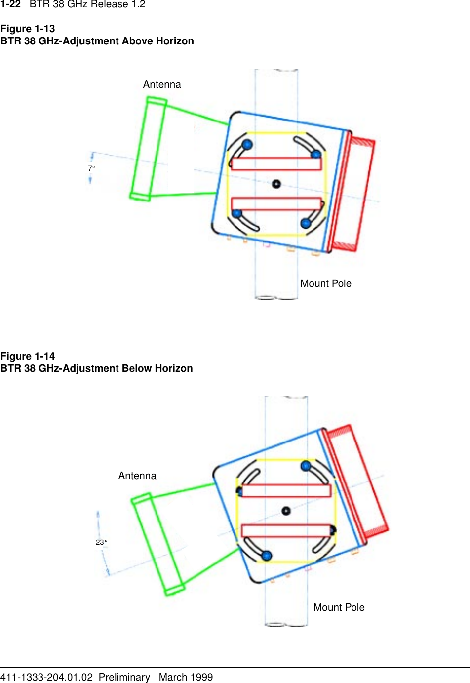
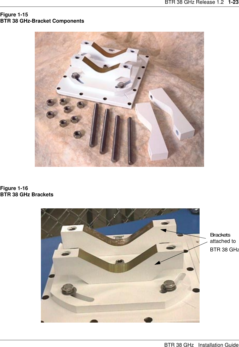
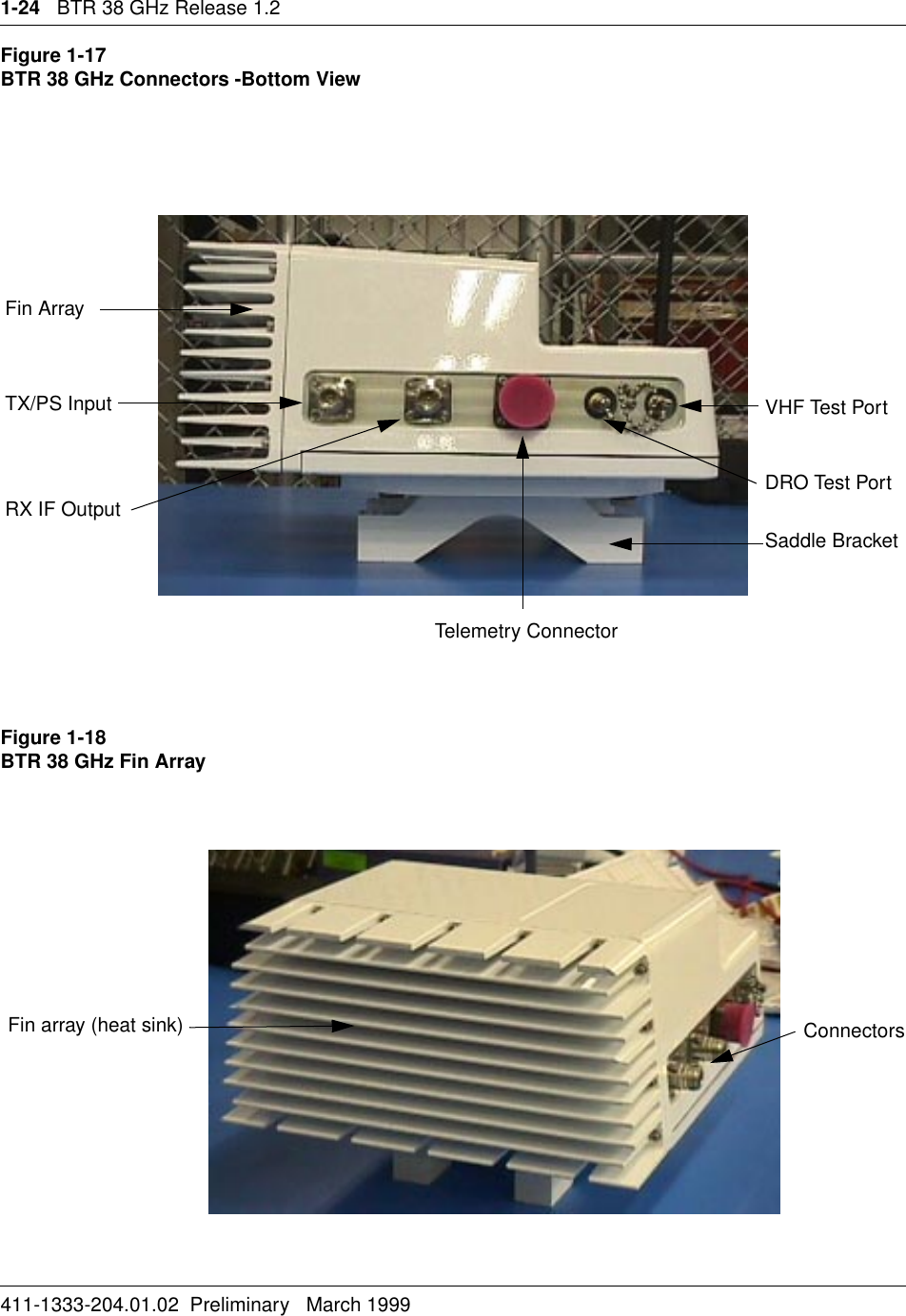
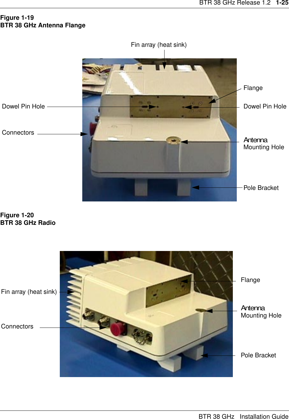
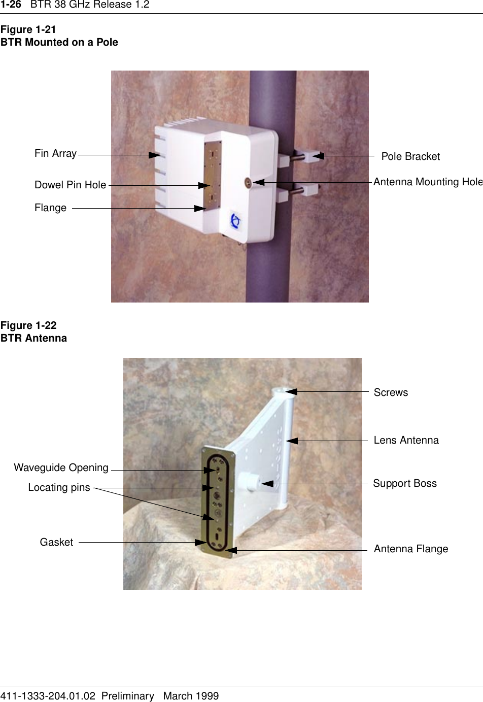
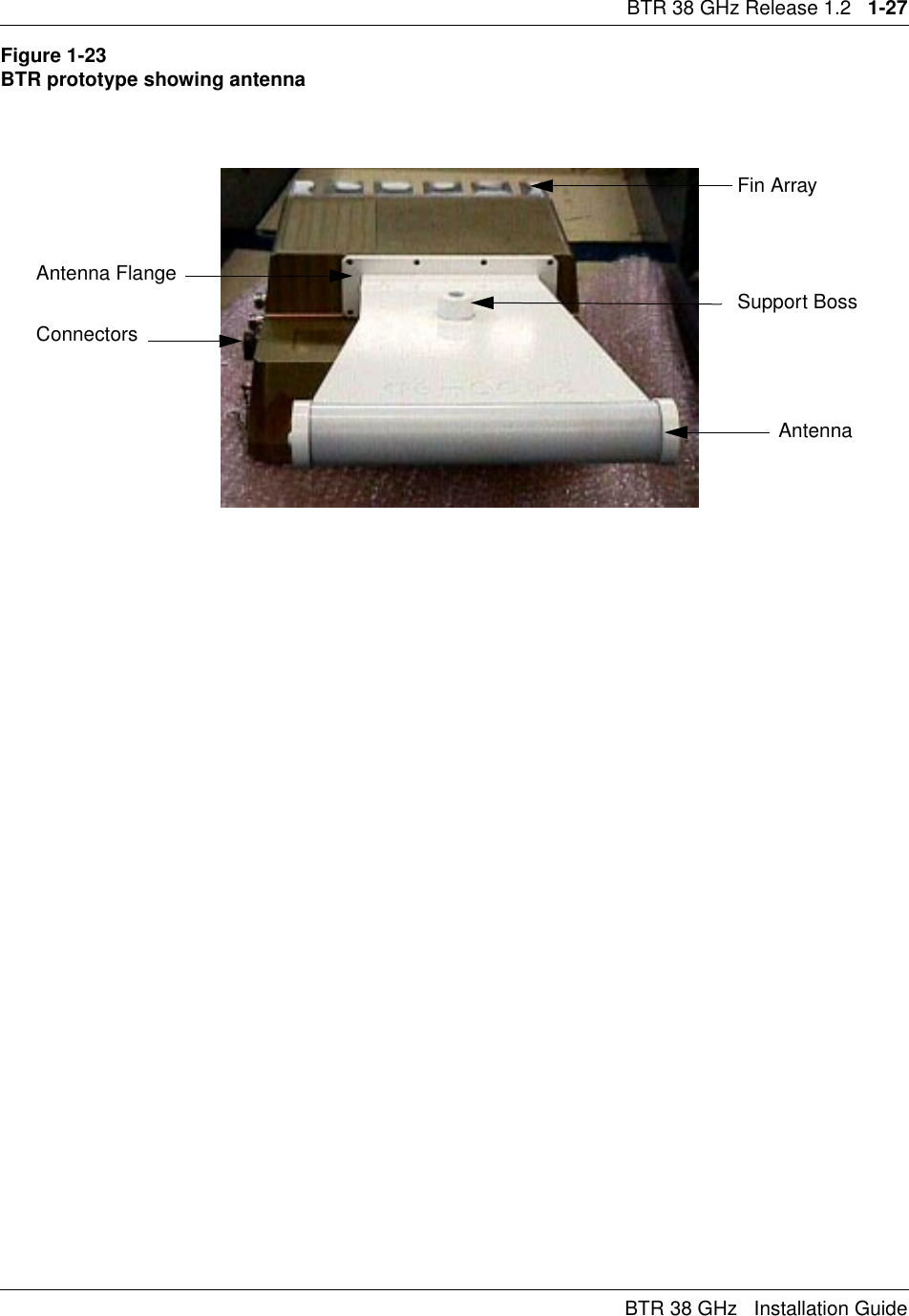
BTR User Manual
2.
CTR User Manual
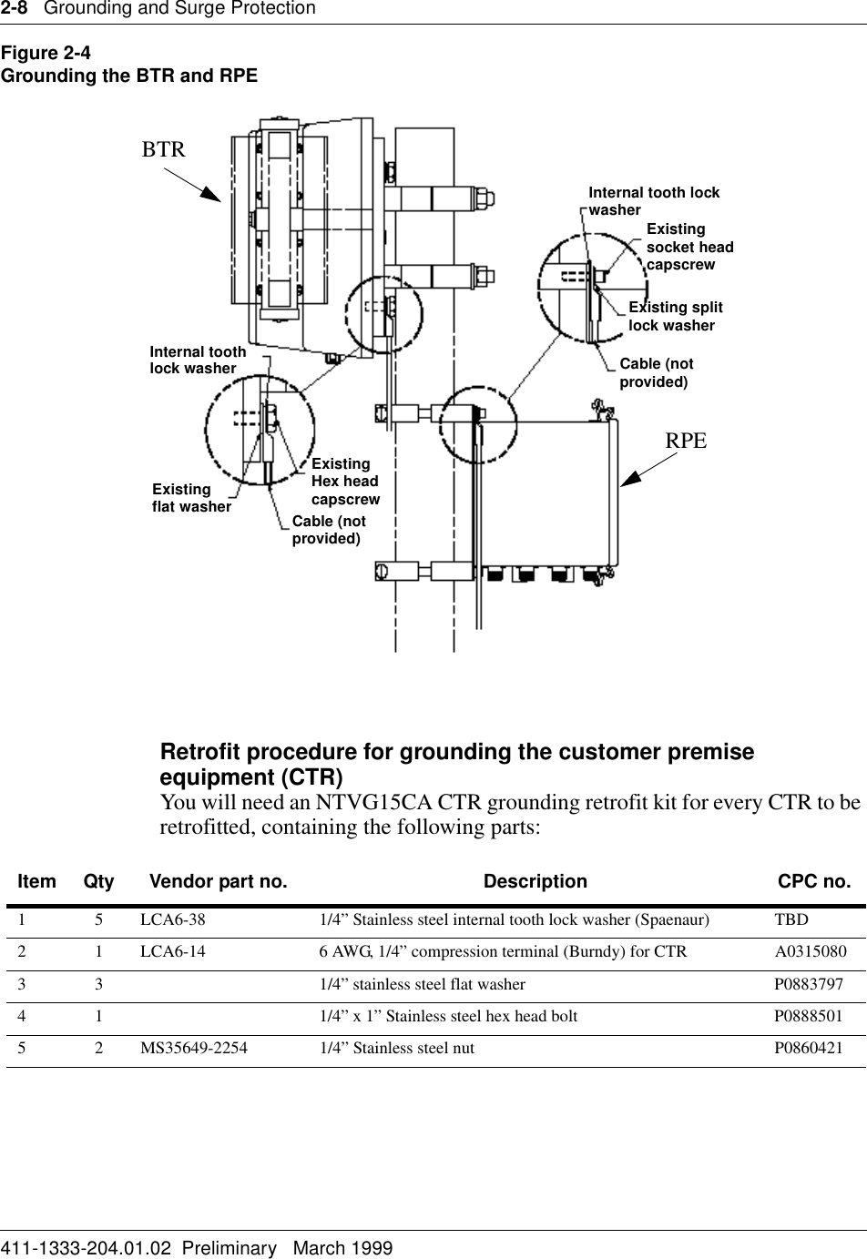
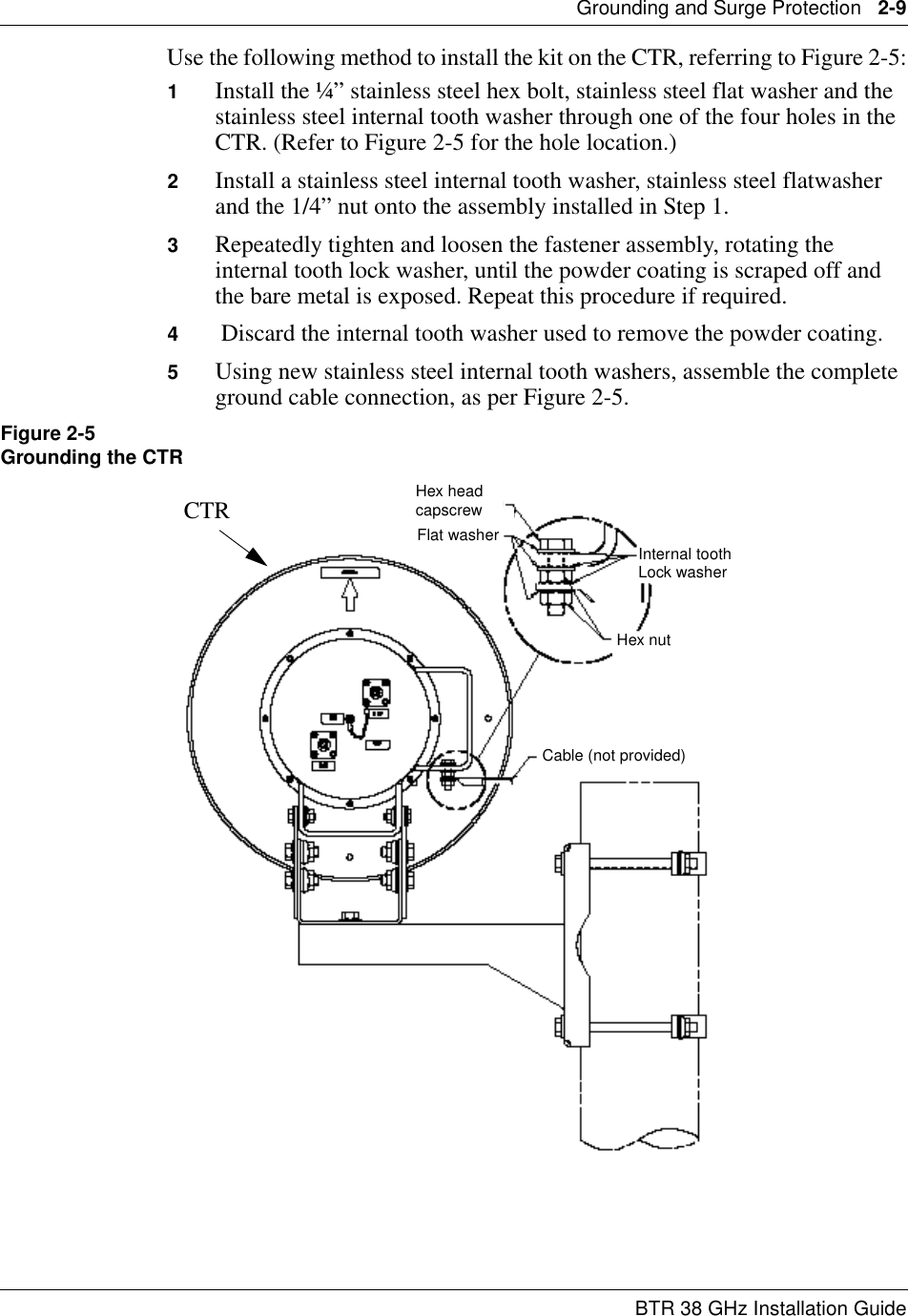
BTR User Manual
Navigation menu
Upload a User Manual
Namespaces
Wiki Guide
HTML
PDF
Info
Views
User Manual
Discussion / Help
Navigation