Northfield Telecommunications d b a Advanced Wireless Communications 04032108 UHF Radio Transceiver User Manual Owners Manual
Northfield Telecommunications, Inc. d/b/a Advanced Wireless Communications UHF Radio Transceiver Owners Manual
Contents
- 1. Owners Manual
- 2. Revised User Manual
Owners Manual

26
Industrial Radio
THANK YOU!
We are grateful for your purchase of Advanced
Wireless Communications product. We be-
lieve this easy–to-use radio will provide you
with dependable and reliable communications.
This Advanced Wireless Communications por-
table two-way radio is a precision device. Treat
it with care, and you will enjoy years of reli-
able operation.
* MODELS COVERED IN THIS MANUAL
AWR2108: UHF 450-470MHz

27
Owner’s Manual
WARNING
This radio has been tested and complies with the FCC
RF Exposure Limits for Occupational use and work-
related operations, where the operator must have
knowledge to control RF Exposure Conditions. When
transmitting, hold the radio in a vertical position at a
distance of 2.5 cm from the mouth and at least 1.5 cm
from the head and body. Do not transmit more than
50% of the duty cycle. Transmitting for more than
50% of the duty cycle can cause the FCC RF Exposure
Limits to be exceeded. Use only Advanced Wireless
Communications authorized accessories.

21
Owner’s Manual
FCC License Information
Your Advanced Wireless Communications radio operates on com-
munications frequencies which are subject to FCC(Federal Commu-
nications Commission) Rules & Regulations. FCC Rules require that
all operators using Private Land Mobile radio frequencies obtain a
radio license before operating their equipment. Application for
license must be made on FCC form 601, and schedules D, E, and G.
FAX: Forms can be obtained by fax from the FCC Fax-On-Demand
system. Call 1-202-418-0177 from your fax machine and request
document number 000600 for the form, schedules, and instructions.
MAIL: Forms can be ordered by telephone, and will be sent to you
by first class mail. Call the FCC Forms Hotline at 1-800-418-
FORM (1-800-418-3676).
INTERNET: Form 601 and instructions can be downloaded from
the FCC Forms website at:
http://www.fcc.gov/Forms/Form601/601.html
Before filling out your Form 601 application Technical Data section,
you must decide which frequency (or frequencies) you will operate
on. Refer to the frequency chart on page 26.
Questions? Call the FCC for license application questions at
1-888-CALL-FCC (1-888-225-5322).
If you have any questions, call Advanced Wireless Communications:
1-800-469-5400

22
Industrial Radio
Notices to The User
This device complies with Part 15 of the FCC Rules. Operation
is subject to the following two conditions:
(1) this device may not cause harmful interference, and
(2) this device must accept any interference received, including
interference that may cause undesired operation.
One or more of the following statements may be applicable:
FCC WARNING
This equipment generates or uses radio frequency energy.
Changes or modifications to this equipment may cause harmful
interference unless the modifications are expressly approved in
the instruction manual. The user could lose the authority to
operate this equipment if an unauthorized change or modifica-
tion is made.

23
Owner’s Manual
INFORMATION TO THE DIGITAL DEVICE
USER REQUIRED BY THE FCC
This equipment has been tested and found to comply with
the limits for a Class B digital device, pursuant to Part 15 of
the FCC Rules. These limits are designed to provide rea-
sonable protection against harmful interference in a residen-
tial installation. This equipment generates, uses and can
generate radio frequency energy and, if not installed and
used in accordance with the instructions, may cause harm-
ful interference to radio communications. However, there is
no guarantee that the interference will not occur in a par-
ticular installation. If this equipment does cause harmful
interference to radio or television reception, which can be
determined by turning the equipment off and on, the user is
encouraged to try to correct the interference by one or more
of the following measures:
• Reorient or relocate the receiving antenna.
• Increase the separation between the equipment and
receiver.
• Connect the equipment to an outlet on a circuit different
from that to which the receiver is connected.
• Consult the dealer for technical assistance.

24
Industrial Radio
SAFETY INFORMATION:
Your wireless portable two-way radio has been designed using
a low power transmitter.
When the PTT switch is pressed, the radio generates radio
frequency (RF) electromagnetic energy (EME). This radio is
designed to comply with the FCC Report and Order
FCC 96-326 (August, 1996).
CAUTION
• Do not transmit for more than 50% of the total operating
time. Transmitting for over 50% of the operating time may
exceed the FCC RF exposure compliance requirements.
Transmission occurs while you are pressing the PTT switch
and is confirmed by the LED that lights red whil etransmit-
ting.
• To transmit, speak into the microphone in your normal voice
while holding the radio upright and keep the antenna at least
2 inches (5 cm) from your head and body.
• When using a headset, ensure that the antenna is at least 2
inches (5 cm) away from your body whenever you are
transmitting.
• Use only Advanced Wireless Communications genuine
accessories. Unauthorized modifications, or attachments may
damage the transceiver and violate FCC rules and regulations.

25
Owner’s Manual
User Safety Information
PLEASE READ THIS IMPORTANT INFORMATION
BEFORE USING YOUR Advanced Wireless Communications
PORTABLE TWO-WAY RADIO.
•Only qualified technicians are allowed to maintain this product.
•To avoid electromagnetic interference, turn off your radio in
places where posted notices instruct you to do so. Hospitals
or health care facilities may be using equipment that is
sensitive to external RF energy. When travelling on aircraft,
turn off your radio when the airline crew instructs you to do
so.
•When in vehicles equipped with an air bag, do not place a
portable radio in the airbag deployment area.
•Turn off your radio prior to entering any area with a
potentially explosive atmosphere. Do not remove, install, or
charge batteries in such areas.
•To avoid possible interference with blasting operations, turn
off your radio when you are near electrical blasting caps.
•Do not use any portable radio that has a damaged antenna. If
a damaged antenna comes into contact with your skin, a
minor burn may result.
•Do not expose the radio to direct sunlight for long periods of
time. Do not place the radio in direct contact with any heating
source.

28
Industrial Radio
CONTENTS
Product Inspection........................................................................ 1
Battery Charging Information................................................. 2
Accessory Information ................................................................ 3
Battery........................................................................................ 3
Antenna ...................................................................................... 3
Belt Clip...................................................................................... 4
Getting Started.............................................................................. 5
LCD Display ................................................................................... 8
Basic Operations .......................................................................... 9
Features ......................................................................................... 10
Monitor .................................................................................... 10
Channel Scan ............................................................................ 10
Priority Channel Scan............................................................. 11
Scan Revert Channel ............................................................... 11
Selectable CTCSS/CDCSS ........................................................ 11
Selectable Squelch Level ......................................................... 13
High/Low Power ...................................................................... 13
Key Lock.................................................................................. 1 3
Time Out Timer(TOT) .......................................................... 14
Battery Save ............................................................................. 14
Low Battery Alert ................................................................... 15
Busy Channel Lockout............................................................ 15
Backlight .................................................................................. 15
Troubleshooting Guide ............................................................. 16
Optional Accessories ................................................................. 16
Care and Cleaning .................................................................... 17
CTCSS/CDCSS Table ................................................................ 18
Frequency Chart ......................................................................... 20

1
Owner’s Manual
Product Inspection
Thank you for your purchase of Advanced Wireless Communi-
cations portable two-way radio model: AWR2108. Before use,
please inspect the product as follows.
First check the shipping carton for any signs of damage. If any
damage has occurred, please contact your dealer immediately.
Confirm the supplied product against the packing slip to assure
accuracy.
Available Accessories
Part number Item Qty.(pcs)
Antenna* 1
Adapter 1
Li-TON Battery 1
Belt Clip 1
Owner’s Manual 1
Charger cup 1
*Notes: Antenna mark: white.
2
Industrial Radio
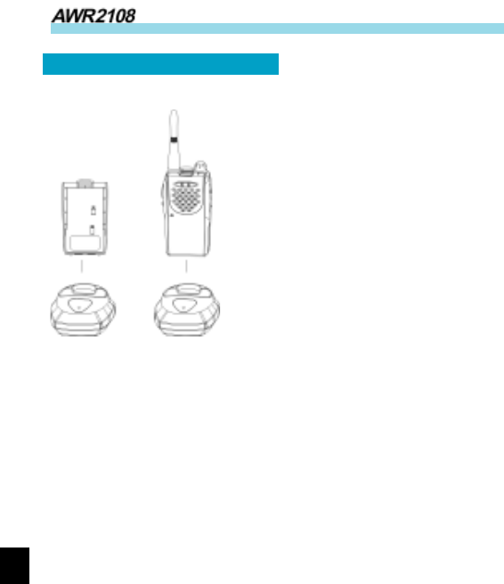
Standard Charger
1. Insert the radio and battery or
battery alone into the charging cup.
Charging begins and the red LED
will light continuously. When the
charging cycle is complete, the red
LED will change to green. Charging
time is less than 2.5 hours.
2. After the battery is fully
charged, the charger will shut off
automatically.
3. A flashing red LED indicates a defective battery. This can be
caused by an old battery or a battery defect. Contact your dealer
for instructions.
Notes:
* Batteries should be charged in a dry environment at room
temperature.
* If the battery cannot reach normal capacity after charging,
you will need replace the battery.
* Do not short out the battery terminals or dispose of the
battery by fire.
Battery Charging Information
3
Owner’s Manual
Accessory Information
nn
nn
n
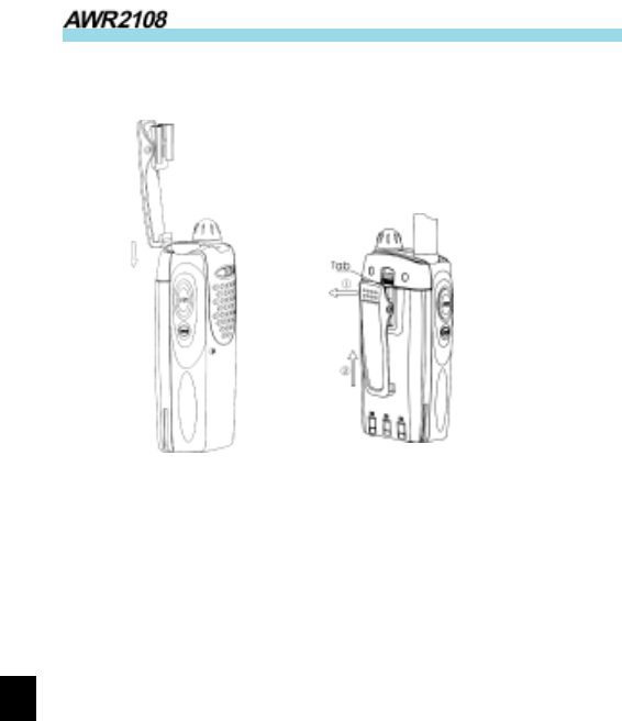
Battery
Attaching the Battery (See figure)
1.Insert the tabs, at the bottom of the battery,
into the slots at the bottom of the radio
chassis.
2.Press the top of the battery towards the
radio until a click is heard.
Removing the Battery (See figure)
1.Turn off the radio.
2. Push the battery latch on the back panel,
towards the top of the radio.
3.Pull the top of the battery away from the
radio chassis, and lift the battery from the
radio.
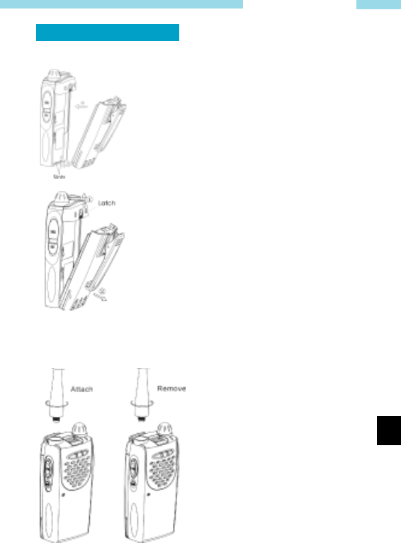
n Antenna
Attaching the Antenna (See
figure)
1. Align the threaded end of the
antenna with the radio’s antenna
connector.
2.Turn the antenna clockwise to
tighten.
Removing the Antenna(See figure)
Turn the antenna counter-clock-
wise until you can remove it.
4
Industrial Radio
nn
nn
n
Belt Clip
Attach Remove
Attaching the Belt Clip (See figure)
1. Align the grooves of the belt clip with those of the battery.
2. Press the belt clip down until a click is heard.
Removing the Belt Clip (See figure)
1. Pry the belt clip tab away from the battery.
2. Slide the belt clip upwards to remove it.
5
Owner’s Manual
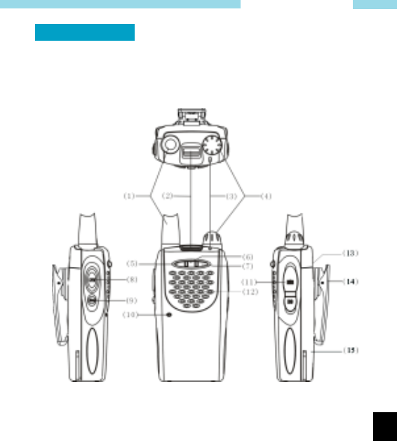
Getting Started
1. Antenna
Used to receive or transmit signals.
2. LCD
Displays operation status of the radio.

6
Industrial Radio
3. LED indicator
In transmit mode, the red LED will turn on. In receive mode,
the green LED will turn on. A flashing red LED indicates
that the battery is low.
4. POWER/VOL Knob
Rotate the volume control clockwise to turn the unit on,
fully counter clockwise to turn the unit off. Increase or
decrease volume by adjusting the volume control accordingly.
5. Down key
Adjust the channel downwards.
6. SCAN key
Press the scan key to activate the scan mode. When the
radio detects properly coded activity on a channel, it will
stop scanning and listen to that channel.
7. Up key
Adjust the channel upwards.
8. PTT button
To transmit, press and hold PTT button. To receive,release
PTT button.
9. MONI button
In receive mode, press the MONI key to monitor other
activity on your selected channel .

7
Owner’s Manual
10. Microphone
When transmitting, speak into the microphone holding the
radio 2-4 inches from your mouth.
11. jack
Used to connect external earphone/microphoneaccessories.
12. Speaker
Listen to received audio.
13. Battery latch
Used to fasten and remove the battery.
14. Belt clip
Used to clip radio on your belt.
15. Battery pack
8
Industrial Radio
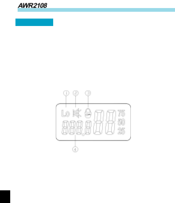
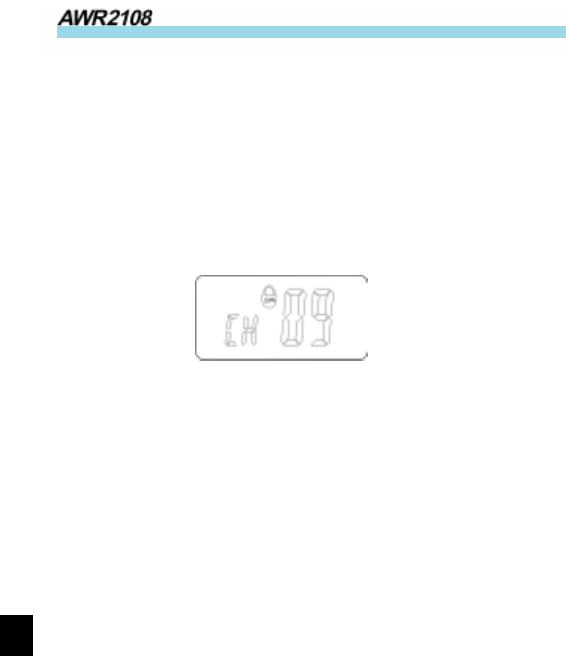
LCD Display
1. Appears when the transmit power of the current channel is set
for low power.
2. Appears when the dealer disables the radio’s speaker. (Must
use audio accessory to operate.)
3. Appears when the keys are locked.
4. Display the current channel number.

9
Owner’s Manual
Basic Operations
• To Turn On the Radio
Turn the POWER/VOL knob clockwise until a click is heard.
• To Receive
1. Press UP or DOWN key to select the desired channel.
2. Turn POWER/VOL knob to adjust the volume. Pressing the
MONI key will provide noise so that the volume can be
adjusted accordingly.
Now if the radio receives a signal with CTCSS/CDCSS match-
ing with that set in the radio, the speaker will output audio.
• To Transmit
1. Press the UP or DOWN key to select the desired channel.
2. To avoid interfering with other users, press the MONI key to
monitor activities on your channel and make sure the channel
is idle before transmitting.
3. To transmit, press and hold the PTT button, speak clearly
into the microphone with the radio 2 to 4 inches away from
your mouth. To receive, release the PTT button. When the
PTT button is pressed, the red LED will ight until the PTT
button is released or until the transmit time out timer expires.

10
Industrial Radio
Features
n Monitor
Press the MONI button to monitor any activity on the channel.
Wait for this activity to clear before transmitting.
n Channel Scan
Channel scan is set to monitor desired activities on all channels in
scan list. When channel scan is enabled, the radio will automati-
cally scan all channels in scan list until activity is detected on a
channel. The scanning will then stop and the receive audio will
be heard.When scanning stops on an active channel, it will restart
in the preset restart mode that is set by the dealer. Scan restart
mode can be either Time operated scan or Carrier operated scan.
1. Time Operated Scan
If scanning stops on an active channel, and continues to listen for
a preset period (the time is preset by the dealer), it will begin
scanning other channels even if there is still activity on the channel.
2. Carrier Operated Scan
Scan will lock in on the busy channel until there is no activity.
Channel Scan Operations
1. Press SCAN key
Scan starts from the current channel and then scrolls all
selected channels in sequence.
2. Press UP or DOWN key to change channel scan sequence.
Press the UP key; radio skips the current channel and scans
other selected channels in ascending order; press the DOWN

11
Owner’s Manual
key; radio skips the current channel and scans other se-
lected channels in descending order.
3. Press SCAN key again, scan stops.
4. Adding or deleting a channel in/from the scan list. The dealer
can add or delete a channel in/from the scan list. Only chan-
nels in the scan list can be scanned.
n Priority Channel Scan
If your dealer has set a priority channel, when radio scans non-
priority channels, it will periodically sample the priority channel.
If desired activity is detected on the priority channel, it will
switch to the priority channel for communications.
n Scan Revert Channel
The scan revert channel feature allows you to transmit on the
proper channel while initiating a call during channel scan. Press
[PTT] button, radio stops scanning and transmits on the revert
channel. This feature is set by the dealer.
n Selectable CTCSS/CDCSS
CTCSS/CDCSS feature is used to avoid receiving unwanted
signals on the same channel. When CTCSS/CDCSS is enabled,
the radio only allows audio with the same CTCSS/CDCSS code
to activate the speaker. If CTCSS/CDCSS is disabled, the radio
will hear all calls on the same channel. When the dealer allows
CTCSS/CDCSS to be selectable by the end user, the operations
are as follows:
Press the [UP] key while holding down the [MONI] key to enter
12
Industrial Radio
CTCSS/CDCSS set mode.In this mode, press [UP] or [DOWN]
to select CTCSS/CDCSS.
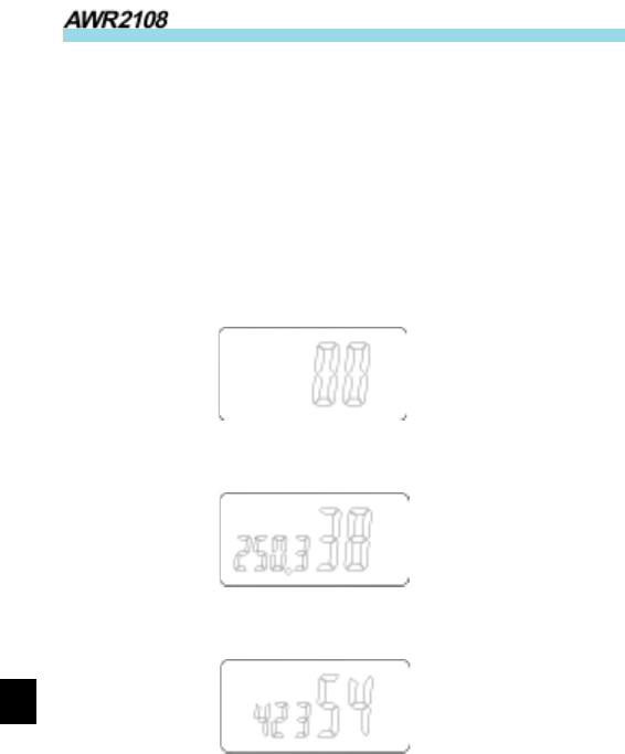
Press [SCAN], LCD display toggles between OFF/CTCSS/
CDCSS/-CDCSS:
CTCSS/CDCSS OFF: 00
CTCSS: 01— 38
CDCSS: 01— 83
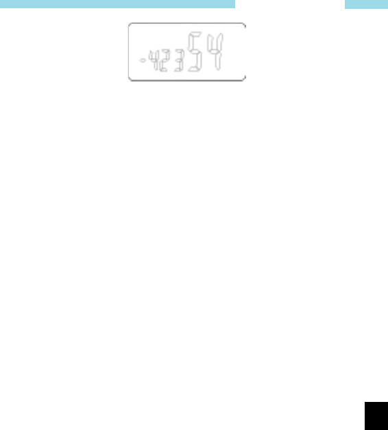
-CDCSS: -01— -83
OFF
CTCSS
CDCSS
13
Owner’s Manual
-CDCSS
Please refer to CTCSS/CDCSS table.
Press [UP] while holding down [MONI] to exit CTCSS/CDCSS
mode.
Note: Though CTCSS/CDCSS feature can prevent you from
receiving unwanted signals, it doesn’t mean your calls are
absolutely private.
n Selectable squelch level
If this feature is enabled by the dealer, then
Press the [DOWN] key while holding down the [MONI] key to
enter squelch level set mode. In this mode, press [UP]/[DOWN]
to select the level 0—9.
Press [PTT] or [MONI] or [SCAN] to exit the mode.
n High/Low power
If this feature is enabled by the dealer, then
While holding down [PTT], press [MONI] to toggle the power
of the current channel between high and low.
When the power is low, “Lo” will be displayed on LCD.
n Key lock
The key lock feature is designed to avoid accidental pressing of
keys. If this feature is enabled by the dealer.
14
Industrial Radio
The operation procedures are as follows:
1. Press [SCAN] while holding down [MONI] to lock keys.
When keys are locked, [UP],[DOWN] and [SCAN] keys
are inoperable, but [PTT] and [MONI] keys will still
function.
2. Press [SCAN] while holding down [MONI] to unlock keys.
3. lock symbol appears on LCD:
n Time Out Timer (TOT)
Time Out Timer is to prevent user from transmitting on the same
channel for extended periods of time. This also protects the radio
from damage caused by accidental transmissions.
If transmission exceeds the preset time, (the TOT time can be
preset by the dealer), the radio will stop transmitting and return
to the receive mode. Alert beeps will sound to indicate the halt in
transmission. Releasing the PTT button will cause the beeps
stop.
n Battery Save
While no activity is on channel and no operation is performed for
5 seconds, the Battery Save feature will automatically be switched
on to reduce power consumption. When a signal is received or an
operation is performed, the Battery Save feature is automatically
switched off.

15
Owner’s Manual
nn
nn
n
Low Battery Alert
When the battery voltage is lower than preset value, red LED
will flash.
When the battery voltage becomes too low, red LED will flash
and beeps sound. When you try to transmit at this time, it is
forbidden and beeps sound continuously.
You need to replace or charge the battery.
n Busy Channel Lockout
If the selected channel is set for busy channel lock out by your
dealer, you cannot transmit when there is activity on that channel.
n Backlight
This feature can be enabled by the dealer.
When this feature is enabled, pressing any key except the PTT
will illuminate the display. The display will stay lit for 5 seconds.

16
Industrial Radio
Troubleshooting Guide
Please check the following items before requesting service.
1. Review operation procedures.
2. Replace or recharge the battery.
3. If reception is poor, check the antenna to make sure it is
undamaged and operating in a vertical position.
4. Try another location with fewer obstructions.
5. If you cannot communicate with your group members, make
sure you are using the same frequency and CTCSS/CDCSS.
6. If you hear other conversations on your channel, change
your CTCSS/CDCSS. Remember to change CTCSS/CDCSS
of your other group members.
Optional Accessories
• Earphone
• Leather Case
• Headset (many options)
• Speaker mic

17
Owner’s Manual
Care and Cleaning
• Do not carry your radio by the antenna or remote microphone.
• Wipe the battery contacts with a lint-free cloth to remove
dirt, grease, or other material that may prevent good elec
trical connection.
• When not in use, keep the accessory jacks covered with the
protective cap.
• If cleaning the radio housing becomes necessary, use a cloth
or paper towel dampened with a non-abrasive cleaner. Glass
cleaner works well. Avoid using strong chemicals. DO NOT
submerge in water.
18
Industrial Radio
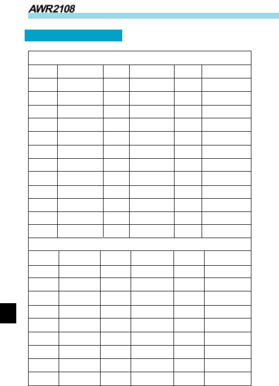
CTCSS/CDCSS Table
CTCSS
NO Freq(Hz) NO Freq(Hz) NO Freq(Hz)
00 NO TONE 13 103.5 26 162.2
01 67.0 14 107.2 27 167.9
02 71.9 15 110.9 28 173.8
04 77.0 17 118.8 30 186.2
05 79.7 18 123.0 31 192.8
06 82.5 19 127.3 32 203.5
07 85.4 20 131.8 33 210.7
08 88.5 21 136.5 34 218.1
09 91.5 22 141.3 35 225.7
10 94.8 23 146.2 36 233.6
11 97.4 24 151.4 37 241.8
12 100.0 25 156.7 38 250.3
CDCSS
NO CODE NO CODE NO CODE
01 023 29 174 57 445
02 025 30 205 58 464
03 026 31 223 59 465
04 031 32 226 60 466
05 032 33 243 61 503
06 043 34 244 62 506
07 047 35 245 63 516
08 051 36 251 64 532
09 054 37 261 65 546

19
Owner’s Manual
NO CODE NO CODE NO CODE
10 065 38 263 66 565
11 071 39 265 67 606
12 072 40 271 68 612
13 073 41 306 69 624
14 074 42 311 70 627
15 114 43 315 71 631
16 115 44 331 72 632
17 116 45 343 73 654
18 125 46 346 74 662
19 131 47 351 75 664
20 132 48 364 76 703
21 134 49 365 77 712
22 143 50 371 78 723
23 152 51 411 79 731
24 155 52 412 80 732
25 156 53 413 81 734
26 162 54 423 82 743
27 165 55 431 83 754
28 172 56 432
20
Industrial Radio
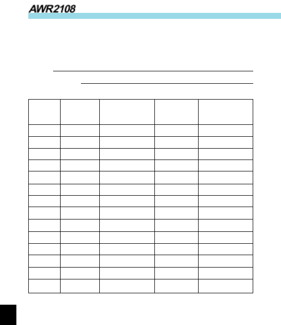
Frequency chart
Model:
Serial Number:
Channel Transmit Transmit Receive Receive
Frequency CTCSS/CDCSS Frequency CTCSS/CDCSS
1
2
3
4
5
6
7
8
9
10
11
12
13
14

29
Owner’s Manual
AWC endeavor to achieve the accuracy and completeness of this
manual, but cannot guarantee its accuracy at all times. All the
above specifications and design are subject to change by AWC
without notice.
All the reproduction and translation of this manual without
authorization of AWC is not allowed.