Northfield Telecommunications d b a Advanced Wireless Communications 04032108 UHF Radio Transceiver User Manual AWR2108 Owner s manual confirm
Northfield Telecommunications, Inc. d/b/a Advanced Wireless Communications UHF Radio Transceiver AWR2108 Owner s manual confirm
Contents
- 1. Owners Manual
- 2. Revised User Manual
Revised User Manual
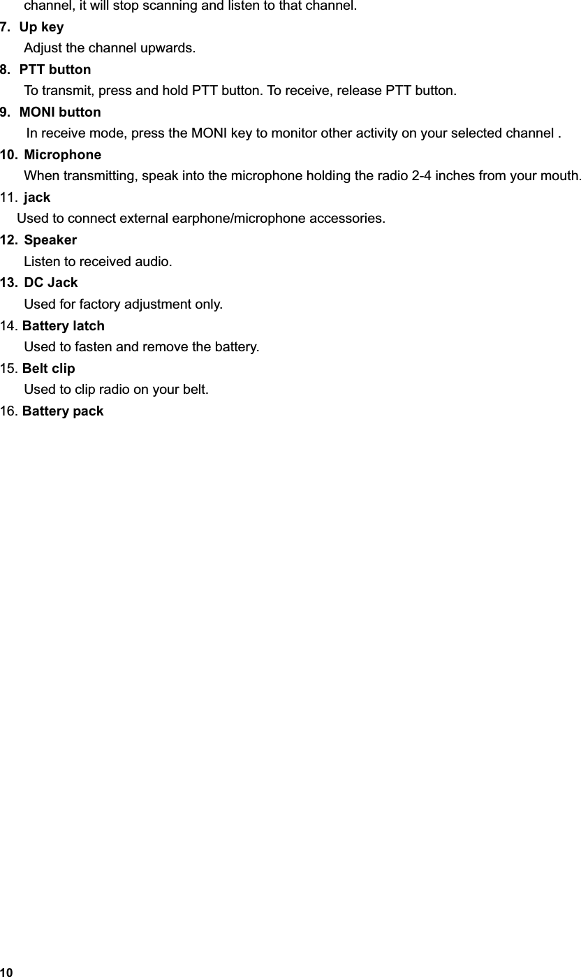
![13Features MonitorPress the MONI button to monitor any activity on the channel. Wait for this activity to clear before transmitting. Channel Scan Channel scan is set to monitor desired activities on all channels in scan list. When channel scan is enabled, the radio will automatically scan all channels in scan list until activity is detected on a channel. The scanning will then stop and the receive audio will be heard.When scanning stops on an active channel, it will restart in the preset restart mode that is set by the dealer. Scan restart mode can be either Time operated scan or Carrier operated scan. Time Operated Scan If scanning stops on an active channel, and continues to listen for a preset period (the time is preset by the dealer), it will begin scanning other channels even if there is still activity on the channel. Carrier Operated ScanScan will lock in on the busy channel until there is no activity. Channel Scan Operations 1. Press SCAN key Scan starts from the current channel and then scrolls all selected channels in sequence. 2. Press UP or DOWN key to change channel scan sequence. Press the UP key; radio skips the current channel and scans other selected channels in ascending order; press the DOWN key; radio skips the current channel and scans other selected channels in descending order. 3. Press SCAN key again, scan stops. 4. Adding or deleting a channel in/from the scan list. The dealer can add or delete a channel in/from the scan list. Only channels in the scan list can be scanned. Priority Channel ScanIf your dealer has set a priority channel, when radio scans non-priority channels, it will periodically sample the priority channel. If desired activity is detected on the priority channel, it will switch to the priority channel for communications. Scan Revert Channel The scan revert channel feature allows you to transmit on the proper channel while initiating a call during channel scan. Press [PTT] button, radio stops scanning and transmits on the revert channel. This feature is set by the dealer. Selectable CTCSS/CDCSS CTCSS/CDCSS feature is used to avoid receiving unwanted signals on the same channel. When CTCSS/CDCSS is enabled, the radio only allows audio with the same CTCSS/CDCSS code to activate the speaker. If CTCSS/CDCSS is disabled, the radio will hear all calls on the same channel.When the dealer allows CTCSS/CDCSS to be selectable by the end user, the operations are as follows:](https://usermanual.wiki/Northfield-Telecommunications-d-b-a-Advanced-Wireless-Communications/04032108.Revised-User-Manual/User-Guide-371400-Page-13.png)
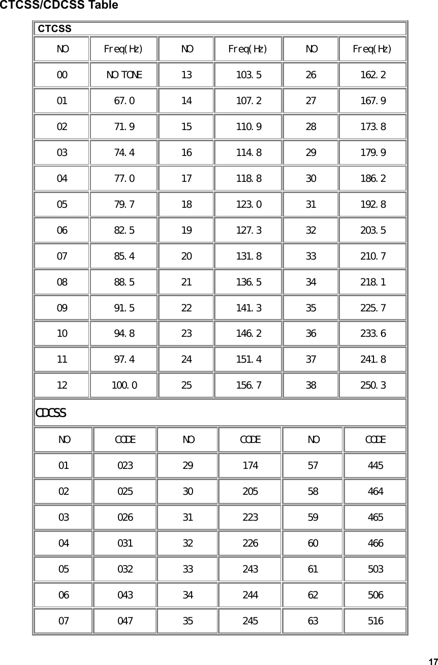
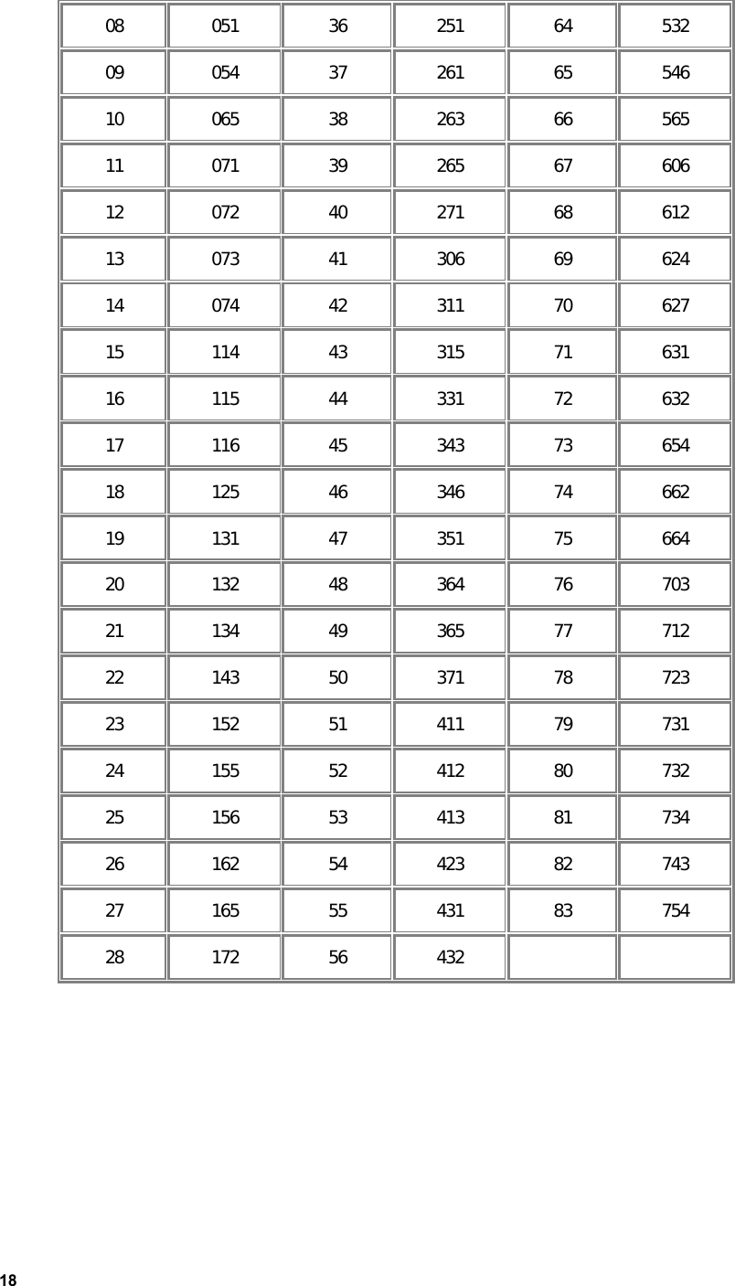
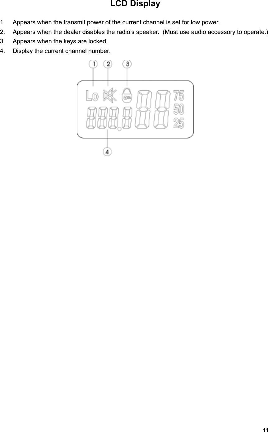
![14Press the [UP] key while holding down the [MONI] key to enter CTCSS/CDCSS set mode. In this mode, press [UP] or [DOWN] to select CTCSS/CDCSS.Press [SCAN], LCD display toggles between OFF/CTCSS/CDCSS/-CDCSS: CTCSS/CDCSS OFF: 00 CTCSS: 01 38 CDCSS: 01 83 -CDCSS: -01 -83 OFF CTCSS CDCSS -CDCSS Please refer to CTCSS/CDCSS table. Press [UP] while holding down [MONI] to exit CTCSS/CDCSS mode.Note: Though CTCSS/CDCSS feature can prevent you from receiving unwanted signals; it doesn’t mean your calls are absolutely private. Selectable squelch level If this feature is enabled by the dealer, then Press the [DOWN] key while holding down the [MONI] key to enter squelch level set mode. In this mode, press [UP]/[DOWN] to select the level, 0 9.Press [PTT] or [MONI] or [SCAN] to exit the mode. High/Low power If this feature is enabled by the dealer, then While holding down [PTT], press [MONI] to toggle the power of the current channel between high and low. When the power is low, “Lo” will be displayed on LCD. Key lockThe key lock feature is designed to avoid accidental pressing of keys. If this feature is enabled by the dealer, The operation procedures are as follows:1, Press [SCAN] while holding down [MONI] to lock keys. When keys are locked, [UP],[DOWN] and [SCAN] keys are inoperable, but [PTT] and [MONI] keys will still function.](https://usermanual.wiki/Northfield-Telecommunications-d-b-a-Advanced-Wireless-Communications/04032108.Revised-User-Manual/User-Guide-371400-Page-14.png)
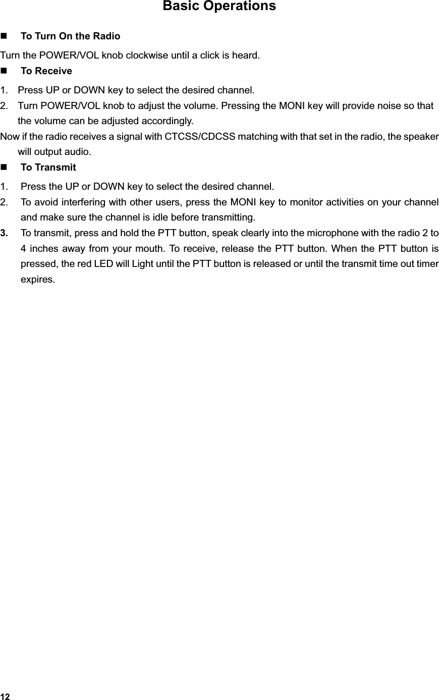
![152, Press [SCAN] while holding down [MONI] to unlock keys. 3, lock symbol appears on LCD: Time Out Timer (TOT) Time Out Timer is to prevent user from transmitting on the same channel for extended periods of time. This also protects the radio from damage caused by accidental transmissions. If transmission exceeds the preset time, (the TOT time can be preset by the dealer), the radio will stop transmitting and return to the receive mode. Alert beeps will sound to indicate the halt in transmission. Releasing the PTT button will cause the beeps stop. Battery Save While no activity is on channel and no operation is performed for 5 seconds, the Battery Save feature will automatically be switched on to reduce power consumption. When a signal is received or an operation is performed, the Battery Save feature is automatically switched off. Low Battery Alert When the battery voltage is lower than preset value, red LED will flash. When the battery voltage becomes too low, red LED will flash and beeps sound. When you try to transmit at this time, it is forbidden and beeps sound continuously. You need to replace or charge the battery. Busy Channel Lock Out If the selected channel is set for busy channel lock out, by your dealer, you cannot transmit when there is activity on that channel. If you press the PTT button, the radio will sound beeps and will stay in the receive mode. BacklightThis feature can be enabled by the dealer. When this feature is enabled, pressing any key except the PTT will illuminate the display. The display will stay lit for 5 seconds.](https://usermanual.wiki/Northfield-Telecommunications-d-b-a-Advanced-Wireless-Communications/04032108.Revised-User-Manual/User-Guide-371400-Page-15.png)