Northfield Telecommunications d b a Advanced Wireless Communications 07161688P Portable FM UHF PTT Radio Transceiver User Manual AWR1688 Owner manual
Northfield Telecommunications, Inc. d/b/a Advanced Wireless Communications Portable FM UHF PTT Radio Transceiver AWR1688 Owner manual
Contents
- 1. USERS MANUAL
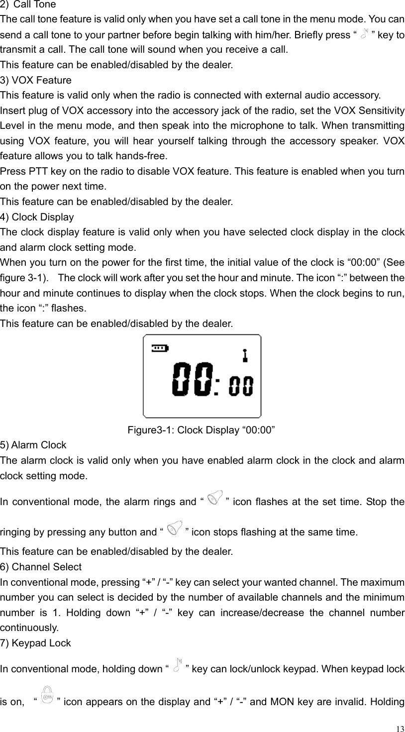
- 2. SERVICE MANUAL
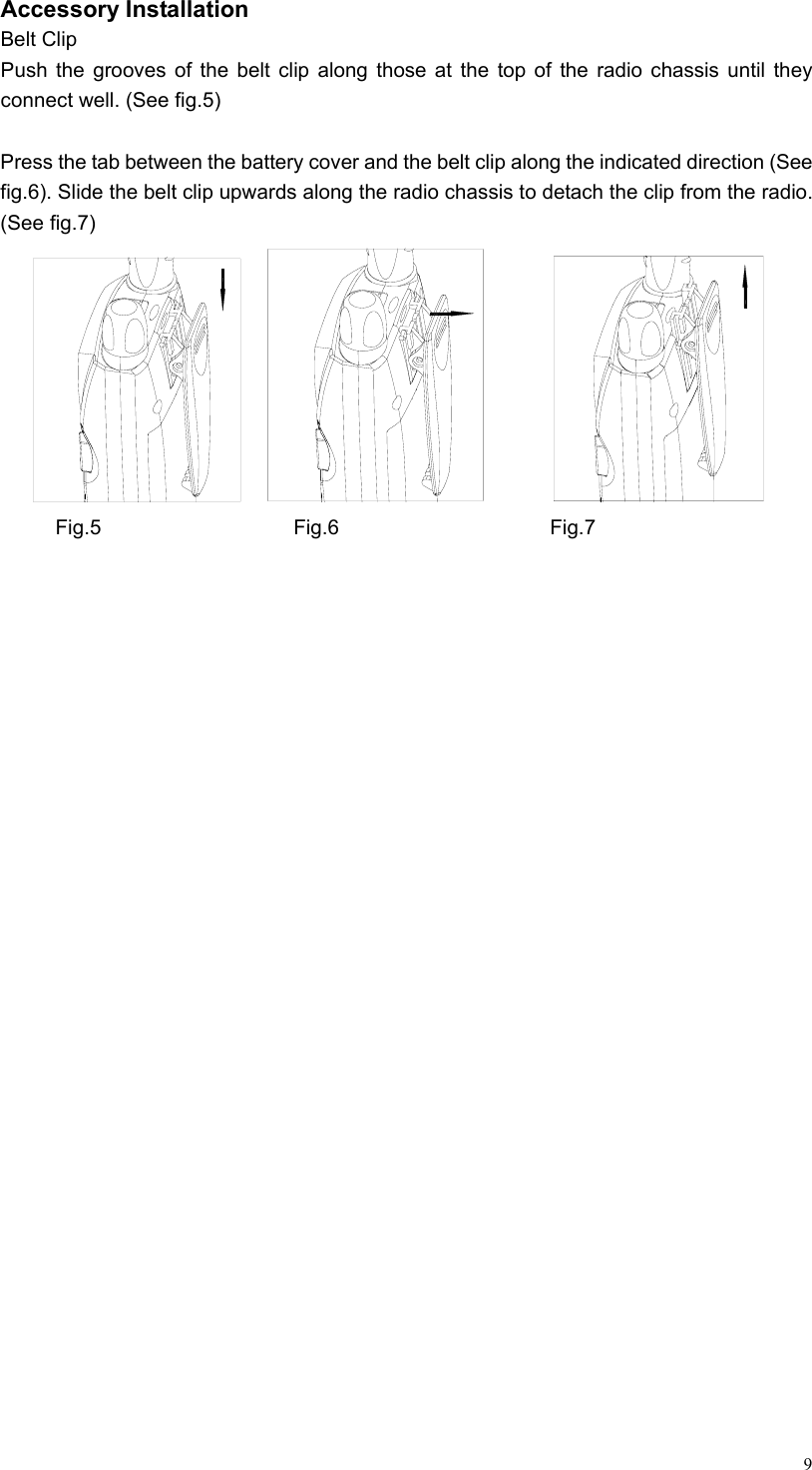
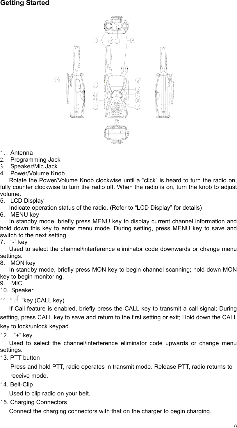
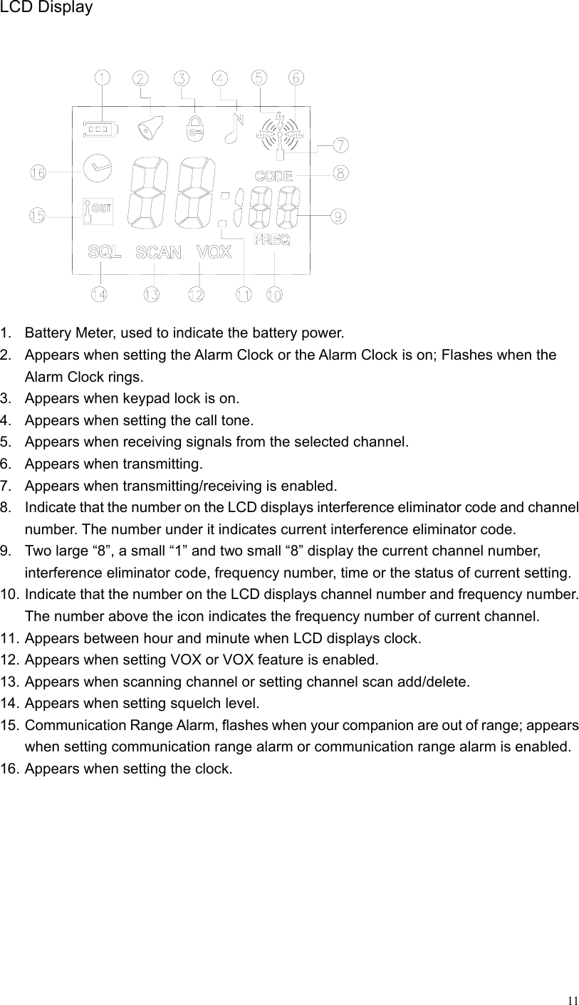
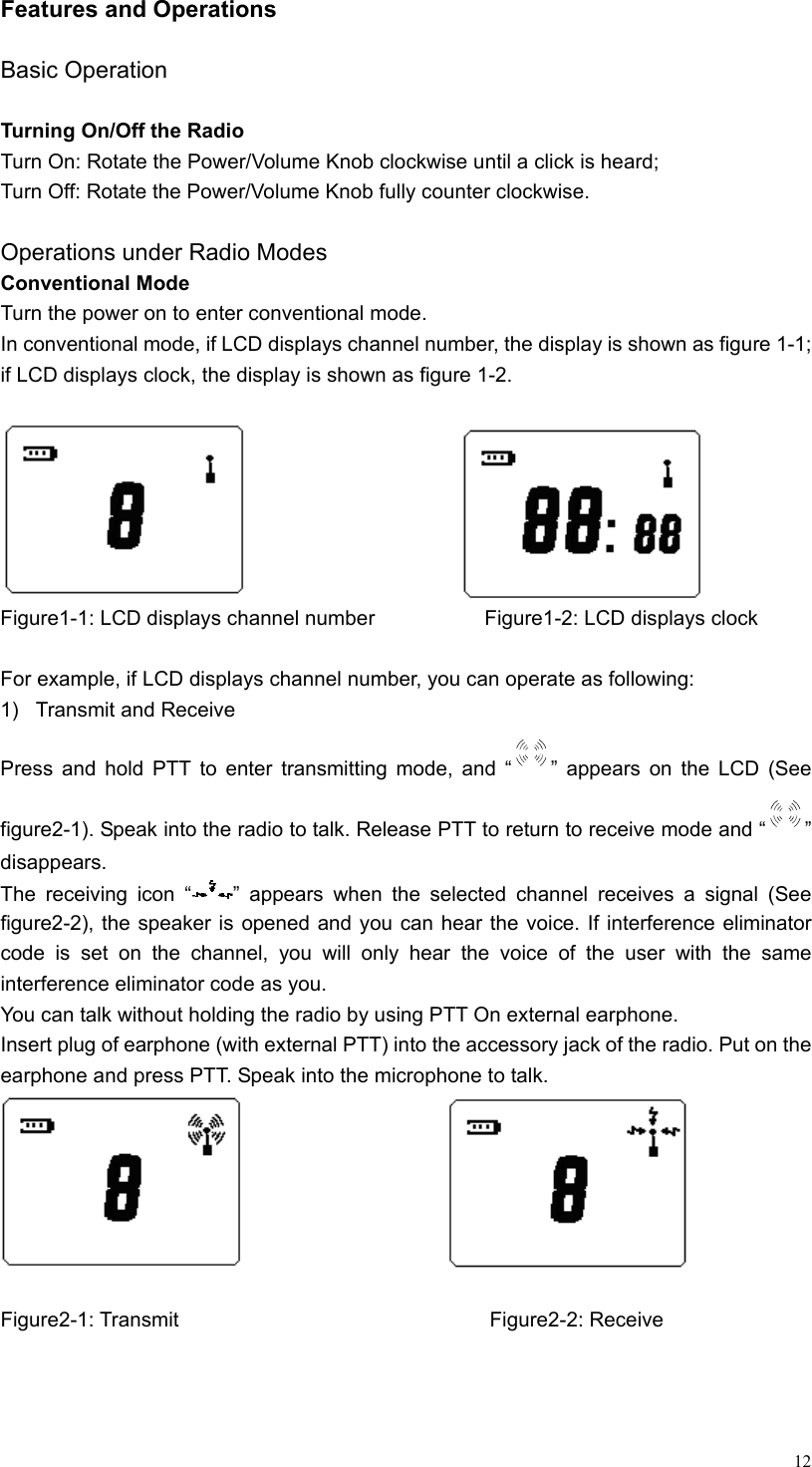
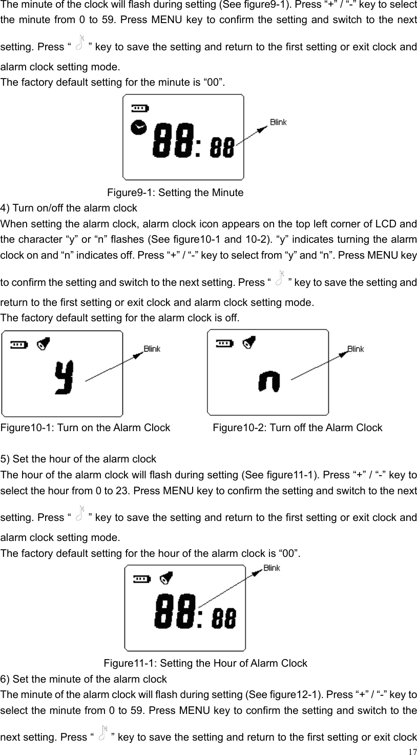
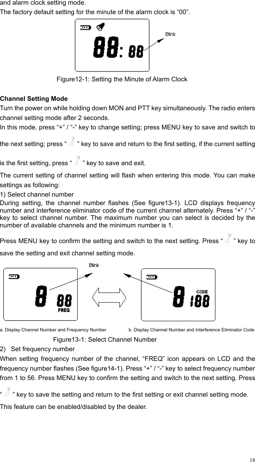
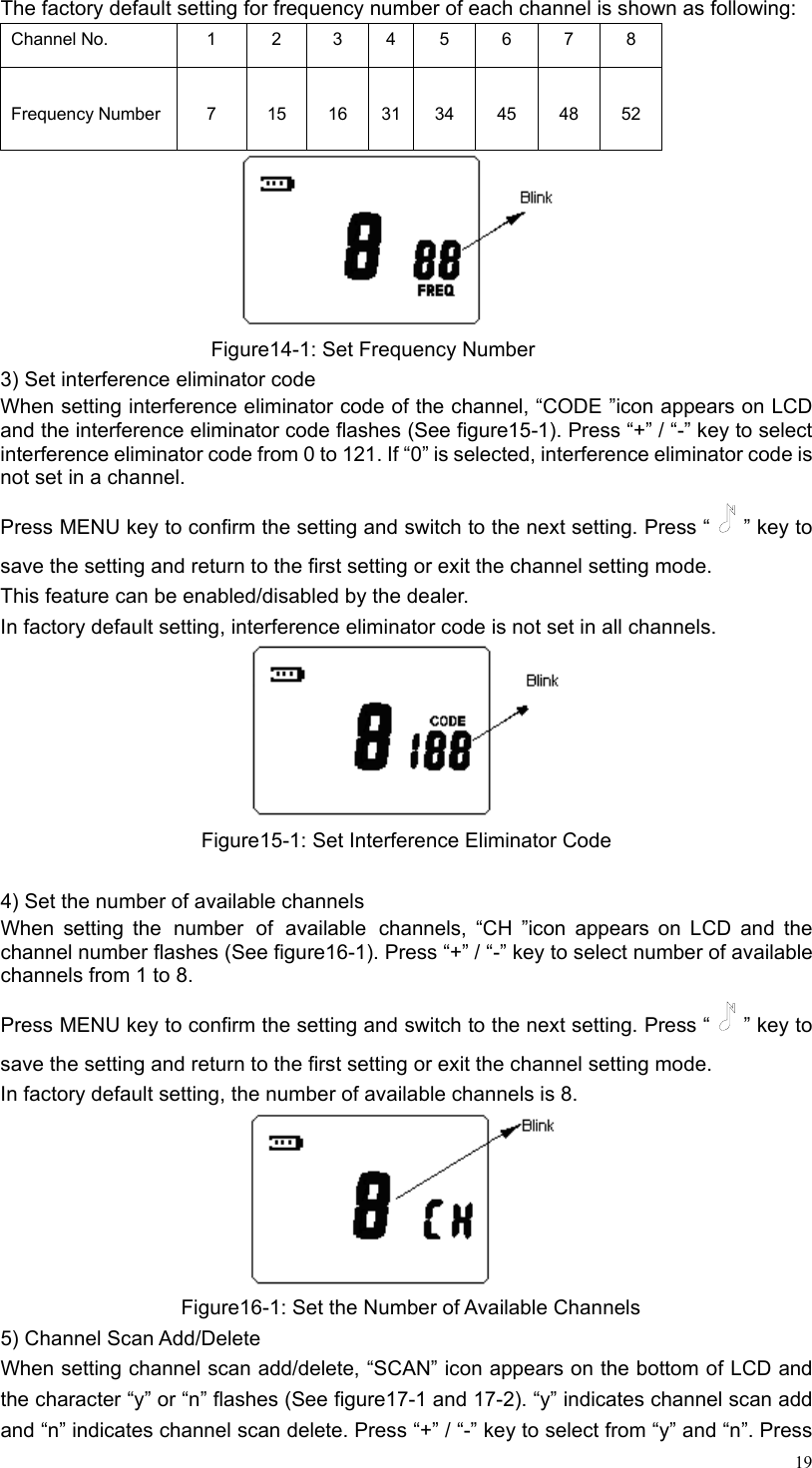
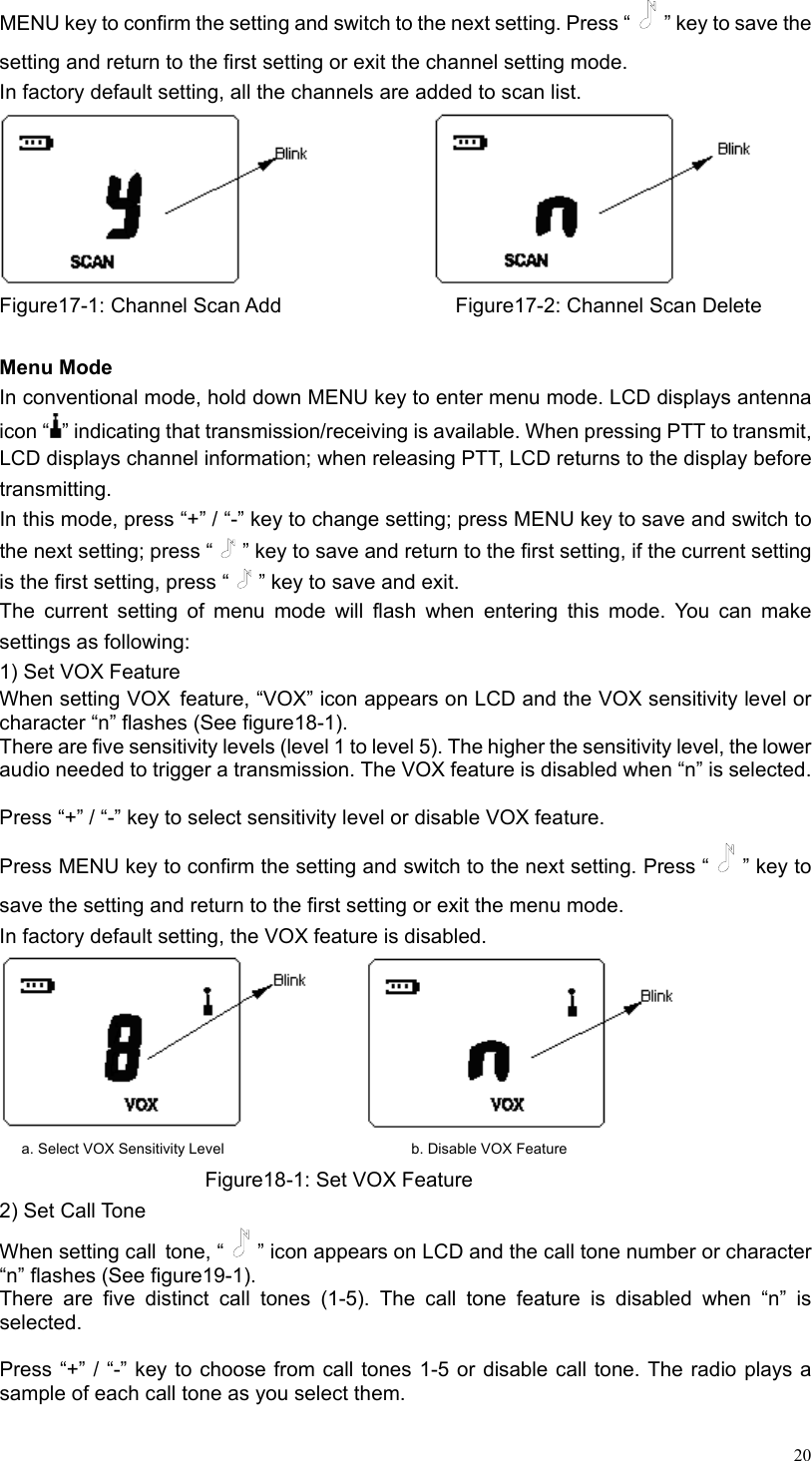
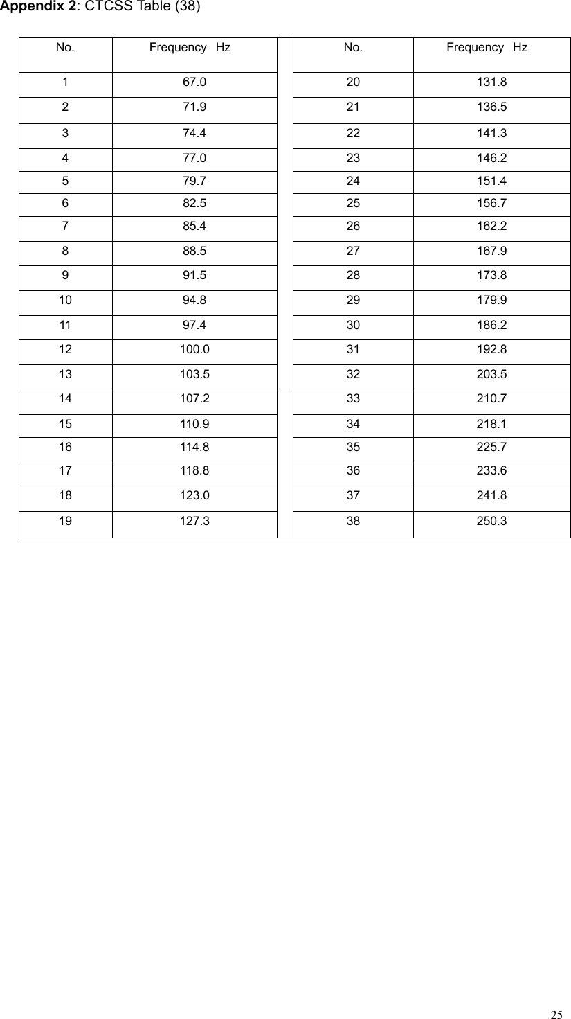
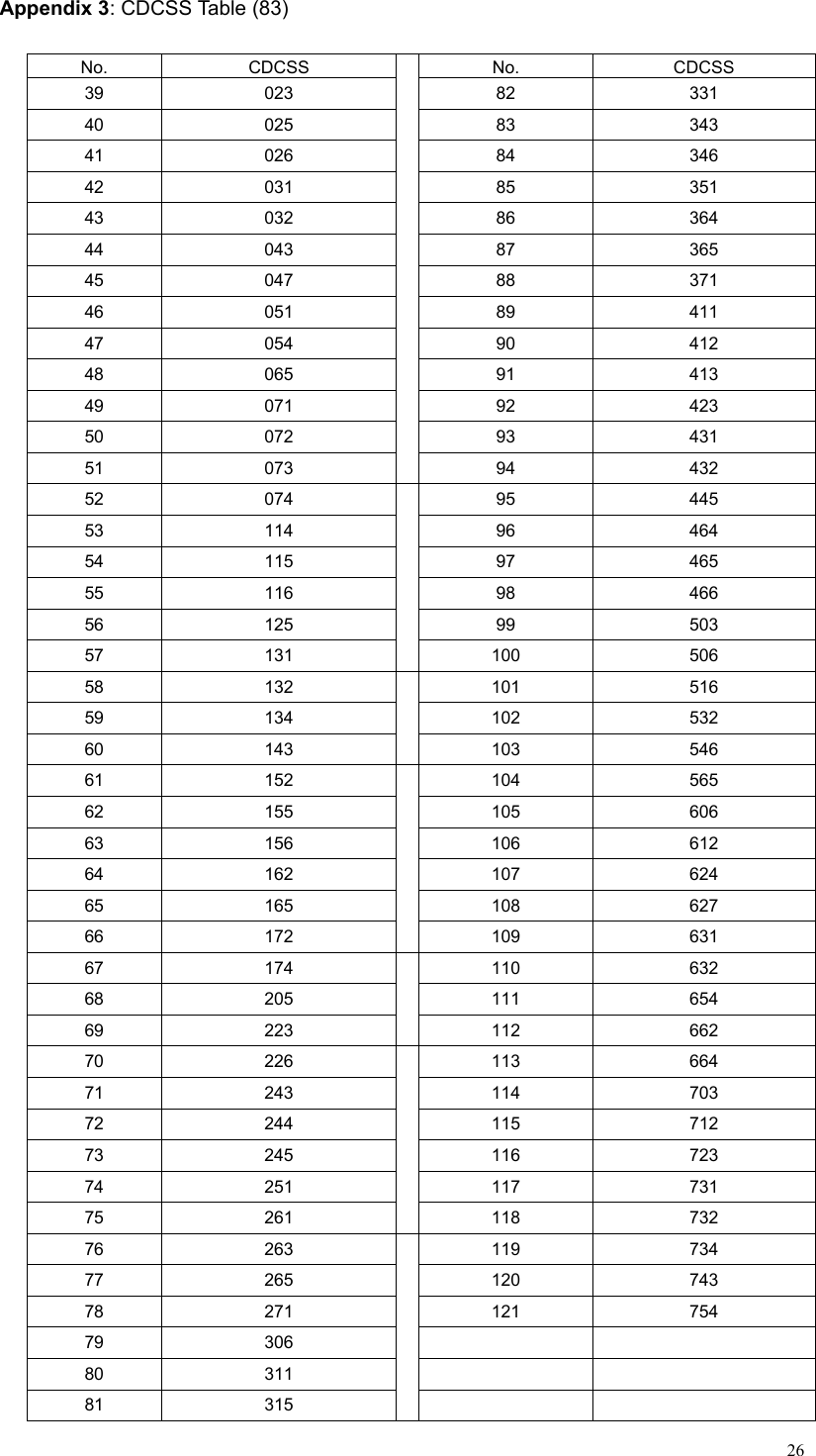
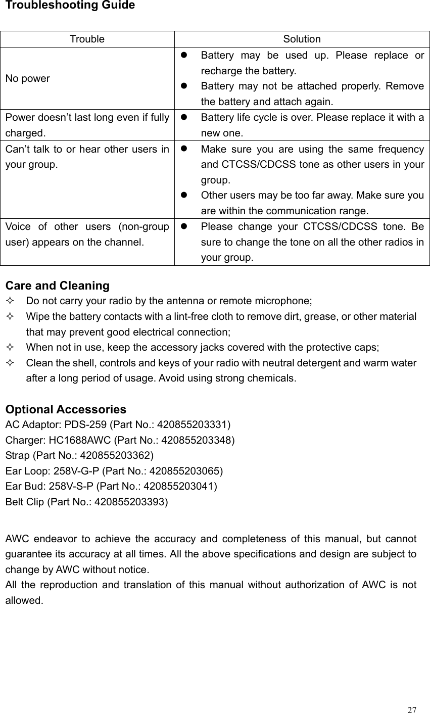
USERS MANUAL