Northfield Telecommunications d b a Advanced Wireless Communications 07161688P Portable FM UHF PTT Radio Transceiver User Manual AWR1688 Owner manual
Northfield Telecommunications, Inc. d/b/a Advanced Wireless Communications Portable FM UHF PTT Radio Transceiver AWR1688 Owner manual
Contents
- 1. USERS MANUAL
- 2. SERVICE MANUAL
USERS MANUAL
1
THANK YOU!
We are grateful for your purchase of AWC product. We believe this easy–to-use
radio will provide you with dependable and reliable communications. This AWC
portable two-way radio is a precision device. Treat it with care, and you will enjoy
years of reliable operation.
2
Product Safety and RF Exposure for Portable Two-Way Radios
Compliance with RF Energy Exposure Standards
NOTICE: This radio is intended for use in occupational/controlled applications where users have
been made aware of the potential for exposure and can exercise control over their exposure. This
radio device is NOT authorized for general population, consumer or similar use.
BEFORE USING THIS RADIO, READ THE TRAINING MATERIAL BELOW WHICH
CONTAINS IMPORTANT OPERATING INSTRUCTIONS FOR SAFE USAGE AND RF
ENERGY AWARENESS AND CONTROL INFORMATION FOR COMPLIANCE WITH RF
ENERGY EXPOSURE LIMITS IN APPLICABLE NATIONAL AND INTERNATIONAL
STANDARDS.
Federal Communication Commission (FCC) Regulations
The FCC has established limits for safe exposure to radio frequency (RF) emissions from
portable two-way radios. The FCC requires manufacturers to demonstrate compliance with
RF exposure limits before portable two-way radios can be marketed in the U.S. When
two-way radios are approved for occupational/controlled environment exposure limits, the
FCC requires users to be fully aware of, and exercise control over, their exposure.
Awareness and control of RF exposure can be accomplished by the use of labels, or by
education and training through appropriate means, such as information and instructions in
user manuals or safety booklets. Your Advanced Wireless two-way radio has an RF
exposure information label in the battery compartment. The training material below
includes useful information about RF exposure and helpful instructions on how to control
your RF exposure.
Your Advanced Wireless two-way radio is designed and tested to comply with a number of
national and international standards and guidelines (listed below) regarding human
exposure to RF electromagnetic energy. In terms of measuring RF energy for compliance
with FCC exposure guidelines, your radio radiates measurable RF energy only while it is
transmitting (during talking), not when it is receiving (listening) or in standby mode.
Compliance and Control Guidelines and Operating Instructions for Portable
Two-Way Radios
To control your exposure and ensure compliance with the occupational/controlled
environment exposure limits, always adhere to the following procedures:
* Transmit no more than 50% of the time. To transmit (talk), push the Push-To-Talk (PTT)
button. To receive calls, release the PTT button. Transmitting 50% of the time or less is
important since the radio generates measurable RF energy exposure only when
transmitting (in terms of measuring standards compliance).
*Hold the radio in a vertical position in front of the face with the microphone positioned at
least one inch (2.5 cm) away from the lips. Keeping the radio at the proper distance is
important since RF exposure decreases with increasing distance from the antenna.
*
For body-worn operation, always use the radio with the AWC Belt-Clip Part No.:
420855203393. AWC-approved accessories, antennas, and device combinations have
been tested and comply with the occupational/controlled environment RF exposure limits.
The use of non–AWC approved accessories may result in exposure levels that exceed the
RF exposure limits for the occupational/controlled environment.

3
* If you are not using a body-worn accessory and are not using the radio held in front of the
face, ensure the radio is kept a minimum of 0.7 cm from the body when transmitting.
Keeping the radio at a proper distance is important since RF exposure decreases with
increasing distance from the antenna.
FCC license Information
Your Advanced Wireless Communications radio operates on communications frequencies
which are subject to FCC (Federal Communications Commission) Rules & Regulations.
FCC Rules require that all operators using Private Land Mobile radio frequencies obtain a
radio license before operating their equipment. Application for license must be made on
FCC form 601, and schedules D, E, and G.
FAX: Forms can be obtained by fax from the FCC Fax-On-Demand system. Call
1-202-418-0177 from your fax machine and request document number 000600 for the form,
schedules, and instructions.
MAIL: Forms can be ordered by telephone, and will be sent to you by first class mail. Call
the FCC Forms Hotline at 1-800-418-FORM (1-800-418-3676).
INTERNET: Form 601 and instructions can be downloaded from the FCC Forms website at:
http://www.fcc.gov/Forms/Form601/601.html
Before filling out your Form 601 application Technical Data section, you must decide which
frequency (or frequencies) you will operate on. Refer to the frequency chart on page 24.
Questions? Call the FCC for license application questions at
1-888-CALL-FCC (1-888-225-5322).
If you have any questions, call Advanced Wireless Communications:
1-800-475-5852
Notices to The User
This device complies with Part 15 of the FCC Rules. Operation is subject to the following
two conditions:
(1) this device may not cause harmful interference, and
(2) this device must accept any interference received, including interference that may
cause undesired operation.
One or more of the following statements may be applicable:
FCC WARNING
This equipment generates or uses radio frequency energy. Changes or modifications to this
equipment may cause harmful interference unless the modifications are expressly approved
in the instruction manual. The user could lose the authority to operate this equipment if an
unauthorized change or modification is made.

4
SAFETY INFORMATION:
Your wireless portable two-way radio has been designed using a low power transmitter.
When the PTT switch is pressed, the radio generates radio frequency (RF)
electromagnetic energy (EME). This radio is designed to comply with the FCC Report and
Order FCC 96-326 (August, 1996).
INFORMATION TO THE DIGITAL DEVICE USER REQUIRED BY THE FCC
This equipment has been tested and found to comply with the limits for a Class B digital
device, pursuant to Part 15 of the FCC Rules. These limits are designed to provide
reasonable protection against harmful interference in a residential installation. This
equipment generates, uses and can generate radio frequency energy and, if not installed and
used in accordance with the instructions, may cause harmful interference to radio
communications. However, there is no guarantee that the interference will not occur in a
particular installation. If this equipment does cause harmful interference to radio or television
reception, which can be determined by turning the equipment off and on, the user is
encouraged to try to correct the interference by one or more of the following measures:
• Reorient or relocate the receiving antenna.
• Increase the separation between the equipment and receiver.
• Connect the equipment to an outlet on a circuit different from that to which the receiver is
connected.
• Consult the dealer for technical assistance.
5
CONTENTS
User Safety Information
Product Inspection
Battery Information
Accessory Installation
Getting Started
LCD Display
Features and Operations
Basic Operation
Turning On/Off the Radio
Operations under Radio Modes
Conventional Mode
Clock and Alarm Clock Setting Mode
Channel Setting Mode
Menu Mode
PC Programming Mode
Wired Clone Mode
Default Setting Mode
Appendix 1: Channel Frequency
Appendix 2: CTCSS Table
Appendix 3: CDCSS Table
Troubleshooting Guide
Care and Cleaning
Optional Accessories

6
User Safety Information
READ THIS IMPORTANT INFORMATION ON SAFE AND EFFICIENT OPERATION
BEFORE USING YOUR AWC PORTABLE TWO-WAY RADIO.
Only qualified technicians are allowed to maintain this product.
To avoid electromagnetic interference and/or compatibility conflicts, turn off your
radio in any place where posted notices instruct you to do so. Hospitals or health
care facilities may be using equipment that is sensitive to external RF energy.
When on aircraft, turn off your radio when airline crew instruct you to do so.
When in vehicles with an airbag, do not place a portable radio in the area over an
airbag or in the airbag deployment area.
Turn off your radio prior to entering any area with a potentially explosive
atmosphere. Do not remove, install, or charge batteries in such areas.
To avoid possible interference with blasting operations, turn off your radio when
you are near electrical blasting caps.
Do not use any portable radio that has a damaged antenna. If a damaged antenna
comes into contact with your skin, a minor burn may result.
Do not expose the radio in direct sunlight for a long time or place it close to a
heating source.
Product Inspection
Thank you for your use of AWC portable two-way radio AWR1688+. Before use, you are
recommended to inspect the product as follows.
First check the shipping carton for any signs of damage. If any damage has occurred,
please contact your dealer immediately. Confirm the supplied product against the packing
slip to assure accuracy.
Available Accessory
Item Qty. (pcs)
Adaptor 1
Desktop Charger 1
NI-Cd Battery Pack 1
Belt-Clip 1
Owner’s Manual 1
Strap 1
7
Battery Information
Battery Charging Information
The battery is not charged by the manufactory. Charge the newly purchased battery or out
of use for more than 2 months battery before use. The battery capacity will be optimum
only after being charged/discharged for two or three times. When the battery power is lower,
please charge it or replace it with a new one.
Notices:
Do not short out the battery terminals or dispose of the battery by fire.
Turn off the radio when charging the battery inside the radio.
Remove the radio and the battery from the charger when charging cycle is over.
Overcharging will shorten the battery life.
Do not continue charging the battery if it is already fully charged. Or the battery life will
be shortened.
Store the battery in a place about 25. Charging the battery in less than 10
temperature will cause the electrolyte leakage and damage the battery.
Charging the battery in over 35 temperature will affect the battery capacity.
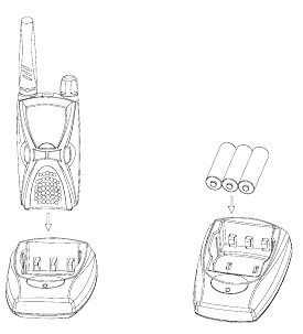
Charging Batteries
1. Charge the battery inside the radio
Insert the radio with battery vertically into the charging cup. Charging begins.
2. Charge the battery pack
Place the battery pack in the desktop charger. Make sure the “+” and “–“ markings of
the batteries match the ones in the charger. Charging begins.
Note: * Make sure the radio or the battery connects well with the charger before charging.
* The LED on the charger will glow red continuously while charging. LED glows
green when charging is complete.
* The desktop charger used to charge the AA rechargeable batteries should be
purchased separately. Or you can insert the radio with AA rechargeable batteries into the
charger to charge the batteries.
8
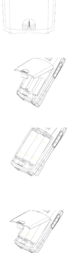
Installing Batteries
Push the battery latch upwards to loosen the battery
door. (See fig.1)
Fig.1
Lift battery door off. (See fig.2)
Fig. 2
Insert the battery into the radio. (See fig.3) Make
sure the “+” and “– “markings match the ones in the
compartment.
Fig.3
Attach battery door (see fig.4), pressing lightly
until latch clicks.
Fig.4
9
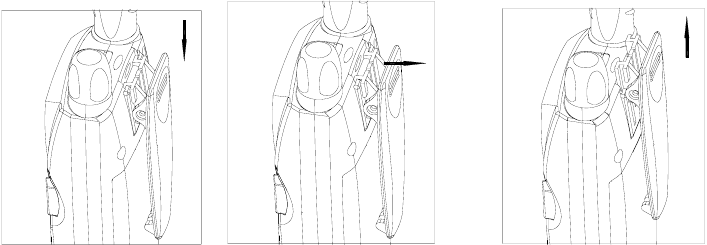
Accessory Installation
Belt Clip
Push the grooves of the belt clip along those at the top of the radio chassis until they
connect well. (See fig.5)
Press the tab between the battery cover and the belt clip along the indicated direction (See
fig.6). Slide the belt clip upwards along the radio chassis to detach the clip from the radio.
(See fig.7)
Fig.5 Fig.6 Fig.7
10
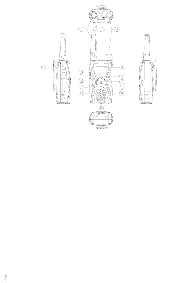
Getting Started
1. Antenna
2. Programming Jack
3. Speaker/Mic Jack
4. Power/Volume Knob
Rotate the Power/Volume Knob clockwise until a “click” is heard to turn the radio on,
fully counter clockwise to turn the radio off. When the radio is on, turn the knob to adjust
volume.
5. LCD Display
Indicate operation status of the radio. (Refer to “LCD Display” for details)
6. MENU key
In standby mode, briefly press MENU key to display current channel information and
hold down this key to enter menu mode. During setting, press MENU key to save and
switch to the next setting.
7. “-” key
Used to select the channel/interference eliminator code downwards or change menu
settings.
8. MON key
In standby mode, briefly press MON key to begin channel scanning; hold down MON
key to begin monitoring.
9. MIC
10. Speaker
11. “ ”key (CALL key)
If Call feature is enabled, briefly press the CALL key to transmit a call signal; During
setting, press CALL key to save and return to the first setting or exit; Hold down the CALL
key to lock/unlock keypad.
12. “+” key
Used to select the channel/interference eliminator code upwards or change menu
settings.
13. PTT button
Press and hold PTT, radio operates in transmit mode. Release PTT, radio returns to
receive mode.
14. Belt-Clip
Used to clip radio on your belt.
15. Charging Connectors
Connect the charging connectors with that on the charger to begin charging.
11
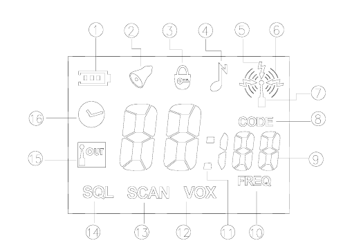
LCD Display
1. Battery Meter, used to indicate the battery power.
2. Appears when setting the Alarm Clock or the Alarm Clock is on; Flashes when the
Alarm Clock rings.
3. Appears when keypad lock is on.
4. Appears when setting the call tone.
5. Appears when receiving signals from the selected channel.
6. Appears when transmitting.
7. Appears when transmitting/receiving is enabled.
8. Indicate that the number on the LCD displays interference eliminator code and channel
number. The number under it indicates current interference eliminator code.
9. Two large “8”, a small “1” and two small “8” display the current channel number,
interference eliminator code, frequency number, time or the status of current setting.
10. Indicate that the number on the LCD displays channel number and frequency number.
The number above the icon indicates the frequency number of current channel.
11. Appears between hour and minute when LCD displays clock.
12. Appears when setting VOX or VOX feature is enabled.
13. Appears when scanning channel or setting channel scan add/delete.
14. Appears when setting squelch level.
15. Communication Range Alarm, flashes when your companion are out of range; appears
when setting communication range alarm or communication range alarm is enabled.
16. Appears when setting the clock.
12
Features and Operations
Basic Operation
Turning On/Off the Radio
Turn On: Rotate the Power/Volume Knob clockwise until a click is heard;
Turn Off: Rotate the Power/Volume Knob fully counter clockwise.
Operations under Radio Modes
Conventional Mode
Turn the power on to enter conventional mode.
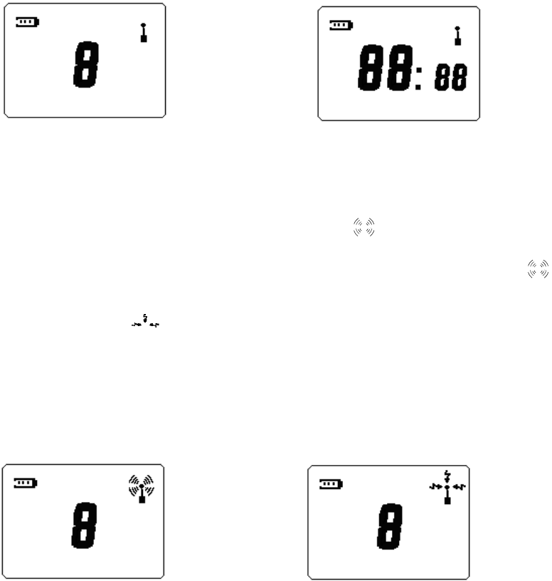
In conventional mode, if LCD displays channel number, the display is shown as figure 1-1;
if LCD displays clock, the display is shown as figure 1-2.
Figure1-1: LCD displays channel number Figure1-2: LCD displays clock
For example, if LCD displays channel number, you can operate as following:
1) Transmit and Receive
Press and hold PTT to enter transmitting mode, and “ ” appears on the LCD (See
figure2-1). Speak into the radio to talk. Release PTT to return to receive mode and “ ”
disappears.
The receiving icon “ ” appears when the selected channel receives a signal (See
figure2-2), the speaker is opened and you can hear the voice. If interference eliminator
code is set on the channel, you will only hear the voice of the user with the same
interference eliminator code as you.
You can talk without holding the radio by using PTT On external earphone.
Insert plug of earphone (with external PTT) into the accessory jack of the radio. Put on the
earphone and press PTT. Speak into the microphone to talk.
Figure2-1: Transmit Figure2-2: Receive
13
2) Call Tone
The call tone feature is valid only when you have set a call tone in the menu mode. You can
send a call tone to your partner before begin talking with him/her. Briefly press “ ” key to
transmit a call. The call tone will sound when you receive a call.
This feature can be enabled/disabled by the dealer.
3) VOX Feature
This feature is valid only when the radio is connected with external audio accessory.
Insert plug of VOX accessory into the accessory jack of the radio, set the VOX Sensitivity
Level in the menu mode, and then speak into the microphone to talk. When transmitting
using VOX feature, you will hear yourself talking through the accessory speaker. VOX
feature allows you to talk hands-free.
Press PTT key on the radio to disable VOX feature. This feature is enabled when you turn
on the power next time.
This feature can be enabled/disabled by the dealer.
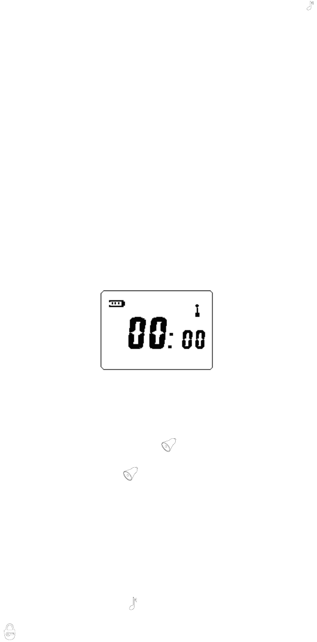
4) Clock Display
The clock display feature is valid only when you have selected clock display in the clock
and alarm clock setting mode.
When you turn on the power for the first time, the initial value of the clock is “00:00” (See
figure 3-1). The clock will work after you set the hour and minute. The icon “:” between the
hour and minute continues to display when the clock stops. When the clock begins to run,
the icon “:” flashes.
This feature can be enabled/disabled by the dealer.
Figure3-1: Clock Display “00:00”
5) Alarm Clock
The alarm clock is valid only when you have enabled alarm clock in the clock and alarm
clock setting mode.
In conventional mode, the alarm rings and “ ” icon flashes at the set time. Stop the
ringing by pressing any button and “ ” icon stops flashing at the same time.
This feature can be enabled/disabled by the dealer.
6) Channel Select
In conventional mode, pressing “+” / “-” key can select your wanted channel. The maximum
number you can select is decided by the number of available channels and the minimum
number is 1. Holding down “+” / “-” key can increase/decrease the channel number
continuously.
7) Keypad Lock
In conventional mode, holding down “ ” key can lock/unlock keypad. When keypad lock
is on, “ ” icon appears on the display and “+” / “-” and MON key are invalid. Holding
14
down MENU key and briefly pressing “ ” key are both invalid. The user can
transmit/receive through PTT key, briefly press MENU key to display channel information,
or hold down “ ” key to unlock the keypad.
This feature can be enabled/disabled by the dealer.
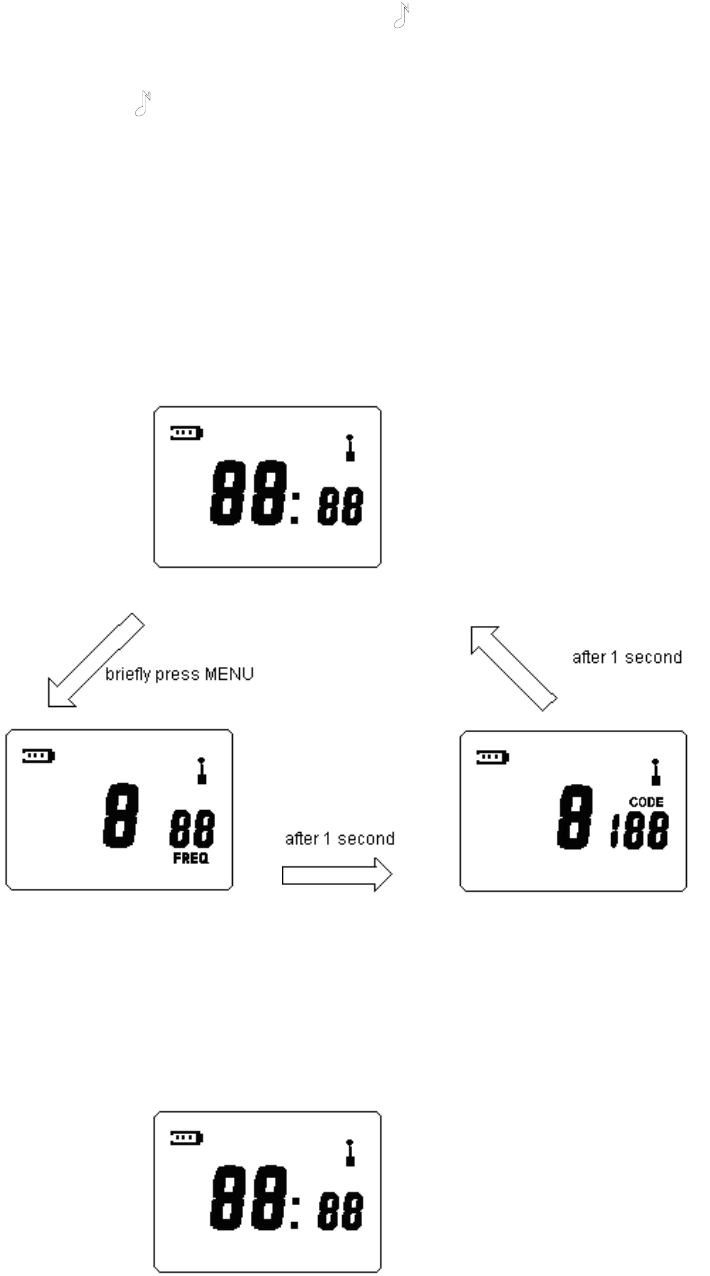
8) Channel Information Display
In clock display or channel number display mode, briefly press MENU key, LCD will display
channel number, frequency number and interference eliminator code of current channel.
For example, if LCD displays clock in standby mode (See figure4-1), and then:
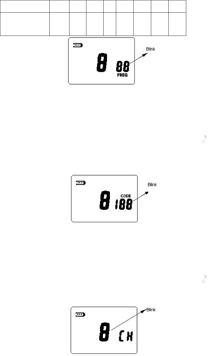
Briefly press MENU key, LCD will display frequency number of current channel at bottom
right corner. “FREQ” icon glows at the same time. LCD switches to interference eliminator
code display automatically after 1 second and “CODE” icon glows at the same time. LCD
returns to display clock after another 1 second.
Clock Display
Channel Number and Frequency Number Display Channel Number and Interference Eliminator Code Display
Figure4-1: Channel Information Display
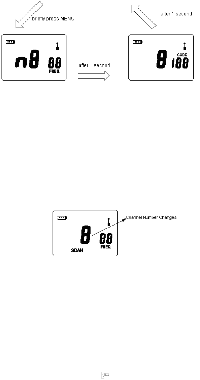
If the frequency indicated by the frequency number is changed through PC programming
software, LCD will display channel number and frequency number with an “n” in front of the
channel number indicating non-standard frequency number. (See figure5-1)
Clock Display
15
Channel Number and Non-standard Frequency Number Display Channel Number and Interference Eliminator Code Display
Figure5-1: Channel Information Display
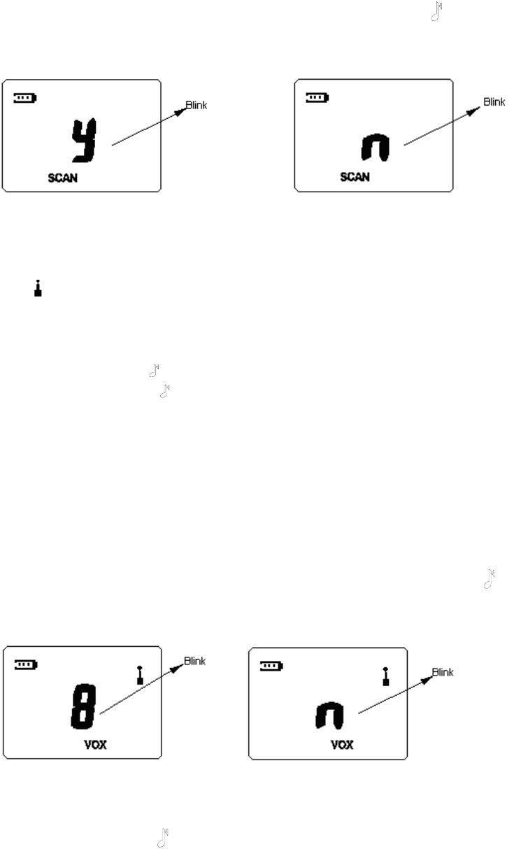
9) Channel Scan
Briefly press MON key in conventional mode to begin channel scanning. (See figure6-1)
LCD displays “SCAN” icon, channel number and frequency number of the channel. The
radio will stay on the active channel when detecting a valid signal and then continue to
scan upwards. You can press “+” / “-” to scroll through the active channel and resume
scanning upwards.
Press PTT during scanning to transmit on the selected channel before scanning and LCD
displays channel information; release PTT to receive on the same channel and then return
to scan mode.
If the set time is due during scan, the radio stops scanning and the alarm rings. Scan
resumes until the sound stops.
Briefly press MON key to stop scanning.
Figure6-1: Channel Scanning
10) Monitor
Press and hold MON key in conventional mode to begin monitoring.
This feature is used to receive weak signals, but will be interfered in by other noises and/or
unwanted signals.
Press MON key again to stop monitoring.
11) Low Battery Detect and Battery Power Indication
The radio will detect battery voltage periodically and indicate the battery power. The battery
power indicator on the top left corner of LCD will flash when the battery power is low. You
should recharge the battery or replace it with a fresh one.
12) Communication Range Alarm
The feature is valid only when you have enabled communication range alarm feature in the
menu mode.
The communication range alarm icon “ ” flashes and the radio beeps when you are
almost out of range during receiving. The beeps and flashing icon continue until you are
16
within the range again or turn the communication range alarm off.
This feature can be enabled/disabled by the dealer.
13) Battery Save
In conventional mode, when no activity is on channel and no key is pressed for 10 seconds,
the battery save feature will be turned on automatically.
This feature can be enabled/disabled by the dealer.
Clock and Alarm Clock Setting Mode
Turn the power on while holding down CALL and PTT key simultaneously. The radio enters
clock and alarm clock setting mode after 2 seconds.
In this mode, press “+” / “-” key to change setting; press MENU key to save and switch to
the next setting; press “ ” key to save and return to the first setting, if the current setting
is the first setting, press “ ” key to save and exit.
The current setting will flash when entering this mode. You can make settings as following:
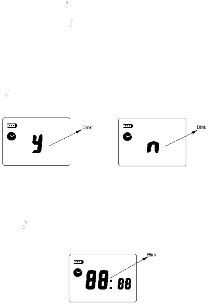
1) Set the display mode in standby mode (clock or channel number)
When setting the display mode in standby mode, clock icon appears on the left of the LCD
and the character “y” or “n” flashes (See figure7-1 and 7-2). “y” indicates that LCD displays
clock in standby mode and “n” indicates channel number. Press “+” / “-” key to select from
“y” and “n”. Press MENU key to confirm the setting and switch to the next setting. Press
“” key to save the setting and exit clock and alarm clock setting mode.
The factory default setting is to display channel number in standby mode.
Figure7-1: Clock Display Setting Figure7-2: Channel Number Display Setting
2) Set the hour of the clock
The hour of the clock will flash during setting (See figure8-1). Press “+” / “-” key to select
the hour from 0 to 23. Press MENU key to confirm the setting and switch to the next setting.
Press “ ” key to save the setting and return to the first setting or exit clock and alarm
clock setting mode.
The factory default setting for the hour is “00”.
Figure8-1: Setting the Hour
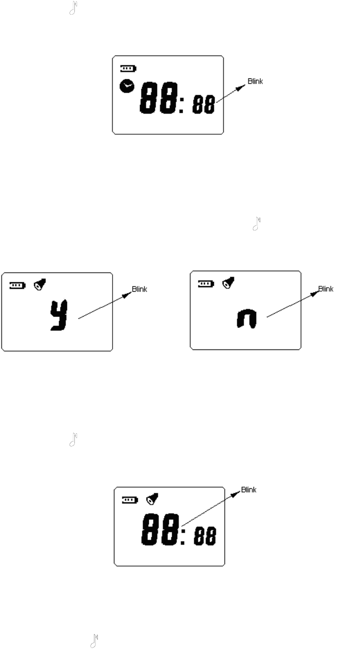
3) Set the minute of the clock
17
The minute of the clock will flash during setting (See figure9-1). Press “+” / “-” key to select
the minute from 0 to 59. Press MENU key to confirm the setting and switch to the next
setting. Press “ ” key to save the setting and return to the first setting or exit clock and
alarm clock setting mode.
The factory default setting for the minute is “00”.
Figure9-1: Setting the Minute
4) Turn on/off the alarm clock
When setting the alarm clock, alarm clock icon appears on the top left corner of LCD and
the character “y” or “n” flashes (See figure10-1 and 10-2). “y” indicates turning the alarm
clock on and “n” indicates off. Press “+” / “-” key to select from “y” and “n”. Press MENU key
to confirm the setting and switch to the next setting. Press “ ” key to save the setting and
return to the first setting or exit clock and alarm clock setting mode.
The factory default setting for the alarm clock is off.
Figure10-1: Turn on the Alarm Clock Figure10-2: Turn off the Alarm Clock
5) Set the hour of the alarm clock
The hour of the alarm clock will flash during setting (See figure11-1). Press “+” / “-” key to
select the hour from 0 to 23. Press MENU key to confirm the setting and switch to the next
setting. Press “ ” key to save the setting and return to the first setting or exit clock and
alarm clock setting mode.
The factory default setting for the hour of the alarm clock is “00”.
Figure11-1: Setting the Hour of Alarm Clock
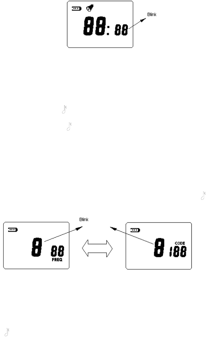
6) Set the minute of the alarm clock
The minute of the alarm clock will flash during setting (See figure12-1). Press “+” / “-” key to
select the minute from 0 to 59. Press MENU key to confirm the setting and switch to the
next setting. Press “ ” key to save the setting and return to the first setting or exit clock
18
and alarm clock setting mode.
The factory default setting for the minute of the alarm clock is “00”.
Figure12-1: Setting the Minute of Alarm Clock
Channel Setting Mode
Turn the power on while holding down MON and PTT key simultaneously. The radio enters
channel setting mode after 2 seconds.
In this mode, press “+” / “-” key to change setting; press MENU key to save and switch to
the next setting; press “ ” key to save and return to the first setting, if the current setting
is the first setting, press “ ” key to save and exit.
The current setting of channel setting will flash when entering this mode. You can make
settings as following:
1) Select channel number
During setting, the channel number flashes (See figure13-1). LCD displays frequency
number and interference eliminator code of the current channel alternately. Press “+” / “-”
key to select channel number. The maximum number you can select is decided by the
number of available channels and the minimum number is 1.
Press MENU key to confirm the setting and switch to the next setting. Press “ ” key to
save the setting and exit channel setting mode.
a. Display Channel Number and Frequency Number b. Display Channel Number and Interference Eliminator Code
Figure13-1: Select Channel Number
2) Set frequency number
When setting frequency number of the channel, “FREQ” icon appears on LCD and the
frequency number flashes (See figure14-1). Press “+” / “-” key to select frequency number
from 1 to 56. Press MENU key to confirm the setting and switch to the next setting. Press
“” key to save the setting and return to the first setting or exit channel setting mode.
This feature can be enabled/disabled by the dealer.
19
The factory default setting for frequency number of each channel is shown as following:
Channel No. 1 2 3 4 5 6 7 8
Frequency Number
7
15
16
31
34
45
48
52
Figure14-1: Set Frequency Number
3) Set interference eliminator code
When setting interference eliminator code of the channel, “CODE ”icon appears on LCD
and the interference eliminator code flashes (See figure15-1). Press “+” / “-” key to select
interference eliminator code from 0 to 121. If “0” is selected, interference eliminator code is
not set in a channel.
Press MENU key to confirm the setting and switch to the next setting. Press “ ” key to
save the setting and return to the first setting or exit the channel setting mode.
This feature can be enabled/disabled by the dealer.
In factory default setting, interference eliminator code is not set in all channels.
Figure15-1: Set Interference Eliminator Code
4) Set the number of available channels
When setting the number of available channels, “CH ”icon appears on LCD and the
channel number flashes (See figure16-1). Press “+” / “-” key to select number of available
channels from 1 to 8.
Press MENU key to confirm the setting and switch to the next setting. Press “ ” key to
save the setting and return to the first setting or exit the channel setting mode.
In factory default setting, the number of available channels is 8.
Figure16-1: Set the Number of Available Channels
5) Channel Scan Add/Delete
When setting channel scan add/delete, “SCAN” icon appears on the bottom of LCD and
the character “y” or “n” flashes (See figure17-1 and 17-2). “y” indicates channel scan add
and “n” indicates channel scan delete. Press “+” / “-” key to select from “y” and “n”. Press
20
MENU key to confirm the setting and switch to the next setting. Press “ ” key to save the
setting and return to the first setting or exit the channel setting mode.
In factory default setting, all the channels are added to scan list.
Figure17-1: Channel Scan Add Figure17-2: Channel Scan Delete
Menu Mode
In conventional mode, hold down MENU key to enter menu mode. LCD displays antenna
icon “ ” indicating that transmission/receiving is available. When pressing PTT to transmit,
LCD displays channel information; when releasing PTT, LCD returns to the display before
transmitting.
In this mode, press “+” / “-” key to change setting; press MENU key to save and switch to
the next setting; press “ ” key to save and return to the first setting, if the current setting
is the first setting, press “ ” key to save and exit.
The current setting of menu mode will flash when entering this mode. You can make
settings as following:
1) Set VOX Feature
When setting VOX feature, “VOX” icon appears on LCD and the VOX sensitivity level or
character “n” flashes (See figure18-1).
There are five sensitivity levels (level 1 to level 5). The higher the sensitivity level, the lower
audio needed to trigger a transmission. The VOX feature is disabled when “n” is selected.
Press “+” / “-” key to select sensitivity level or disable VOX feature.
Press MENU key to confirm the setting and switch to the next setting. Press “ ” key to
save the setting and return to the first setting or exit the menu mode.
In factory default setting, the VOX feature is disabled.
a. Select VOX Sensitivity Level b. Disable VOX Feature
Figure18-1: Set VOX Feature
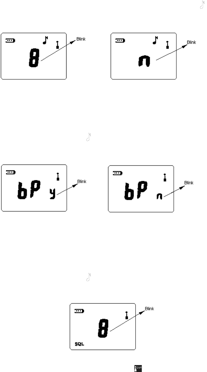
2) Set Call Tone
When setting call tone, “ ” icon appears on LCD and the call tone number or character
“n” flashes (See figure19-1).
There are five distinct call tones (1-5). The call tone feature is disabled when “n” is
selected.
Press “+” / “-” key to choose from call tones 1-5 or disable call tone. The radio plays a
sample of each call tone as you select them.
21
Press MENU key to confirm the setting and switch to the next setting. Press “ ” key to
save the setting and return to the first setting or exit the menu mode.
In factory default setting, the call tone 1 is selected.
a. Select Call Tone b. Disable Call Tone
Figure19-1: Set Call Tone
3) Set Button Beep
When setting button beep, “bP” icon appears on LCD and the character “y” or “n” flashes
(See figure20-1). “y” indicates enabling button beep and “n” indicates disabling.
Press “+” / “-” key to select from “y” and “n”. Press MENU key to confirm the setting and
switch to the next setting. Press “ ” key to save the setting and return to the first setting
or exit menu mode.
In factory default setting, the button beep is enabled.
a. Enable Button Beep b. Disable Button Beep
Figure20-1: Set Button Beep
4) Select Squelch Level
When setting squelch level, “SQL” icon appears on bottom left corner of the LCD and the
squelch level flashes (See figure21-1).
There are four squelch levels (1-4). Higher squelch level makes it harder for the radio to
receive weak signals and avoid interference of noises and/or unwanted signals.
Press “+” / “-” key to select squelch level. Press MENU key to confirm the setting and
switch to the next setting. Press “ ” key to save the setting and return to the first setting
or exit the menu mode.
In factory default setting, squelch level is set as 2.
Figure21-1: Select Squelch Level
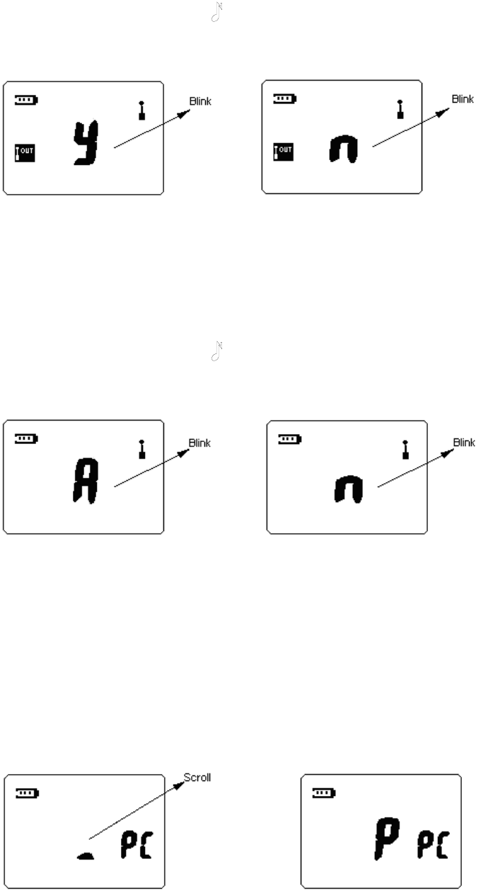
5) Set Communication Range Alarm
When setting communication range alarm feature, “ ” icon appears on the left of LCD
and the character “y” or “n” flashes (See figure22-1). “y” indicates enabling communication
range alarm and “n” indicates disabling.
22
Press “+” / “-” key to select from “y” and “n”. Press MENU key to confirm the setting and
switch to the next setting. Press “ ” key to save the setting and return to the first setting
or exit menu mode.
In factory default setting, the communication range alarm is disabled.
a. Enable Communication Range Alarm b. Disable Communication Range Alarm
Figure22-1: Set Communication Range Alarm
6) Set Battery Type
Setting the battery type allows the radio to detect low battery and properly display the
power usage. When setting the battery type, the character “A” or “n” flashes (See
figure23-1). “A” indicates rechargeable battery and “n” indicates non-rechargeable one.
Press “+” / “-” key to select from “A” and “n”. Press MENU key to confirm the setting and
switch to the next setting. Press “ ” key to save the setting and return to the first setting
or exit menu mode.
In factory default setting, the battery type is rechargeable battery.
a. Rechargeable Battery b. Non-rechargeable Battery
Figure23-1: Set Battery Type
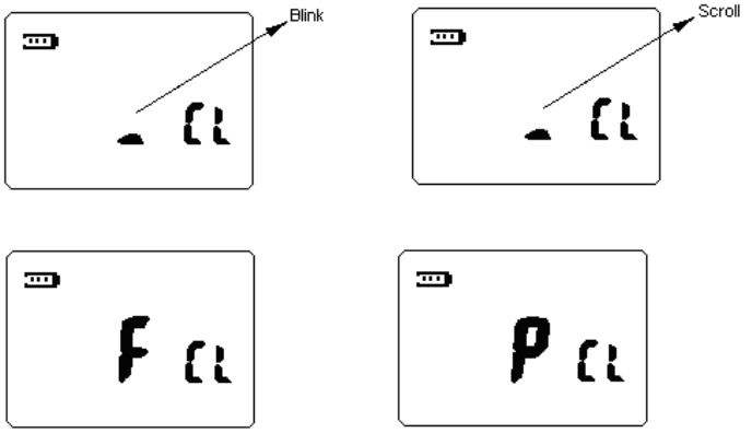
PC Programming Mode
In standby mode, connect the radio and a PC with programming cable and then
programme the radio through programming software, the radio enters PC programming
mode. LCD display is shown as figure24-1. During programming, the black cursor in the
center of LCD will scroll. When programming is complete, the character “P” will be
displayed on the center of LCD. In the PC programming mode, the radio communicate with
PC through UART port, all the commands are carried out via PC. After programming, the
radio should be turned off and back on again to use.
a. Programming b. Programming Over
Figure24-1: PC Programming Mode
23
Wired Clone Mode
Connect the radio with cloning cable and then turn the power on while holding down CALL
and MON key simultaneously. After 2 seconds, the radio enters wired clone mode (source
side).
When the radio enters wired clone mode, LCD display is shown as figure25-1. The black
cursor in the center of LCD flashes. When the target radio is ready, press MON key to
begin cloning. The black cursor in the center of LCD will scroll. During cloning, if an error
occurs or the target radio has no response, the cloning stops and LCD displays error
prompt. “F” (FAIL) indicates that wired clone is failed. If data is cloned successfully, “P”
(PASS) appears.
a. Wired Clone Ready b. Cloning
c. Clone Failure d. Clone Successfully
Figure25-1: Wired Clone Mode
Default Setting Mode
This feature is used to enter conventional mode and restore all the radio settings to factory
default setting.
Turn the power on while holding down “+” and “-” key simultaneously, all the radio data are
initialized after 2 seconds. And then the radio returns to conventional mode.
This feature can be enabled/disabled by the dealer.

24
Appendix 1: Channel Frequency (461.0375 MHz - 469.5625 MHz)
Frequency Number Frequency (MHz) Frequency Number Frequency (MHz)
1 464.5000 29 462.9125
2 464.5500 30 464.4875
3 467.7625 31 464.5125
4 467.8125 32 464.5375
5 467.8500 33 464.5625
6 467.8750 34 466.0375
7 467.9000 35 466.0625
8 467.9250 36 466.0875
9 461.0375 37 466.1125
10 461.0625 38 466.1375
11 461.0875
39 466.1625
12 461.1125 40 466.1875
13 461.1375 41 466.2125
14 461.1625 42 466.2375
15 461.1875 43 466.2625
16 461.2125 44 466.2875
17 461.2375 45 466.3125
18 461.2625
46 466.3375
19 461.2875 47 466.3625
20 461.3125 48 467.7875
21 461.3375 49 467.8375
22 461.3625 50 467.8625
23 462.7625 51 467.8875
24 462.7875 52 467.9125
25 462.8125
53 469.4875
26 462.8375 54 469.5125
27 462.8625
55 469.5375
28 462.8875
56 469.5625

25
Appendix 2: CTCSS Table (38)
No. FrequencyHz No. FrequencyHz
1 67.0 20 131.8
2 71.9 21 136.5
3 74.4 22 141.3
4 77.0 23 146.2
5 79.7 24 151.4
6 82.5 25 156.7
7 85.4 26 162.2
8 88.5 27 167.9
9 91.5 28 173.8
10 94.8 29 179.9
11 97.4 30 186.2
12 100.0 31 192.8
13 103.5
32 203.5
14 107.2 33 210.7
15 110.9 34 218.1
16 114.8 35 225.7
17 118.8 36 233.6
18 123.0 37 241.8
19 127.3
38 250.3

26
Appendix 3: CDCSS Table (83)
No. CDCSS No. CDCSS
39 023 82 331
40 025 83 343
41 026 84 346
42 031 85 351
43 032 86 364
44 043 87 365
45 047 88 371
46 051 89 411
47 054 90 412
48 065 91 413
49 071 92 423
50 072 93 431
51 073
94 432
52 074 95 445
53 114 96 464
54 115 97 465
55 116 98 466
56 125 99 503
57 131
100 506
58 132 101 516
59 134 102 532
60 143
103 546
61 152 104 565
62 155 105 606
63 156 106 612
64 162 107 624
65 165 108 627
66 172
109 631
67 174 110 632
68 205 111 654
69 223
112 662
70 226 113 664
71 243 114 703
72 244 115 712
73 245 116 723
74 251 117 731
75 261
118 732
76 263 119 734
77 265 120 743
78 271 121 754
79 306
80 311
81 315

27
Troubleshooting Guide
Care and Cleaning
Do not carry your radio by the antenna or remote microphone;
Wipe the battery contacts with a lint-free cloth to remove dirt, grease, or other material
that may prevent good electrical connection;
When not in use, keep the accessory jacks covered with the protective caps;
Clean the shell, controls and keys of your radio with neutral detergent and warm water
after a long period of usage. Avoid using strong chemicals.
Optional Accessories
AC Adaptor: PDS-259 (Part No.: 420855203331)
Charger: HC1688AWC (Part No.: 420855203348)
Strap (Part No.: 420855203362)
Ear Loop: 258V-G-P (Part No.: 420855203065)
Ear Bud: 258V-S-P (Part No.: 420855203041)
Belt Clip (Part No.: 420855203393)
AWC endeavor to achieve the accuracy and completeness of this manual, but cannot
guarantee its accuracy at all times. All the above specifications and design are subject to
change by AWC without notice.
All the reproduction and translation of this manual without authorization of AWC is not
allowed.
Trouble Solution
No power
Battery may be used up. Please replace or
recharge the battery.
Battery may not be attached properly. Remove
the battery and attach again.
Power doesn’t last long even if fully
charged.
Battery life cycle is over. Please replace it with a
new one.
Can’t talk to or hear other users in
your group.
Make sure you are using the same frequency
and CTCSS/CDCSS tone as other users in your
group.
Other users may be too far away. Make sure you
are within the communication range.
Voice of other users (non-group
user) appears on the channel.
Please change your CTCSS/CDCSS tone. Be
sure to change the tone on all the other radios in
your group.