Norton 7200 Electromechanical Closer 43063
User Manual: Norton 7200 Electromechanical Closer Catalog
Open the PDF directly: View PDF ![]() .
.
Page Count: 16
7200 series
Electromechanical
Closer/Holder
7200 SERIES
ElEctRomEchanIcal cloSER/holdER
2
INTRODUCTION
Copyright © 2005-2016, Yale Security Inc., an ASSA ABLOY Group company. All rights reserved.
Reproduction in whole or in part without the express written permission of Yale Security Inc. is prohibited.
TABLE OF CONTENTS
The 7200 Series Electromechanical Closer/Holders combine the functions
of an electromechanical door holder with the 7700 series door closer. The
7200 features a choice of two types of hold open functions:
Selective Hold Open (Standard): The door will hold open at any degree of
opening beyond a pre-set hold open point, up to 175°, with a maximum
allowable door opening of 180° (the exception is series 7250 which opens
to 110°).
Infinite Hold Open: The door will hold open at any degree of opening up
to 175° with a maximum allowable door opening of 180° (the exception
is series 7250 which opens to 110°). Infinite Hold Open can be set in the
field by turning the cam.
Overview, Basic Units, Specifications ................................................................. 3
Features..................................................................................... 4
Compliance Standards, How To Order ................................................................ 5
7210/7250
Master Units ............................................................................6-7
Slave/Support Units........................................................................ 8
7220/7230
Master Units ...........................................................................9-10
Slave/Support Units....................................................................... 11
7240 Connected Free Swing Releasing Device ......................................................... 12
7290 Overhead Concealed Units .................................................................. 13
Parts ....................................................................................14-15
3
OVERVIEW
Copyright © 2005-2016, Yale Security Inc., an ASSA ABLOY Group company. All rights reserved.
Reproduction in whole or in part without the express written permission of Yale Security Inc. is prohibited.
7200 SERIES
ElEctRomEchanIcal cloSER/holdER
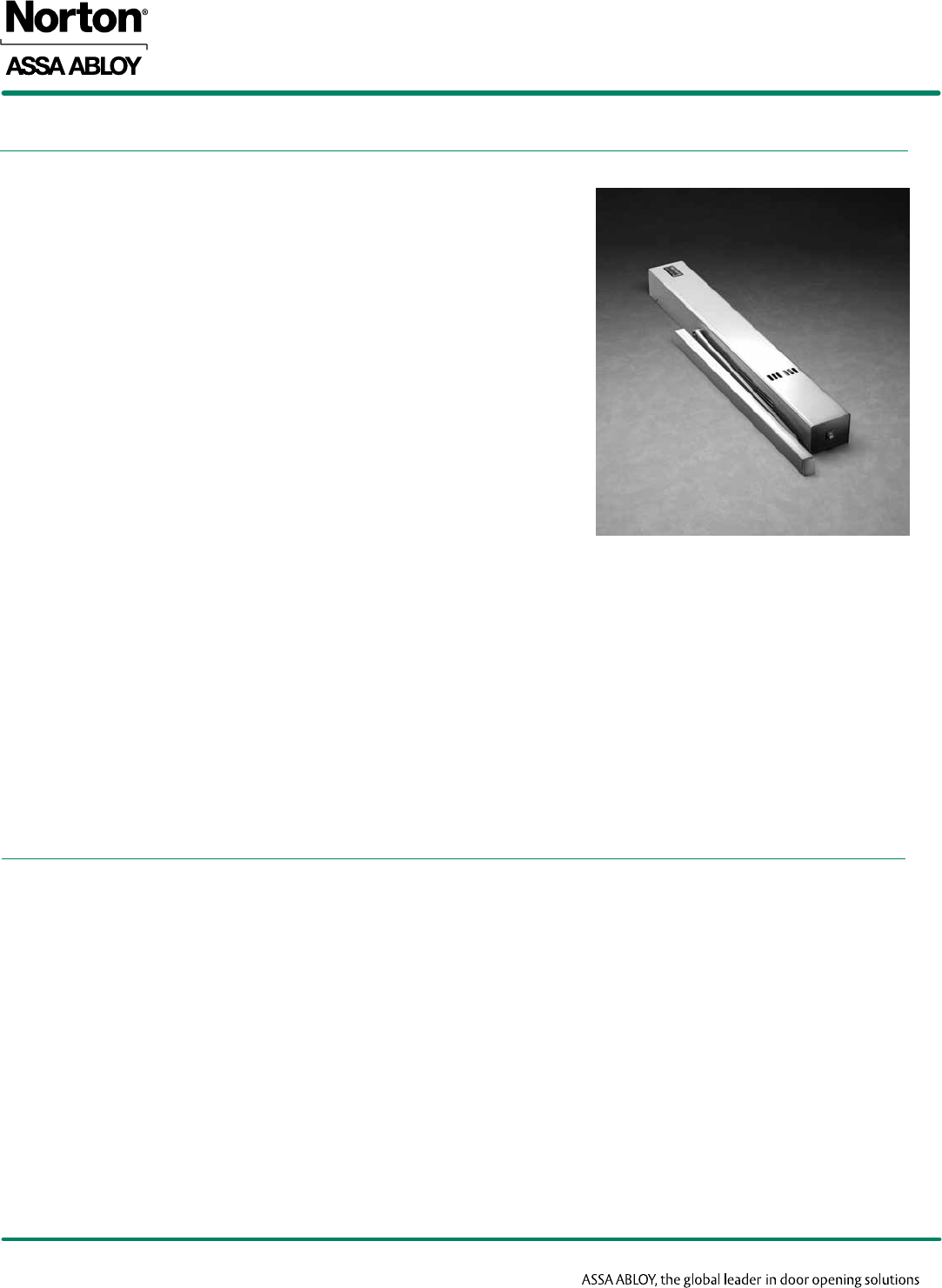
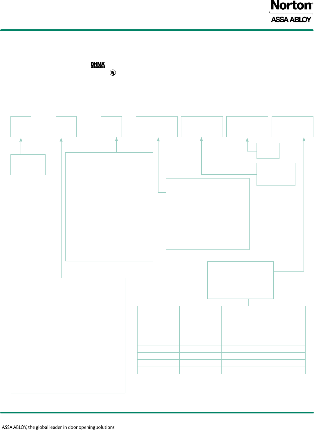
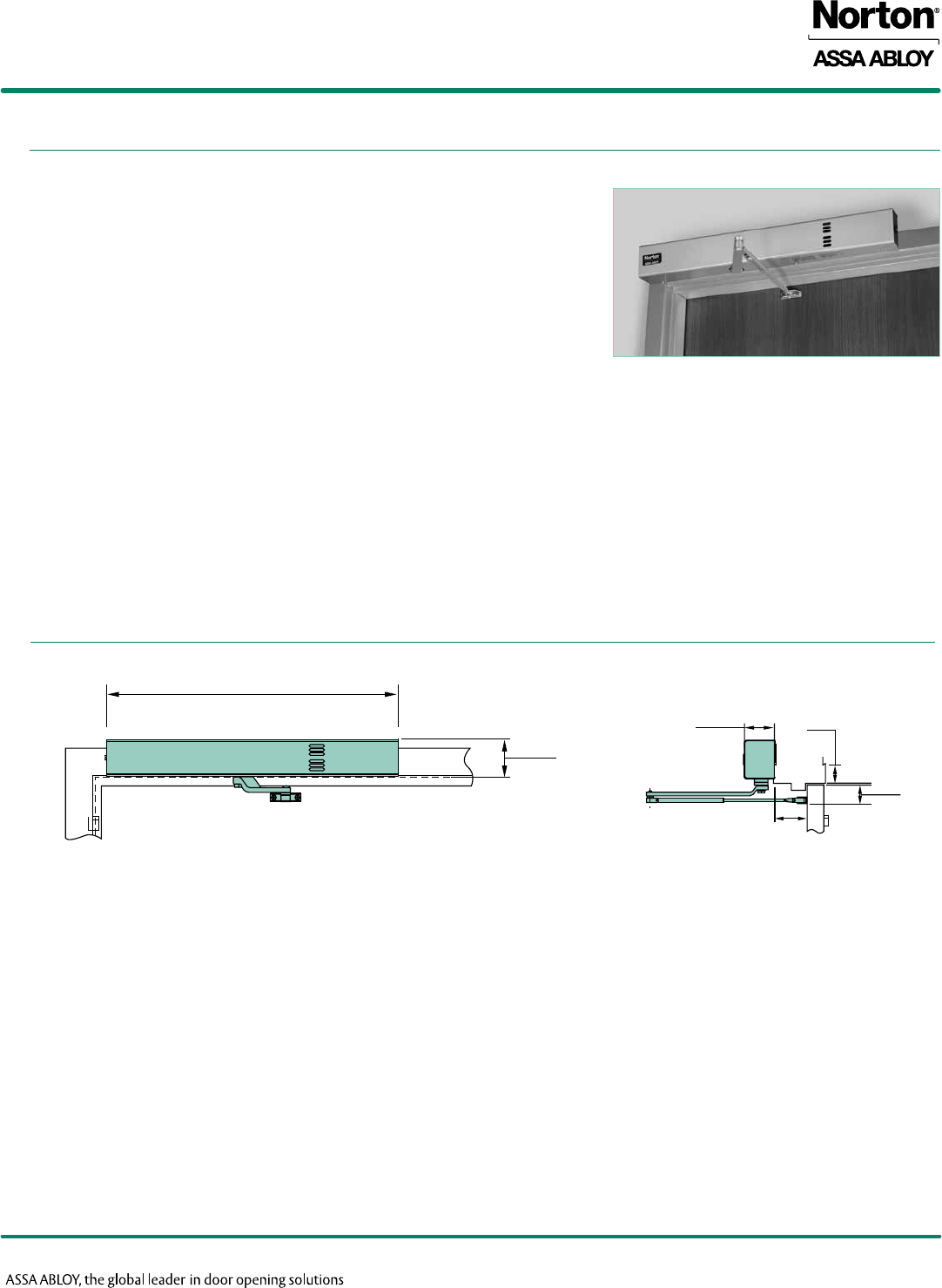
Master Unit: 7200MPDO
Consists of an on-board power supply (for 120VAC input option) or a
terminal strip (for 24VDC input option), an integral smoke detector module
and a door closer assembly with internal electro-hydraulic holder capability.
A Master Unit can control a single door or one leaf of a pair of doors. A
24VDC Slave/Support Unit is required on the opposite door leaf.
Slave/Support Units: 7200MPSO
Identical in size to the Master Unit, the Slave/Support Unit consists of an
on-board power supply (for 120VAC input option) or a terminal strip (for
24VDC input option) and a door closer assembly with internal electro-
hydraulic holder capability. This unit (120VAC or 24VDC) is intended to
control a single door or a pair of doors where the building's alarm system
monitors the power to the Slave/Support Unit (24VDC input) or to control
the inactive leaf of a pair of doors where the active leaf is controlled by a
Master Unit.
Executive™ Unit: RFS Suffix
Identical in size and appearance to a Master Unit, the Executive Unit
consists of an on-board power supply (for 120VAC input option) or a
terminal strip (for 24VDC input option), a 433MHz radio frequency
receiver and a door closer assembly with internal electro-hydraulic holder
capability. Unit is intended to provide remote wireless release of a door
that has been manually placed into the electrified hold open position. Not
intended for use in life safety applications.
Closer for __________ doors shall be electromechanical (with integral smoke detector) and completely enclosed in a metal cover. Units shall be surface
mounted to the frame face [on the pull (hinge side) or the push (opposite hinge side)] of the door [and shall project no more than 2-11/16" (68mm) from
the surface of the frame]. (Closer shall be installed in the header of the frame, and the slide track mortised into the door’s top rail). Closer unit shall be
hydraulic, full rack and pinion type with a cast aluminum alloy shell. Hydraulic fluid shall be non-gumming and non-freezing. Closer unit shall have two non-
critical valves to independently regulate closing and latch speed. It shall also have an adjustable backcheck with a hex-key. Closer unit shall have spring
power adjustment to permit a 50% increase in closing power over the minimum closing force for any size. Electromechanical Closer shall have (Infinite)
(Selective) Hold Open (Free Swing Operation) and shall be able to attain a maximum opening of 180° (with hold open to 175°). Unit to be fail safe and
must close the door during any electrical power interruption to the unit. (Closer/Holder to be Executive Door Holder/Release with release actuated by
battery operated hand-held controller). Unit(s) to operate on (120VAC, 60Hz) (24VDC) and will accept (surface) (concealed) wiring. Amperage draw shall
not exceed (.105 Amps for 24VDC) (0.46 Amps for 115VAC) units. Supplier to coordinate electrical requirements with electrical and alarm system engineers.
Wiring (and conduit) by others.
Electromechanical Units to be Norton® Series 7200 (Closer/Holder) (Free Swing Releasing Device), (Executive Door Holder/Release).
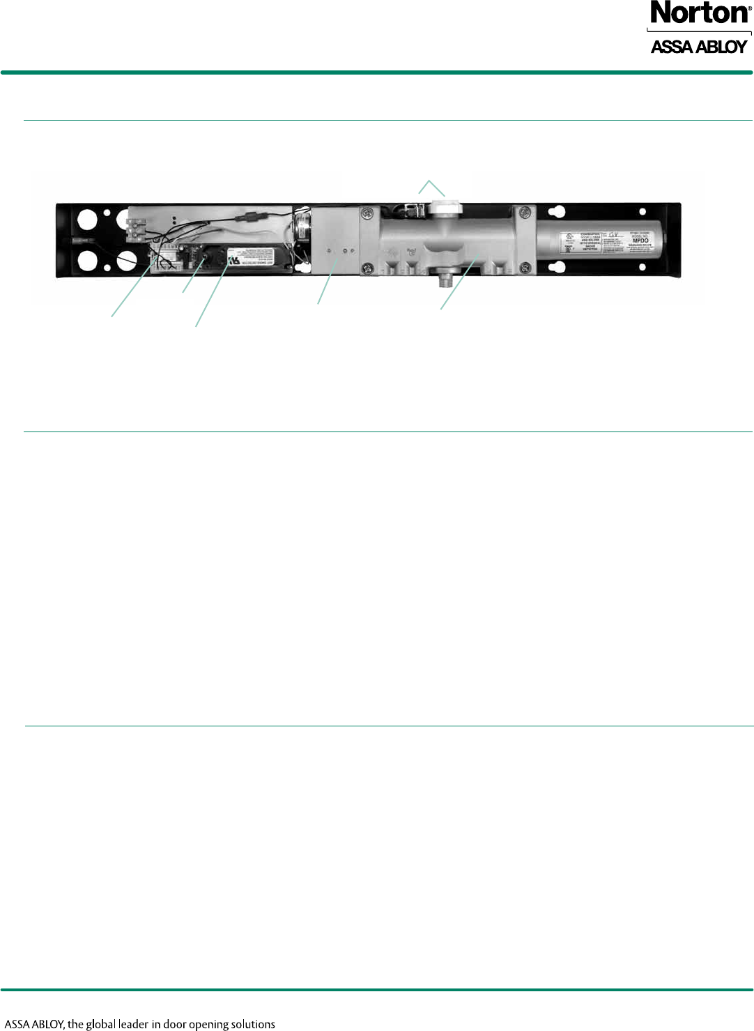
Closer Body
Electrohydraulic
Holder
Selective Hold Open Cam
& Switch
Test Switch*
Input & Control
Terminal Strip Smoke Detector
Module*
BASIC UNITS
SPECIFICATIONS
Master Unit Shown
*Master Unit Only
7200 SERIES
ElEctRomEchanIcal cloSER/holdER
4
FEATURES
Copyright © 2005-2016, Yale Security Inc., an ASSA ABLOY Group company. All rights reserved.
Reproduction in whole or in part without the express written permission of Yale Security Inc. is prohibited.
UNITS WITH DETECTORS
Fire/Smoke Control Circuit:
Interprets the signal from the detector and provides switching contacts to
interrupt hold open solenoid, to sound alarms, etc.
Alarm (Relay) Contacts:
Normally open in standby condition (operating and sensing for smoke
condition). These contacts close during an alarm condition (smoke detected)
and may be used to switch power from the solenoid to an optional local
alarm.
Trouble (Relay) Contacts:
Normally closed in standby condition, these supervisory contacts monitor
the continuity of power within the detector circuit. Any power interruption
within the detector circuit will open these contacts. They can then be used
to simultaneously indicate a Trouble Condition to the Alarm Panel on a
separate trouble circuit.
Locked-In Alarm:
The unit which alarms must be manually reset. This can be accomplished
by remote control from the alarm system panel or by the reset switch in
the smoke detector module. Reset switch is accessible through the center
louver in the cover. Reset by rotating LED chambers using small flat blade
screwdriver.
Indicator Lights:
Normal Mode: A red LED flashes once every eight (8) seconds.
Clean Mode: A red LED flashes once every second.
Alarm Mode: A red LED illuminates continuously.
Test Switch:
Permits door to be released from hold open without causing a “trouble
condition” at the alarm panel. Allows for periodic testing of the automatic
door release function.
Aluminum Alloy Housing
Closer bodies are constructed of a special aluminum alloy, carefully
selected to accommodate interactive steel components and operating
conditions.
Rack & Pinion Operation
Provides a smooth constant control of the door through its full opening and
closing cycle.
Spring Sizes
Specify closer size 3, 4 or 5. Size 6 available with 7290 overhead
concealed units.
Sweep Speed Control Valve
Allows adjustment of door speed from the door’s full open position down to
approximately 10° from the closed position.
Latch Speed Control Valve
Allows adjustment of door speed from approximately 10° down to the
door’s fully closed position.
Adjustable Backcheck Cushioning
Provides control of the door in the opening cycle, beginning at
approximately 75° of door opening. It slows/cushions the door opening,
when the door is forcibly opened beyond its pre-adjusted limits.
Adjustable Backcheck Position Valve
Allows the door opening position, where backcheck cushioning begins, to
be adjusted to a greater door angle, up to a maximum of 20° farther
(approximately 95°).
Handed
Specify right or left hand when ordering.
Selective Hold Open (Standard)
The door will hold open at any degree of opening beyond a pre-set hold
open point, up to 175°, with a maximum allowable door opening of 180°
(exception series 7250 at 110°).
Infinite Hold Open
The door will hold open at any degree of opening up to 175°, with a
maximum allowable door opening of 180° (exception series 7250 at 110°).
Can be set in the field by turning cam.
Fail Safe
In the event of a power failure, the solenoid will de-energize and the
closer/holder will then operate as a normal door closer.
Wiring Option
All 7200 Series Electromechanical Closer/Holders will accommodate
either concealed or surface wiring.
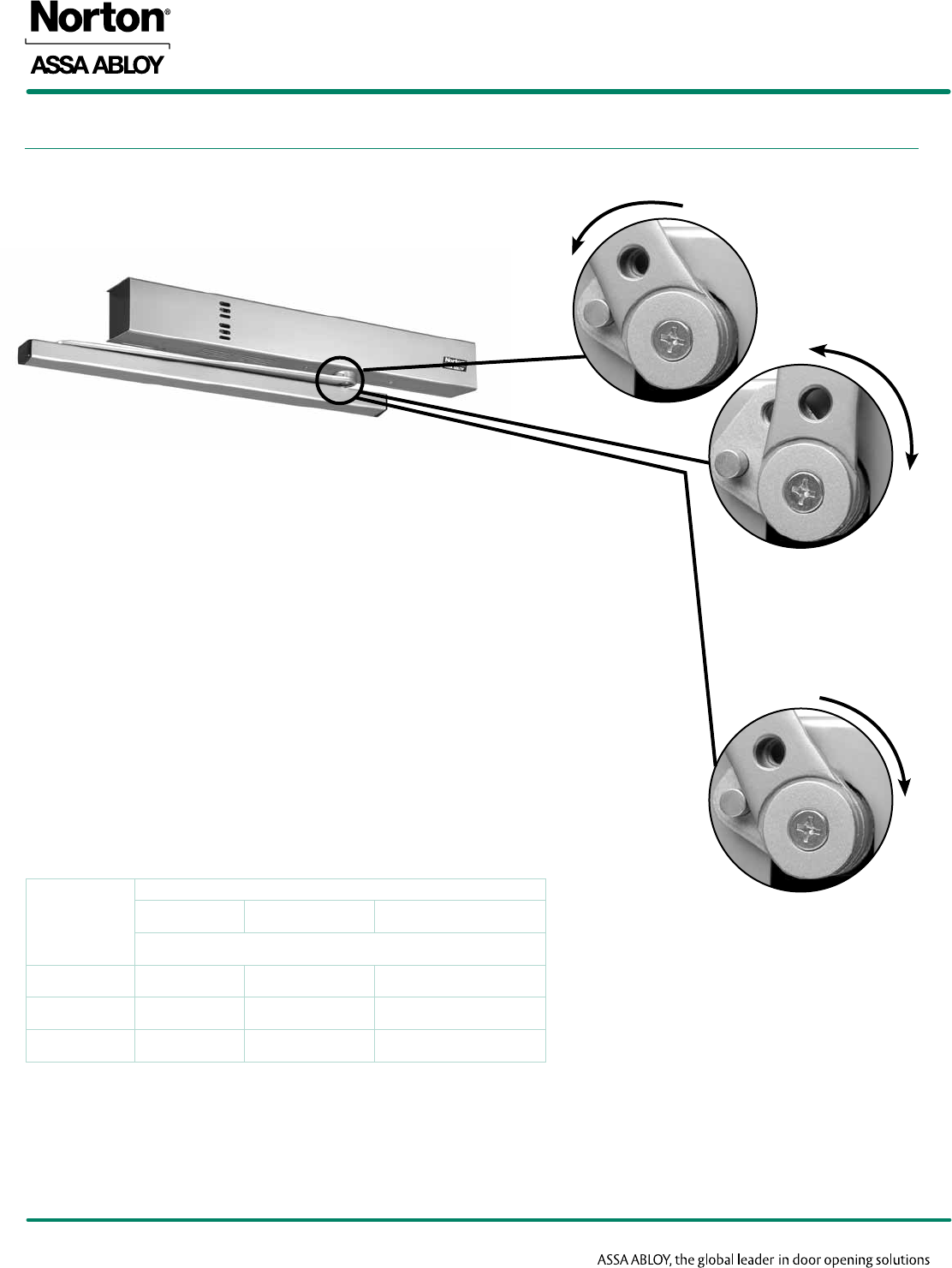
Selective Hold Open Switch and Cam:
The Selective Hold Open starting point is determined by a switch and
adjustment cam assembly. The cam is attached to the upper pinion shaft
by means of a machine screw. As the door is opened, the pinion shaft will
rotate the cam and operate the switch to the “on” position to initiate hold
open. When the door is closed, the pinion cam will operate the switch to
the “off” position. The cam is factory set to operate at 80° of door opening.
The cam can be easily field adjusted to operate at virtually any degree of
door opening.
5
COMPLIANCE STANDARDS
Copyright © 2005-2016, Yale Security Inc., an ASSA ABLOY Group company. All rights reserved.
Reproduction in whole or in part without the express written permission of Yale Security Inc. is prohibited.
7200 SERIES
ElEctRomEchanIcal cloSER/holdER
HOW TO ORDER
• ANSI/BHMAA156.15certified
• UL/cULlistedforuseonfirerateddoors
• UL10Clistedforpositivepressurefiretest
• ThisproductismanufacturedinanISO9001facility
*600 is a special rust-inhibiting prime coat. Closers can be ordered prime coat only
(specify closer x 600). An additional charge applies if finish coat is required over
prime coat (ex: 7214MPDO x 600 x 689).
72 1 4 MPDO x Voltage x Finish
7200 Series
Closer/Holder
Specifies side of door unit is mounted
on and the type of arm
Pull Side
“1” - Rigid Slide Arm & Track
Maximum reveal 1/8" (3mm)
“4” - Connected Free Swing Slide Arm & Track
Maximum reveal 1/8" (3mm)
“5” - Double Egress Slide Arm & Track
Reveals 1/8"-3" (3-76mm) to 110°
“9” - Overhead Concealed Door Closer with
Rigid Slide Arm & Track
Push Side
“2” - Double Lever Arm
Reveals 2-3/4"-4" (70-120mm) to 180°
Reveals 4"-7" (102-179mm) to 165°
“3” - Double Lever Arm
Reveals 4"-7" (102-179mm) to 180°
Closer Size
Slide Arm & Track Maximum
and Connected Door Size
Free Swing Arm
“3” 40"
“4” 44"
“5” 48"
Overhead Concealed
“4” 32"
“5” 38
“6” 48"
Double Lever Arm
“3” 42"
“4” 48"
x Hand
FINISHES
Product will be sprayed with
a combination of waterborne
acrylic and polyester powder
coat.
Suffix:
Selective Hold Open
MPDO - Master Unit
MPSO - Slave/Support (24VDC only
when used with Master Unit)
Executive™ Door Release
RFS - Selective Hold Open
D - Drop Application
(7220, 7230 only)
RH - Right Hand
LH - Left Hand
120VAC
24VDC
Description Specify Designation
(BHMA)
Complements the
following finishes
Old Designa-
tion
Aluminum 689 628, 625, 629, 630, 651,
652 AL
Statuary Bronze 690 640, 613 STAT
Dull Bronze 691 612, 637, 639 DB
Black 693 315 315
Medium Amber 694 312 312
Gold 696 605, 606, 632, 633 GB
Prime Coat* 600 SRI
7200 SERIES
ElEctRomEchanIcal cloSER/holdER
6
MASTER UNITS
Copyright © 2005-2016, Yale Security Inc., an ASSA ABLOY Group company. All rights reserved.
Reproduction in whole or in part without the express written permission of Yale Security Inc. is prohibited.
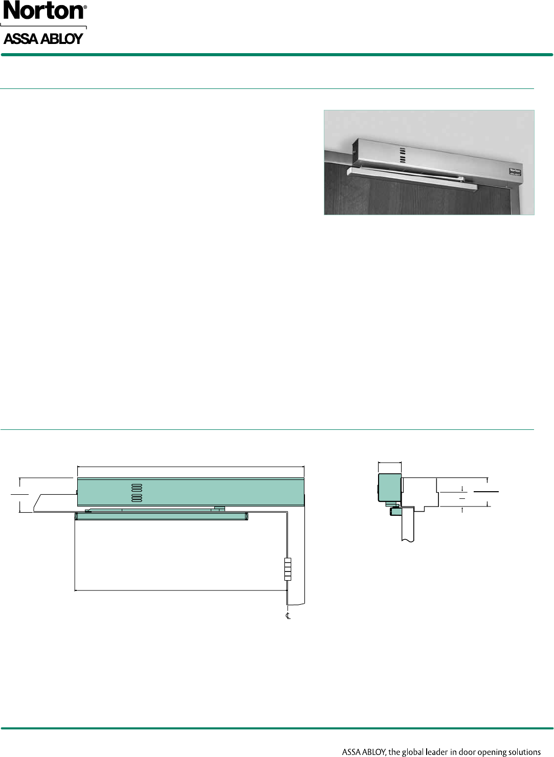
• Surface mounted to the pull (hinge) side frame face
• Slide track mounts directly to door
• Minimum 4" ceiling clearance required
• 1/8" (3mm) – standard frame reveal. For deeper reveals, a special slide
arm is required (see chart on page 7).
• Handed
• Standard units accommodate doors opening 180°; maximum 175° hold open
• Buffer block assembly in the track will accommodate doors opening to 125°
• Auxiliary door stop is required for doors opening beyond 125°
• Units shipped Selective Hold Open; Infinite Hold Open can be set in the field.
• Fail Safe – solenoid will de-energize in the event of power failure
• Accommodates either concealed or surface wiring
Single Doors:
• Master Units with Integral Smoke Detector:
Both Series 7210MPDO or 7250MPDO are self-contained and can be installed to control a single door.
• Executive™ Door Holder/Release:
Both Series 7210RFS or 7250RFS are self-contained and can be installed to control a single door.
Pair of Doors:
• Master Unit x Slave/Support Unit: Smoke Detector in the Master Unit controls the Closer/Holder solenoid in both the Master Unit and
the Slave/Support Unit.
7210MPDO Shown
7210/7250
MASTER UNITS
2-11/16
(68)
2
(51)
4
102
26-11/16
(678)
4
(102)
25-1/16
(637)
7
DOOR SIZE
Copyright © 2005-2016, Yale Security Inc., an ASSA ABLOY Group company. All rights reserved.
Reproduction in whole or in part without the express written permission of Yale Security Inc. is prohibited.
7200 SERIES
ElEctRomEchanIcal cloSER/holdER
ELECTRICAL DATA
Maximum
Door Size
Model Number
Standard Reveal
(to 1/8" (3mm) reveal)
Deep Reveal
(see note below)
40" (102cm) 7213MPDO 7253MPDO
44" (112cm) 7214MPDO 7254MPDO
48" (122cm) 7215MPDO 7255MPDO
Minimum door size = 28" (71cm)
Note: Deep Reveals
• Special slide arm is available for reveals in excess of 1/8" (3mm) up to 3" (76mm) 7250MPDO series
• 110° maximum door swing
Contact factory if door weight exceeds 250 lbs.
Master Units
Model
Number Suffix
Operating
Voltage
(Input)
No.
Power
Input
Lines*
(Pairs)
Amperage Draw
(Can be) Used
with Slave Unit
Smoke Detector Solenoid
Coil
Standby Alarm
7210
7250 MPDO
24VDC
1.016@
24VDC
.035@
24VDC
.070@
24VDC
7210MPSO-24
7250MPSO-24
120VAC
Executive™ Door Holder Release
Model
Number
Operating
Voltage
(Input)
No. Power
Input Lines*
(Pairs)
Amperage Draw
Solenoid Coil
7210RFS 120VAC 1.070@
24VDC
24VDC
*Max/Min Operating Voltage Parameters +10% / -15%
7200 SERIES
ElEctRomEchanIcal cloSER/holdER
8
SLAVE/SUPPORT UNITS
Copyright © 2005-2016, Yale Security Inc., an ASSA ABLOY Group company. All rights reserved.
Reproduction in whole or in part without the express written permission of Yale Security Inc. is prohibited.
TECHNICAL DETAILS
ELECTRICAL DATA
7210MPSO Shown
Note: Deep Reveals
•Special slide arm is available for reveals in excess of 1/8"
(3mm) up to 3" (76mm), 7250MPSO series
•110° maximum door swing
Contact factory if door weight exceeds 250 lbs.
Maximum
Door Size
(cm)
Model Number
Standard Reveal
(to 1/8" (3mm) reveal)
Deep Reveal
(see note)
40" (102) 7213MPSO 7253MPSO
44" (112) 7214MPSO 7254MPSO
48" (122) 7215MPSO 7255MPSO
Series Number Suffix Operating
Voltage (Input)
No. Power Input Lines*
(Pairs)
Amperage Draw (Can be) Used with
Master Unit
Solenoid Coil
7210
7250 MPSO
24VDC (only)
24VDC supplied from
Master Unit
1.070@
24VDC
7210MPDO-24
7250MPDO-24
7210MPDO-120
7250MPDO-120
*Max/Min Operating Voltage Parameters +10% / -15%
2-11/16
(68)
2
(51)
4
(102)
26-11/16
(678)
4
(102)
25-1/16
(637)
7210/7250
• Surface mounted to the pull (hinge) side frame face
• Slide track mounts directly to door
• Minimum 4" ceiling clearance required
• 1/8" (3mm) – standard frame reveal. For deeper reveals, a special slide arm
is required (see below).
• Handed
• Standard units accommodate doors opening 180°; maximum 175° hold open
• Buffer block assembly in the track will accommodate doors opening to 125°
• Auxiliary door stop is required for doors opening beyond 125°
• Units shipped Selective Hold Open; Infinite Hold Open can be set in the field.
• Fail Safe – solenoid will de-energize in the event of power failure
• Accommodates either concealed or surface wiring
Pairs of Doors:
• Master Unit x Slave/Support Unit: Smoke Detector in the Master Unit controls the Closer/Holder solenoid in both the Master Unit and
the Slave/Support Unit.
9
MASTER UNITS
Copyright © 2005-2016, Yale Security Inc., an ASSA ABLOY Group company. All rights reserved.
Reproduction in whole or in part without the express written permission of Yale Security Inc. is prohibited.
7200 SERIES
ElEctRomEchanIcal cloSER/holdER
TECHNICAL DETAILS
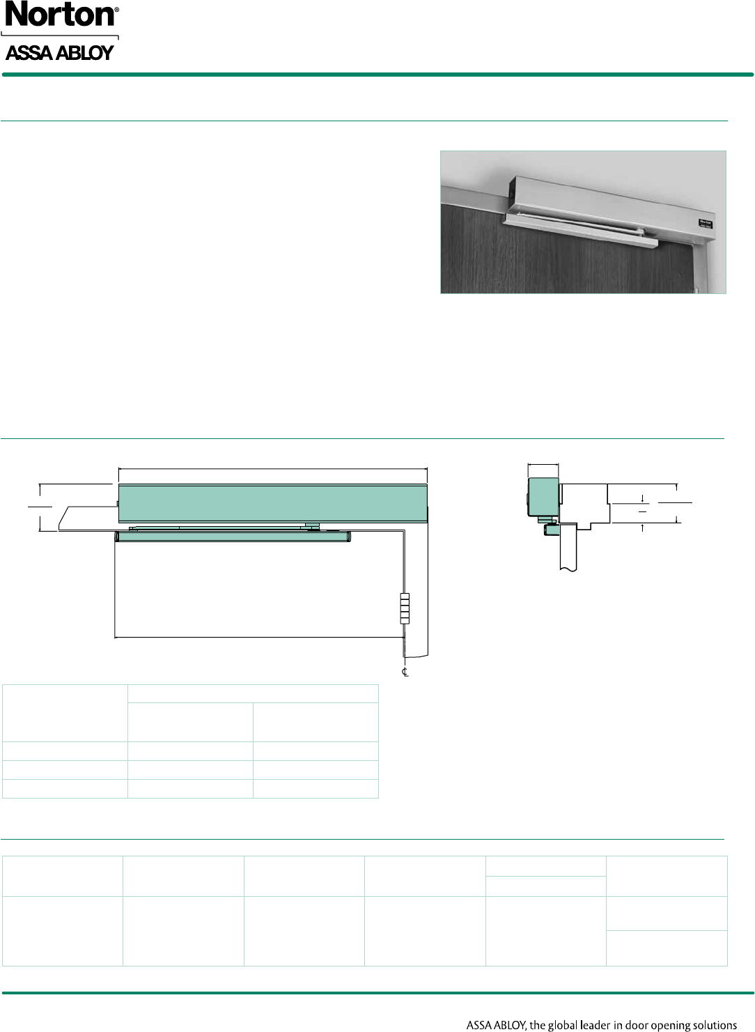
• Surface mounted to the push (stop) frame face
• Double lever arm mounts directly to the door
• Minimum 4" (102mm) ceiling clearance required
• Handed
• Standard units accommodate doors opening 180°; maximum 175° hold open
• Units shipped Selective Hold Open; Infinite Hold Open can be set in the field.
• Fail Safe – solenoid will de-energize in the event of power failure
• Accommodates either concealed or surface wiring
Single Doors:
• Master Units with Integral Smoke Detector:
Both Series 7220MPDO, 7230MPDO are self-contained and can be installed to control a single door.
• Executive™ Door Holder/Release:
Both Series 7220RFS, 7230RFS are self-contained and can be installed to control a single door.
Pairs of Doors:
• Master Unit x Slave/Support Unit: Smoke Detector in the Master Unit controls the Closer/Holder in both the Master Unit and the
Slave/Support Unit.
7220MPDO Shown
26-11/16
(677)
2"
(50)
2-11/16"
(68)
2"
(50)
3-1/2
(89)
Min
Reveal
7220/7230
Note: For applications with narrow top rails or limited ceiling clearance, a special drop angle bracket is required. See page 15.
7200 SERIES
ElEctRomEchanIcal cloSER/holdER
10
DOOR SIZE
Copyright © 2005-2016, Yale Security Inc., an ASSA ABLOY Group company. All rights reserved.
Reproduction in whole or in part without the express written permission of Yale Security Inc. is prohibited.
ELECTRICAL DATA
Master Units
Series
Number Suffix Operating
Voltage (Input)
No. Power Input
Lines* (Pairs)
Amperage Draw (Can be) Used
with Master
Unit
Smoke Detector Solenoid
Coil
Standby Alarm
7220
7230 MPDO
24VDC
1.016@
24VDC
.035@
24VDC
.070@
24VDC
7220MPSO
7230MPSO
120VAC
Executive™ Door Holder Release
Series
Number
Operating Volage
(Input)
No. Power Input
Lines* (Pairs)
Amperage Draw
Solenoid Coil
7220RFS
7230RFS
120VAC
1.070@
24VDC
24VDC
Maximum
Door Size
(cm)
Model Number Maximum
Degree of
Opening
Reveal Range
(Inches/mm)
Closer/Holder Executive™
Door/Release
42" (107)
7223MPDO 7223RFS
180° 2-3/4" - 4"
(70 - 102)
165° 4" - 7"
(102 - 178)
7233MPDO 7233RFS 180°
48" (122)
7224MPDO 7224RFS
180° 2-3/4" - 4"
(70 - 102)
165° 4" - 7"
(102-178)
7234MPDO 7234RFS 180°
Note: Contact factory if door weight exceeds 250 lbs.
*Max/Min Operating Voltage Parameters +10%/-15%

11
SLAVE/SUPPORT UNITS
Copyright © 2005-2016, Yale Security Inc., an ASSA ABLOY Group company. All rights reserved.
Reproduction in whole or in part without the express written permission of Yale Security Inc. is prohibited.
7200 SERIES
ElEctRomEchanIcal cloSER/holdER
Maximum
Door Size
(cm)
Model Number Maximum Degree
of Opening
Reveal Range
(Inches/mm)
42"
(107)
7223MPSO 180° 2-3/4" - 4"
(70-102)
165° 4"-7"
(102-178)
7233MPSO 180°
48"
(122)
7224MPSO 180° 2-3/4" - 4"
(70-102)
165° 4"-7"
(102-178)
7234MPSO 180°
Note: Contact factory if door weight exceeds 250 lbs.
TECHNICAL DETAILS
DOOR SIZE
ELECTRICAL DATA
7220/7230
• Surface mounted to the push (stop) frame face
• Double lever arm mounts directly to the door
• Minimum 4" (102mm) ceiling clearance required
• Handed
• Standard units accommodate doors opening 180°; maximum 175° hold open
• Units shipped Selective Hold Open; Infinite Hold Open can be set in the field.
• Fail Safe – solenoid will de-energize in the event of power failure
• Accommodates either concealed or surface wiring
Pairs of Doors:
• Master Unit x Slave/Support Unit: Smoke Detector in the Master Unit controls the Closer/Holder in both the Master Unit
and the Slave/Support Unit.
7220MPSO Shown
4
(102)
2
(51)
2-5/8
(67)
2-1/8
(54)
Reveal
25-5/8
(651)
3-1/2
(89)
Min
Model
Number Suffix Operating Voltage
(Input)
No. Power Input
Lines* (Pairs)
Amperage Draw (Can be) Used with
Master Unit
Solenoid Coil
7220
7230 MPSO
24VDC (only)
24VDC Supplied from
Master Unit
1.070@
24VDC
7220MPDO-24
7230MPDO-24
7220MPDO-120
7230MPDO-120
*Max/Min Operating Voltage Parameters +10%/-15%
Note: For applications with narrow top rails or limited ceiling clearance, a special drop angle bracket is required. See page 15.
7200 SERIES
ElEctRomEchanIcal cloSER/holdER
12
7240 CONNECTED FREE SWING ARM
Copyright © 2005-2016, Yale Security Inc., an ASSA ABLOY Group company. All rights reserved.
Reproduction in whole or in part without the express written permission of Yale Security Inc. is prohibited.
The connected free swing arm assembly provides the convenient automatic closing fire door
protection for health care facilities or other locations where it is desired to neutralize the effort
required to open or close a door. With no spring force on the door during the normal operation,
patients, the handicapped and/or staff find the door easy to open, close or leave ajar.
Functions:
• Arm driver connected to the closer pinion drives the pinion when the door is opened and the
slide arm rotates.
• When unit is energized the pinion and arm driver remain at the point where door was initially
opened.
• Arm is connected to the pinion but is free to pivot.
• The door is free to open, close or be set at any degree of opening.
• When there is a Fire/Smoke alarm or any power interruption, the hold open control valve is
released, and door closes.
• Units shipped Selective Hold Open; Infinite Hold Open can be set in the field.
UL Listed:
7200 Series with Connected Free Swing arm is UL listed as a releasing device for Fire/Smoke
Barrier doors.
Specify voltage and hand of door when ordering
Note: Contact factory if door weight exceeds 250 lbs.
As the door is opened,
the rigid slide arm
rotates the arm driver
and the pinion shaft of
the closer mechanism.
When the door has been opened
and released, the unit’s electrically
controlled plunger valve will hold
the pinion shaft and arm driver
at that degree of door opening.
The door is then free to swing
unhindered.
After Fire/Smoke detection alarm or
any power interruption to the control,
the pinion shaft and arm driver are
released to close the door.
Maximum
Door Size
(cm)
Model Numbers
Master Slave/Support Executive™ Door Release
Selective Hold Open
40" (102) 7243MPDO 7243MPSO 7243RFS
44" (112) 7244MPDO 7244MPSO 7244RFS
48" (122) 7245MPDO 7245MPSO 7245RFS
Door free
swing
Door close
13
7290 OVERHEAD CONCEALED SUPPORT UNIT
Copyright © 2005-2016, Yale Security Inc., an ASSA ABLOY Group company. All rights reserved.
Reproduction in whole or in part without the express written permission of Yale Security Inc. is prohibited.
7200 SERIES
ElEctRomEchanIcal cloSER/holdER
DOOR SIZE
ELECTRICAL DATA
TECHNICAL DETAILS
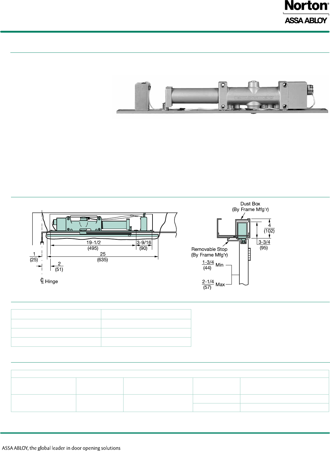
• Handed
• Unit concealed in the header of
the frame
• Installation requires a 4" (102mm) high
frame header
• A 2" x 4" (51 x 102mm) dust/grout
box and a removable frame stop
(provided by the door and frame supplier) are required.
• Slide track is mortised in the door’s top rail
• Standard units accommodate doors opening 180°; maximum 175° hold open
• Buffer block assembly in the track will accommodate doors opening to 125°
• Auxiliary door stop is required for doors opening beyond 125°
• Units shipped Selective Hold Open; Infinite Hold Open can be set in the field.
• Intended for use with compatible UL listed ceiling alarm detection equipment.
• Fail Safe – solenoid will de-energize in the event of power failure
Controlled Remotely by Area/Ceiling Detectors
Maximum Door Size (cm) Selective Hold Open
32" (81) 7294MPS
38" (97) 7295MPS
48" (122) 7296MPS
Support Unit
Model Number Suffix Number power
Input Lines* (pairs)
Operating
Voltage (input) Amperage Draw Solenoid Coil (ampreses)
7290 MPS 1 24VAC/DC .070@24VAC/DC
120VAC .035@120VAC
Note: Contact factory if door weight exceeds 250 lbs.
* Max/Min Operating Voltage Parameters +10%/-15%
7200 SERIES
ElEctRomEchanIcal cloSER/holdER
14
CLOSER BODIES
Copyright © 2005-2016, Yale Security Inc., an ASSA ABLOY Group company. All rights reserved.
Reproduction in whole or in part without the express written permission of Yale Security Inc. is prohibited.
ARM & TRACK ASSEMBLIES
Description Mounting Voltage Hand Part Number
Closer/Holder Assembly Push or Pull 24VDC
Left 720XLAPS24L
Right 720XLAPS24R
Description For Series Part Number
Slide Track 7210, 7240, 7250 7100-IT
Slide Arm 7210 7110-1A
Connected Free Swing Arm 7240 7140-1A
Double Egress Arm - Right Hand
7250
7150-1R
Double Egress Arm - Left Hand 7150-1L
Double Lever Arm 7220 7701-1A
Double Lever Arm 7230 7701-1B
Arm Assembly NHO - Right Hand
7290
7950-1R
Arm Assembly NHO - Left Hand 7950-1L
Track Assembly NHO 7950ST
15
TRACK & ARM PARTS
Copyright © 2005-2016, Yale Security Inc., an ASSA ABLOY Group company. All rights reserved.
Reproduction in whole or in part without the express written permission of Yale Security Inc. is prohibited.
7200 SERIES
ElEctRomEchanIcal cloSER/holdER
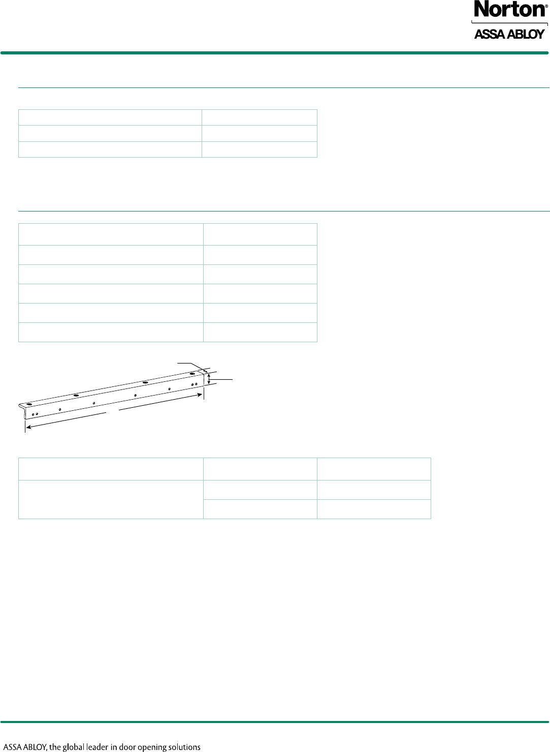
MISCELLANEOUS PARTS
Description Part Number
Cushion Block (part of slide track assembly) 7100CB
Screw Pack for CFS Arm 7240SP
Description Part Number
Smoke Detector Board MPDOSD24
Cover (Slave/Support Unit) MPSOCOV
Cover (Master Units) MPDOCOV
Selective Hold Open Switch Assembly 24V SHOK
Switch 24V SHO
A
1-1/2"
(38)
1-1/2"
(38)
Description Part Number A
(Length)
Drop Angle Bracket
7100DAB 29-9/16" (675)
7100DAB-180 24-9/16" (621)

7200 SERIES
ElEctRomEchanIcal cloSER/holdER
contact us at:
Norton Door Controls
3000 Highway 74 East
Monroe, NC 28112
Tel: 877-974-2255
Fax: 800-338-0965
ASSA ABLOY Door Security Solutions Canada
160 Four Valley Drive
Vaughan, Ontario, L4K 4T9 Canada
Tel: 800-461-3007
Fax: 905-738-2478
For a complete listing of products and
applications please visit our web site.
www.nortondoorcontrols.com
www.assaabloy.ca
Norton® is a registered trademark of Yale Security Inc., an ASSA ABLOY Group company. Executive™ is a trademark of Yale Security Inc., an ASSA ABLOY Group company. Other products' brand
names may be trademarks or registered trademarks of their respective owners and are mentioned for reference purposes only. These materials are protected under U.S. copyright laws. All contents current
at time of publication. Copyright © 2005-2016, Yale Security Inc., an ASSA ABLOY Group company. All rights reserved. Reproduction in whole or in part without the express written permission of Yale Security
Inc. is prohibited.
43063-1/16R
