Novatel Wireless GSM2374 GSM/ GPRS OBD Vehicle Tracker User Manual GSM2374UG001 MT 3000 User Guide
Novatel Wireless Inc. GSM/ GPRS OBD Vehicle Tracker GSM2374UG001 MT 3000 User Guide
User Manual

MT 3000
User Guide
GSM2374UG001
Version:1.00
23 February, 2011
General
TERMS OF USE OF NEW MATERIALS - PLEASE READ CAREFULLY
From time to time, Enfora, in its sole discretion, may make available for download on its website
(www.enfora.com), or may transmit via mail or email, updates or upgrades to, or new releases of, the
firmware, software or documentation for its products (collectively, 'New Materials'). Use of such New
Materials is subject to the terms and conditions set forth below, and may be subject to additional terms
and conditions as set forth in Enfora's Technical Support Policy (posted on its website) and/or any written
agreement between the user and Enfora.
All New Materials are provided AS IS. Enfora makes no warranty or representation with respect to the
merchantability, suitability, functionality, accuracy or completeness of any such New Materials. The user of
such New Materials assumes all risk (known or unknown) of such use. Enfora reserves all rights in such
New Materials. The user shall have only a revocable and limited license to use such New Materials in
connection with the products for which they are intended. Distribution or modification of any New
Materials without Enfora's consent is strictly prohibited.
IN NO EVENT WILL ENFORA BE RESPONSIBLE FOR ANY INCIDENTAL, INDIRECT, CONSEQUENTIAL OR
SPECIAL DAMAGES AS A RESULT OF THE USE OF ANY NEW MATERIALS. ENFORA'S MAXIMUM LIABILITY
FOR ANY CLAIM BASED ON THE NEW MATERIALS SHALL NOT EXCEED FIFTY U.S. DOLLARS ($50).
Copyright
© 2011 Enfora, Inc. All rights reserved. Complying with all applicable copyright laws is the responsibility of
the user. Without limiting the rights under copyright, no part of this document may be reproduced, stored
in or introduced into a retrieval system, or transmitted in any form or by any means (electronic,
mechanical, photocopying, recording or otherwise), or for any purpose, without the express written
permission of Enfora, Inc.
Enfora and the Enfora logo are either registered trademarks or trademarks of Enfora, Inc. in the United
States.
251 Renner Pkwy
Richardson, TX 75080 USA
Phone: (972) 633-4400
Fax: (972) 633-4444
Email: info@enfora.com
www.enfora.com
- I -
Warranty Information
[Revised: 11/11/2010]
This warranty applies to (a) products sold directly by Enfora, unless a different warranty is specified in a
written agreement between Enfora and the purchaser; and (b) products sold to end users through a
distributor authorized by Enfora, but only where the authorized distributor does not provide a separate
warranty on such products, and Enfora has agreed to provide this warranty to such end users. If you
purchased the product from an authorized distributor, please check whether this warranty from Enfora, or
a separate warranty from the distributor, applies to your purchase. This warranty does not apply to any (i)
accessories or batteries for the products; or (ii) demonstration samples or prototypes of the products.
Unless otherwise provided in a written agreement between Enfora and the purchaser, all such accessories,
batteries, samples or prototypes are provided by Enfora AS IS without any warranty of any kind.
Enfora warrants to the original purchaser of the product from Enfora or its authorized distributor (as
applicable) that, for a period of one (1) year from the date of shipment of the product from Enfora, the
product hardware will be substantially free from defects in material or workmanship under normal
operation, and the product firmware will perform substantially in accordance with the product
documentation provided by Enfora. Enfora does not warrant that (a) the product hardware or firmware
will meet the purchaser's requirements; (b) the operation of the product hardware or firmware will be
uninterrupted or error-free; or (c) the product, when integrated in, or combined with, other products or
software not supplied by Enfora, will continue to perform substantially in accordance with the product
documentation. This limited warranty is for the benefit of the original purchaser, and is not transferable.
During the warranty period, Enfora, at its expense and in its sole discretion, will repair the product, or
replace the product with a corresponding or equivalent product, if it is determined to have a covered
defect, provided that the purchaser first notifies Enfora (directly or through its authorized distributor from
which the product was purchased) of any such defect, furnishes Enfora with a proof of purchase (if
required), requests and obtains a return merchandize authorization (RMA) number from Enfora, and
returns the product under that RMA to Enfora (or, at Enfora's option, to its authorized distributor), with the
shipping charges being prepaid by purchaser.If, upon reasonable examination of the returned product,
Enfora does not substantiate the defect claimed by purchaser, or determines that the defect is not covered
under this limited warranty, Enfora will not be required to repair or replace the product, but may instead
reship the product to the purchaser (or, at Enfora's option, to its authorized distributor where the product
can be made available to purchaser), in which case the purchaser shall be responsible for paying Enfora's
cost for reshipping the product to purchaser (or to Enfora's authorized distributor), and Enfora's usual
charges for unpacking, testing, and repacking the product for reshipment to purchaser (or to Enfora's
authorized distributor). Purchaser shall bear the risk of loss or damage in transit to any product returned
by purchaser to Enfora, or any returned product not found to be defective or covered under this warranty,
and reshipped by Enfora to purchaser (or to Enfora's authorized distributor). In the event Enfora repairs or
- II -
replaces a defective product covered by this limited warranty, the repaired or replacement product will be
covered under this limited warranty for the remainder of the original warranty period on the defective
product, or a period of ninety (90) days, whichever is longer. If Enfora is unable to repair or replace a
defective product covered by this limited warranty, Enfora will provide to purchaser a credit or a refund
(at Enfora's option) of the original purchase price (excluding taxes and shipping charges). Any returned and
replaced product, or any product for which Enfora has furnished a credit or a refund, becomes the
property of Enfora.
Enfora shall not have any obligation to provide any firmware bug fixes, upgrades or new releases except as
may be necessary to correct any covered defect of which purchaser notifies Enfora in writing during the
warranty period. Enfora, from time to time and in its sole discretion, may make available for download on
its website (www.enfora.com), or may provide via email, certain firmware bug fixes, upgrades or new
releases for the product. Download and use of any such bug fixes, upgrades or new releases is subject to all
of the applicable terms and conditions of Enfora's technical support policy as posted and updated on its
website. Enfora shall have no obligation under this limited warranty for (a) normal wear and tear; (b) the
cost of procurement of substitute products; or (c) any defect that is (i) discovered by purchaser during the
warranty period but for which purchaser does not request an RMA number from Enfora, as required
above, until after the end of the warranty period, (ii) caused by any accident, misuse, abuse, improper
installation, handling or testing, or unauthorized repair or modification of the product, (iii) caused by use of
any materials not supplied by Enfora, or by use of the product other than in accordance with its
documentation, or (iv) the result of electrostatic discharge, electrical surge, fire, flood or similar causes.
The purchaser (or its customers, as applicable) shall be solely responsible for the proper configuration,
testing and verification of the Enfora product prior to deployment in the field, and for ensuring that any
end user product or system into which the Enfora product is integrated or incorporated operates as
intended and meets the requirements of purchaser (or its customers). Enfora shall have no responsibility
whatsoever for the integration, configuration, testing, verification, installation, upgrade, support or
maintenance of any such end user product or system, or for any liabilities, damages, costs or expenses
associated therewith.
ENFORA'S SOLE RESPONSIBILITY AND PURCHASER'S SOLE REMEDY UNDER THIS LIMITED WARRANTY
SHALL BE FOR ENFORA TO REPAIR OR REPLACE THE PRODUCT (OR IF REPAIR OR REPLACEMENT IS NOT
POSSIBLE, PROVIDE A CREDIT OR REFUND OF THE PURCHASE PRICE) AS PROVIDED ABOVE. ENFORA
EXPRESSLY DISCLAIMS ALL OTHER WARRANTIES OF ANY KIND, EXPRESS OR IMPLIED, INCLUDING
WITHOUT LIMITATION ANY IMPLIED WARRANTIES OF NON- INFRINGEMENT, MERCHANTABILITY,
SATISFACTORY PERFORMANCE AND FITNESS FOR A PARTICULAR PURPOSE. IN NO EVENT SHALL ENFORA
BE LIABLE FOR ANY INDIRECT, SPECIAL, EXEMPLARY, INCIDENTAL OR CONSEQUENTIAL DAMAGES
(INCLUDING WITHOUT LIMITATION LOSS OR INTERRUPTION OF USE, DATA, REVENUES OR PROFITS)
RESULTING FROM A BREACH OF THIS WARRANTY OR BASED ON ANY OTHER LEGAL THEORY, EVEN IF
ENFORA HAS BEEN ADVISED OF THE POSSIBILITY OR LIKELIHOOD OF SUCH DAMAGES.
- III -
Some jurisdictions may require a longer warranty period than specified above and, accordingly, for
products sold in those jurisdictions the applicable warranty period shall be extended as required under the
laws of those jurisdictions. Furthermore, some jurisdictions may not allow the disclaimer of implied
warranties or the exclusion or limitation of incidental or consequential damages, so the above disclaimer,
limitation or exclusion may not apply to products sold in those jurisdictions. This limited warranty gives the
purchaser specific legal rights and the purchaser may have other legal rights that vary from jurisdiction to
jurisdiction. This limited warranty shall be governed by the laws of the State of Texas, United States of
America, without regard to conflict of laws principles. This limited warranty shall not be governed in any
respect by the United Nations Convention on Contracts for the International Sale of Goods.
Regulatory Compliance
FCC
FCC ID: MIVGSM2374
This device complies with Part 15 of the FCC Rules. Operation is subject to the following two conditions: (1)
This device may not cause harmful interference, and (2) this device must accept any interference received,
including interference that may cause undesired operation.
This equipment has been tested and found to comply with the limits pursuant to Part 15 Subpart B, Part 22,
and Part 24 of the FCC rules. These limits are designed to provide reasonable protection against harmful
interference in an appropriate installation. This equipment generates, uses, and can radiate radio
frequency energy and, if not used in accordance with instructions, can cause harmful radiation to radio
communication. However, there is no guarantee that interference will not occur in a particular installation.
FCC RF EXPOSURE
Your MT 3000 is a radio transmitter and receiver. It is designed and manufactured not to exceed the
emissions limits for exposure to radio frequency (RF) energy set by the Federal Communications
Commission (FCC) of the U.S. Government. These limits are part of comprehensive guidelines and establish
permitted levels of RF energy for the general population. These guidelines are based on the safety
standards previously set by the U.S. and international standards bodies. The standards include a substantial
safety margin designed to assure the safety of all persons, regardless of age and health.
The exposure standard for wireless RF devices, such as the MT 3000, employs a unit of measurement
known as the Specific Absorption Rate, or SAR. The SAR limit set by the FCC is 1.6W/kg. SAR values at or
below that limit are considered safe for the general public.
- IV -
The MT 3000 conforms with the RF exposure requirements for portable devices in accordance with FCC
Part 2.1093.
The MT 3000 transmitter is configured with a 10% transmission duty factor, for GPRS Multislot class 2
operation, and is excluded from routine RF exposure evaluation in accordance with FCC Mobile and
Portable Device RF Exposure Procedures and Equipment Authorization Policies, KDB447498 D01, V04.
Canadian Compliance (Industry Canada)
IC ID: 4160A-GSM2374 MODEL NUMBER: GSM2374
This device complies with Industry Canada licence-exempt RSS standard(s). Operation is subject to the
following two conditions: (1) this device may not cause interference, and (2) this device must accept any
interference, including interference that may cause undesired operation of the device.
The MT 3000 transmitter is configured with a 10% transmission duty factor, for GPRS Multislot class 2
operation, and is excluded from routine RF exposure evaluation in accordance with the requirements of
RSS-102 section 2.5.
Le présent appareil est conforme aux CNR d'Industrie Canada applicables aux appareils radio exempts de
licence. L'exploitation est autorisée aux deux conditions suivantes : (1) l'appareil ne doit pas produire de
brouillage, et (2) l'utilisateur de l'appareil doit accepter tout brouillage radioélectrique subi, même si le
brouillage est susceptible d'en compromettre le fonctionnement.
L'émetteur de 3000 MT est configuré avec un facteur d'obligation de transmission de 10 %, pour GPRS
Multislot opération de classe 2 et est exclu de l'évaluation de l'exposition RF conformément aux exigences
du CNR-102 article 2.5 de la routine.
ROHS COMPLIANCE
The MT 3000 complies with the European Union Restriction of the Use of Certain Hazardous Substances in
Electrical and Electronic Equipment ([RoHS) Directive (2002/95/EC), effective since July 1, 2006..
DISCLAIMER
The information and instructions contained within this publication comply with all applicable FCC, GCF,
PTCRB, R&TTE, IMEI and other applicable codes that are in effect at the time of publication. Enfora
disclaims all responsibility for any act or omissions, or for breach of law, code or regulation, including local
or state codes, performed by a third party. Enfora strongly recommends that all installations, hookups,
- V -
transmissions, etc., be performed by persons who are experienced in the fields of radio frequency
technologies. Enfora acknowledges that the installation, setup and transmission guidelines contained within
this publication are guidelines, and that each installation may have variables outside of the guidelines
contained herein. Said variables must be taken into consideration when installing or using the product, and
Enfora shall not be responsible for installations or transmissions that fall outside of the parameters set
forth in this publication.
- VI -

Table of Contents
1 Introduction 1
1.1 Objective 1
1.2 References 2
1.3 On-Board Diagnostics Overview 2
2 Overview 4
2.1 Description 4
MT 3000 Panel Illustrations 4
2.2 Barcode Label 5
2.3 Connector & LEDs 5
2.4 Accelerometer 6
2.5 GSM Radio 6
2.6 Packet Data 7
2.7 GPS Functionality 7
3 Hardware Features 8
3.1 Opening The Device 8
3.2 Closing the Device 13
3.3 SIM Card Access 14
3.4 Power 15
3.5 Micro USB 15
4 Software Features 17
AT Commands Over SMS 17
Store/Transmit Event Data 17
Synchronize RTC Time with GPS Time 17
4.1 New Event Reporting 17
Vehicle Identification Number (VIN) 17
Excessive Engine Speed (RPM) 18
- VII -

Vehicle Speed 18
Vehicle Battery Voltage (Low Battery Warning) 18
Check Engine Light (MIL Alert) 19
Trip Odometer Reporting 19
Idle Time Reporting 19
Low Fuel Alert 19
Rapid Acceleration 19
Sudden Deceleration (Harsh Braking) 20
Motion Detection 20
OBDII Basic Event Data 20
5 Installation 21
5.1 Inserting the SIM 21
5.2 Device Installation 22
5.3 Accelerometer Calibration 23
6 Network Test Procedure 24
6.1 Configuration 24
6.2 Equipment Needed 24
6.3 Configure the Computer and Verify Correct Communications 24
Configure the Device to Communicate with the Enfora Server 24
6.4 Verifying Server Connectivity 30
6.5 Verify GPS Operation 33
- VIII -

Table of Figures
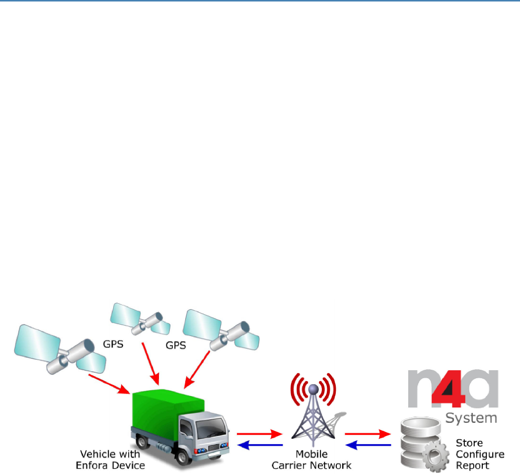
Figure: 1 - N4A System Overview 1
Figure: 2 - Front Right View 4
Figure: 3 - Bottom Left View 4
Figure: 4 - MT 3000 Label 5
Figure: 5 - MT 3000 Connector and LEDs 5
Figure: 6 - MT 3000 Opening Toolkit 8
Figure: 7 - MT 3000 9
Figure: 8 - Lever inserted into MT 3000 lid gap 9
Figure: 9 - MT 3000 with Lid unsnapped 10
Figure: 10 - MT 3000 on the Opener Base 11
Figure: 11 - Lid pulled away from the MT 3000 12
Figure: 12 - MT 3000 with Lid completely removed 12
Figure: 13 - MT 3000 without Lid 13
Figure: 14 - Replacing the MT 3000 Lid 14
Figure: 15 - Internal SIM Holder 15
Figure: 16 - Micro USB Cable 16
Figure: 17 - Internal SIM Holder 21
Figure: 18 - Typical OBDII Socket Location 23
Figure: 19 - ATI Response 25
Figure: 20 - Verify GPRS Status 27
Figure: 21 - Verify GPRS Activation 28
Figure: 22 - Wakeup Command 30
Figure: 23 - Verify Server Connectivity 31
Figure: 24 - Wakeup Messages 32
Figure: 25 - ATI Response 33
Figure: 26 - Verify GPS Operation 34
- 9 -

Table of Tables
Table: 1 - MT 3000 LEDs 6
- 10 -
1 Introduction
1.1 Objective
The objective of this document is to provide the user with basic information about the Spider MT Series,
including how to configure the device and verify communication with Enfora’s UDP API test server.
Capabilities of the Enfora Spider MT devices include:
lGSM Registration
lGPRS Registration
lVelocity
lGeo-Fence
lIP Status
lGPS Status
lTimer
lMT Power Save
lRTC Alarm
lMemory Full Percentage
lInput Event Counter
lGPS Overspeed
lMessage Log Count
lSMS Indication
lGPS Distance
Figure: 1 - N4A System Overview
-1-

1.2 References
lSpider MT 3000 AT Command Set (GSM2374AT001)
lGSM Network Configuration Worksheet (GSM0000AN019)
lMobile Tracker Event Cookbook (GSM2000CB001)
1.3 On-Board Diagnostics Overview
An On-Board Diagnostics (OBD) system controls engine functions and serves as the diagnostic control
network of the vehicle. All cars built and sold in the United States since 1996 must be equipped with the
newer OBDII system. The Enfora MT 3000 connects to a vehicle's OBDII port and monitors the OBDII
system using a variety of communication protocols.
The MT 3000 can be configured to provide notification messages based on engine rpm, low fuel or battery,
or other events monitored by the OBDII system in addition to events triggered by the device's
accelerometer or GPS information.
Some vehicles are not compatible with the MT 3000. If the vehicle is not compatible
with the parameters the MT 3000 requires, functionality my be limited, problematic
or unavailable.
The SAE (Society of Automobile Engineers) 1979 standard defines the method for requesting diagnostics
data and a list of standard parameters from the engine control unit.
Compliance to this standard is the responsibility of the vehicle manufacturer, therefore Enfora cannot
guarantee performance of the MT 3000 with every vehicle.
The following are some of the OBDII parameters monitored by the Enfora MT 3000 and triggered as alerts
when so configured:
lVehicle Identification Number (VIN)
lExcessive engine speed (RPM)
lVehicle speed
lVehicle battery voltage (low battery warning)
lCheck engine light (MIL alert)
lOdometer (trip distance)
lIdle time
lLow fuel
-2-

The MT 3000 supports the following standard OBDII protocols:
lJ1850 PWM
lJ1850 VPW
lISO-9141-2
lISO-14230 KWP2000
lISO-15765 CAN
Some vehicles only support a subset of these protocols, in these cases functionality of
the MT 3000 will be limited.
-3-
2 Overview
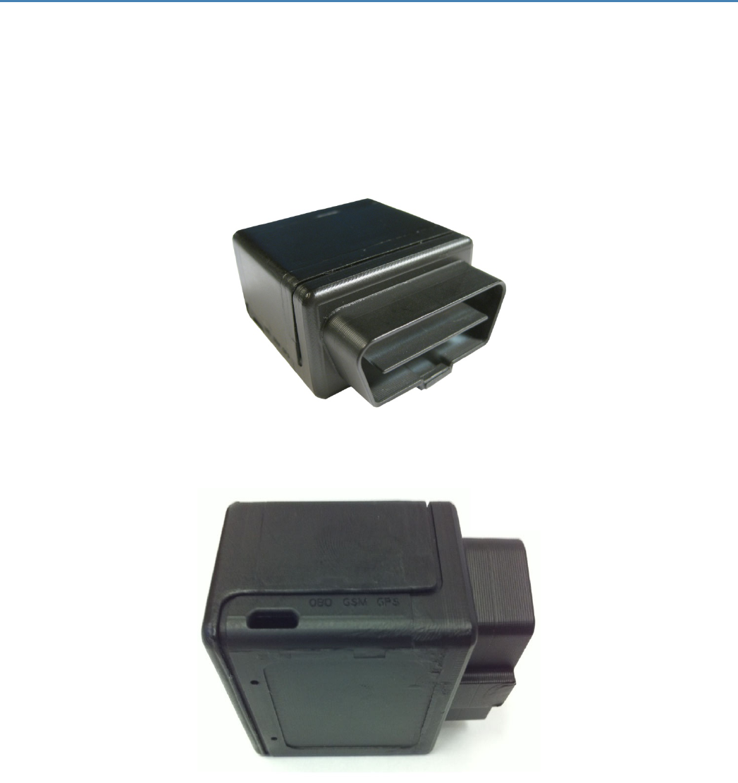
2.1 Description
The MT 3000 has a rugged plastic housing that measures 46 x 43 x 28 mm. It contains internal GSM and
GPS antennas, internal SIM card holder, J1962 complaint OBDII connector, micro USB connector, and 3 LED
indicators.
MT 3000 Panel Illustrations
Figure: 2 - Front Right View
Figure: 3 - Bottom Left View
- 4 -
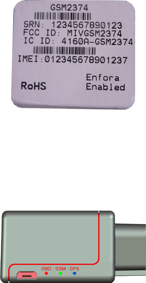
2.2 Barcode Label
The barcode label is located on the underside of the device.
Figure: 4 - MT 3000 Label
2.3 Connector & LEDs
The MT 3000 includes a J1962 compliant OBDII connector, a micro USB I/O port, and LEDs to indicate OBD
II, GSM, and GPS status.
The following figure shows the MT 3000 connector and LEDs.
Figure: 5 - MT 3000 Connector and LEDs
-5-
The following table describes the LED operation.
MT 3000 LEDs
OBD The OBD LED will flash at a fast rate when the unit is first connected to the OBD port for power.
Once a protocol is discovered through the OBD port, the LED will flash at a slow rate.
GSM The GSM LED will flash at a fast rate when the unit is finding cellular coverage. Once cellular
coverage is found, the LED shall flash at a slow rate. While the unit is transmitting, the LED is lit
continuously.
GPS The GPS LED will flash at a fast rate when the unit is acquiring a satellite fix. Once a fix is acquired,
the LED will flash a slow rate.
Table: 1 - MT 3000 LEDs
2.4 Accelerometer
The three-axis digital accelerometer provides the following features:
lMotion alert
lDriver behavior reporting
lRapid acceleration
lHarsh braking
lConfigurable thresholds
lRange settings
lMode (Normal, Sleep, Wakeup)
lDevice orientation setup
2.5 GSM Radio
The MT 3000 contains a quad-band (850/900/1800/1900 MHz) GSM radio.
lClass 4 (2W@850/900 MHz)
lClass 1 (1W@1800/1900 MHz)
The MT 3000 has an internal antenna limited to dual band.
-6-
2.6 Packet Data
Packet data characteristics include:
lClass B, Multislot 2
lGSM/GPRS Rel 97
GSM Functionality includes:
lText
lPDU
lMO/MT
lCell Broadcast
2.7 GPS Functionality
GPS functionality includes:
lNMEA update with all data points
lBinary
lBuffered GPS message feature
- 7 -
3 Hardware Features
3.1 Opening The Device
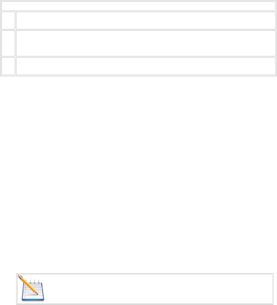
It is highly recommended using the MT 3000 Disassembly Kit (Enfora Part Number KIT2374-01) to remove
the cover of the MT 3000.
The MT 3000 Disassembly Kit includes the Six-Pin Base and the Metal Lever.
Figure: 6 - MT 3000 Opening Toolkit
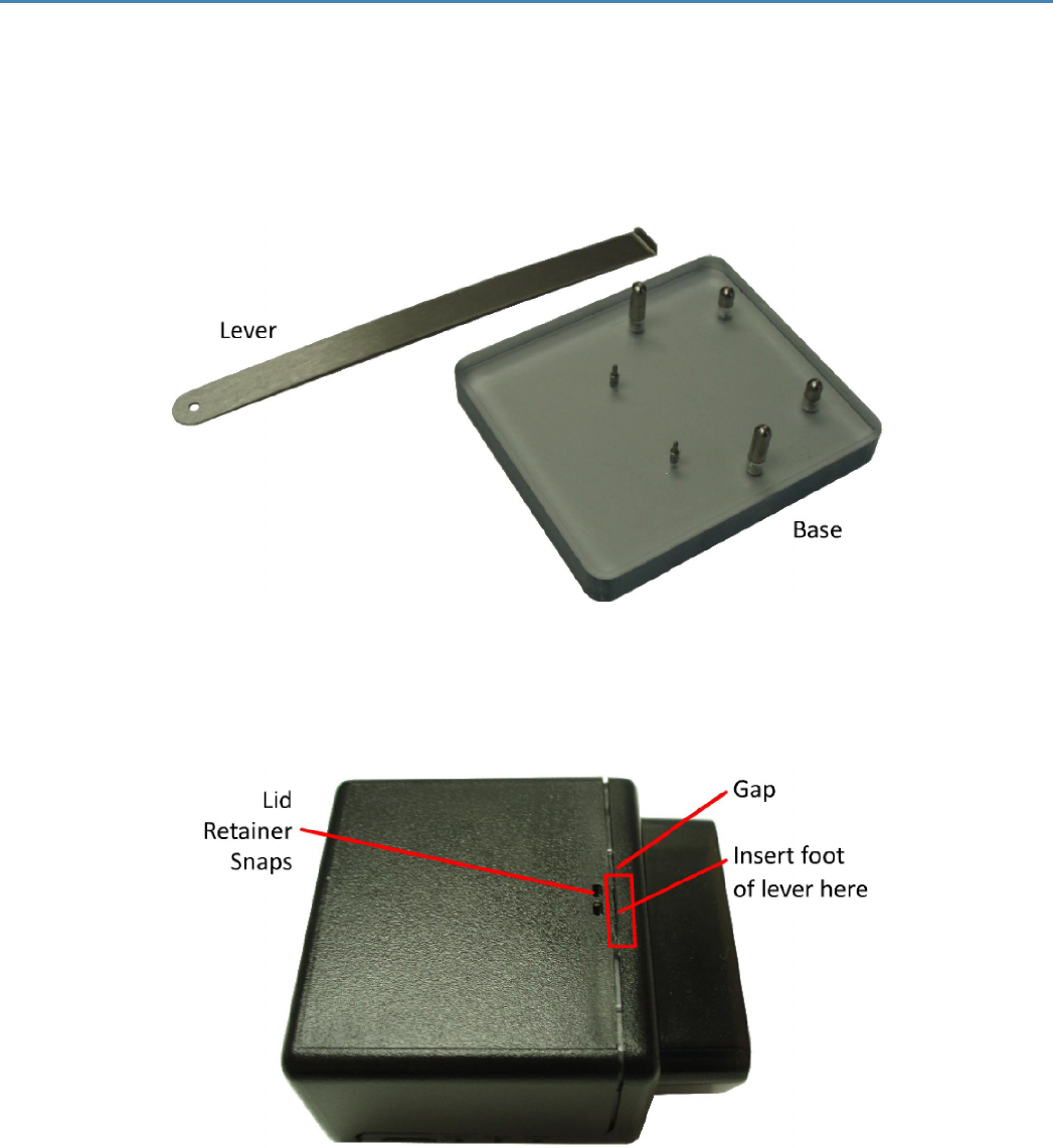
To use the MT 3000 Disassembly Kit, follow the following steps:
1. Insert the curved foot of the Metal Lever into the gap between the lid and the body next to the
retainer snaps.
-8-
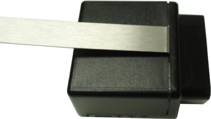
Figure: 7 - MT 3000
2. Gently apply pressure upwards on the lever until the lid unsnaps.
Figure: 8 - Lever inserted into MT 3000 lid gap
-9-
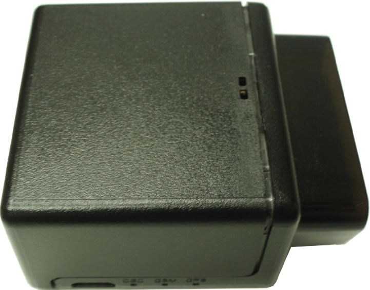
Figure: 9 - MT 3000 with Lid unsnapped
3. Place the MT 3000 into the Base making sure the two small Base Pins are inserted into the two holes
in the base of the MT 3000. The four larger pins fit around the outside of the case and help hold the
MT 3000 in place during the next step.
- 10 -
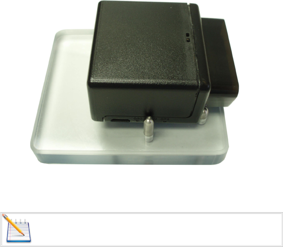
Figure: 10 - MT 3000 on the Opener Base
4. Apply pressure downwards onto the MT 3000 and slide the MT 3000 Lid backwards away from the
rest of the MT 3000.
Downward pressure is required while sliding the lid. Exerting the downward pressure
releases the internal locking clips.
5. Continue sliding the lid away from the MT 3000 untill it completely disengages from the MT 3000.
- 11 -
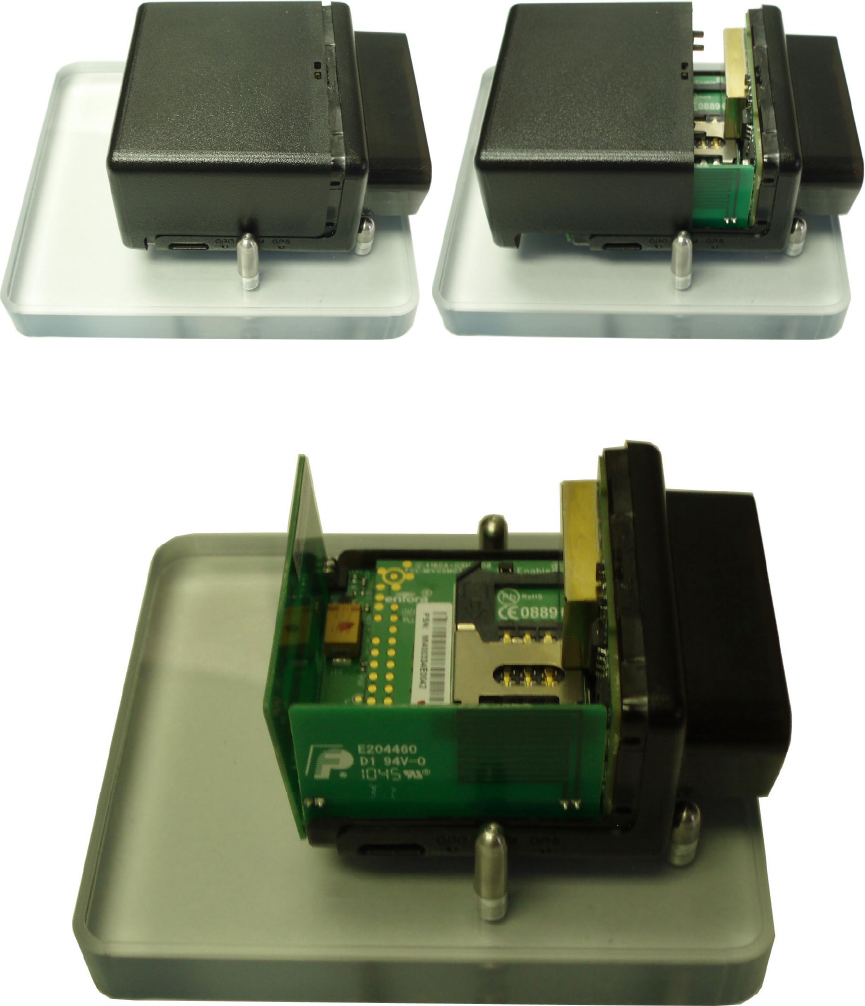
Figure: 11 - Lid pulled away from the MT 3000
Figure: 12 - MT 3000 with Lid completely removed
6. The MT 3000 can now be removed from the Opener Base.
- 12 -
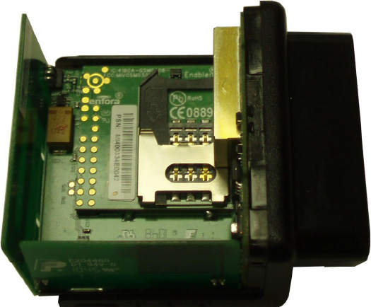
Figure: 13 - MT 3000 without Lid
3.2 Closing the Device
Replace the MT 3000 Lid by using the following steps:
1. Place the MT 3000 Lid onto the base as shown in the following figure.
- 13 -
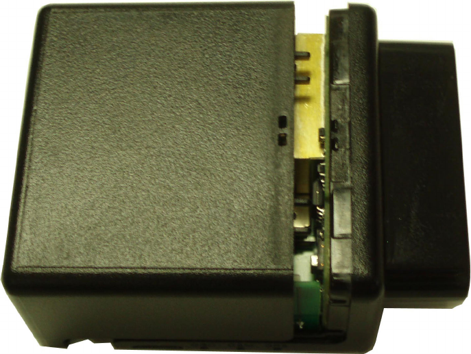
Figure: 14 - Replacing the MT 3000 Lid
2. Carefully slide the lid so that it snaps in place.
3.3 SIM Card Access
The top cover of the MT 3000 unsnaps to provide access to the internal SIM holder.
- 14 -
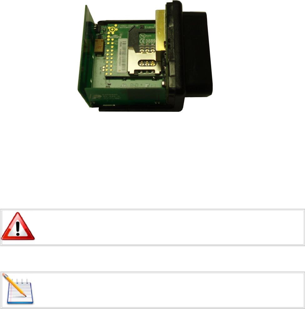
Figure: 15 - Internal SIM Holder
3.4 Power
The Enfora MT 3000 device draws 9-16 Vdc (SAE J1211 compliant) power from the vehicle's OBDII port. No
additional power cabling is required.
3.5 Micro USB
Warning: The Micro USB (2.0) connector is an input/output connector and is not
intended for general use. This connector should only be used when programming the
modem.
Note: This USB port cannot be used to supply power to other USB devices and nothing
should be connected to this port when the vehicle is in motion. The MT3000 can not
be powered through the USBPort.
The micro USB connector is only used to program the modem. When programming the modem, a micro
USB cable is required.
- 15 -
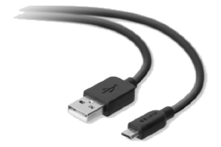
Figure: 16 - Micro USB Cable
- 16 -

4 Software Features
AT Commands Over SMS
A user can send AT commands to the MT 3000 via SMS. Please refer to Enfora Application Note
GSM0308AN001 - Enabler IIIG AT Commands Over SMS.
Store/Transmit Event Data
The user can configure the MT 3000 to store event-generated data in its internal memory, to be sent over
the air to a remote server. This feature can be enabled or disabled using the AT$MSGLOGEN command.
“Total Number of Unread Messages” is decremented if an unread message is read via the AT$MSGLOGRD
command.
Example: Assume there are 50 unread messages in the GPRS queue and the total number of messages in
GPRS queue is 100. This means that the first 50 messages have been read while the last 50 messages have
not been read. If a user sends AT$GPSLOGRD=0,1,51 then the total number of unread messages drops
down to 49 after successful transmission of that message. However, if a user sends AT$GPSLOGRD=0,1,99
then the total number of unread messages still remains at 50 – that message is transmitted to the remote
server.
A user can also read a message that has already been read from the memory by passing in the appropriate
starting index number.
Synchronize RTC Time with GPS Time
The Real Time Clock ("RTC") is synchronized with GPS time automatically every time the device is powered
up and first acquires valid GPS data. Additionally, the RTC time is synched with GPS time every time the
GPS time rolls over from 23:59:59 to 00:00:01.
4.1 New Event Reporting
The MT 3000 has additional event reporting not supported by other Enfora products. For general event
reporting information and for detailed information about these new events refer to the MT 3000 AT
Command Document (GSM2374AT001).
Vehicle Identification Number (VIN)
The VIN is used as a unique identifier, sent at first power up, with heartbeat messages, and with events.
- 17 -

Vehicle manufacturers are responsible for defining the list of data returned,
therefore not all vehicles support retuning the Vehicle Identification Number.
Excessive Engine Speed (RPM)
Excessive engine speed alerts are triggered when the engine speed (in RPM) exceed a defined RPM level
(in ¼ RPM increments) for a defined period of time in seconds (e.g. 30 seconds).
The MT 3000 has three definable thresholds.
Unnecessary wear and tear on the powertrain control module (PCM) may occur if constant or frequent
excessive engine speed is reported. The excessive engine speed event may be caused by one of the
following situations:
lThere are obstructions (ice, mud, etc...) causing wheel slippage that must be cleared from the
vehicle
lThe driver is revving the RPM while in neutral
lThe driver is driving in such a way that the RPM engine speed is deemed excessive, such as speeding
AT$OBDEES=1,16000,3,30
Sets excessive engine speed threshold 1 to 4000 RPM, if exceeded for 3 seconds, trigger input event. This
event will clear once engine RPM is below 4000 for 30 seconds.
Vehicle Speed
If configured for vehicle speed alerts and the vehicle moves faster than one of the three configurable
thresholds (e.g. 70 MPH), then a vehicle speed alert is triggered.
AT$OBDSPD=1,112,10,104
Sets Vehicle Speed Threshold 1 to 112 KPH (~70MPH). If Threshold excededed for 10 seconds trigger input
event. This event will clear when vehicle speed is reduced to 104KPH (~65MPH).
Vehicle Battery Voltage (Low Battery Warning)
The vehicle battery voltage alert is triggered when the vehicle’s battery is reported to be below a threshold
(e.g. 10.7 V) for a user-defined period of time in seconds (e.g. 300 seconds).
AT$OBDLBL=10800,300,300
- 18 -

Sets low battery threshold to 10.8volts. If below this threshold for 300 seconds (5 minutes) trigger the input
event. restoring voltage abovethe threshold for 300secods (5 minutes) will clear this event.
Check Engine Light (MIL Alert)
When the vehicle “Check Engine” light illuminates, this indicates a vehicle issue that requires attention for
diagnosis and/or repair. This is also known as a Malfunction Indicator Light (MIL). When a MIL issue is
detected through the OBDII protocol, an alert is sent from the device if the device is configured to do so.
Trip Odometer Reporting
Trip odometer reporting provides the odometer miles accumulated from ignition on to ignition off, which
is considered a “trip”.
NOTE: Ignition events are not yet detected on hybrid or electric vehicles.
Idle Time Reporting
Idle time event is triggered when the vehicle’s engine is running without the vehicle moving (i.e. velocity
less than 2 MPH) for a defined period of time in seconds (e.g. 300 seconds).
The alert is cleared when the vehicle speed exceeds another speed and time threshold.
Both the violation and clearing of the alert are reported if configured.
AT$OBDLBL=10800,300,300
Sets low battery threshold to 10.8volts. If below this threshold for 300 seconds (5 minutes) trigger the input
event. restoring voltage abovethe threshold for 300secods (5 minutes) will clear this event.
Low Fuel Alert
The low fuel alert triggers when the vehicle’s fuel level falls below a defined threshold in percent (e.g.
12%) for a defined period of time in seconds (e.g. 60 seconds).
Rapid Acceleration
Rapid acceleration events can be triggered when one of three available vehicle speed thresholds are
exceeded as determined by the accelerometer in milli-Gs (e.g. 0.75) for a defined period of time in
seconds (e.g. 30 seconds).
AT$OBDACL=1,200,1,30
- 19 -
Sets Rapid accel threshold 1 to .2Gs. If this threshold is exceeded for 1 second, trigger the input event. This
event will clear in 30 seconds below this treshold.
Sudden Deceleration (Harsh Braking)
Rapid deceleration events can be triggered when one of three available vehicle speed thresholds are
exceeded as determined by the accelerometer in milli-Gs (e.g. 1.0) for a defined period of time in seconds
(30 seconds).
AT$OBDDCL=1,.500,1,3
Sets Rapid decel threshold 1 to .5Gs. If this threshold is exceeded for 1 second, trigger the input event. This
event will clear in 30 seconds below this treshold.
Motion Detection
Motion alerts for vehicles can be configured to communicate that a vehicle is being towed. Motion
detection based on measuring movement via the accelerometer occurs when the vehicle ignition is off,
and the vehicle is stationary.
A motion alert is triggered when motion defined in milli-Gs is detected for a defined period of time.
OBDII Basic Event Data
Four additional data items can be included with event messages:
lVIN
lFirmware version ($PKG)
lOBD Protocol (i.e. J1850 PWM)
lCellular signal strength (RSSI)
- 20 -
5 Installation
5.1 Inserting the SIM
Insert the SIM per the following procedure:
Note: The SIM card is not provided with the MT 3000 device. The SIM must be
obtained from the GSM/GPRS service provider and must be provisioned by the
operator for data. Always take care to protect the SIM. Without the SIM installed,
MT 3000 modem is not able to communicate on the network.
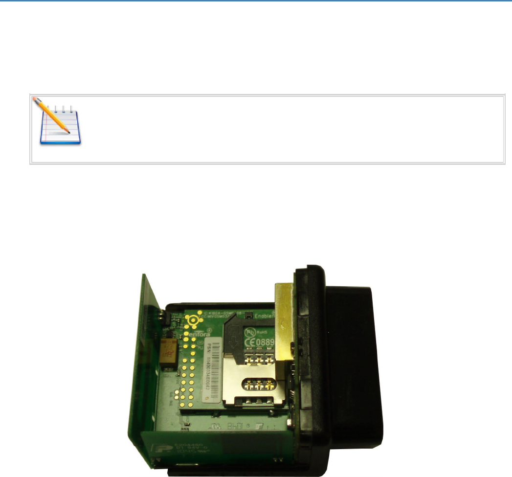
1. Using the correct tool, carefully remove the device cover to access the internal SIM holder.
2. Insert the SIM into the SIM holder of the MT 3000.
3. Replace the cover.
Figure: 17 - Internal SIM Holder
- 21 -
5.2 Device Installation
Instructions provided in this section describe the hardware installation of the MT 3000 device. To install
the MT 3000 in a vehicle, follow these steps:
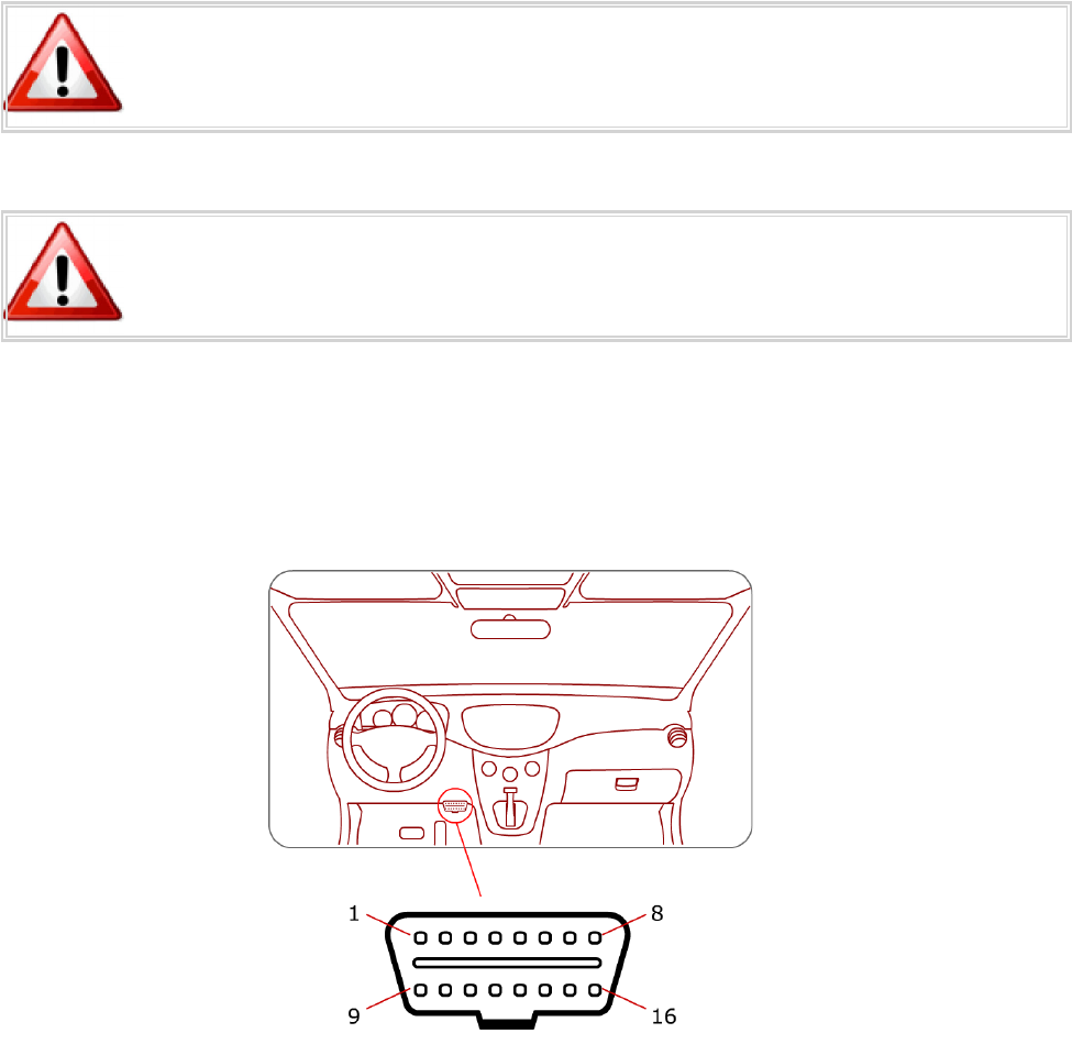
lLocate the OBDII socket. The location will vary between different vehicle manufacturers, models,
and production years.
Do not use this product on '06 or '07 Ford F-150 trucks. Faulty wiring in these vehicles
may cause a fire.
Warning: The MT 3000 is NOT a waterproof or sealed device. Care must be taken to
ensure the device is kept away from water or any other liquids.
l
Carefully insert the MT 3000 into the OBDII socket.
lAfter the device is installed, ensure the device is working properly as evidenced by a GPS lock and cel-
lular connection, which can be validated by the LEDs.
- 22 -

Figure: 18 - Typical OBDII Socket Location
Warning: Upon vehicle ignition on, immediately following device installation, the
device starts the Accelerometer Auto-calibration process.
5.3 Accelerometer Calibration
The accelerometer undergoes an automatic calibration sequence on the first drive after any of the
following events:
lDevice installation
lSoftware upgrade
lVehicle battery replacement (or recharge if battery was fully discharged)
lDevice auxiliary processor reset
Failure to follow the process below will cause could cause an undesired behavior of
the motion feature. Failure to drive straight on level ground during the automatic
calibration may reduce the accuracy of the accelerometer and have an adverse
impact on events triggered by accelerometer readings.
When the vehicle passes 32 KPH, the auxiliary processor assumes that the vehicle is moving in a straight
line and determines the forward axis.
Before installing the MT3000 make sure the vehicle is parked on level ground.
The vehicle should be driven in a straight path on level ground during the automatic calibration. An
inclined surface will put part of the gravity vector into the XY plane, which will affect the acceleration
thresholds. (A 5.7 degree angle will place 10 % of the gravity vector into the XY plane.)
- 23 -
6 Network Test Procedure
6.1 Configuration
The Enfora Mobile Tracker family of products is designed with features to support a robust connection with
the network. However, there can be conditions when the connection to the network or the ability to
transfer data across the network is beyond the control of the device alone.
6.2 Equipment Needed
In this example the requirements are:
lGSM2374 MT 3000
lComputer with one available Serial port or USB-to-serial converter
lGSM/GPRS SIM with GPRS data enabled.
lAn APN (Access Point Name).
lUsername and Password, if GPRS is operating on a non-transparent network.
Note: If you don’t know the name of the APN you need to use, please contact your cellular
network carrier for that information. Once you have acquired this information, please
complete Application Note GSM0000AN019 – GSM Network Configuration Worksheet and
keep this worksheet for future reference.
6.3 Configure the Computer and Verify Correct
Communications
Please refer to Enfora document ENF0001IN001 – USB Installation Guide for detailed instructions for
installing USB drivers and connecting with the modem.
Configure the Device to Communicate with the Enfora Server
- 24 -
Note: In the following instructions, <CR> means using the Enter Key on the keyboard.
1. Connect and verify connectivity with the device.
a. Connect the PC connector to the device.
b. With HyperTerminal open, hit the Enter key. The device should respond with OK. If you do not
see this response, double-check your connections. If the connections seem correct, disconnect
the MT 3000 from the computer and perform a serial loop-back test.
c. Type AT<CR>. The device should respond with OK.
i. If you do not see the letters AT, send the following command to the device:
ii. ATE1<CR>
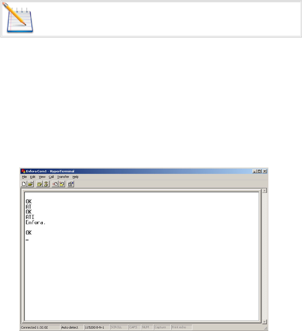
d. Type ATI<CR>. The device should respond with Enfora, Inc. If you get any different response,
you are not connected to the Enfora device. See Figure: 19 - "ATI Response"
Figure: 19 - ATI Response
2. Configure the device to communicate with the Enfora Test Server.
a. The following information will need to be obtained from the SIM provider. Please refer to
GSM0000AN019 – Network Configuration Worksheet.
- 25 -

i. APN
ii. Username and password (If necessary.)
b. Reset the device to factory defaults:
i. To restore the device to factory defaults, send the following command: AT&F<CR>
ii. To write current configuration to memory, send the following command: AT&W<CR>
iii. To reset the device, send the following command: AT$RESET<CR>
c. Configure the device to access the GPRS network.
i. To configure the device with the proper APN, send the following command:
AT+CGDCONT=1,”IP”,”apn”<CR> (substitute the letters “APN” for the supplied APN.)
ii. To configure the device with the proper username and password, (if necessary) send the
following command: AT%CGPCO=1,”username,password”,0<CR> (substitute the correct
username and password)
iii. To configure the device to enable auto GPRS registration, send the following command:
AT$AREG=2<CR>
Note: When the device is reset, Windows will detect the detachment of the device
and you may have to close and reopen the communication program to reestablish
communications with the device.
Verify GSM status by sending the following command:
AT+CREG?<CR>
If everything is working, you should receive one of two responses:
+CREG: 0,1 (GSM registered to home network)
OR
+CREG: 0,5 (GSM registered roaming.)
Verify GPRS status by sending the following command: AT%CGREG?<CR>
If everything is working, you should receive one of two responses:
- 26 -
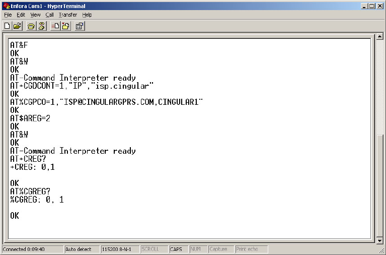
%CGREG: 0,1 (GPRS registered to home network)
Or
%CGREG: 0,5 (GPRS registered roaming.)
See Figure: 20 - "Verify GPRS Status"
Figure: 20 - Verify GPRS Status
Verify GPRS activation by sending the following command: AT$NETIP?<CR>
If the response is non-zero, then everything is working.
See Figure: 21 - "Verify GPRS Activation"
- 27 -
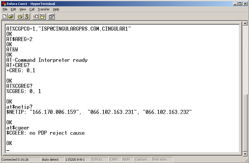
Figure: 21 - Verify GPRS Activation
If AT$NETIP returns all zeros, send the following command: AT$CGEER<CR>
There are three common responses:
l$CGEER: no PDP reject cause (Everything should be working OK)
l$CGEER: requested service option not subscribed (APN is incorrect or SIM has not been enabled for
data mode.)
l$CGEER: user authentication failed (username and/or password is incorrect.)
Configure the device to access the Enfora Server.
To configure the device for server interoperability, several things have to be addressed:
lMost GPRS configurations are Mobile Originate only. The mobile device must initiate a conversation
with a remote server before the remote server can talk to the device.
lIP addresses are dynamically assigned and can change.
lSome IP addresses are NAT and are non-routable IP addresses.
These issues are addressed with the following configuration commands.
The examples will use the following information:
- 28 -
lModem ID/name = “MT_Test”
lRemote Server DNS address = apitest.enfora.com
lRemote Server IP port = 1721
1. Give the device a unique name send the following command:
AT$MDMID=”MT_Test”
This command, combined with the wakeup message, will allow the server to associate a Public IP address
with a specific device and create a window of opportunity where the server can send commands to the
device See Figure: 4 - "Wakeup Command"
2. To talk with a specific server send the following command:
AT$FRIEND=1,1,”apitest.enfora.com”
3. To set the port number send the following command:
AT$UDPAPI=,1721
4. To Enable periodic messages (wakeup) to be sent to the server every 60 seconds send the following
command:
AT$WAKEUP=1,1
See Figure: 22 - "Wakeup Command"
- 29 -
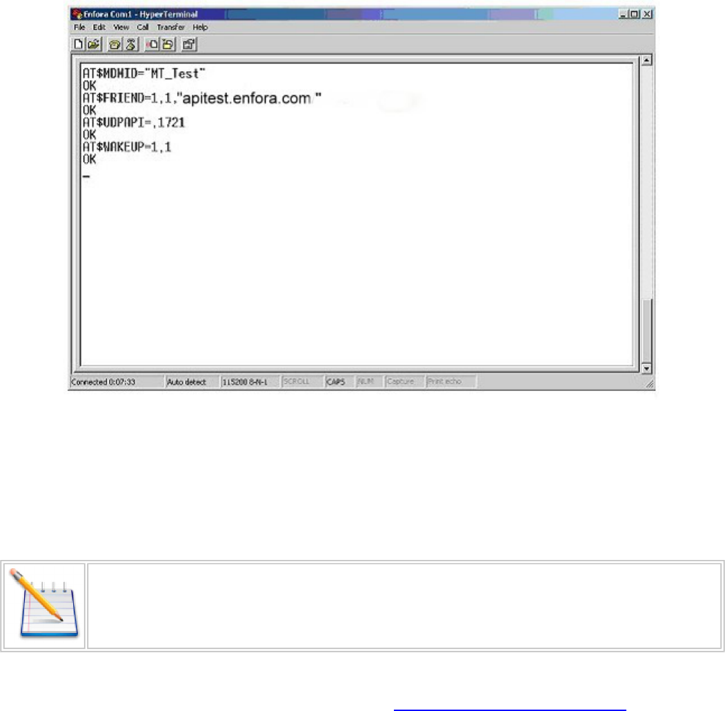
Figure: 22 - Wakeup Command
6.4 Verifying Server Connectivity
Note: For the following tests, Java Runtime must be installed on the computer. (To install
Java Runtime, please visit the Java website: http://www.java.com/en/download/manual.jsp)
1. Start Internet Explorer and enter the following URL: http://apitest.enfora.com/udpapp/
2. Enter the name used in the MDMID command in the box. Select Connect See Figure: 23 - "Verify
Server Connectivity"
- 30 -
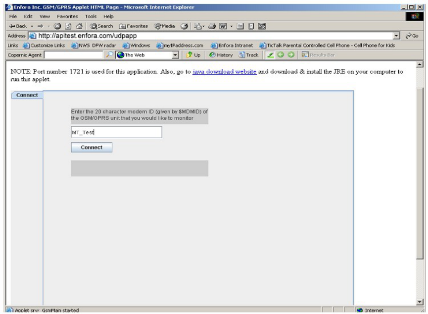

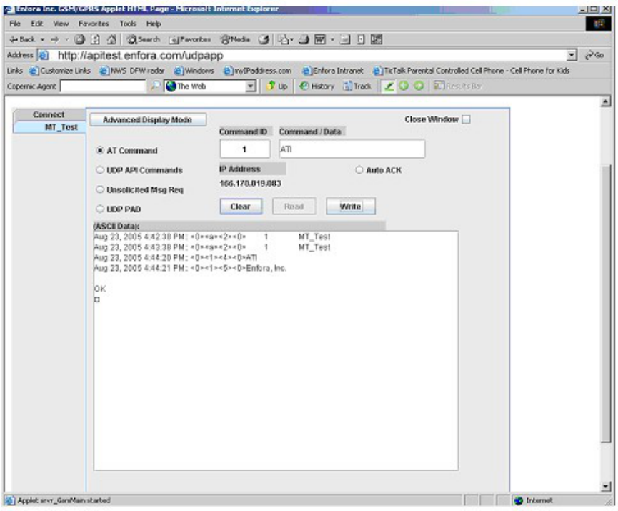
Figure: 25 - ATI Response
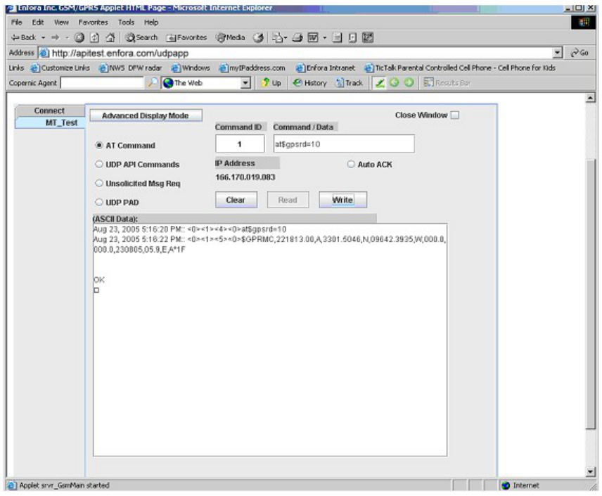
6.5 Verify GPS Operation
Follow these directions to verify GPS Operation.
1. From the terminal window, send the following command: AT$GPSRD=10<CR>
2. The device should respond with a standard GPRMC message that looks similar to the following:
$GPRMC,221223.00,A,3301.5080,N,09642.3857,W,000.0,000.0,230805,05.9,E,A*19
lA = OK
lV = Warning
l9 = Enfora Specific response that GPS solution is not valid and the last known GPS location is being
substituted.
- 33 -