Novatel Wireless GSM5218 GSM/GPRS Asset Tracker User Manual GSM2374UG001 MT 3000 User Guide
Novatel Wireless Inc. GSM/GPRS Asset Tracker GSM2374UG001 MT 3000 User Guide
User Guide

AT 3000 Series
User Guide
GSM5218UG001
Version:1.00
01 March, 2011
General
TERMS OF USE OF NEW MATERIALS - PLEASE READ CAREFULLY
From time to time, Enfora, in its sole discretion, may make available for download on its website
(www.enfora.com), or may transmit via mail or email, updates or upgrades to, or new releases of, the
firmware, software or documentation for its products (collectively, 'New Materials'). Use of such New
Materials is subject to the terms and conditions set forth below, and may be subject to additional terms
and conditions as set forth in Enfora's Technical Support Policy (posted on its website) and/or any written
agreement between the user and Enfora.
All New Materials are provided AS IS. Enfora makes no warranty or representation with respect to the
merchantability, suitability, functionality, accuracy or completeness of any such New Materials. The user of
such New Materials assumes all risk (known or unknown) of such use. Enfora reserves all rights in such
New Materials. The user shall have only a revocable and limited license to use such New Materials in
connection with the products for which they are intended. Distribution or modification of any New
Materials without Enfora's consent is strictly prohibited.
IN NO EVENT WILL ENFORA BE RESPONSIBLE FOR ANY INCIDENTAL, INDIRECT, CONSEQUENTIAL OR
SPECIAL DAMAGES AS A RESULT OF THE USE OF ANY NEW MATERIALS. ENFORA'S MAXIMUM LIABILITY
FOR ANY CLAIM BASED ON THE NEW MATERIALS SHALL NOT EXCEED FIFTY U.S. DOLLARS ($50).
Copyright
© 2011 Enfora, Inc. All rights reserved. Complying with all applicable copyright laws is the responsibility of
the user. Without limiting the rights under copyright, no part of this document may be reproduced, stored
in or introduced into a retrieval system, or transmitted in any form or by any means (electronic,
mechanical, photocopying, recording or otherwise), or for any purpose, without the express written
permission of Enfora, Inc.
Enfora and the Enfora logo are either registered trademarks or trademarks of Enfora, Inc. in the United
States.
251 Renner Pkwy
Richardson, TX 75080 USA
Phone: (972) 633-4400
Fax: (972) 633-4444
Email: info@enfora.com
www.enfora.com
- I -
Warranty Information
[Revised: 11/11/2010]
This warranty applies to (a) products sold directly by Enfora, unless a different warranty is specified in a
written agreement between Enfora and the purchaser; and (b) products sold to end users through a
distributor authorized by Enfora, but only where the authorized distributor does not provide a separate
warranty on such products, and Enfora has agreed to provide this warranty to such end users. If you
purchased the product from an authorized distributor, please check whether this warranty from Enfora, or
a separate warranty from the distributor, applies to your purchase. This warranty does not apply to any (i)
accessories or batteries for the products; or (ii) demonstration samples or prototypes of the products.
Unless otherwise provided in a written agreement between Enfora and the purchaser, all such accessories,
batteries, samples or prototypes are provided by Enfora AS IS without any warranty of any kind.
Enfora warrants to the original purchaser of the product from Enfora or its authorized distributor (as
applicable) that, for a period of one (1) year from the date of shipment of the product from Enfora, the
product hardware will be substantially free from defects in material or workmanship under normal
operation, and the product firmware will perform substantially in accordance with the product
documentation provided by Enfora. Enfora does not warrant that (a) the product hardware or firmware
will meet the purchaser's requirements; (b) the operation of the product hardware or firmware will be
uninterrupted or error-free; or (c) the product, when integrated in, or combined with, other products or
software not supplied by Enfora, will continue to perform substantially in accordance with the product
documentation. This limited warranty is for the benefit of the original purchaser, and is not transferable.
During the warranty period, Enfora, at its expense and in its sole discretion, will repair the product, or
replace the product with a corresponding or equivalent product, if it is determined to have a covered
defect, provided that the purchaser first notifies Enfora (directly or through its authorized distributor from
which the product was purchased) of any such defect, furnishes Enfora with a proof of purchase (if
required), requests and obtains a return merchandize authorization (RMA) number from Enfora, and
returns the product under that RMA to Enfora (or, at Enfora's option, to its authorized distributor), with the
shipping charges being prepaid by purchaser.If, upon reasonable examination of the returned product,
Enfora does not substantiate the defect claimed by purchaser, or determines that the defect is not covered
under this limited warranty, Enfora will not be required to repair or replace the product, but may instead
reship the product to the purchaser (or, at Enfora's option, to its authorized distributor where the product
can be made available to purchaser), in which case the purchaser shall be responsible for paying Enfora's
cost for reshipping the product to purchaser (or to Enfora's authorized distributor), and Enfora's usual
charges for unpacking, testing, and repacking the product for reshipment to purchaser (or to Enfora's
authorized distributor). Purchaser shall bear the risk of loss or damage in transit to any product returned
by purchaser to Enfora, or any returned product not found to be defective or covered under this warranty,
and reshipped by Enfora to purchaser (or to Enfora's authorized distributor). In the event Enfora repairs or
- II -
replaces a defective product covered by this limited warranty, the repaired or replacement product will be
covered under this limited warranty for the remainder of the original warranty period on the defective
product, or a period of ninety (90) days, whichever is longer. If Enfora is unable to repair or replace a
defective product covered by this limited warranty, Enfora will provide to purchaser a credit or a refund
(at Enfora's option) of the original purchase price (excluding taxes and shipping charges). Any returned and
replaced product, or any product for which Enfora has furnished a credit or a refund, becomes the
property of Enfora.
Enfora shall not have any obligation to provide any firmware bug fixes, upgrades or new releases except as
may be necessary to correct any covered defect of which purchaser notifies Enfora in writing during the
warranty period. Enfora, from time to time and in its sole discretion, may make available for download on
its website (www.enfora.com), or may provide via email, certain firmware bug fixes, upgrades or new
releases for the product. Download and use of any such bug fixes, upgrades or new releases is subject to all
of the applicable terms and conditions of Enfora's technical support policy as posted and updated on its
website. Enfora shall have no obligation under this limited warranty for (a) normal wear and tear; (b) the
cost of procurement of substitute products; or (c) any defect that is (i) discovered by purchaser during the
warranty period but for which purchaser does not request an RMA number from Enfora, as required
above, until after the end of the warranty period, (ii) caused by any accident, misuse, abuse, improper
installation, handling or testing, or unauthorized repair or modification of the product, (iii) caused by use of
any materials not supplied by Enfora, or by use of the product other than in accordance with its
documentation, or (iv) the result of electrostatic discharge, electrical surge, fire, flood or similar causes.
The purchaser (or its customers, as applicable) shall be solely responsible for the proper configuration,
testing and verification of the Enfora product prior to deployment in the field, and for ensuring that any
end user product or system into which the Enfora product is integrated or incorporated operates as
intended and meets the requirements of purchaser (or its customers). Enfora shall have no responsibility
whatsoever for the integration, configuration, testing, verification, installation, upgrade, support or
maintenance of any such end user product or system, or for any liabilities, damages, costs or expenses
associated therewith.
ENFORA'S SOLE RESPONSIBILITY AND PURCHASER'S SOLE REMEDY UNDER THIS LIMITED WARRANTY
SHALL BE FOR ENFORA TO REPAIR OR REPLACE THE PRODUCT (OR IF REPAIR OR REPLACEMENT IS NOT
POSSIBLE, PROVIDE A CREDIT OR REFUND OF THE PURCHASE PRICE) AS PROVIDED ABOVE. ENFORA
EXPRESSLY DISCLAIMS ALL OTHER WARRANTIES OF ANY KIND, EXPRESS OR IMPLIED, INCLUDING
WITHOUT LIMITATION ANY IMPLIED WARRANTIES OF NON- INFRINGEMENT, MERCHANTABILITY,
SATISFACTORY PERFORMANCE AND FITNESS FOR A PARTICULAR PURPOSE. IN NO EVENT SHALL ENFORA
BE LIABLE FOR ANY INDIRECT, SPECIAL, EXEMPLARY, INCIDENTAL OR CONSEQUENTIAL DAMAGES
(INCLUDING WITHOUT LIMITATION LOSS OR INTERRUPTION OF USE, DATA, REVENUES OR PROFITS)
RESULTING FROM A BREACH OF THIS WARRANTY OR BASED ON ANY OTHER LEGAL THEORY, EVEN IF
ENFORA HAS BEEN ADVISED OF THE POSSIBILITY OR LIKELIHOOD OF SUCH DAMAGES.
- III -
Some jurisdictions may require a longer warranty period than specified above and, accordingly, for
products sold in those jurisdictions the applicable warranty period shall be extended as required under the
laws of those jurisdictions. Furthermore, some jurisdictions may not allow the disclaimer of implied
warranties or the exclusion or limitation of incidental or consequential damages, so the above disclaimer,
limitation or exclusion may not apply to products sold in those jurisdictions. This limited warranty gives the
purchaser specific legal rights and the purchaser may have other legal rights that vary from jurisdiction to
jurisdiction. This limited warranty shall be governed by the laws of the State of Texas, United States of
America, without regard to conflict of laws principles. This limited warranty shall not be governed in any
respect by the United Nations Convention on Contracts for the International Sale of Goods.
Regulatory Compliance
FCC
This device complies with Part 15 of the FCC Rules. Operation is subject to the following two conditions: (1)
This device may not cause harmful interference, and (2) this device must accept any interference received,
including interference that may cause undesired operation.
This equipment has been tested and found to comply with the limits pursuant to Part 15 Subpart B, Part 22,
and Part 24 of the FCC rules. These limits are designed to provide reasonable protection against harmful
interference in an appropriate installation. This equipment generates, uses, and can radiate radio
frequency energy and, if not used in accordance with instructions, can cause harmful radiation to radio
communication. However, there is no guarantee that interference will not occur in a particular installation.
FCC RF EXPOSURE
Your Spider AT 3000 series device is a radio transmitter and receiver. It is designed and manufactured not
to exceed the emissions limits for exposure to radio frequency (RF) energy set by the Federal
Communications Commission (FCC) of the U.S. Government. These limits are part of comprehensive
guidelines and establish permitted levels of RF energy for the general population. These guidelines are
based on the safety standards previously set by the U.S. and international standards bodies. The standards
include a substantial safety margin designed to assure the safety of all persons, regardless of age and
health.
The exposure standard for wireless RF devices, such as the Spider AT 4000, employs a unit of measurement
known as the Specific Absorption Rate, or SAR. The SAR limit set by the FCC is 1.6W/kg. SAR values at or
below that limit are considered safe for the general public.
The Spider AT 3000 series conforms with the RF exposure requirements for portable devices in accordance
with FCC Part 2.1093.
- IV -
The Spider AT 3000 series transmitter is configured with a less than 10% transmission duty factor, for GPRS
Multislot class 8 operation, and is excluded from routine RF exposure evaluation in accordance with FCC
Mobile and Portable Device RF Exposure Procedures and Equipment Authorization Policies, KDB447498
D01, V04.
Canadian Compliance (Industry Canada)
IC ID: 4160A-GSM5218 MODEL NUMBER: GSM5218
This device complies with Industry Canada license-exempt RSS standard(s). Operation is subject to the
following two conditions: (1) this device may not cause interference, and (2) this device must accept any
interference, including interference that may cause undesired operation of the device.
The Spider AT 3000 series transmitter is configured with a less than 10% transmission duty factor, for GPRS
Multislot class 8 operation, and is excluded from routine RF exposure evaluation in accordance with the
requirements of RSS-102 section 2.5.
Le présent appareil est conforme aux CNR d'Industrie Canada applicables aux appareils radio exempts de
licence. L'exploitation est autorisée aux deux conditions suivantes : (1) l'appareil ne doit pas produire de
brouillage, et (2) l'utilisateur de l'appareil doit accepter tout brouillage radioélectrique subi, même si le
brouillage est susceptible d'en compromettre le fonctionnement.
L'émetteur de la série Spider AT 3000 est configuré avec un facteur de devoir de transmission de 10 %,
pour l'opération de classe 8 GPRS Multislot, au moins et est exclu de l'évaluation de l'exposition RF
conformément aux exigences de RSS-102 article 2.5 de la routine.
R&TTE Directive (CE)
The Spider AT 3000 series modem has been fully tested and complies with all applicable requirements of
EN301 489-1, EN301 489-7 and EN60950-1. Compliance to EN301 511 has been demonstrated by testing on
both the GSM5218 and the integrated LPP0208 module
ROHS COMPLIANCE
The Spider AT 3000 series complies with the European Union Restriction of the Use of Certain Hazardous
Substances in Electrical and Electronic Equipment (RoHS) Directive (2002/95/EC), effective since July 1,
2006.
DISCLAIMER
The information and instructions contained within this publication comply with all applicable FCC, GCF,
PTCRB, R&TTE, IMEI and other applicable codes that are in effect at the time of publication. Enfora
disclaims all responsibility for any act or omissions, or for breach of law, code or regulation, including local
or state codes, performed by a third party. Enfora strongly recommends that all installations, hookups,
- V -
transmissions, etc., be performed by persons who are experienced in the fields of radio frequency
technologies. Enfora acknowledges that the installation, setup and transmission guidelines contained within
this publication are guidelines, and that each installation may have variables outside of the guidelines
contained herein. Said variables must be taken into consideration when installing or using the product, and
Enfora shall not be responsible for installations or transmissions that fall outside of the parameters set
forth in this publication.
- VI -

Table of Contents
1 Introduction 1
1.1 Reference Documents 2
2 Physical Description 3
2.1 Overview 3
2.1 Controls and Indicators 5
2.1 Dimensions 6
2.1 Environmental Specification 8
2.2 Temperature 8
Spider AT 3000 and Spider AT3001 8
Spider AT 3010 and Spider AT3011 8
2.1 Water Resistance 9
2.1 Radio Performance Specifications 10
2.1 GSM/GPRS Compliance Specifications 11
2.1 Battery Specifications 12
2.1 Intrinsic Safety Specification 13
2.1 GPS Functionality 14
3 Initial Setup 15
3.1 Configure the Device 17
3.1 Configure the Spider AT 3000 series Manually using the Device Configuration Utility 18
3.1 Provision the Spider AT 3000 Series Using the Provisioner 19
4 Mounting the Unit 20
4.1 Hardware Needed To Mount the Device 21
4.1 Selection of Mounting Locations 22
4.1 Pre-Drilling of Mounting Holes 23
4.1 Mounting the Device 24
4.1 Alternate Mounting of the Device 25
- VII -

4.1 Mounting Bracket 26
4.1 Attaching the Bracket Using Tape 27
4.1 Attaching the Bracket Using Screws 28
5 Replacing the Battery 29
5.1 Disconnect the Battery 30
5.1 Connect the Battery 31
6 Powering Up and Down 32
7 Device Operation 33
7.1 Power Management 33
7.1 Position Reporting 34
7.1 Report Exceptions 35
7.1 Over the Air Configuration 36
7 Software Upgrade 37
7.1 Over the Air Upgrade 37
7.1 USB Upgrade 38
8 USB Driver Installation 39
8.1 Connect the Spider AT 3000 to a USB Port 39
8.2 Install the USBDrivers 39
9 SIM Card Installation 56
9.1 SIMCard Holder 56
9.2 SIM Card Installation 56
- VIII -

Table of Figures
Figure: 1 - Spider AT 3010 Circuit Board and Battery Pack 3
Figure: 2 - Top View of Spider AT3000 Series 4
Figure: 3 - Bottom View of Spider AT 3000 Series 4
Figure: 4 - Spider AT 3000 Dimensions 7
Figure: 5 - Internal View of Spider AT 3010 with Circuit Board and Battery Pack 15
Figure: 6 - Spider AT 3000 and Mounting Hardware 21
Figure: 7 - Spider AT 3000 Screw Hole 23
Figure: 8 - Spider AT 3000 and Mounting Hardware 24
Figure: 9 - Mounting – Cable Ties 25
Figure: 10 - Mounting Bracket BRK5002 – Bottom 26
Figure: 11 - Mounting Bracket BRK5002 – Top 26
Figure: 12 - Open Unit 30
Figure: 13 - Insert New Battery 31
Figure: 14 - LED Indicator and Power Switch 32
Figure: 15 - Found New Hardware Wizard Window 40
Figure: 16 - Hardware Wizard – Install from specific location 41
Figure: 17 - Hardware Wizard – Search for best driver 42
Figure: 18 - Hardware Wizard – Install Progress 43
Figure: 19 - Hardware Wizard – Completing 44
Figure: 20 - Hardware Wizard – Install from specific location 45
Figure: 21 - Hardware Wizard – Install from List 46
Figure: 22 - Hardware Wizard – Search for best driver 47
Figure: 23 - Hardware Wizard – Windows Logo testing 48
Figure: 24 - Hardware Wizard – Installation Progress 49
Figure: 25 - Hardware Wizard – Installation Complete 50
Figure: 26 - Hardware Wizard – New Hardware 51
- 9 -


1 Introduction
An extension to the Enfora Spider® family of integrated asset management solutions, the Spider AT 3000
series are certified quad-band integrated platform that provides GSM/GPRS/GPS functionality for mobile
asset monitoring. The Spider AT 3000 for long life reporting, Spider AT 3001 for long life reporting in
Intrinsic Safety environments, Spider AT 3010 for more frequent reporting, and Spider AT 3011 for more
frequent reporting in Intrinsic Safety environments.
The Spider AT 3000 series has the following features:
lFully Integrated - no need for external antenna or power source
lWireless Connection Reliability
lSuperior GPS Sensitivity & Geofencing
lSimplified Over the Air Configuration & Provisioning
The Spider AT 3000 series are based on Enfora’s innovative Enabler III Low Power Platform, with a built-in
programmable software environment.
Designed for the intelligent monitoring of non-powered mobile and fixed assets the Spider AT 3000 is
easily installed and managed.
The Spider AT 3000 series can be provisioned through the Enfora CMS and configured to optimize:
lMotion detection
lLocation monitoring
lReporting geofence settings
- 1 -

1.1 Reference Documents
The following Enfora documents may be necessary to configure the Spider AT 3000 series:
lCMS User Guide
lProvisioner User Guide
lProvisioner Quick Start Guide
lDevice Configuration Utility User Guide
The following instructions and information relate to all Spider AT 3000 series
products, however for clarity, only the Spider AT 3000 product will be referenced.
- 2 -
2 Physical Description
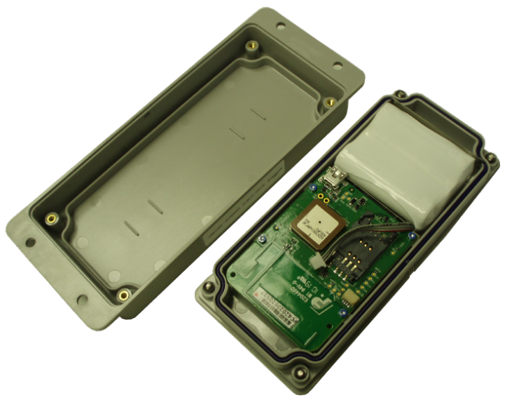
2.1 Overview
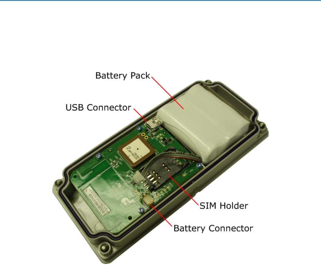
The Spider AT 3000 series is a quad-band integrated platform. Inside the gray plastic case is an Enfora
Enabler LPP0208 modem, USB connector, SIM holder and battery connector for the attached battery. See
2.1 "Overview" .
Figure: 1 - Spider AT 3010 Circuit Board and Battery Pack
- 3 -
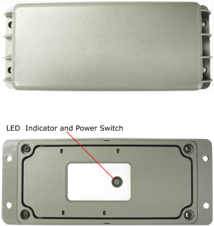
Figure: 2 - Top View of Spider AT3000 Series
Figure: 3 - Bottom View of Spider AT 3000 Series
- 4 -
2.1 Controls and Indicators
The button on the underside of the Spider AT 3000 functions as both the power switch and the activation
switch.
To deactivate the Spider AT 3000, press and hold the power switch, located on the underside of the unit,
for three to five seconds. The LED will become solid red then go off. When the light is off, the unit is
deactivated.
When you are ready to activate the Spider AT 3000, press and hold the power switch for three to five
seconds until you see a blinking light. The LED will blink 12 times within a 3 second period if the battery
voltage is in its highest range. If the battery is within its normal voltage range, the LED will blink on for one
second, off for one second, then on for one second. The LED will then go off. When the light is off, the unit
is activated.
- 5 -
2.1 Dimensions
The measurements of the Spider AT 3000 and 3001 are:
lLength 170 mm
lWidth 69 mm
lHeight 21 mmSee "Dimensions" on page 6
lWeight (with battery) 207 grams
lWeight (without battery) 150 grams
The measurements of the Spider AT 3010 and 3011 are:
lLength 170 mm
lWidth 69 mm
lHeight 21 mm
lWeight (with battery) 198 grams
lWeight (without battery) 150 grams
- 6 -
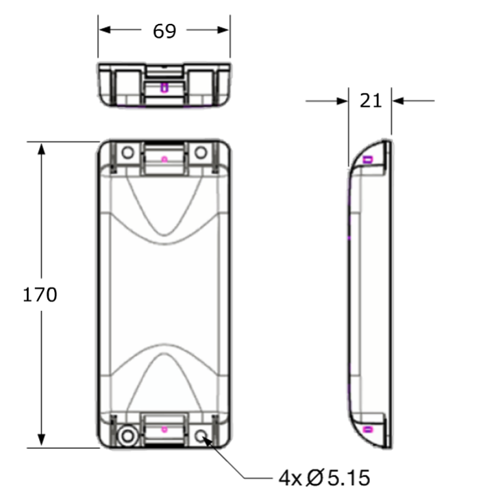
Figure: 4 - Spider AT 3000 Dimensions
- 7 -
2.1 Environmental Specification
2.2 Temperature
Spider AT 3000 and Spider AT3001
Compliant -20°C to 60°C
Operating -30°C to 85°C
Storage -40°C to 85°C
Spider AT 3010 and Spider AT3011
Compliant -20°C to 60°C
Operating -40°C to 60°C
Storage -40°C to 70°C
- 8 -
2.1 Water Resistance
The Spider AT 3000 series is an ingress resistant device, pursuant to the IP-66 and IP-68 ratings. This rating
specifies that the device is fully protected against dust, and can be immersed in water.
- 9 -

2.1 Radio Performance Specifications
Frequency 850 / 900 / 1800 / 1900 MHz
Sensitivity 108 dBm (typical)
Transmit Power Class 4 (2W @ 850 / 900 MHz)
Class 1 (1W @ 1800 / 1900 MHz)
Table: 1 - Radio Performance Specifications
- 10 -

2.1 GSM/GPRS Compliance Specifications
The following list shows the certifications for the Spider AT 3000.
FCC Parts 15, 22 & 24
GCF Version 3.37.1
PTCRB Version 5.3
CE Mark Yes
Industry Canada Yes
RoHS Compliant Yes
Table: 2 - GSM GPRS Compliance Specifications
- 11 -

2.1 Battery Specifications
Spider AT 3000
The Spider AT 3000 uses a battery pack. The features of this battery include:
lGreater energy density
lHigher capacity
lHigher temperature range
lHigher operating voltage
lLonger life
lPatented safety features
lEnvironmentally friendly
Battery Pack Characteristics
Enfora PN BAT-5208-02
Chemistry Lithium-Thionyl Chloride (LI-SOCl2)
Shelf Life 10 years @ <30 °C
Lithium Metal Content Approx. 1.3 g
Weight 60 g (max)
Spider AT 3010
The Spider AT3010 uses a battery pack. The features of this battery include:
lGreater energy density
lHigher capacity
lExtended lower temperature range
lAllows for more rapid device reporting capability
lHigher operating voltage
lLong life
lPatented safety features
lEnvironmentally friendly
Battery Pack Characteristics
Enfora PN BAT-5208-01
Chemistry Lithium Iron Sulfide (LiFeS2)
Shelf Life 10 years @ <30 °C
Lithium Metal Content <1.0 gram per cell
Weight 50 g (max)
- 12 -

2.1 Intrinsic Safety Specification
Intrinsic safety is important in environments where flammable substances (gases or solid particles) may
exist. Two variants of the Spider AT 3000 series product line are certified for use in Intrinsically Safe
environments. These products include unique labels which identify to the interested parties what
certifications are in place.
The Spider AT 3001 has been designed and tested to meet the following Intrinsic Safety Certifications: EU
Directive 94/9/EC, according to the standards EN 60079-0: 2006 and EN 60079-15: 2005, the product has
been certified for Zone 2, Category 3.
The Spider AT 3011 has been designed and tested to meet the following Intrinsic Safety Certifications: Class
I Division 1, groups C and D according to the requirements of UL913 and CSA 22.2, for use in the United
States of America and in Canada. The product is specifically marked with Exia along with other wording to
indicate to the user that this is an intrinsically safe certified device.
Warning: Do not remove or modify the labels on the Spider AT 3001 or Spider AT
3011, doing so will invalidate the intrinsic safety certification.
- 13 -

2.1 GPS Functionality
Channels: 16
Sensitivity:
Monitoring: -158 dBm (typical)
Reacquisition: -157 dBm (typical)
Cold Start: -147 dBm (typical)
Position Accuracy (horizontal)
-130 dBm, Autonomous CEP (50%): <2m (typical)
-150 dBm, Autonomous CEP (50%): <2m (typical)
-130 dBm, Autonomous CEP (50%): <5m (typical)
-150 dBm, Autonomous CEP (50%): <5m (typical)
Table: 3 - GPS Functionality
- 14 -
3 Initial Setup
Please follow these steps to start using the Spider AT 3000 series:
1. Make sure you have the following items:
lSpider AT 3000 series device.
lUSB Drivers.
lUSB cable (USB-A to 5-Pin Mini USB)
2. Remove the Spider AT 3000 from the packaging material.
3. The Spider AT 3000 will be assembled loosely with four screws. Fully loosen the screws and separate
the two halves of the unit.
4. Make sure the battery is connected (See "Connect the Battery" on page 31).
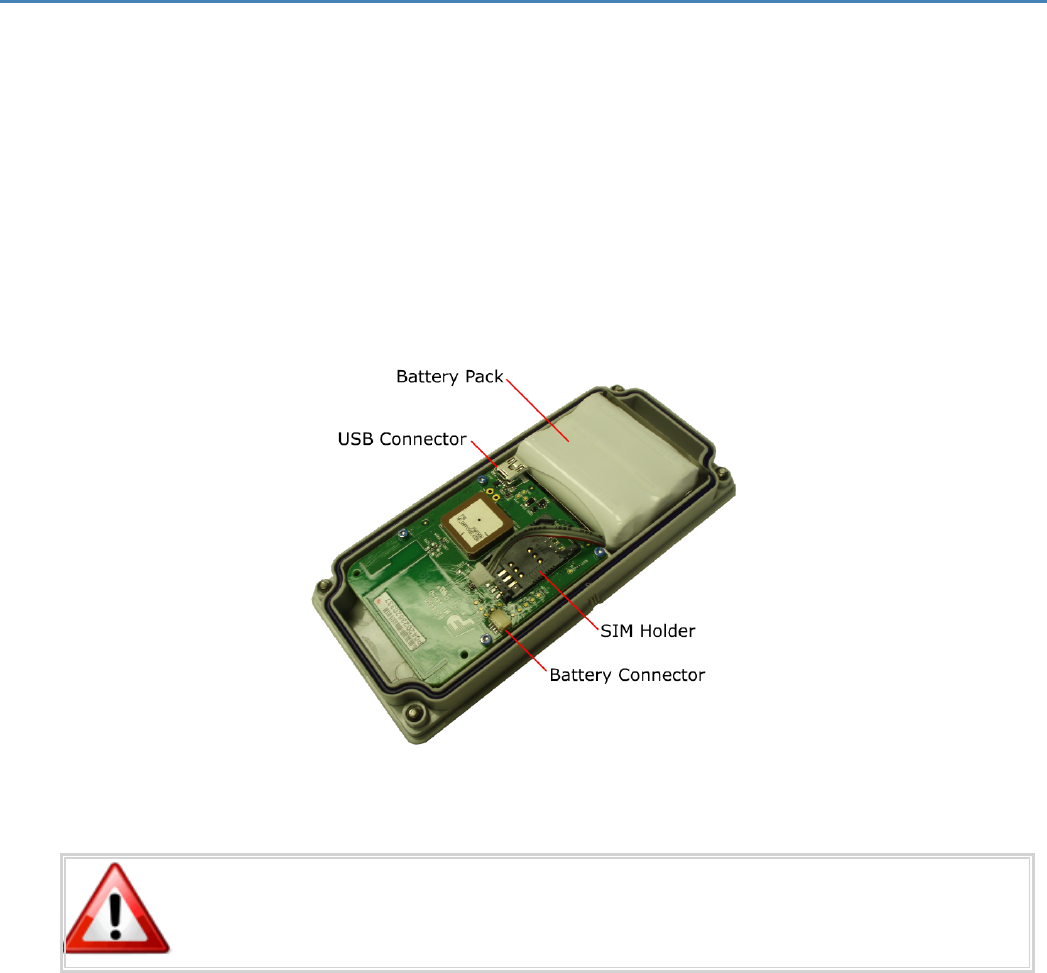
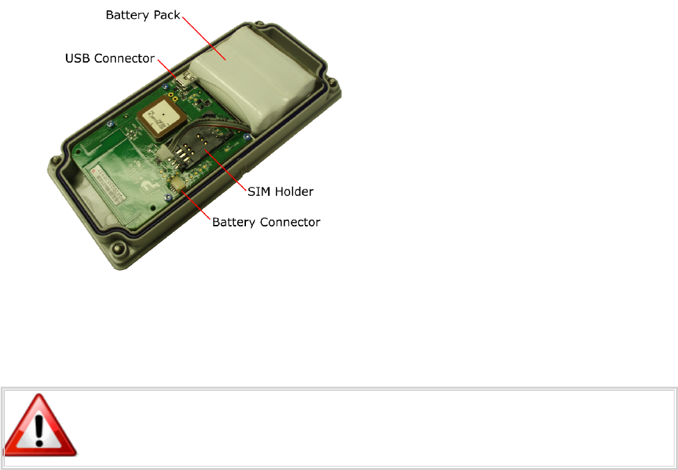
Figure: 5 - Internal View of Spider AT 3010 with Circuit Board and Battery Pack
To Reduce the risk of ignition of a flammable or explosive atmosphere; batteries
must be inserted or changed only in a location known to be non-hazardous.
- 15 -

5. Remove the battery pack from the half of the Spider AT 3000 that contains the circuit board. You
don’t need to disconnect the battery connector – just move the battery pack out of the way, so you
can access the USB connector.
6. Remove the battery pack from the half of the Spider AT 3000 that contains the circuit board. You
don’t need to disconnect the battery connector – just move the battery pack out of the way, so you
can access the USB connector.
7. Install the SIM (See "SIM Card Installation" on page 56).
8. Turn the device on (See "Powering Up and Down" on page 32).
9. Connect the USB cable to the circuit board and to your computer.
10. Install the drivers (See "USB Driver Installation" on page 39).
11. Configure the Spider AT 3000 (See "Configure the Device" on page 17).
12. Once configuration is complete, remove the USB connector, and replace the battery pack.
13. Close the Spider AT 3000, and replace the screws.
14. The Spider AT 3000 is now activated, and will begin transmitting data.
Verify the Server is receiving messages from the device.
If you are ready to deploy the Spider AT 3000, mount the unit on the asset you need
to locate (See "Mounting the Unit" on page 20). If you are not ready to deploy,
deactivate the unit until you are ready (See "Powering Up and Down" on page 32).
- 16 -

3.1 Configure the Device
Once the USB drivers are installed, and you can communicate with the Spider AT 3000, you can begin
configuring the unit to transmit data.
Before using the Enfora Provisioner to configure the device over-the-air, basic
communication parameters must be configured using a terminal program and USB
connection.
The only supported method of configuring the Spider AT 3000 with the basic parameters is to use the
Device Configuration Utility. The Spider AT 3000 requires Device Configuration Utility version 1.0.3 or
later.
- 17 -

3.1 Configure the Spider AT 3000 series Manually using
the Device Configuration Utility
Installation of the Device Configuration Utility and configuration of the device using this tool are detailed in
the Device Configuration Utility User Guide.
Once the initial configuration has been performed with the Device Configuration Utility you will be able to
communicate with the server that is hosting the Provisioner software, and configure the Spider AT 3000
over-the-air. Refer to the Provisioner User’s Guide for detailed device configuration instructions.
The default Spider AT 3000 parameters result in the device reporting to the server
when activated and then once per day. When not actively reporting to the server, the
device will be in sleep mode and will not receive commands from the Provisioner
server until it wakes up for its daily report.
- 18 -
3.1 Provision the Spider AT 3000 Series Using the
Provisioner
Once the device has been configured it will be ready to be provisioned by the Provisioner. To provision the
Spider AT 3000 over-the-air, refer to the Provisioner User’s Guide for detailed device configuration
instructions.
- 19 -

4 Mounting the Unit
The unit can be mounted to a variety of surfaces including wood, metal and plastic. Any of the following
mounting hardware (not included) can be used:
lFour #8 washers, four #8 Self-Drilling Sheet Metal Screws.
lCable Ties.
lDouble-sided Pressure Sensitive Adhesive (PSA) Tape
The optimal mounting position of the Spider AT 3000 is outdoors, ensuring that the top of the device has
clear access to the sky.
It is recommended that the user conducts testing in various situations, in order to
determine if the unit will:
• Transmit data.
• Acquire a GPS lock
This procedure describes the mounting of the Spider AT. Please read this entire procedure and ensure that
all equipment is available and personnel are trained before starting the work.
- 20 -
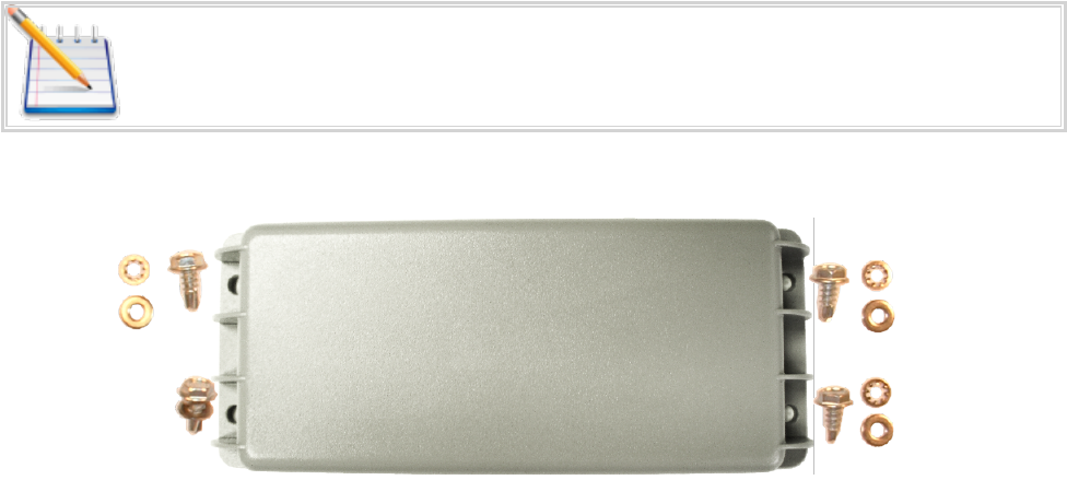
4.1 Hardware Needed To Mount the Device
The following is a list of mounting hardware that may be used with the Spider AT 3000. ( See 4.1
"Hardware Needed To Mount the Device" )
lAppropriate Mounting Screws- Qty 4.
lAppropriate Lock-Washers- Qty 4.
lAppropriate Flat-Washers- Qty 4.
lUser defined hardware may also be used to mount the Device.
Mounting hardware is not included with the device.
Figure: 6 - Spider AT 3000 and Mounting Hardware
- 21 -
4.1 Selection of Mounting Locations
Care should be taken in selecting the mounting location for the Spider AT 3000. Some considerations for
choosing the mounting location are:
lIdeally the label should be mounted facing down (Towards the ground) such that the top of the unit
has a clear view of the sky. Mounting in this orientation provides optimum antenna performance.
lIf the above mounting is not possible the unit may be mounted on its side where the label is mounted
against the asset and the top of the unit faces towards the sky as much as possible.
lThe selected mounting surface must not allow water to pool around the device.
lCare should be taken to avoid damaging wiring, electronics, plumbing, etc, when drilling holes to
mount the device.
lThe device should be mounted where it is protected from being impacted during operation.
- 22 -
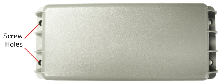
4.1 Pre-Drilling of Mounting Holes
After selecting the proper location for the device, hold the device in position. Use the four screw-hole
openings to mark the center points for pre-drilling. Place the device aside and pre-drill with the
appropriate drill bit.
Figure: 7 - Spider AT 3000 Screw Hole
- 23 -
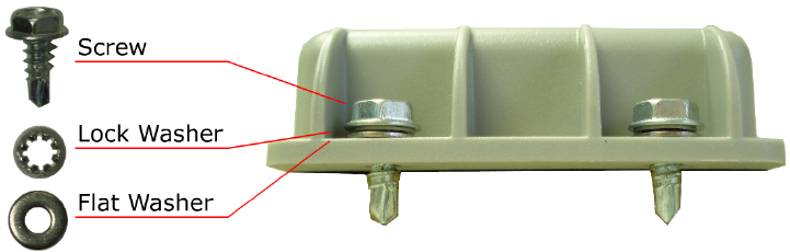
4.1 Mounting the Device
Place a Lock-Washer on one of the Screws. Now place a Flat-Washer on the Screw, See "Mounting the
Device". Repeat this process with the remaining three Screws.
Figure: 8 - Spider AT 3000 and Mounting Hardware
Insure the Device is activated (See "Powering Up and Down" on page 32). Align the Device with the pre-
drilled screw holes. Insert one of the screws (assembled above) through one of the screw holes in the
Device. Partially tighten the Screw into the mounting surface. Repeat this process until all four screws are
started into the mounting surface. Now tighten the four screws until they are snug. Tighten the Screws to
2.5 in-lb torque.
- 24 -
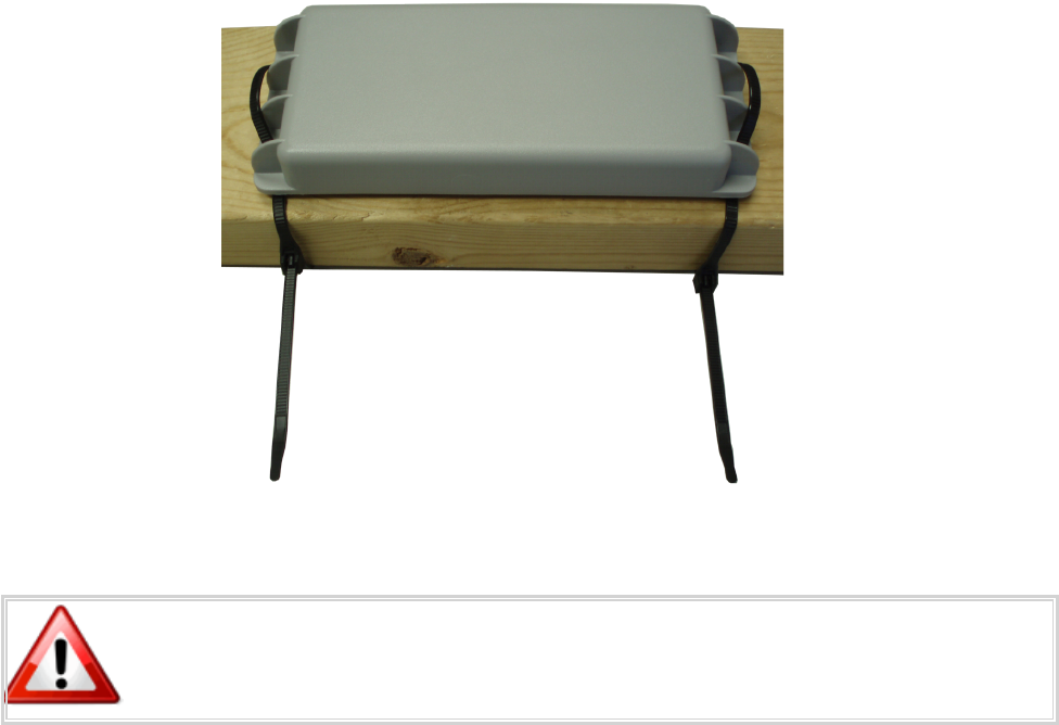
4.1 Alternate Mounting of the Device
The Device can also be mounted using Cable Ties. The screw holes are sized so the Cable Ties can be
inserted through them, See 4.1 "Alternate Mounting of the Device" .
Figure: 9 - Mounting – Cable Ties
Take care not to fasten Cable Ties over sharp edges, as this may cause excessive
wear causing the Cable Ties to break.
- 25 -
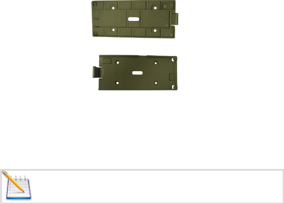
4.1 Mounting Bracket
The BRK5002 bracket was designed to survive rigorous use and the most extreme outdoor environments.
Figure: 10 - Mounting Bracket BRK5002 – Bottom
Figure: 11 - Mounting Bracket BRK5002 – Top
The BRK5002 bracket has passed vibration testing of 24 hrs at 20g (from 50 to 2000 Hertz). In addition, the
release clasp has been tested to hundreds of cycles including temperature shock with near freezing liquid
immersion.
Both the Spider AT 3000 series housing and BRK5002 bracket have been produced with UV stabilized
plastic. UV Stabilization prevents plastics from oxidizing and becoming brittle over time due to exposure to
the sun.
Note: For optimum performance mount the device on a vertical or inclined surface
- 26 -

4.1 Attaching the Bracket Using Tape
Preparation
1. Clean the surface of the bracket and the mounting surface well.
A typical surface cleaning solvent is IPA/water mixture (rubbing alcohol)
2. Remove all grease, dirt and oxide particles from the bonding surface.
3. Wipe the surface dry.
4. Refer to the 3M documentation to obtain more detailed guidance:
http://training.enfora.com/docs/3MVHBTape.html
Pressure sensitive adhesives use viscous flow to achieve substrate contact area.
The ideal tape application temperature range is 70°F to 100°F (21°C to 38°C).
The minimum suggested application temperature is 50°F (10°C)
Note: Initial tape application to surfaces at temperatures below the suggested
minimum is not recommended because the adhesive becomes too firm to adhere
readily. However, once properly applied, low temperature holding is generally
satisfactory. To obtain good performance with all 3M™ VHB™ Tapes, it is important
to ensure that the surfaces are dry and free of condensed moisture.
Attachment
1. Insert the device into the bracket.
2. Apply the tape provided to the surface of the bracket, as shown.
3. Remove the tape covering and attach the bracket to the surface.
4. Apply firm pressure (Greater than 15 psi is recommended)
5. It is recommended to wait at least 20 Minutes for the adhesive to bond.
- 27 -

4.1 Attaching the Bracket Using Screws
Preparation
1. Mark the location of the 4 self-tapping screws on the mounting surface.
2. For heavy gauge metals use the table below:
Pilot Hole Diameter for Self Tapping Screws
Sheet Thickness (mm) Sheet Material
From To Steel Aluminum
0.89 1.38 3.2 3.3
1.3 3 3.3 3.4
3.01 3.5 3.4 3.5
3.51 10 3.5 – 3.6 3.6 - 3.7
Table: 4 - Pilot Hole Diameter for Self Tapping Screws
Attachment
1. Screw the bracket in place using the 4 provided self-tapping screws.
2. Firmly tighten the screws.
3. Mount the device in the bracket.
- 28 -

5 Replacing the Battery
When the device requires the battery to be changed use the following instructions:
Warning: To Reduce the risk of ignition of a flammable or explosive atmosphere;
batteries must be inserted or changed only in a location known to be non-hazardous.
- 29 -
5.1 Disconnect the Battery
1. Remove the Spider AT 3000 from its mounted location.
2. Fully loosen the four screws, so the two halves of the unit are separated.
Figure: 12 - Open Unit
3. Disconnect the old battery by grasping the battery cable close to the connector and gently pull side-
ways
4. Remove the battery from the case.
- 30 -
5.1 Connect the Battery
1. Insert the Battery into the Bottom Housing Assembly with the cable up and to the right, See 5.1
"Connect the Battery"
See "Connect the Battery" on page 31
Figure: 13 - Insert New Battery
2. Connect the new battery by attaching the connector to the battery terminals.
3. Close the Spider AT 3000 and replace the screws.
Take care to Tighten the Screws to 2.5 in-lb torque.
4. Remount the device in its original location.
- 31 -
6 Powering Up and Down
The button on the underside of the Spider AT 3000 functions as both the power switch and the activation
switch.
After the provisioning process is complete, the Spider AT 3000 will be activated. If you do not plan to
deploy the unit immediately, you should deactivate the Asset Tag, so as not to drain the battery.
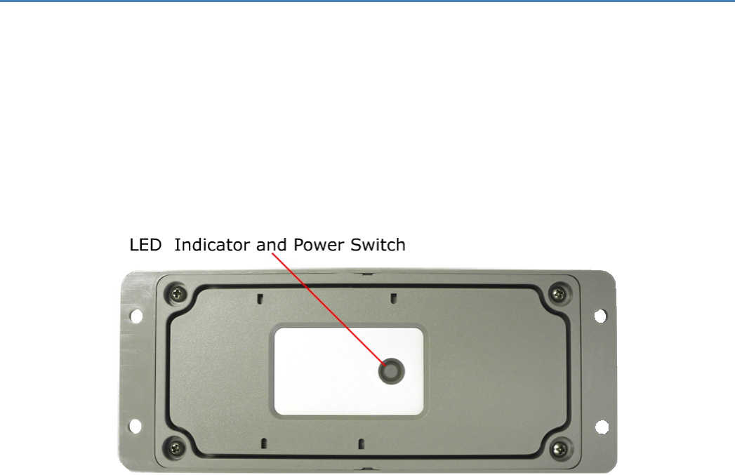
To deactivate the Spider AT 3000, press and hold the power switch, located on the underside of the unit,
for three to five seconds. The LED will become solid red then go off. When the light is off, the unit is
deactivated.
Figure: 14 - LED Indicator and Power Switch
When you are ready to activate the Spider AT 3000, press and hold the power switch for three to five
seconds until you see a blinking light. The LED will then go off. When the light is off, the unit is activated.
- 32 -

7 Device Operation
7.1 Power Management
The Spider AT 3000 has been designed to minimize power consumption to maximize battery life. The
device has different power states to optimize system-level power consumption. The Spider AT 3000 uses a
low-power microcontroller to control the power states. Between position reports, the microcontroller
enters an idle state until the next scheduled position check. When it is time to check for a new position, the
microcontroller can use the motion sensor and GPS receiver to determine if the device has moved. If the
device has not moved, the microcontroller can quickly return to the idle state without generating a position
report.
The power states are:
lMicrocontroller idle – This is the lowest power state. The microcontroller is powered on but the proc-
essor is idle waiting for a timer expiry based upon the next scheduled position check.
lMotion sensor – The motion sensor is used as an ultra-low power detection of movement. This state
only lasts a few seconds while the motion sensor is measured to detect movement. If no motion is
detected, then the device may return to the idle state. If motion is detected, then the GPS receiver is
turned on.
lGPS receiver – The microcontroller and GPS receiver are powered. The GPS receiver acquires the
GPS satellites and determines the current position. A geofence may be used to determine if the new
position is a significant (configurable) distance from the previous position.. If the device is still
located with the geofence boundary, then the device may return to the idle state.
lGSM modem – The GSM modem is turned on only if a position report is needed. The modem reg-
isters on the GSM network and sends the position report to the remote server. After transmitting the
position report, the modem remains registered on the GSM network for a period of time and listens
for new over-the-air configuration messages from the server.
External power does not guarantee that the device will be in "tracking" mode where
the modem and GPS receiver are always powered on. Now, the device will be in
tracking mode if the next report is scheduled in <5 minutes based upon the CFGIP and
CFGOP parameters.
- 33 -
7.1 Position Reporting
The Spider AT 3000 transmits two types of position data. If the GPS receiver is able to determine a valid
GPS position, then the GPS position information is transmitted. If the Spider AT 3000 is unable to acquire a
valid GPS position, then PCELL information is transmitted. This PCELL information describes the GSM
cellular network environment viewed by the Spider AT 3000 and can be used to determine an approximate
location.
The Spider AT 3000 will send a position report to the server immediately after being activated (See
"Powering Up and Down" on page 32). After activation, the Spider AT 3000 can be configured to
periodically report its position based upon several usage scenarios. These usage scenarios include:
lStatic Asset Monitoring with time interval reporting
lStatic Asset Monitoring with time-of-day reporting
lBasic Motion Monitoring
lMobile Asset Monitoring with pre-defined geofence(s)
lMobile Asset Monitoring with dynamic geofence
Refer to the Provisioner User’s Guide for detailed device configuration instructions.
- 34 -
7.1 Report Exceptions
Several conditions may prevent the position report from being sent at the expected time. These conditions
include:
lDelayed position reports – Several environmental factors may cause a position report to be delayed
temporarily. If a position report is delayed, then a new position report will be calculated and trans-
mitted when the environmental factor has been cleared.
oExtreme temperature – If the temperature is outside of the recommended operating range of
the Spider AT, then the GPS receiver and GSM modem will not be powered on. The report will
be delayed until the temperature is within the product’s acceptable temperature range.
oMarginal temperature - If the temperature is marginal, then there is a minimum time interval
required between reports to insure that the battery is sufficiently recharged to successfully
transmit the position report. If a position report is scheduled before this minimum time inter-
val has expired, then the report will be delayed until the minimum time interval has expired.
oLow voltage – If the battery voltage is too low, then the position report will be delayed until
the battery voltage is above the product’s minimum battery threshold. This delay provides an
opportunity for the battery to recharge.
lNo GSM coverage – If the Spider AT 3000 cannot register on the GSM network or cannot transmit
the position report, then the report is stored in internal memory. The stored message will be sent at
the next opportunity when the GSM modem is powered on to transmit the next scheduled position
report. A maximum of 10 messages will be stored.
lTime of day reporting without RTC – The Spider AT 3000 uses valid GPS data to automatically set the
RTC time. If the Spider AT 3000 has not detected valid GPS data since the last activation, then the
RTC time will not be accurate. If the Spider AT 3000 is configured to use the Static Asset Monitoring
with Time-of-Day Reporting service and the RTC time is not accurate, then the Spider AT 3000 will
still report at the desired time intervals, but it will report at a random day/time. For example, it will
report each day but not at the desired time of day.
lDelta time reporting drift – The time between position reports (unless using Time-of-Day) is a delta
time interval since the last report. This time interval does not include the time to gather the position
data and register on the GSM network. The GPS receiver acquisition and GSM registration times vary
and will cause the time between reports to be several minutes longer than the specified reporting
time interval. For example, if the Spider AT 3000 is configured to report once per day and the device
is activated at 12:00 PM on Monday, then the next several reports will occur approximately at 12:05
PM Tuesday and then 12:10 PM on Wednesday.
lUDP packet lost in network – The Spider AT 3000 uses the UDP data transport protocol. Although the
vast majority of position reports will be delivered successfully to the server, a small number of posi-
tion reports may be dropped in transit by the GSM or internet network.
- 35 -
7.1 Over the Air Configuration
After transmitting a position report to the server, the Spider AT 3000 remains registered on the GSM
network for a period of time and listens for new over-the-air configuration messages from the server.
Using the Provisioner, the position reporting time or usage scenario may be modified. The Spider AT 3000
can only receive new configuration commands when registered on the GSM network.
- 36 -

7 Software Upgrade
7.1 Over the Air Upgrade
The Spider AT 3000 software may also be upgraded using the GSM network to program the device
remotely over-the-air. Refer to the Provision User Guide for details of the FOTA service.
- 37 -
8 USB Driver Installation
The first time the user provisions the Spider AT 3000, it must be via the USB connection. After the first
time, it can be configured over-the-air. Follow these steps to begin provisioning the device. These
instructions illustrate how to correctly install the USB drivers in Windows XP. The procedure will vary for
other Operating Systems.
1. Connect the Spider AT 3000 to the USB port on a Windows-based computer.
2. Install the USB drivers (as described in this Appendix).
8.1 Connect the Spider AT 3000 to a USB Port
Supported Operating Systems include Windows 2000, Windows XP, and Windows Vista. When you connect
the Spider AT 3000 to the computer, you will be prompted to install the drivers.
Note: In order to access the USB port on the Spider AT 3000, you will need to remove
the cover. The USB connector is located on the circuit board inside the unit.
Follow the steps in the next section to install the drivers.
8.2 Install the USBDrivers
After you download the USB drivers, make sure you note the location on your computer where the drivers
are located.
Note: Drivers can be downloaded from the Enfora® Website.
After connecting the Spider AT 3000 to the computer, follow these steps to complete the installation of the
USB drivers:
- 39 -

There are three steps to installing the USB drivers. The first will install the Locosto drivers. Once this
installation is complete, the process will automatically begin again. The second step will install the
Enabler®III LPP Trace. The third step will install the Enabler®III LPP Modem.
1. The Windows Operating System will detect the new USB device.
2. You will see the following screen:
Figure: 15 - Found New Hardware Wizard Window
3. Click on No, not this time.
4. Click Next.
5. You will see the following screen:
- 40 -
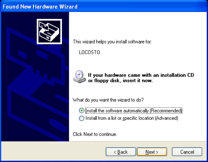
Figure: 16 - Hardware Wizard – Install from specific location
6. Click the radio button next to Install from a list or specific location (Advanced).
7. Click Next.
8. You will see the following screen:
- 41 -
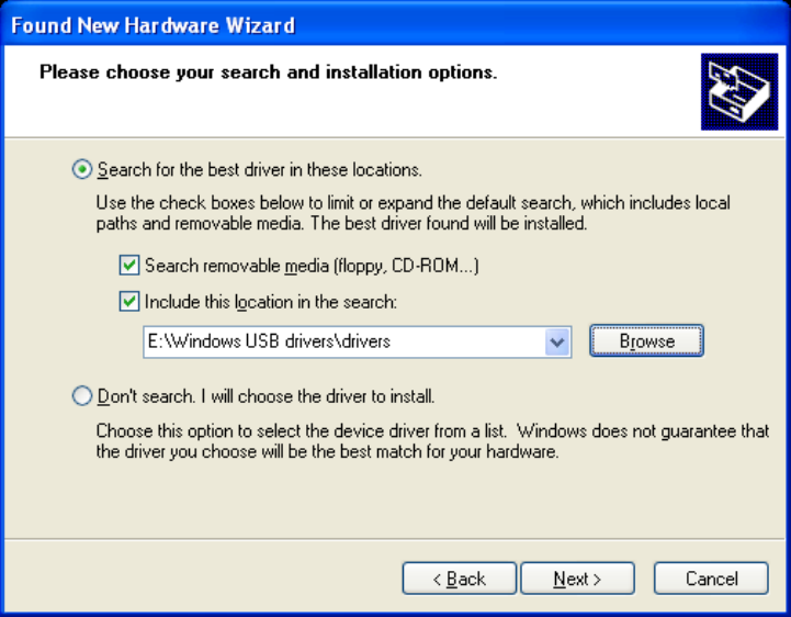
Figure: 17 - Hardware Wizard – Search for best driver
9. Click on the check box marked Include this location in the search.
10. Browse to the location on your computer where the USB drivers are located.
11. Click Next.
12. You will see the screen that shows the installation progress:
- 42 -
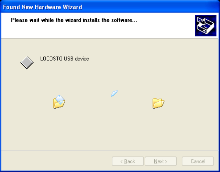
Figure: 18 - Hardware Wizard – Install Progress
13. When the installation of the Locosto USB device is complete, you will see the following screen:
- 43 -

Figure: 19 - Hardware Wizard – Completing
14. Click Finish.
When this installation is complete, the installation process for the USB device will begin. You will see the
following screen:
- 44 -

Figure: 20 - Hardware Wizard – Install from specific location
15. Click on No, not this time.
16. Click Next.
17. You will see the following screen:
- 45 -
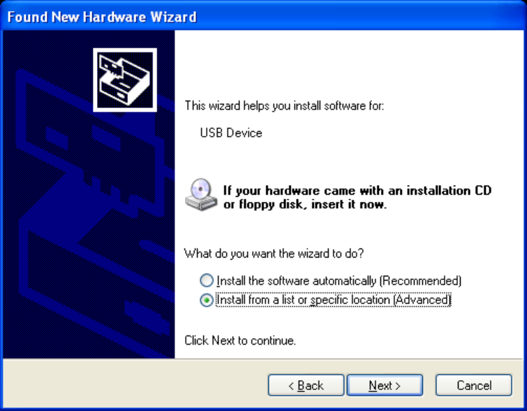
Figure: 21 - Hardware Wizard – Install from List
18. Click the radio button next to Install from a list or specific location (Advanced).
19. Click Next.
20. You will see the following screen:
- 46 -
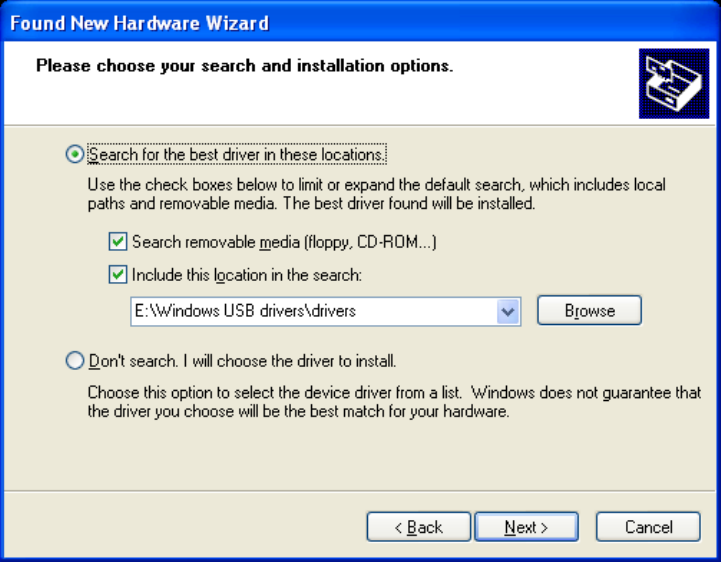
Figure: 22 - Hardware Wizard – Search for best driver
21. Click on the check box marked Include this location in the search.
22. Browse to the location on your computer where the USB drivers are located.
23. Click Next.
24. You may see the following screen:
- 47 -
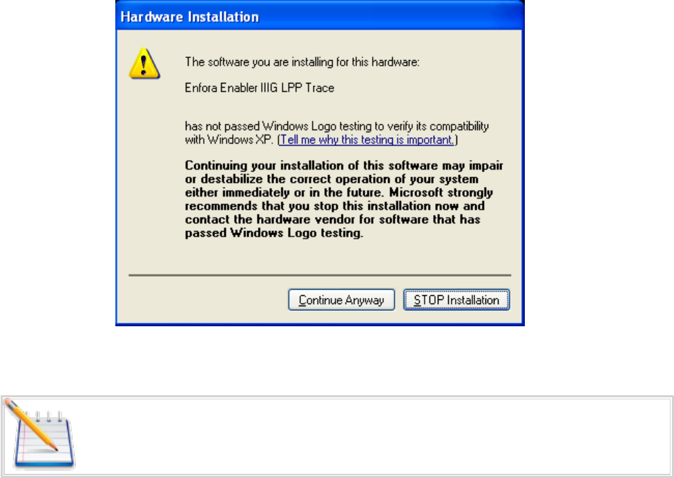
Figure: 23 - Hardware Wizard – Windows Logo testing
Note: If you see this warning, click on Continue Anyway
25. You will see the screen that shows the installation progress:
- 48 -
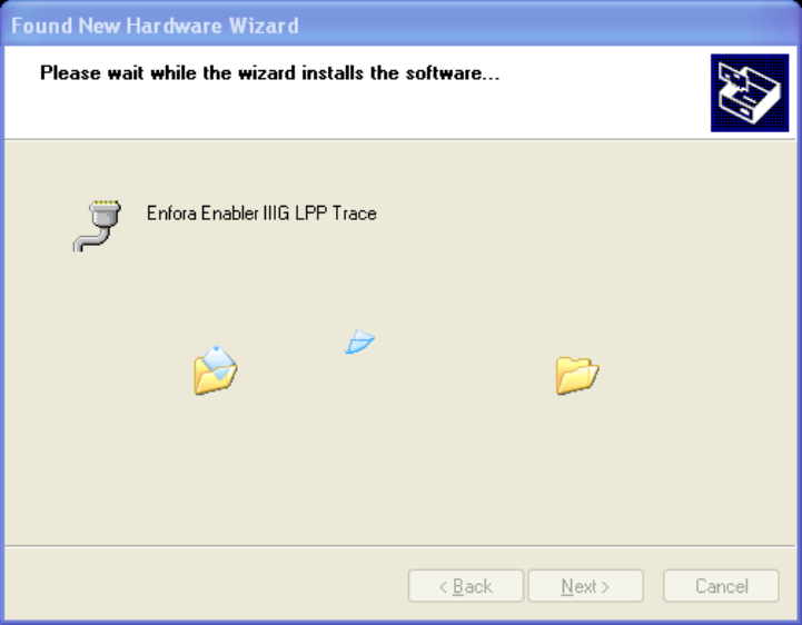
Figure: 24 - Hardware Wizard – Installation Progress
26. When the installation of the Enfora® Enabler®III LPP Trace is complete, you will see the following
screen:
- 49 -
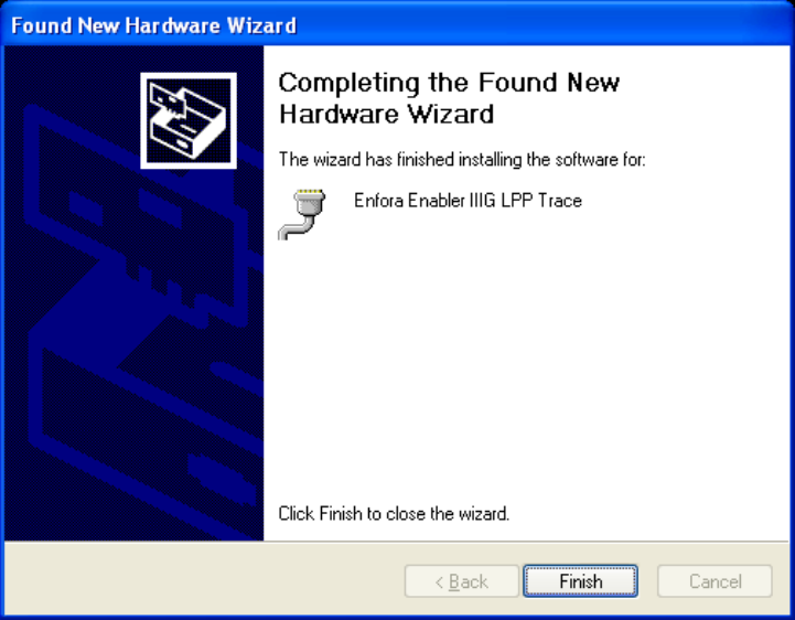
Figure: 25 - Hardware Wizard – Installation Complete
27. Click Finish.
When this installation is complete, the installation process for the USB device will begin. You will see the
following screen:
- 50 -

Figure: 26 - Hardware Wizard – New Hardware
28. Click on No, not this time.
29. Click Next.
30. You will see the following screen:
- 51 -
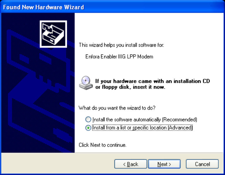
Figure: 27 - Hardware Wizard – Install from List
31. Click the radio button next to Install from a list or specific location (Advanced).
32. Click Next.
33. You will see the following screen:
- 52 -

Figure: 28 - Hardware Wizard – Search for best driver
34. Click on the check box marked Include this location in the search.
35. Browse to the location on your computer where the USB drivers are located.
36. Click Next.
37. You may see the following screen:
- 53 -
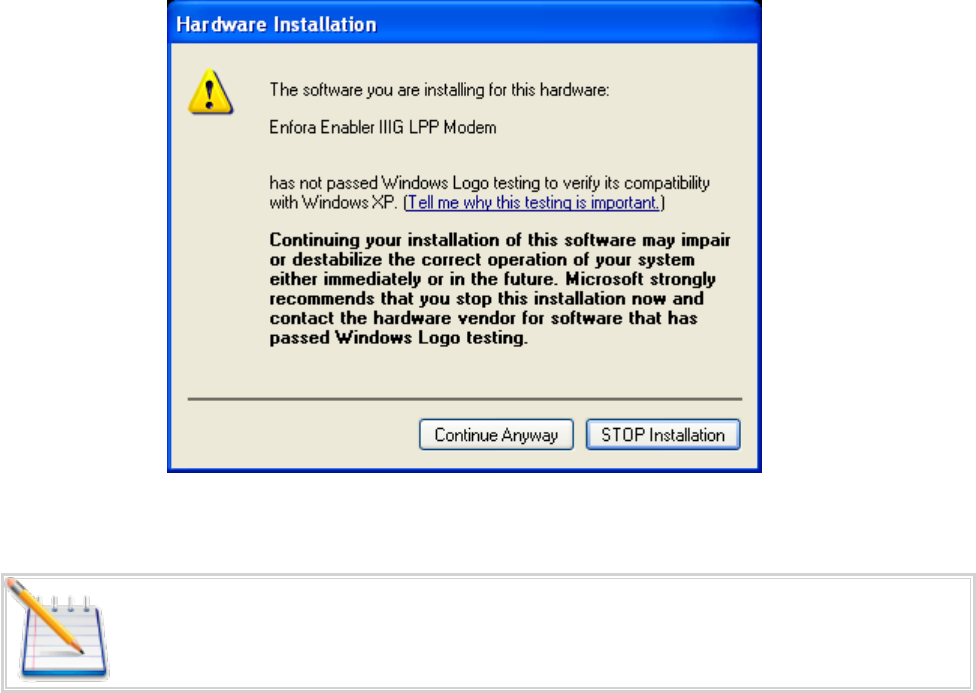
Figure: 29 - Hardware Wizard – Windows Logo testing
Note: If you see this warning, click on Continue Anyway
- 54 -

Figure: 30 - Hardware Wizard – Installation Complete
38. Click Finish to complete the installation of the Enfora® Enabler®III LPP Modem drivers.
- 55 -
9 SIM Card Installation
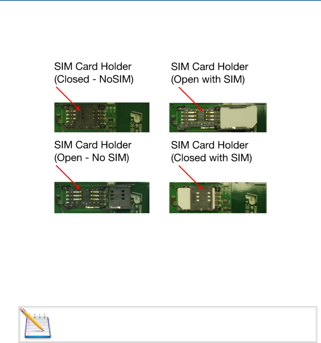
9.1 SIMCard Holder
The SIM holder is located inside the Spider AT 3000. It is a standard flip-type SIM holder that must be
completely closed in order for the SIM card to make a secure connection.
Figure: 31 - Spider AT 3000 SIM Holder
9.2 SIM Card Installation
1. Slide the SIM card into the open SIM holder.
2. Make sure the SIM card notch is lined up properly ( See 9 "SIM Card Installation" ).
3. Close the holder, and slide it until it is completely closed.
Note: The SIM card is not provided with the Spider AT 3000 device. The SIM must be
obtained from the GSM/GPRS service provider and must be provisioned by the
operator for data. Always take care to protect the SIM
- 56 -
- 57 -