Novatel 01019126 Wireless GNSS Receiver with Bluetooth User Manual OM 20000150 SMART6
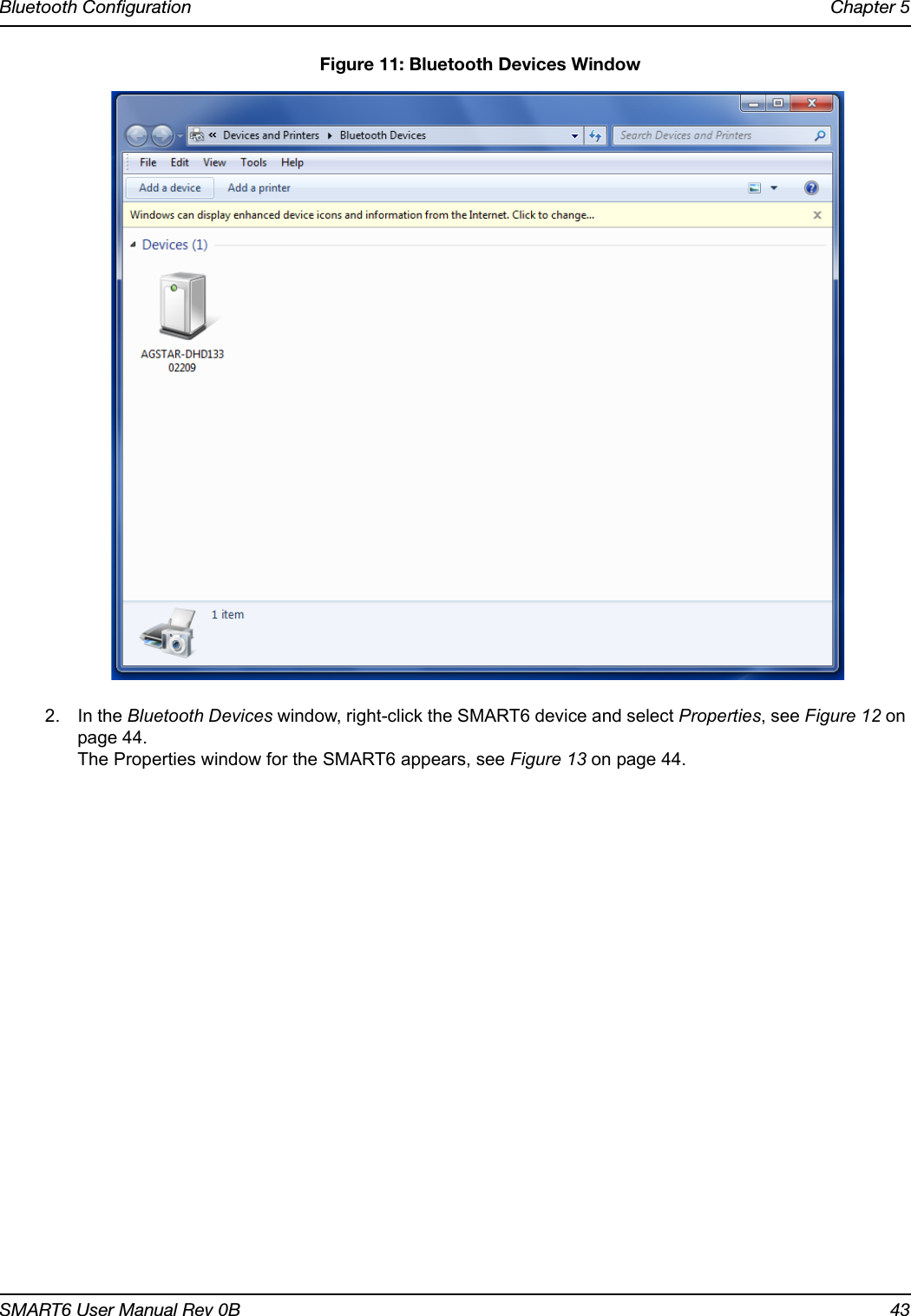
Novatel Inc Wireless GNSS Receiver with Bluetooth OM 20000150 SMART6
Novatel >
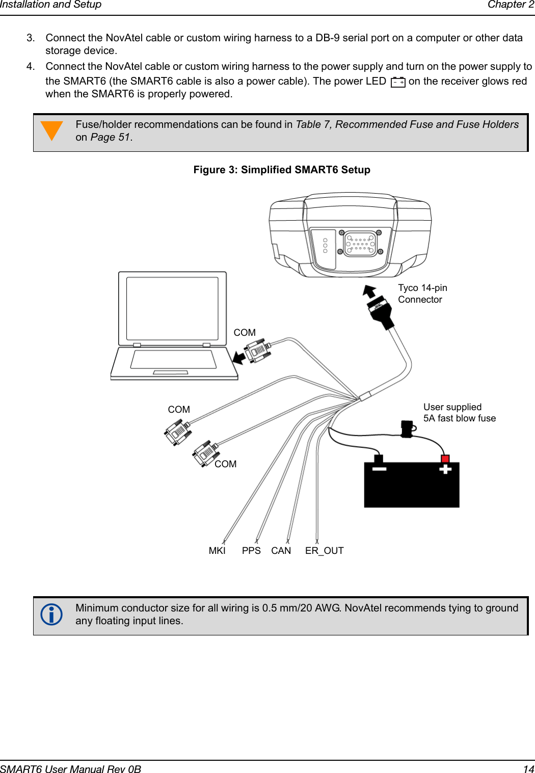
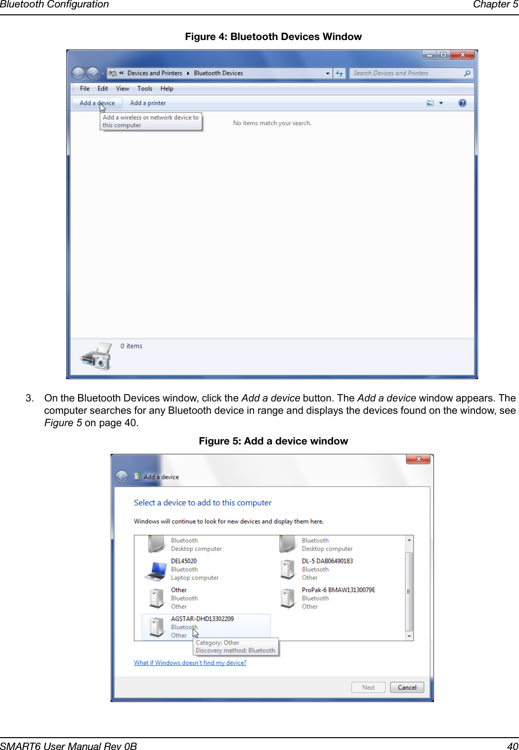
Contents
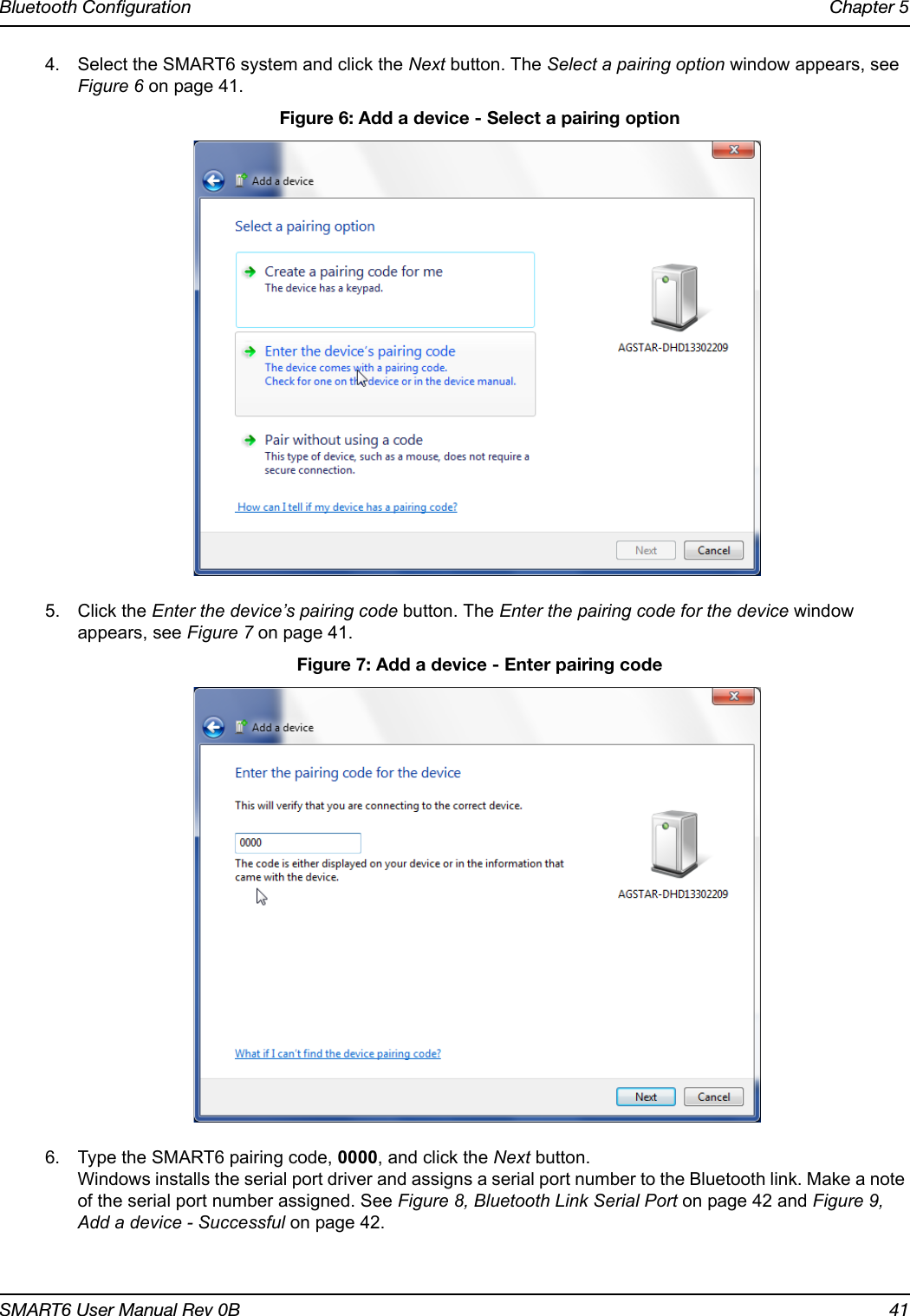
- 1. Agstar user manual
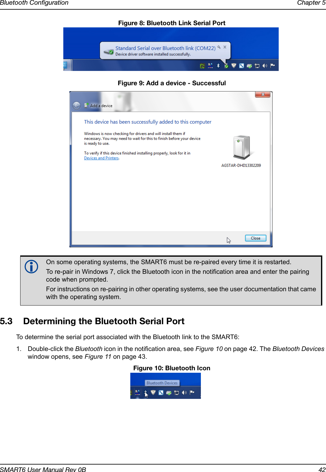
- 2. Smart6 user manual
Smart6 user manual


![Customer ServiceSMART6 User Manual Rev 0B 10ConventionsConventions used in this manual are the following:• The letter H in the Offset columns of the commands and logs tables represents the header length for that command or log. Refer to the OEM6 Family Firmware Reference Manual for ASCII and binary header details.• The number following 0x is a hexadecimal number.• Command descriptions’ brackets, [ ], represent the optionality of parameters.• In tables where values are missing they are assumed to be reserved for future use.• Status words are output as hexadecimal numbers and must be converted to binary format (and in some cases then also to decimal). For an example of this type of conversion, refer to the RANGE log in the OEM6 Family Firmware Reference Manual.Conversions and their binary or decimal results are always read from right to left. For a complete list of hexadecimal, binary and decimal equivalents, refer to Unit Conversion available on our web site at www.novatel.com/support/knowledge-and-learning/.Note that provides information to supplement or clarify the accompanying text.Caution that a certain action, operation or configuration may result in incorrect or improper use of the product.Warning that a certain action, operation or configuration may result in regulatory noncompliance, safety issues or equipment damage.](https://usermanual.wiki/Novatel/01019126.Smart6-user-manual/User-Guide-2118708-Page-10.png)


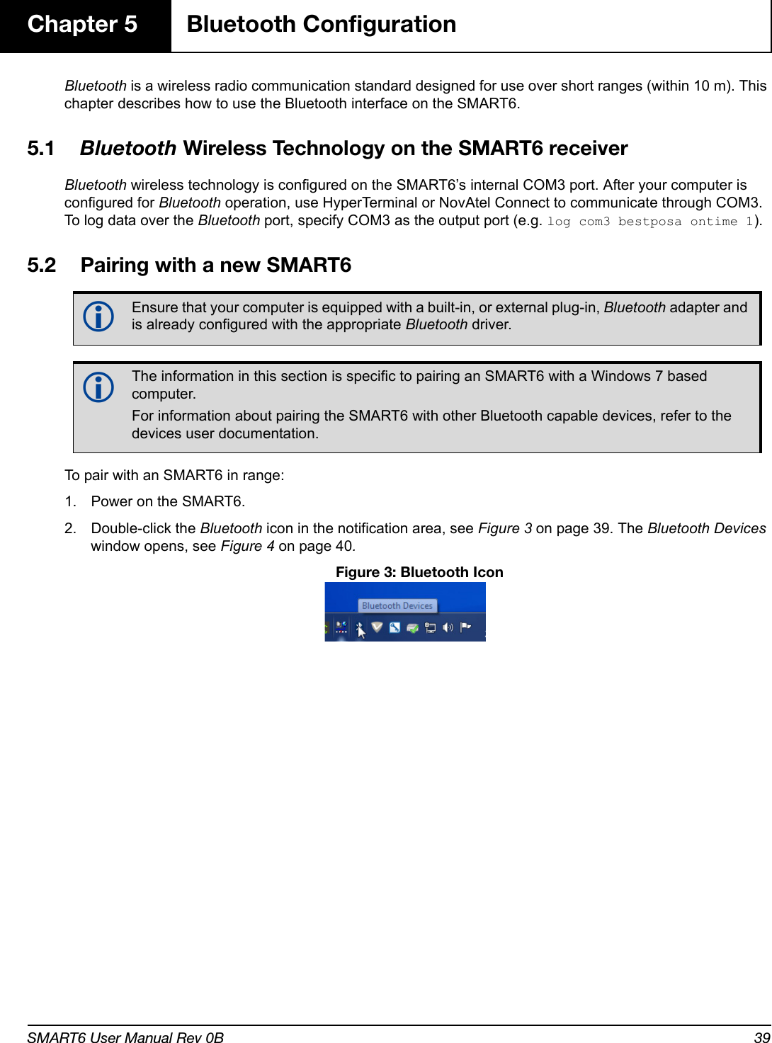
![Operation Chapter 3SMART6 User Manual Rev 0B 233.2 Getting Started3.2.1 Starting the ReceiverWhen first powered, the SMART6 undergoes a complete self-test. The results of this test can be viewed by connecting to the receiver and requesting the RXSTATUS log. Refer to the OEM6 Family Firmware Reference manual for details. If a persistent error develops, contact your local NovAtel dealer first. If the problem remains unresolved, contact NovAtel directly through any of the methods listed in the Customer Service section on page 9.3.2.2 Communicating with the Receiver Using NovAtel ConnectNovAtel Connect is a Windows based GUI used to access the receiver's many features. Convert is a utility that converts between file formats and strips unwanted records for data file compilation. Both are included in the NovAtel Connect PC Utilities bundle available from: www.novatel.com/support/firmware-software-and-manuals/firmware-software-updates/.Launch the NovAtel Connect program and select Device | Open Connect from its main menu. The Open Connection window appears. Figure 8: Open Connection WindowRefer to the NovAtel Connect help file or press F1 while the cursor is in a NovAtel Connect window. Ensure the Console and ASCII Messages windows are open by selecting them from the View menu.When the receiver is first turned on, no data is transmitted from the COM ports except for the port prompt. The console window displays a port name:[COM1] if connected to COM1 port[COM2] if connected to COM2 port[COM3] if connected to COM3 port or through BluetoothAny of the above prompts indicate the receiver is ready and waiting for command input.1. You may also have to wait for output from receiver self-tests. For example, on start-up, the SMART6 is set to log the RXSTATUSEVENTA log ONNEW on all ports. Refer to the OEM6 Family Firmware Reference Manual for more details.2. If NovAtel Connect is unable to locate the SMART6, try using a different COM port to communicate to the receiver. Once communication has been established, issue the FRESET STANDARD command. You should now be able to use the original communication port again.](https://usermanual.wiki/Novatel/01019126.Smart6-user-manual/User-Guide-2118708-Page-23.png)
![Operation Chapter 3SMART6 User Manual Rev 0B 24Commands are typed at the interfacing computing device’s keypad and executed after issuing a carriage return command which is usually the same as pressing the <Enter> key.An example of a response to an input command is the FIX POSITION command. It can be as:[COM2] FIX POSITION 51.11635 -114.0383 1048.2 [Carriage Return]<OKwhere [COM2] is the port prompt, followed by the command entered and [Carriage Return] is a prompt to press the <Enter> key.The example above illustrates the command input to the base receiver’s COM2 port, which sets the position of the base station receiver for differential operation. Confirmation that the command was actually accepted is the appearance of <OK.If a command is entered incorrectly, the receiver responds with:<Invalid Message ID (or a more detailed message)3.3 Transmitting and Receiving CorrectionsRTK or DGPS corrections can be transmitted from a base station to a rover station to improve position accuracy. The base station is the GNSS receiver, which is acting as the stationary reference. It has a known position and transmits correction messages to the rover station. The rover station is the GNSS receiver which does not know its exact position and can be sent correction messages from a base station to calculate differential GNSS positions. The SMART6 can be used as a base receiver to transmit RTK or DGPS corrections or a rover to receive the same corrections. An example of a differential setup is given in Figure 9, Basic Differential Setup on page 25.Ensure the computer’s Control Panel Power Settings are not set to Hibernate or Standby modes. Data is lost if one of these modes occurs during a logging session.](https://usermanual.wiki/Novatel/01019126.Smart6-user-manual/User-Guide-2118708-Page-24.png)
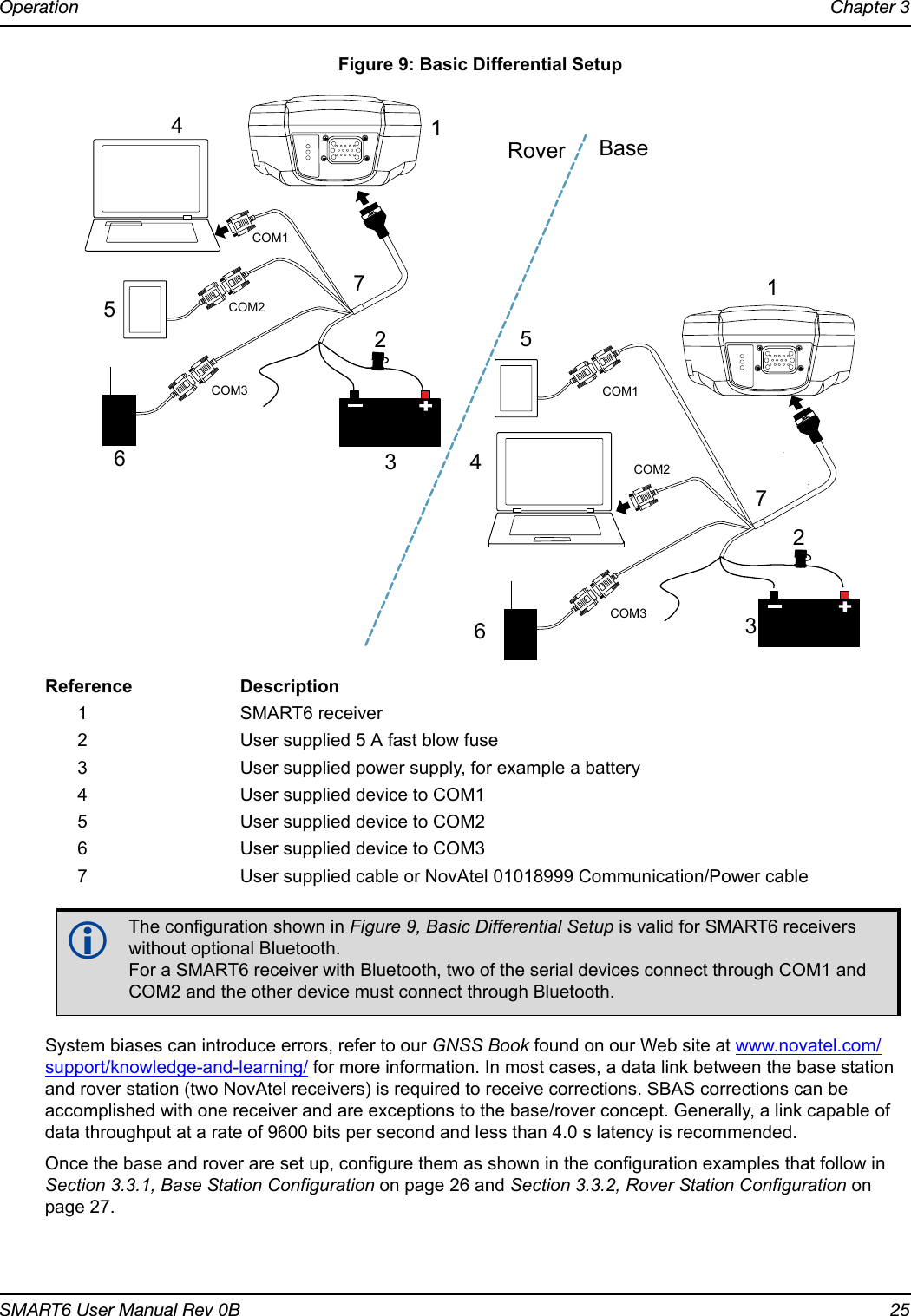
![Operation Chapter 3SMART6 User Manual Rev 0B 263.3.1 Base Station ConfigurationAt the base station, enter the following commands:COM [port] bps [parity[databits[stopbits[handshake[echo[break]]]]]]interfacemode port rx_type tx_type [responses]fix position latitude longitude heightlog port message [trigger [period]]Examples of these commands include the following:RTCA com com2 9600 N 8 1 N off interfacemode com2 none rtca offfix position 51.11358042 -114.04358013 1059.4105log com2 rtcaobs ontime 1log com2 rtcaref ontime 10log com2 rtca1 ontime 5 (optional for RTK)log com2 rtcaephem ontime 10 1 (optional)RTCM com com2 9600 N 8 1 N off interfacemode com2 none rtcm offfix position 51.11358042 -114.04358013 1059.4105log com2 rtcm3 ontime 10 (required for RTK)log com2 rtcm22 ontime 10 1 (optional)log com2 rtcm1819 ontime 1log com2 rtcm1 ontime 5RTCMV3 com com2 9600 N 8 1 N off interfacemode com2 none rtcmv3 offfix position 51.11358042 -114.04358013 1059.4105log com2 rtcm1006 ontime 10log com2 rtcm1003 ontime 1CMR+ com com2 9600 N 8 1 N off interfacemode com2 none cmr offfix position 51.11358042 -114.04358013 1059.4105log com2 cmrobs ontime 1log com2 cmrplus ontime 1 (Important to use ontime 1 with cmrplus)CMR com com2 9600 N 8 1 N off interfacemode com2 none cmr offfix position 51.11358042 -114.04358013 1059.4105log com2 cmrobs ontime 1log com2 cmrref ontime 10log com2 cmrdesc ontime 10 1](https://usermanual.wiki/Novatel/01019126.Smart6-user-manual/User-Guide-2118708-Page-26.png)
![Operation Chapter 3SMART6 User Manual Rev 0B 273.3.2 Rover Station ConfigurationAt the rover station, enter:COM [port] bps [parity[databits[stopbits[handshake[echo[break]]]]]]interfacemode port rx_type tx_type [responses]For example:RTCA interfacemode com2 rtca none offRTCM interfacemode com2 rtcm none offRTCMV3 interfacemode com2 rtcmv3 none offCMR+ interfacemode com2 cmr none offCMR interfacemode com2 cmr none off (same as CMR+)3.3.3 GPS + GLONASS Base and Rover ConfigurationThis section shows how to set up a base and rover OEM6 GPS + GLONASS enabled receivers for GPS + GLONASS RTK operation: Base Station: fix position lat lon hgt (enter your own lat, lon, and hgt values)com com2 9600 N 8 1 N off interfacemode com2 none rtca off log com2 rtcaref ontime 10 log com2 rtcaobs2 ontime 1 log com2 rtca1 ontime 5 (optional, enable code-DGPS coverage)saveconfig (optional, save configuration to non-volatile memory)Rover Station: com com2 9600 N 8 1 N off interfacemode com2 rtca none off log com1 bestposa ontime 1 (optional, view position information) saveconfig (optional, save configuration to non-volatile memory)](https://usermanual.wiki/Novatel/01019126.Smart6-user-manual/User-Guide-2118708-Page-27.png)
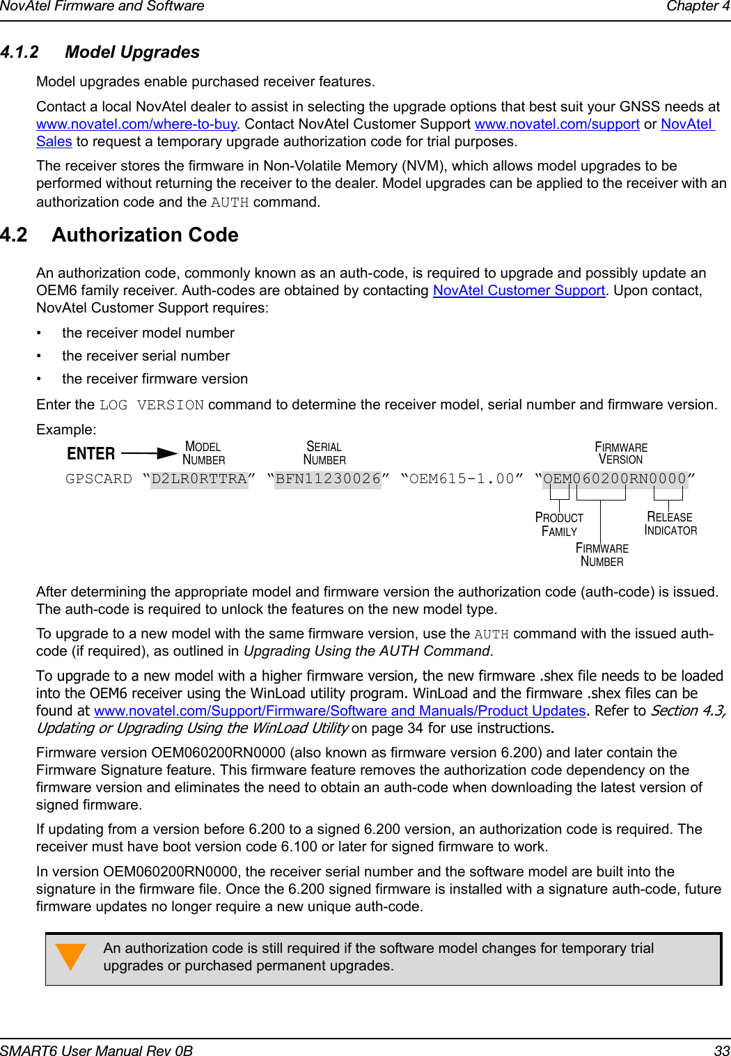
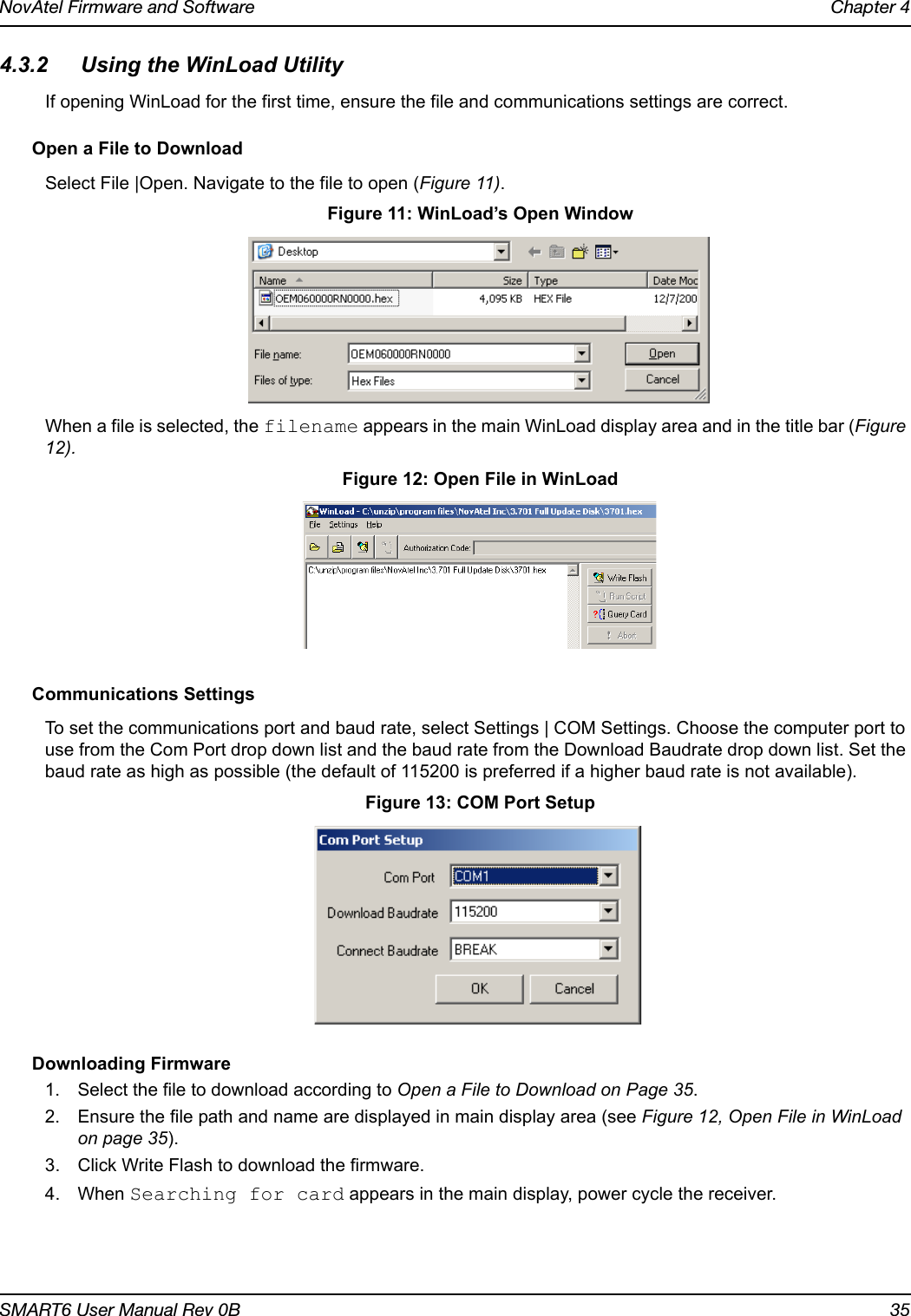
![NovAtel Firmware and Software Chapter 4SMART6 User Manual Rev 0B 34The new download package includes a signed firmware file type that uses an extension designated as “.shex” (example OEM060200RN0000.shex), as well as the latest Winload utility and What’s New file containing firmware update change details.4.3 Updating or Upgrading Using the WinLoad UtilityWinLoad is the simplest and most common way to update or upgrade an OEM6 receiver.4.3.1 Transferring Firmware FilesTo proceed with an update or possibly an upgrade, obtain the latest version of firmware from the NovAtel website at www.novatel.com/support/firmware-software-and-manuals/firmware-software-updates/oem6-family/.Types of Firmware Files•OEM Version - NovAtel Customer Service may generate and provide the required authorization code. Authorization codes are obtained by contacting support@novatel.com or at www.novatel.com/Support/.The OEM version is named OEMXXXX.EXE, where XXXX is the firmware version.For convenience, copy the update file to a GNSS sub-directory (for example, C:\GNSS\LOADER).If the firmware update file is password protected, NovAtel Customer Support provides the required password. After copying the file to a computer, perform the following steps to extract the files:Syntax: [filename] [password] (if required)where filename is the name of the compressed file (but not including the .EXE extension) and password if the password is required for extraction.Example: OEM060200RN0000.shexIn the above example, a window appears asking for a password.The self-extracting archive produces the following files:winload.exe WinLoad utility programhowto.txt Instructions on how to use the WinLoad utilitywhatsnew.rtf Information on the changes made in the firmware since the last revisionx..x.shex Firmware version upgrade file, where x..x defines the product name and release (e.g., OEM060000RN0000.shex)The files are extracted to unzip/program files/NovAtel Inc/x.xxx Full Update Disk, where x.xxx is the firmware version.Prior to firmware version OEM060200RN0000, authorization codes depended on the software model, the firmware version and the serial number of the receiver. The authorization code changed if any of the three items changed. This is no longer the case.NovAtel has an online video tutorial that explains firmware uploading at: www.novatel.com/support/knowledge-and-learning/video-tutorials-and-tech-presentations/.](https://usermanual.wiki/Novatel/01019126.Smart6-user-manual/User-Guide-2118708-Page-34.png)
![SMART6 User Manual 52Appendix B CommandsThe SMART6 firmware implements the OEM6 family command set, documented in the OEM6 Family Firmware Reference Manual. Commonly used SMART6 commands are summarized in Table 8, SMART6 Commands and documented in this appendix. Table 8: SMART6 CommandsThe arguments for each of these commands are described in the following sections.For a complete listing and description of the other commands that the SMART6, an OEM6 based receiver, is capable of processing, refer to the OEM6 Family Firmware Reference Manual.B.1 SYNTAX CONVENTIONSThe following rules apply when entering commands, at the command prompt, from a keyboard.1. Courier font is used to illustrate program output or user input.2. References to other commands, logs or any of their fields are shown in italics.3. The commands are not case sensitive. For example, you could type either RESET or reset.4. Except where noted, either a space or a comma can separate commands and their required entries. For example, you could type either fix position 51.11358042 -114.04358013 1059.4105 or fix position 51.11358042, -114.04358013, 1059.4105.5. At the end of a command, a carriage return is required. For example, press <Enter> or <Return> on your keyboard.6. Responses are provided to indicate whether or not an entered command was accepted. The format of the response depends on the format of the command. Refer to the OEM6 Family Firmware Reference Manual for more information.7. Optional parameters are indicated by square brackets ( [ ] ). For commands that contain optional parameters, the value used if the optional parameter is not specified is given in the syntax table for the command.8. Data format definitions, as specified in the “Format” field, are detailed in the OEM6 Family Firmware Reference Manual. Note that all binary data is little-endian byte-ordered.ASCII Command Message ID DescriptionBTCONTROL 8205 Enable or disable Bluetooth wireless technology.COM 4 Configure the receiver serial port.FRESET 20 Factory reset (existing OEM6 commands extended to SMART6)LOG 1 Request logs from the receiver $PMDT 8200 Configure the Tilt Compensation function (SMART6 command)RADARCFG 8192 Configure the Emulated Radar signal output (SMART6 command)SETCANNAME 1091 Set the CAN name fields.](https://usermanual.wiki/Novatel/01019126.Smart6-user-manual/User-Guide-2118708-Page-52.png)
![SMART6 User Manual Rev 0B 54B.3 COM Configure COM PortThis command is used to configure the receiver’s serial ports.The current COM port configuration can be reset to the default state at any time by sending two hardware break signals of 250 milliseconds each, spaced by fifteen hundred milliseconds (1.5 seconds), with a pause of at least 250 milliseconds following the second break. This will:• Stop the logging of data on the current port (see UNLOGALL command in the OEM6 Family Firmware Reference Manual).• Clear the transmit and receive buffers on the current port.• Return the current port to its default settings.• Set the interface mode to NovAtel for both input and output (see INTERFACEMODE command in the OEM6 Family Firmware Reference Manual).Message ID: 4Abbreviated ASCII SyntaxCOM [port] bps [parity[databits[stopbits[handshake[echo[break]]]]]]Factory Default:COM COM1 9600 N 8 1 N OFF ONCOM COM2 9600 N 8 1 N OFF ONCOM COM3 9600 N 8 1 N OFF ON ASCII Example:COM COM1 57600 N 8 1 N OFF ON Baud rates higher than 115,200 bps are not supported by standard computer hardware. Special computer hardware may be required for higher rates, including 230400 bps, 460800 bps and 921600 bps. Also, some computers have trouble with baud rates beyond 57600 bps.On SMART6 receivers with Bluetooth wireless technology, the default settings for COM3 are:com3 115200 n 8 1 cts off offChanging the COM3 serial port settings could interfere with the ability to communicate using Bluetooth.Use the COM command before using the INTERFACEMODE command on each port. Watch for situations where the COM ports of two receivers are connected together and the baud rates do not match. Data transmitted through a port operating at a slower baud rate may be misinterpreted as break signals by the receiving port if it is operating at a higher baud rate.This is because data transmitted at the lower baud rate is stretched relative to the higher baud rate. In this case, configure the receiving port to have break detection disabled using the COM command.](https://usermanual.wiki/Novatel/01019126.Smart6-user-manual/User-Guide-2118708-Page-54.png)
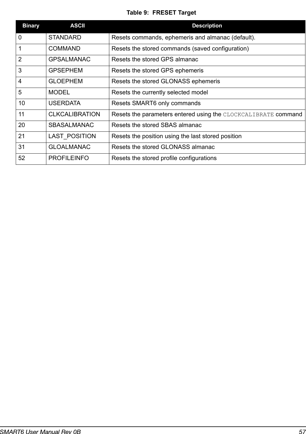
![SMART6 User Manual Rev 0B 56B.4 FRESET Clear Selected Data from NVM and ResetThis command clears data that is stored in non-volatile memory. Such data includes the almanac, ephemeris and any user specific configurations. The commands, ephemeris and almanac related data can be cleared by using the STANDARD target. The model can only be cleared by using the MODEL target. The receiver is forced to hardware reset. In addition, values entered using the CLOCKCALIBRATE command can only be cleared by using the CLKCALIBRATION target.Issuing the FRESET command affects Tilt as follows:• Tilt sensor level is restored to the factory default• Tilt enable/disable is not be affectedMessage ID: 20Abbreviated ASCII Syntax:FRESET [target]Input Example:FRESET COMMANDFRESET STANDARD (which is also the default) causes any commands, ephemeris, GNSS and almanac data previously saved to NVM to be erased.If you are receiving no data or random data from your receiver, try the following before contacting NovAtel:• Verify that the receiver is tracking satellites• Check the integrity and connectivity of power and data cables• Verify the baud rate settings of the receiver and terminal device (your computer or data logger)• Switch COM ports• Issue a FRESET command Field Field Type ASCII ValueBinary Value Description Binary FormatBinary BytesBinary Offset1FRESET header- - This field contains the command name or the message header depending on whether the command is abbreviated ASCII, ASCII or binary.- H 02target See Table 9, FRESET Target on Page 57What data is to be reset by the receiver.(default=STANDARD)Enum 4 H](https://usermanual.wiki/Novatel/01019126.Smart6-user-manual/User-Guide-2118708-Page-56.png)
![SMART6 User Manual Rev 0B 58B.5 LOG Request Logs from the ReceiverMany different types of data can be logged using several different methods of triggering the log events. Every log element can be directed to any combination of the three COM ports. The ONTIME trigger option requires the addition of the period parameter. See the OEM6 Family Firmware Reference Manual for further information and a complete list of data log structures. The LOG command tables in this section show the ASCII command format.The optional parameter [hold] prevents a log from being removed when the unlogall command, with its defaults, is issued. To remove a log that was invoked using the [hold] parameter requires the specific use of the unlog command. To remove all logs that have the [hold] parameter, use the UNLOGALL command with the held field set to 1.The [port] parameter is optional. If [port] is not specified, [port] is defaulted to the port that the command was received on.Message ID: 1Abbreviated ASCII Syntax:LOG [port] message [trigger [period [offset [hold]]]]Abbreviated ASCII Example 1:LOG COM1 BESTPOS ONTIME 7 0.5 HOLDThe above example shows BESTPOS logging to COM port 1 at 7 second intervals and offset by 0.5 seconds (output at 0.5, 7.5, 14.5 seconds and so on). The [hold] parameter is set so logging is not disrupted by the unlogall command.To send a log only one time, the trigger option can be ignored. Abbreviated ASCII Example 2:LOG COM1 BESTPOS ONCE 0.000000 0.000000 NOHOLDRefer to the Command Formats section of the OEM6 Family Firmware Reference Manual for additional examples.1. The OEM6 family of receivers can handle 64 logs at a time. If it is more than 64 logs at a time, the receiver responds with an Insufficient Resources error.2. Maximum flexibility for logging data is provided to the user by these logs. The user is cautioned, however, to recognize that each log requested requires additional CPU time and memory buffer space. Too many logs may result in lost data and degraded CPU performance. Receiver overload can be monitored using the idle time field and buffer overload bits of the Receiver Status in any log header.3. Polled log types do not allow fractional offsets or ONTIME rates faster than 1 Hz.4. Use the ONNEW trigger with the MARKTIME or MARKPOS logs.5. Only the MARKPOS or MARKTIME logs and ‘polled’ log types are generated, on the fly, at the exact time of the mark. Synchronous and asynchronous logs output the most recently available data.6. If the ONTIME trigger is used with asynchronous logs, the time stamp in the log does not necessarily represent the time the data was generated but rather the time when the log is transmitted.1. In NovAtel Connect there are two ways to initiate data logging to the receiver's serial ports:- the LOG command in the Console window or - use the interface provided in the Logging Control window. 2. Only the ASCII/Abbreviated ASCII log table is included in this manual. Refer to the LOG command in the OEM6 Family Firmware Reference Manual for binary log details.](https://usermanual.wiki/Novatel/01019126.Smart6-user-manual/User-Guide-2118708-Page-58.png)
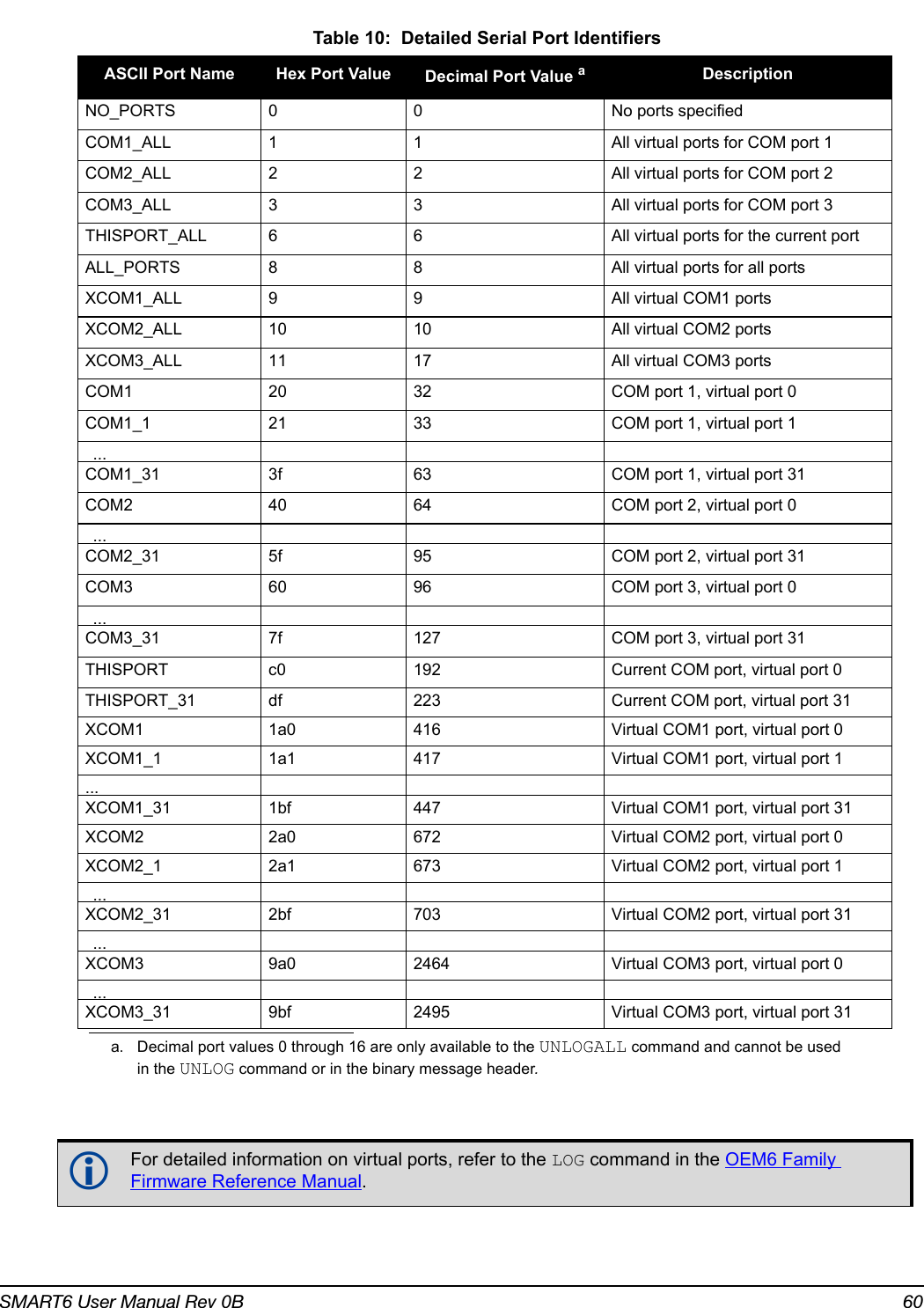
![SMART6 User Manual Rev 0B 59Factory Default:LOG COM1 RXSTATUSEVENTA ONNEW 0 0 HOLDLOG COM2 RXSTATUSEVENTA ONNEW 0 0 HOLDLOG COM3 RXSTATUSEVENTA ONNEW 0 0 HOLD Field Field Name ASCII Value Description Field Type1LOG (ASCII) header- This field contains the command name or the message header depending on whether the command is abbreviated ASCII or ASCII respectively-2 port See Table 10, Detailed Serial Port Identifiers on page 60Output port(default = THISPORT)Enum3 message Any valid message name, with an optional A or B suffixMessage name of log to output Char [ ]4 trigger ONNEW Output when the message is updated (not necessarily changed)EnumONCHANGED Output when the message is changedONTIME Output on a time intervalONNEXT Output only the next messageONCE Output only the current message (default)ONMARK Output when a pulse is detected on the mark 1 input, MK1I 5 period Any positive double value larger than the receiver’s minimum raw measurement periodLog period (for ONTIME trigger) in seconds(default = 0)Double6 offset Any positive double value smaller than the periodOffset for period (ONTIME trigger) in seconds. To log data at 1 second after every minute, set the period to 60 and the offset to 1 (default = 0)Double7hold NOHOLD Allow log to be removed by the UNLOGALL command (default)EnumHOLD Prevent log from being removed by the UNLOGALL command](https://usermanual.wiki/Novatel/01019126.Smart6-user-manual/User-Guide-2118708-Page-59.png)
![SMART6 User Manual Rev 0B 61B.6 $PMDT Configure Tilt CompensationUse this NMEA command to configure the Tilt Compensation function.Syntax$PMDT,[command],[parameters]*cksumRefer to Tilt Compensation on page 19 and Tilt Compensation on page 30 for setup instructions.Host Description Command Format Tilt Sensor Responseua bSet GPS Sensor HeightTo set the GNSS sensor height in feet and inches:$PMDT,u,,ff,ii*cksum crlfExample: To set the GNSS sensor height to 12 ft 6 in, the command is:$PMDT,u,,12,6*40Note: Feet and inches are entered as integers. You can enter feet and inches, but not feet, inches and metres.Response to the “u” command:$PMDT,<,GNSS sensor height (inches):nnnnn crlfwhere nnnnn is a five digit integer, sensor height in inches.In this example, the Tilt Sensor response is:$PMDT,<,GNSS sensor height (inches): 00150To set the GNSS sensor height in metres:$PMDT,u,,,,mmm.mmm*cksum crlfExample: To set the GNSS sensor height to 3.5 metres, the command is:$PMDT,u,,,,3.5*7CResponse to the ”u” command:$PMDT,<,GNSS sensor height (inches):nnnnn crlfwhere nnnnn is a five digit integer, sensor height in inches.In this example, the Tilt Sensor response is:$PMDT,<,GNSS sensor height (inches): 00137l Set Field Level $PMDT,l*cksum crlfExample:$PMDT,l*4DResponse to the “l” command:$PMDT,<,Level state set crlfExample:$PMDT,<,Level state setx Update Flash ValuesTo update flash values (needs to follow any height or level command that is not done each time you power up):$PMDT,x*cksum crlfExample: $PMDT,x*59Response to the “x” command:$PMDT,<,Flash updated crlfExample:$PMDT,<,Flash updateda. If all fields in the u command are zero or null, the current height is transmitted without change (with the format shown above).b. If an invalid entry is received (>500 inches), the response is:$PMDT,<Max legal height exceeded: nnnnn and will be ignored clrfFor example, if you enter 42 ft 6 in, you will get the following response:$PMDT,<,Max legal height exceeded: 00510 and will be ignored$PMDT,<,GPS sensor height (inches): 00150](https://usermanual.wiki/Novatel/01019126.Smart6-user-manual/User-Guide-2118708-Page-61.png)
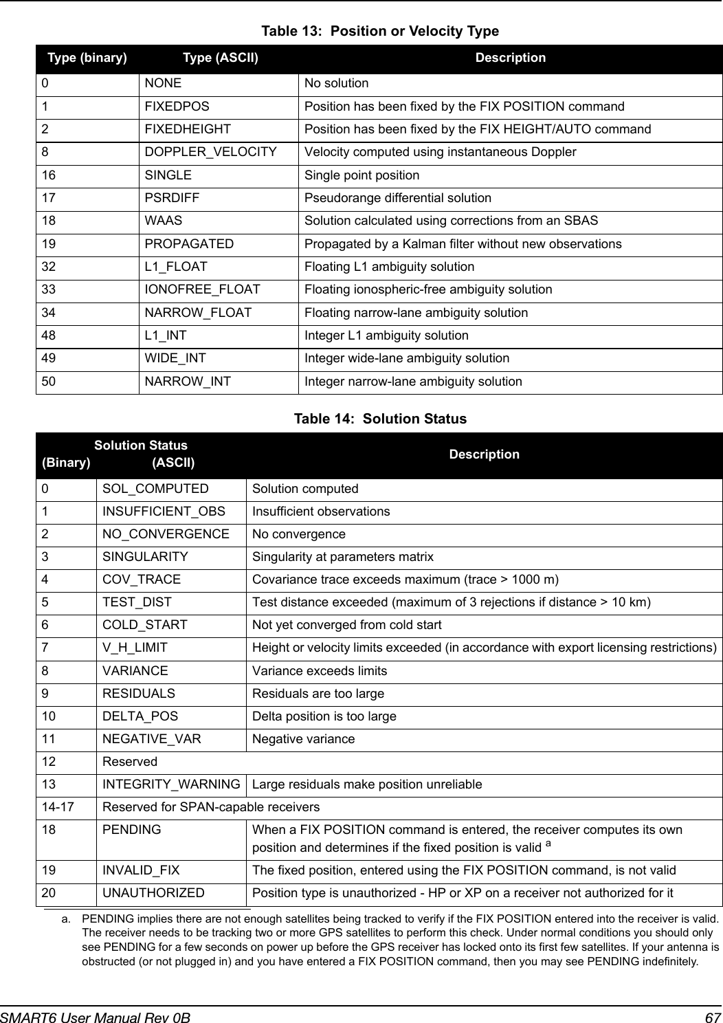
![SMART6 User Manual Rev 0B 66C.2.1 RADARSIGNAL ER Signal and Position InformationThis log contains position and Emulated Radar (ER) signal information.Message ID: 8193Log Type: AsynchRecommended Input:log radarsignala onchangedASCII Example 1 (stationary SMART6):#radarsignala,com1,0,61.5,finesteering,1501,248381.628,00000000,8a1c,3723;sol_computed,waas,0.0139,0.00,0.00*f0d580caASCII Example 2 (moving SMART6):#radarsignala,com1,0,42.5,finesteering,1428,206179.600,00000000,baa8,3349;sol_computed,waas,0.3315,2,0.3152,473.97,29.62*c1479c20Field #Field type Data Description Format Binary BytesBinary Offset1 RADARSIGNAL headerLog header H 02 sol status Solution status, see Table 14, Solution Status on page 67 Enum 4 H3 vel type Velocity type, see Table 13, Position or Velocity Type on page 67Enum 4 H+44 speed Speed over ground (m/s) Double 8 H+84 varf freq External VARF output frequency (Hz) Double 8 H+165 radar freq Radar signal frequency (Hz) as output by the Emulated Radar Out signal. See Section B.7, RADARCFG Configure the ER Output on page 62.Double 8 H+246 xxxx 32-bit CRC (ASCII and Binary only) Hex 4 H+327 [CR][LF] Sentence terminator (ASCII only) - - -](https://usermanual.wiki/Novatel/01019126.Smart6-user-manual/User-Guide-2118708-Page-66.png)
![SMART6 User Manual Rev 0B 68C.2.2 TILT CompensationTilt Compensation affects existing logs as follows:• NovAtel logs that provide the Extended Solution Status field (BESTPOS and BESTXYZ, both documented in OEM6 Family Firmware Reference Manual) use the 0x80 bit to flag the fact that Tilt Compensation is being applied.• For NMEA GPGGA, GPGGARTK, and GPGGALONG logs, the precision of various fields indicates whether the Tilt Compensation is being applied.C.2.3 VERSION HW and SW Versions and Serial NumbersThe Component Type of the VERSION log, refer to the OEM6 Family Firmware Reference Manual, is extended to include SMART6 information as in Table 15, Component Type. Table 15: Component Type[COM1]<VERSION COM1 0 85.0 FINESTEERING 1727 510341.712 00000000 3681 10985< 1< GPSCARD "D2LR0GTTR" "BFN12390111" "OEM628-1.01" "OEM060210RN0000" "OEM060200RB0000" "2012/Sep/13" "13:46:16"[COM1]Binary Valueaa. Unused numbers are reserved for future use.ASCII Value Description0 UNKNOWN Unknown Component1 GPSCARD OEM6 GPSCard Component3 ENCLOSURE SMART6 Receiver8 USERINFO User application information component981073925 (0x3A7A0005)DB_USERAPPAUTO Auto-starting user application firmware](https://usermanual.wiki/Novatel/01019126.Smart6-user-manual/User-Guide-2118708-Page-68.png)