Novatel 01019126 Wireless GNSS Receiver with Bluetooth User Manual OM 20000150 SMART6
Novatel Inc Wireless GNSS Receiver with Bluetooth OM 20000150 SMART6
Novatel >
Contents
- 1. Agstar user manual
- 2. Smart6 user manual
Smart6 user manual
SMART6™
User Manual
OM-20000150 Rev 0B September 2013

SMART6 User Manual Rev 0B 2
SMART6 User Manual
Revision Level: 0B
Publication Number: OM-20000150
Revision Date: September 2013
Firmware Version: 6.220 (OEM060220RN0000)
Warranty
NovAtel® Inc. warrants that its GNSS products are free from defects in materials and workmanship, subject to
the conditions set forth on our web site: www.novatel.com/products/warranty/.
Antenna Module One (1) Year
Cables and Accessories Ninety (90) Days
Software Warranty One (1) Year
Return Instructions
To return products, refer to the instructions found under the Return Policy tab on the Warranty page:
www.novatel.com/products/warranty/.
Proprietary Notice
Information in this document is subject to change without notice and does not represent a commitment on the
part of NovAtel Inc. The software described in this document is furnished under a licence agreement or non-
disclosure agreement. The software may be used or copied only in accordance with the terms of the
agreement. It is against the law to copy the software on any medium except as specifically allowed in the
license or non-disclosure agreement.
No part of this manual may be reproduced or transmitted in any form or by any means, electronic or
mechanical, including photocopying and recording, for any purpose without the express written permission of
a duly authorized representative of NovAtel Inc.
The information contained within this manual is believed to be true and correct at the time of publication.
AdVance, NovAtel, GLIDE, NovAtel Connect and OEM6 are registered trademarks of NovAtel Inc.
SMART6 is a trademark of NovAtel Inc.
The Bluetooth word mark and logos are registered trademarks owned by Bluetooth SIG, Inc. and any use of
such marks by NovAtel Inc. is under license. All other brand names are trademarks of their respective
holders.
Manufactured and protected under U.S. Patent:
© Copyright 2013 NovAtel Inc. All rights reserved. Unpublished rights reserved under
International copyright laws.
#5,390,207 #6,184,822 B1 #6,664,923 B1
#5,495,499 #6,211,821 B1 #6,922,167 B2
#5,734,674 #6,445,354 B1 #7,250,916
#5,809,064 #6,608,998 B1 #7,738,536 B2
#5,414,729 #6,452,560 B2 #7,738,606 B2
#5,736,961 #6,728,637 B2 #7,885,317 B2
#6,243,409 B1

SMART6 User Manual Rev 0A 3
Table of Contents
Notice 7
Customer Service 9
1 Introduction 11
1.1 Features and Models...................................................................................................................................................11
2 Installation and Setup 13
2.1 Additional Equipment Required ...................................................................................................................................13
2.1.1 SMART6 Setup .................................................................................................................................................13
2.1.2 Power Supply Requirements.............................................................................................................................15
2.1.3 Mounting Plate ..................................................................................................................................................15
2.1.4 Mounting the SMART6 ......................................................................................................................................17
2.1.5 Connecting Data Communications Equipment..................................................................................................17
2.2 Additional Features and Information............................................................................................................................18
2.2.1 Status Indicators................................................................................................................................................18
2.2.2 MKI and PPS Strobes .......................................................................................................................................18
2.2.3 Emulated Radar (ER) ........................................................................................................................................19
2.2.4 Controller Area Network (CAN) .........................................................................................................................19
2.2.5 Tilt Compensation .............................................................................................................................................19
3 Operation 22
3.1 Communications with the Receiver .............................................................................................................................22
3.1.1 Serial Port Default Settings ...............................................................................................................................22
3.1.2 Communicating Using a Remote Terminal........................................................................................................22
3.1.3 Communicating Using a Computer....................................................................................................................22
3.2 Getting Started ............................................................................................................................................................23
3.2.1 Starting the Receiver.........................................................................................................................................23
3.2.2 Communicating with the Receiver Using NovAtel Connect...............................................................................23
3.3 Transmitting and Receiving Corrections......................................................................................................................24
3.3.1 Base Station Configuration................................................................................................................................26
3.3.2 Rover Station Configuration ..............................................................................................................................27
3.3.3 GPS + GLONASS Base and Rover Configuration ............................................................................................27
3.3.4 Configuration Notes...........................................................................................................................................28
3.4 GLIDE..........................................................................................................................................................................29
3.4.1 Dual-Frequency GLIDE .....................................................................................................................................29
3.5 Emulated Radar (ER) ..................................................................................................................................................29
3.6 Tilt Compensation........................................................................................................................................................30
3.7 Recommended Configuration......................................................................................................................................31
4 NovAtel Firmware and Software 32
4.1 Firmware Updates and Model Upgrades .....................................................................................................................32
4.1.1 Firmware Updates .............................................................................................................................................32
4.1.2 Model Upgrades ................................................................................................................................................33
4.2 Authorization Code ......................................................................................................................................................33
4.3 Updating or Upgrading Using the WinLoad Utility .......................................................................................................34
4.3.1 Transferring Firmware Files...............................................................................................................................34
4.3.2 Using the WinLoad Utility ..................................................................................................................................35
4.4 Updating using SoftLoad Commands..........................................................................................................................36
4.4.1 Working with S-Records....................................................................................................................................37
4.5 Upgrading Using the AUTH Command........................................................................................................................38
4.5.1 Upgrade Procedure ...........................................................................................................................................38
5 Bluetooth Configuration 39
5.1 Bluetooth Wireless Technology on the SMART6 receiver...........................................................................................39
5.2 Pairing with a new SMART6........................................................................................................................................39
5.3 Determining the Bluetooth Serial Port .........................................................................................................................42
5.4 Communicate with the SMART6 Using Bluetooth Wireless Technology.....................................................................45

Table of Contents
SMART6 User Manual Rev 0A 4
A Technical Specifications 46
A.1 SMART6 Receiver Performance.................................................................................................................................46
A.2 SMART6 Specifications...............................................................................................................................................47
A.2.1 SMART6 Communication/Power Cable (01018999).........................................................................................49
A.2.2 SMART6 Connector and Cable Requirements .................................................................................................50
B Commands 52
B.1 Syntax Conventions ....................................................................................................................................................52
B.2 BTCONTROL Enable/Disable Bluetooth wireless technology..................................................................................53
B.3 COM Configure COM Port........................................................................................................................................54
B.4 FRESET Clear Selected Data from NVM and Reset................................................................................................56
B.5 LOG Request Logs from the Receiver......................................................................................................................58
B.6 $PMDT Configure Tilt Compensation.......................................................................................................................61
B.7 RADARCFG Configure the ER Output .....................................................................................................................62
B.8 SETCANNAME Sets the CAN name fields...............................................................................................................63
C Logs 64
C.1 Position Logs ..............................................................................................................................................................64
C.1.1 NMEA Logs.......................................................................................................................................................64
C.1.2 NovAtel Position Logs.......................................................................................................................................65
C.2 Other Logs ..................................................................................................................................................................65
C.2.1 RADARSIGNAL ER Signal and Position Information.....................................................................................66
C.2.2 TILT Compensation........................................................................................................................................68
C.2.3 VERSION HW and SW Versions and Serial Numbers...................................................................................68
D Replacement Parts 69
D.1 SMART6 .....................................................................................................................................................................69
D.2 User Manuals..............................................................................................................................................................69
Index 70

SMART6 User Manual Rev 0A 5
Figures
1 SMART6 Receiver .....................................................................................................................................................11
2 SMART6 Connector ..................................................................................................................................................13
3 Simplified SMART6 Setup .........................................................................................................................................14
4 SMART6 Surface Mounting Plate ..............................................................................................................................15
3 SMART6 Pole Mounting Plate ...................................................................................................................................16
5 SMART6 Orientation .................................................................................................................................................17
6 SMART6 Installation ..................................................................................................................................................20
7 SMART6 Orientation .................................................................................................................................................20
8 Open Connection Window .........................................................................................................................................23
9 Basic Differential Setup .............................................................................................................................................25
10 SMART6 Tilt Compensation ......................................................................................................................................30
11 WinLoad’s Open Window ..........................................................................................................................................35
12 Open File in WinLoad ................................................................................................................................................35
13 COM Port Setup ........................................................................................................................................................35
14 Searching for Card ....................................................................................................................................................36
15 Authorization Code Window ......................................................................................................................................36
16 Upgrade Process Complete ......................................................................................................................................36
3 Bluetooth Icon ...........................................................................................................................................................39
4 Bluetooth Devices Window ........................................................................................................................................40
5 Add a device window .................................................................................................................................................40
6 Add a device - Select a pairing option .......................................................................................................................41
7 Add a device - Enter pairing code .............................................................................................................................41
8 Bluetooth Link Serial Port ..........................................................................................................................................42
9 Add a device - Successful .........................................................................................................................................42
10 Bluetooth Icon ...........................................................................................................................................................42
11 Bluetooth Devices Window ........................................................................................................................................43
12 Bluetooth Devices Window - Device Menu ................................................................................................................44
13 Bluetooth Devices Window - Properties ....................................................................................................................44
14 Properties - Services Tab ..........................................................................................................................................45
17 SMART6 Dimensions ................................................................................................................................................48
18 SMART6 Communication/Power Cable ....................................................................................................................49

SMART6 User Manual Rev 0A 6
Tabl e s
1 SMART6 Models ........................................................................................................................................................11
2 SMART6 Connector Pin-Out ......................................................................................................................................13
3 SMART6 LED Status Indicators .................................................................................................................................18
4 Available CAN Signals on the SMART6.....................................................................................................................19
5 SMART6 Communication/Power Cable Pinouts ........................................................................................................50
6 SMART6 Mating Connectors......................................................................................................................................51
7 Recommended Fuse and Fuse Holders.....................................................................................................................51
8 SMART6 Commands..................................................................................................................................................52
9 FRESET Target..........................................................................................................................................................57
10 Detailed Serial Port Identifiers....................................................................................................................................60
11 Response Modes .......................................................................................................................................................62
12 SMART6 Logs in Alphabetical Order..........................................................................................................................65
13 Position or Velocity Type............................................................................................................................................67
14 Solution Status ...........................................................................................................................................................67
15 Component Type........................................................................................................................................................68
16 SMART6 Product .......................................................................................................................................................69
17 Reference User Manuals............................................................................................................................................69

SMART6 User Manual Rev 0B 7
Notice
The following notices apply to the SMART6.
FCC Notices
This device complies with part 15 of the FCC Rules. Operation is subject to the following two conditions: (1) this
device may not cause harmful interference, and (2) this device must accept any interference received, including
interference that may cause undesired operation.
SMART6 has been tested and found to comply with the emission limits for a Class B digital device, pursuant to part
15 of the FCC Rules. The Class B limits are designed to provide reasonable protection against harmful interference
in a residential installation.
This equipment generates, uses, and can radiate radio frequency energy and, if not installed and used in
accordance with the instructions, may cause harmful interference to radio communications. However, there is no
guarantee that interference will not occur in a particular installation. If this equipment does cause harmful
interference to radio or television reception, which can be determined by turning the equipment off and on, the user
is encouraged to try to correct the interference by one or more of the following measures:
• Re-orient or relocate the SMART6
• Increase the separation between the equipment and the SMART6
• Connect the equipment to an outlet on a circuit different from that to which the SMART6 is
connected
• Consult the dealer or an experienced radio/TV technician for help
Industry Canada
SMART6 Class B digital apparatuses comply with Canadian ICES-003.
SMART6 appareils numérique de la classe B sont conforme à la norme NMB-003 du Canada.
This device complies with Industry Canada licence-exempt RSS standard(s). Operation is subject to the following
two conditions: (1) this device may not cause interference, and (2) this device must accept any interference,
including interference that may cause undesired operation of the device.
Le présent appareil est conforme aux CNR d'Industrie Canada applicables aux appareils radio exempts de licence.
L'exploitation est autorisée aux deux conditions suivantes : (1) l'appareil ne doit pas produire de brouillage, et (2)
l'utilisateur de l'appareil doit accepter tout brouillage radioélectrique subi, même si le brouillage est susceptible
d'en compromettre le fonctionnement.
Changes or modifications to this equipment not expressly approved by NovAtel Inc. could result
in violation of FCC, Industry Canada and CE Marking rules and void the user’s authority to
operate this equipment.
Changes or modifications not expressly approved by the party responsible for compliance could
void the user's authority to operate the equipment.
In order to maintain compliance as a Class “B” digital device, shielded cables should be used
for the RS-232 serial data ports (Belden 1036A or equivalent) and twisted pair cable should be
used for the CAN port (shielded twisted pair will improve CAN performance in electrically harsh
environments). I/O signals should be referred to signal ground (connector pin 5) and not power
ground (connector pin 9). If I/O signals route to different areas of the vehicle, dedicated signal
grounds for I/O should be spliced into a common connection to connector pin 5 at a point close
to the SMART6.

Notice
SMART6 User Manual Rev 0B 8
CE
The enclosures carry the CE mark.
"Hereby, NovAtel Inc. declares that this SMART6 is in compliance with the essential requirements and other
relevant provisions of the R&TTE Directive 1999/5/EC, the EMC Directive 4/108/EC and the RoHS Recast
Directive 2011/65/EU."
WEEE
If you purchased your OEM6 family product in Europe, please return it to your dealer or supplier at the end of its
life. The objectives of the European Community's environment policy are, in particular, to preserve, protect and
improve the quality of the environment, protect human health and utilise natural resources prudently and rationally.
Sustainable development advocates the reduction of wasteful consumption of natural resources and the
prevention of pollution. Waste electrical and electronic equipment (WEEE) is a regulated area. Where the
generation of waste cannot be avoided, it should be reused or recovered for its material or energy. WEEE products
may be recognized by their wheeled bin label ( ).1
1.Visit the NovAtel Web site at www.novatel.com/products/weee-and-rohs/ for more information on WEEE.

SMART6 User Manual Rev 0B 9
Customer Service
NovAtel Knowledge Base
If you have a technical issue, visit the NovAtel support website at www.novatel.com | Support | Helpdesk and
Solutions | Knowledge and Forums. Through this page, you can search for general information about SMART®
antennas and other technologies, information about NovAtel hardware, software, installation and operation issues.
Before Contacting Customer Support
Before you contact NovAtel Customer Support about a software problem perform the following steps:
1. Issue the following logging commands to collect data to a file on your computer for 15 minutes:
LOG VERSIONA ONCE
LOG RXSTATUSA ONCE
LOG RXCONFIGA ONCE
LOG RAWEPHEMA ONNEW
LOG BESTPOSA ONTIME 1
LOG RANGEA ONTIME 1
2. Send the file containing the logs to NovAtel Customer Service, using either the NovAtel ftp site at ftp://
ftp.novatel.com/incoming or the support@novatel.com e-mail address.
3. You can also issue a FRESET command to the receiver to clear any unknown settings.
If you are having a hardware problem, send a list of the troubleshooting steps taken and the results.
Contact Information
Use one of the following methods to contact NovAtel Customer Support:
The FRESET command will erase all user settings and perform a factory reset. You should know
your configuration and be able to reconfigure the receiver before you send the FRESET
command.
Call the NovAtel Hotline at 1-800-NOVATEL (U.S. and Canada) or +1-403-295-4500 (international)
Fax: +1-403-295-4901
E-mail: support@novatel.ca
website: www.novatel.com
Write: NovAtel Inc.
Customer Support Department
1120 - 68 Avenue NE
Calgary, AB
Canada, T2E 8S5

Customer Service
SMART6 User Manual Rev 0B 10
Conventions
Conventions used in this manual are the following:
• The letter H in the Offset columns of the commands and logs tables represents the header length
for that command or log. Refer to the OEM6 Family Firmware Reference Manual for ASCII and
binary header details.
• The number following 0x is a hexadecimal number.
• Command descriptions’ brackets, [ ], represent the optionality of parameters.
• In tables where values are missing they are assumed to be reserved for future use.
• Status words are output as hexadecimal numbers and must be converted to binary format (and in
some cases then also to decimal). For an example of this type of conversion, refer to the RANGE
log in the OEM6 Family Firmware Reference Manual.
Conversions and their binary or decimal results are always read from right to left. For a complete
list of hexadecimal, binary and decimal equivalents, refer to Unit Conversion available on our web
site at www.novatel.com/support/knowledge-and-learning/.
Note that provides information to supplement or clarify the accompanying text.
Caution that a certain action, operation or configuration may result in incorrect or
improper use of the product.
Warning that a certain action, operation or configuration may result in regulatory
noncompliance, safety issues or equipment damage.
SMART6 User Manual Rev 0B 11
Chapter 1 Introduction
The SMART6 is a high performance GNSS receiver and antenna, capable of receiving and tracking different
combinations of GNSS L1/L2 code and carrier signals on a maximum of 120 channels. SBAS (Satellite
Based Augmentation Systems) support, which includes WAAS (North America), EGNOS (Europe) and
MSAS (Japan) is standard. Refer to NovAtel’s GNSS Book for an overview of each of the above signal types.
The SMART6 rear panel also features Light Emitting Diodes (LEDs) for status indication.
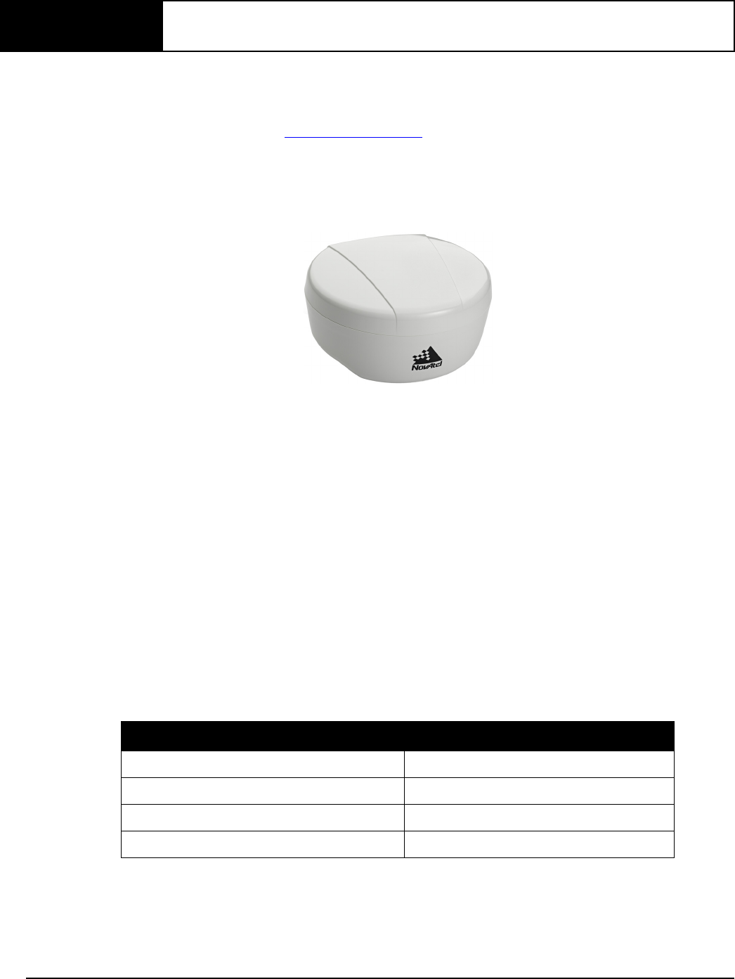
Once properly powered, the SMART6 begins operating as a fully functional GNSS system. Figure 1,
SMART6 Receiver shows the SMART6 without connecting cables.
Figure 1: SMART6 Receiver
1.1 Features and Models
The main features of the SMART6 are:
• an enhanced high performance GNSS L1/L2 receiver
• a high performance GNSS L1/L2 antenna
• a CAN port
• three RS-232 COM ports or
two RS-232 COM ports and Bluetooth
• three LED status indicators
• a water and dust tight enclosure
• Bluetooth wireless technology (optional)
• tilt compensation (optional)
The SMART6 is available in several different firmware models whose configurations may include other
additional features. Some possible configurations can be seen in Table 1, SMART6 Models.
Table 1: SMART6 Models
NovAtel Part Number Description
01019123 SMART6
01019125 SMART6 with Tilt
01019121 SMART6 with Bluetooth
01019127 SMART6 with Bluetooth and Tilt

Introduction Chapter 1
SMART6 User Manual Rev 0B 12
Contact NovAtel Sales at www.novatel.com/where-to-buy/contact-us for information regarding available
models, upgrading a model to increase feature/functionality or go to www.novatel.com/support/firmware-
software-and-manuals/firmware-software-updates/ to obtain product updates. Refer to Chapter 4, NovAtel
Firmware and Software on page 32 for details.
Refer to the OEM6 Installation and Operation Manual for detailed information on receiver
communications and operation.
SMART6 User Manual Rev 0B 13
Chapter 2 Installation and Setup
2.1 Additional Equipment Required
In order for the SMART6 to perform optimally, the following additional equipment is required:
• A cable harness for communicating and powering the SMART6 (NovAtel cable harness
01018999 is available with three DB-9 connectors, four bare cables and a SMART6
connector) or similar
• A fused power supply (user supplied) (refer to Table 7, Recommended Fuse and Fuse
Holders on Page 51 for details)
• A computer (user supplied)
2.1.1 SMART6 Setup
Complete the following steps to connect and power the SMART6.
1. Mount the SMART6 on a secure, stable structure with an unobstructed view of the sky from horizon to
horizon (refer to Section 2.1.4 Mounting the SMART6 on page 17 for details).
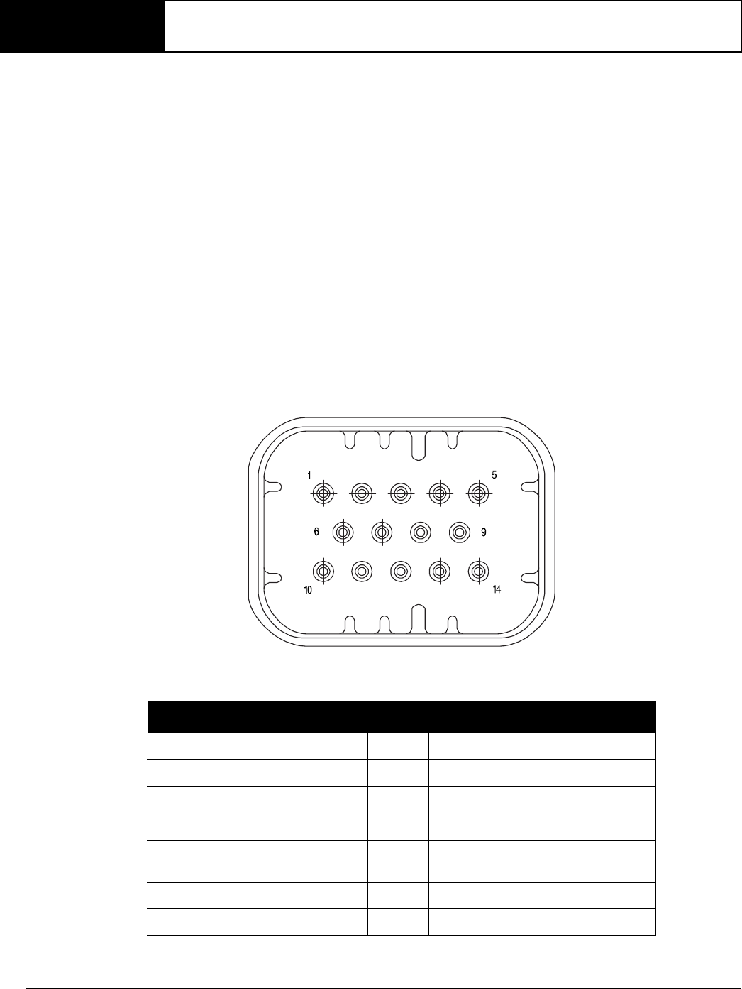
2. Connect the NovAtel interface cable, or custom wiring harness, to the COM and Power port on the back
of the SMART6, see Figure 2, SMART6 Connector.
Figure 2: SMART6 Connector
Table 2: SMART6 Connector Pin-Out
Pin Use Pin Use
1 COM1 TxD 8 COM3 TxDa
a. On Bluetooth models, COM3 is not available.
2 COM1 RxD 9 Power Negative/Return
3 COM2 TxD 10 ER_OUT (Emulated Radar Output)
4 COM2 RxD 11 MKI (Mark Input)
5 Signal Ground
(COM/MKI/PPS/ER)
12 PPS (Pulse Per Second) Output
6CAN+ 13COM3 RxD
a
7 CAN- 14 Power Positive/Source
Installation and Setup Chapter 2
SMART6 User Manual Rev 0B 14
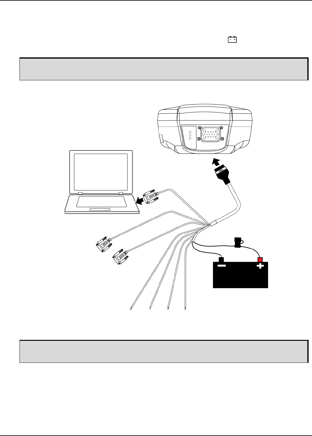
3. Connect the NovAtel cable or custom wiring harness to a DB-9 serial port on a computer or other data
storage device.
4. Connect the NovAtel cable or custom wiring harness to the power supply and turn on the power supply to
the SMART6 (the SMART6 cable is also a power cable). The power LED on the receiver glows red
when the SMART6 is properly powered.
Figure 3: Simplified SMART6 Setup
Fuse/holder recommendations can be found in Table 7, Recommended Fuse and Fuse Holders
on Page 51.
Minimum conductor size for all wiring is 0.5 mm/20 AWG. NovAtel recommends tying to ground
any floating input lines.
COM
COM
MKI PPS CAN
User supplied
5A fast blow fuse
COM
ER_OUT
Tyco 14-pin
Connector
Installation and Setup Chapter 2
SMART6 User Manual Rev 0B 15
2.1.2 Power Supply Requirements
The SMART6 requires +8 to +36 VDC input power (refer to SMART6 Specifications on page 47 for additional
power supply specifications).
The SMART6 cable provides power in (BATT+) and power ground (BATT-) bare wires for connecting the
SMART6 to a vehicular power system (or equivalent).
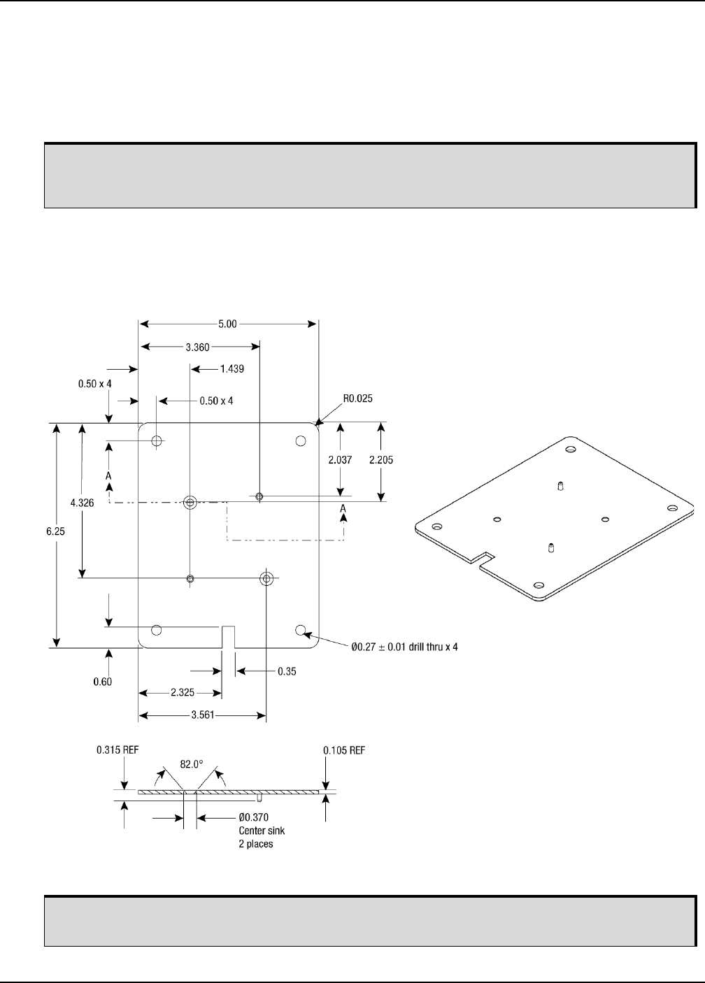
2.1.3 Mounting Plate
Two mounting plates are available to facilitate mounting the receiver: a surface mounting plate and a pole
mounting plate.
Figure 4: SMART6 Surface Mounting Plate
The SMART6 power source must be protected by a 5 A Fast Blow Fuse or damage to wiring
may result (not covered by warranty). Refer to SMART6 Connector and Cable Requirements on
page 50).
To install the mounting plate, use the adhesive tape or the mounting holes at each corner of the
plate.
Dimensions are in inches.
Installation and Setup Chapter 2
SMART6 User Manual Rev 0B 16
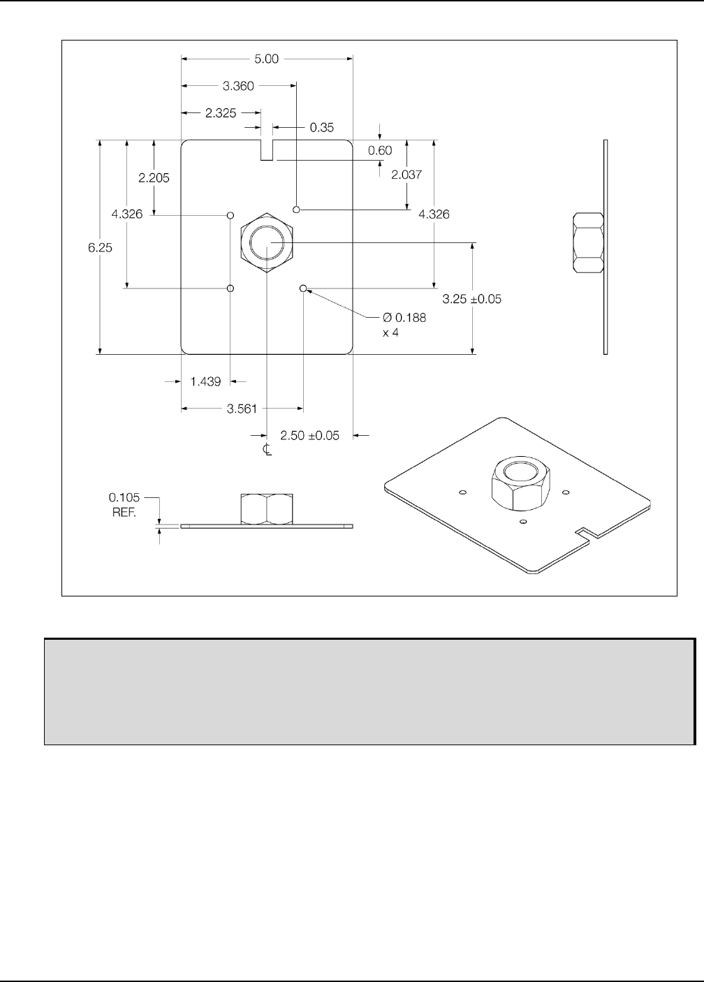
Figure 3: SMART6 Pole Mounting Plate
To install the pole mounting plate:
1. Use four M4 screws to connect the mounting plate to the SMART6.
2. Screw the mounting plate onto a mount, such as a range pole, tribrach, or tripod, with a 1" x
14 thread.
A 5/8” to 1” bushing adaptor is available (part number 12023275).
All dimensions are in inches
Installation and Setup Chapter 2
SMART6 User Manual Rev 0B 17
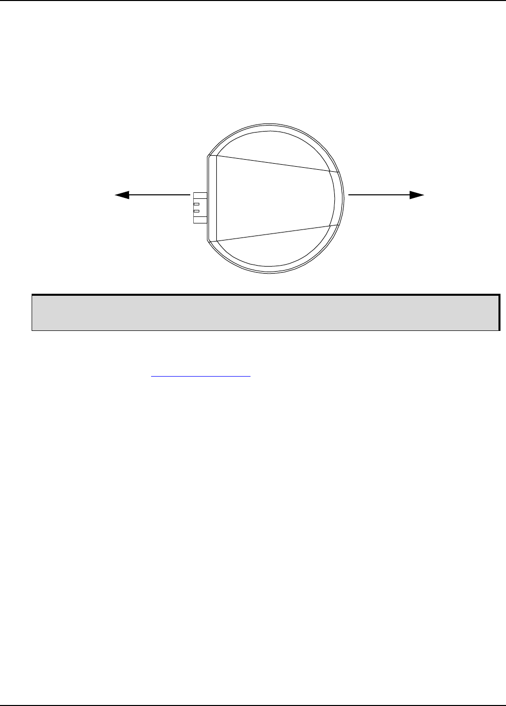
2.1.4 Mounting the SMART6
Mount the SMART6 on a secure, stable structure capable of safe operation in the specific environment.
• If installing on a vehicle, mount the SMART6 on the vehicle roof, ideally close to the pivot
point of the vehicle. The SMART6 must be mounted with the connector facing the rear of the
vehicle (see Figure 5, SMART6 Orientation).
Figure 5: SMART6 Orientation
• If installing in a stationary location, mount the SMART6 in a location that has a clear view of
the sky so that each satellite above the horizon can be tracked without obstruction. For more
information, refer to NovAtel’s GNSS Book.
2.1.5 Connecting Data Communications Equipment
To communicate with the receiver for sending commands and obtaining logs, a connection to data
communications equipment is required. Refer to Table 5, SMART6 Communication/Power Cable Pinouts on
Page 50 on for more information.
The SMART6 must be rigidly secured to the vehicle to avoid errors caused by vibration and
motion.
Orient toward the front
of vehicle
Route cable toward
back of vehicle

Installation and Setup Chapter 2
SMART6 User Manual Rev 0B 18
2.2 Additional Features and Information
This section contains information on the additional features of the SMART6, which may affect the overall
design of the receiver system.
2.2.1 Status Indicators
LED indicators on the SMART6 provide the status of the receiver. The table below shows the meaning of the
LEDs.
Troubleshooting:
• If the power is on but the yellow LED does not flash within one minute, then no satellites are being
tracked. There may be excessive blockage or the SMART6 may be defective. Make sure the SMART6
has an unobstructed view of the sky. Try power cycling the SMART6.
• If the yellow LED is flashing but doesn’t progress to solid yellow within one minute, then insufficient
satellites are being tracked or the signal quality is poor and ephemeris data cannot be received.
Normally, four satellites are sufficient for a valid position as long as they are widely distributed in the sky.
If LED is stuck on blinking yellow, there may be excessive signal blockage or the SMART6 may be
defective. Make sure the SMART6 has an unobstructed view of the sky. Try power cycling the SMART6.
• If the yellow LED is on, but the green doesn’t turn on within five minutes than no SBAS or DGPS
positions are available. If you are using SBAS, make sure SBAS is available in your area and that the
SMART6 is configured to enable SBAS positions (SBASCONTROL ENABLE). For DGPS, make sure the
SMART6 is configured with the correct serial port parameters and to accept the DGPS protocol your area
is using and that your data modem is connected and working.
• The green LED blinks when SBAS is detected then it comes on solid when SBAS is enabled. The LED
will stay dark if SBAS is not detected.
2.2.2 MKI and PPS Strobes
The Mark Input (MKI) and Pulse Per Second (PPS) strobe provide status and synchronization signals. PPS is
a 3.3 V CMOS output; MKI is a 5 V logic tolerant input.
Pin-out information can be found on Table 5, SMART6 Communication/Power Cable Pinouts on page 50.
Table 3: SMART6 LED Status Indicators
Red Yellow Green
Condition
Off Off Off Power is not available. (Red indicator may also not be lit if a boot failure has
occurred.)
On Off Off Power is available but no satellites are being tracked yet.
On Flashing Off Tracking at least one satellite but not a valid position.
On On Off Position valid in basic autonomous mode.
On On Flashing SBAS tracking, but not enough data for enhanced solution.
On On On Position valid in an enhanced accuracy mode
(WAAS/EGNOS/MSAS/DGPS).
Flashing means that the LED is turning on and off at a 1 Hz rate - 0.5 seconds on and 0.5
seconds off.
Installation and Setup Chapter 2
SMART6 User Manual Rev 0B 19
2.2.3 Emulated Radar (ER)
The SMART6 outputs an emulated RADAR signal via the bare wires labeled ER GND and ER_OUT on the
SMART6 cable. See Table 5, SMART6 Communication/Power Cable Pinouts on page 50 for the pin-out
details of this cable.
The ER outputs a logic high of supply voltage minus 0.5 V minimum and logic low of 0.5 V maximum with a
rise and fall time of less than 1 ms. Its output references signal GND and provides logic low output until its
speed is greater than 1 km/Hr. ER can be configured to operate at one of three distinct frequencies (26.11,
28.12 or 36.11 Hz/km/Hr, with 26.11 Hz/km/Hr being the default value) and with an effective range from 1 km/
Hr to 55 km/Hr for near-horizontal applications. See Section B.7, RADARCFG Configure the ER Output on
page 62 for more information.
2.2.4 Controller Area Network (CAN)
The SMART6 supports the following NMEA2000 Parameter Group Messages (PGN):
• PGN 129029 GNSSPositionData (1 Hz)
• PGN 129025 GNSSPositionRapidUpdate (10 Hz)
• PGN 129026 COGandSOGRapidUpdate (10 Hz)
2.2.5 Tilt Compensation
The SMART6 Tilt Compensation feature corrects for errors in position caused by tilting of the vehicle.
To fully install and set up tilt compensation:
1. Mount the SMART6 on the vehicle.
2. Measure, set and save the height of the SMART6 from the ground.
3. Level the tilt sensor and save the data.
2.2.5.1 Physical Installation
The SMART6 must be mounted as close to the center of the vehicle as possible, as illustrated in Figure 6,
SMART6 Installation.
The CAN must be activated by entering the SETCANNAME command (refer to B.8
SETCANNAME Sets the CAN name fields on page 63). To have the CAN set up automatically
at subsequent start ups, also send the SAVECONFIG command.
Table 4: Available CAN Signals on the SMART6
CAN Pins
CAN+ Pin 6
CAN- Pin 7
Refer to Tilt Compensation on page 30 for a detailed description of the Tilt Compensation
feature.
Refer to $PMDT Configure Tilt Compensation on page 61 for height, level and update
commands.
Installation and Setup Chapter 2
SMART6 User Manual Rev 0B 20
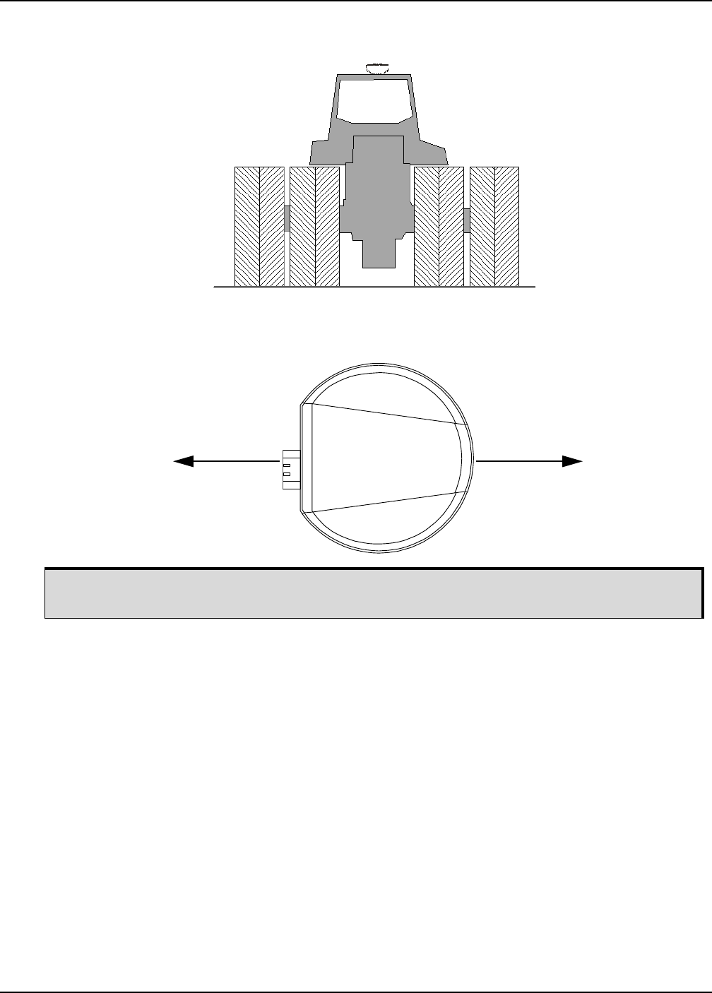
Figure 6: SMART6 Installation
The SMART6 must be mounted with the connector facing the rear of the vehicle, as shown in Figure 7,
SMART6 Orientation:
Figure 7: SMART6 Orientation
2.2.5.2 Height Measurement and Configuration
The height measurement should be made while the vehicle has the correct tire pressure and is parked on a
hard-packed and level surface. The measurement should be made from the ground to the bottom of the
SMART6 connector. The measurement accuracy should be within 1 to 2 inches (2.5 to 5.0 cm).
Once the measurement has been made (in feet and inches, or metres), refer to Section B.6,
$PMDT Configure Tilt Compensation on page 61 for instructions on how to set the height in the SMART6.
The height must be saved after the height command is sent. This must be done so the height data is saved
between power cycles. Instructions on sending the save command are outlined in Section B.6,
$PMDT Configure Tilt Compensation on page 61.
Note that changes in tire pressure over time can potentially cause errors in tilt compensation. This is because
the height of vehicle can vary with tire pressure.
The SMART6 is shipped from the factory with the height set to 0.0 metres.
2.2.5.3 Leveling the Tilt Sensor
The SMART6 must be rigidly secured to the vehicle to minimize errors due to vibration and
motion.
SMART6
Orient toward the front
of vehicle
Route cable toward
back of vehicle

Installation and Setup Chapter 2
SMART6 User Manual Rev 0B 21
The vehicle must be parked on flat ground when the level command is sent to the SMART6. Refer to
Section B.6, $PMDT Configure Tilt Compensation on page 61 for instructions on how to send the level
command.
After the tilt sensor has been leveled, the data must be saved to non-volatile memory using the save
command. Instructions on using the save command are outlined in Section B.6, $PMDT Configure Tilt
Compensation on page 61.

SMART6 User Manual Rev 0B 22
Chapter 3 Operation
Before operating the SMART6 for the first time, ensure the installation instructions in Chapter 2, Installation
and Setup were followed. It is assumed that a computer is used during initial operation and testing for greater
ease and versatility.
3.1 Communications with the Receiver
Communication with the receiver typically consists of issuing commands through the communication ports
from an external serial communications device. This could be either a terminal or computer connected
directly to the receiver serial port using a DB-9 connector on the SMART6 communication/power cable. If
using a radio, connect it to another DB-9 connector on the same communication/power cable by means of
the radio serial cable supplied with the radio. It is recommended that you become thoroughly familiar with the
commands and logs detailed in the OEM6 Family Firmware Reference Manual to ensure maximum utilization
of the receiver’s capabilities.
3.1.1 Serial Port Default Settings
The receiver communicates with the computer or terminal via an RS-232 serial port. For communication to
occur, both the receiver and the operator interface have to be configured properly. The receiver’s COM1,
COM2 and COM3 default port settings are as follows:
• 9600 bps, no parity, 8 data bits, 1 stop bit, no handshaking, echo off
To change the default settings, use the COM command. See Appendix B.3, COM Configure COM Port
starting on Page 54 for details.
The data transfer rate chosen determines how fast information is transmitted. For example, outputting a log
whose message byte count is 96. The default port settings allows 10 bits/byte (8 data bits + 1 stop bit + 1
framing bit). It therefore takes 960 bits per message. To get 10 messages per second, 9600 bps is required.
Also remember that even if the bps is set to 9600, the actual data transfer rate is lower and depends on the
number of satellites being tracked, data filters in use and idle time. It is suggested a margin is set when
choosing a data rate (115200 is recommended for most applications).
3.1.2 Communicating Using a Remote Terminal
One method of communicating with the receiver is through a remote terminal. The receiver is pre-wired to
allow proper RS-232 interface with the data terminal. To communicate with the terminal, the receiver only
requires the RX, TX and GND lines to be used. Request to Send (RTS)/Clear to Send (CTS) hardware
handshaking is not available. Ensure the terminal’s communications set up matches the receiver’s RS-232
protocol.
3.1.3 Communicating Using a Computer
A computer can be set up to emulate a remote terminal as well as provide the added flexibility of creating
multiple command batch files and data logging storage files. Any standard communications software
package, that emulates a terminal, can be used to establish bidirectional communications with the receiver.
For example, HyperTerminal or NovAtel’s Graphical User Interface (GUI) program NovAtel Connect™. All
data is sent as raw 8-bit binary or ASCII characters.
Although the receiver can operate at data transfer rates as low as 300 bps, this is not desirable.
For example, if several data logs are active (that is, a significant amount of information needs to
be transmitted every second) but the bit rate is set too low, data will overflow the serial port
buffers, causing a warning in the receiver status and loss of data.
Operation Chapter 3
SMART6 User Manual Rev 0B 23
3.2 Getting Started
3.2.1 Starting the Receiver
When first powered, the SMART6 undergoes a complete self-test. The results of this test can be viewed by
connecting to the receiver and requesting the RXSTATUS log. Refer to the OEM6 Family Firmware
Reference manual for details.
If a persistent error develops, contact your local NovAtel dealer first. If the problem remains unresolved,
contact NovAtel directly through any of the methods listed in the Customer Service section on page 9.
3.2.2 Communicating with the Receiver Using NovAtel Connect
NovAtel Connect is a Windows based GUI used to access the receiver's many features. Convert is a utility
that converts between file formats and strips unwanted records for data file compilation. Both are included in
the NovAtel Connect PC Utilities bundle available from: www.novatel.com/support/firmware-software-and-
manuals/firmware-software-updates/.
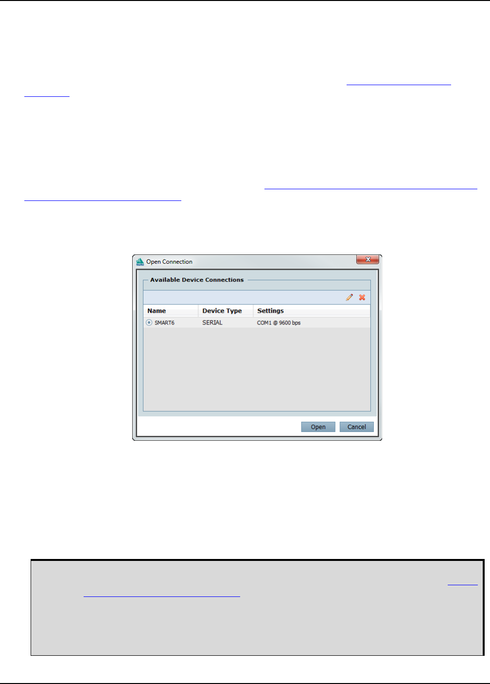
Launch the NovAtel Connect program and select Device | Open Connect from its main menu. The Open
Connection window appears.
Figure 8: Open Connection Window
Refer to the NovAtel Connect help file or press F1 while the cursor is in a NovAtel Connect window. Ensure
the Console and ASCII Messages windows are open by selecting them from the View menu.
When the receiver is first turned on, no data is transmitted from the COM ports except for the port prompt.
The console window displays a port name:
[COM1] if connected to COM1 port
[COM2] if connected to COM2 port
[COM3] if connected to COM3 port or through Bluetooth
Any of the above prompts indicate the receiver is ready and waiting for command input.
1. You may also have to wait for output from receiver self-tests. For example, on start-up, the
SMART6 is set to log the RXSTATUSEVENTA log ONNEW on all ports. Refer to the OEM6
Family Firmware Reference Manual for more details.
2. If NovAtel Connect is unable to locate the SMART6, try using a different COM port to
communicate to the receiver. Once communication has been established, issue the FRESET
STANDARD command. You should now be able to use the original communication port
again.

Operation Chapter 3
SMART6 User Manual Rev 0B 24
Commands are typed at the interfacing computing device’s keypad and executed after issuing a carriage
return command which is usually the same as pressing the <Enter> key.
An example of a response to an input command is the FIX POSITION command. It can be as:
[COM2] FIX POSITION 51.11635 -114.0383 1048.2 [Carriage Return]
<OK
where [COM2] is the port prompt, followed by the command entered and [Carriage Return] is a prompt to
press the <Enter> key.
The example above illustrates the command input to the base receiver’s COM2 port, which sets the position
of the base station receiver for differential operation. Confirmation that the command was actually accepted is
the appearance of <OK.
If a command is entered incorrectly, the receiver responds with:
<Invalid Message ID (or a more detailed message)
3.3 Transmitting and Receiving Corrections
RTK or DGPS corrections can be transmitted from a base station to a rover station to improve position
accuracy. The base station is the GNSS receiver, which is acting as the stationary reference. It has a known
position and transmits correction messages to the rover station. The rover station is the GNSS receiver which
does not know its exact position and can be sent correction messages from a base station to calculate
differential GNSS positions. The SMART6 can be used as a base receiver to transmit RTK or DGPS
corrections or a rover to receive the same corrections. An example of a differential setup is given in Figure 9,
Basic Differential Setup on page 25.
Ensure the computer’s Control Panel Power Settings are not set to Hibernate or Standby
modes. Data is lost if one of these modes occurs during a logging session.
Operation Chapter 3
SMART6 User Manual Rev 0B 25
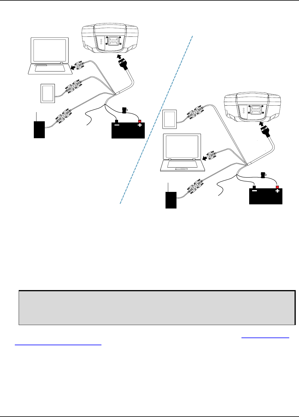
Figure 9: Basic Differential Setup
Reference Description
1 SMART6 receiver
2 User supplied 5 A fast blow fuse
3 User supplied power supply, for example a battery
4 User supplied device to COM1
5 User supplied device to COM2
6 User supplied device to COM3
7 User supplied cable or NovAtel 01018999 Communication/Power cable
System biases can introduce errors, refer to our GNSS Book found on our Web site at www.novatel.com/
support/knowledge-and-learning/ for more information. In most cases, a data link between the base station
and rover station (two NovAtel receivers) is required to receive corrections. SBAS corrections can be
accomplished with one receiver and are exceptions to the base/rover concept. Generally, a link capable of
data throughput at a rate of 9600 bits per second and less than 4.0 s latency is recommended.
Once the base and rover are set up, configure them as shown in the configuration examples that follow in
Section 3.3.1, Base Station Configuration on page 26 and Section 3.3.2, Rover Station Configuration on
page 27.
The configuration shown in Figure 9, Basic Differential Setup is valid for SMART6 receivers
without optional Bluetooth.
For a SMART6 receiver with Bluetooth, two of the serial devices connect through COM1 and
COM2 and the other device must connect through Bluetooth.
Rover Base
2
3
4
5
6
1
2
3
5
COM2
COM3 COM1
COM2
COM1
COM3
4
1
6
7
7

Operation Chapter 3
SMART6 User Manual Rev 0B 26
3.3.1 Base Station Configuration
At the base station, enter the following commands:
COM [port] bps [parity[databits[stopbits[handshake[echo[break]]]]]]
interfacemode port rx_type tx_type [responses]
fix position latitude longitude height
log port message [trigger [period]]
Examples of these commands include the following:
RTCA com com2 9600 N 8 1 N off
interfacemode com2 none rtca off
fix position 51.11358042 -114.04358013 1059.4105
log com2 rtcaobs ontime 1
log com2 rtcaref ontime 10
log com2 rtca1 ontime 5 (optional for RTK)
log com2 rtcaephem ontime 10 1 (optional)
RTCM com com2 9600 N 8 1 N off
interfacemode com2 none rtcm off
fix position 51.11358042 -114.04358013 1059.4105
log com2 rtcm3 ontime 10 (required for RTK)
log com2 rtcm22 ontime 10 1 (optional)
log com2 rtcm1819 ontime 1
log com2 rtcm1 ontime 5
RTCMV3 com com2 9600 N 8 1 N off
interfacemode com2 none rtcmv3 off
fix position 51.11358042 -114.04358013 1059.4105
log com2 rtcm1006 ontime 10
log com2 rtcm1003 ontime 1
CMR+ com com2 9600 N 8 1 N off
interfacemode com2 none cmr off
fix position 51.11358042 -114.04358013 1059.4105
log com2 cmrobs ontime 1
log com2 cmrplus ontime 1 (Important to use ontime 1 with cmrplus)
CMR com com2 9600 N 8 1 N off
interfacemode com2 none cmr off
fix position 51.11358042 -114.04358013 1059.4105
log com2 cmrobs ontime 1
log com2 cmrref ontime 10
log com2 cmrdesc ontime 10 1

Operation Chapter 3
SMART6 User Manual Rev 0B 27
3.3.2 Rover Station Configuration
At the rover station, enter:
COM [port] bps [parity[databits[stopbits[handshake[echo[break]]]]]]
interfacemode port rx_type tx_type [responses]
For example:
RTCA interfacemode com2 rtca none off
RTCM interfacemode com2 rtcm none off
RTCMV3 interfacemode com2 rtcmv3 none off
CMR+ interfacemode com2 cmr none off
CMR interfacemode com2 cmr none off (same as CMR+)
3.3.3 GPS + GLONASS Base and Rover Configuration
This section shows how to set up a base and rover OEM6 GPS + GLONASS enabled receivers for GPS +
GLONASS RTK operation:
Base Station:
fix position lat lon hgt (enter your own lat, lon, and hgt values)
com com2 9600 N 8 1 N off
interfacemode com2 none rtca off
log com2 rtcaref ontime 10
log com2 rtcaobs2 ontime 1
log com2 rtca1 ontime 5 (optional, enable code-DGPS coverage)
saveconfig (optional, save configuration to non-volatile memory)
Rover Station:
com com2 9600 N 8 1 N off
interfacemode com2 rtca none off
log com1 bestposa ontime 1 (optional, view position information)
saveconfig (optional, save configuration to non-volatile memory)

Operation Chapter 3
SMART6 User Manual Rev 0B 28
3.3.4 Configuration Notes
For compatibility with other GNSS receivers and to minimize message size, it is recommended using the
standard form of RTCA, RTCM, RTCMV3 or CMR corrections as shown in the base and rover examples
above. This requires using the INTERFACEMODE command to dedicate one direction of a serial port to only
that message type. When the INTERFACEMODE command is used to change the mode from the default,
NOVATEL, you can no longer use NovAtel format messages.
To mix NovAtel format messages and RTCA, RTCM, RTCMV3 or CMR messages on the same port, leave
the INTERFACEMODE set to NOVATEL and log out variants of the standard correction messages with a
NovAtel header. ASCII or binary variants can be requested by simply appending an "A" or "B" to the standard
message name. For example on the base station:
interfacemode com2 novatel novatel
fix position 51.11358042 -114.04358013 1059.4105
log com2 rtcm1b ontime 2
Using the receiver in this mode consumes more CPU bandwidth than using the native differential messages
as shown in Section 3.3.1, Base Station Configuration on page 26.
At the rover station, leave the INTERFACEMODE default settings (interfacemode com2 novatel novatel). The
rover receiver recognizes the default and uses the corrections it receives with a NovAtel header.
The PSRDIFFSOURCE and RTKSOURCE commands set the station ID values which identify the base stations
from which to accept pseudorange or RTK corrections respectively. These are useful commands when the
rover station is receiving corrections from multiple base stations. Refer to NovAtel’s GNSS Book for more
information on SBAS, available from www.novatel.com.
All PSRDIFFSOURCE entries fall back to SBAS (even NONE) for backwards compatibility (assuming SBAS
was enabled).
At the base station it is also possible to log out the contents of the standard corrections in a form that is easier
to read or process. These larger variants have the correction fields broken out into standard types within the
log, rather than compressed into bit fields. This can be useful to modify the format of the corrections for a
non-standard application or to look at the corrections for system debugging purposes. These variants have
"DATA" as part of their names (for example, RTCADATA1, RTCMDATA1, CMRDATAOBS and more). Refer
also to the OEM6 Family Firmware Reference Manual detailed descriptions of the various message formats.
Information on how to send multiple commands and log requests using DOS or Windows can be found on our
web site at www.novatel.com/support/knowledgedb.htm.

Operation Chapter 3
SMART6 User Manual Rev 0B 29
3.4 GLIDE
SMART6 contains NovAtel’s GLIDE which is a positioning algorithm for single-frequency GPS and GPS/
GLONASS applications. GLIDE produces a smooth position output tuned for applications where time relative
accuracy (pass-to-pass) is more important than absolute accuracy. Because of this, it is well suited for
agricultural applications.
Multipath signals tend to induce time varying biases and increase the measurement noise on the L1/L2
pseudorange measurements. Carrier phase measurements are much less susceptible to the effects of
multipath. The GLIDE algorithm fuses the information from the L1 code and the L1 phase measurements into
a Position Time Velocity (PVT) solution.
GLIDE includes settings for a dynamic mode, a static mode and an “auto” mode, where the filtering
parameters are automatically adjusted as vehicle velocity varies between stationary and dynamic states.
3.4.1 Dual-Frequency GLIDE
NovAtel’s dual-frequency GLIDE technology adds to the superior pass-to-pass performance provided by
single-frequency GLIDE. Dual-frequency GLIDE is ideal for agricultural and machine guidance applications
where relative positioning is critical. Using GLIDE significantly reduces the variation in position errors to less
than 1 cm from one epoch to the next. Dual-frequency GLIDE improves the absolute accuracy of the GLIDE
position and creates a robust solution resistant to the effects of high ionospheric activity. GLIDE works in all
code positioning modes, including single point, DGNSS and SBAS.
Refer to the NovAtel white papers at www.novatel.com/support/knowledge-and-learning/published-papers-
and-documents/white-papers/ for more information on GLIDE. Also refer to application note “APN-038
Pseudorange/Delta-Phase (PDP) and GL1DE Filters” at www.novatel.com/support/knowledge-and-learning/
published-papers-and-documents/application-notes/.
3.5 Emulated Radar (ER)
A typical radar sensor emits radio beams that bounce off the ground and computes ground speed based on
the speed at which objects are passing in front of the sensor. The output of the sensor is a digital pulse, the
frequency of which is proportional to the vehicle’s ground speed. This is often used in agricultural applications
such as planting and spraying. The SMART6 eliminates the need for separate ground-sensing radar
equipment by converting the GPS-derived velocity to proportional frequency output. The following emulated
radar signal parameters can be configured by the customer:
• Frequency Step: Specifies how the frequency output relates to the vehicle speed.
• Signal Update Rate: Specifies how often the frequency output is updated to match the vehicle speed.
• Response Mode: Specifies how quickly changes in velocity are reflected in the frequency output.
Setting a slower response mode reduces spikes (noise) in the velocity but increases latency.
Setting a higher response mode reduces latency, but may result in noisier frequency output.
Refer to RADARCFG Configure the ER Output on page 62 for more detailed information.
After it is configured using the RADARCFG command, Emulated Radar (ER) pulses are output through the
SMART6 cables (see Table 5, SMART6 Communication/Power Cable Pinouts on page 50) and the
RADARSIGNAL log (see RADARSIGNAL ER Signal and Position Information on page 66).
Operation Chapter 3
SMART6 User Manual Rev 0B 30
3.6 Tilt Compensation
The SMART6 Tilt Compensation feature corrects for errors in position caused by tilting of the vehicle. The
SMART6 senses the vehicle’s roll angle and, with the user-entered “height above ground”, compensates the
position output to give the position under the vehicle rather than at the antenna.
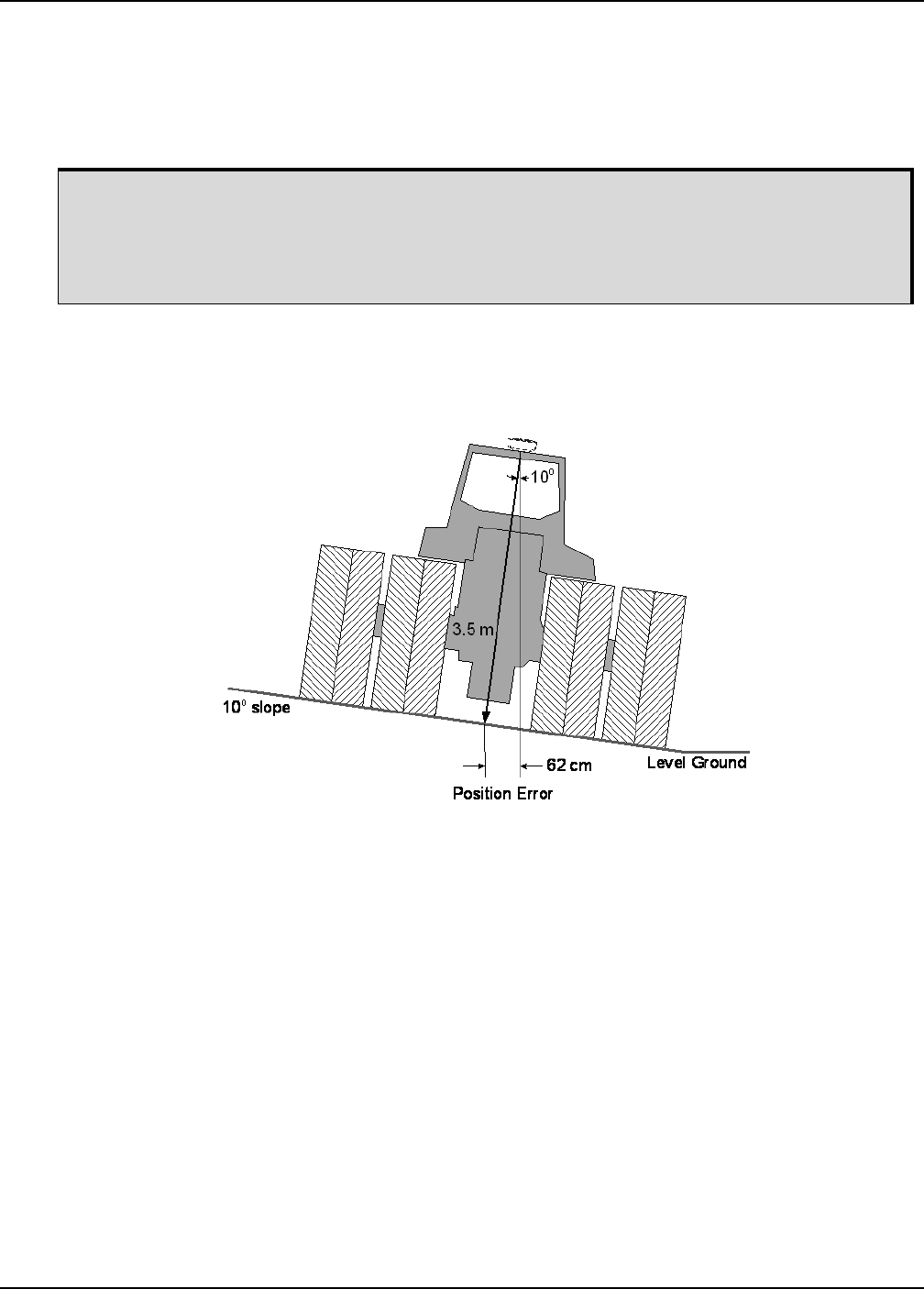
As shown in Figure 10, SMART6 Tilt Compensation, if an agricultural implement is operating on sloped
terrain, the position will be in error by an amount proportional to the tilt angle.
Figure 10: SMART6 Tilt Compensation
If tilt compensation is enabled, the SMART6 determines the tilt and corrects the position data before it is
forwarded to the user equipment. In the above example, the tilt is 10 degrees, and the position correction that
needs to be applied is 62 cm.
The BESTPOS, BESTXYZ and all NMEA GPGGA logs will provide tilt-compensated position logs.
Information about installation and setup can be found in:
•Tilt Compensation on page 19
Information about tilt-compensation commands can be found in:
•$PMDT Configure Tilt Compensation on page 61
SMART6

Operation Chapter 3
SMART6 User Manual Rev 0B 31
3.7 Recommended Configuration
The following command is recommended to enable CAN:
setcanname 305 2 0 0 23 0 0 28 can2
The following command is recommended to enable SBAS (WAAS/GNOS/MSAS) corrections:
sbascontrol enable
The following commands are recommended to enable GLIDE:
pdpfilter enable
pdpmode relative auto
NovAtel has registered manufactured ID code 305 with J1939. When complete, configuration can be saved
with the SAVECONFIG command. For more information about these commands, refer to the OEM6 Family
Firmware Reference Manual, available at www.novatel.com/support/firmware-software-and-manuals/
product-manuals-and-doc-updates/.

SMART6 User Manual Rev 0B 32
Chapter 4 NovAtel Firmware and Software
Download the most recent versions of the NovAtel firmware and receiver software from the NovAtel website
at www.novatel.com Support/Firmware/Software and Manuals.
OEM6 Firmware and Software
NovAtel Connect PC Utilities Software Bundle
Bundled PC Utilities software includes:
• NovAtel Connect (a GUI interface)
• Connection Import (improves connection profiles)
• Convert (converts receiver data logs into different formats)
• USB Drivers and Window Signing
Firmware and Software included
• SoftLoad firmware
• WinLoad software utility
4.1 Firmware Updates and Model Upgrades
A local NovAtel dealer can provide all the information needed to upgrade or update a receiver. Refer to
www.novatel.com/where-to-buy for contact information or contact sales@novatel.com or
support@novatel.com directly.
4.1.1 Firmware Updates
Firmware updates are firmware releases that include fixes and enhancements to the receiver functionality.
Firmware updates are released on the NovAtel web site as they become available. New firmware must be
loaded into the receiver through one of the COM ports. Once loaded, the receiver reboots and begins
operating with the new firmware.
Refer to Section 4.3.1, Transferring Firmware Files on page 34 for descriptions of the Update
and OEM versions.
The NovAtel Connect PC Utilities bundle can be download from our web site: www.novatel.com/
support/firmware-software-and-manuals/firmware-software-updates/novatel-connect/
WinLoad and SoftLoad instructions follow.
Direct access to a serial COM port on the SMART6 receiver is required.
NovAtel Firmware and Software Chapter 4
SMART6 User Manual Rev 0B 33
4.1.2 Model Upgrades
Model upgrades enable purchased receiver features.
Contact a local NovAtel dealer to assist in selecting the upgrade options that best suit your GNSS needs at
www.novatel.com/where-to-buy. Contact NovAtel Customer Support www.novatel.com/support or NovAtel
Sales to request a temporary upgrade authorization code for trial purposes.
The receiver stores the firmware in Non-Volatile Memory (NVM), which allows model upgrades to be
performed without returning the receiver to the dealer. Model upgrades can be applied to the receiver with an
authorization code and the AUTH command.
4.2 Authorization Code
An authorization code, commonly known as an auth-code, is required to upgrade and possibly update an
OEM6 family receiver. Auth-codes are obtained by contacting NovAtel Customer Support. Upon contact,
NovAtel Customer Support requires:
• the receiver model number
• the receiver serial number
• the receiver firmware version
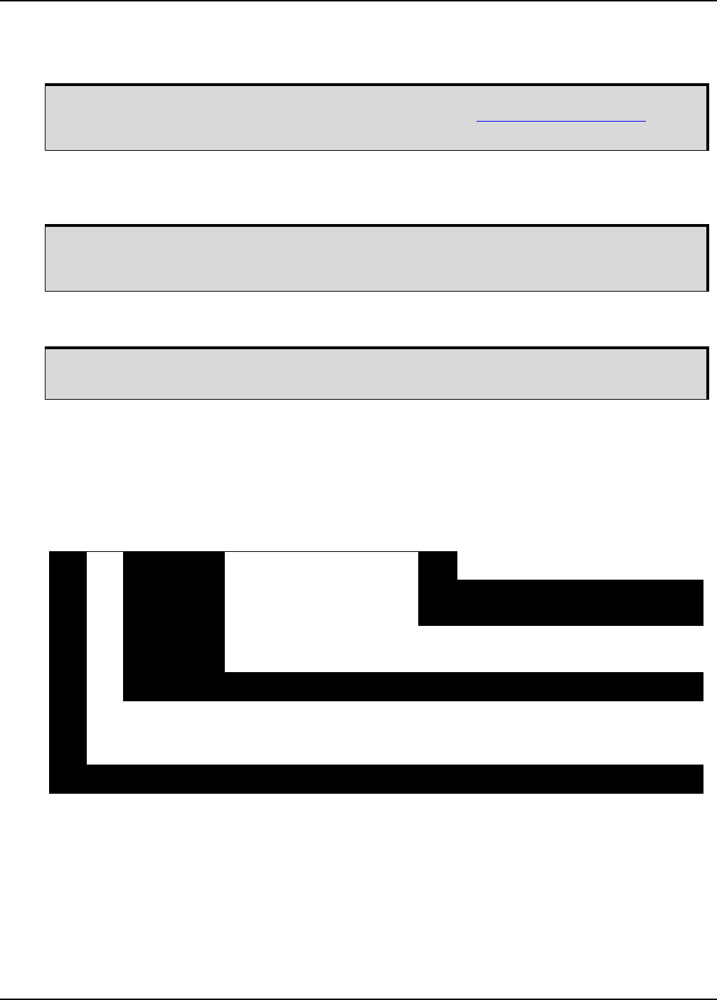
Enter the LOG VERSION command to determine the receiver model, serial number and firmware version.
Example:
After determining the appropriate model and firmware version the authorization code (auth-code) is issued.
The auth-code is required to unlock the features on the new model type.
To upgrade to a new model with the same firmware version, use the AUTH command with the issued auth-
code (if required), as outlined in Upgrading Using the AUTH Command.
To upgrade to a new model with a higher firmware version, the new firmware .shex file needs to be loaded
into the OEM6 receiver using the WinLoad utility program. WinLoad and the firmware .shex files can be
found at www.novatel.com/Support/Firmware/Software and Manuals/Product Updates. Refer to
Section 4.3,
Updating or Upgrading Using the WinLoad Utility
on page 34 for use instructions.
Firmware version OEM060200RN0000 (also known as firmware version 6.200) and later contain the
Firmware Signature feature. This firmware feature removes the authorization code dependency on the
firmware version and eliminates the need to obtain an auth-code when downloading the latest version of
signed firmware.
If updating from a version before 6.200 to a signed 6.200 version, an authorization code is required. The
receiver must have boot version code 6.100 or later for signed firmware to work.
In version OEM060200RN0000, the receiver serial number and the software model are built into the
signature in the firmware file. Once the 6.200 signed firmware is installed with a signature auth-code, future
firmware updates no longer require a new unique auth-code.
An authorization code is still required if the software model changes for temporary trial
upgrades or purchased permanent upgrades.
GPSCARD “D2LR0RTTRA” “BFN11230026” “OEM615-1.00” “OEM060200RN0000”
PRODUCT
FIRMWARE
RELEASE
INDICATOR
FAMILY
NUMBER
SERIALMODEL
NUMBER NUMBER
FIRMWARE
VERSION
ENTER

NovAtel Firmware and Software Chapter 4
SMART6 User Manual Rev 0B 34
The new download package includes a signed firmware file type that uses an extension designated as
“.shex” (example OEM060200RN0000.shex), as well as the latest Winload utility and What’s New file
containing firmware update change details.
4.3 Updating or Upgrading Using the WinLoad Utility
WinLoad is the simplest and most common way to update or upgrade an OEM6 receiver.
4.3.1 Transferring Firmware Files
To proceed with an update or possibly an upgrade, obtain the latest version of firmware from the NovAtel
website at www.novatel.com/support/firmware-software-and-manuals/firmware-software-updates/oem6-
family/.
Types of Firmware Files
•OEM Version - NovAtel Customer Service may generate and provide the required authorization
code. Authorization codes are obtained by contacting support@novatel.com or at www.novatel.com/
Support/.
The OEM version is named OEMXXXX.EXE, where XXXX is the firmware version.
For convenience, copy the update file to a GNSS sub-directory (for example, C:\GNSS\LOADER).
If the firmware update file is password protected, NovAtel Customer Support provides the required password.
After copying the file to a computer, perform the following steps to extract the files:
Syntax: [filename] [password] (if required)
where filename is the name of the compressed file (but not including the .EXE extension) and password if the
password is required for extraction.
Example: OEM060200RN0000.shex
In the above example, a window appears asking for a password.
The self-extracting archive produces the following files:
winload.exe WinLoad utility program
howto.txt Instructions on how to use the WinLoad utility
whatsnew.rtf Information on the changes made in the firmware since the last revision
x..x.shex Firmware version upgrade file, where x..x defines the product name and release (e.g.,
OEM060000RN0000.shex)
The files are extracted to unzip/program files/NovAtel Inc/x.xxx Full Update Disk, where x.xxx is the firmware
version.
Prior to firmware version OEM060200RN0000, authorization codes depended on the software
model, the firmware version and the serial number of the receiver. The authorization code
changed if any of the three items changed. This is no longer the case.
NovAtel has an online video tutorial that explains firmware uploading at: www.novatel.com/
support/knowledge-and-learning/video-tutorials-and-tech-presentations/.
NovAtel Firmware and Software Chapter 4
SMART6 User Manual Rev 0B 35
4.3.2 Using the WinLoad Utility
If opening WinLoad for the first time, ensure the file and communications settings are correct.
Open a File to Download
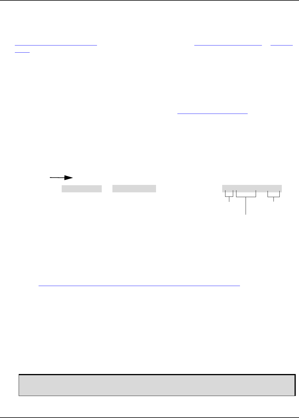
Select File |Open. Navigate to the file to open (Figure 11).
Figure 11: WinLoad’s Open Window
When a file is selected, the filename appears in the main WinLoad display area and in the title bar (Figure
12).
Figure 12: Open File in WinLoad
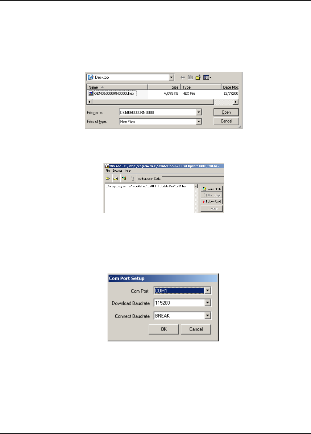
Communications Settings
To set the communications port and baud rate, select Settings | COM Settings. Choose the computer port to
use from the Com Port drop down list and the baud rate from the Download Baudrate drop down list. Set the
baud rate as high as possible (the default of 115200 is preferred if a higher baud rate is not available).
Figure 13: COM Port Setup
Downloading Firmware
1. Select the file to download according to Open a File to Download on Page 35.
2. Ensure the file path and name are displayed in main display area (see Figure 12, Open File in WinLoad
on page 35).
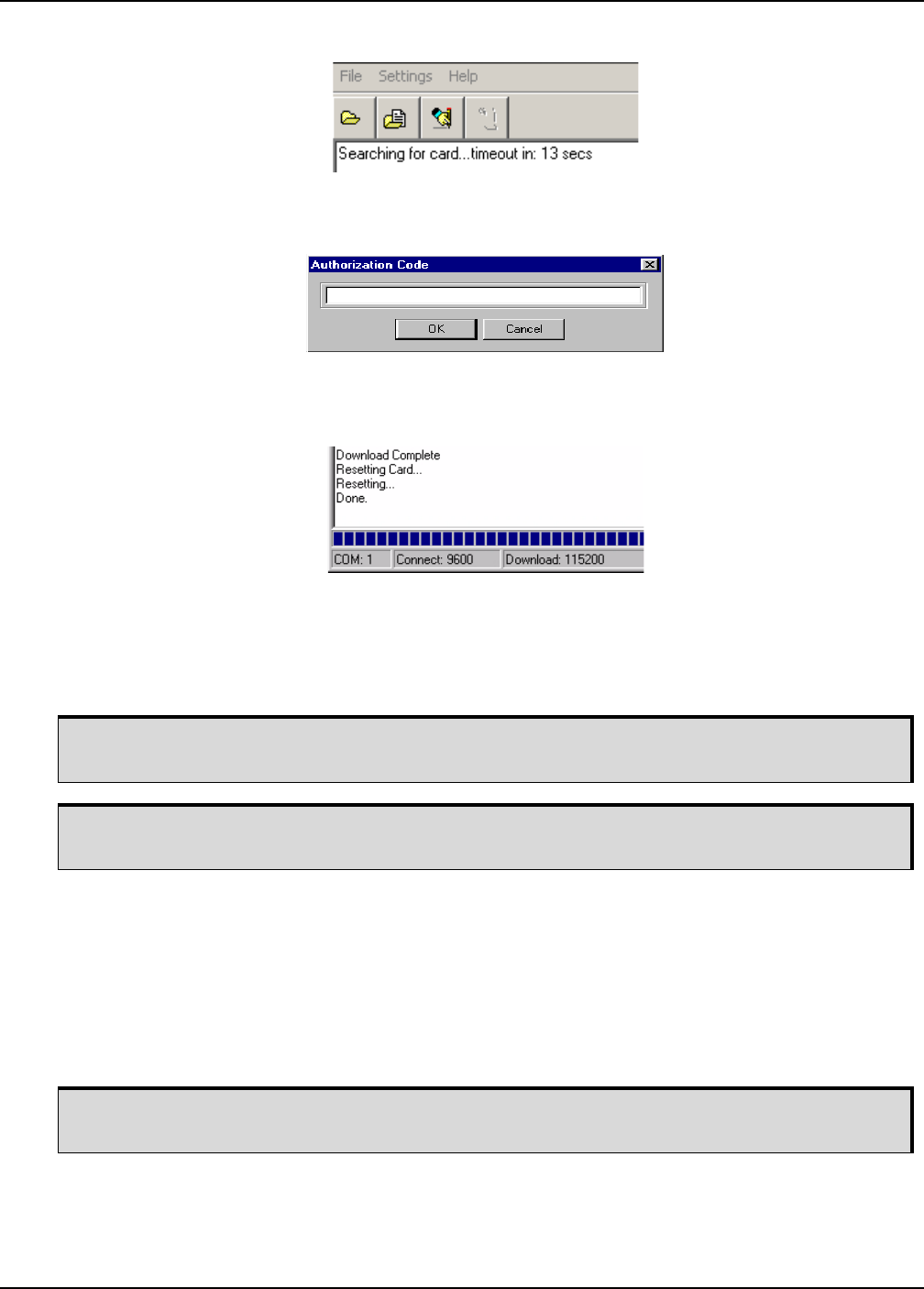
3. Click Write Flash to download the firmware.
4. When Searching for card appears in the main display, power cycle the receiver.
NovAtel Firmware and Software Chapter 4
SMART6 User Manual Rev 0B 36
Figure 14: Searching for Card
5. If the Authorization Code window appears, enter the auth-code and click OK. See Section 4.2, Authoriza-
tion Code on page 33 for further information about the Authorization Code.
Figure 15: Authorization Code Window
6. The receiver finishes the download and then resets. The process is complete when Done appears in the
main display area.
Figure 16: Upgrade Process Complete
7. Close WinLoad.
4.4 Updating using SoftLoad Commands
To use Softload to update an OEM6 family receiver.
1. Open a connection to any port on the receiver.
2. Request the SOFTLOADSTATUSA log using the following command:
LOG SOFTLOADSTATUSA ONCHANGED
3. Initialize SoftLoad with a SOFTLOADRESET command. This command stops all tracking on the receiver
to ensure sufficient memory is available for the loading process. A RXSTATUSEVENTA log reports a
SoftLoad In Progress status.
4. Open the *.shex firmware file.
Use SoftLoad if automated loading is required or the platform used to communicate with the
receiver is not supported by WinLoad.
Refer to Types of Firmware Files on page 34 for details on updating versus upgrading.
If using NovAtel Connect, close all windows before using the SOFTLOADSREC command to
avoid failure. Only the Console and ASCII Message windows may remain open.
NovAtel Firmware and Software Chapter 4
SMART6 User Manual Rev 0B 37
5. Send each line of the *.shex file to the receiver in a SOFTLOADSREC command. The S-Records must be
enclosed by quotation marks:
SOFTLOADSREC "<S-RECORD>"
6. Send the SOFTLOADCOMMIT command.
7. During the loading process, SOFTLOADSTATUSA logs report the load status. Wait for the SOFTLOAD-
STATUSA to indicate loading is complete.
8. Reset the receiver by entering RESET or FRESET command or power cycling.
9. Once the receiver resets, the new version of firmware is active.
4.4.1 Working with S-Records
• Records beginning with S0, S5 and S7 should be passed to the receiver directly using the
SOFTLOADSREC command. These records contain meta data about the firmware image.
• Records beginning with S3 form the actual firmware image and can be converted to SOFTLOADDATA
binary commands. Aside from the header, each pair of characters forms the ASCII representation of
binary byte. The format is as follows:
• Multiple S3 records can be packaged into a single SOFTLOADDATA command as long as the data from
one S3 record follows immediately after the previous record, up to a maximum of 4096 bytes of data.
That is, the address must equal the previous address plus the previous data length. The "offset" field
remains the address of the first S3 record and the "data" and "data length" are updated to include the
new data.
• The shex file data may contain many gaps and jumps. For example, in most NovAtel shex files data for
address 0x000_00000 is stored near the very end of the file.
To significantly decrease data transfer time, NovAtel recommends creating a batch file to
automatically send each line of SOFTLOADSREC. Contact NovAtel Customer Support for
assistance creating SoftLoad batch files.
Signature auth-codes are maintained internally by the receiver and do not need to be r
e-entered. Refer to Section 4.2, Authorization Code on page 33 for details on obtaining any
auth-code.
The SoftLoad process can be cancelled safely at any time during the process using the RESET
command.
S3 LL AAAAAAAA DDDDDDDD...DDDDDDDD CC
Check Sum. One's compliment of all other
bytes
Little Endian Data. These bytes are copied into the "data" field of the
SOFTLOADDATA command
4 - Byte Address. Set this as the value of "offset" in the SOFTLOADDATA command
Length.This is the hexadecimal number of character pairs to follow in the record. This value
minus 4 bytes for the address and 1 byte for the check sum is copied into the "data length" field
of the SOFTLOADDATA command
Header

NovAtel Firmware and Software Chapter 4
SMART6 User Manual Rev 0B 38
4.5 Upgrading Using the AUTH Command
The AUTH command authorizes the enabling (unlocking) of model features. The AUTH command is used to
upgrade a new OEM6 family model, available with the same firmware version as the current model. This
command only functions with a valid auth-code assigned by NovAtel Customer Support.
The upgrade can be performed directly through the NovAtel Connect command line or from any other
communications program.
4.5.1 Upgrade Procedure
1. Power up the OEM6 family receiver and establish communications (refer to the Quick Start Guide
included with the product for instructions).
2. Issue the LOG VERSION command to verify the current model, firmware version and serial number
(refer to Section 4.2, Authorization Code on page 33 for instructions on obtaining).
3. Issue the AUTH command, followed by the auth-code and model type (refer to Section 4.2, Authorization
Code on page 33 for details on obtaining any auth-code). The syntax is as follows:
auth <your auth-code here>
where auth is a command that enables model upgrades and auth-code is the upgrade authorization
code, expressed as follows:
XXXXXX,XXXXXX,XXXXXX,XXXXXX,XXXXXX,MODEL,EXPDATE
where:
1. Each X character is a case-insensitive ASCII character.
2. The MODEL string is a maximum of 15 characters long and represents the model enabled by the auth-
code.
3. The EXPDATE string is the auth-code’s expiry date, in YYMMDD format
Example:
auth 7WBMBK,887CB6,K5J3FH,5DF5P2,42PW8G,D1SB0GTT0,121211
When the AUTH command is executed, the OEM6 family receiver reboots. Issuing the LOG VERSION
command confirms the new upgrade model type and firmware version number.
If communicating using NovAtel Connect, the communication path must be closed and reopened using the
Device menu.
Refer to Types of Firmware Files on page 34 for details on updating versus upgrading.
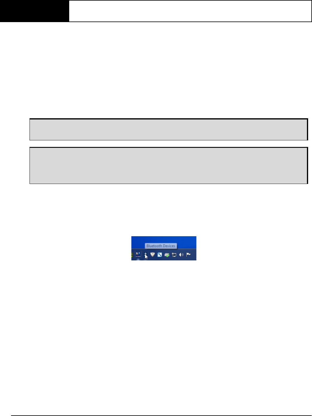
SMART6 User Manual Rev 0B 39
Chapter 5 Bluetooth Configuration
Bluetooth is a wireless radio communication standard designed for use over short ranges (within 10 m). This
chapter describes how to use the Bluetooth interface on the SMART6.
5.1 Bluetooth Wireless Technology on the SMART6 receiver
Bluetooth wireless technology is configured on the SMART6’s internal COM3 port. After your computer is
configured for Bluetooth operation, use HyperTerminal or NovAtel Connect to communicate through COM3.
To log data over the Bluetooth port, specify COM3 as the output port (e.g. log com3 bestposa ontime 1).
5.2 Pairing with a new SMART6
To pair with an SMART6 in range:
1. Power on the SMART6.
2. Double-click the Bluetooth icon in the notification area, see Figure 3 on page 39. The Bluetooth Devices
window opens, see Figure 4 on page 40.
Figure 3: Bluetooth Icon
Ensure that your computer is equipped with a built-in, or external plug-in, Bluetooth adapter and
is already configured with the appropriate Bluetooth driver.
The information in this section is specific to pairing an SMART6 with a Windows 7 based
computer.
For information about pairing the SMART6 with other Bluetooth capable devices, refer to the
devices user documentation.
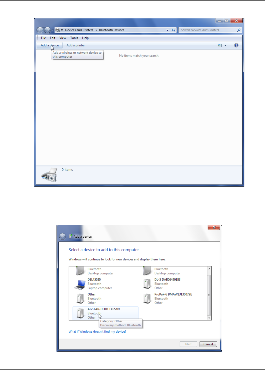
Bluetooth Configuration Chapter 5
SMART6 User Manual Rev 0B 40
Figure 4: Bluetooth Devices Window
3. On the Bluetooth Devices window, click the Add a device button. The Add a device window appears. The
computer searches for any Bluetooth device in range and displays the devices found on the window, see
Figure 5 on page 40.
Figure 5: Add a device window
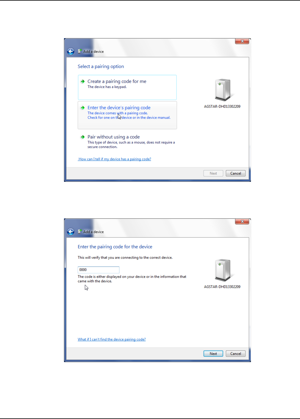
Bluetooth Configuration Chapter 5
SMART6 User Manual Rev 0B 41
4. Select the SMART6 system and click the Next button. The Select a pairing option window appears, see
Figure 6 on page 41.
Figure 6: Add a device - Select a pairing option
5. Click the Enter the device’s pairing code button. The Enter the pairing code for the device window
appears, see Figure 7 on page 41.
Figure 7: Add a device - Enter pairing code
6. Type the SMART6 pairing code, 0000, and click the Next button.
Windows installs the serial port driver and assigns a serial port number to the Bluetooth link. Make a note
of the serial port number assigned. See Figure 8, Bluetooth Link Serial Port on page 42 and Figure 9,
Add a device - Successful on page 42.
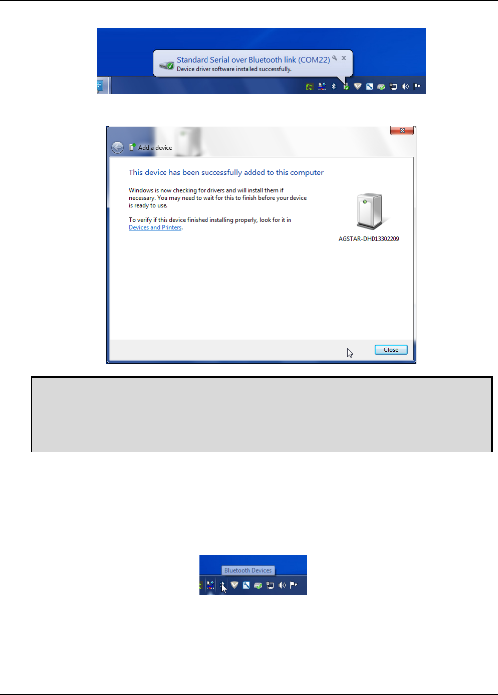
Bluetooth Configuration Chapter 5
SMART6 User Manual Rev 0B 42
Figure 8: Bluetooth Link Serial Port
Figure 9: Add a device - Successful
5.3 Determining the Bluetooth Serial Port
To determine the serial port associated with the Bluetooth link to the SMART6:
1. Double-click the Bluetooth icon in the notification area, see Figure 10 on page 42. The Bluetooth Devices
window opens, see Figure 11 on page 43.
Figure 10: Bluetooth Icon
On some operating systems, the SMART6 must be re-paired every time it is restarted.
To re-pair in Windows 7, click the Bluetooth icon in the notification area and enter the pairing
code when prompted.
For instructions on re-pairing in other operating systems, see the user documentation that came
with the operating system.
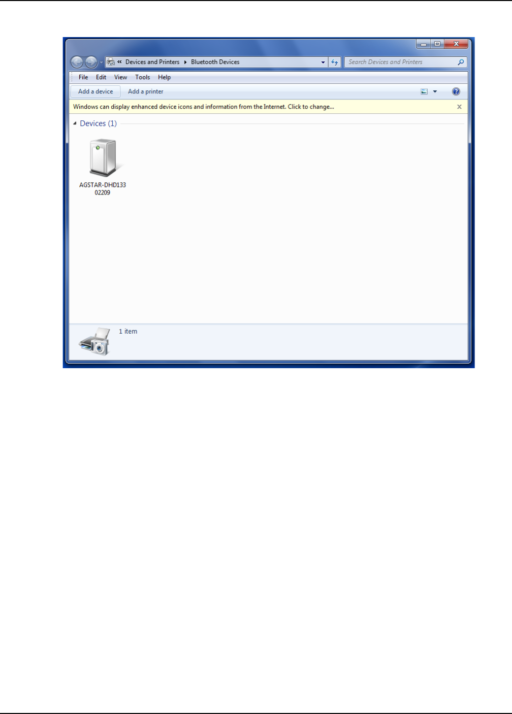
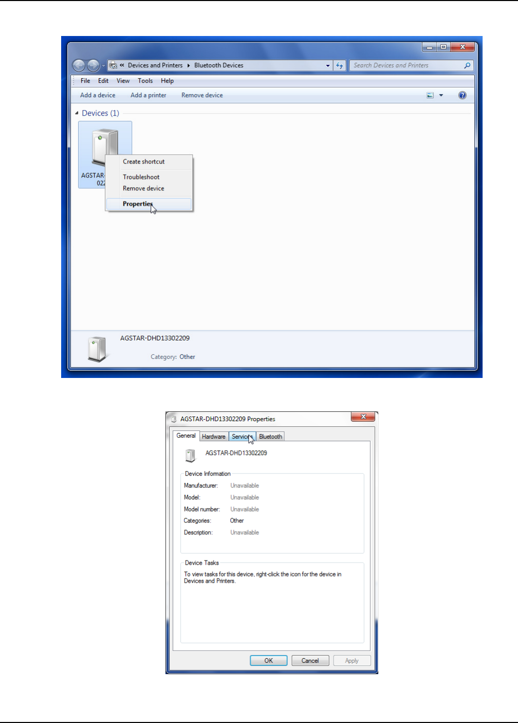
Bluetooth Configuration Chapter 5
SMART6 User Manual Rev 0B 44
Figure 12: Bluetooth Devices Window - Device Menu
Figure 13: Bluetooth Devices Window - Properties
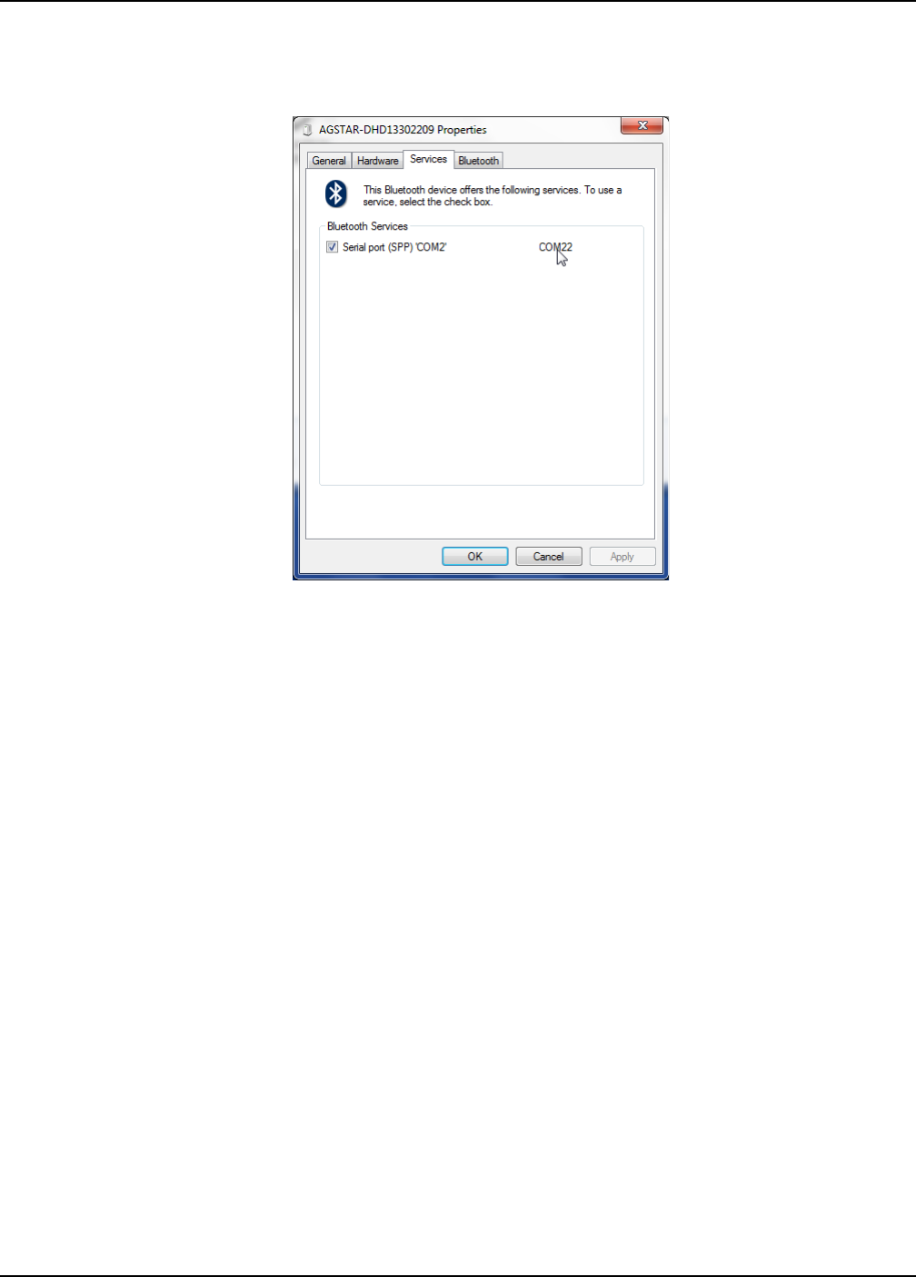
Bluetooth Configuration Chapter 5
SMART6 User Manual Rev 0B 45
3. Click the Services tab. The Services tab displays the serial port information about the Bluetooth link to
the SMART6. See Figure 14 on page 45.
Figure 14: Properties - Services Tab
5.4 Communicate with the SMART6 Using Bluetooth Wireless Technology
1. Open a terminal program (HyperTerminal, for example) and configure it to the serial port assigned to the
Bluetooth link. If you do not know the serial port information, see Section 5.3, Determining the Bluetooth
Serial Port on page 42.
2. Configure the port settings as follows:
9600 bps, no parity, 8 data bits, 1 stop bit, no handshaking, echo off
3. Through the terminal program, connect to the Bluetooth serial port and verify the connection.
4. Type the following VERSION log request into the command prompt to ensure that the connection works:
log version

SMART6 User Manual Rev 0B 46
Appendix A Technical Specifications
A.1 SMART6 Receiver Performance
PERFORMANCEa
a. Typical values. Performance specifications subject to GPS system characteristics, US DOD operational degradation,
ionospheric and tropospheric conditions, satellite geometry, baseline length, multipath effects and the presence of intentional or
unintentional interference sources.
Channel Configuration
120 Channels can be configured to track:
L1 GPS
L2 GPS (optional)
L2C GPS (optional)
L1 GLONASS (optional)
L2 GLONASS (optional)
Galileo E1 (optional)
BeiDou B1 (optional)
SBASb
b. Satellite Based Augmentation Systems (SBAS) include WAAS (North America), EGNOS (Europe) and MSAS (Japan).
Horizontal Position Accuracy (RMS)c
c. GPS only.
Single Point 1.5 m
Single Point L1/L2 1.2 m
SBASc0.6 m
DGPS 0.4 m
RT-2™ 1 cm + 1 ppm
Measurement Precision (RMS)
GPS GLO
L1 C/A code 4 cm 8 cm
L1 carrier phase 0.5 mm 1 mm
L2 P(Y) coded
d. L2 P for GLONASS.
8 cm 8 cm
L2 carrier phased1 mm 1 mm
L2C codee
e. L2 C/A for GLONASS.
8 cm 8 cm
L2C carrier phasee0.5 mm 0.5 mm
Maximum Data Ratef
f. Model specific.
Measurements up to 50 Hz
Position up to 50 Hz
Time to First Fix Cold Startg
g. Typical value. No almanac or ephemerides and no approximate position or time.
<50 s
Hot Starth
h. Typical value. Almanac and recent ephemerides saved and approximate time entered. For more information, refer to the
“SETAPPROXTIME” command in the OEM6 Family Firmware Reference Manual found on our web site at www.novatel.com/
support/firmware-software-and-manuals/product-manuals-and-doc-updates/.
<35 s
Signal Reacquisition L1 0.5 s (typical)
L2 1.0 s (typical)
Time Accuracy 20 ns RMS
Velocity Accuracyi
i. Export licensing restricts operation to a maximum velocity of 515 metres per second.
0.03 m/s RMS

SMART6 User Manual Rev 0B 47
A.2 SMART6 Specifications
INPUT/OUTPUT CONNECTORS
SMART6 Communication/Power
+8 to +36 V DC at 2.9 W a
For the cable pinouts and drawings, see Section A.2.1, SMART6
Communication/Power Cable (01018999) on page 49
a. Power consumption values for GPS L1/L2.
Serial Com Ports RS-232 F Compliant (Rx and Tx signals only)
CAN SAE J1939/ ISO 11783/ ISO 11898 Compatible
Emulated Radar Output
High = Supply Voltage -0.5V Minimum
Low = 0.5V Maximum
Load = 3K Ohm Minimum
PPS Output 3.3 V CMOS Logic Compatible
MKI Input 3.3 V CMOS Logic/5 V Tolerant
INPUT/ OUTPUT CONNECTOR PROTECTION
Electrical Conducted/ Coupled
disturbance tolerance
ISO 7637-2:2004
Functional Class A: Pulses 2a, 3a, 3b, 4
Functional Class C: Pulses 1, 2b
LED INDICATORS
Power, Error and Position Valid Refer to Section 2.2.1, Status Indicators on page 18 for details
PHYSICAL
Size 80.9 x 155 mmb
b. denotes diameter, here and in the Dimensions graphic on page 48.
c. See also the Notice section of this manual starting on page 9.
Weight <550 g
Mounting
2 x magnetic mount
4 x M4 screw inserts
Optional mounting plate
ENVIRONMENTAL c
Operating Temperature -40C to +75C
Storage Temperature -55C to +90C
Humidity Not to exceed 95% non-condensing
Immersion MIL-STD-810G Method 512.5 Procedure 1
Shock MIL-STD-810G Method 516.6
Solar Radiation EN60950-22 8.2
MIL-STD-810G Method 505.5
Salt Fog MIL-STD-810G, 509.5
Sand and Dust MIL-STD-810G, 510.5
ENVIRONMENTAL c
Vibration Random: MIL-STD-810G, Method 514.6E-I
Sinusoidal: IE 68-2-6 ASAE ER455, 5.15.2 Level 1
Compliance FCC, IC, CE
Ingress Protection Rating IP67
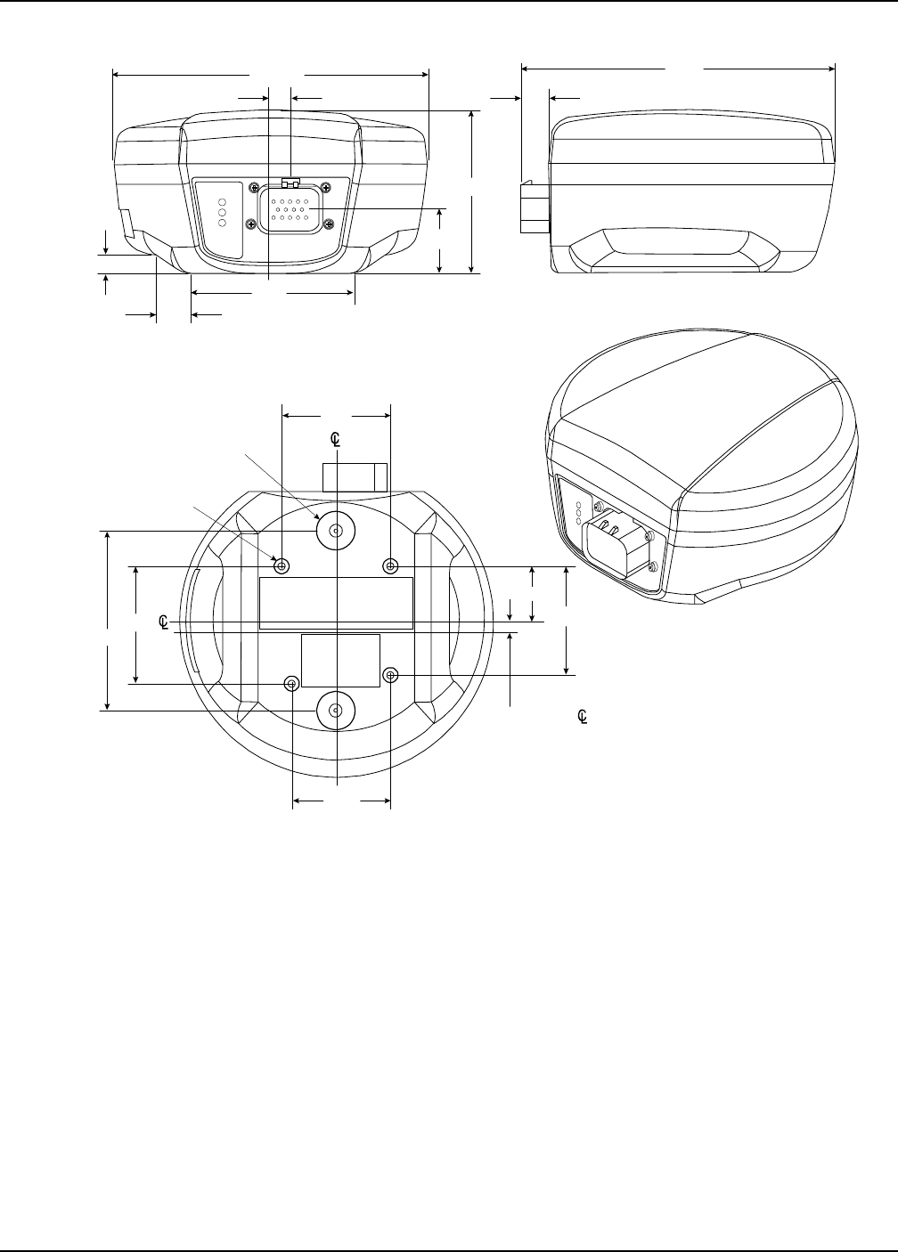
SMART6 User Manual Rev 0B 48
Figure 17: SMART6 Dimensions
Ø155.00
9.5
53.9
48.79
13.7
80.9
53.9
26.9
5.3 Antenna
89.0 58.2
M4 x 0.7
10 DEEP x 4
Neodymium Rare
Earth Maget x2
155.2
31.5
77.3
17.9 x 2
9.0
x 2
Dimensions are in millimeters
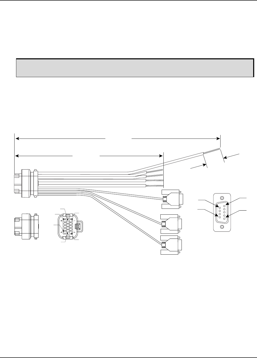
SMART6 User Manual Rev 0B 49
A.2.1 SMART6 Communication/Power Cable (01018999)
The SMART6 cable (refer to Figure 18, SMART6 Communication/Power Cable), provides a means of
supplying power from a battery while operating in the field. The exposed wires (red for positive and black for
negative) can then be connected to a vehicular power circuit (or equivalent) protected by a 5 A fast blow fuse
(user supplied). The cable has three DB-9 connectors to accommodate a computer serial (RS-232)
communication port, a modem or radio transmitter to propagate differential corrections (refer to the user
supplied modem or radio transmitter user guide for information on its connectors).
In addition, there are a number of bare wires where the outer insulation is cut away but the wires beneath
remain intact. See Table 5, SMART6 Communication/Power Cable Pinouts on page 50 for their pinouts. For
more information on mating connectors and part numbers, see Table 6, SMART6 Mating Connectors on
page 51.
This cable is RoHS compliant.
Figure 18: SMART6 Communication/Power Cable
Bluetooth wireless technology uses the COM3 port. When Bluetooth wireless technology is
enabled, COM3 is not available on the SMART6 connector or the cable.
Pin 5
30.0 ± 3.0
Typical 5 Places
7600 +5%/-0
(length when straight)
4600 +155/-0
(length when straight)
Pin 1
Pin 6
Pin 9
J1
J2
J3
J4
Pin 1
Pin 5
Pin 9
Pin 14
Pin 10
Pin 16
Dimensions are in millimeters

SMART6 User Manual Rev 0B 50
Table 5: SMART6 Communication/Power Cable Pinouts
A.2.2 SMART6 Connector and Cable Requirements
Custom cables for installing the SMART6 can be created using the following guidelines:
• Wire size: must be 0.5 mm-1.25 mm (20-16 AWG)
• Batt+ connection must be protected by 5 A fast blow fuse
• Serial data signals (TxD, RxD, signal ground) must be run in shielded cable. Connect shields
to ground at SMART6 end only
• CAN signal conductors must be twisted (40 twists/m, 12 twists/ft)
• Use only the recommended mating connectors listed below. Use only gold plated pins
The connector used in the SMART6 is an “AMPSEAL” dust and water sealed type produced by Tyco. The
following part numbers pertain to the mating connector required to make connections to the SMART6. These
numbers are provided for information only and are not available from NovAtel as separate parts.
Signal Name J1 J2 J3 J4 Label
COM1_TXD 1 2
COM1_RXD 2 3
COM2_TXD 3 2
COM2_RXD 4 3
COM3_TXD 8 2
COM3_RXD 13 3
COM1 GND
5
5
COM2 GND 5
COM3 GND 5
MKI GND MKI GND
Emulated Radar GND ER GND
Pulse Per Second GND PPS GND
CAN+ 6 CANI+
CAN- 7 CANI-
PWR RET (GND) 9 BATT-
Emulated Radar Out 10 ER_OUT
EVENT MARK IN 11 MKI
PPS 12 PPS
PWR INPUT 14 BATT+
Failure to observe the given cable construction guidelines and fusing requirements in this
section may result in damage to the wiring or equipment and voiding the warranty.
NovAtel recommends tying to ground any floating input lines.

SMART6 User Manual Rev 0B 51
Table 6: SMART6 Mating Connectors
Table 7 details the part numbers for recommended fuses and fuse holders. These numbers are provided for
information only and are not available from NovAtel as separate parts.
Table 7: Recommended Fuse and Fuse Holders
Product Part Description Company Part Number
SMART6 mating connector (J1 - Figure 18 on
page 49)
14-pin sealed receptacle
housing-black Tyco/AMP 776273-1
Gold plated pins (20-16 AWG) for (J1) SMART6
connector
Gold plated pins for SMART6 connector/strip
Pins, loose piece Tyco/AMP 770854-3
Pins, strip (reel) Tyco/AMP 770520-3
Seal Plug for unused pins on mating connector. (All
connector positions must be populated with a pin or
seal plug to achieve the IP-67 rating for the cable
connection.)
Seal plug Tyco/AMP 770678-1
Fuse Recommended Fuse/Fuse Holder
12 V System Fuse (standard size blade)
ATO Silver Blade Fuse 5 A (32
V) Littelfuse 0287005
Or Equivalent
12 V System Fuse (mini size blade) Mini Blade Fuse 5 A (32 V) Littelfuse 0297005
Or Equivalent
12 V System Fuse
High Reliability, Harsh Environment
(standard size blade)
FKS ATO Blade Fuse 5A (80 V) Littelfuse 166.7000.450
Or Equivalent
Inline Fuse Holder,
(for standard size blade)
Waterproof ATO Fuse Holder Littelfuse FHAC0001
Or Equivalent
Inline Fuse Holder,
(for mini size blade)
Waterproof Mini Fuse Holder Littelfuse 0FHM0001
Or Equivalent

SMART6 User Manual 52
Appendix B Commands
The SMART6 firmware implements the OEM6 family command set, documented in the OEM6 Family
Firmware Reference Manual. Commonly used SMART6 commands are summarized in Table 8, SMART6
Commands and documented in this appendix.
Table 8: SMART6 Commands
The arguments for each of these commands are described in the following sections.
For a complete listing and description of the other commands that the SMART6, an OEM6 based receiver, is
capable of processing, refer to the OEM6 Family Firmware Reference Manual.
B.1 SYNTAX CONVENTIONS
The following rules apply when entering commands, at the command prompt, from a keyboard.
1. Courier font is used to illustrate program output or user input.
2. References to other commands, logs or any of their fields are shown in italics.
3. The commands are not case sensitive. For example, you could type either RESET or reset.
4. Except where noted, either a space or a comma can separate commands and their required entries. For
example, you could type either fix position 51.11358042 -114.04358013 1059.4105 or fix
position 51.11358042, -114.04358013, 1059.4105.
5. At the end of a command, a carriage return is required. For example, press <Enter> or <Return> on your
keyboard.
6. Responses are provided to indicate whether or not an entered command was accepted. The format of
the response depends on the format of the command. Refer to the OEM6 Family Firmware Reference
Manual for more information.
7. Optional parameters are indicated by square brackets ( [ ] ). For commands that contain optional
parameters, the value used if the optional parameter is not specified is given in the syntax table for the
command.
8. Data format definitions, as specified in the “Format” field, are detailed in the OEM6 Family Firmware
Reference Manual. Note that all binary data is little-endian byte-ordered.
ASCII Command Message ID Description
BTCONTROL 8205 Enable or disable Bluetooth wireless technology.
COM 4 Configure the receiver serial port.
FRESET 20 Factory reset (existing OEM6 commands extended to SMART6)
LOG 1 Request logs from the receiver
$PMDT 8200 Configure the Tilt Compensation function (SMART6 command)
RADARCFG 8192 Configure the Emulated Radar signal output (SMART6 command)
SETCANNAME 1091 Set the CAN name fields.

SMART6 User Manual Rev 0B 53
B.2 BTCONTROL Enable/Disable Bluetooth wireless technology
The BTCONTROL command enables or disables the Bluetooth module. To ensure no possibility of
interference, when the module is disabled it is completely powered down.
Message ID: 8205
Abbreviated ASCII Syntax:
BTCONTROL switch
Factory Default:
The Bluetooth module is enabled by default.
Example 1 to disable Bluetooth wireless technology:
btcontrol disable
Example 2 to enable Bluetooth wireless technology:
btcontrol enable
Field Data Description Binary
Bytes
Binary
Format
Binary
Offset
1BTCONTROL
header
This field contains the command name or the message
header depending on whether the command is abbreviated
ASCII, ASCII or binary.
--0
2 switch Enable or disable Bluetooth wireless technology
0 = ENABLE
1 = DISABLE
(default = ENABLE)
4EnumH
1. To enable the current state of the Bluetooth module to persist across receiver resets and
power-ups, issue a SAVECONFIG command.
2. Changing the Bluetooth wireless technology from disabled to enabled takes several
seconds to execute. This means that, even though the user will get an immediate “OK>”
response followed by the COM prompt, the Bluetooth module may not be ready for
communication.

SMART6 User Manual Rev 0B 54
B.3 COM Configure COM Port
This command is used to configure the receiver’s serial ports.
The current COM port configuration can be reset to the default state at any time by sending two hardware
break signals of 250 milliseconds each, spaced by fifteen hundred milliseconds (1.5 seconds), with a pause
of at least 250 milliseconds following the second break. This will:
• Stop the logging of data on the current port (see UNLOGALL command in the OEM6 Family Firmware
Reference Manual).
• Clear the transmit and receive buffers on the current port.
• Return the current port to its default settings.
• Set the interface mode to NovAtel for both input and output (see INTERFACEMODE command in the
OEM6 Family Firmware Reference Manual).
Message ID: 4
Abbreviated ASCII Syntax
COM [port] bps [parity[databits[stopbits[handshake[echo[break]]]]]]
Factory Default:
COM COM1 9600 N 8 1 N OFF ON
COM COM2 9600 N 8 1 N OFF ON
COM COM3 9600 N 8 1 N OFF ON
ASCII Example:
COM COM1 57600 N 8 1 N OFF ON
Baud rates higher than 115,200 bps are not supported by standard computer hardware. Special
computer hardware may be required for higher rates, including 230400 bps, 460800 bps and
921600 bps. Also, some computers have trouble with baud rates beyond 57600 bps.
On SMART6 receivers with Bluetooth wireless technology, the default settings for COM3 are:
com3 115200 n 8 1 cts off off
Changing the COM3 serial port settings could interfere with the ability to communicate using
Bluetooth.
Use the COM command before using the INTERFACEMODE command on each port.
Watch for situations where the COM ports of two receivers are connected together and the
baud rates do not match. Data transmitted through a port operating at a slower baud rate may
be misinterpreted as break signals by the receiving port if it is operating at a higher baud rate.
This is because data transmitted at the lower baud rate is stretched relative to the higher baud
rate. In this case, configure the receiving port to have break detection disabled using the COM
command.

SMART6 User Manual Rev 0B 55
Field Field Type ASCII Value Binary
Value Description Binary
Format
Binary
Bytes
Binary
Offset
1COM header - - This field contains the command name or
the message header depending on whether
the command is abbreviated ASCII, ASCII
or binary.
- H 0
2port 1COM1 Select COM port 1 to configure Enum 4 H
2COM2 Select COM port 2 to configure
3COM3 Select COM port 3 to configure
6THISPORT Select the current COM port (default)
8ALL Select all COM ports
3bps/baud 300, 600, 900, 1200, 2400,
4800, 9600, 19200, 38400,
57600, 115200, or 230400
Communication baud rate (bps).
Bauds of 460800 and 921600 are also
available on COM1 of OEM6 based
products
ULong 4H+4
4parity N 0 No parity (default) Enum 4H+8
E 1 Even parity
O 2 Odd parity
5databits 7 or 8 Number of data bits
(default = 8)
ULong 4H+12
6stopbits 1 or 2 Number of stop bits
(default = 1)
ULong 4H+16
7handshake N 0 No handshaking
(default)
Enum 4H+20
XON 1XON/XOFF software handshaking
8echo OFF 0No echo
(default)
Enum 4H+24
ON 1Transmit any input characters as they are
received
9break OFF 0Disable break detection Enum 4H+28
ON 1Enable break detection (default)

SMART6 User Manual Rev 0B 56
B.4 FRESET Clear Selected Data from NVM and Reset
This command clears data that is stored in non-volatile memory. Such data includes the almanac, ephemeris
and any user specific configurations. The commands, ephemeris and almanac related data can be cleared by
using the STANDARD target. The model can only be cleared by using the MODEL target. The receiver is forced
to hardware reset. In addition, values entered using the CLOCKCALIBRATE command can only be cleared by
using the CLKCALIBRATION target.
Issuing the FRESET command affects Tilt as follows:
• Tilt sensor level is restored to the factory default
• Tilt enable/disable is not be affected
Message ID: 20
Abbreviated ASCII Syntax:
FRESET [target]
Input Example:
FRESET COMMAND
FRESET STANDARD (which is also the default) causes any commands, ephemeris, GNSS and
almanac data previously saved to NVM to be erased.
If you are receiving no data or random data from your receiver, try the following before
contacting NovAtel:
• Verify that the receiver is tracking satellites
• Check the integrity and connectivity of power and data cables
• Verify the baud rate settings of the receiver and terminal device (your computer or data
logger)
• Switch COM ports
• Issue a FRESET command
Field Field Type ASCII
Value
Binary
Value Description Binary
Format
Binary
Bytes
Binary
Offset
1FRESET
header
- - This field contains the command name
or the message header depending on
whether the command is abbreviated
ASCII, ASCII or binary.
- H 0
2target See Table 9, FRESET
Target on Page 57
What data is to be reset by the receiver.
(default=STANDARD)
Enum 4 H

SMART6 User Manual Rev 0B 57
Table 9: FRESET Target
Binary ASCII Description
0STANDARD Resets commands, ephemeris and almanac (default).
1COMMAND Resets the stored commands (saved configuration)
2GPSALMANAC Resets the stored GPS almanac
3GPSEPHEM Resets the stored GPS ephemeris
4GLOEPHEM Resets the stored GLONASS ephemeris
5MODEL Resets the currently selected model
10 USERDATA Resets SMART6 only commands
11 CLKCALIBRATION Resets the parameters entered using the CLOCKCALIBRATE command
20 SBASALMANAC Resets the stored SBAS almanac
21 LAST_POSITION Resets the position using the last stored position
31 GLOALMANAC Resets the stored GLONASS almanac
52 PROFILEINFO Resets the stored profile configurations

SMART6 User Manual Rev 0B 58
B.5 LOG Request Logs from the Receiver
Many different types of data can be logged using several different methods of triggering the log events. Every
log element can be directed to any combination of the three COM ports. The ONTIME trigger option requires
the addition of the period parameter. See the OEM6 Family Firmware Reference Manual for further
information and a complete list of data log structures. The LOG command tables in this section show the
ASCII command format.
The optional parameter [hold] prevents a log from being removed when the unlogall command, with its
defaults, is issued. To remove a log that was invoked using the [hold] parameter requires the specific use of
the unlog command. To remove all logs that have the [hold] parameter, use the UNLOGALL command with
the held field set to 1.
The [port] parameter is optional. If [port] is not specified, [port] is defaulted to the port that the command was
received on.
Message ID: 1
Abbreviated ASCII Syntax:
LOG [port] message [trigger [period [offset [hold]]]]
Abbreviated ASCII Example 1:
LOG COM1 BESTPOS ONTIME 7 0.5 HOLD
The above example shows BESTPOS logging to COM port 1 at 7 second intervals and offset by 0.5 seconds
(output at 0.5, 7.5, 14.5 seconds and so on). The [hold] parameter is set so logging is not disrupted by the
unlogall command.
To send a log only one time, the trigger option can be ignored.
Abbreviated ASCII Example 2:
LOG COM1 BESTPOS ONCE 0.000000 0.000000 NOHOLD
Refer to the Command Formats section of the OEM6 Family Firmware Reference Manual for additional
examples.
1. The OEM6 family of receivers can handle 64 logs at a time. If it is more than 64 logs at a
time, the receiver responds with an Insufficient Resources error.
2. Maximum flexibility for logging data is provided to the user by these logs. The user is
cautioned, however, to recognize that each log requested requires additional CPU time and
memory buffer space. Too many logs may result in lost data and degraded CPU
performance. Receiver overload can be monitored using the idle time field and buffer
overload bits of the Receiver Status in any log header.
3. Polled log types do not allow fractional offsets or ONTIME rates faster than 1 Hz.
4. Use the ONNEW trigger with the MARKTIME or MARKPOS logs.
5. Only the MARKPOS or MARKTIME logs and ‘polled’ log types are generated, on the fly, at
the exact time of the mark. Synchronous and asynchronous logs output the most recently
available data.
6. If the ONTIME trigger is used with asynchronous logs, the time stamp in the log does not
necessarily represent the time the data was generated but rather the time when the log is
transmitted.
1. In NovAtel Connect there are two ways to initiate data logging to the receiver's serial ports:
- the LOG command in the Console window or
- use the interface provided in the Logging Control window.
2. Only the ASCII/Abbreviated ASCII log table is included in this manual. Refer to the LOG
command in the OEM6 Family Firmware Reference Manual for binary log details.

SMART6 User Manual Rev 0B 59
Factory Default:
LOG COM1 RXSTATUSEVENTA ONNEW 0 0 HOLD
LOG COM2 RXSTATUSEVENTA ONNEW 0 0 HOLD
LOG COM3 RXSTATUSEVENTA ONNEW 0 0 HOLD
Field Field
Name ASCII Value Description Field
Type
1LOG
(ASCII)
header
- This field contains the command name or the message
header depending on whether the command is abbreviated
ASCII or ASCII respectively
-
2 port See Table 10, Detailed
Serial Port Identifiers on
page 60
Output port
(default = THISPORT)
Enum
3 message Any valid message name,
with an optional A or B
suffix
Message name of log to output Char [ ]
4 trigger ONNEW Output when the message is updated (not necessarily
changed)
Enum
ONCHANGED Output when the message is changed
ONTIME Output on a time interval
ONNEXT Output only the next message
ONCE Output only the current message (default)
ONMARK Output when a pulse is detected on the mark 1 input, MK1I
5 period Any positive double value
larger than the receiver’s
minimum raw
measurement period
Log period (for ONTIME trigger) in seconds
(default = 0)
Double
6 offset Any positive double value
smaller than the period
Offset for period (ONTIME trigger) in seconds. To log data
at 1 second after every minute, set the period to 60 and the
offset to 1 (default = 0)
Double
7hold NOHOLD Allow log to be removed by the UNLOGALL command
(default)
Enum
HOLD Prevent log from being removed by the UNLOGALL
command

SMART6 User Manual Rev 0B 60
Table 10: Detailed Serial Port Identifiers
ASCII Port Name Hex Port Value Decimal Port Value a
a. Decimal port values 0 through 16 are only available to the UNLOGALL command and cannot be used
in the UNLOG command or in the binary message header.
Description
NO_PORTS 0 0 No ports specified
COM1_ALL 1 1 All virtual ports for COM port 1
COM2_ALL 2 2 All virtual ports for COM port 2
COM3_ALL 3 3 All virtual ports for COM port 3
THISPORT_ALL 6 6 All virtual ports for the current port
ALL_PORTS 8 8 All virtual ports for all ports
XCOM1_ALL 9 9 All virtual COM1 ports
XCOM2_ALL 10 10 All virtual COM2 ports
XCOM3_ALL 11 17 All virtual COM3 ports
COM1 20 32 COM port 1, virtual port 0
COM1_1 21 33 COM port 1, virtual port 1
...
COM1_31 3f 63 COM port 1, virtual port 31
COM2 40 64 COM port 2, virtual port 0
...
COM2_31 5f 95 COM port 2, virtual port 31
COM3 60 96 COM port 3, virtual port 0
...
COM3_31 7f 127 COM port 3, virtual port 31
THISPORT c0 192 Current COM port, virtual port 0
THISPORT_31 df 223 Current COM port, virtual port 31
XCOM1 1a0 416 Virtual COM1 port, virtual port 0
XCOM1_1 1a1 417 Virtual COM1 port, virtual port 1
...
XCOM1_31 1bf 447 Virtual COM1 port, virtual port 31
XCOM2 2a0 672 Virtual COM2 port, virtual port 0
XCOM2_1 2a1 673 Virtual COM2 port, virtual port 1
...
XCOM2_31 2bf 703 Virtual COM2 port, virtual port 31
...
XCOM3 9a0 2464 Virtual COM3 port, virtual port 0
...
XCOM3_31 9bf 2495 Virtual COM3 port, virtual port 31
For detailed information on virtual ports, refer to the LOG command in the OEM6 Family
Firmware Reference Manual.

SMART6 User Manual Rev 0B 61
B.6 $PMDT Configure Tilt Compensation
Use this NMEA command to configure the Tilt Compensation function.
Syntax
$PMDT,[command],[parameters]*cksum
Refer to Tilt Compensation on page 19 and Tilt Compensation on page 30 for setup instructions.
Host Description Command Format Tilt Sensor Response
ua bSet GPS Sensor
Height
To set the GNSS sensor height in feet and
inches:
$PMDT,u,,ff,ii*cksum crlf
Example: To set the GNSS sensor height to
12 ft 6 in, the command is:
$PMDT,u,,12,6*40
Note: Feet and inches are entered as
integers. You can enter feet and inches, but
not feet, inches and metres.
Response to the “u” command:
$PMDT,<,GNSS sensor height (inches):nnnnn crlf
where nnnnn is a five digit integer, sensor height in
inches.
In this example, the Tilt Sensor response is:
$PMDT,<,GNSS sensor height (inches): 00150
To set the GNSS sensor height in metres:
$PMDT,u,,,,mmm.mmm*cksum crlf
Example: To set the GNSS sensor height to
3.5 metres, the command is:
$PMDT,u,,,,3.5*7C
Response to the ”u” command:
$PMDT,<,GNSS sensor height (inches):nnnnn crlf
where nnnnn is a five digit integer, sensor height in
inches.
In this example, the Tilt Sensor response is:
$PMDT,<,GNSS sensor height (inches): 00137
l Set Field Level $PMDT,l*cksum crlf
Example:
$PMDT,l*4D
Response to the “l” command:
$PMDT,<,Level state set crlf
Example:
$PMDT,<,Level state set
x Update Flash
Values
To update flash values (needs to follow any
height or level command that is not done each
time you power up):
$PMDT,x*cksum crlf
Example: $PMDT,x*59
Response to the “x” command:
$PMDT,<,Flash updated crlf
Example:
$PMDT,<,Flash updated
a. If all fields in the u command are zero or null, the current height is transmitted without change (with the format shown
above).
b. If an invalid entry is received (>500 inches), the response is:
$PMDT,<Max legal height exceeded: nnnnn and will be ignored clrf
For example, if you enter 42 ft 6 in, you will get the following response:
$PMDT,<,Max legal height exceeded: 00510 and will be ignored
$PMDT,<,GPS sensor height (inches): 00150

SMART6 User Manual Rev 0B 62
B.7 RADARCFG Configure the ER Output
Use this command to configure the Emulated Radar (ER) output. ER is available through the SMART6
interface cable, see Table 5, SMART6 Communication/Power Cable Pinouts on page 50 for pin-out details.
Message ID: 8192
Syntax
radarcfg switch freq_step update_rate resp_mode threshold
Table 11: Response Modes
Example 1 to disable radar emulation: radarcfg disable 26.11 1 1 2
Example 2 to set the frequency step to 36.11 Hz/kph,
update rate to 1 Hz and no smoothing: radarcfg enable 36.11 1 1 2
Field Data Description Bytes Format Units Offset
1 Header This field contains the command name or the message
header depending on whether the command is
abbreviated ASCII, ASCII or binary.
--0
2 switch Enable or disable radar emulation
0 = ENABLE
1 = DISABLE
(default = enable)
4 Enum none H
3 freq_step Frequency step per kilometer per hour.
Range: 26.11, 28.12 or 36.11
(default = 36.11)
8 Double Hz/kph H+4
4 update_rate Specify how often to update radar output
Range: 1, 2, 5, 10, 20
(default = 10)a
4 Integer Hz H+12
5 resp_mode Specify the time response mode, over which to average
velocity samples, see Table 11, Response Modes.
(Default = 500)a
4 Integer none H+16
6 threshold The threshold is only applicable when the response mode
is set to 2. The response time is 1000 ms when the
velocity is greater than this value, otherwise, it is 500 ms.
Range: 2-50 kph
(default = 5 kph)
8 Double kph H+20
a. The number of samples used for smoothing depends on both the update_rate and resp_mode parameters. For instance, if
the update_rate is 5 Hz and the resp_mode is 2000ms, the number of samples used will be 10.
Mode Description
2000 2000 ms
The time period over which to smooth
velocity samples
1000 1000 ms
500 500 ms (default)
2 Automatically switches between 1000 and 500 ms
1 Performs no smoothing

SMART6 User Manual Rev 0B 63
B.8 SETCANNAME Sets the CAN name fields
This command sets the CAN device name fields.
Message ID: 1091
Abbreviated ASCII Syntax:
setcanname ManufacturerCode IndustryGroup DeviceClass DeviceClassInstance Function FunctionInstance
ECUInstance PreferredAddress
Factory Default:
setcanname 305 2 0 0 23 0 0 28 can2
Field Field Type ASCII
Value
Binary
Value Description Binary
Format
Binary
Bytes
Binary
Offset
1 SETCANNAME
header
- - This field contains the command name or
the message header depending on whether
the command is abbreviated ASCII, ASCII
or binary.
-H0
2 ManufacturerCode CAN module's Manufacturer Code ULong 4 H
3 IndustryGroup Industry group number (default = 2) ULong 4 H+4
4 DeviceClass 11783-5 Device class (default = 0) ULong 4 H+8
5 DeviceClassInstance 11783-5 Device class instance (default = 0) ULong 4 H+12
6 Function 11783-5 Function (default = 23) ULong 4 H16
7 FunctionInstance 11783-5 Function instance (default = 0) ULong 4 H+20
8 ECUInstance 11783-5 ECU Instance (default = 0) ULong 4 H+24
9 PreferredAddress Device default address on start up
(default=28)
ULong 4 H+28
10 CanPort CAN port to use (default = can2)
Note: This field must be set to can2.
ULong 4 H+32

SMART6 User Manual Rev 0B 64
Appendix C Logs
C.1 Position Logs
C.1.1 NMEA Logs
The NMEA logs (receiver outputs) supported by the SMART6 are summarized in Chapter 3 of the OEM6
Family Firmware Reference Manual in section "NMEA Standard Logs". The available logs include:
• GPGGA, which outputs a log of position system fix data and undulation. There are variants
of GPGGA, specifically:
- GPGGARTK, which has greater precision than GPGGA but with the loss of the undulation field
- GPGGALONG, which has both greater precision and the undulation field
• GPVTG, which outputs track made good and ground speed
Each of the available NMEA standard logs is described in more detail in its own section of Chapter 3 of the
OEM6 Family Firmware Reference Manual.
The steps for configuring the receiver output, through the command line are:
1. Configure the communication port using the COM command, described in Section B.3, COM Configure
COM Port on page 54. To set COM port 2 as follows:
enter the following string:
com com2 9600 n 8 1 n off on
2. Select and configure the NMEA string to output. The information is described in Chapter 3 Data Logs of
the OEM6 Family Firmware Reference Manual, in the section for the particular log. For example, to log
gpgga (position system fix data and undulation) at 2 Hz, enter the following string:
log gpgga ontime 0.5
You can configure the log to output at various frequencies, as described in LOG Request Logs from the
Receiver on page 58.
The above command line operations can also be carried out through NovAtel Connect. Information about
configuring the communication port can be found in NovAtel Connect online help. The procedure for adding a
NMEA log through NovAtel Connect is summarized as follows:
1. In the Logging control window, click Logging to one or more of the receiver's serial ports. The Add Log
window displays.
2. Beside Select list, select Complete List or NMEA List.
3. Beside Log to file, select the NMEA log you want to add.
4. Select the port.
5. Configure the remaining fields then click Add.
Bit Rate 9600
Parity none
Data Bits 8
Stop Bits 1
Handshaking None
Echo Off
Break On

SMART6 User Manual Rev 0B 65
C.1.2 NovAtel Position Logs
In addition to NMEA logs, NovAtel supports a range of non-NMEA position logs, described in the OEM6
Family Firmware Reference Manual, including:
• BESTPOS: This log contains the best available position computed by the receiver, for example:
log bestposa ontime 0.5
• BESTXYZ: This log contains the receiver’s best available position and velocity in ECEF coordinates, for
example:
log bestxyza ontime 1
C.2 Other Logs
The SMART6 firmware generates the logs in Table 12, SMART6 Logs in Alphabetical Order, in addition to
those of the OEM6 Family log set. Refer to the OEM6 Family Firmware Reference Manual, which also
contains procedures and explanations related to data logging and is available from our web site at:
www.novatel.com/support/firmware-software-and-manuals/product-manuals-and-doc-updates/
Table 12: SMART6 Logs in Alphabetical Order
Message ID ASCII Log Description
8193 RADARSIGNAL Radar signal and position information
(New SMART6 log)
37 VERSION Hardware versions, software versions, and serial numbers
(Existing OEM6 log extended to SMART6)

SMART6 User Manual Rev 0B 66
C.2.1 RADARSIGNAL ER Signal and Position Information
This log contains position and Emulated Radar (ER) signal information.
Message ID: 8193
Log Type: Asynch
Recommended Input:
log radarsignala onchanged
ASCII Example 1 (stationary SMART6):
#radarsignala,com1,0,61.5,finesteering,1501,248381.628,00000000,8a1c,3723
;sol_computed,waas,0.0139,0.00,0.00*f0d580ca
ASCII Example 2 (moving SMART6):
#radarsignala,com1,0,42.5,finesteering,1428,206179.600,00000000,baa8,3349
;sol_computed,waas,0.3315,2,0.3152,473.97,29.62*c1479c20
Field
#Field type Data Description Format Binary
Bytes
Binary
Offset
1 RADARSIGNAL
header
Log header H 0
2 sol status Solution status, see Table 14, Solution Status on page 67 Enum 4 H
3 vel type Velocity type, see Table 13, Position or Velocity Type on
page 67
Enum 4 H+4
4 speed Speed over ground (m/s) Double 8 H+8
4 varf freq External VARF output frequency (Hz) Double 8 H+16
5 radar freq Radar signal frequency (Hz) as output by the Emulated Radar
Out signal. See Section B.7, RADARCFG Configure the ER
Output on page 62.
Double 8 H+24
6 xxxx 32-bit CRC (ASCII and Binary only) Hex 4 H+32
7 [CR][LF] Sentence terminator (ASCII only) - - -

SMART6 User Manual Rev 0B 67
Table 13: Position or Velocity Type
Table 14: Solution Status
Type (binary) Type (ASCII) Description
0NONE No solution
1 FIXEDPOS Position has been fixed by the FIX POSITION command
2 FIXEDHEIGHT Position has been fixed by the FIX HEIGHT/AUTO command
8 DOPPLER_VELOCITY Velocity computed using instantaneous Doppler
16 SINGLE Single point position
17 PSRDIFF Pseudorange differential solution
18 WAAS Solution calculated using corrections from an SBAS
19 PROPAGATED Propagated by a Kalman filter without new observations
32 L1_FLOAT Floating L1 ambiguity solution
33 IONOFREE_FLOAT Floating ionospheric-free ambiguity solution
34 NARROW_FLOAT Floating narrow-lane ambiguity solution
48 L1_INT Integer L1 ambiguity solution
49 WIDE_INT Integer wide-lane ambiguity solution
50 NARROW_INT Integer narrow-lane ambiguity solution
Solution Status Description
(Binary) (ASCII)
0 SOL_COMPUTED Solution computed
1 INSUFFICIENT_OBS Insufficient observations
2 NO_CONVERGENCE No convergence
3 SINGULARITY Singularity at parameters matrix
4 COV_TRACE Covariance trace exceeds maximum (trace > 1000 m)
5 TEST_DIST Test distance exceeded (maximum of 3 rejections if distance > 10 km)
6 COLD_START Not yet converged from cold start
7 V_H_LIMIT Height or velocity limits exceeded (in accordance with export licensing restrictions)
8 VARIANCE Variance exceeds limits
9 RESIDUALS Residuals are too large
10 DELTA_POS Delta position is too large
11 NEGATIVE_VAR Negative variance
12 Reserved
13 INTEGRITY_WARNING Large residuals make position unreliable
14-17 Reserved for SPAN-capable receivers
18 PENDING When a FIX POSITION command is entered, the receiver computes its own
position and determines if the fixed position is valid a
a. PENDING implies there are not enough satellites being tracked to verify if the FIX POSITION entered into the receiver is valid.
The receiver needs to be tracking two or more GPS satellites to perform this check. Under normal conditions you should only
see PENDING for a few seconds on power up before the GPS receiver has locked onto its first few satellites. If your antenna is
obstructed (or not plugged in) and you have entered a FIX POSITION command, then you may see PENDING indefinitely.
19 INVALID_FIX The fixed position, entered using the FIX POSITION command, is not valid
20 UNAUTHORIZED Position type is unauthorized - HP or XP on a receiver not authorized for it

SMART6 User Manual Rev 0B 68
C.2.2 TILT Compensation
Tilt Compensation affects existing logs as follows:
• NovAtel logs that provide the Extended Solution Status field (BESTPOS and BESTXYZ, both
documented in OEM6 Family Firmware Reference Manual) use the 0x80 bit to flag the fact
that Tilt Compensation is being applied.
• For NMEA GPGGA, GPGGARTK, and GPGGALONG logs, the precision of various fields
indicates whether the Tilt Compensation is being applied.
C.2.3 VERSION HW and SW Versions and Serial Numbers
The Component Type of the VERSION log, refer to the OEM6 Family Firmware Reference Manual, is
extended to include SMART6 information as in Table 15, Component Type.
Table 15: Component Type
[COM1]<VERSION COM1 0 85.0 FINESTEERING 1727 510341.712 00000000 3681 10985
< 1
< GPSCARD "D2LR0GTTR" "BFN12390111" "OEM628-1.01" "OEM060210RN0000"
"OEM060200RB0000" "2012/Sep/13" "13:46:16"
[COM1]
Binary Valuea
a. Unused numbers are reserved for future use.
ASCII Value Description
0 UNKNOWN Unknown Component
1 GPSCARD OEM6 GPSCard Component
3 ENCLOSURE SMART6 Receiver
8 USERINFO User application information component
981073925
(0x3A7A0005)
DB_USERAPPAUTO Auto-starting user application firmware

SMART6 User Manual Rev 0B 69
Appendix D Replacement Parts
The following are lists of the replacement parts available for the NovAtel SMART6 receiver. Should
assistance be required or you need to order additional components, contact your local NovAtel dealer or
Customer Service representative.
D.1 SMART6
D.2 User Manuals
Table 16: SMART6 Product
Part Description NovAtel Part
SMART6 01019123
SMART6 with Tilt 01019125
SMART6 with Bluetooth 01019121
SMART6 with Bluetooth and Tilt 01019127
Cable: 14-pin socket to 3 DB-9 connectors, twisted CAN I/O pair, and other bare wire
connectors (see A.2.1 SMART6 Communication/Power Cable (01018999) on page 49)
01018999
Mounting Plate 70023072
Pole Mount Kit 01019142
Table 17: Reference User Manuals
Part Description NovAtel Part
OEM6 Family Installation and Operation User Manual OM-20000128
OEM6 Family Firmware Reference Manual OM-20000129
The accessories above are also available from www.novatel.com

SMART6 User Manual Rev 0A 70
Index
Symbols
$PMDT command 61, 63
A
accuracy
position 24, 46
velocity 46
almanac
reset 56
antenna
internal 11
specifications 47
AUTH command 38
authorization 38
AUX port 60
B
base station 28
baseline 24
baud rate 22
baud rate, see bps
BESTPOS log 65
BESTXYZ log 65
bidirectional communication 22
bit rate, see bps
Bluetooth
configuration 39
bps 55
break 54–55
BTCONTROL 53
buffer 22
C
cable
integrity 56
serial 22
CAN. See Controller Area Network
Caution 22
CDU software 58
CMR 28
cold start 46
COM command 54
COM port 58
command 52
communication 22
error message 24
example 24
interface 28
multiple 28
port 22
pre-configure 26
prompt 23
RTK 28
commands
in CDU 33
communication
bidirectional 22
Bluetooth 39
CDU 23
computer 22
notice 7
operation 22
port 17, 22
remote terminal 22
COMVOUT command 54
configuration
additional equipment 13
base station 26
Bluetooth 39
CDU 23
non-volatile memory 56
port 22, 54
rover station 27
RTK 28
configuring 31
connector
mounting bracket 15
Controller Area Network 19
copyright 2
Customer Service 56
customer service 33
D
data
Bluetooth 39
format 52
link 25
log 58
port 17, 22
start 23
storage device 25
terminal 22
Warning 24
dealer 33
default
interface mode 28
offset 59
period 59
port 22, 58–59
trigger 59
differential
configuration note 28
corrections 24, 49

Index
SMART6 User Manual Rev 0A 71
operation 24
serial cable 49
setup 25
directional communication 22
distance exceeded 67
E
echo 55
Emulated Radar (ER) 62, 66
operation 31
enable Bluetooth 39
F
factory default
setting 54
features 11, 23, 33, 38
firmware updates 33–34, 38
FRESET command 58
G
GL1DE 29
GPGGA log 64
GPVTG log 64
H
handshaking 22, 55
hardware
enclosure 11
replace 69
required 13
setup 25
header 10
height limit 67
hexadecimal 10
hold 58–59
I
identifier, serial port 60
idle time 22
input
command 23–24
differential 26–27
mark 59
power 15
syntax 52
interface
base or rover 26–27
Bluetooth 39
communication 22
serial 22
introduction 11
L
LED
front 11
power 14, 18
light emitting diode (LED), see LED
log 28, 58, 65
LOG command 58
logs
tilt compensation 68
M
memory
non-volatile
erase 56
message trigger 59
model 11
model upgrades 33–34
N
NMEA logs 64
non-volatile memory (NVM)
reset 56
note
reset 56
Notices 7
NovAtel Inc. 2
NovAtel position logs 65
O
operation 22
optionality 10
output
convention 10
log 58–59
status 23
syntax 52
P
parity 22, 55
PC Utilities 15
period 58–59
port
COM 22–23, 28
configuration 54
identifier 55, 60
interface mode 26–27
log 58–59
output 59
prompt 23–24
serial 22
settings 22
position
accuracy 24
base 24, 26
best 66
command 24, 28
position logs 65
power 14–15

Index
SMART6 User Manual Rev 0A 72
pseudorange 28
R
RADARCFG command 61, 63
RADARSIGNAL log 66
receiver outputs 64
replacement parts 69
reset
FRESET command 23
hardware 56
RESET command 61, 63
revision, firmware 1
rover station 28
RTCA 28
RTCM 26, 28
RTCMV3 26, 28
S
satellite 22
self-test 23
serial
cable 22
number 33
port 28, 60
syntax 52
T
technical specifications 46
terrain compensation. See tilt compensation
tilt compensation 18–19, 31
$PMDT command 61, 63
logs 68
operation 31
time 59
transmit 55
trigger, log 58
U
update firmware 33–34, 38
upgrade firmware 32
upgrade models 33–34
V
velocity limit 67
version 38
W
Warning
CE 8
FCC 7
warranty 2
WinLoad 34
WRITE command/log 68

OM-20000150 0B September 2013