Users Manual
1PROPLME Install Guide rev A.
PROPLME Installation Instructions
FCC COMPLIANCE
This device complies with Part 15 of the FCC rules and with RSS-210 of Industry Canada.
Operation is subject to the following two conditions:
1. This device may not cause harmful interference, and
2. This device must accept any interference received, including any interference that may
cause undesired operation.
Warning! Changes or modications not expressly approved by the party responsible for
compliance could void the user’s authority to operate the equipment.
Technical Support (800) 225-6074
or go to
http://avxtech1.com
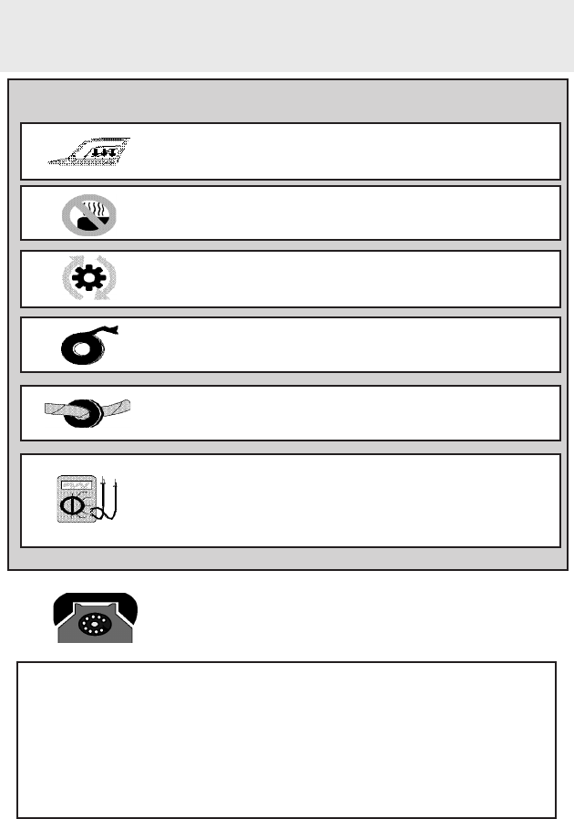
Installation Precautions:
Roll down window to avoid locking keys in vehicle
during installation
Avoid mounting components or routing wires near
hot surfaces
Avoid mounting components or routing wires near
moving parts
Tape or loom wires under hood for protection and
appearance
Use a Digital Multi Meter for testing and verifying
circuits. DO NOT USE A TEST LIGHT, OR
“COMPUTER SAFE PROBE” as these can set off air
bags or damage vehicle computers.
Use grommets when routing wires through metal
surfaces

22014 VOXX Electronics Corporation. All rights reserved.
Security System Layout .............................................................................. 4
I.T.S. Interior Theft Sensor Layout .............................................................5
Setup & Programming - Consumer Mode ................................................. 6
Consumer Mode Types ............................................................................. 6
Consumer Mode Transmitter Programming .............................................. 6
Consumer Mode Feature Programming Bank - Without Transmitters ......6
Consumer Mode Feature Programming Bank - With Transmitters ...........7
Defaulting All Options in the Feature Programming Bank ......................... 7
Consumer Mode Feature Programming Banks ......................................... 8
Setup & Programming - LOT Mode ............................................................ 9
Dealer Lot Mode Description .................................................................... 9
Lot Mode ACM Keypad Transmitter Programming .................................... 9
Lot Mode Feature Programming - Without an ACM Keypad ..................... 9
Lot Mode Feature Programming - With an ACM Keypad ........................ 10
Defaulting the Feature in the Feature Programming Bank ...................... 10
Lot Mode Feature Programming Banks .................................................. 11
Consumer & Lot Mode Types ................................................................... 12
Consumer Mode Types ........................................................................... 12
Lot Mode Types ....................................................................................... 12
Transitioning Between Modes - ACM Keypad ........................................13
Entering into Lot Mode from any Consumer Mode ..................................13
Blue Mode - Keyless Entry Security Upgrade .........................................13
Red Mode - Remote Vehicle Security & Keyless Entry ........................... 14
Green Mode - I.T.S. Interior Theft Sensor ............................................... 14
Yellow Mode - No-Sale ............................................................................ 15
Purple Mode - BCA Borrowed Car Agreement ........................................15
Table of Contents
3PROPLME Install Guide rev A.
Purple Mode - BCA Borrowed Car Agreement ........................................15
Transitioning Between Modes - Short Range Transmitter ..................... 16
Entering into Lot Mode from any Consumer Mode ..................................16
Transitioning into Consumer Mode ..........................................................16
On Board Shock Sensor ........................................................................... 17
Wire Connection Guide .............................................................................18
8 Pin Main Harness .................................................................................19
6 Pin Input / Output Harness ...................................................................21
5 Pin Input Harness ................................................................................. 22
3 Pin Door Lock Harness ........................................................................24
Accessory Connectors ............................................................................. 35
I.T.S. Interior Theft Sensor Functionality .................................................36
I.T.S. Activation ..........................................................................................36
Factory Alarm Trigger .............................................................................. 36
Optional Warn Away ................................................................................ 36
Valet Mode ............................................................................................... 37
I.T.S. Harness Connections ..................................................................... 37
System Power-up Procedure.................................................................... 38
Mounting the Module/Finishing the Installation ..................................... 38
Feature Descriptions ................................................................................. 39
Additional Features ................................................................................... 42
Arm System with Shock Sensor Bypassed ............................................. 42
Attempted Intrusion Identication ............................................................42
Valet Mode ............................................................................................... 42
Deleting Arm / Disarm Notication Chirps ............................................... 42
Dome Light Delay / Theater Lighting Programming ................................ 43
Aftermarket Transmitter Functions..........................................................43
42014 VOXX Electronics Corporation. All rights reserved.
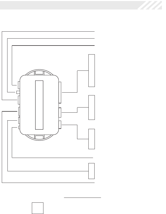
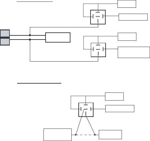
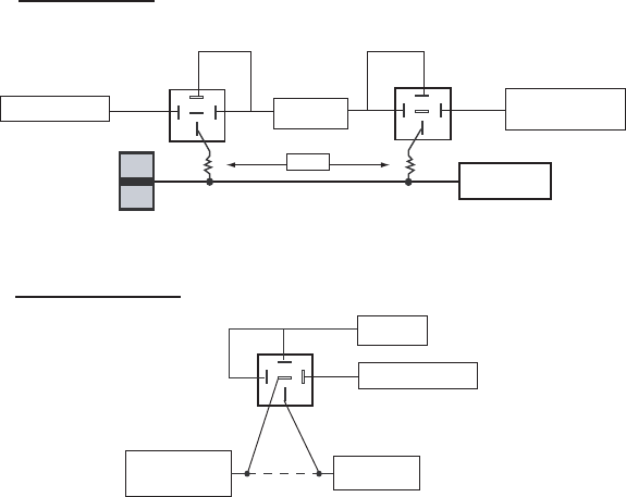
SECURITY SYSTEM LAYOUT
ORANGE 86 - ARMED OUTPUT ( - )
RED 85 - IGNITION ( + )
BLACK 87A - STARTER OUTPUT - MOTOR SIDE
WHITE / BLACK 30 - STARTER OUTPUT - KEY SIDE
STARTER INTERUPT RELAY
RELAY &
HARNESS
#1363731
BLACK GROUND
YELLOW IGNITION
PURPLE DOOR TRIGGER (+)
RED PARKING LIGHT INPUT
WHITE PARKING LIGHT OUTPU
T
BROWN DOOR TRIGGER (-)
RED/WHITE +12 VOLT BATTERY
ORANGE ARMED OUTPUT (-)
OPEN
DK GREEN INSTANT TRIGGER (-)
BLACK/WHITE HORN OUTPUT (-)
LT. GREEN INSTANT TRIGGER (-)
GREEN/WHITE ILLUMINATED ENTRY (-)
DK BLUE TRUNK RELEASE (-)
BLUE TRUNK SHUNT (+)
RED/BLACK DISARM INPUT 2
RED/YELLOW DISARM INPUT
GREEN/BLACK ARM INPUT 2
GREEN ARM INPUT
RED/BLACK 2ND UNLOCK
GREEN UNLOCK OUPUT (-)
RED LOCK OUTPUT (-)
TELEMATIC PORT
DBI PORT
3 Pin 5 Pin 6 Pin 8 Pin
LED / OVERRIDE POD
SHOCK SENSOR DIAL
PROGRAMMING BUTTON
#4120016
#4120019
#4120018
#4120017 #4120015
LOT MODE / CONSUMER SECURITY MODE
5PROPLME Install Guide rev A.
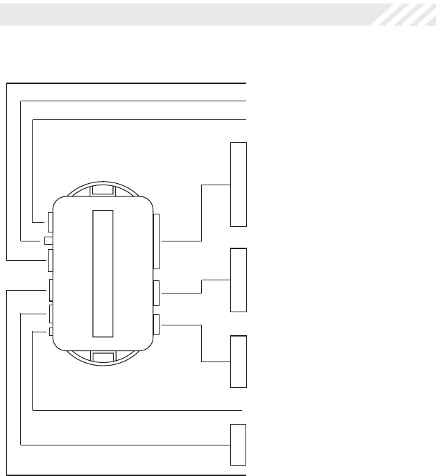
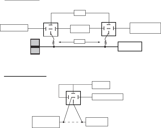
I.T.S. - INTERIOR THEFT SENSOR LAYOUT
BLACK GROUND
YELLOW IGNITION
PURPLE DOOR TRIGGER (+)
RED N/A
WHITE N/A
BROWN DOOR TRIGGER (-)
RED/WHITE +12 VOLT BATTERY
ORANGE N/A
OPEN
DK GREEN N/A
BLACK/WHITE HORN OUTPUT (-)
LT. GREEN N/A
GREEN/WHITE N/A
DK BLUE FACTORY ALARM
TRIGGER (-)
BLUE N/A
RED/BLACK N/A
RED/YELLOW N/A
GREEN/BLACK N/A
GREEN N/A
RED/BLACK N/A
GREEN N/A
RED N/A
TELEMATIC PORT
DBI PORT
3 Pin 5 Pin 6 Pin 8 Pin
LED / OVERRIDE POD
SHOCK SENSOR DIAL
PROGRAMMING BUTTON
#4120016
#4120019
#4120018
#4120017 #4120015
I.T.S. - INTERIOR THERFT SENSOR - MODE
Please note that this layout is simplied for a basic ITS mode installation with the minimum
required connections. If needed, other connections such as the 5 pin arm/disarm harness
may still be utilized to arm or disarm the system using the vehicle’s factory remote transmit-
ters.

62014 VOXX Electronics Corporation. All rights reserved.
SETUP & PROGRAMMING - CONSUMER MODES
Consumer Mode Transmitter Programming
1. Open a door.
2. Turn the ignition ON.
3. Press and release the override button 3 times.
4. The system will chirp 1 time.
5. Press the lock button of each transmitter you wish to program.
6. The system will respond with 1 chirp for each accepted transmitter.
7. Turn the ignition OFF to exit transmitter programming.
8. The system will chirp 2 times to conrm exit.
Note: This system has 1 button programming which programs all channels of the
transmitter to the system at once.
Consumer Mode Feature Programming - Without Transmitters
1. Open a door.
2. Turn the ignition ON.
3. Press and release the override button 3 times, the system will chirp 1 time.
4. Turn the ignition OFF, the system will chirp 2 times.
5. Turn the ignition ON, the system will chirp one time indicating option #1 in the
feature bank. The LED will ash the current setting for the option.
6. Use the override button to scroll through the selections in the feature bank, the
system will chirp to match the feature number.
7. Press the programming button on the module to change the desired feature,
The LED will ash indicating the feature’s setting.
8. Turn the ignition OFF to exit programming, the system will chirp 1 time to
conrm exit.
Consumer Mode Types
Blue Mode - Keyless Entry Security Upgrade System.
Full security utilizing the vehicle’s existing factory remote transmitters.
Red Mode - Remote Vehicle Security & Keyless Entry System.
Full security adding aftermarket remote transmitters.
Green Mode - Interior Theft Sensor.
Add-on impact sensor for vehicles with basic factory security systems and can also
be controlled by either the factory or aftermarket remote transmitters.

7PROPLME Install Guide rev A.
Defaulting All Options in the Feature Programming Bank
1. Open a door.
2. Turn the ignition ON.
3. Press and release the override button 3 times, the system will chirp 1 times
4. Press the programming button on the module, the system will chirp 4 times
indicating the features have been defaulted.
5. Continue on to edit option settings or turn off the ignition to exit programming.
NOTE: This will also default the Dome Light Delay timing if a custom time was set.
Consumer Mode Feature Programming - With Transmitters
1. Open a door.
2. Turn the ignition ON.
3. Press and release the override button 3 times, the system will chirp 1 time.
4. Turn the ignition OFF, the system will chirp 2 times.
5. Turn the ignition ON, the system will chirp one time indicating option #1 in the
feature bank. The LED will ash the current setting for the option.
6. Use the CAR FIND/PANIC button to scroll through the selections in the feature
bank, the system will chirp to match the feature number.
7. Press the LOCK button to change the desired feature. The LED will ash
indicating the feature’s setting.
8. Turn the ignition OFF to exit programming, the system will chirp 1 time to
conrm exit.

82014 VOXX Electronics Corporation. All rights reserved.
Programming Notes:
• The system will remain in programming mode as long as the ignition is on, there is no time limit. To exit
programming turn the IGNITION OFF.
• Changing feature #11 to either of the “ITS Functionality” settings will change the functionality of the entire
system, refer to the “I.T.S. - Interior Theft Sensor Functionality” section of this manual for details.
• Default setting are listed in BOLD.
Consumer Mode - Feature Programming Banks
Feature Bank 1
Transm itter Programming
Feature Bank 2
Consumer Mode Security Control 1 LED Flash 2 LED flash 3 LED Flash 4 LED Flash
1Security Function ON OFFON - Warn
Away Disabled
2Passive Locks PassiveActive
3Silent Choice ON OFF
4Passive/Active Arming PassiveActive
5Siren/Horn SirenHorn
6Door Trigger DelayInstant15 Second
7Arm 2 Input PolarityNegative ( - )Posi tive ( + )
8ChirpsON OFFON - Including
ITS Mode
9Door Lock Output Timing0.9 Seconds 3 Seconds0.9 Sec / Dbl
Pulse Unlock 0.75 Seconds
10 Ignition Controlled Door Locks ALLLock Only Unlock OnlyOFF
11 DK BLUE Wire Output Trunk ITS Function
ITS Function -
Warn Away
Disabled
12 Disarm 2 Input PolarityNegative ( - )Posi tive ( + )
13 Horn Output Timing10mS 16mS 40mS 72mS
14 Real Panic Sound ON OFF
15 ORANGE Wire Output ( - ) Armed
Output
( - ) Disarmed
Output
16 Arming DelayOFF45 Seconds Factory R/S
Option
17 GREEN /WHITE Wire Output Illuminated
EntryFactory Disarm
9PROPLME Install Guide rev A.
SETUP & PROGRAMMING - LOT MODE
Lot Mode ACM Keypad Transmitter Programming
1. Open a door.
2. Turn the ignition ON.
3. Press and release the override button 3 times, the system will chirp 1 time.
4. Enter the desired VEHICLE NUMBER into the ACM keypad and then press the
LOCK button, the system will respond with 1 chirp.
5. Turn the ignition OFF to exit transmitter programming, the system will chirp 2
times to conrm exit.
NOTE: This system has 1 button programming which programs all channels of the
transmitter to the system at once.
When an ACM keypad is programmed to the system, it is automatically transi-
tioned into Lot Mode. Only 1 vehicle number may be learned to the system.
Lot Mode Feature Programming - Without an ACM Keypad
1. Open a door.
2. Turn the ignition ON.
3. Press and release the override button 3 times, the system will chirp 1 time.
4. Turn the ignition OFF, the system will chirp 2 times.
5. Turn the ignition ON, the system will chirp one time indicating option #1 in the
feature bank. The LED will ash the current setting for the option.
6. Use the override button to scroll through the selections in the feature bank, the
system will chirp to match the feature number.
7. Press the programming button on the module to change the desired feature.
The LED will ash indicating the feature’s setting.
8. Turn the ignition OFF to exit programming, the system will chirp 1 time to
conrm exit.
Dealer Lot Mode Description
Lot Mode - Dealer Lot Protection & Keyless Entry System.
Limited security features. Passive arming / locking and starter interrupt utilizing a
dealer ACM Keypad remote transmitter.

10 2014 VOXX Electronics Corporation. All rights reserved.
Lot Mode Feature Programming - With an ACM Keypad
1. Open a door.
2. Turn the ignition ON.
3. Press and release the override button 3 times, the system will chirp 1 time.
4. Turn the ignition OFF, the system will chirp 2 times.
5. Turn the ignition ON, the system will chirp one time indicating option #1 in the
feature bank. The LED will ash the current setting for the option.
6. Use the CAR FIND/PANIC button to scroll through the selections in the feature
bank, the system will chirp to match the feature number.
7. Press the LOCK button to change the desired feature. The LED will ash
indicating the feature’s setting.
8. Turn the ignition OFF to exit programming, the system will chirp 1 time to
conrm exit.
Defaulting All Options in the Feature Programming Bank
1. Open a door.
2. Turn the ignition ON.
3. Press and release the override button 3 times, the system will chirp 1 time.
4. Press the programming button on the module, the system will chirp 4 times
indicating the features have been defaulted.
5. Continue on to edit option settings or turn off the ignition to exit programming.
NOTE: This will also default the Dome Light Delay timing if a custom time was set.

11PROPLME Install Guide rev A.
Programming Notes:
• The system will remain in programming mode as long as the ignition is on, there is no time limit. To exit
programming turn the IGNITION OFF.
• Changing feature #11 to either of the “ITS Functionality” settings will change the functionality of the entire
system, refer to the “I.T.S. - Interior Theft Sensor Functionality” section of this manual for details.
• Default setting are listed in BOLD.
Lot Mode - Feature Programming Banks
Feature Bank 2
Lot Mode Security Control 1 LED Flash 2 LED flash 3 LED Flash 4 LED Flash
1Security Function ON OFFON - Warn
Away Disabled
2Passive Locks Passi ve Active
3Silent ChoiceONOFF
4Passive/Active Arming Passi ve Active
5Siren/Horn SirenHorn
6Door Trigger DelayInstant15 Second
7Arm 2 Input PolarityNegative ( - )Posi tive ( + )
8ChirpsONOFFON - Including
ITS Mode
9Door Lock Output Timing0.9 Seconds 3 Seconds 0.9 Sec / Dbl
Pulse Unlock 0.75 Seconds
10 Ignition Controlled Door Locks ALLLock Only Unlock OnlyOFF
11 DK BLUE Wire Output Trunk ITS Function
ITS Function -
Warn Away
Disabled
12 Disarm 2 Input PolarityNegative ( - )Posi tive ( + )
13 Horn Output Timing10mS16mS 40mS72mS
14 Real Panic Sound ON OFF
15 ORANGE Wire Output ( - ) Armed
Output
( - ) Disarmed
Output
16 Arming Delay OFF45 Seconds Factory R/S
Option
17 GREEN /WHITE Wire Output Illuminated
EntryFactory Disarm
18 Lot Alert OFFON
19 Lot Mode Passive Arming Ti mers
TX Disarm / Ignition 5 / 30 minute1 / 1 minute
Feature Bank 1
Transm itter Programming

12 2014 VOXX Electronics Corporation. All rights reserved.
Consumer Mode Types
Blue Mode - Keyless Entry Security Upgrade System.
Full security utilizing the vehicle’s existing factory remote transmitters. The LED will
ash BLUE in this mode.
Red Mode - Remote Vehicle Security & Keyless Entry System.
Full security adding aftermarket remote transmitters. The LED will ash RED in this
mode.
Green Mode - Interior Theft Sensor.
Add-on impact sensor for vehicles with basic factory security systems and can also
be controlled by either the factory or aftermarket remote transmitters. The LED will
ash GREEN in this mode.
Lot Mode Types
Yellow Mode - No-Sale Mode.
Completely disables the system. Requires a special xture to recover from this mode.
The LED does not ash.
Lot Mode - Dealer Lot Protection & Keyless Entry System.
Limited security features. Passive arming / locking and starter interrupt utilizing a
dealer ACM Keypad remote transmitter. The LED will ash RED in this mode.
BCA Mode - Borrowed Car Agreement.
BCA Mode can also only be accessed while in Lot Mode and puts the Lot Mode
feature into a “valet” status to allow an extended driving period for the customer. BCA
Mode is only accessible through special access ACM Keypads. The LED alternates
between RED and BLUE in this mode.
The system is shipped from the factory in BLUE mode, programming a Remote
transmitter to the system will cause the unit to enter RED mode. The only difference
between the blue and red modes are the addition of the transmitters in red mode. The
GREEN mode can be activated while in the consumer Blue/Red modes by changing the
option in the programming bank.
Transitioning into Lot Mode or from Lot Mode into any of the consumer modes requires
an authorized ACM keypad and is explained in the sections that follow.
CONSUMER & LOT MODE TYPES
13PROPLME Install Guide rev A.
Entering into Lot Mode from any Consumer Mode
1. Turn the ignition ON.
2. Press and release the override button 3 times, the system will chirp 1 time.
3. Enter the desired VEHICLE NUMBER into the ACM keypad and then press the
LOCK button.
4. The system will respond with 1 chirp.
5. Turn the ignition OFF to exit transmitter programming, the system will chirp 2
times to conrm exit.
Notes:
• This system has 1 button programming which programs all channels of the
transmitter to the system at once.
• Use of an ACM keypad is required.
• Once an ACM keypad is programmed to the system, it is automatically
transitioned into Lot Mode. Only 1 vehicle number may be learned to the
system.
• When in lot mode, a consumer remote can not be programmed to the system
until it is transitioned to consumer mode.
• All programming features will be defaulted to the factory default settings.
TRANSITIONING BETWEEN MODES - ACM KEYPAD
Blue Mode - Keyless Entry Security Upgrade
1. Open a vehicle door.
2. Enter the vehicle number into an ACM keypad.
3. Press the UNLOCK button.
4. Press and release the TRANS button.
5. Press and release the “BLUE” button.
6. The LED will ash blue 1 time and the system will chirp 3 times.
7. Close the vehicle’s door.
Notes:
• The ACM keypad must be authorized for transitioning.
• Factory Keyless Upgrade Mode enables all of the device’s security
functionality and utilizes the factory remote transmitters.

14 2014 VOXX Electronics Corporation. All rights reserved.
Green Mode - I.T.S. Interior Theft Sensor
1. Open a vehicle door.
2. Enter the vehicle number into an ACM keypad.
3. Press the UNLOCK button.
4. Press and release the TRANS button.
5. Press and release the “GREEN” button.
6. Close the vehicle’s door.
Notes:
• The ACM keypad must be authorized for transitioning.
• I.T.S. mode enables the shock sensor only of this device for applications in a
vehicle equipped with a factory security system.
Red Mode - Remote Vehicle Security & Keyless Entry
1. Open a vehicle door.
2. Enter the vehicle number into an ACM keypad.
3. Press the UNLOCK button.
4. Press and release the TRANS button.
5. Press and release the “RED” button.
6. The LED will ash red 1 time and the system will chirp 3 times.
7. Within 5 seconds program the aftermarket transmitter by pressing the lock but
ton of each transmitter you wish to program.
8. Close the vehicle’s door.
Notes:
• The ACM keypad must be authorized for transitioning.
• If no remotes are programmed during step 7, the system will automatically
transition into the Factory Keyless Entry Security Upgrade Mode - BLUE
• Security with Transmitters Mode enables all of the device’s security
functionality by use of aftermarket transmitters.

15PROPLME Install Guide rev A.
Yellow Mode - No-Sale
1. Open a vehicle door.
2. Enter the vehicle number into an ACM keypad.
3. Press the UNLOCK button.
4. Press and release the TRANS button.
5. Press and release the “YELLOW” button.
6. Close the vehicle’s door.
Notes:
• The ACM keypad must be authorized for transitioning.
• No-Sale mode disables all functionality of the unit and requires a programming
jig to recover the module from this mode. This mode is typically only used
when there is a no-sale of the product and you are not removing the system
from the vehicle.
Purple Mode - B.C.A. Borrowed Car Agreement
1. Open a vehicle door.
2. Enter the vehicle number into an ACM keypad.
3. Press the UNLOCK button.
4. Press and release the TRANS button.
5. Press and release the “PURPLE” button.
6. Close the vehicle’s door.
Notes:
• The ACM keypad must be authorized for BCA transitioning.
• Lot Mode and puts the Lot Mode feature into a “valet” status to allow an
extended driving period for the customer. Note that the is still in Lot Mode.
Exit B.C.A. Mode
Exiting B.C.A. Mode returns the unit to an active Lot Mode state with the original vehicle
stock number entered when Lot Mode was activated.
1. Open a vehicle door.
2. Turn ON the vehicle’s ignition.
3. Press and Hold the valet button for 3 seconds. The unit will exit BCA Mode.

16 2014 VOXX Electronics Corporation. All rights reserved.
Transitioning into Consumer Mode
1. Open a vehicle door.
2. Press and hold button 2 of the short range transmitter until the system chirps
3 times.
3. Again press and hold button 2 of the short range transmitter until the system
chirps 3 times.
4. Within 5 seconds program a consumer remote. If no remotes are programmed
in the 5 second window, the system will default to the factory keyless upgrade
setting which uses the factory remote controls to arm and disarm the system.
Notes:
• Programming features 1-4 will be defaulted to the factory default settings,
programming features 5-13 will retain any changes that have been made.
Entering into Lot Mode from any Consumer Mode
1. Turn the ignition ON.
2. Press and release the override button 3 times, the system will chirp 1 time.
3. Press button 1 of the short range transmitter, the system will chirp 1 time.
4. Turn the ignition OFF to exit transmitter programming.
5. The system will chirp 2 times to conrm exit.
Notes:
• This system has 1 button programming which programs all channels of the
transmitter to the system at once.
• When in lot mode, a consumer remote can not be programmed to the system
until it is transitioned to consumer mode.
• All programming features will be defaulted to the factory default settings.
TRANSITIONING BETWEEN MODES - SHORT RANGE
TRANSMITTER

17PROPLME Install Guide rev A.
ON BOARD SHOCK SENSOR
Adjusting and Testing the Shock Sensor
It is recommended that you test the shock sensor after making any adjustments to the
sensitivity.
The shock sensor has two levels of protection, one to detect light impacts to the vehicle
and one to detect larger impacts. Adjusting the shock sensor’s sensitivity dial will adjust
both light and full triggers zones simultaneously. If the light impact zone, also referred to
as warn-away, can be turned completely off in option programming.
To test the shock sensor, arm the system and wait 6 - 10 seconds for the zone to stabi-
lize, then rmly strike the vehicle being careful not to damage it. Repeat if necessary.
• Increase sensitivity by turning the adjustment dial clockwise.
• Decrease sensitivity by turning the adjustment dial counter clockwise.
When using the aftermarket remote transmitter the shock sensor can be temporarily
bypassed when for one arm cycle by pressing Trunk or Find button within 5 seconds of
pressing the Lock button.
18 2014 VOXX Electronics Corporation. All rights reserved.
1BLACKGROUND
2YELLOWIGNITION ( + )
3PURPLE DOOR TRIGGER INPUT ( + )
4REDPARKING LIGHT INPUT
5WHITEPARKING LIGHT OUTPUT
6BROWNDOOR TRIGGER INPUT ( - )
7RED / WHITEBATTERY 12V ( + )
8ORANGE ARMED OUTPUT ( - )
8 PIN MAIN
1BLUE TRUNK SHUNT INPUT ( + )
2RED / BLACKDISARM INPUT 2
3RED/YELLOW DISARM INPUT
4GREEN / BLACK ARM INPUT 2
5GREEN ARM INPUT
5 PIN INPUT
1OPEN
2DK GREEN INSTANT TRIGGER INPUT ( - )
3BLACK / WHITEHORN OUTPUT ( - )
4LT GREEN INSTANT TRIGGER INPUT ( - )
5GREEN / WHITEILLUMINATE D ENTRY OUTPUT ( - )
6DK BLUETRUNK RELEASE OUTPUT ( - )
6 PIN INPUT / OUTPUT
8 PIN MAIN HARNESS
6 PIN INPUT / OUTPUT HARNESS
5 PIN INPUT HARNESS
19PROPLME Install Guide rev A.
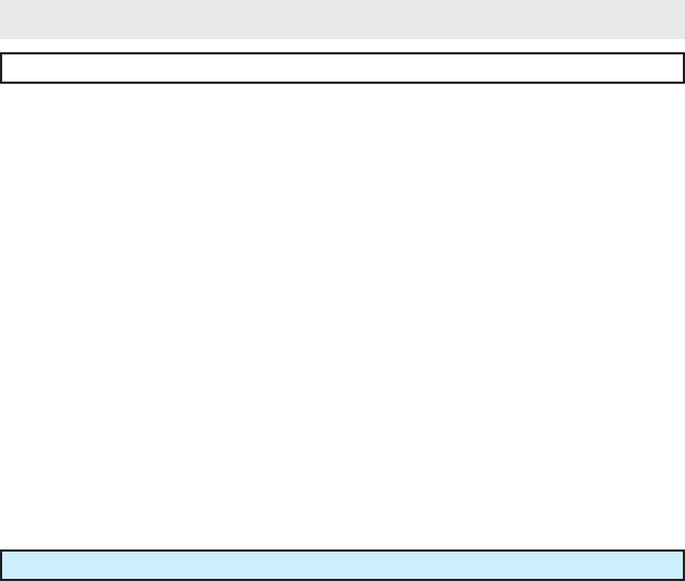
8 PIN MAIN HARNESS
1 BLACK Chassis Ground Source ( - )
Connect the BLACK wire to a solid chassis ground point using a ring terminal and self
tapping screw (not supplied). Scrape away paint from the grounding point to ensure a
good connection. The recommended grounding point is a metal surface in the driver’s
side kick panel area.
NOTE: Do not ground the BLACK wire with any other vehicle components.
1RED / BLACK2ND UNLOCK OUTPUT ( - )
2GREEN UNLOCK OUTPUT ( - )
3REDLOCK OUTPUT ( - )
3 PIN
LOCK
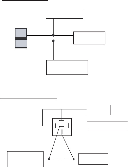
86 ORANGE ARMED OUTPUT ( - )
85 REDIGNITION ( + )
87aBLACKSTA RTER OUTPUT - MOTOR SIDE
87 WHITE / BLACK STARTER OUTPUT - KEY SIDE
STARTER
INTERUPT
RELAY
3 PIN LOCK HARNESS
STARTER INTERRUPT HARNESS
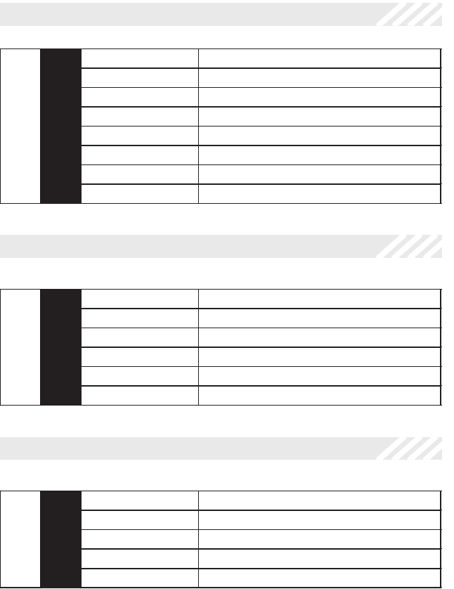
2 YELLOW Ignition ( + )
Locate the vehicle’s ignition wire at the ignition switch.
Verication:This wire registers voltage when the key is turned to the ON (or
RUN) position. The voltage does not drop out when the key is turned to the START
(or CRANK) position.
Connect the YELLOW wire to the vehicle’s Ignition wire.

20 2014 VOXX Electronics Corporation. All rights reserved.
3 PURPLE Door Trigger Input ( + )
Locate the vehicle’s dome light or door pin switch wire.
Verication:Thiswirewillregisterpositivevoltage(POS)whenthedoorisopened
and the interior light is on. This wire will register ground or “0” Volts when the door is
closed and the interior light is off.
Connect the PURPLE wire to the vehicle’s positive door input wire(s).
NOTE: Certain vehicles may require multiple connections. Refer to vehicle application
guide
4 RED Parking Light Polarity
5 WHITE Parking Light Output ( + / - )
Locate the vehicle’s parking light wire at the vehicle light switch.
Verication:This wire will register positive voltage or ground when the vehicle parking
light switch is turned to the ON position.
These wires are the COMMON and NORMALLY OPEN contacts of the on-board parking
light relay. If the vehicle’s parking lights are a +12 volt switched system, connect
the RED wire to a fused +12 volt battery source, and connect the WHITE wire to the
vehicle’s parking light wire. If the vehicle’s parking lights are a chassis ground switched
system, connect the RED wire to a chassis ground source, and connect the WHITE wire
to the vehicle’s parking light wire.
6 BROWN Door Trigger Input ( - )
Locate the vehicle’s dome light or door pin switch wire.
Verication:Thiswirewillregisterground(NEG)whenthedoorisopenedandthe
interior light is on. This wire will register positive voltage when the door is closed and
the interior light is off.
Connect the BROWN wire to the vehicle’s negative door input wire(s).
NOTE: Certain vehicles may require multiple connections. Refer to vehicle application
guide

21PROPLME Install Guide rev A.
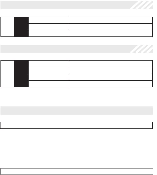
7 RED / WHITE 12 Volt Battery Input ( + )
Locate 1 of the vehicle’s constant 12 Volt battery wires at the ignition switch.
Verication:This wire will register voltage in all positions of the ignition switch.
Connect the RED/WHITE wire to the constant 12 Volt battery wire.
NOTE: Remove the in-line fuse until all connections are made.
8 ORANGE Armed Output ( - ) 500mA
This wire will show ground when the system is armed. This wire is used for controlling a
starter interrupt relay, window modules or other additional sensors.
NOTE: Can also be used as a Disarmed Output ( - ) for a normally open starter kill.
Setting must be changed in option programming.
6 PIN INPUT / OUTPUT HARNESS
2 DK. GREEN Instant Trigger Input ( - )
This wire is a ground input for an external sensor, trunk pin or secondary pin switch.
Verication:Thiswire,whenconnected,willtriggerthesecuritysystem.
3 BLACK / WHITE Horn Output ( - ) 300mA
Locate the vehicle’s horn wire at the steering column.
Verication:This wire will register at positive voltage and register ground when the
horn switch is pressed.
Connect the BLACK/WHITE wire to the vehicle’s horn wire.
1 OPEN No Wire Connection

22 2014 VOXX Electronics Corporation. All rights reserved.
5 GREEN / WHITE Illuminated Entry Output ( - ) 200mA
This wire provides a 200mA output for 30 seconds when the system is disarmed and a
continuous output when the system is triggered.
Verication:This wire will register positive voltage or ground when the vehicle’s dome
light is turned ON.
Locate the vehicle’s dome light or pin switch wire.
6 DK. BLUE Trunk Release Output ( - ) 300mA
This wire provides a 500mA negative output capable of driving relays. For Control of
optional accessories such as trunk release.
• To Activate press and hold UNLOCK for 2 seconds.
Verication:This wire will register either positive voltage or ground when the trunk
release is activated.
Locate the vehicle’s trunk release wire at the trunk release switch.
5 PIN INPUT HARNESS
1 BLUE Trunk Shunt Input ( + )
This Wire, when activated, will suspend all security zones from triggering the system until
5 second after the shunt input OR the last trigger input clears.
4 LT. GREEN Instant Trigger Input ( - )
Install the supplied Hood Pin Switch and connect to the LT GREEN wire.
Verication:Thiswirewhenconnectedwillregistergroundwhenthevehicle’shoodis
opened.
Connect the LT GREEN wire to the hood pin.
NOTE: Be sure to loom the wire, and seal the grommet.

23PROPLME Install Guide rev A.
3 RED / YELLOW Disarm Input
This wire will DISARM the security system when a ( + ) pulse is applied to it from an
external device such as the vehicle’s factory unlock motor wire.
2 RED / BLACK Disarm Input 2
This wire will prevent the system from disarming the security system when a POS or
NEG pulse is applied to it from an external device. This will prevent the system from
disarming if it is pulsed at the same time as the RED (Disarm Input) wire.
For example: To prevent the system from disarming from the switch on the door
connect this wire to the unlock switch or passenger unlock motor wire
NOTE: Only required if using the factory keyless entry transmitter to ARM/DISARM this
system.
5 GREEN Arm Input
This wire will ARM the security system when a ( + ) pulse is applied to it from an external
device such as the vehicle’s factory lock motor wire.
4 GREEN / BLACK Arm Input 2
This wire will prevent the system from arming the security system when a POS or
NEG pulse is applied to it from an external device. This will prevent the system from
disarming if it is pulsed at the same time as the GREEN (Arm Input) wire.
For example: To prevent the system from arming from the switch on the door
connect this wire to the lock switch or passenger lock motor wire
NOTE: Only required if using the factory keyless entry transmitter to ARM/DISARM this
system.

24 2014 VOXX Electronics Corporation. All rights reserved.
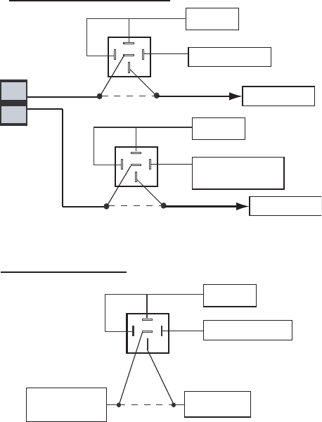
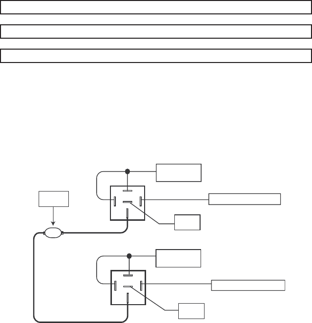
3 PIN DOOR LOCK HARNESS
1 RED / BLACK 2nd Unlock Output ( - ) 200mA
2 GREEN Unlock Output ( - ) 200mA
3 Red Lock Output ( - ) 200mA
Negative Switching and Negative Switching with 2-step unlock feature:
All Door Lock and Unlock: Locate the lock / unlock wire at the vehicle’s lock / unlock
switch.
Verication: These wires will register ground when the lock and unlock switches are
activated.
Driver’s Door Unlock: Locate the unlock motor wire directly from the actuator inside
the driver’s door.
Verication:This wire will rest at ground and register positive voltage when the
driver’s door is unlocked.
Connect the RED and GREEN or RED/BLACK wires shown in the diagram below.
NOTE: When adding the 2 step unlock feature the RED/BLACK 2nd door unlock wire
will be used to unlock all vehicle doors on the second press of unlock. An additional
SPDT relay (not supplied) is required. Connect the relay as shown in the diagram
below to unlock the driver’s door on the rst press of unlock.
25PROPLME Install Guide rev A.
Lock
Unlock
87
87a
86 85
30
Vehicle Door Lock
Control Relays
RED (-) Lock Output
GREEN (-) Unlock Output or
RED/BLACK 2nd Unlock
Output for 2 Step Unlock
For 2 Step Unlock:
Fused +12 Volt
Battery Souce
GREEN (-) Unlock Output
From Keyless Entry
Module or Door
Unlock Relay
Drivers Door
Unlock Motor Wire
X
Cut
Negative Locks:

26 2014 VOXX Electronics Corporation. All rights reserved.
1 RED / BLACK 2nd Unlock Output ( - ) 200mA
2 GREEN Unlock Output ( - ) 200mA
3 Red Lock Output ( - ) 200mA
Positive Switching and Positive Switching with 2-step unlock feature:
All Door Lock and Unlock: Locate the lock / unlock wire at the vehicle’s lock / unlock
switch.
Verication: These wires will register positive voltage when the lock and unlock
switches are activated.
Driver’s Door Unlock: Locate the unlock motor wire directly from the actuator inside
the driver’s door.
Verication:This wire will rest at ground and register positive voltage when the
driver’s door is unlocked.
Connect the RED and GREEN or RED/BLACK wires shown in the diagram below.
NOTE: When adding the 2 step unlock feature the RED/BLACK 2nd door unlock wire will
be used to unlock all vehicle doors on the second press of unlock. Two additional
SPDT relays (not supplied) are required. Connect the relays as shown in the
diagram below to unlock the driver’s door on the rst press of unlock.
27PROPLME Install Guide rev A.
Lock
Unlock
87
87a
86 85
30
87
87a
86 85
30
87
87a
86 85
30
Vehicle Door Lock
Control Relays
Fused +12 Volt
Battery Souce
Fused +12 Volt
Battery Souce
RED (-) Lock Output
GREEN (-) Unlock Output or
RED/BLACK 2nd Unlock
Output for 2 Step Unlock
For 2 Step Unlock:
Fused +12 Volt
Battery Souce
GREEN (-) Unlock Output
From Keyless Entry
Module or Door
Unlock Relay
Drivers Door
Unlock Motor Wire
X
Cut
Positive Locks:

28 2014 VOXX Electronics Corporation. All rights reserved.
1 RED / BLACK 2nd Unlock Output ( - ) 200mA
2 GREEN Unlock Output ( - ) 200mA
3 Red Lock Output ( - ) 200mA
One Wire Negative Multiplexed and One Wire Negative Multiplexed with 2 step
Unlock Feature:
All Door Lock and Unlock: Locate the lock / unlock wire at the vehicle’s lock / unlock
switch.
Verication: This wire will show variable ground when the switch is activated. Please
consult the Vehicle Wire Color and Location Chart for specic resistor values for
the vehicle.
Driver’s Door Unlock: Locate the unlock motor wire directly from the actuator inside
the driver’s door.
Verication:This wire will rest at ground and register positive voltage when the
driver’s door is unlocked.
Connect the RED and GREEN or RED/BLACK wires shown in the diagram below
using (2) SPDT relays (not supplied).
NOTE: When adding the 2 step unlock feature the RED/BLACK 2nd door unlock wire
will be used to unlock all vehicle doors on the second press of unlock. An additional
SPDT relay (not supplied) is required. Connect the relay as shown in the diagram
below to unlock the driver’s door on the rst press of unlock.
29PROPLME Install Guide rev A.
Lock
Unlock
87
87a
86 85
30
Vehicle Door Lock
Control Relays
RED (-) Lock Output
GREEN (-) Unlock Output or
RED/BLACK 2nd Unlock
Output for 2 Step Unlock
For 2 Step Unlock:
Fused +12 Volt
Battery Souce
GREEN (-) Unlock Output
From Keyless Entry
Module or Door
Unlock Relay
Drivers Door
Unlock Motor Wire
X
Cut
Multiplex Locks:
87
87a
86
30
87
87a
86
30
85 85
Fused +12 Volt
Battery Source
Ground
Resistor

30 2014 VOXX Electronics Corporation. All rights reserved.
1 RED / BLACK 2nd Unlock Output ( - ) 200mA
2 GREEN Unlock Output ( - ) 200mA
3 Red Lock Output ( - ) 200mA
One Wire Positive Multiplexed and One Wire Multiplexed With 2-step Unlock
Feature:
All Door Lock and Unlock: Locate the lock / unlock wire at the vehicle’s lock / unlock
switch.
Verication: This wire will show variable positive voltage when the switch is activated.
Please consult the Vehicle Wire Color and Location Chart for specic resistor
values for your vehicle.
Driver’s Door Unlock: Locate the unlock motor wire directly from the actuator inside
the driver’s door.
Verication:This wire will rest at ground and register positive voltage when the
driver’s door is unlocked.
Connect the RED and GREEN or RED/BLACK wires shown in the diagram below
using (2) SPDT relays (not supplied).
NOTE: When adding the 2 step unlock feature the RED/BLACK 2nd door unlock wire
will be used to unlock all vehicle doors on the second press of unlock. An additional
SPDT relay (not supplied) is required. Connect the relay as shown in the diagram
below to unlock the driver’s door on the rst press of unlock.
31PROPLME Install Guide rev A.
Lock
Unlock
87
87a
86 85
30
Vehicle Door Lock
Control Relays
RED (-) Lock Output
GREEN (-) Unlock Output or
RED/BLACK 2nd Unlock
Output for 2 Step Unlock
For 2 Step Unlock:
Fused +12 Volt
Battery Souce
GREEN (-) Unlock Output
From Keyless Entry
Module or Door
Unlock Relay
Drivers Door
Unlock Motor Wire
X
Cut
Multiplex Locks:
87
87a
86
30
87
87a
86
30
85 85
Fused +12 Volt
Battery Source
Resistor

32 2014 VOXX Electronics Corporation. All rights reserved.
1 RED / BLACK 2nd Unlock Output ( - ) 200mA
2 GREEN Unlock Output ( - ) 200mA
3 Red Lock Output ( - ) 200mA
Reverse Polarity (5-Wire Door locks) and Reverse Polarity with 2-step Unlock:
All Door Lock and Unlock: Locate the lock / unlock wire at the vehicle’s lock / unlock
switch.
Verication: These wires will rest at ground and register positive voltage when the
lock and unlock switches are activated.
Driver’s Door Unlock: Locate the unlock motor wire directly from the actuator inside
the driver’s door.
Verication:This wire will rest at ground and register positive voltage when the
driver’s door is unlocked.
Connect the RED and GREEN or RED/BLACK wires shown in the diagram below
using (2) SPDT relays (not supplied).
NOTE: When adding the 2 step unlock feature the RED/BLACK 2nd door unlock wire
will be used to unlock all vehicle doors on the second press of unlock. An additional
SPDT relay (not supplied) is required. Connect the relays as shown in the diagram
below to unlock the driver’s door on the rst press of unlock.
33PROPLME Install Guide rev A.
Lock
Unlock
87
87a
86 85
30
87
87a
86 85
30
87
87a
86 85
30
Fused +12 Volt
Battery Souce
Fused +12 Volt
Battery Souce
RED (-) Lock Output
GREEN (-) Unlock Output or
RED/BLACK 2nd Unlock
Output for 2 Step Unlock
For 2 Step Unlock:
Fused +12 Volt
Battery Souce
GREEN (-) Unlock Output
From Keyless Entry
Module or Door
Unlock Relay
Drivers Door
Unlock Motor Wire
X
Cut
Reverse Polarity Locks:
X
Cut
X
Cut
To Door Lock Motor
To Door Lock Motor
34 2014 VOXX Electronics Corporation. All rights reserved.
1 RED / BLACK 2nd Unlock Output ( - ) 200mA
2 GREEN Unlock Output ( - ) 200mA
3 Red Lock Output ( - ) 200mA
Adding Door Actuators:
After installing door actuators, (not supplied). Connect the RED and GREEN wires
shown in the diagram below using (2) SPDT relays (not supplied).
30
87
87a
86 85
Fused +12 Volt
Battery Source
Door Lock
Actuator
30
87
87a
86 85
Chassis
Ground
Chassis
Ground
RED (-) Lock Output
GREEN (-) Unlock Output
Fused +12 Volt
Battery Source
M
35PROPLME Install Guide rev A.
ACCESSORY CONNECTORS
6 Pin LED / Override Pod
The status LED / override button should be mounted in a visible and easily accessible
location on the driver’s dashboard area. Route the harness and plug the 6 pin connector
into the module.
4 Pin Telematic Port
This 4 pin port is used for connecting the telematic accessories such as Car Connection,
CarLink, or PursuiTrak.
4 Pin DBI - Data Bus Interface Port
This 4 pin port is used for Flashlogic Door Lock and Transponder Databus Interfaces
to communicate with the vehicle’s Databus. When using the DBI port to control the
Flashlogic Door Lock and Transponder Interface modules the following options may be
available. Please refer to the D2D (Data to Data) function list available per vehicle on the
tech service web site.
Door Trigger Trunk/Hatch Open
Keyless Entry Control Dome Light Supervision
Factory Alarm Arm / Disarm Manual Arm / Disarm Inputs (factory
keyless controls system)
36 2014 VOXX Electronics Corporation. All rights reserved.
Factory Alarm Trigger
The ITS Factory Alarm Trigger is active 30 seconds after the ignition is turned off and
the factory alarm has been set. When a heavy impact is detected the ITS will pulse the
vehicle’s door trigger wire to active the factory alarm.
Optional Warn Away
The optional Warn-Away Trigger is active 30 seconds after the ignition key is turned off
and the dome light shuts off after exiting the vehicle. When a light impact is detected the
system will briey honk the vehicles horn. If at any time a door is opened (dome light “on”),
the Warn-Away Trigger will be bypassed until the ignition key is cycled “ON” and “OFF”.
This feature prevents the Warn-Away chirps of the vehicle’s horn when the customer/user
enters the vehicle. The Warn-Away Trigger will reactivate when the ignition key is cycled
“ON” and “OFF” again.
I.T.S. ACTIVATION
I.T.S. - INTERIOR THEFT SENSOR FUNCTIONALITY
I.T.S. - Interior Theft Sensor Introduction
The system may be used as an I.T.S. (Interior Theft Sensor) and when doing so it is de-
signed to honk the horn if a light impact is detected or trigger the vehicle’s factory security
system if a harder impact is detected.
Note: The vehicle MUST have a factory security system that is triggered by opening the
vehicle’s door.
Option #11 must be changed in the feature programming bank for the system to function
as the I.T.S.. This will also happen automatically when transitioning from Lot mode to Green
mode using an ACM Keypad.
The factory keyless remote can also be used to arm/disarm the I.T.S. sensor as long as
the standard arm & disarm input wires are connected to the vehicle. You may also program
an aftermarket remote transmitter to the unit as well.

37PROPLME Install Guide rev A.
I.T.S. Harness Connections
DK BLUE - Factory Alarm Trigger: Connect this to a wire which triggers the vehicle’s
factory alarm system such as the door ajar, hood or trunk wire.
PURPLE and BROWN - Door Inputs ( + / - ): Connect one of these wires to the vehicle’s
dome light wire.
RED/WHITE - +12 Volt Input: Connect this wire to constant +12 volt source.
BLACK - Ground Input: Connect this wire to chassis ground.
YELLOW - Accessory Input: Connect this wire to +12 volt accessory source.
BLACK/WHITE - Warn Away Horn Output: Connect this wire to the vehicle’s horn wire.
NOTES:
The ITS uses the PURPLE or BROWN (Door Input) to DISARM the optional Warn-Away
feature. The PURPLE or BROWN must sense all of the doors for the ITS to DISARM
properly. It is recommended to only use the Warn-Away feature with vehicle’s that have an
“ALL” door trigger output in the vehicle.
Valet Mode
Valet Mode deactivates both the optional Warn-Away and Factory Alarm Trigger.
To turn Valet Mode ON:
Turn the ignition key to the ON position and press and hold the valet button until the LED
turns on solid.
To turn Valet Mode OFF:
Turn the ignition key to the ON position and press and hold the valet button until the LED
turns off.

38 2014 VOXX Electronics Corporation. All rights reserved.
SYSTEM POWER-UP PROCEDURE
1. After all connections are complete, turn the vehicle’s ignition key to the ON
position
2. Insert the 5 Amp fuse into the respective fuseholder.
3. Turn the ignition key to the OFF position.
MOUNTING THE MODULE / FINISHING INSTALLATION
Mount the module to a brace or wire harness under the dash. The module and
harnesses must be clear of moving parts.
Installation Complete.

39PROPLME Install Guide rev A.
Feature Bank 1, 3 Chirps
1 - Security Function: Controls security functionality - ON / OFF. Note: In Lot Mode all
security triggers will be ignored no matter what setting is selected.
ON - Full security functionality.
OFF - The security system does not trigger. All other convenience
features operate as normal.
ON, Warn Away Disabled - Full security functionality with the warn-away
function of the shock sensor disabled.
2 - Passive Locks: Determines manual or automatic locking of the vehicle’s doors.
Passive - Automatically locks the vehicle’s doors 1 minute after the last door is
closed.
Active - Requires use of the transmitter to lock the vehicle’s doors.
3 - Silent Choice: Controls when the normal arm/disarm chirps of the security system
will sound. (Feature #8 must be ON)
ON - Silent arming/disarming upon rst press of lock/unlock, pressing lock/
unlock a second time will activate the arm/disarm chirps respectively. The
system will only sound the arm/disarm chirps upon a second press of the lock/
unlock buttons.
OFF - normal arm/disarm chirps upon the rst press of lock/unlock.
4 - Passive/Active Arming: Determines manual or automatic locking of the vehicle’s
doors.
Passive - Automatically arms the security system 1 minute after the last door is
closed.
Active - Requires use of the transmitter to arm the security system.
5 - Siren / Horn: This feature selects the output type for the BLACK/WHITE wire during
the security trigger cycle.
Siren - 30 second constant output.
Horn – 30 second pulsed output.
6 - Door Trigger Delay: Selectable instant or delayed trigger cycle when security is trig-
gered by the door input.
Instant – Door input instantly triggers alarm sequence.
15 Second - Door input delays triggering the alarm sequence for 15 seconds.
7 - Arm Input 2 Polarity: Select the input polarity as positive or negative.
FEATURE DESCRIPTIONS
40 2014 VOXX Electronics Corporation. All rights reserved.
8 - Arm/Disarm Chirps: Controls the normal Arm / Disarm chirps. NOTE: This feature
must be ON to use system chirps even with the silent choice feature enabled
ON - Arm / Disarm chirps function as normal.
OFF - All Arm / Disarm chirps are disabled.
ON Including ITS Mode - Arm / Disarm chirps function as normal including
when in ITS Mode.
9 - Door Lock Output Timing: Controls the timing of the RED and GREEN lock output
wires.
0.9 Second - Single 0.9 second lock pulse, single 0.9 second unlock pulse.
3 Seconds - Single 3 second lock pulse, single 3 second unlock pulse.
0.9 Second Lock, Double Pulse Unlock - Single 0.9 second lock pulse, double
0.9 second unlock pulse.
0.75 Second - Single 0.75 second lock pulse, single 0.75 second unlock pulse.
10 - Ignition Controlled Locks: Control of door locks when the ignition is cycled ON or
OFF.
All (Lock & Unlock) - Doors lock when ignition is turned on and unlock when
ignition is turned off.
Lock Only - Doors lock when ignition is turned on
Unlock Only - Doors unlock when ignition is turned off.
OFF - Door locks not activated by ignition.
11 - DK BLUE Wire Output: This feature controls the type of output for the DK BLUE
wire. Setting this feature to ITS Function will change the functionality of the entire sys-
tem, refer to ITS functionality of the install guide.
Trunk - 1 second pulsed output.
ITS Function - ITS function, warn-away and full trigger.
ITS Function, Warn Away Disabled - ITS function with full trigger only
12 - Disarm Input 2 Polarity: Select the input polarity as positive or negative.
13 - Horn Output Timing: Control the minimum horn pulse time in milliseconds, some
vehicle will require a longer pulse to activate the factory horn.
10mS 16mS 30mS 40mS 72mS
14 - Real Panic Sound: Controls the horn output when the system is triggered.
ON - Randomized horn honks when panic/security is triggered.
OFF - Standard pattern horn honks when panic/security is triggered.
41PROPLME Install Guide rev A.
15 - Orange Wire Output: Controls the output of the orange wire. This wire will either
supply a ( - ) output when armed OR disarmed.
( - ) Armed Output - Supplies a constant negative out while the system is
armed
( - ) Disarmed Output - Supplies a constant negative out while the system is
disarmed
16 - Arming Delay: Control the type of arming; standard, delayed or armed with vehicle
remote started.
OFF - No delay when arming, normal security functionality.
45 Seconds - Delays the arming process for 45 seconds when armed using
the ARM/DISARM INPUTS, during this time the system will be disarmed if the
ignition is turned ON. No delay is added if using an aftermarket transmitter to
arm the system
Factory R/S Option - For use with vehicles with a FACTORY INSTALLED
Remote Start. If the ignition comes on within 6 seconds of arming the system,
the system will ignore ALL security inputs until 5 seconds after ignition clears
OR any remaining inputs clear after ignition has cleared.
17 - GREEN/WHITE Output Wire: Controls the GREEN/WHITE output type.
Illuminated Entry - Supplies a constant output for 1 minute.
Factory Disarm - Single 1 second puled output upon disarming the system.
18 - Lot Alert: Available in Lot Mode only - Toggle Lot Mode notication chirps ON/OFF.
OFF - No notication chirps
ON - 5 short low volume chirps each time the ignition is turn ON.
19 - Lot Mode Passive Arming Timers; TX Disarm / Ignition: Available in Lot Mode
only - Change the passive arming timers when the system is unlocked or the ignition is
turned on.
5 / 30 Minute - 5 minute timer when doors have been unlocked / 30 minute
timer after the ignition has been turned OFF.
1 / 1 Minute - 1 minute timer when doors have been unlocked / 1 minute timer
after the ignition has been turned OFF.

42 2014 VOXX Electronics Corporation. All rights reserved.
ADDITIONAL FEATURES
Arm System with Shock Senor Bypassed (Aftermarket TX only)
1. Press Lock button to arm system
2. Within 5 seconds press the Trunk OR Find/Panic button. Parking Lights/Horn
will ash/chirp 2 times.
AttemptedIntrusionIdentication
Pressing UNLOCK after a full 30 second trigger cycle has completed, the horn will honk
4 times and the LED will ash a number of times to indicate which input triggered the
alarm. Turning on the ignition or pressing the valet/override button will reset the LED
ashes, pressing the valet/override button will also honk the horn to match the LED
ashes before it is reset.
Number of ashes:
1 - Interior Theft Sensor (Shock Sensor)
2 - Door Input
3 - Hood Input
4 - Trunk Input
5 - Ignition
Valet Mode - Consumer Modes Only
To engage valet mode:
1. Turn the ignition key ON.
2. Press and hold the valet button until the LED status light turns on solid
indicating that the system is in valet mode.
3. Release the valet button.
4. When valet mode is activated all security functions will be disabled.
To disengage valet mode:
1. Turn the ignition key ON.
2. Press and hold the valet button until the LED status light turns off indicating
that the system has exited valet mode.
DeletingArm/Disarmnoticationchirps
1. Turn the ignition ON then OFF.
2. Press and release the valet button 3 times. The system will respond with 1
chirp for ON or 2 chirps for OFF.

43PROPLME Install Guide rev A.
System Function Lot Mode
ACM Keypad TX
Consumer Mode
Aftermarket TX Operation Method
Lock Doors / Arm System Lock Lock Press and Release
Unlock / Disarm
(consumer Mode)Unlock Press and Release
Unlock / Unlock 2 / Disarm
(Lot Mode) Unlock Press and Release
2 Step UnlockUnlockPress and Release 2 times (within 5 sec)
Unlock & Unlock 2 activate at the same time
Trunk TrunkPush and Hold (2 Sec)
Trunk / DisarmUnlockPush and Hold (2 Sec)
Car Finder (Progressive)Find/PanicFind/Panic
Press and Release, 3 volume levels for Chirp -
1st press - Low
(within 3 sec of 1st press) 2nd press - Medium
(within 3 sec of 2nd press) 3rd press - Loud
PanicFind/PanicFind/PanicPush and Hold (1 Sec)
Shock Bypass
Lock - Trunk
-or-
Lock - Find/Panic
Press and Release Lock then within 5 sec. Press Trunk
-or-
Press and Release Lock then within 5 sec. Press Car Find
AFTERMARKET TRANSMITTER FUNCTIONS
Dome Light Delay/Theater Lighting Programming
The system can be programed to delay arming after the lock button is pressed (60
second max) for vehicles with a dome light delay or theater dimming feature. Once
programed the system will ‘learn’ the timing of the dome light delay and add 2 seconds
before arming.
1. Close all doors with ignition off.
2. Using the transmitter press LOCK, UNLOCK, LOCK ,UNLOCK, LOCK ,
UNLOCK, LOCK. The LED will light solid to indicate the system has entered
DOME DELAY LEARN MODE.
3. Immediately OPEN then CLOSE the door WITHOUT disarming the system.
The system will then monitor the door trigger wire. Once the dome light turns
off, the system will then add 2 seconds and then exit the learning mode.
4. The LED will begin to ash indicating the system has exited the learning mode
and is now armed.

44 2014 VOXX Electronics Corporation. All rights reserved.
FCC COMPLIANCE
This device complies with Part 15 of the FCC rules and with RSS-210 of
Industry Canada. Operation is subject to the following two conditions:
1. This device may not cause harmful interference, and
2. This device must accept any interference received, including any interference
that may cause undesired operation.
Warning!
Changes or modications not expressly approved by the party responsible for
compliance could void the user’s authority to operate the equipment.
VOXX Electronics Corporation.
150 Marcus Blvd., Hauppauge, New York 11788
Customer Service 1-800-225-6074
WWW.CODE-ALARM.COM
PLTX4