Nutek UTII Transmitter User Manual
Nutek Corporation Transmitter
UserManual.wiki
>
Nutek
>
UTII User Manual
User Manual
Navigation menu
Upload a User Manual
Namespaces
Wiki Guide
HTML
PDF
Info
Views
User Manual
Discussion / Help
Navigation
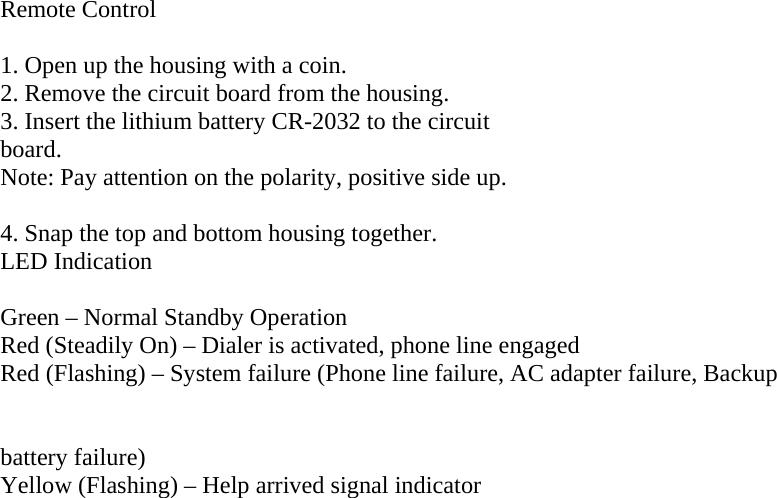
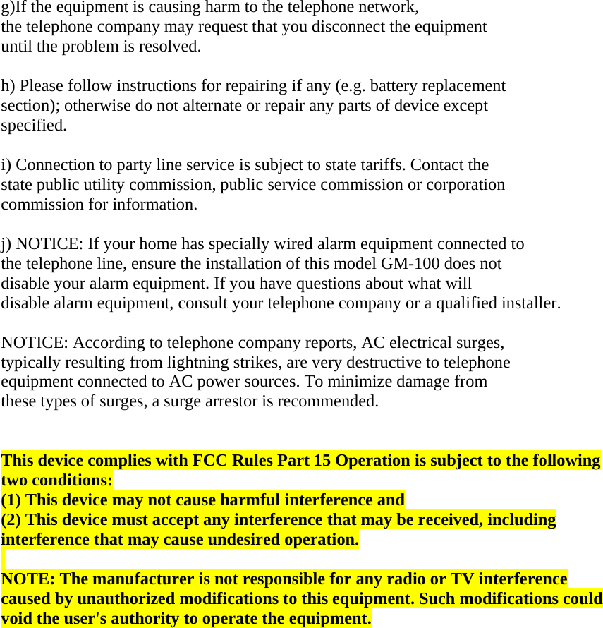
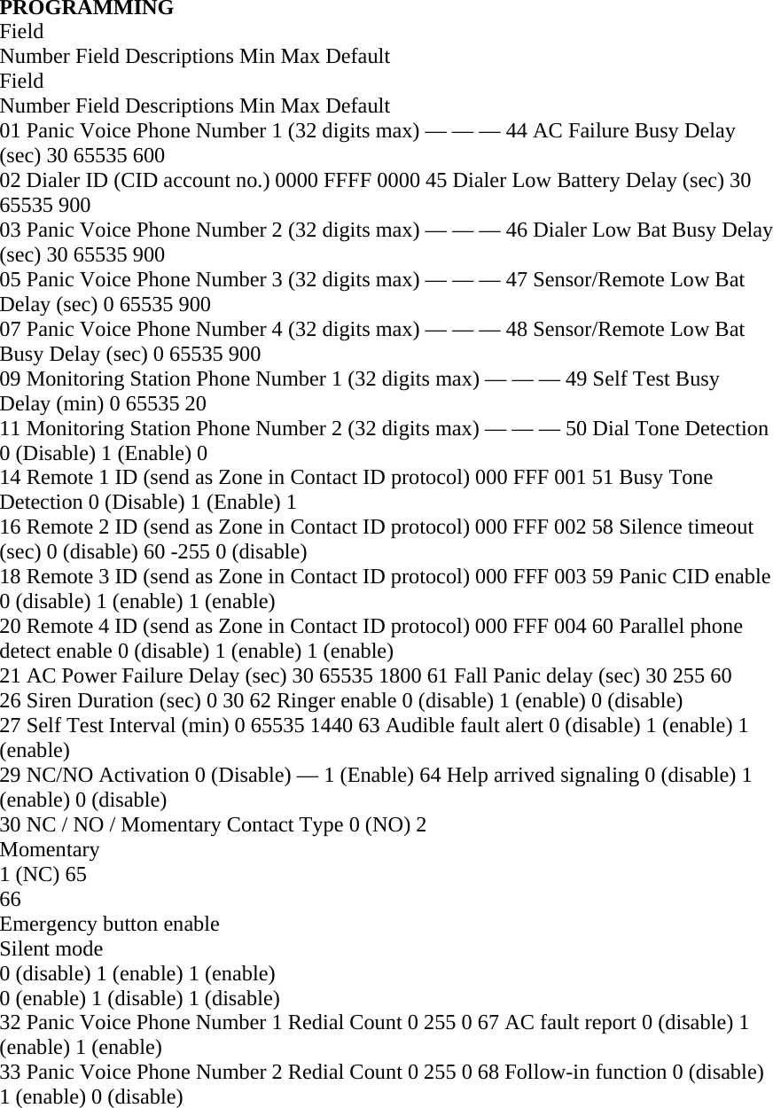
![• [*] + [2-digit Field Number] + [*] • Date Content + [#] 6) After enter the [#], you should hear 1 beep as a confirmation of a successive entry. If you hear 2 beeps, that means what you have entered is incorrect, you need to try again. 7) To terminate the call, press [0]+[*] on the touch tone phone. Once the phone line is disconnected, the dialer’s red LED will be off and only the green LED will be steadily on indicating standby condition. Remote Programming Emergency Numbers: If the system is in Stand By mode with “Auto Answer” function enabled, to enter the Remote Programming mode, follow the steps below. Step 1. Dial GM-100 and wait for auto-answering (Default is 20 rings) Step 2. Enter “123” (the default 4-digit Access Code) followed by “#”, via the phone set. The GM-100 will respond with two quick beeps to indicate it is ready now for Remote Programming Commands. The RED LED starts its blinking action to add visual indication. Step 3. Proceed to program your system by referring to the Command Table above. <<NNOOTTEE>> If the code is not correct, the caller has 15 seconds to enter the correct Access Code. If the correct code is not received after 15 seconds, GM-100 will hang up the line automatically. If Programming Command is not entered in 2 minutes, the GM-100 will exit Remote Progrmming Mode and release the line automatically. To exit Remote Programming mode, enter “99” followed by “#”.](https://usermanual.wiki/Nutek/UTII/User-Guide-1219948-Page-12.png)

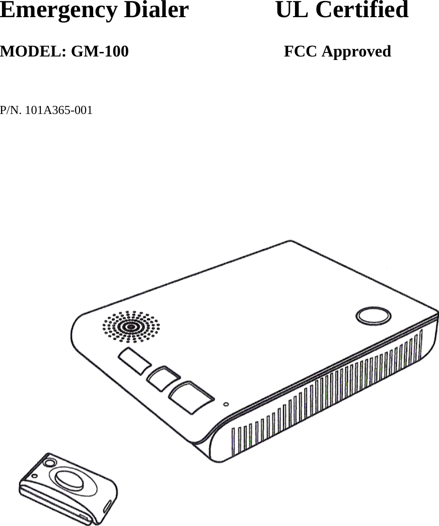
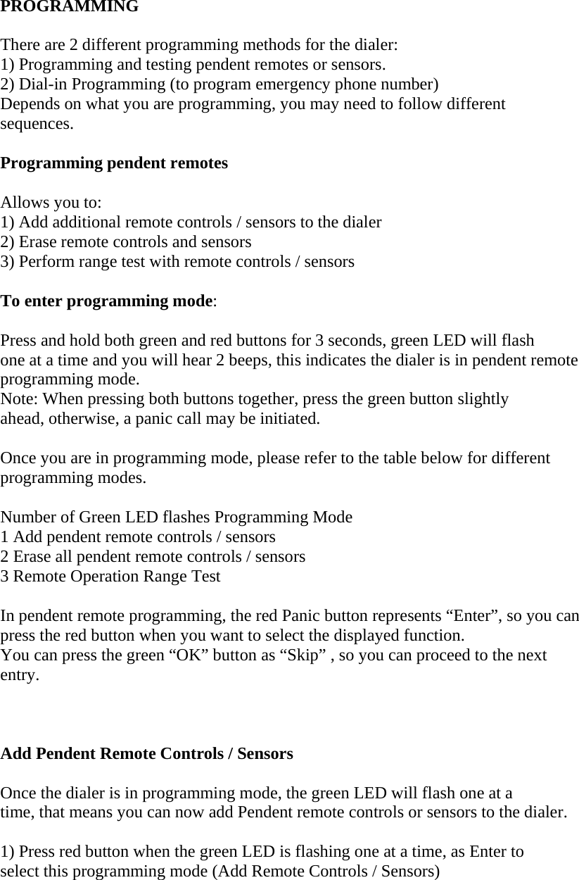
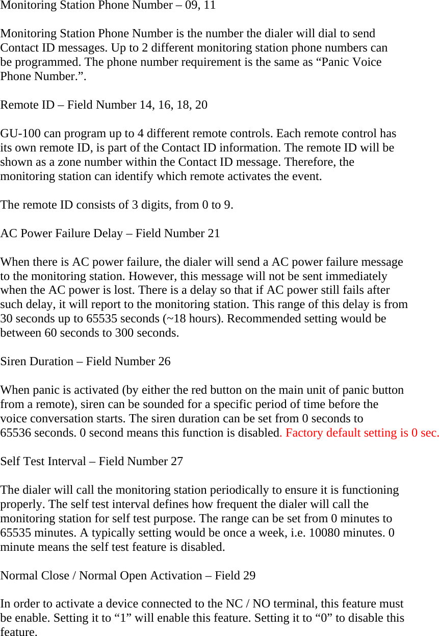
![PROGRAMMING Panic Voice Phone Number – Field Number 01, 03, 05, 07 This is the phone number the dialer will call when panic button is activated for 2-way voice speakerphone conversation. You may program up to 4 different numbers so if the first phone number cannot be called successfully, it will call the 2nd, 3rd, or 4th phone number. If the first Call Center phone number is called successfully, it will not call the rest of the Call Center phone numbers. • Each phone number can be up to 32 digits. • To program pause between digits, enter [*6] between 2 digits. • Multiple pause can be enters within a phone number To enter digits other than numeric numbers, follow the tables below. Symbols / Special Functions Enter Digits * *1 # *2 Pause Period (3 seconds) *6 Delete Phone number *9 Press *01* followed by *9 and #, the first monitoring station phone # can be erased. Follow the same sequence to erase 2nd, 3rd, or 4th phone number by entering [*02*], [*03*] or [*04*]. Dialer ID (Contact ID Account Number) – Field Number 02 Dialer ID is the Contact ID account number, so when the dialer reports any Contact ID events to the monitoring station, this is the unique number representing the dialer. Based on the Contact ID requirement, an account number has 4 digits, consists of 0 to 9 and letters B, C, D, E, or F. These are some examples of Contact ID account number: • 3847 • 2C3B To enter letters, B to F with a touch tone phone, follow the combinations below: Touch Tone Digits Contact ID Account Number Letter [*] + [1] B [*] + [2] C [*] + [3] D [*] + [4] E [*] + [5] F Example: To enter account number “8CE6”: -[*] + [02] + [*] + [8] + [*] + [2] + [*] + [4] + [6] + [#]](https://usermanual.wiki/Nutek/UTII/User-Guide-1219948-Page-15.png)
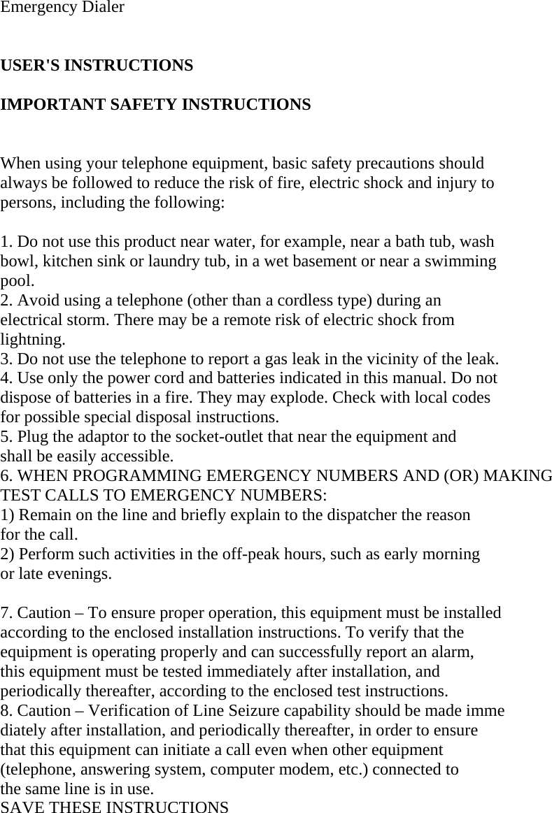
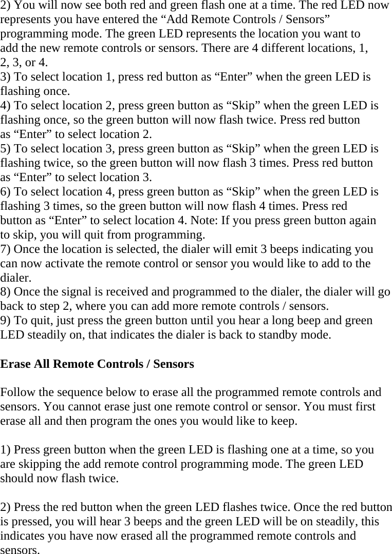
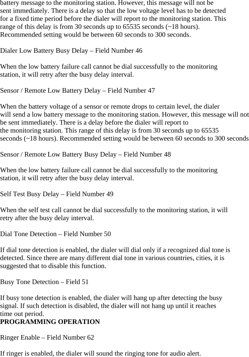
![PROGRAMMING NC / NO / Momentary – Field 30 There are 3 different relay outputs. Normal Open – Relay is open when there is no activation. Relay contact is closed (and latched) while panic is activated. Normal Close – Relay is close when there is no activation. Relay contact is opened (and remains open) while panic is activated. Momentary Contact – Relay contact will be closed momentary when panic signal is received. The relay output will be activated after the monitoring station picks up the call (operator pressing [4] to confirm picking up the call). The relay output will return to normal state when the call is finished (operator disconnects the phone line by pressing [0][*]) Panic Voice Phone Number Redial Count – Field Number 32, 33, 34,35 Each Panic Voice Phone Number can have its individual redial setting. If the 1st phone number is busy after the first trial, it will redial based on the redial count. If the call is not successful after all redial count for that phone number, it will dial the 2nd phone number. Monitoring Station Redial Count – Field Number 36, 37 If the Monitoring Station phone number is busy after the first trial, it will redial based on the redial count. Sensor Inactivity Alert Setting - Field Number 38, 39, 40, 41 A sensor can be programmed to the dialer as a remote, into one of the 4 remote locations. If a sensor for monitoring purpose, i.e. a motion sensor should be activated under normal condition at least once a day, you may set the inactivity alert time to 24 hours, that means if the sensor does not get triggered in 1 day, an inactivity alert Contact ID message will be sent to the monitoring station. AC Failure Busy Delay – Field Number 44 When the AC failure call cannot be dial successfully to the monitoring station, it will retry after the busy delay interval. Dialer Low Battery Delay – Field Number 45 When the back up battery voltage drops to certain level, the dialer will send a low](https://usermanual.wiki/Nutek/UTII/User-Guide-1219948-Page-17.png)
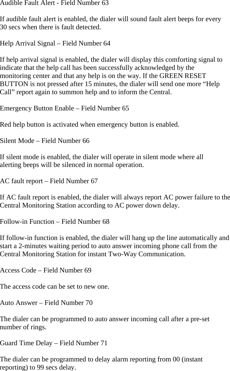
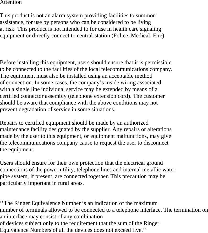
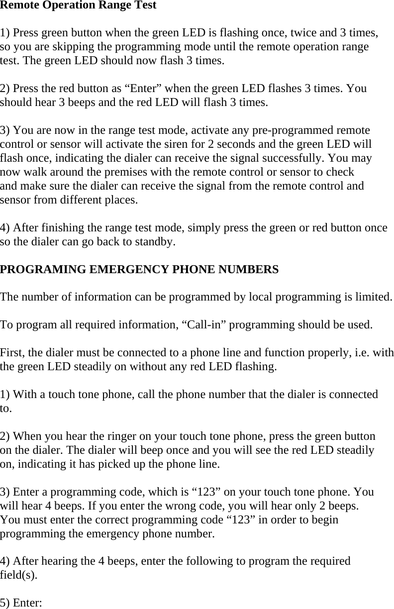
![Follow On Choice – Field Number 72 The dialer can be programmed to “Wait command”, “Two-Way Full Duplex Communication” or listen-in half duplex communication”. Remote All Device – Field Number 73 The dialer can be programmed to remove ALL previously learnt-in devices. Panic Call During emergency, user can press the panic button on the remote control to start the voice conversation. 1) Press the panic button on the remote control 2) The dialer will start to make the phone call, the red LED will be on and then flashes to indicate it is calling the pre-programmed emergency phone number. 3) Once the call is established, both sides can start the conversation. During the voice conversation, the orange LEDs on the dialer will continue to flash, to indicate the speakerphone mode is enabled. 4) To terminate the call, the user can simply press the green button on the dialer, or the recipient can press [9] to terminate the call. 5) Once the call is disconnected, the red LED will be off and the green LED will be steadily on. To pick up incoming call. 1. When the phone is ringing, press the Panic button on the remote, it will pick up the call. 2. To start conversation, speak into the dialer. 3. To hang up after the conversation, press the Panic button again.](https://usermanual.wiki/Nutek/UTII/User-Guide-1219948-Page-20.png)
![FCC Information Consumer Information: a) This equipment complies with Part 68 of the FCC rules and the requirements adopted by the ACTA. On the bottom of this equipment is a label that contains, among other information, a product identifier in the format US:AAAEQ##TXXXX. If requested, this number must be provided to the telephone company. b) An applicable certification jacks Universal Service Order Codes (USOC) for the equipment is provided (i.e., RJ11C) in the packaging with each piece of approved terminal equipment. c) A plug and jack used to connect this equipment to the premises wiring and telephone network must comply with the applicable FCC Part 68 rules and requirements adopted by the ACTA. A compliant telephone cord and modular plug is provided with this product. It is designed to be connected to a compatible modular jack that is also compliant. See installation instructions for details. d) The REN is used to determine the number of devices that may be connected to a telephone line. Excessive RENs on a telephone line may result in the devices not ringing in response to an incoming call. In most but not all areas, the sum of RENs should not exceed five (5.0). To be certain of the number of devices that may be connected to a line, as determined by the total RENs, contact the local telephone company. [For products approved after July 23, 2001, the REN for this product is part of the product identifier that has the format US:AAAEQ##TXXXX. The digits represented by ## are the REN without a decimal point (e.g., 03 is a REN of 0.3). For earlier products, the REN is separately shown on the label.] e) If this equipment GM-100 causes harm to the telephone network, the telephone company will notify you in advance that temporary discontinuance of service may be required. But if advance notice isn’t practical, the telephone company will notify the customer as soon as possible. Also, you will be advised of your right to file a complaint with the FCC if you believe it is necessary. f) The telephone company may make changes in its facilities, equipment, operations or procedures that could affect the operation of the equipment. If this happens the telephone company will provide advance notice in order for you to make necessary modifications to maintain uninterrupted service.](https://usermanual.wiki/Nutek/UTII/User-Guide-1219948-Page-22.png)