User Manual
Emergency Dialer UL Certified
MODEL: GM-100 FCC Approved
P/N. 101A365-001
Emergency Dialer
USER'S INSTRUCTIONS
IMPORTANT SAFETY INSTRUCTIONS
When using your telephone equipment, basic safety precautions should
always be followed to reduce the risk of fire, electric shock and injury to
persons, including the following:
1. Do not use this product near water, for example, near a bath tub, wash
bowl, kitchen sink or laundry tub, in a wet basement or near a swimming
pool.
2. Avoid using a telephone (other than a cordless type) during an
electrical storm. There may be a remote risk of electric shock from
lightning.
3. Do not use the telephone to report a gas leak in the vicinity of the leak.
4. Use only the power cord and batteries indicated in this manual. Do not
dispose of batteries in a fire. They may explode. Check with local codes
for possible special disposal instructions.
5. Plug the adaptor to the socket-outlet that near the equipment and
shall be easily accessible.
6. WHEN PROGRAMMING EMERGENCY NUMBERS AND (OR) MAKING
TEST CALLS TO EMERGENCY NUMBERS:
1) Remain on the line and briefly explain to the dispatcher the reason
for the call.
2) Perform such activities in the off-peak hours, such as early morning
or late evenings.
7. Caution – To ensure proper operation, this equipment must be installed
according to the enclosed installation instructions. To verify that the
equipment is operating properly and can successfully report an alarm,
this equipment must be tested immediately after installation, and
periodically thereafter, according to the enclosed test instructions.
8. Caution – Verification of Line Seizure capability should be made imme
diately after installation, and periodically thereafter, in order to ensure
that this equipment can initiate a call even when other equipment
(telephone, answering system, computer modem, etc.) connected to
the same line is in use.
SAVE THESE INSTRUCTIONS
Attention
This product is not an alarm system providing facilities to summon
assistance, for use by persons who can be considered to be living
at risk. This product is not intended to for use in health care signaling
equipment or directly connect to central-station (Police, Medical, Fire).
Before installing this equipment, users should ensure that it is permissible
to be connected to the facilities of the local telecommunications company.
The equipment must also be installed using an acceptable method
of connection. In some cases, the company’s inside wiring associated
with a single line individual service may be extended by means of a
certified connector assembly (telephone extension cord). The customer
should be aware that compliance with the above conditions may not
prevent degradation of service in some situations.
Repairs to certified equipment should be made by an authorized
maintenance facility designated by the supplier. Any repairs or alterations
made by the user to this equipment, or equipment malfunctions, may give
the telecommunications company cause to request the user to disconnect
the equipment.
Users should ensure for their own protection that the electrical ground
connections of the power utility, telephone lines and internal metallic water
pipe system, if present, are connected together. This precaution may be
particularly important in rural areas.
‘’The Ringer Equivalence Number is an indication of the maximum
number of terminals allowed to be connected to a telephone interface. The termination on
an interface may consist of any combination
of devices subject only to the requirement that the sum of the Ringer
Equivalence Numbers of all the devices does not exceed five.’’
CONTENT
Introduction.........................................................................................................................4
Overview....................................................................................................................... 4
Installation.......................................................................................................................... 6
Emergency Dialer........................................................................................................ 6
Remote Control........................................................................................................... 7
Programming................................................................................................................... .8
Local Programming.................................................................................................... 8
Add Remote Controls / Sensors............................................................................... 9
Erase All Remote Controls / Sensors........................................................................ 9
Record Voice Message............................................................................................ 10
Remote Operation Range Test............................................................................... 10
Programming Emergency Phone Number.......................................................... 11
Operation....................................................................................................................... . 19
Panic Call................................................................................................................... 19
Speed-Dial (Non-Panic Call)................................................................................... 19
System Failure................................................................................................................. 20
Monitoring Station DTMF Control................................................................................. 21
INTRODUCTION
Overview
Congratulations on your purchase of the Emergency Dialer Model GM-100. The
GM-100 is an advanced emergency dialer which is connected to a phone line
for assistance to monitoring station during emergency thru 2-way voice
conversation with Contact ID compatibility.
In the package, you should find the following:
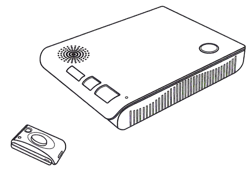
• One Emergency Dialer Model GM-100
• One Remote Control Model GM-TX 001
• One Telephone Cord
• One AC adapter
• One Rechargeable Battery for the Emergency Dialer
• One Lithium Battery for the Remote Control (CR-2032)
Emergency
Dialer
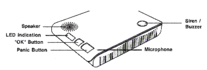
Front
Panic Button – Press this button to activate the emergency call
OK Button – Press this button to terminate or cancel the emergency call
LED Indication – Displays the status of the dialer
Speaker – Speaker for 2-way voice conversation
Microphone – Speak to this microphone during 2-way voice conversation
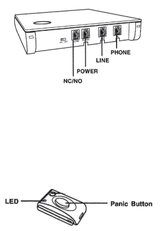
Back
On / Off – Turn the dialer On / Off
NC / NO – Activate the attached external devices during panic
Power – Connect AC adapter for power
Line – Connect telephone line
Phone – Connect a telephone to share the same phone line
Remote Control
• One User’s Instructions
Panic Button – Press this button to activate the emergency call
Please follow the instructions below to install the emergency dialer.
INSTALLATION
Emergency Dialer
Locating the Emergency Dialer
Consider the following when locating the dialer in your house. The dialer should
be located:
-near a phone line
-near an AC outlet
-on a desk or countertop where user can reach easily
Note: A conventional telephone can be placed on top of the emergency dialer,
however, the telephone should not cover the microphone or speaker on the
dialer.
Once you have located where the dialer should be installed, you can connect the
dialer to the phone line and AC power.
1. Plug in the phone line – One end of the
telephone cord should be plugged into the
phone outlet on the wall, the other end of
the cord should be connected to the “Line”
socket on the dialer.
2. Plug in the power – Plug the AC adapter
to a nearby AC outlet, the other end should
be connected to the “Power” socket on the
dialer.
3. Connect the rechargeable battery –
Remove the battery cover on the bottom of
the dialer. Insert the rechargeable battery
and plug in the battery connector to the
terminal as shown.
4. Power up the dialer – You may now
power up the dialer by sliding the power
switch to “ON” position. You will hear 3
beeps indicating the dialer is on and all
LED’s will flash once.
5. Standby – The dialer is in standby mode
if the green LED is on. If the green LED is
not on, or if the red LED is flashing and
buzzer beeping, this indicates the dialer is
not connected properly. Please refer to the
“System Failure” section to diagnostic the
problem. 1 2 3
Remote Control
1. Open up the housing with a coin.
2. Remove the circuit board from the housing.
3. Insert the lithium battery CR-2032 to the circuit
board.
Note: Pay attention on the polarity, positive side up.
4. Snap the top and bottom housing together.
LED Indication
Green – Normal Standby Operation
Red (Steadily On) – Dialer is activated, phone line engaged
Red (Flashing) – System failure (Phone line failure, AC adapter failure, Backup
battery failure)
Yellow (Flashing) – Help arrived signal indicator
PROGRAMMING
There are 2 different programming methods for the dialer:
1) Programming and testing pendent remotes or sensors.
2) Dial-in Programming (to program emergency phone number)
Depends on what you are programming, you may need to follow different
sequences.
Programming pendent remotes
Allows you to:
1) Add additional remote controls / sensors to the dialer
2) Erase remote controls and sensors
3) Perform range test with remote controls / sensors
To enter programming mode:
Press and hold both green and red buttons for 3 seconds, green LED will flash
one at a time and you will hear 2 beeps, this indicates the dialer is in pendent remote
programming mode.
Note: When pressing both buttons together, press the green button slightly
ahead, otherwise, a panic call may be initiated.
Once you are in programming mode, please refer to the table below for different
programming modes.
Number of Green LED flashes Programming Mode
1 Add pendent remote controls / sensors
2 Erase all pendent remote controls / sensors
3 Remote Operation Range Test
In pendent remote programming, the red Panic button represents “Enter”, so you can
press the red button when you want to select the displayed function.
You can press the green “OK” button as “Skip” , so you can proceed to the next
entry.
Add Pendent Remote Controls / Sensors
Once the dialer is in programming mode, the green LED will flash one at a
time, that means you can now add Pendent remote controls or sensors to the dialer.
1) Press red button when the green LED is flashing one at a time, as Enter to
select this programming mode (Add Remote Controls / Sensors)
2) You will now see both red and green flash one at a time. The red LED now
represents you have entered the “Add Remote Controls / Sensors”
programming mode. The green LED represents the location you want to
add the new remote controls or sensors. There are 4 different locations, 1,
2, 3, or 4.
3) To select location 1, press red button as “Enter” when the green LED is
flashing once.
4) To select location 2, press green button as “Skip” when the green LED is
flashing once, so the green button will now flash twice. Press red button
as “Enter” to select location 2.
5) To select location 3, press green button as “Skip” when the green LED is
flashing twice, so the green button will now flash 3 times. Press red button
as “Enter” to select location 3.
6) To select location 4, press green button as “Skip” when the green LED is
flashing 3 times, so the green button will now flash 4 times. Press red
button as “Enter” to select location 4. Note: If you press green button again
to skip, you will quit from programming.
7) Once the location is selected, the dialer will emit 3 beeps indicating you
can now activate the remote control or sensor you would like to add to the
dialer.
8) Once the signal is received and programmed to the dialer, the dialer will go
back to step 2, where you can add more remote controls / sensors.
9) To quit, just press the green button until you hear a long beep and green
LED steadily on, that indicates the dialer is back to standby mode.
Erase All Remote Controls / Sensors
Follow the sequence below to erase all the programmed remote controls and
sensors. You cannot erase just one remote control or sensor. You must first
erase all and then program the ones you would like to keep.
1) Press green button when the green LED is flashing one at a time, so you
are skipping the add remote control programming mode. The green LED
should now flash twice.
2) Press the red button when the green LED flashes twice. Once the red button
is pressed, you will hear 3 beeps and the green LED will be on steadily, this
indicates you have now erased all the programmed remote controls and
sensors.
Remote Operation Range Test
1) Press green button when the green LED is flashing once, twice and 3 times,
so you are skipping the programming mode until the remote operation range
test. The green LED should now flash 3 times.
2) Press the red button as “Enter” when the green LED flashes 3 times. You
should hear 3 beeps and the red LED will flash 3 times.
3) You are now in the range test mode, activate any pre-programmed remote
control or sensor will activate the siren for 2 seconds and the green LED will
flash once, indicating the dialer can receive the signal successfully. You may
now walk around the premises with the remote control or sensor to check
and make sure the dialer can receive the signal from the remote control and
sensor from different places.
4) After finishing the range test mode, simply press the green or red button once
so the dialer can go back to standby.
PROGRAMING EMERGENCY PHONE NUMBERS
The number of information can be programmed by local programming is limited.
To program all required information, “Call-in” programming should be used.
First, the dialer must be connected to a phone line and function properly, i.e. with
the green LED steadily on without any red LED flashing.
1) With a touch tone phone, call the phone number that the dialer is connected
to.
2) When you hear the ringer on your touch tone phone, press the green button
on the dialer. The dialer will beep once and you will see the red LED steadily
on, indicating it has picked up the phone line.
3) Enter a programming code, which is “123” on your touch tone phone. You
will hear 4 beeps. If you enter the wrong code, you will hear only 2 beeps.
You must enter the correct programming code “123” in order to begin
programming the emergency phone number.
4) After hearing the 4 beeps, enter the following to program the required
field(s).
5) Enter:

• [*] + [2-digit Field Number] + [*]
• Date Content + [#]
6) After enter the [#], you should hear 1 beep as a confirmation of a successive
entry. If you hear 2 beeps, that means what you have entered is incorrect,
you need to try again.
7) To terminate the call, press [0]+[*] on the touch tone phone. Once the phone
line is disconnected, the dialer’s red LED will be off and only the green LED
will be steadily on indicating standby condition.
Remote Programming Emergency Numbers:
If the system is in Stand By mode with “Auto Answer” function enabled, to enter the
Remote Programming mode, follow the steps below.
Step 1. Dial GM-100 and wait for auto-answering (Default is 20 rings)
Step 2. Enter “123” (the default 4-digit Access Code) followed by “#”, via the phone set.
The GM-100 will respond with two quick beeps to indicate it is ready now for
Remote Programming Commands. The RED LED starts its blinking action to
add visual indication.
Step 3. Proceed to program your system by referring to the Command Table above.
<
<N
NO
OT
TE
E>
>
If the code is not correct, the caller has 15 seconds to enter the correct
Access Code.
If the correct code is not received after 15 seconds, GM-100 will hang
up the line automatically.
If Programming Command is not entered in 2 minutes, the GM-100 will
exit Remote Progrmming Mode and release the line automatically.
To exit Remote Programming mode, enter “99” followed by “#”.
PROGRAMMING
Field
Number Field Descriptions Min Max Default
Field
Number Field Descriptions Min Max Default
01 Panic Voice Phone Number 1 (32 digits max) — — — 44 AC Failure Busy Delay
(sec) 30 65535 600
02 Dialer ID (CID account no.) 0000 FFFF 0000 45 Dialer Low Battery Delay (sec) 30
65535 900
03 Panic Voice Phone Number 2 (32 digits max) — — — 46 Dialer Low Bat Busy Delay
(sec) 30 65535 900
05 Panic Voice Phone Number 3 (32 digits max) — — — 47 Sensor/Remote Low Bat
Delay (sec) 0 65535 900
07 Panic Voice Phone Number 4 (32 digits max) — — — 48 Sensor/Remote Low Bat
Busy Delay (sec) 0 65535 900
09 Monitoring Station Phone Number 1 (32 digits max) — — — 49 Self Test Busy
Delay (min) 0 65535 20
11 Monitoring Station Phone Number 2 (32 digits max) — — — 50 Dial Tone Detection
0 (Disable) 1 (Enable) 0
14 Remote 1 ID (send as Zone in Contact ID protocol) 000 FFF 001 51 Busy Tone
Detection 0 (Disable) 1 (Enable) 1
16 Remote 2 ID (send as Zone in Contact ID protocol) 000 FFF 002 58 Silence timeout
(sec) 0 (disable) 60 -255 0 (disable)
18 Remote 3 ID (send as Zone in Contact ID protocol) 000 FFF 003 59 Panic CID enable
0 (disable) 1 (enable) 1 (enable)
20 Remote 4 ID (send as Zone in Contact ID protocol) 000 FFF 004 60 Parallel phone
detect enable 0 (disable) 1 (enable) 1 (enable)
21 AC Power Failure Delay (sec) 30 65535 1800 61 Fall Panic delay (sec) 30 255 60
26 Siren Duration (sec) 0 30 62 Ringer enable 0 (disable) 1 (enable) 0 (disable)
27 Self Test Interval (min) 0 65535 1440 63 Audible fault alert 0 (disable) 1 (enable) 1
(enable)
29 NC/NO Activation 0 (Disable) — 1 (Enable) 64 Help arrived signaling 0 (disable) 1
(enable) 0 (disable)
30 NC / NO / Momentary Contact Type 0 (NO) 2
Momentary
1 (NC) 65
66
Emergency button enable
Silent mode
0 (disable) 1 (enable) 1 (enable)
0 (enable) 1 (disable) 1 (disable)
32 Panic Voice Phone Number 1 Redial Count 0 255 0 67 AC fault report 0 (disable) 1
(enable) 1 (enable)
33 Panic Voice Phone Number 2 Redial Count 0 255 0 68 Follow-in function 0 (disable)
1 (enable) 0 (disable)
34 Panic Voice Phone Number 3 Redial Count 0 255 0 69 Access code 0000 9999 1
35 Panic Voice Phone Number 4 Redial Count 0 255 0 70 Auto answer 0 (disable) 32 20
36 Monitoring Station 1 Redial Count 0 255 0 71 Guard time delay 00 (instant) 99 10
37 Monitoring Station 2 Redial Count 0 255 0 72 Follow on choice 0 (wait) 2 (two way)1
(listen)
38 Sensor 1 24 Inactive Alert (min) 0 65535 0 73 Remote all device ———
39 Sensor 2 24 Inactive Alert (min) 0 65535 0 74 Remote pendant 1 ———
40 Sensor 3 24 Inactive Alert (min) 0 65535 0 75 Remote pendant 2 ———
41 Sensor 4 24 Inactive Alert (min) 0 65535 0 76 Remote pendant 3 ———
42 Speed Dial Phone Number (32 digits max) — — — 77 Remote pendant 4 ———
PROGRAMMING
Panic Voice Phone Number – Field Number 01, 03, 05, 07
This is the phone number the dialer will call when panic button is activated for
2-way voice speakerphone conversation. You may program up to 4 different
numbers so if the first phone number cannot be called successfully, it will call
the 2nd, 3rd, or 4th phone number. If the first Call Center phone number is called
successfully, it will not call the rest of the Call Center phone numbers.
• Each phone number can be up to 32 digits.
• To program pause between digits, enter [*6] between 2 digits.
• Multiple pause can be enters within a phone number
To enter digits other than numeric numbers, follow the tables below.
Symbols / Special Functions Enter Digits
* *1
# *2
Pause Period (3 seconds) *6
Delete Phone number *9
Press *01* followed by *9 and #, the first monitoring station phone # can be erased.
Follow the same sequence to erase 2nd, 3rd, or 4th phone number by entering [*02*],
[*03*] or [*04*].
Dialer ID (Contact ID Account Number) – Field Number 02
Dialer ID is the Contact ID account number, so when the dialer reports any
Contact ID events to the monitoring station, this is the unique number representing the
dialer. Based on the Contact ID requirement, an account number
has 4 digits, consists of 0 to 9 and letters B, C, D, E, or F. These are some
examples of Contact ID account number:
• 3847
• 2C3B
To enter letters, B to F with a touch tone phone, follow the combinations below:
Touch Tone Digits Contact ID Account Number Letter
[*] + [1] B
[*] + [2] C
[*] + [3] D
[*] + [4] E
[*] + [5] F
Example: To enter account number “8CE6”:
-[*] + [02] + [*] + [8] + [*] + [2] + [*] + [4] + [6] + [#]
Monitoring Station Phone Number – 09, 11
Monitoring Station Phone Number is the number the dialer will dial to send
Contact ID messages. Up to 2 different monitoring station phone numbers can
be programmed. The phone number requirement is the same as “Panic Voice
Phone Number.”.
Remote ID – Field Number 14, 16, 18, 20
GU-100 can program up to 4 different remote controls. Each remote control has
its own remote ID, is part of the Contact ID information. The remote ID will be
shown as a zone number within the Contact ID message. Therefore, the
monitoring station can identify which remote activates the event.
The remote ID consists of 3 digits, from 0 to 9.
AC Power Failure Delay – Field Number 21
When there is AC power failure, the dialer will send a AC power failure message
to the monitoring station. However, this message will not be sent immediately
when the AC power is lost. There is a delay so that if AC power still fails after
such delay, it will report to the monitoring station. This range of this delay is from
30 seconds up to 65535 seconds (~18 hours). Recommended setting would be
between 60 seconds to 300 seconds.
Siren Duration – Field Number 26
When panic is activated (by either the red button on the main unit of panic button
from a remote), siren can be sounded for a specific period of time before the
voice conversation starts. The siren duration can be set from 0 seconds to
65536 seconds. 0 second means this function is disabled. Factory default setting is 0 sec.
Self Test Interval – Field Number 27
The dialer will call the monitoring station periodically to ensure it is functioning
properly. The self test interval defines how frequent the dialer will call the
monitoring station for self test purpose. The range can be set from 0 minutes to
65535 minutes. A typically setting would be once a week, i.e. 10080 minutes. 0
minute means the self test feature is disabled.
Normal Close / Normal Open Activation – Field 29
In order to activate a device connected to the NC / NO terminal, this feature must
be enable. Setting it to “1” will enable this feature. Setting it to “0” to disable this
feature.
PROGRAMMING
NC / NO / Momentary – Field 30
There are 3 different relay outputs.
Normal Open – Relay is open when there is no activation. Relay contact is closed
(and latched) while panic is activated.
Normal Close – Relay is close when there is no activation. Relay contact is
opened (and remains open) while panic is activated.
Momentary Contact – Relay contact will be closed momentary when panic signal
is received.
The relay output will be activated after the monitoring station picks up the call
(operator pressing [4] to confirm picking up the call). The relay output will return to
normal state when the call is finished (operator disconnects the phone line by
pressing [0][*])
Panic Voice Phone Number Redial Count – Field Number 32, 33, 34,35
Each Panic Voice Phone Number can have its individual redial setting. If the 1st
phone number is busy after the first trial, it will redial based on the redial count. If
the call is not successful after all redial count for that phone number, it will dial the
2nd phone number.
Monitoring Station Redial Count – Field Number 36, 37
If the Monitoring Station phone number is busy after the first trial, it will redial
based on the redial count.
Sensor Inactivity Alert Setting - Field Number 38, 39, 40, 41
A sensor can be programmed to the dialer as a remote, into one of the 4 remote
locations. If a sensor for monitoring purpose, i.e. a motion sensor should be
activated under normal condition at least once a day, you may set the inactivity
alert time to 24 hours, that means if the sensor does not get triggered in 1 day, an
inactivity alert Contact ID message will be sent to the monitoring station.
AC Failure Busy Delay – Field Number 44
When the AC failure call cannot be dial successfully to the monitoring station, it
will retry after the busy delay interval.
Dialer Low Battery Delay – Field Number 45
When the back up battery voltage drops to certain level, the dialer will send a low
battery message to the monitoring station. However, this message will not be
sent immediately. There is a delay so that the low voltage level has to be detected
for a fixed time period before the dialer will report to the monitoring station. This
range of this delay is from 30 seconds up to 65535 seconds (~18 hours).
Recommended setting would be between 60 seconds to 300 seconds.
Dialer Low Battery Busy Delay – Field Number 46
When the low battery failure call cannot be dial successfully to the monitoring
station, it will retry after the busy delay interval.
Sensor / Remote Low Battery Delay – Field Number 47
When the battery voltage of a sensor or remote drops to certain level, the dialer
will send a low battery message to the monitoring station. However, this message will not
be sent immediately. There is a delay before the dialer will report to
the monitoring station. This range of this delay is from 30 seconds up to 65535
seconds (~18 hours). Recommended setting would be between 60 seconds to 300 seconds
Sensor / Remote Low Battery Busy Delay – Field Number 48
When the low battery failure call cannot be dial successfully to the monitoring
station, it will retry after the busy delay interval.
Self Test Busy Delay – Field Number 49
When the self test call cannot be dial successfully to the monitoring station, it will
retry after the busy delay interval.
Dial Tone Detection – Field Number 50
If dial tone detection is enabled, the dialer will dial only if a recognized dial tone is
detected. Since there are many different dial tone in various countries, cities, it is
suggested that to disable this function.
Busy Tone Detection – Field 51
If busy tone detection is enabled, the dialer will hang up after detecting the busy
signal. If such detection is disabled, the dialer will not hang up until it reaches
time out period.
PROGRAMMING OPERATION
Ringer Enable – Field Number 62
If ringer is enabled, the dialer will sound the ringing tone for audio alert.
Audible Fault Alert - Field Number 63
If audible fault alert is enabled, the dialer will sound fault alert beeps for every
30 secs when there is fault detected.
Help Arrival Signal – Field Number 64
If help arrival signal is enabled, the dialer will display this comforting signal to
indicate that the help call has been successfully acknowledged by the
monitoring center and that any help is on the way. If the GREEN RESET
BUTTON is not pressed after 15 minutes, the dialer will send one more “Help
Call” report again to summon help and to inform the Central.
Emergency Button Enable – Field Number 65
Red help button is activated when emergency button is enabled.
Silent Mode – Field Number 66
If silent mode is enabled, the dialer will operate in silent mode where all
alerting beeps will be silenced in normal operation.
AC fault report – Field Number 67
If AC fault report is enabled, the dialer will always report AC power failure to the
Central Monitoring Station according to AC power down delay.
Follow-in Function – Field Number 68
If follow-in function is enabled, the dialer will hang up the line automatically and
start a 2-minutes waiting period to auto answer incoming phone call from the
Central Monitoring Station for instant Two-Way Communication.
Access Code – Field Number 69
The access code can be set to new one.
Auto Answer – Field Number 70
The dialer can be programmed to auto answer incoming call after a pre-set
number of rings.
Guard Time Delay – Field Number 71
The dialer can be programmed to delay alarm reporting from 00 (instant
reporting) to 99 secs delay.
Follow On Choice – Field Number 72
The dialer can be programmed to “Wait command”, “Two-Way Full Duplex
Communication” or listen-in half duplex communication”.
Remote All Device – Field Number 73
The dialer can be programmed to remove ALL previously learnt-in devices.
Panic Call
During emergency, user can press the panic button on the remote control to start
the voice conversation.
1) Press the panic button on the remote control
2) The dialer will start to make the phone call, the red LED will be on and then
flashes to indicate it is calling the pre-programmed emergency phone
number.
3) Once the call is established, both sides can start the conversation. During
the voice conversation, the orange LEDs on the dialer will continue to flash,
to indicate the speakerphone mode is enabled.
4) To terminate the call, the user can simply press the green button on the
dialer, or the recipient can press [9] to terminate the call.
5) Once the call is disconnected, the red LED will be off and the green LED will
be steadily on.
To pick up incoming call.
1. When the phone is ringing, press the Panic button on the remote, it
will pick up the call.
2. To start conversation, speak into the dialer.
3. To hang up after the conversation, press the Panic button again.
SYSTEM FAILURE MONITORING STATION DTMF CONTROL
The system will monitor itself for failures, such as: Monitoring Station can control the
dialer during a panic voice conversation.
Follow the commands below for various functions.
1) AC power failure (No AC power from the adapter)
2) Phone line failure (No phone line is connected)
3) Backup battery failure (Backup battery is low)
During a AC power failure, the dialer itself will beep every 30 seconds and the
red LED will flash. There is no beeping for phone line or backup battery failure. But
the red LED will flash. When there is failure condition, you should check the 3
mentioned failures, whether there is any loose connection between the dialer
and the AC adapter, backup battery or phone line. Once the failure is fixed, the
beeping will stop and the green LED will be on steadily.
You can also disable the beeping of AC power failure. Press the green button
while it is beeping, the buzzer will stop beeping. It will beep again if another
failure occurs. Contact ID Event Codes
You can also completely disable beeping by turning off the beep with Audible
fault alert Field Number, 63.
DTMF Digits Functions
1 One-Way Speak (Dialer)
2 Two-Way conversation
3 One-Way Listen (Dialer)
9 Disconnect
Contact ID Event Event Qualifier + Event Code
Panic – Panel Panic button 1 + 101 (zone 000)
Panic – Remote Control 1 + 101 (zone 00x) “x” is the remote
number from 1 to 4
AC loss (main unit) 1 + 301
AC back to normal after loss 3 + 301
Low battery (main unit) 1 + 302
Remote low battery 1 + 384 (zone 00x) “x” is the remote
Self Test
number from 1 to 4
1 + 602
Inactivity Report 1 + 654
FCC Information
Consumer Information:
a) This equipment complies with Part 68 of the FCC rules and the requirements adopted
by the ACTA. On the bottom of this equipment is a label
that contains, among other information, a product identifier in the format
US:AAAEQ##TXXXX. If requested, this number must be provided to the
telephone company.
b) An applicable certification jacks Universal Service Order Codes (USOC)
for the equipment is provided (i.e., RJ11C) in the packaging with each
piece of approved terminal equipment.
c) A plug and jack used to connect this equipment to the premises wiring
and telephone network must comply with the applicable FCC Part 68
rules and requirements adopted by the ACTA. A compliant telephone
cord and modular plug is provided with this product. It is designed to be
connected to a compatible modular jack that is also compliant. See
installation instructions for details.
d) The REN is used to determine the number of devices that may be connected to a
telephone line. Excessive RENs on a telephone line may
result in the devices not ringing in response to an incoming call. In most
but not all areas, the sum of RENs should not exceed five (5.0). To be
certain of the number of devices that may be connected to a line, as
determined by the total RENs, contact the local telephone company. [For
products approved after July 23, 2001, the REN for this product is part of
the product identifier that has the format US:AAAEQ##TXXXX. The digits
represented by ## are the REN without a decimal point (e.g., 03 is a
REN of 0.3). For earlier products, the REN is separately shown on the label.]
e) If this equipment GM-100 causes harm to the telephone network, the
telephone company will notify you in advance that temporary discontinuance of service
may be required. But if advance notice isn’t practical, the
telephone company will notify the customer as soon as possible. Also,
you will be advised of your right to file a complaint with the FCC if you
believe it is necessary.
f) The telephone company may make changes in its facilities, equipment,
operations or procedures that could affect the operation of the equipment.
If this happens the telephone company will provide advance notice in
order for you to make necessary modifications to maintain uninterrupted
service.

g)If the equipment is causing harm to the telephone network,
the telephone company may request that you disconnect the equipment
until the problem is resolved.
h) Please follow instructions for repairing if any (e.g. battery replacement
section); otherwise do not alternate or repair any parts of device except
specified.
i) Connection to party line service is subject to state tariffs. Contact the
state public utility commission, public service commission or corporation
commission for information.
j) NOTICE: If your home has specially wired alarm equipment connected to
the telephone line, ensure the installation of this model GM-100 does not
disable your alarm equipment. If you have questions about what will
disable alarm equipment, consult your telephone company or a qualified installer.
NOTICE: According to telephone company reports, AC electrical surges,
typically resulting from lightning strikes, are very destructive to telephone
equipment connected to AC power sources. To minimize damage from
these types of surges, a surge arrestor is recommended.
This device complies with FCC Rules Part 15 Operation is subject to the following
two conditions:
(1) This device may not cause harmful interference and
(2) This device must accept any interference that may be received, including
interference that may cause undesired operation.
NOTE: The manufacturer is not responsible for any radio or TV interference
caused by unauthorized modifications to this equipment. Such modifications could
void the user's authority to operate the equipment.