OEM Controls ST-5XX ST-5 User Manual ST 900 Manual Rev C
OEM Controls, Inc. ST-5 ST 900 Manual Rev C
User Manual

ST-
900 Installation Guide and User’s Manual
C
ELLULAR
U
Installation Guide and
A Division of OEM Controls, Inc.
900 Installation Guide and User’s Manual
ST-900
ELLULAR
S
ERVICE
T
RACKER
U
SER
M
ANUAL
Installation Guide and
User’s Manual
OEM Data Delivery,
A Division of OEM Controls, Inc.
10 Controls Drive
Shelton, CT 06484
203-929-8431
www.service-tracker.com
DOC # 20977
Page 1
RACKER

DOC # 20977
ST-900 Installation Guide and User’s Manual Page 2
COPYRIGHT: COPYRIGHT © 2009 BY OEM DATA DELIVERY, A DIVISION OF
OEM CONTROLS, INC., ALL RIGHTS RESERVED.
DISCLAIMER AND LIMITATION OF LIABILITY: OEM DATA DELIVERY
UNDERTAKES NO RESPONSIBILITY FOR ANY LOSS OR CLAIMS BY THIRD
PARTIES WHICH MAY ARISE THROUGH THE USE OF THIS HARDWARE.
OEM DATA DELIVERY UNDERTAKES NO RESPONSIBILITY FOR ANY
DAMAGE OR LOSS CAUSED BY DELETION OF DATA AS A RESULT OF
MALFUNCTION, DEAD BATTERY, OR REPAIRS. BE SURE TO MAKE
BACKUP COPIES OF ALL IMPORTANT DATA ON OTHER MEDIA TO
PROTECT AGAINST DATA LOSS.
WARNING: IT IS THE PURCHASER’S RESPONSIBILITY TO DETERMINE THE
SUITABILITY OF OEM DATA DELIVERY PRODUCT FOR AN INTENDED
APPLICATION AND TO ENSURE THAT IT IS INSTALLED AND GUARDED IN
ACCORDANCE WITH ALL FEDERAL, STATE, LOCAL AND PRIVATE SAFETY
AND HEALTH REGULATIONS, CODES AND STANDARDS.
WARNING: NO MODIFICATIONS TO THE UNIT ARE TO BE MADE. ANY
CHANGES OR MODIFICATIONS NOT EXPRESSLY APPROVED BY THE OEM
CONTROLS, INC. COULD VOID THE PURCHASER’S AUTHORITY TO OPERATE
THE EQUIPMENT.
THIS DEVICE COMPLIES WITH PART 15 OF THE FCC RULES. OPERATION IS
SUBJECT TO THE FOLLOWING TWO CONDITIONS: (1) THIS DEVICE MAY NOT
CAUSE HARMFUL INTERFERENCE, AND (2) THIS DEVICE MUST ACCEPT ANY
INTERFERENCE RECEIVED, INCLUDING INTERFERENCE THAT MAY CAUSE
UNDESIRED OPERATION.
DOCUMENT NUMBER: 20977
DATE OF REVISION: 6/14/10 – Rev. C
ABOUT THIS GUIDE:
THIS GUIDE PROVIDES BASIC INSTRUCTION ON THE USE OF THE ST-900
CELLULAR SERVICE TRACKER.

DOC # 20977
ST-900 Installation Guide and User’s Manual Page 3
Introduction 4
General Information 4
Radio Communication 4
GPS Communication 4
GPRS Communication 4
Models Available 5
Schematic Model 100 6
Schematic Model 102 7
Schematic Model 103 8
Electrical Installation 9
Installing an ST-900 Cellular Service Tracker 13
Installing the GPS 15
Equipment Needed 15
ST-900 Features 16
Programming the ST-900 17
Setting an Equipment Profile 18
Loading your Profile 19
Diagnosing the ST-900 20
Technical Specifications 22
7 Segment Display 23
Contents

DOC # 20977
ST-900 Installation Guide and User’s Manual Page 4
General Information
OEM Data Delivery, a leading developer of rugged electronic tools for managing worksites and
high-end equipment, has introduced a versatile system for tracking equipment at remote
locations.
The ST-900 generates the real-time information needed to maximize revenue and cut waste.
The ST-900 is one of the most powerful, and versatile tools available for precise job costing. It
was engineered for severe service performance at construction, landfill, rental and other
complex operations. Implementation is quick and training typically requires just a few hours.
The ST-900 works with the GoPod from OEM Data Delivery. This concealed computer
installs in lube/fuel trucks, low boy trucks, and supervisor’s vehicles for additional process data
capture, including fuel, driver logs, and mechanic work logs. It has a GPS antenna and a radio
antenna. GPS coordinates are stamped into the record as hour data is collected. Information is
collected passively, within range of a 300 foot line of sight, and transmitted via secure radio link.
The ST-900 works remotely using cellular GPRS. This allows the user to capture data from the
tracker, the profile, work/idle/run logs, latitude, longitude, travel logs, and count/duration logs. It
also allows the user to disable or enable the ignition on the vehicle, profile the tracker, and
modify the real time clock to adjust for daylight savings time and time zone differences.
Radio Communication
The radio will allow you to retrieve all ST-900 data, such as the profile, service alerts,
work/idle/run/count duration logs, and GPS information (latitude and longitude). You can
retrieve this data using a GoPod. The Aceeca/Gopod will allow the user to update (modify) the
real time clock. The Aceeca will not be used to capture the work/idle/run, count/duration logs.
GPS Communication
The GPS will give the user the positional information of the ST-900 (Latitude and Longitude).
The speed over ground is used to derive the cumulative machine mileage.
GPRS Communication
The GPRS will allow the user to have remote connectivity using cellular technology. The user
can obtain information on a PC with OEM Server Software that will communicate with the ST-
900 using the GPRS network. The Cellular GPRS will allow you to retrieve all data, such as the
count/duration logs. It also allows the user to disable/enable the ignition on the vehicle, profile
the tracker and modify the real time clock to adjust for daylight saving time and time zone
differences.

DOC # 20977
ST-900 Installation Guide and User’s Manual Page 5
Product Cable Features
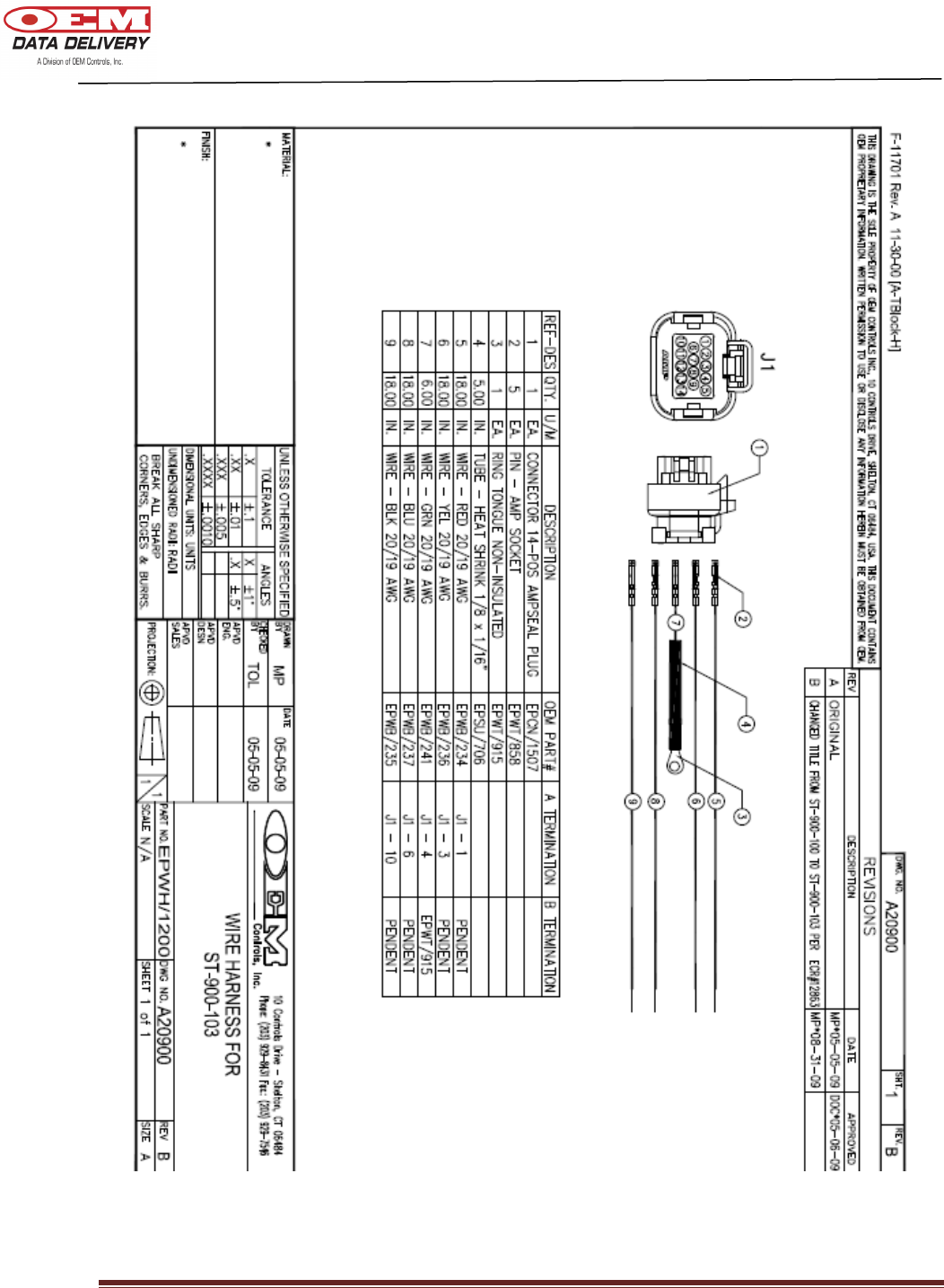
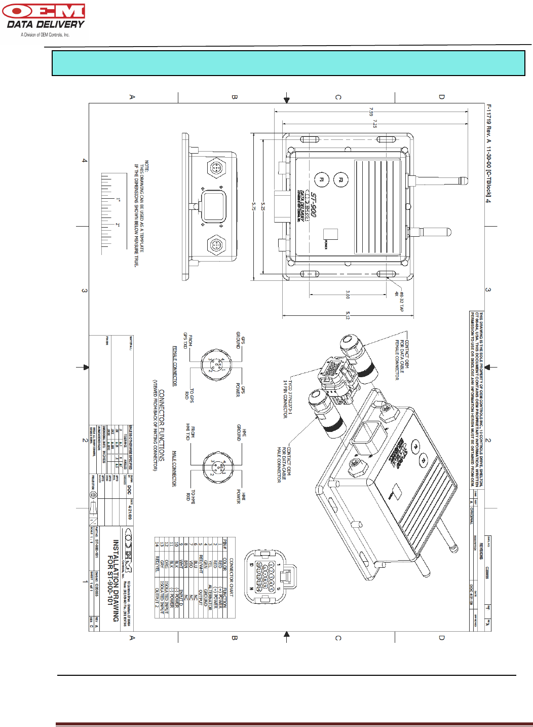
ST-900-100 EPW/1174 Standard
ST-900-101 EPW/1174 Standard and Computer Connection
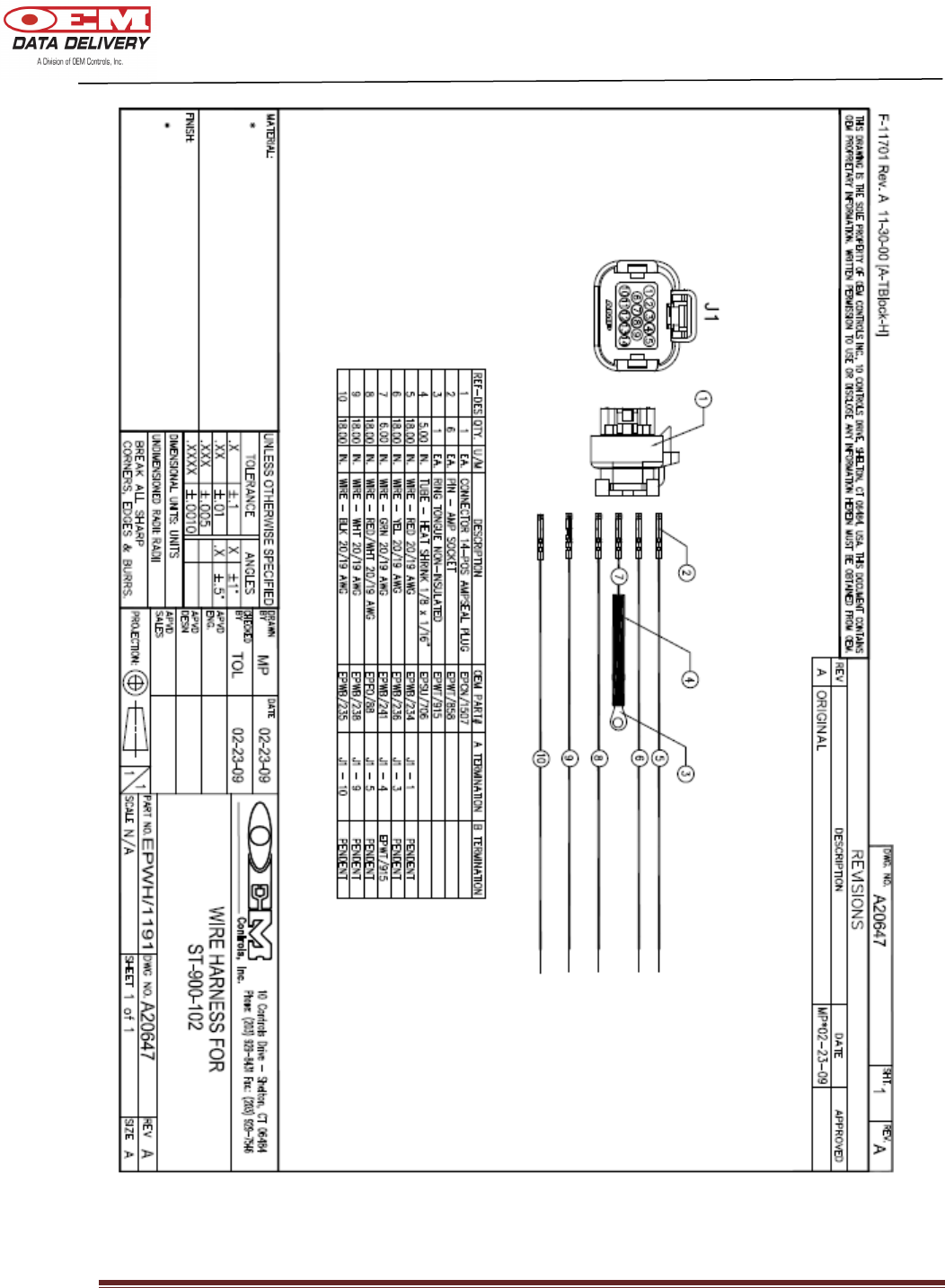
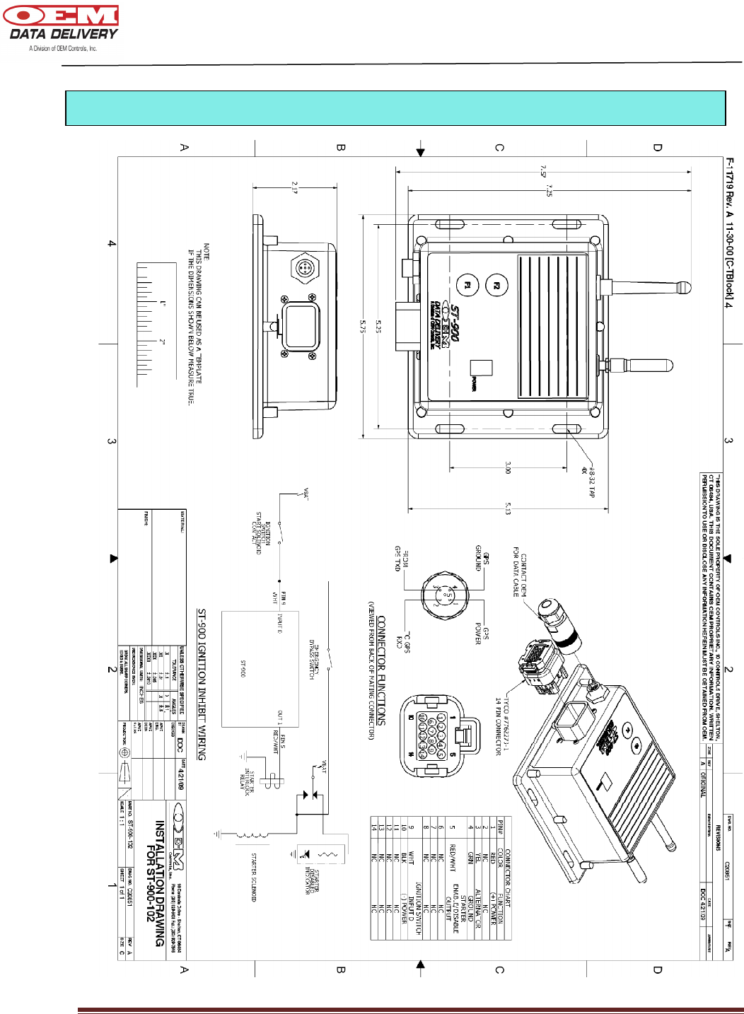
ST-900-102 EPWH/1191 Standard and Remote Starter Disable (RSD)
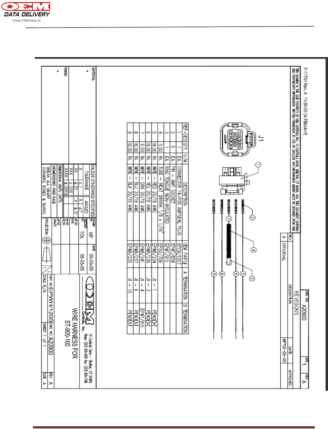
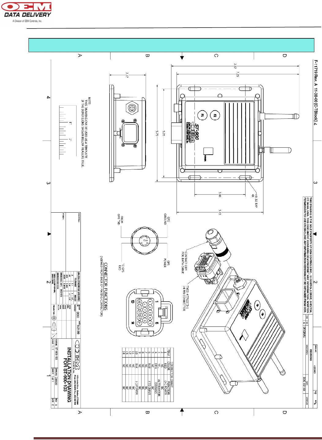
ST-900-103 EPWH/1200 Standard and Data Logs
The next few pages will display schematics of each of these models.
ST
-
900 Models
Available
DOC # 20977
ST-900 Installation Guide and User’s Manual Page 6
DOC # 20977
ST-900 Installation Guide and User’s Manual Page 7
DOC # 20977
ST-900 Installation Guide and User’s Manual Page 8
DOC # 20977
ST-900 Installation Guide and User’s Manual Page 9
Electrical Installation
DOC # 20977
ST-900 Installation Guide and User’s Manual Page 10
Electrical Installation
DOC # 20977
ST-900 Installation Guide and User’s Manual Page 11
Electrical Installation
DOC # 20977
ST-900 Installation Guide and User’s Manual Page 12
Electrical Installation

DOC # 20977
ST-900 Installation Guide and User’s Manual Page 13
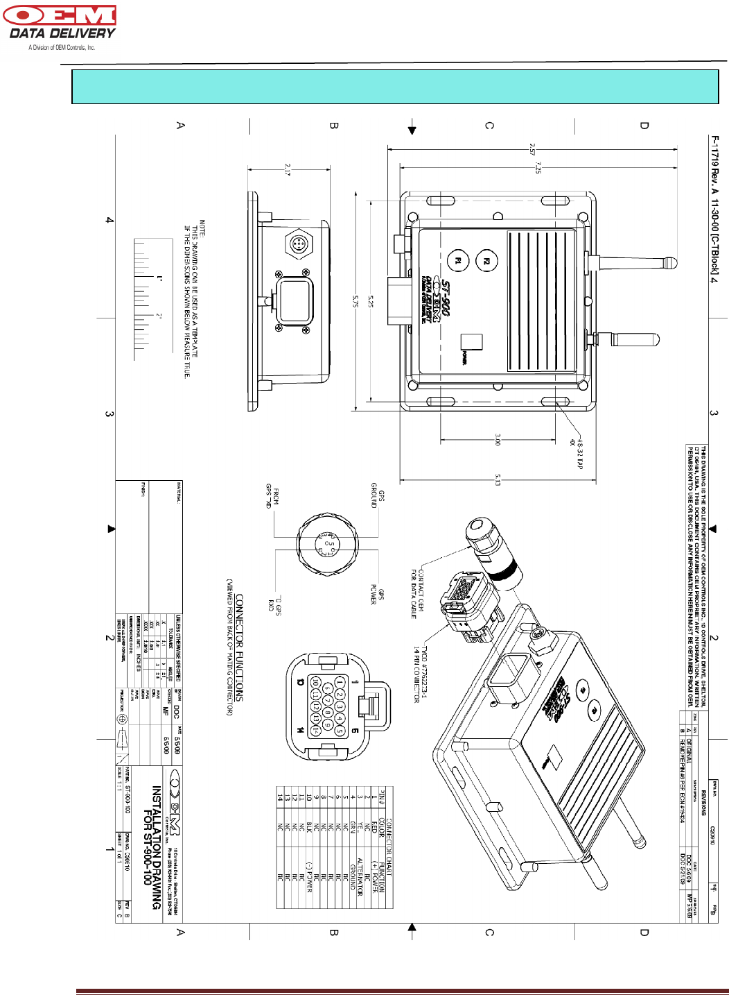
1. Turn off motor. Also turn off master switch, if so equipped.
2. Mount ST-900 near fuel refill area.
3. Wire Color:
RED – Connect RED wire to a positive 12V or 24V DC source. Provide a 3 or 5 amp fuse
at the battery
BLACK – Connect BLACK wire to ground on battery
GREEN – Connect GREEN wire to a chassis ground (e.g., frame, body, engine or frame
side of the master switch).
YELLOW – Connect YELLOW wire to a positive 12V or 24V power source that ONLY has
voltage while the machine is running (must be on alternator “R” DC terminal in
order to get both work and idle reading or yellow wire to output of Vibe Sensor)
(ST-103).
Note: 7.0 volts is the minimum “motor run” voltage (starts the Service Tracker counting hours).
4. Calibrating your ST-900 for Engine Work and Idle Logging:
Step 1: Start the equipment and keep it idling.
Step 2: PRESS & HOLD the “F1” button on your Service Tracker.
Step 3: Release the “F1” button after the display cycles from F to C to F for, about
10 to 15 seconds. If you don’t get a C during calibration, check the connection
of your yellow & green wires.
Note: If the equipment does not have a pulse (RPM) output, the ST-900 display will
cycle F to C to n (no pulses) to F. In this case, there will be a Run Log.
Note: The ST-900 will generate run logs, if the yellow wire connected to 12 V or 24
DC.
Note: If the yellow wire is connected to the “R” terminal of alternator and the
alternator is giving pulsed outputs, the tracker will generate idle and work
logs.
Note: If the yellow wire is connected to an ST-103 (Engine Vibration Sensor) you
will be able to obtain work logs.
5. Diagnosis:
1. If the motor is OFF, and the master switch is ON and there is a fast-pulse** - re- check
the yellow wire connection location.
2. If the motor is ON, and the master switch is ON, and there is a slow-pulse* - re-check
the there is a yellow or green wire connection.
** Fast Pulse - LED flashes once every two seconds
*Slow Pulse - LED flashes once every four seconds
3. If the Service Tracker will not turn on or wake, check the red wire and the fuse. Use a
voltmeter to check the red and black wires at the Service Tracker. Re-check the power
wiring if there is not 12 (or 24) volts present.
Installing an ST-900 Cellular Service Tracker

DOC # 20977
ST-900 Installation Guide and User’s Manual Page 14
4. If the motor is OFF, and the master switch is OFF, and there is fast-pulse** - separate
the green and black wires and connect the green to a chassis ground.
5. Make sure you don’t split the batteries when they are jumped (e.g., two 12V
batteries to get 24V).
** Fast Pulse - LED flashes once every two seconds
*Slow Pulse - LED flashes once every four seconds
6. Completion:
1. Observe the Service Tracker:
1. If the alert light flashes at one second intervals, then it is counting hours.
2. If the alert light flashes at three second intervals, then it is NOT counting hours.
7. Installation Tips:
1. Identify the frame voltage (i.e., positive ground or negative ground).
2. Avoid routing wires near moving parts. Give adequate slack in wires. Zip-tie all wires.
3. Avoid routing wires near hot exhaust system and turbo chargers.
4. When mounting Service Trackers, watch out for compartments that open,
especially bob cats or other skid steers where the radiator assembly lifts up, so
leave slack in wires to the Service Tracker.
5. Do not drill mounting holes unless you are confident that you will not damage the
underlying component.
DOC # 20977
ST-900 Installation Guide and User’s Manual Page 15
ST
-
900 Cellular Service Tracker
*
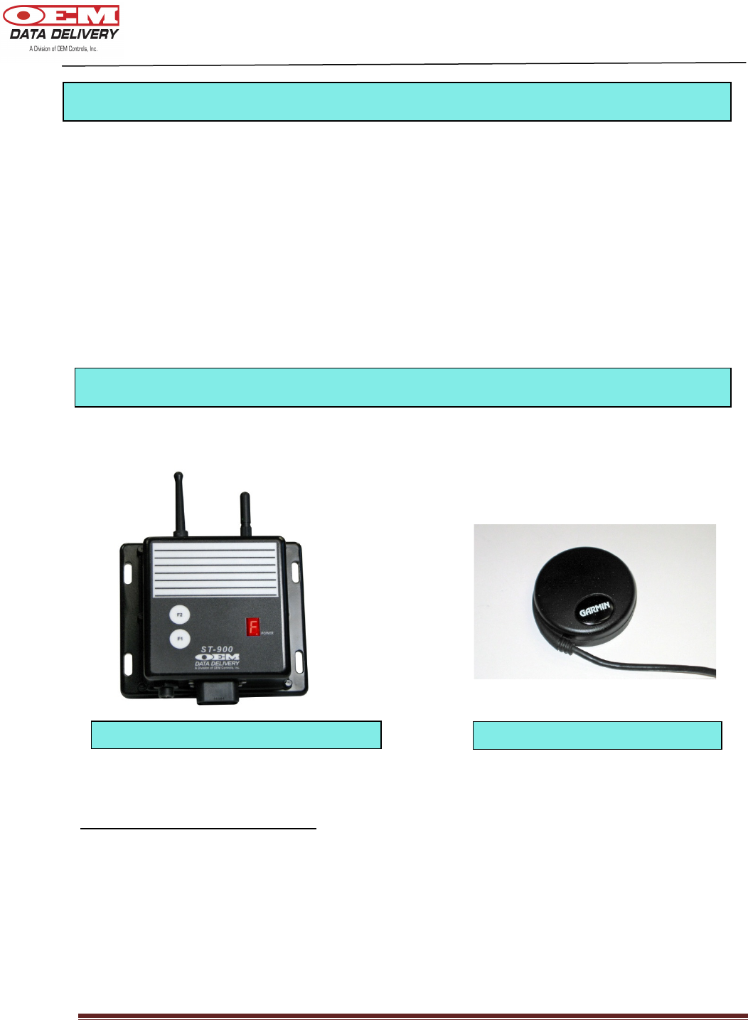
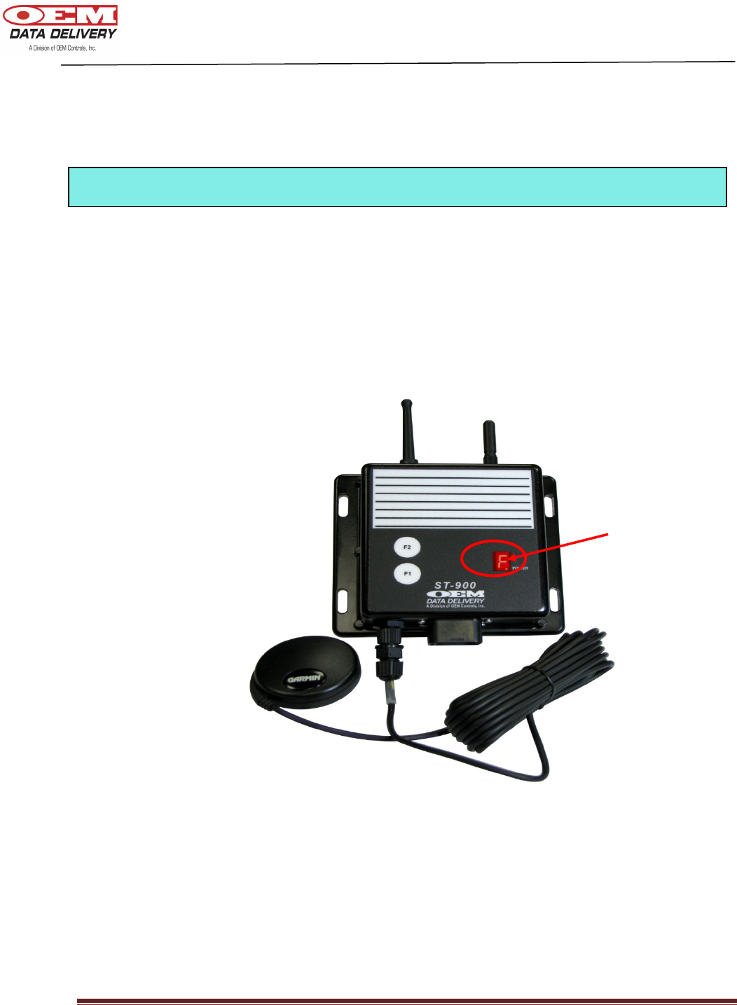
1. Plug the GPS module into the connector located beside the main harness connector. Make
sure the key on the connector is aligned before you fasten it securely.
2. Turn the vehicle ignition on. (The power to the GPS is turned off when the ignition is off to
conserve battery power). The GPS module will need about 5 minutes to get a valid fix for the first
time.
3. Depress “F2” for diagnostics. There should be no “G” displayed when your GPS is fully
functional.
Cables (Part #’s for Reorder)
EPWH/1174 – Main Cable (Service Tracker)
P-19779 – GPS Antenna replacement
*Actual ST-900 may differ slightly from that pictured
GPS Antenna
Installing the GPS
Equipment Needed to Operate your ST-900

DOC # 20977
ST-900 Installation Guide and User’s Manual Page 16
• Radio Terminal Downloader
• Travel logs are logged 10 times per hour while the vehicle is in motion
• Work/idle/run logs, count/duration logs
• Cumulative Machine Hours (CMH)
• 7 User Programmable Service Alerts (Maintenance) (Turned off by default)
• GPRS communication for remote connectivity
• Power conservation (GPS turns off when ignition is off). GPRS modem turns off when
vehicle battery is low and 2 low messages have been transmitted to the server.
• SSI starter solenoid inhibit option - GPRS only
• Update Cumulative Machine Mileage using Aceeca (PDA)
• Radio connectivity for GoPod/Aceeca
ST
-
900 Features
DOC # 20977
ST-900 Installation Guide and User’s Manual Page 17
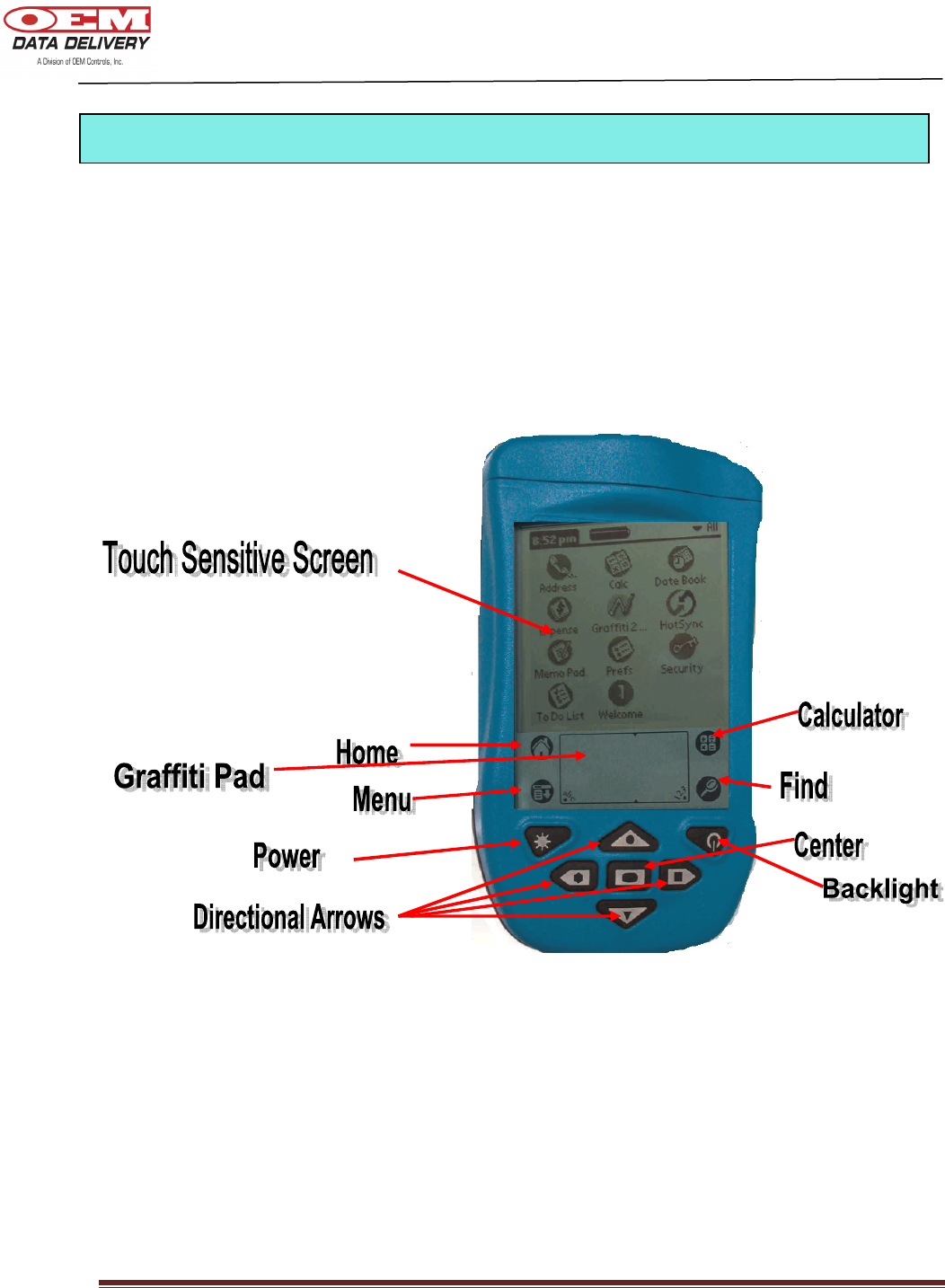
The Aceeca can be used to program your ST-900 profile. You will be able to assign a unique
equipment number and description to each of your ST-900’s. You can program service alarms
to remind you of your machine maintenance. With the ST-900 you will be able to program up to
seven service alerts. Some of the features of the PDA you should be familiar with include the
power button, the touch sensitive screen, the directional arrows, and the graffiti pad, as well as
the infrared port.
The part number for ordering an Aceeca is STP/MEZ1000/RMA.
Programming the ST-900 with the Aceeca PDA

DOC # 20977
ST-900 Installation Guide and User’s Manual Page 18
1. On your PDA:
• Plug the Primary Radio Antenna into the PDA
• Press “ POWER”
• TAP “Home”
2. TAP “Equipment Setup” on your list of programs
3. TAP “Radio” to be sure your PDA is in Channel 2
4. TAP “Setup”
5. TAP “New Profile”
6. TAP inside the Equip# box to enter your Equip#. Choose your number from the list or to
enter a new Equip #, TAP “Edit”, then TAP “New”. TAP “keyboard” and enter your Equip
#, then TAP “Done”.
7. TAP on the second line and enter your new Description by tapping “keyboard” and
entering your description. TAP “Done”, then TAP “OK”.
8. TAP inside the first Service Box to enter your Service Tags. (This will display the Tag Edit
Screen).
9. On the Tag Edit screen enter your service description using your ABC-123 Graffiti Pad and
TAP “Done”, then TAP “OK”. (You may program as many as seven different services.)
10. TAP on the “0” under “Actual” to program your actual hours. (This will display the Actual
Hours Edit screen).
11. Program your actual hours using the ABC-123 Graffiti Pad and TAP “Done”, then TAP
“OK”. (Use the same process to set all other actual hours).
12. To program your Scheduled Hours, TAP to the left of the number. Use your ABC-123
Graffiti Pad to program your scheduled hours and TAP “Done”.
13. Enter the total number of hours the machine has been operating into the “Cumulative
Machine Hours” field by tapping to the right of Cumulative Machine Hours and using your
ABC-123 Graffiti pad. TAP “Done”.
14. Enter timeout value by tapping to the right of the “Timeout” field. Using your ABC-123
Graffiti pad enter your “Timeout” value. TAP “Done”, then TAP “OK” at the bottom left of
the “New” Screen when you are done setting up your profile.
15. The Write Warning screen will appear.
16. TAP “OK”.
Setting an Equipment Profile
DOC # 20977
ST-900 Installation Guide and User’s Manual Page 19
17. The “Set Up” screen will appear, which means your profile is ready for uploading onto the
ST-900 Service Tracker. (There will be two arrows above the Com-Link button).
1. Hold the “F1” button on your Service Tracker until it switches to Channel 2 (fuel mode).
There will be an “F” in your power window. The “Alert” button on your Service Tracker will
flash quickly.
2. On your PDA, TAP “Radio”, then TAP “Com-Link”. Your PDA will now be in the Setup
screen and the two arrows above the Com-link button will be facing downward. You are done
programming your Service Tracker.
Alert Light
Loading your Profile onto the Service Tracker

DOC # 20977
ST-900 Installation Guide and User’s Manual Page 20
You will be able to diagnose your ST-900 using your PDA. You can retrieve information about
your ST-900 such as your software part number, serial number, ICCID number (Cellular Modem
I.D.), and modem firmware version number. It will also display the state of your battery, GPS
and GPRS communication status. You will also be able to retrieve information such as the
serial number, latitude, longitude, cumulative machine mileage and cumulative machine hours.
The following is the procedure:
1. On your PDA:
• Plug the Primary Radio Antenna into the PDA
• Press “POWER”
• TAP “Home”
2. TAP “Equipment Setup” on your list of programs
3. TAP “Load” in the upper left hand corner of the screen
4. TAP “Info” on the upper right hand corner of the screen
5. TAP “Diag” on the drop down menu
6. On your ST-900 press and hold “F1” for about 3 seconds to switch to channel 2
(an “F” is displayed)
7. On your Aceeca TAP “ST-900”
8. TAP “Diagnostic” or “GPS” depending on what you would like to see information about
Diagnosing
the
ST
-
900
DOC # 20977
ST-900 Installation Guide and User’s Manual Page 21
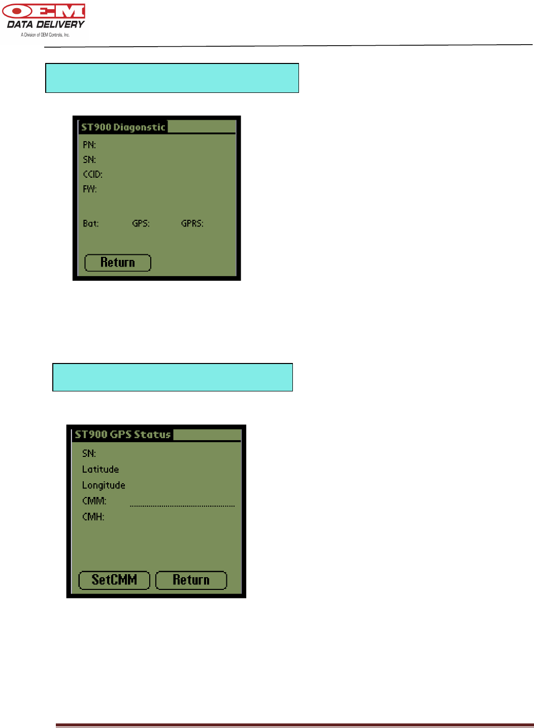
This screen will display your part number,
serial number, cellular modem identification
number, firmware version number, the state
of your battery, GPS and GPRS
communication.
This screen will display your serial number,
latitude, longitude, cumulative machine
mileage and cumulative machine hours.
ST-900 GPS Status Screen
ST-900 Diagnostic Screen

DOC # 20977
ST-900 Installation Guide and User’s Manual Page 22
• Zinc Casting – Water resistant to IP67
• Voltage: 12 to 24 V (Range: 8-32 V)
• Memory - 256K bytes of program memory, 15K bytes of RAM; 128K bytes of external
EEPROM
• Storage – 34 days history each for idle/work/run/count/duration logs in external non-
volatile EEPROM when configured as daily logs, when configured as hourly logs, the
history is user specific
• 7 Segment Display for alarms display, GPS/GPRS communication diagnostics, fuel
mode, radio GPRS and connection status
• Real Time Clock (RTC) for time stamped data
• 2 push buttons (F1, F2):
F1 - used for calibrating ST-900 and radio channel switch during fuel mode
F2 - used for diagnostic purposes
• Operational temperature range -40°C +70°C
• Warranty: Standard 2 year warranty
• GPS : Serial connection to ST-900
• Cellular – dual band, GPRS, AT&T, normal operating frequency (824.2 – 848.8 MHz)
• Radio – 802.15.4 physical layer, normal operating frequency (240.5 MHz)
• Harness – Power (8 – 32 v DC), ground, ignition, 6 digital inputs, 2 digital outputs (1A,
Max)
• Data Logs – 2 optically isolated digital inputs, 4 standard digital inputs, Idle/work/run
logs, duration/count logs
• Travel Log – GPS latitude, longitude, incremental time log and Delta CMM (Cumulative
Machine Mileage)
• Data Format – Comma-Separated Value (CSV), Extensible Markup Language (XML),
Open Database Connectivity (OBDC), and others
Technical Specifications
DOC # 20977
ST-900 Installation Guide and User’s Manual Page 23
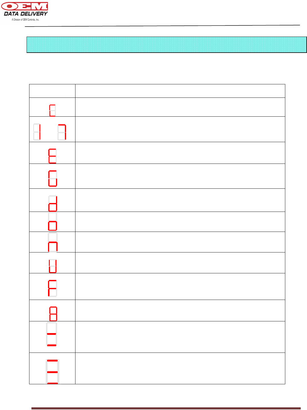
Your “power” window will display the following messages:
DISPLAY
MEANING
Calibration (when F1 is depressed for about 10 seconds)
thru
Service Alarms (turned off by default)
GPRS Cellular Error (anytime when not on network)
GPS Error (displayed when GPS has no fix or power to GPS has been
turned off or GPS malfunction)
Entering Diagnostic Mode (Active ONLY after unit is calibrated)
GPS and GPRS communication ok
No pulses detected during Calibration
-
New
,
Un
-
Calibrated
and ignition on
- For 1 second ignition on-off backup to Non
Volatile Memory
Fuel Mode – Channel 2 (operating frequency – 2410 MHz when “F1” is
depressed for about 3 seconds
Radio/Serial Terminal Downloader mode – Radio operating channel is 6
Engine Idle - Displayed only after calibration is complete and engine is
idling
Engine Work - Displayed only after calibration is complete and engine is
working
Seven Segment Display (Service Alerts, Diagnostics, Channel)

DOC # 20977
ST-900 Installation Guide and User’s Manual Page 24
User Notes:
DOC # 20977
ST-900 Installation Guide and User’s Manual Page 25
If you have any questions regarding this product,
we will be happy to
assist you.
OEM Data Delivery,
A Division of OEM Controls Inc.,
10 Controls Drive
Shelton, CT 06484
(203) 929-8431
Ask for OEM Data Delivery Support
Fax: (203) 929-3867
www.oemdd.com