OKAYO Electronics AT-200ID Audio Guide using 125kHz RFID technology User Manual
OKAYO Electronics Co., Ltd. Audio Guide using 125kHz RFID technology
User manual
AT-200iD-MT
Audio Guide
User Manual

Most users do not need a license to operate this wireless microphone system. Nevertheless,
operating this microphone system without a license is subject to certain restrictions: The
system may not cause harmful interference; it must operate at a low power level (not in
excess of 50 milliwatts); and it has no protection from interference received from any other
device. Purchasers should also be aware that the FCC is currently evaluating use of wireless
microphone systems, and these rules are subject to change. For more information, call the
FCC at 1–888–CALL–FCC (TTY: 1–888–TELL–FCC) or visit the FCC’s wireless microphone Web
ments and void user’s authority to operate the device.
Consumer Alert
site at http://www.fcc.gov/cgb/wirelessmicrophones.
Notice: The changes or modifications not expressly approved by the party responsible for
compliance could void the user’s authority to operate the equipment.
IMPORTANT NOTE: To comply with the FCC RF exposure compliance requirements, no change
to the antenna or the device is permitted. Any change to the antenna or
the device could result in the device exceeding the RF exposure require-
If this equipment does cause harmful interference to radio or television reception, which can
be determined by turning the equipment off and on, the user is encouraged to try to correct
the interference by one or more of the following measures:
—Reorient or relocate the receiving antenna.
—Increase the separation between the equipment and receiver.
—Connect the equipment into an outlet on a circuit different from that to which the receiver
is connected.
—Consult the dealer or an experienced radio/ TV technician for help.
This equipment generates, uses and can radiate radio frequency energy and, if not installed
and used in accordance with the instructions, may cause harmful interference to radio
communications.However, there is no guarantee that interference will not occur in a particular
installation.
NOTE: This equipment has been tested and found to comply with the limits for a Class B digital
device, pursuant to part 15 of the FCC Rules. These limits are designed to provide
reasonable protection against harmful interference in a residential installation.
Notice: The changes or modifications not expressly approved by the party responsible for
compliance could void the user’s authority to operate the equipment.
This device complies with Part 15 of the FCC Rules. Operation is subject to the following two
conditions: (1) this device may not cause harmful interference, and (2) this device must accept
any interference received, including interference that may cause undesired operation.

Preface
Thank you for the purchase of Audio Guide AT-200. This user manual contains
comprehensive instructions and operation of the unit, please read it over
before your use for the first time.
Features
High fidelity DSP technology, offering up to 20 hours stereo audio playback
with built-in 2GB memory card.
Access audio content through built-in speaker or external earphone jacks.
2 earphone jacks available for couple or kids and parents.
Backlit display and keypad for ease of use.
Raised dot 5 for visual impaired people.
Chargeable. Audio Guide can be recharged with chargers. Each charge can
run operation up to 12 hours.
Fast audio content update through Audio Master and Audio Guide Uploader.
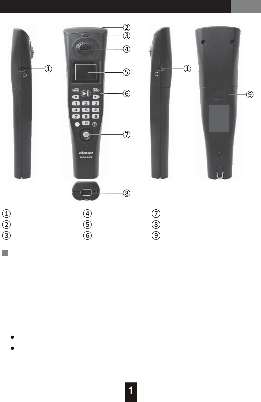
AT-200 Audio Guide
Earphone jack
Triggering module
Charging indicator
Inbuilt speaker
OLED screen
Keypad
Power/Stop button
Uploading/Charging connector
Battery door
Illustration
1. Earphone jack, stereo, 3.5 mm
1 or 2 headphones are valid for more than 1 user.
2. Triggering module
In addition to inbuilt IR triggering mode, various triggering options (RFID/RF/
GPS) are offered respectively upon demands.
3. Charging indicator
Glittery red LED indicator means potentially defective battery inside.
Please hand over the audio guide to the counter.
Red/Green LED indicator stands for charging/fully charged status.
AT-200 Audio Guide
7. Power/Stop button
4. Inbuilt speaker
Users can listen to audio commentaries through the inbuilt speaker. However,
this function will be disabled when the player connects with headphones.
5. OLED screen
Triggering modes, battery status, volumes, photos of exhibits, and playing
tracks/progress will display on the OLED screen.
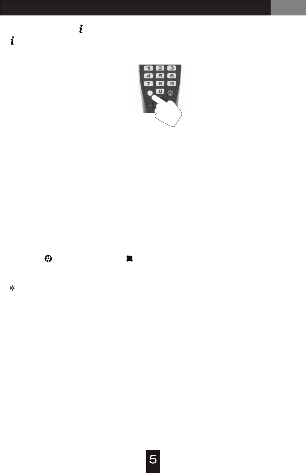
6. Keypad
Numeric buttons
for audio tracks Fast forward, next track
Fast backward, last track
Play & Pause Volume up
Volume down
NOTE: 2 auxiliary buttons, and , are designed for further information
and will be updated by organizers.
To power on - press power button for about 1 second.
To power off - press power button for about 2 seconds till “OFF” shows up.
To stop or redial codes of an audio commentary, simply press stop button
and dial new codes again.
9. Battery door
If the inbuilt battery is failed, open the battery door for replacement.
8. Uploading/Charging connector (IEEE 1394 port)
This port will be connected with uploaders/chargers for either uploading or
recharging.

AT-200 Audio Guide
Operation
Power ON/OFF
Press and hold power button for 1 second until a beep to power on.
Press and hold the button for 2 seconds until an OFF sign shown in display
and beeps twice to power off. (* Alarm is still working even audio guide is off.)
Auto Power OFF
When audio guide is not operated for 30 minutes (factory default), it will switch
off automatically. (* Alarm is still working.)
Auto Power Off can be changed or defined through software “Audio Master G2”.
Automatic audio play is only working with specific devices : IT-200, RT-200,
iD-200, which are optional on demand.
Choose Language
Change and choose a desired language by entering 3 number codes with # and
press to activate. A prompt audio and display will give assistive information
to your change when the change is successful. (Language code is available from
951 to 982. 951 is the factory default.)
Manual Play and Auto Play
There are two ways to activate a picked audio content – manually or automatic-
ally. In manual mode, the audio content shall be activated with a 4-digit number
code and play . (Number code is available from 0001 to 9999.) In automatic
mode, when an audio guide is in the service coverage, the number code will show
up in display and audio content will be played automatically. (* Semi-automatic
mode is available in Audio Master G2)
Delete Number Code
When a wrong number code is entered, simply press STOP key to delete it and
then enter correct number code again.
AT-200 Audio Guide
Access to additional audio content ( level)
Plan a programmed tour
Audio contents for level can be defined in Audio Master G2.
You can listen to additional audio content for a particular track by simply pressing
key during the playback and then entering required number code. To exit from
level, press key again after the additional audio content stops playing.
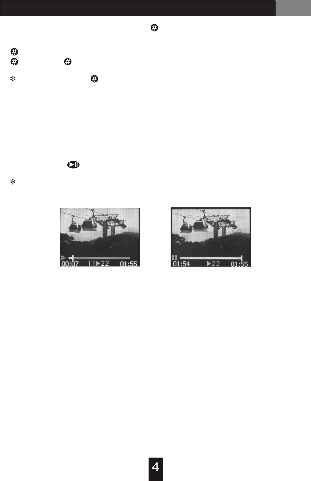
Visitors can follow a pre-programmed audio map to simplify their trips. If this
programmed tour is designed, an arrow symbol will show up between 2 track
numbers underneath. Take images below for example, track 22 will be the next
audio commentary after track 11 and when track 11 plays to the end, visitors can
press play key ( ) to enter track 22 directly.
(▶)
This function can be defined in Audio Master G2.
AT-200 Audio Guide
Information key “ ”
key is served as default information. It can be audio and/or picture format.
Battery and Charge
When battery power is almost exhausted, a low battery icon will blink and
show in display. The audio guide will automatically switch off in 20 seconds.
Please allocate it onto charger as soon as possible.
Alarm
IR Triggering
When alarm is performed at audio guide, it will generate a continuous beep.
The audio guide will be locked and can’t be operated as a result. Please press
and hold key and then press key to escape from alarm status. When audio
guide is released from alarm status, it can be operated as usual.
Useful tips: use alarm trigger LT-200 to release audio guide from alarm status
or restore audio guide by putting on charger.
This audio guide is built with IR triggering function. To make it possible, you will
need to install an infrared trigger IT-200 (optional).
1
1
2
2
3
3
6
6
7
7
8
8
10
10
9
9
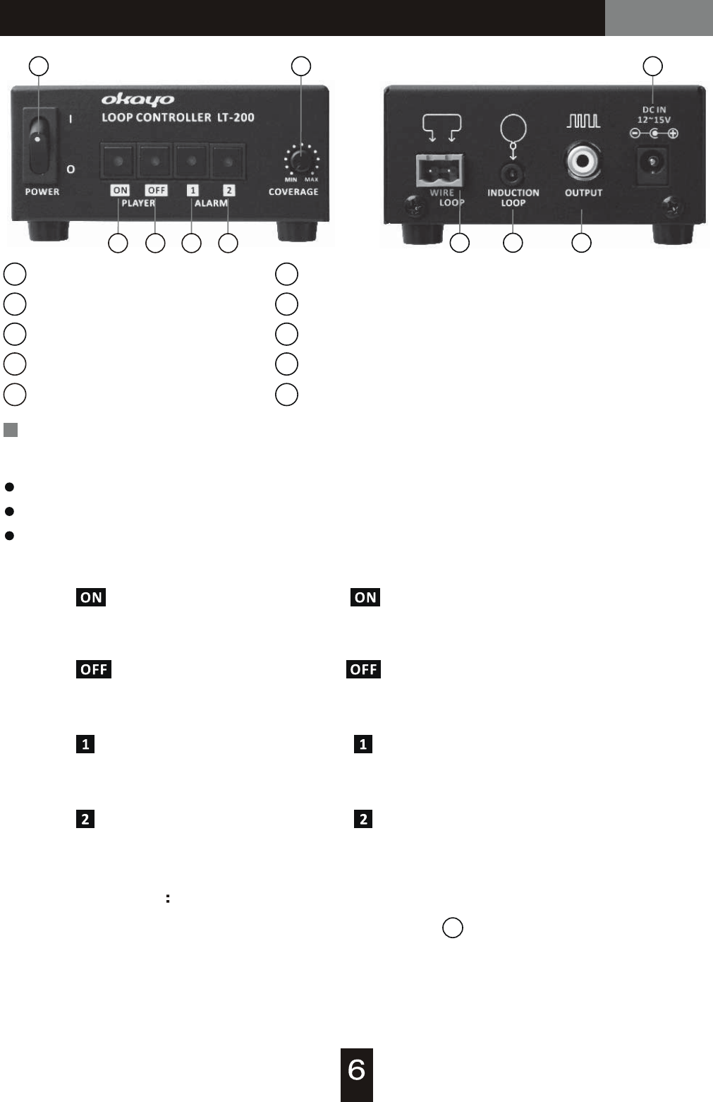
Power switch
Player ON button
Player OFF button
Alarm 1 button
Alarm 2 button
Coverage (trigger) adjustment
Loop antenna connection
Induction loop connection
Output connection, for loop amplifier
Power input socket (DC IN)
4
4
5
5
Connect power supply with the device well.
Build a triggering zone with supplied loop wire (plea se refer to installation example).
Switch power on and set a desired triggering function.
Operation
Installation
PLAYER : press and hold ON button for 2 seconds until LED lights in RED to
activate. This function will force every audioguide within triggering
range to power ON.
PLAYER : press and hold ON button for 2 seconds until LED lights in RED to
activate. This function will force every audioguide within triggering
range to power OFF.
Triggering Function
ALARM : press and hold ON button for 2 seconds until LED lights in RED to
activate. This function will force every audioguide within triggering
range to beep.
ALARM : press and hold ON button for 2 seconds until LED lights in RED to
activate. This function will force every audioguide within triggering
range to beep.
Coverage Adjustment
Adjust triggering range with coverage adjustment to accommodate different
zone or application, such as service desk or lobby.
6
Loop Controller / Alarm TriggerLT-200 Alarm Trigger Optional
Loop Controller / Alarm TriggerLT-200 Alarm Trigger Optional
9
OUTPUT Connection
When the maximum triggering coverage can’t meet your requirement, you
can connect a loop amplifier with this device trough OUTPUT connection jack
to increase triggering coverage.
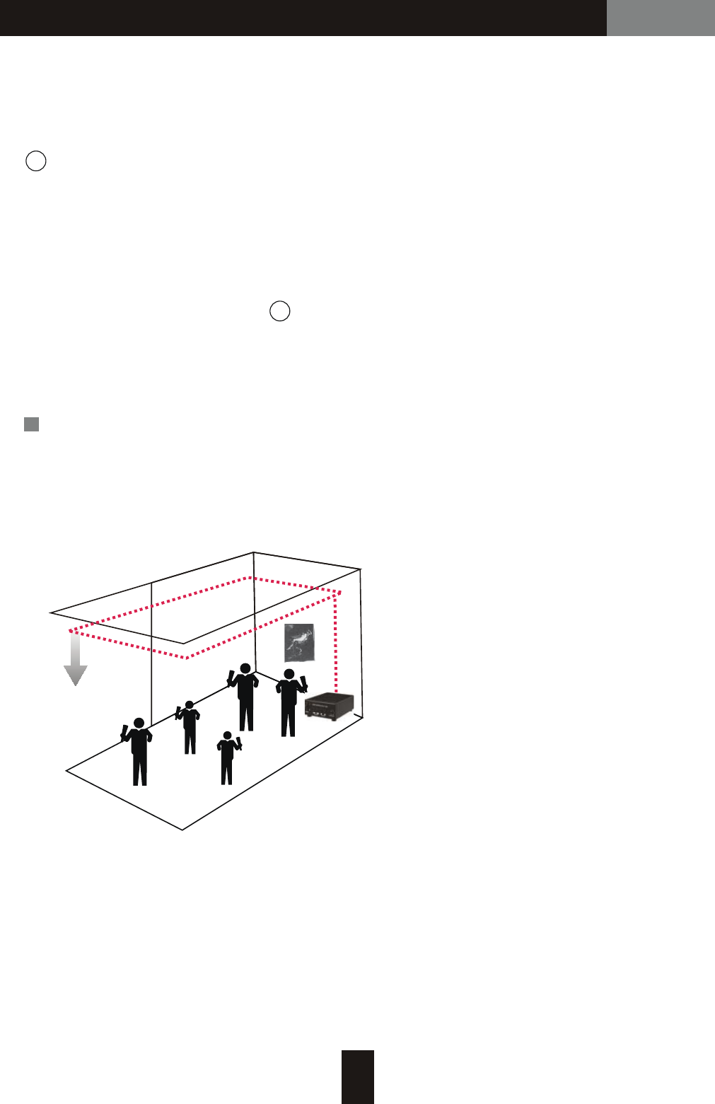
Installation of Loop Wire
Arrange a triggering zone with factory supplied loop wire is recommended. In
order to obtain better triggering performance, the supplied loop wire shall be
ran out completely.
8
Induction Loop Connection
For a small range triggering (< 30 cm), an induction loop is able to connect with
this device.
※
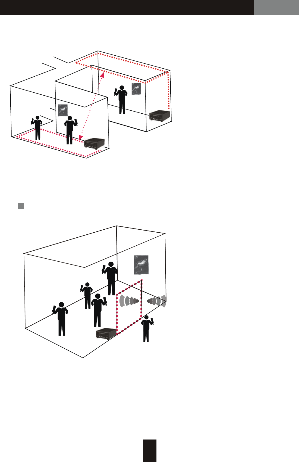
Example for antenna layout
In case two loop controllers are operated in same area, make sure each set
of antenna shall be kept away at 4 meters or more.
I. Single set antenna layout
triggering range at 2 m
7
Loop Controller / Alarm TriggerLT-200 Alarm Trigger
A
B
>4 m
II. Multiple sets antenna layout
Antenna A and B shall keep away from each other for at least 4 meters.
Example for allocation of antenna and alarm trigger
Audioguide will beep when it comes
close to alarm trigger within 2 m.
Optional
8
Loop Controller / Alarm TriggerIT-200 IR Trigger Optional
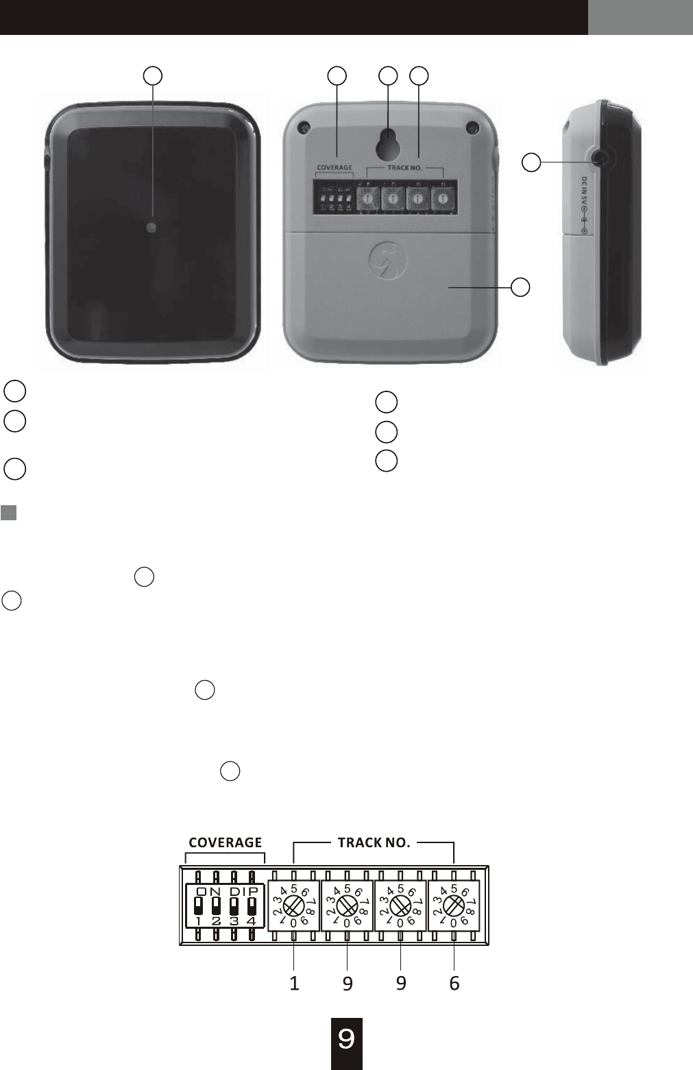
5
6
123 4
1
2
3
4
5
6
Power indicator
Power switches (DIP)
and power mode setup
Hanging hole
Track number setup
Battery door
DC input socket
Operation
Power On
1
2
Any DIP switch moves to ON position will turn this device on. Power indicator
will light up for 2 seconds and then off. Indicator will blink every 2 seconds when
device is working.
Power OFF
When all DIP switches move to OFF (downward) position, the device will be
turned off.
2
Track Number Setting
Tracking number is set by rotary switches, from left hand side to right hand
side. Every single IR trigger can activate one tracking number only. An example
(1996) is shown as below.
4
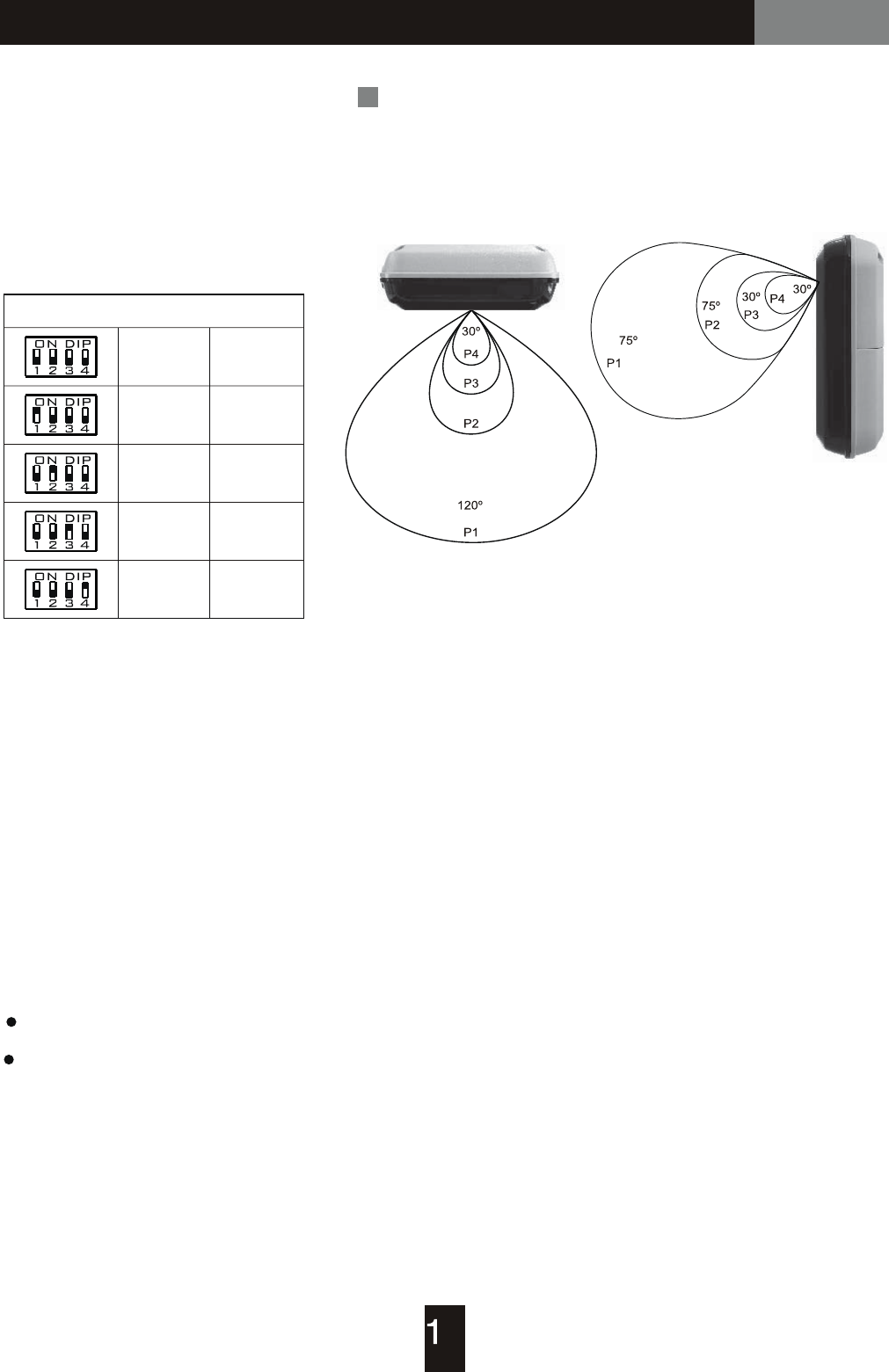
Loop Controller / Alarm TriggerIT-200 IR Trigger Optional
IR signal coverage on application
(Fig. 1) (Fig. 2)
COVERAGE setting
Set a desired IR triggering
range with DIP switch.
A table below gives all
possible settings and
respective functions.
P1 (Max coverage) > P2 > P3 > P4 (Min coverage)
P1
P2
P3
P4
OFF
ON
ON
ON
ON
OFF
DIP Status Power
Indicator blinks in Red = low battery
Indicator blinks in Green = sufficient battery energy or adapter employed.
※Adapter can't charge battery. When battery and adapter are employed at the
same time, this IR trigger will consume energy from adapter only.
Power Supply
Insert 2 AA batteries or connect with factory supplied power adapter (5V / 1A).
Power Indicator
0
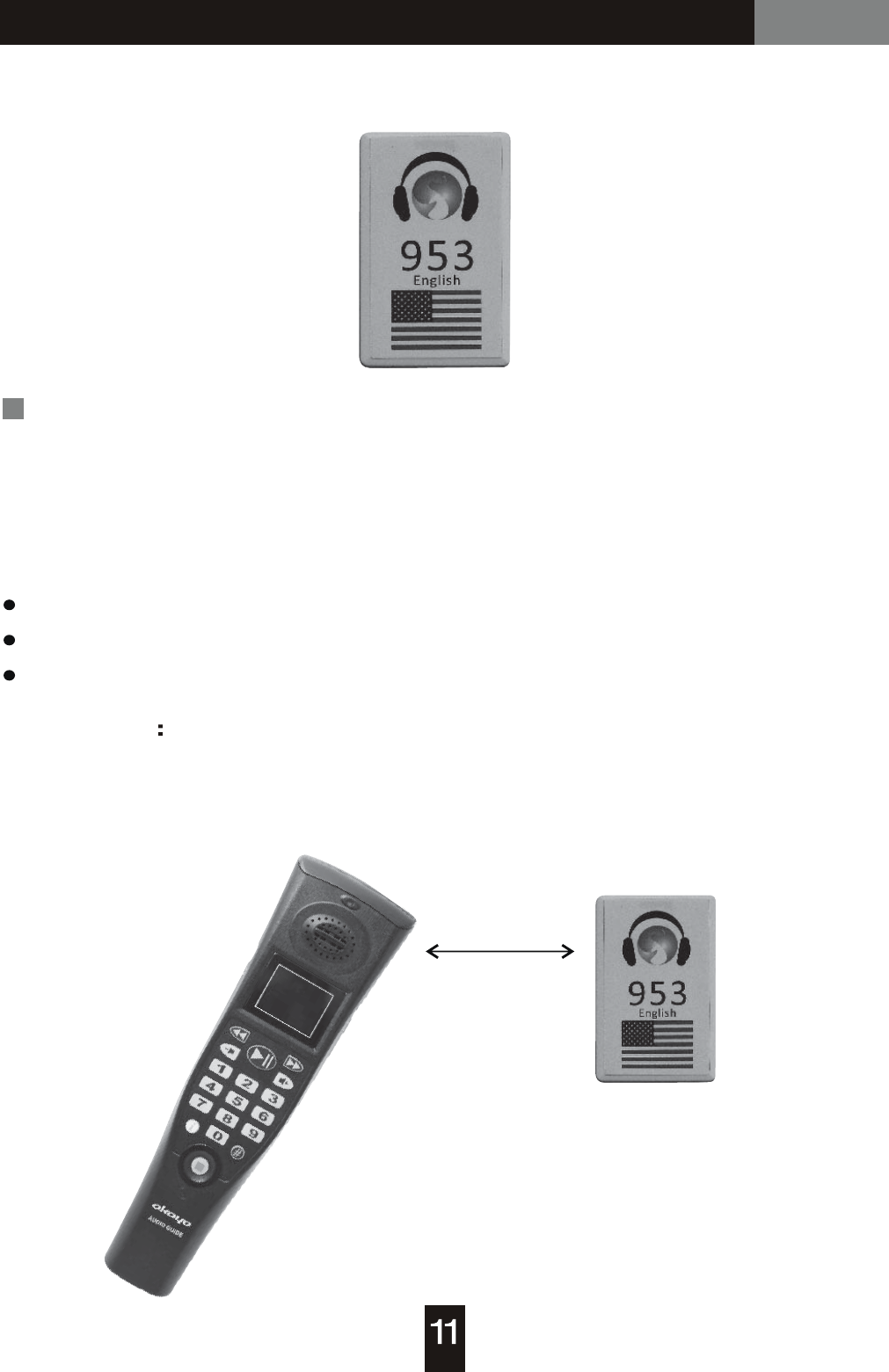
Loop Controller / Alarm TriggeriD-200 RFID Tag Optional
RFID (Radio Frequency Identification) Tag; Proximity Tag
How to operate
RFID (Proximity) Tag
Each tag can be programmed with one number code, from 0000 ~ 9999, through
RFID tag writer (optional). Following tips of number code are helpful to plan your
audio tour.
Auto Triggering
0000: served as “audio guide OFF”.
951 - 982: served as “language number code”.
0001 - 9999: served as “audio track number”.
Get audio guide close to RFID tag to obtain an audio number code automatically.
The audio guide will play accessed audio track automatically. Triggering range
in 5 cm is ideal.
< 5 cm

Caution / Troubleshooting / Maintenance
Caution
Troubleshooting
No Sound
No Picture
Failed to Turn ON
Maintenance
1. DON'T operate the device in the rain or in humid circumstance.
2. Prevent the device from dropping.
3. Employ factory supplied Li-Poly battery only, to prevent feasible damage
and danger.
4. DON'T tear battery apart in case it explodes.
5. Dispose battery with insulated package in case it explodes.
Make sure audio guide is uploaded / duplicated with audio content.
Make sure memory card is available in device.
Return audio guide to the dealer when you can't fix it with above check
points.
Make sure Li-Poly battery is available in device.
Return audio guide to the dealer when you can't fix it with above check
point.
Make sure audio guide is uploaded / duplicated with picture content.
Make sure memory card is available in device.
Return audio guide to the dealer when you can't fix it with above check
points.
1. Prevent operating audio guide in high temperature and high humidity for a
long time.
2. Charge audio guide at least 8 hours long, for first-time use.
3. Charge audio guide once a month when you don't use it for a long time.
4. Do not change Li-Poly battery by yourself. Contact your dealer for this
service.