OPENBRAIN Technologies M5G BLUETOOTH MODULE User Manual M5G
OPENBRAIN Technologies Co., Ltd. BLUETOOTH MODULE M5G
Users Manual
OPENBRAIN Technologies Co., LTD.
TEL : +82-31-596-6400 FAX : +82-31-596-6410
E-mail : obt@openbrain.co.kr
http://www.OPENBRAIN.co.kr
http://www.sonorix.com
Approval Sheet
for Product Specification
Re
f
.No :
Rev. No :
Issued Date :
Customer :
Product Name :
Model No. :
Customer Approval
Signature / Stamp
SBNTECH
Bluetooth Module
M5G
APS-2009-012
1.1
2009.5.23

2
OPENBRAIN Technologies Co., LTD.
Change History
Rev. Date Author Reason for Change
0.9 2008.5.26 S.H.Cho Preliminary Drafting
1.0 2008.6.18 S.H.Cho Antennae characteristics and reliability test data supplements
1.1 2009.5.23 Y.Y.Lim Change the Connector (SMD > DIP)
Internal Check/Approval
Author Checked by Approved by
Name Y.Y. L i m J . H . P a r k J . D. O h
Date 2009.5.23
Signature

3
OPENBRAIN Technologies Co., LTD.
Contents
1. SUMMARY ................................................................................................................................................ 4
1.1. PRODUCT SUMMARY .................................................................................................................................... 4
1.2. PRODUCT FEATURES .................................................................................................................................... 4
1.3. SPECIFICATIONS .......................................................................................................................................... 4
1.4. APPLICATION ............................................................................................................................................... 5
1.5. EXTERNAL APPEARANCE AND PIN (PAD) SPECIFICATIONS ................................................................................. 5
2. HOW TO USE ............................................................................................................................................ 7
2.1. HARDWARE DESIGN METHODOLOGY .............................................................................................................. 7
2.2. OPERATING PROCEDURES ............................................................................................................................ 7
3. PRODUCT SPECIFICATIONS .................................................................................................................. 8
3.1. ELECTRICAL SPECIFICATIONS ........................................................................................................................ 8
3.2. CURRENT CONSUMPTION ............................................................................................................................. 9
3.3. ANTENNAE RADIATION CHARACTERISTICS .................................................................................................... 10
3.4. MECHANICAL SPECIFICATIONS ..................................................................................................................... 13
4. PRECAUTIONS DURING HANDLING ................................................................................................... 14
4.1. GENERAL PRECAUTIONS ............................................................................................................................. 14
4.2. MAXIMIZING RF PERFORMANCE .................................................................................................................. 14
5. RELIABILITY TEST RESULT ................................................................................................................. 15
5.1. OPERATING AND STORAGE TEMPERATURE TEST RESULTS................................................................................ 15
5.2. TIME VS TEMPERATURE FOR OPERATING & STORAGE RELATIVE GRAPH .......................................................... 15
5.3. RADIO CHARACTERISTICS FOR EACH CHECK POINT ...................................................................................... 16
6. PACKAGING ........................................................................................................................................... 20
7. PRODUCT SETTING (CUSTOMIZATION) ............................................................................................. 21
8. FCC Information …………………………………………………………………………………………….. 22
4
OPENBRAIN Technologies Co., LTD.
1. Summary
This document defines the product specifications of Bluetooth voice communication module (M5G)
including electrical and mechanical characteristics manufactured by OPENBRAIN for customer approval
purposes.
1.1. Product Summary
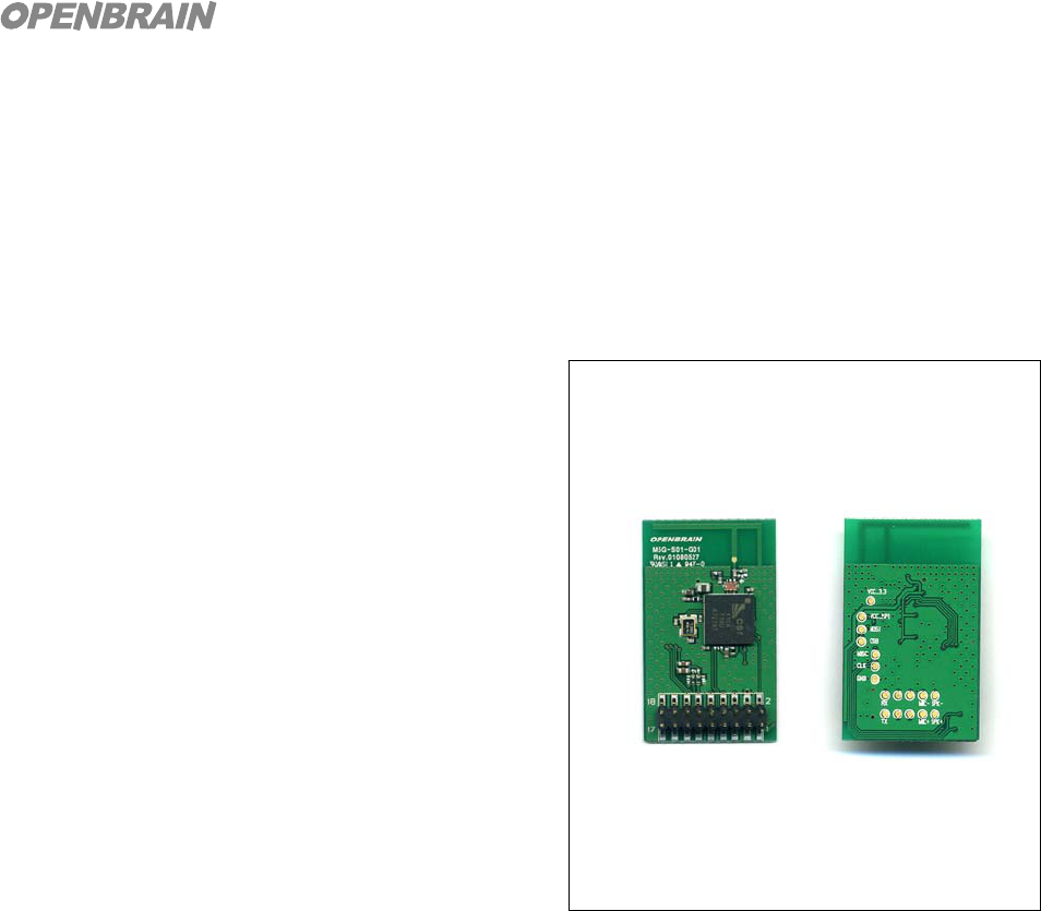
OPENBRAIN’s M5G is a compact Bluetooth
module designed to provide easy Bluetooth audio
application for communication devices without
Bluetooth functionality. By integrating the module
into communication devices that use
speaker/microphone or wired ear-sets, it enables the
communication device to be used with Bluetooth
headsets within a range of 10m distance.
M5G integrates all the functions needed to
replace existing audio connection wirelessly and has
been designed such that it is possible to control and
monitor the functions externally via serial (UART)
communication thereby enabling Bluetooth
functionality to be implemented into devices in a
short period of time. Also, the module has been designed to be ultra-small and light with minimal power
consumption thereby making it ideal for integration without sacrificing electrical and mechanical design
factors of existing devices. The advantages of using M5G are, it makes production easy and simple as
the modules are RF tuned and tested before supply and it is not necessary for customers to secure
additional Bluetooth test/measuring equipments.
1.2. Product Features
Wireless application possible without having to change circuit or software of existing
communication devices
Built-in antennae eliminates the need for separate antennae
Control of all functions and state monitoring via UART communication
Can be customized according to customer requirements
1.3. Specifications
Bluetooth V2.0, 1.2, 1.1 compatible
Frequency Band : 2,400 ~ 2,483 MHz
Embedded Protocol : L2CAP, RFCOMM, SDP
5
OPENBRAIN Technologies Co., LTD.
Embedded Profile : Handsfree AG
Output Power: 0dBm (Power Class 2)
Receiver Sensitivity : < -80dBm
Max. Data Rate : 702kbps
Antennae Gain: 0dBi Max.
Voice Signal Interface: Analog Single Ended or Differential
Host Interface: UART (1.8V Level, 115,200bps).
Operating Voltage: 3.3V
Operating Temp: -25 ~ +85℃
Size: 22.0mm X 36.0mm X 8.4mm
1.4. Application
Mobile phones, Video phones, VoIP phones
Other Voice Communication Devices
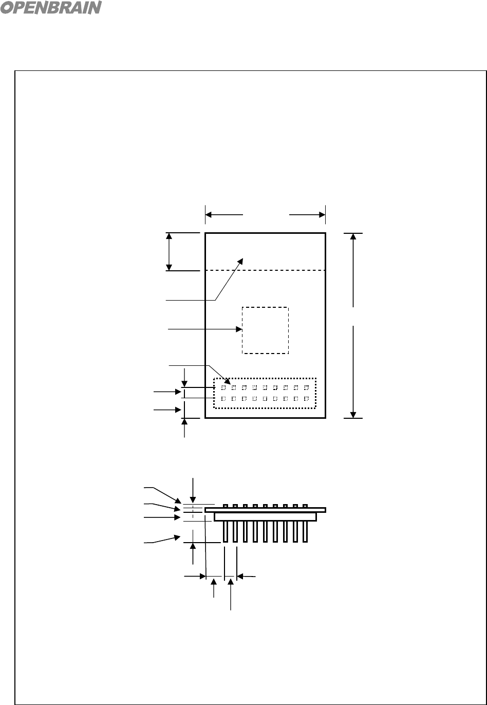
1.5. External Appearance and Pin (Pad) Specifications
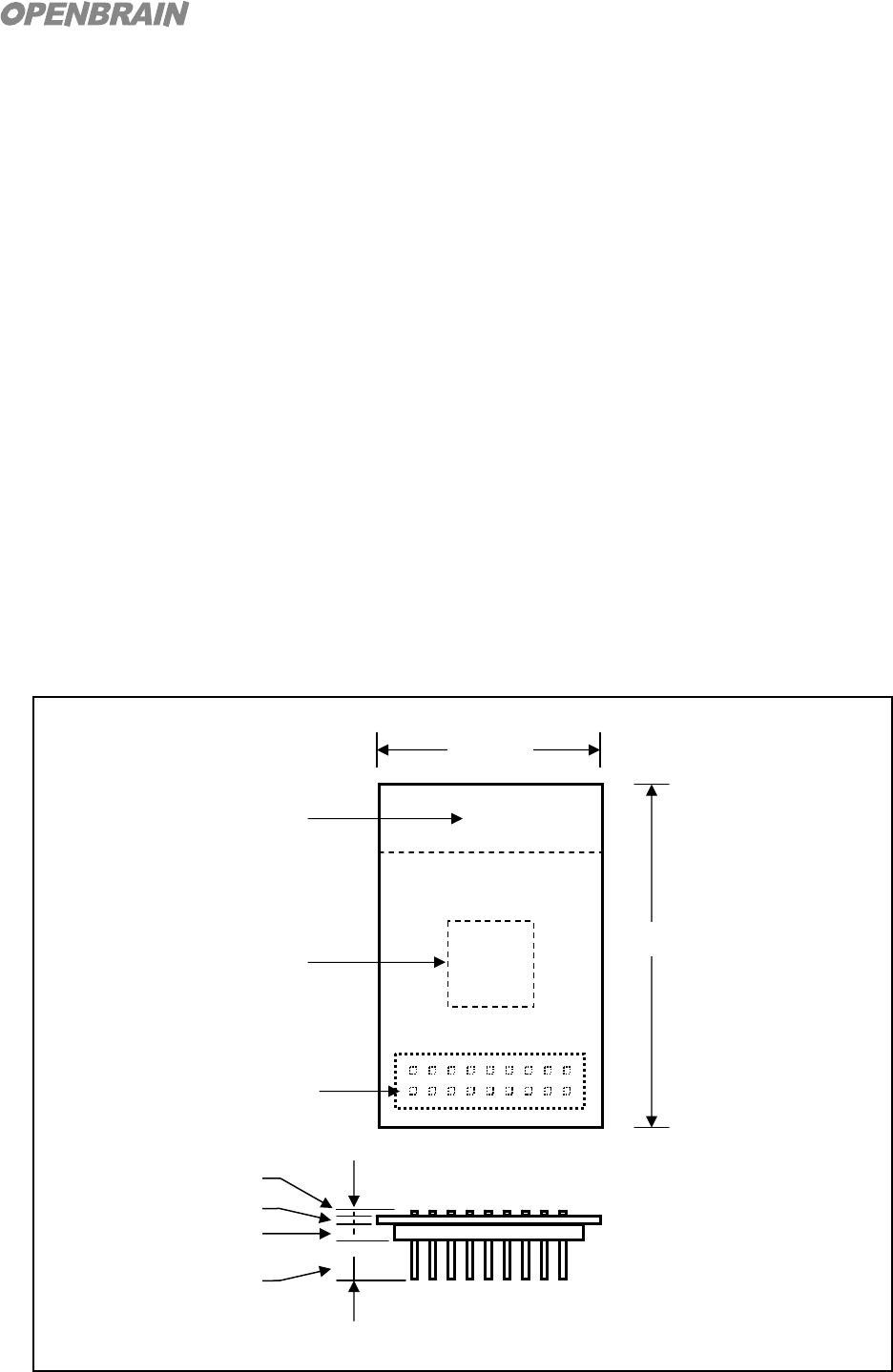
Mechanical Layout
* For mechanical part details, refer to 3.4
36.0 ± 0.3
22.0 ± 0.3
2 4 6 . . 18
1 3 5 . . 17
Connecto
r
Bluetooth Chip
Antenna
1. VDD
2. RESETB
3. GND
4. GND
5. UART_TX
6. UART_RX
7. PCM_OUT
8. PCM_SYNC
9. PCM_IN
10. PCM_CLK
11. MIC+
12. MIC-
13. SPK+
14. SPK-
15. SPI_MISO
16. SPI_CSB
17. SPI_MOSI
18. SPI_CLK
Top View (unit: mm)
1.2
2.0
4.0
1.4
6
OPENBRAIN Technologies Co., LTD.
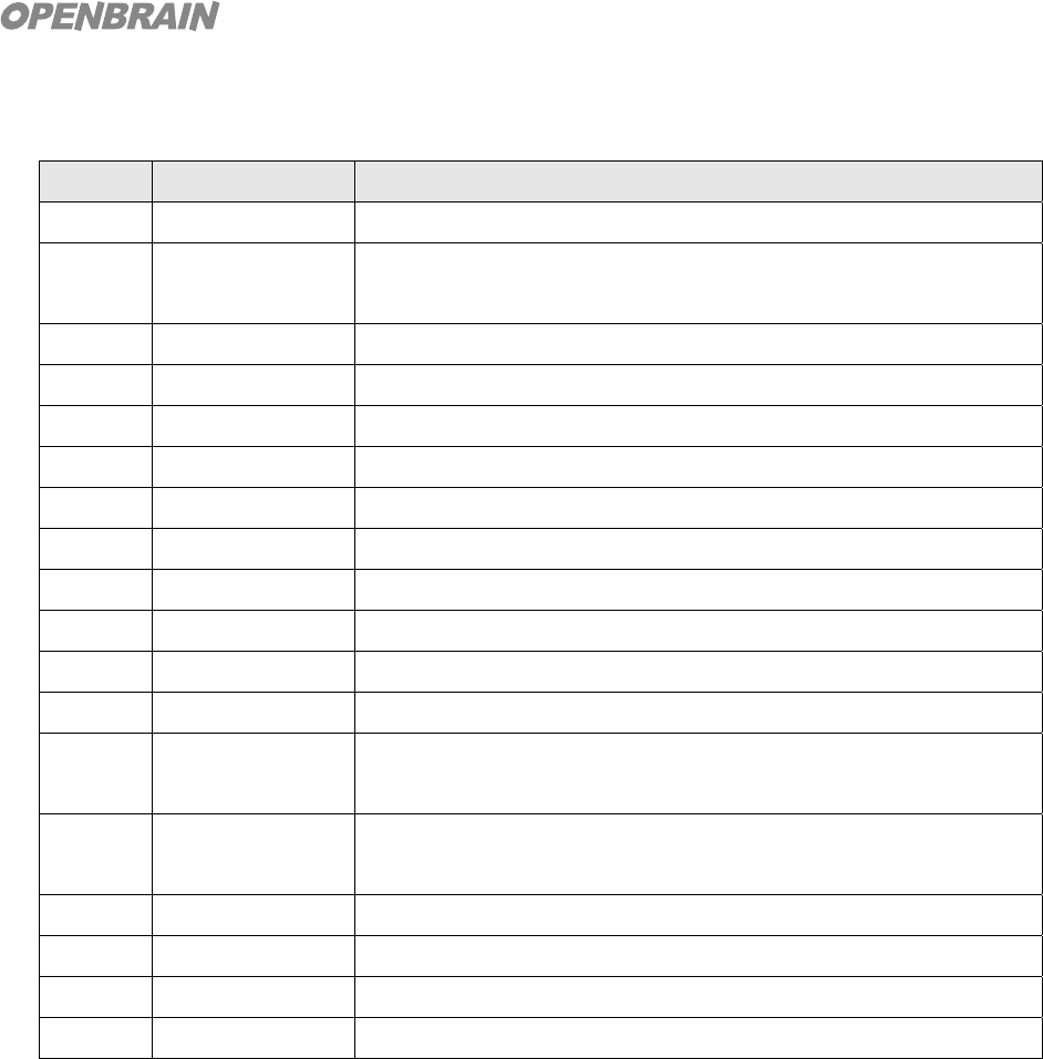
Pin Description
Pin No Name Description
1 VDD Positive supply (3.0V~4.2V)
2 RESETB Reset if low. Input debounced so must be low for > 5ms to cause a
reset
3 GND Ground
4 GND Ground
5 UART_TX UART data output
6 UART_RX UART data input
7 PCM_OUT PCM Synchronous data out
8 PCM_SYNC PCM Synchronous data sync
9 PCM_IN PCM Synchronous data in
10 PCM_CLK PCM Synchronous data clock
11 MIC+ Microphone differential, Input P
12 MIC- Microphone differential, Input N
13 SPK+ Speaker differential output P
or single ended output
14 SPK- Speaker differential output N
or single ended output
15 SPI_MISO Serial Peripheral interface data output
16 SPI_CSB Chip select for synchronous serial peripheral interface
17 SPI_MOSI Serial Peripheral interface data input
18 SPI_CLK Serial Peripheral interface clock
7
OPENBRAIN Technologies Co., LTD.
2. How to Use
2.1. Hardware Design Methodology
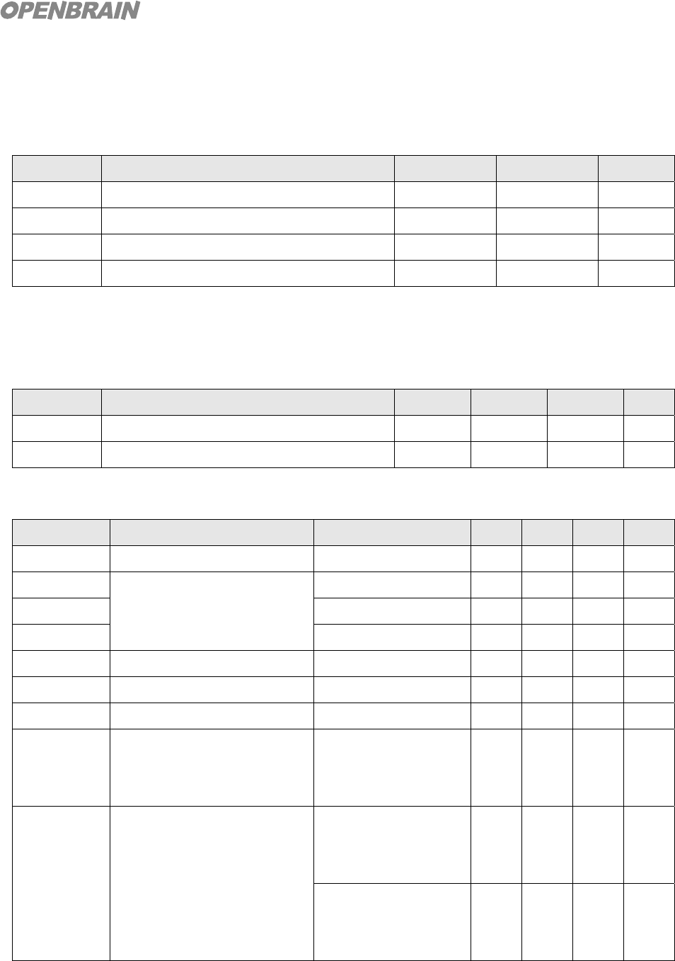
To use M5G module with existing communication devices, connect Host Processor with RESETB
and UART transceiver port as shown and connect SP+, SP-, MIC+ and MIC- to analog audio input/output
port of Audio Codec via Differential Mode. To connect audio input/output as Single Ended Mode, use any
one of the two terminals or use dedicated audio Amp to change the mode. But Differential Mode is
strongly recommended as it has the effect of improving S/N ratio. In case Single Ended Mode has to be
used, it is recommended that dedicated Amp be used.
2.2. Operating Procedures
The operating procedures for M5G module are as follows: Details on operating procedures and
UART communication protocol are defined in a separate document.
Pairing Mode: Searches for Bluetooth devices in the vicinity that support Handsfree and
Headset profiles and allows user to connect with a specific selected device.
Paging Mode: Connection attempt with paired device. If pairing information of multiple devices
are present, paging will start with the latest device that has been connected.
Connected Mode: Bluetooth link established with paged device.
Incoming Call: The state wherein bell rings when call is coming in.
Outgoing Call: The state wherein user makes a call.
Talk Mode: The state where user is talking with other party.
M5G Bluetooth
Audio Module
+3.3V
VDD
GND
RESETB
1
13,14
2
3,4
Host Processo
r
SP
11,12
MIC
A
udio Codec &
Amplifier
UART
5,6
8
OPENBRAIN Technologies Co., LTD.
3. Product Specifications
3.1. Electrical Specifications
Absolute Maximum Ratings
Symbol Parameter Min Max Unit
VDD Power Input Voltage (Pin 1) -0.4 +5.6 V
V+, V- Port Input Voltage VSS-0.4 VDD+0.4 V
PinRF RF Input Power 0 dBm
Ts Storage Temp. -35 +120 ℃
Be careful not to expose the product to voltages and signals beyond rated values indicated
above as this may cause damage.
Recommended Operating Conditions
Symbol Parameter Min Typ Max Unit
VDD Power Input Voltage (Pin 1) 2.2 3.3 4.2 V
To Operating Temp. -25 +25 +85 ℃
RF Characteristics
Symbol Parameter Condition Min Typ Max Unit
PoutRF Transmit Output Power 0 +2 +4 dBm
MODF1avg Modulation Characteristics Data = 00001111 140 164 175 kHz
MOFF2max Data = 10101010 115 150 kHz
F2avg/F1avg 0.8 0.97
20dB BW 940 1000 kHz
RXsense Receive Sensitivity BER < 0.001 -83 -79 dBm
PinRF Maximum Input Level -20 -10 dBm
IMP Inter-Modulation Performance F1 = +3MHz
F2 = +6MHz
PinRF = -64dBm
-39 -15 dBm
OOB Out Of Band Blocking
Performance
PinRF = -10dBm
30MHz ~ 2GHz
3GHz ~ 12.75GHz
-10 0 dBm
PinRF = -27dBm
2000MHz ~ 2399MHz
2498MHz ~ 3000MHz
-27 -15 dBm
* Measured Temperature : +25℃, Measured Voltage : 3.3V
9
OPENBRAIN Technologies Co., LTD.
Audio Characteristics
Symbol Parameter Min Typ Max Unit
Vain_max Input Full Scale at Maximum Gain 3 mVrms
Vain_min Input Full Scale at Minimum Gain 350 mVrms
BWain Bandwidth of Microphone Amplifier 20 kHz
IMPmic Mic Mode Input Impedance 20 kohm
IMPin Input Mode Input Impedance 130 ohm
Vsp_out Output Voltage Full Scale Swing(Differential) 2.0 Vp-p
Isp_out Output Current Drive (at Full Scale Swing) 10 20 40 mA
BWaout Output -3dB Bandwidth 18.5 kHz
Lres Allowed Load: Resistive 8 Open ohm
Lcap Allowed Load: Capacitive 500 pF
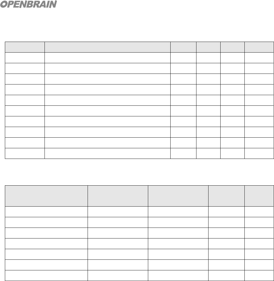
3.2. Current Consumption
Operating Mode Connection Type UART Rate(kbps)
Average
Unit
Page Scan - 115.2 0.49 mA
Inquiry and Page Scan - 115.2 0.83 mA
ACL 1.28s sniff Master 38.4 0.37 mA
SCO HV1 Master/Slave 38.4 41 mA
SCO HV3 Master/Slave 38.4 21~26 mA
Standby Host Connection - 38.4 76 uA
Reset(RESETB low) - - 58 uA
* Operating Temp: +25℃, Measurement point: 1.8V VDD input terminal
10
OPENBRAIN Technologies Co., LTD.
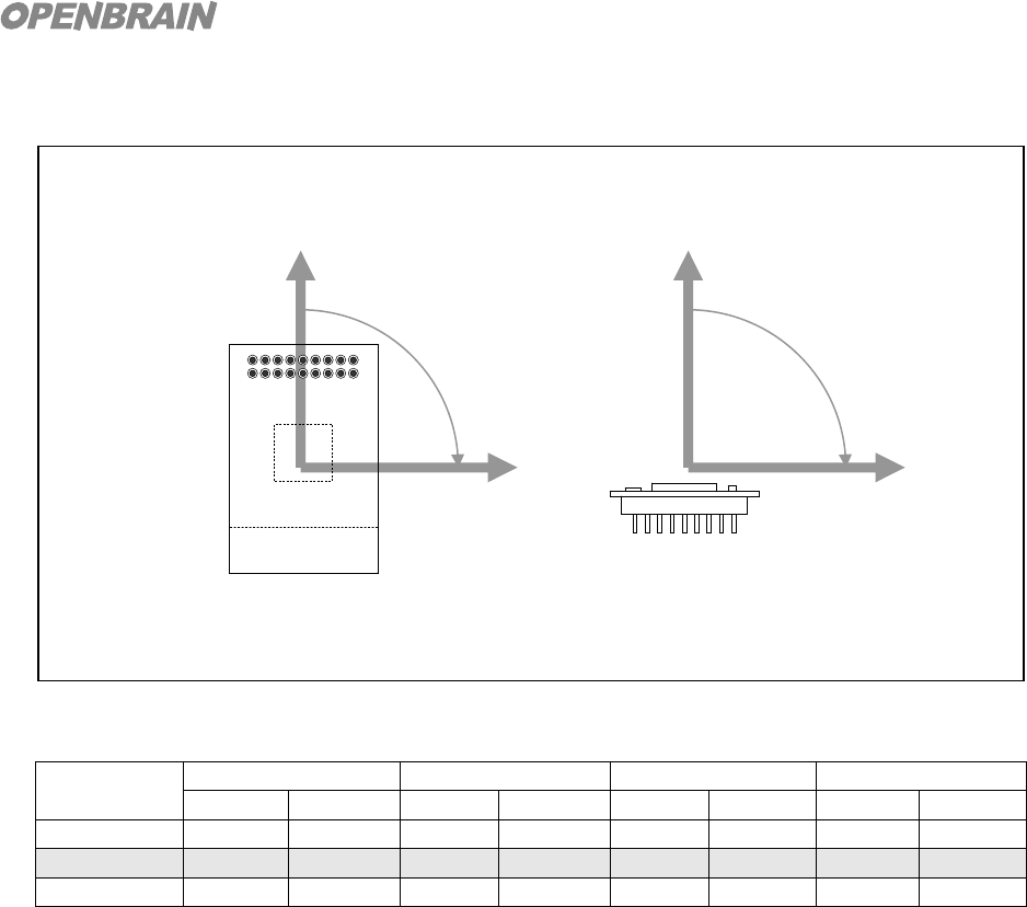
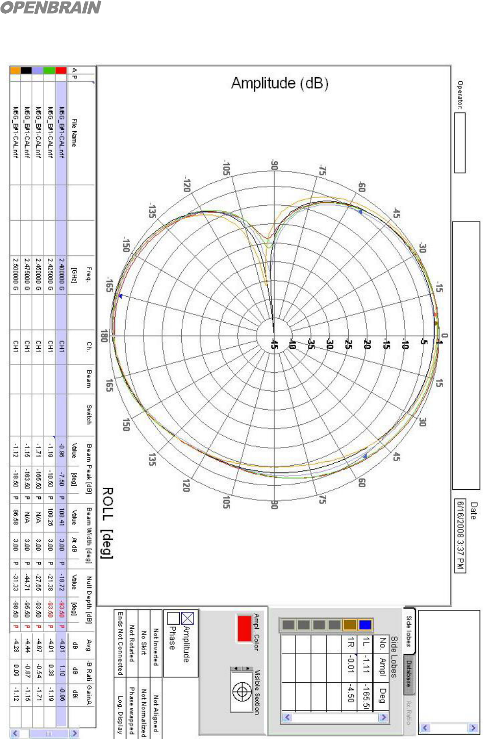
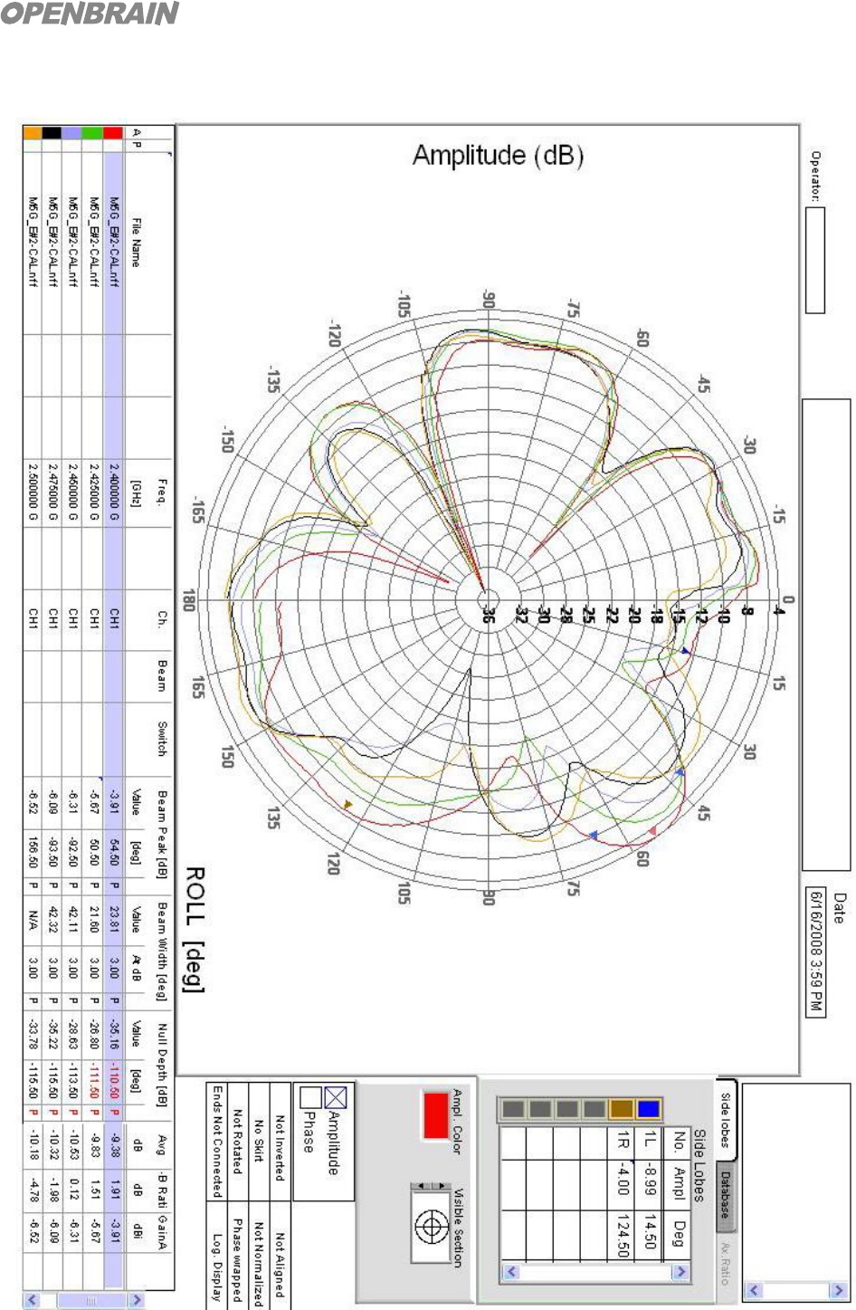
3.3. Antennae Radiation Characteristics
Radiation gain(E-Field, dBi)
Freq
(GHz)
XY XZ YZ Total Gain
Peak Average Peak Average Peak Average Peak Average
2.400 -0.96 -4.01 -1.11 -4.54 -6.31 -10.45 -0.96 -5.67
2.450 -1.71 -4.67 -1.53 -5.12 -7.27 -11.21 -1.53 -5.23
2.500 -1.12 -4.28 -1.18 -4.55 -7.64 -11.72 -1.12 -5.62
Y
θ
X
Y
φ
Z
Antennae Radiation Coordinates
11
OPENBRAIN Technologies Co., LTD.
Radiation Pattern - Azimuth XY (E-Field, Standalone Module)
12
OPENBRAIN Technologies Co., LTD.
Radiation Pattern - Azimuth XY (E-Field, Module Mounted onto Product)
13
OPENBRAIN Technologies Co., LTD.
3.4. Mechanical Specifications
Mechanical Dimension (Unit: mm)
36.0 ± 0.3
22.0 ± 0.3
2 4 6 . . 18
1 3 5 . . 17
Connecto
r
Bluetooth Chip
Antenna
2.0
1. VDD
2. RESETB
3. GND
4. GND
5. UART_TX
6. UART_RX
7. PCM_OUT
8. PCM_SYNC
9. PCM_IN
10. PCM_CLK
11. MIC+
12. MIC-
13. SPK+
14. SPK-
15. SPI_MISO
16. SPI_CSB
17. SPI_MOSI
18. SPI_CLK
3.0
7.5
2.0
3.0
1.2
2.0
4.0
1.4
14
OPENBRAIN Technologies Co., LTD.
4. Precautions during handling
4.1. General precautions
Precautions for handling M5G modules are as follows:
Do not expose the modules to static electricity as it may cause damage.
Use power source that will provide enough current to power input terminal of module.
Use only rated voltage or RF signals.
4.2. Maximizing RF Performance
To maximize RF performance of products that use M5G module, PCB has to be designed taking
into the consideration the following:
Sufficient Ground area has to be secured on Main PCB for stable RF performance.
Objects (conductors, insulators) close to antennae will interfere radiation and distort radiation
pattern. For conductors, they should be at least 10mm away from antennae and for insulators
such as plastic parts, at least 5mm away.
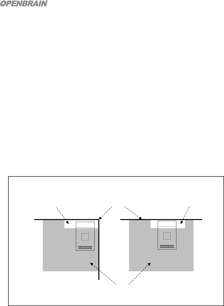
Main PCB must be designed such that the ground of Main PCB does not intrude into ground
of module and antennae boundary lines as shown in the diagram below.
How to mount module onto Main PCB
Ground surface of Main PCB
Boundary of Main PCB Remove Ground of PCB
Remove Ground of PCB
15
OPENBRAIN Technologies Co., LTD.
5. Reliability Test Result
5.1. Operating and storage temperature test results
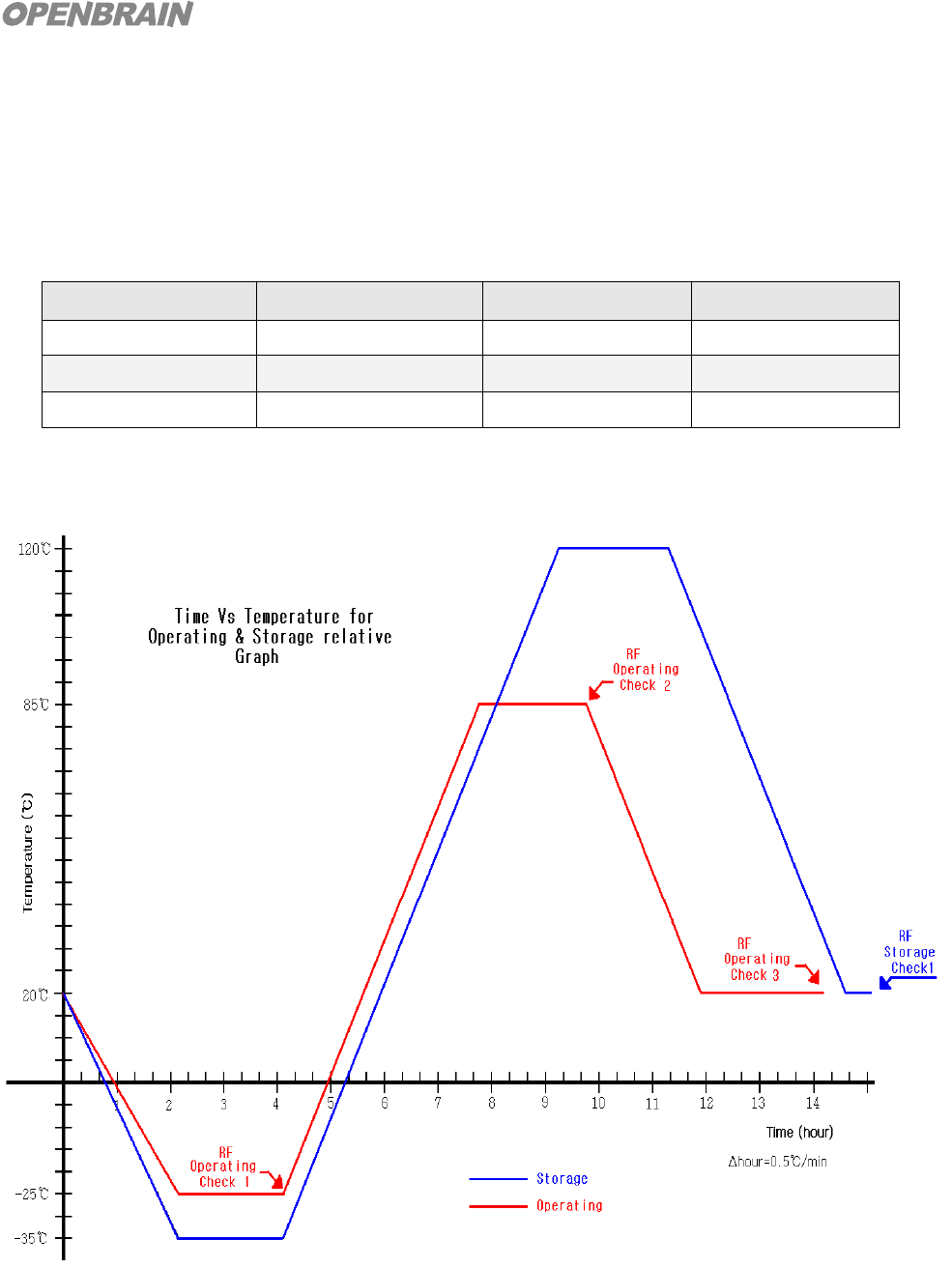
M5G module stored in temperature and moisture resistant chamber for 2 hours from -35 ~
+120℃
Operating Temp. Result Storage Temp. Result
+85℃ Normal +120℃ Normal
+20℃ Normal Normal
-25℃ Normal -35℃ Normal
5.2. Time Vs Temperature for Operating & Storage Relative Graph

16
OPENBRAIN Technologies Co., LTD.
5.3. Radio Characteristics for Each Check Point
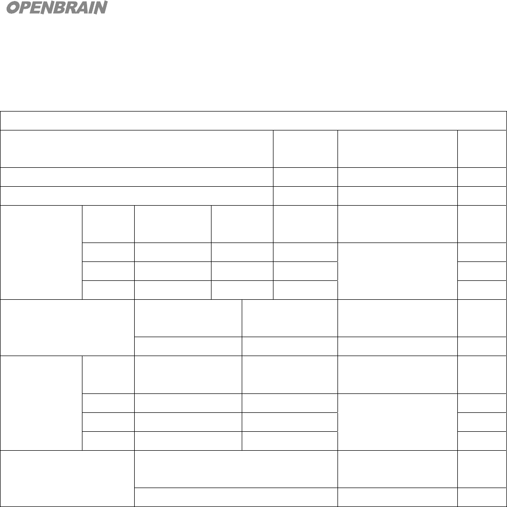
Measurement results and Bluetooth specification compliance of modules stored in
temperature and moisture resistant chamber for 2 hours at -25℃
RF Operating Check 1(-25℃)
Result
(dBm)
Bluetooth
Spec.(dBm)
Verdict
Output Power +2.65 -6 to +4 Pass
Sensitivity at 0.1% BER for all packet types -86 ≤-70 Pass
Modulation
Characteristic
s
Channel df1_avg
(kHz)
df2_avg
(kHz)
df2/df1
(%)
Bluetooth
Spec.
Verdict
0 164.6 158.7 96.42 140<df1_avg, df2_avg
<175
0.80<df2/df1(%)
Pass
39 164.5 155.7 94.65 Pass
78 164.7 156.1 94.78 Pass
Initial Carrier Frequency
Tolerance
(ICFT)
Df0_max
(kHz)
Df0_min
(kHz)
Bluetooth
Spec.(kHz)
Verdict
0.2 -0.1 ±75 Pass
Carrier
Frequency
Drift(CFD)
Channel f_drift_max
(kHz)
Drift_rate_max
(kHz/50us)
Bluetooth
Spec.(kHz)
Verdict
0 10.1 4.7 Drift Rate Max
≤20
f drift max≤40
Pass
39 9.4 -5.3 Pass
78 7.4 6.1 Pass
TX Output Spectrum
-20dB Bandwidth
f_h-f_l
Bluetooth
Spec.(MHz)
Verdict
0.914 f_h - f_l <= 1.000MHz Pass
17
OPENBRAIN Technologies Co., LTD.
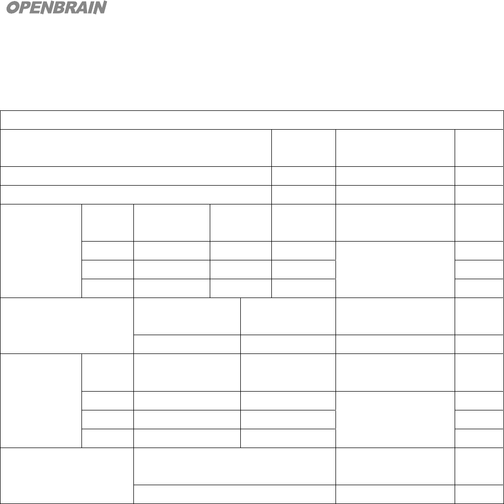
Measurement results and Bluetooth specification compliance of modules stored in
temperature and moisture resistant chamber for 2 hours at 85 )℃
RF Operating Check 2 (85℃)
Result
(dBm)
Bluetooth
Spec.(dBm)
Verdict
Output Power +3.8 -6 to +4 Pass
Sensitivity at 0.1% BER for all packet types -82.5 ≤-70 Pass
Modulation
Characteristic
s
Channel df1_avg
(kHz)
df2_avg
(kHz)
df2/df1
(%)
Bluetooth
Spec.
Verdict
0 163.8 156.5 95.54 140<df1_avg, df2_avg
<175
0.80<df2/df1(%)
Pass
39 164.9 157.6 96.16 Pass
78 164.9 156.5 95.49 Pass
Initial Carrier Frequency
Tolerance
(ICFT)
Df0_max
(kHz)
Df0_min
(kHz)
Bluetooth
Spec.(kHz)
Verdict
29.8 29.3 ±75 Pass
Carrier
Frequency
Drift(CFD)
Channel f_drift_max
(kHz)
Drift_rate_max
(kHz/50us)
Bluetooth
Spec.(kHz)
Verdict
0 -13.6 6.4 Drift Rate Max
≤20
f drift max≤40
Pass
39 -10.2 -5.7 Pass
78 -15.9 -8.1 Pass
TX Output Spectrum
-20dB Bandwidth
f_h-f_l
Bluetooth
Spec.(MHz)
Verdict
0.914 f_h - f_l <= 1.000MHz Pass
18
OPENBRAIN Technologies Co., LTD.
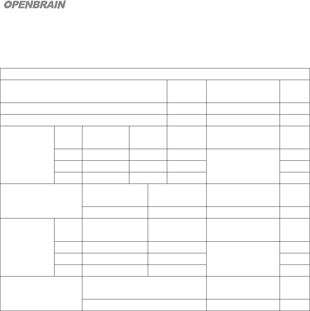
Measurement results and Bluetooth specification compliance of modules stored in
temperature and moisture resistant chamber for 2 hours at 20 )℃
RF Operating Check 3 (20℃)
Result
(dBm)
Bluetooth
Spec.(dBm)
Verdict
Output Power +2.54 -6 to +4 Pass
Sensitivity at 0.1% BER for all packet types -84.5 ≤-70 Pass
Modulation
Characteristic
s
Channel df1_avg
(kHz)
df2_avg
(kHz)
df2/df1
(%)
Bluetooth
Spec.
Verdict
0 164.3 160.1 97.44 140<df1_avg, df2_avg
<175
0.80<df2/df1(%)
Pass
39 164.6 159.9 97.14 Pass
78 164.7 159.4 96.78 Pass
Initial Carrier Frequency
Tolerance
(ICFT)
Df0_max
(kHz)
Df0_min
(kHz)
Bluetooth
Spec.(kHz)
Verdict
13.3 11.5 ±75 Pass
Carrier
Frequency
Drift(CFD)
Channel f_drift_max
(kHz)
Drift_rate_max
(kHz/50us)
Bluetooth
Spec.(kHz)
Verdict
0 8.4 -5.4 Drift Rate Max
≤20
f drift max≤40
Pass
39 6.9 -6.4 Pass
78 7.0 6.5 Pass
TX Output Spectrum
-20dB Bandwidth
f_h-f_l
Bluetooth
Spec.(MHz)
Verdict
0.914 f_h - f_l <= 1.000MHz Pass
19
OPENBRAIN Technologies Co., LTD.
Measurement results and Bluetooth specification compliance of modules stored in
temperature and moisture resistant chamber for 2 hours at -35 ,℃ 120℃(Storage Graph)
RF Storaged Check 1 (-35℃ ~ +120℃)
Result
(dBm)
Bluetooth
Spec.(dBm)
Verdict
Output Power 0.1 -6 to +4 Pass
Sensitivity at 0.1% BER for all packet types -81 ≤-70 Pass
Modulation
Characteristics
Chann
el
df1_avg
(kHz)
df2_avg
(kHz)
df2/df1
(%)
Bluetooth
Spec.
Verdict
0 164.6 160.3 97.45 140<df1_avg, df2_avg
<175
0.80<df2/df1(%)
Pass
39 164.6 160.2 97.33 Pass
78 164.5 159.3 96.84 Pass
Initial Carrier Frequency
Tolerance
(ICFT)
Df0_max
(kHz)
Df0_min
(kHz)
Bluetooth
Spec.(kHz)
Verdict
13.2 11.9 ±75 Pass
Carrier
Frequency
Drift(CFD)
Chann
el
f_drift_max
(kHz)
Drift_rate_max
(kHz/50us)
Bluetooth
Spec.(kHz)
Verdict
0 8.3 7.1 Drift Rate Max
≤20
f drift max≤40
Pass
39 8.4 7.2 Pass
78 6.4 7.2 Pass
TX Output Spectrum
-20dB Bandwidth
f_h-f_l
Bluetooth
Spec.(MHz)
Verdict
0.922 f_h - f_l <= 1.000MHz Pass
20
OPENBRAIN Technologies Co., LTD.
6. Packaging
Packaging
(
unit: mm
)
247
312
15
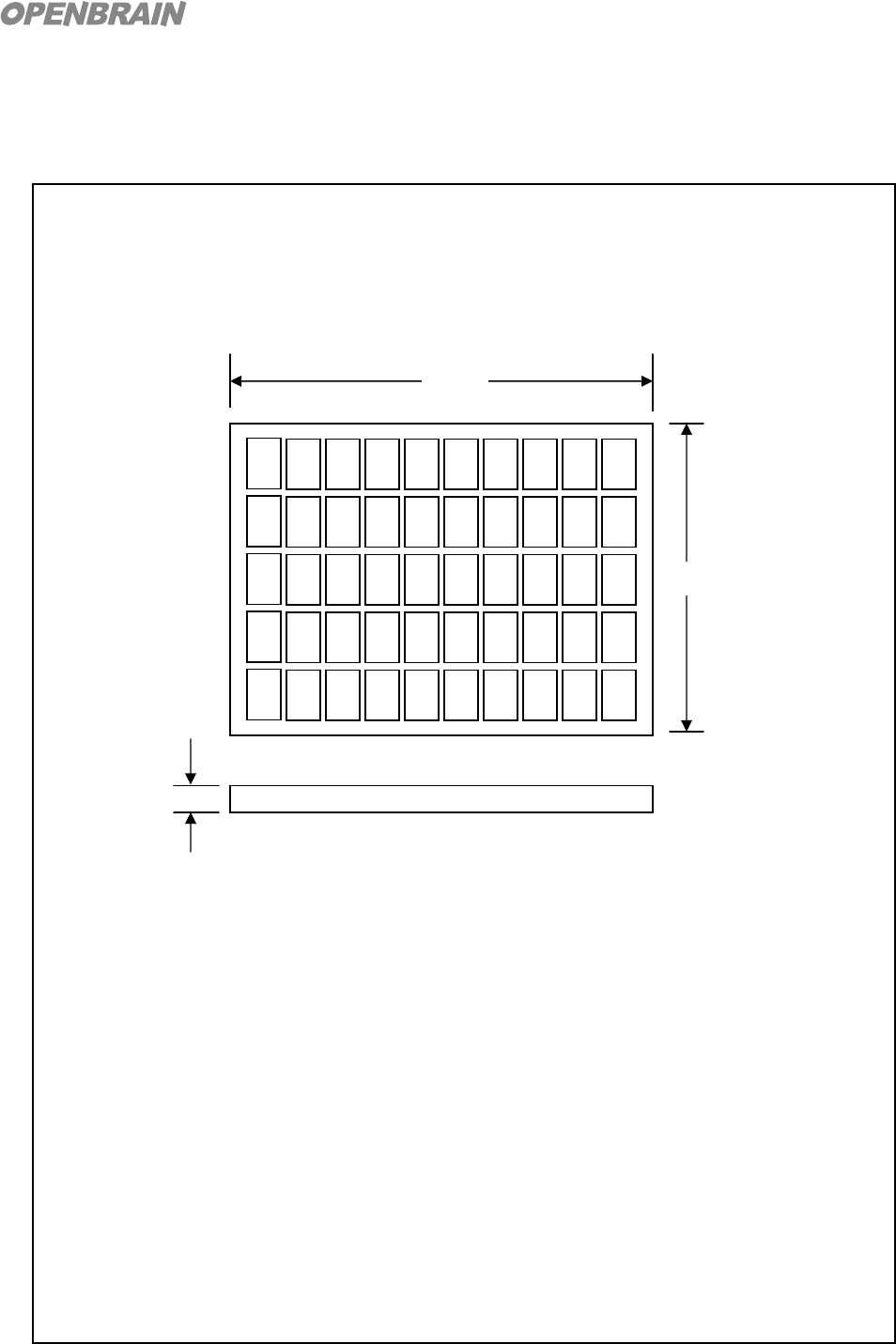
* Individually packed in soft white tray (50 pcs per tray)

21
OPENBRAIN Technologies Co., LTD.
7. Product Setting (Customization)
Configuration of Bluetooth Parameters - Factory Setting
No Parameter Value
1 Local Device Name “VPAD” (ASCII)
2 Bluetooth Device Address “00150EE20000 ~ 00150EF00000” (HEX)
3 UART Baud Rate 115,200 bps
4 UART Parity None
5 UART Stop Bit 1
6 UART Flow Control None
7 Class Of Device Audio/Phone/Audio_Gateway (0x20 0x02 0x10)
8 Security Mode Level 1 (depends on remote device security level)
9 Operating Mode Active and Sniff Mode Support.
10 Page Scan Mode Discoverable & Connectable
11 Inquiry Mode Non-discoverable & Non-connectable
Caution
Modifications not expressly approved by the party responsible for compliance could void the
user’s authority to operate the equipment.
Assure compliance
The use of the modular transmitter is only approved to be used inside SBN Tech
equipment. We assure the compliance of the end product when it is assembled
inside SBN Tech equipment.

22
OPENBRAIN Technologies Co., LTD.
8. FCC Information to User
This equipment has been tested and found to comply with the limits for a Class B digital device,
pursuant to Part 15 of the FCC Rules. These limits are designed to provide reasonable protection
against harmful interference in a residential installation. This equipment generates, uses and can
radiate radio frequency energy and, if not installed and used in accordance with the instructions, may
cause harmful interference to radio communications. However, there is no guarantee that interference
will not occur in a particular installation. If this equipment does cause harmful interference to radio or
television reception, which can be determined by turning the equipment off and on, the user is
encouraged to try to correct the interference by one of the following measures:
• Reorient or relocate the receiving antenna.
• Increase the separation between the equipment and receiver.
• Connect the equipment into an outlet on a circuit different from that to which the receiver is
con-nected.
• Consult the dealer or an experienced radio/TV technician for help.
FCC Compliance Information : This device complies with Part 15 of the FCC Rules. Operation is
subject to the following two conditions: (1) This device may not cause harmful interference, and (2)
this device must accept any interference received, including interference that may cause undesired
operation
IMPORTANT NOTE:
FCC RF Radiation Exposure Statement:
This equipment complies with FCC RF radiation exposure limits set forth for an uncontrolled
environment. This equipment should be installed and operated with a minimum distance of 20
centimeters between the radiator and your body.This transmitter must not be co-located or operating
in conjunction with any other antenna or transmitter.