OPISYS orporated AVHR-5000 Dual Band Repeater (Model: AVHR-5000) User Manual Microsoft PowerPoint manual
OPISYS Incorporated Dual Band Repeater (Model: AVHR-5000) Microsoft PowerPoint manual
Users Manual
Installation User Guide
MODEL : AVHR
MODEL : AVHR-
-5000
5000

Page 1
- Content -
1. General Information
1.1 Precautions
1.2 Features
2. System Components
3. Installation
3.1 Outside Antenna Installation
3.2 Inside Antenna Installation
3.3 Amplifier and Antenna Connection
3.4 Operating Instructions
4. Trouble Shooting
4.1 LED Alarm
4.2 Insufficient Outside Signal Problem
4.3 Vehicle Battery Discharge Problem
5. Specification
5.1 Amplifier Specification
5.2 Outside Antenna Specification
5.3 Inside Antenna Specification
5.4 Cigarette Power Code Specification
6. Certificates
7. Memo
1. General Information
1.1 Precautions
1.1.1 Do not drop the device
- Drop could damage the product
1.1.2 Do not place near magnetic
- It could be cause of malfunction
1.1.3 Product is supposed to be used with the cigarette power code. If you
want to use fuse cable, please ask professional installers.
1.1.4 Please unplug either with cigarette power code or fuse cable if you
don’t use
- It may cause battery discharge
1.1.5 Set up product on advised location
- It may not properly operate on unadvised location
1.1.6 Do not repair or remodel
- It could be cause of malfunction. Please contact a store where
you purchased if there is a problem
1.1.7. Do not operate device while driving
- It could be cause of traffic accident
1.1.8 Turn off the ignition before set up the device.
1.1.9 Do not put the device near vehicle air bag in the car
- You could be hurt by burst air bag or air bag which doesn’t
operate properly
1.1.10 Do not handle with wet hands
- Avoid risk of an electric shock
1.1.11 Clean up the surface where you set up inside and outside antenna
- It could be cause of a traffic accident when the antennas
detached from the surface.
1.1.12 Please stop use and unplug when smog comes out of the product
or could detect strange odor
Page 2
Reference : Things you need to know to operate the product
properly
Caution : Things that you need to know not to damage the
product
Warning : Showing instructions for users to avoid unexpected
hazard
1.2 Features
1.2.1 Summary
This product is installed on cars, trucks, trailers, boats and homes to
improve user’s mobile phone signal.
It is a RF type amplifier used for only CDMA Cellular bands
in the 800MHz and PCS1900MHz .
(Please see page 11 for Operating Frequency)
1.2.2 Features
Page 3
I. Decrease dropped call
II. Increase 2G/3G/4G data speed
III. Battery life extension
IV. Voice quality improvement
I. Strong coverage area
- Gain 55dB
II. Automatic Overload Protect & Detect System
- Plug and play systems
III. IS-95A Spurious Specifications with 25dBm(0.3W) Output power
- Providing high data communication rate
IV. Complete Repeater Kit.
-Providing all components for installation
V. Dual Band Amplifier
- 800MHz / 1900MHz
VI. LED Alarm System
VII. GUI(Graphic User Interface)
- Please ask professional installers about GUI program.
VIII. Cost Effective Application for Vehicles, Boats, and Homes
- For at home users need to purchase cables, inside and outside
antennas to install.
Page 4
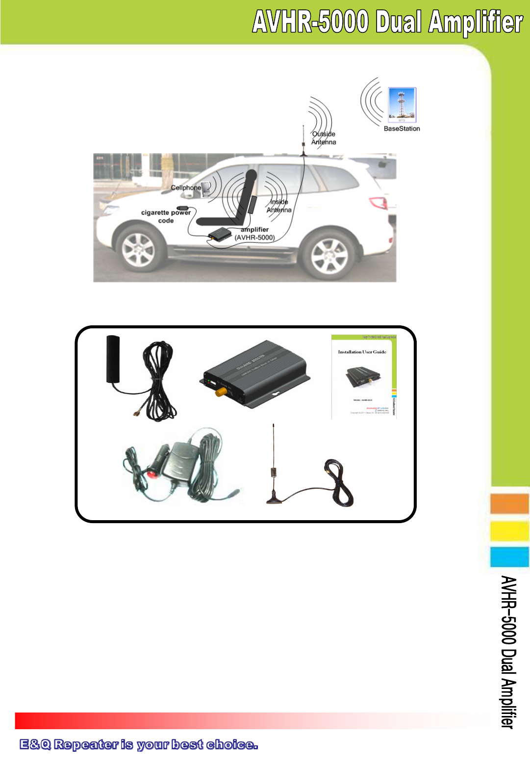
① Inside Antenna ②AVHR-5000 ③User Manual
④cigarette power code ⑤Outsider Antenna
① . Inside Antenna: connects signal between mobile phone and amplifier
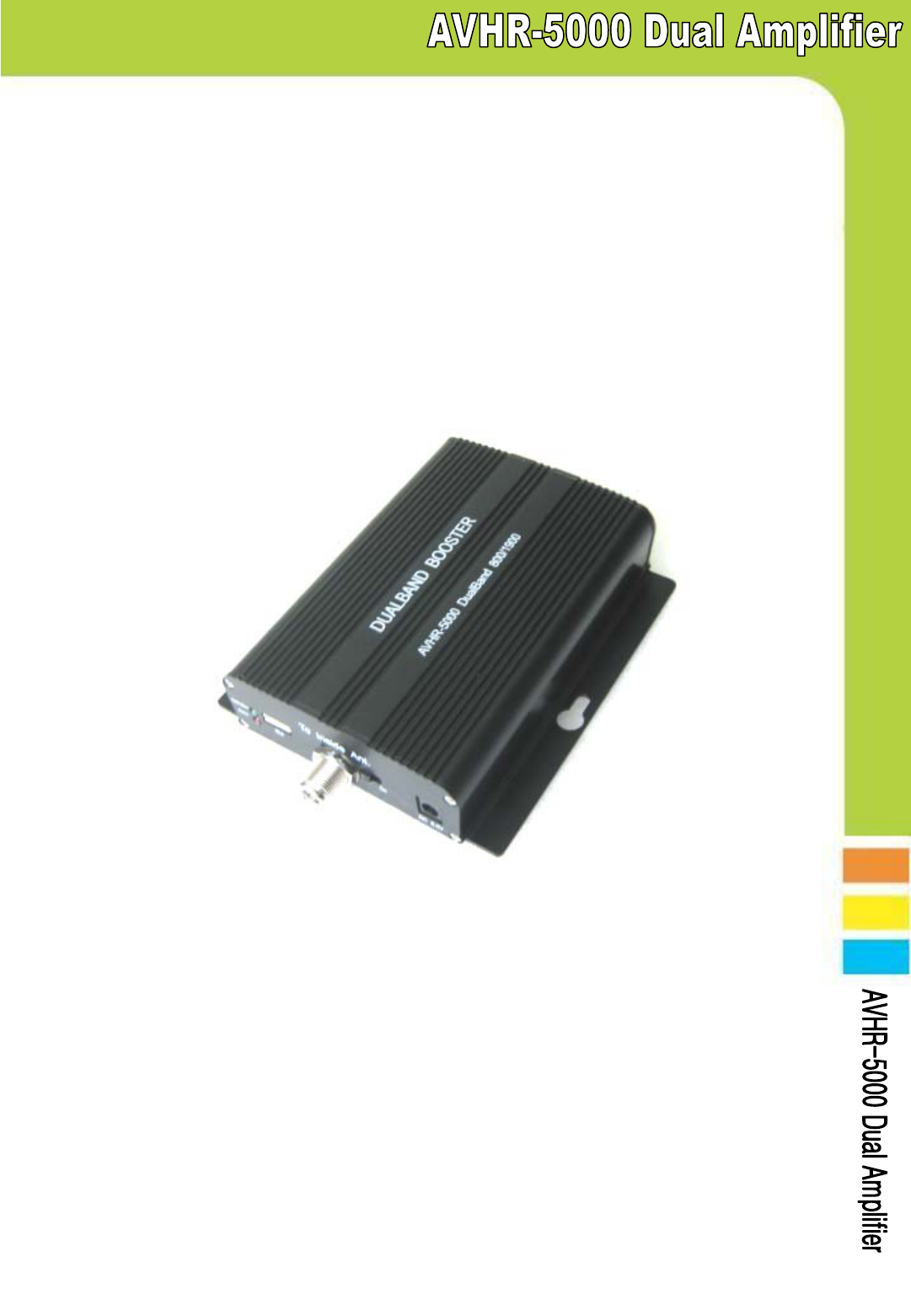
②. AVHR-5000: amplifies signal from outside antenna which receives
signal from a base station and sends amplified signal to mobile phone
③. User Manual: shows how to operate system
④. Cigarette Power Code : is the source of electricity
⑤. Outside Antenna: connects signal between base station and amplifier
▣ System Components
1.2.3 Installation
2. System Components
Page 5
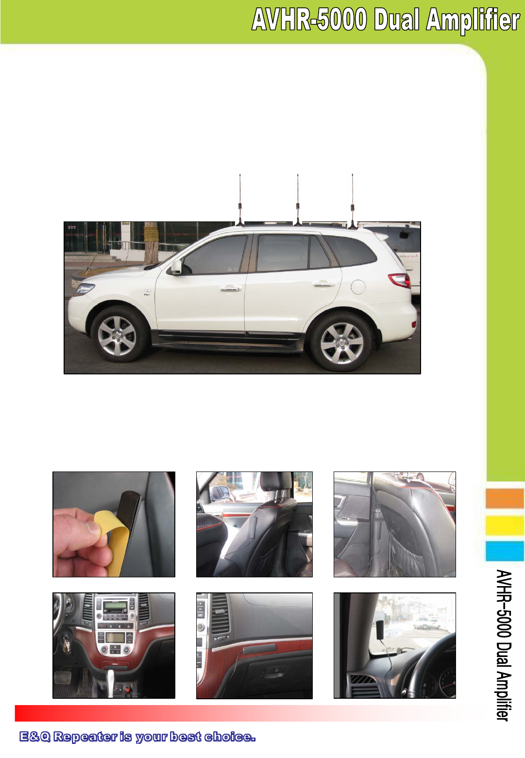
3. Installation
3.1 Outside Antenna Installation
3.1.1 Outside antenna is magnetic. So you can mount on the roof of vehicle
3.1.2 Outside antenna should be distance at least 5 feet from inside antenna
3.1.3 As showing on the picture below, suggested place to mount outside
antenna is rear end of roof
3.2 Inside Antenna Installation
3.2.1 Inside antenna is self adhesive. You can place it wherever you want
3.2.2 Before installation, please remove attached paper
3.2.2 Recommend to mount under location shown
on the picture
Better Best
Good
Page 6
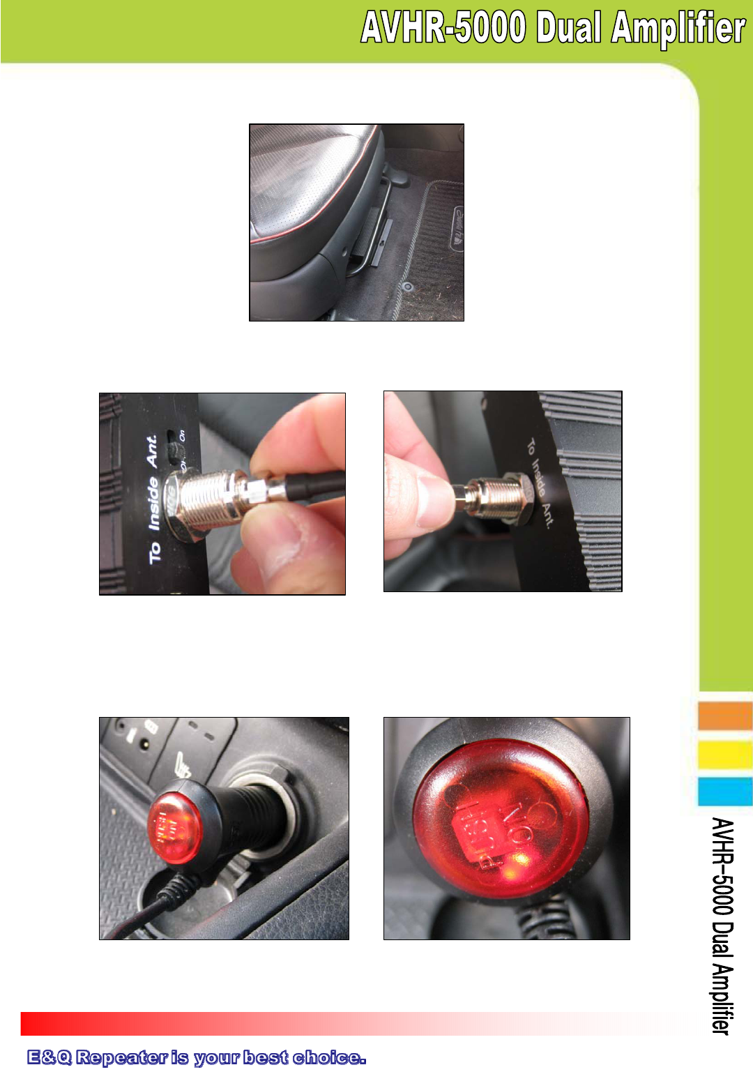
3.3 Amplifier and Antenna Connection
3.3.1 Place the amplifier under the seat or appropriate location.
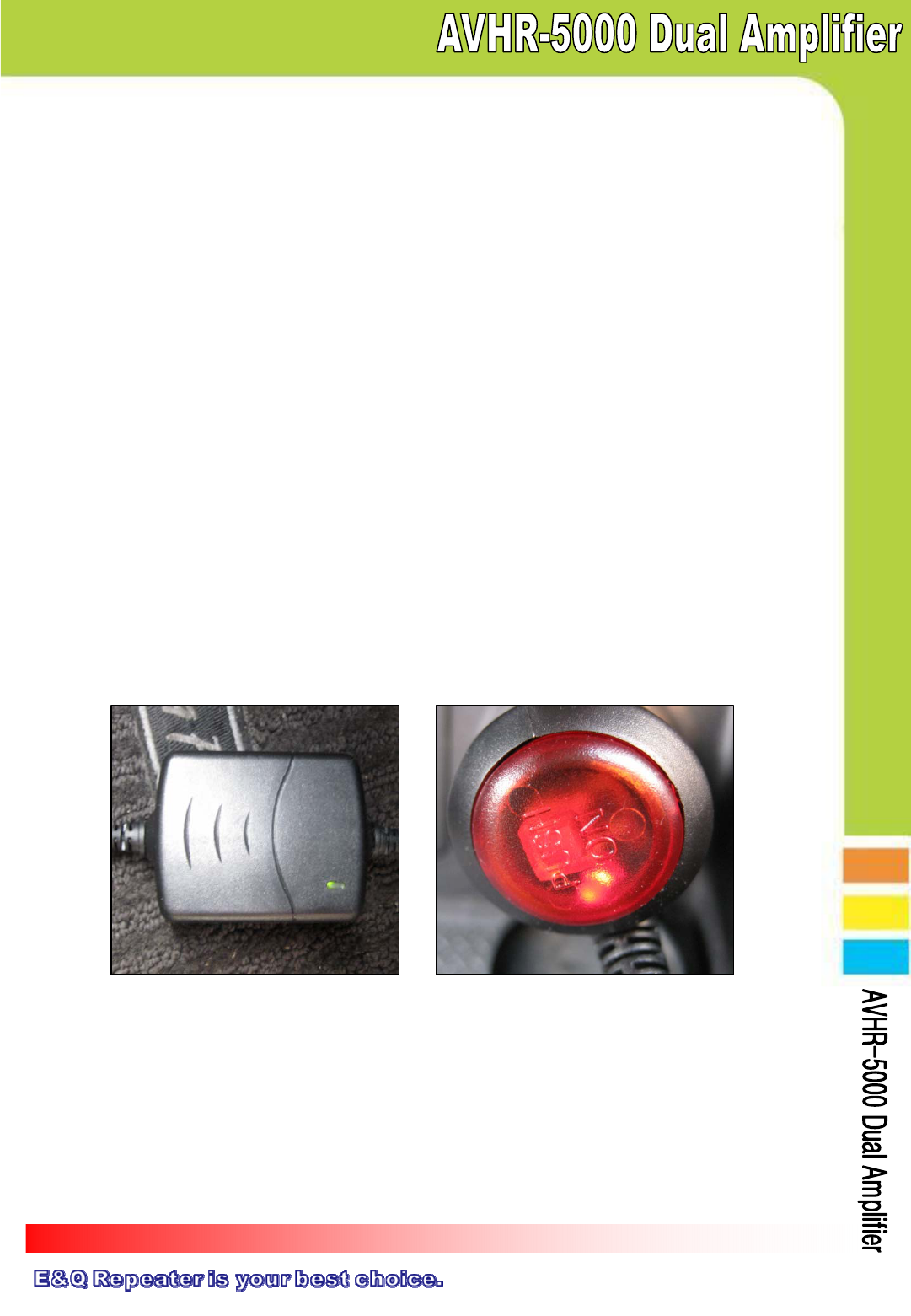
3.4 Operating Instructions
3.4.1 As the picture shown below, plug in the cigarette power code and press
red button to turn on
3.3.2 Connect inside antenna connector to repeater
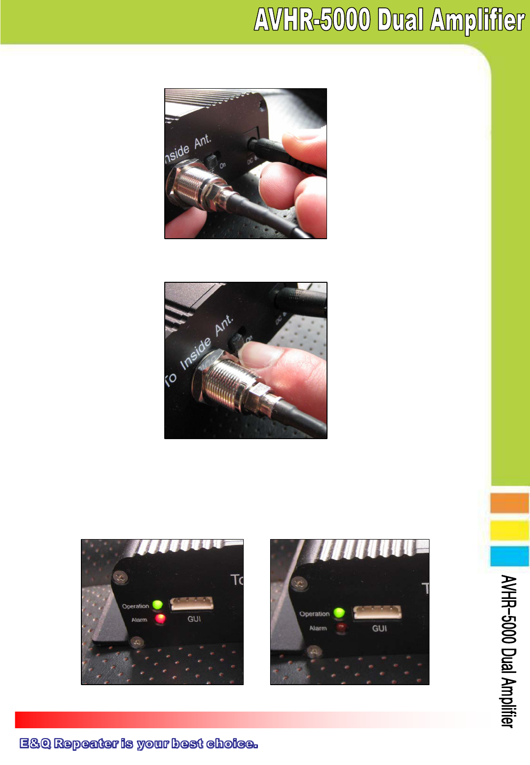
Page 7
3.4.2 Connect DC Jack as picture down below
3.4.3 Turn on the Switch as picture down below
3.4.4 After turning on switch, green LED light will be on(Green LED means that
system is normal mode)
※ Green and Red LED simultaneously brinks 3 times and then only
green LED light will be on
Page 8
4. Trouble Shooing
4.1 LED Alarm
Item GREEN LED RED LED 문제점 찾기
Setting/Resetting ON (after 3 times
blinks) 3 times blinks See 4.1.1
Normal Mode ON OFF See 4.1.2
Cellular
Overload Blink( once) -See 4.1.3
Oscillation Blink(twice) -See 4.1.4
Insufficient
Isolation Blink(3 times) -See 4.1.5
Alarm
Checking Blink(Consecutively) -See 4.1.6
PCS
Overload -Blink( once) See 4.1.3
Oscillation -Blink(twice) See 4.1.4
Insufficient
Isolation -Blink(3 times) See 4.1.5
Alarm
Checking -Blink(Consecutively) See 4.1.5
4.1.1 ① Check if the LED light is on, on the cigarette power code
② Verify that DC code is connected correctly
4.1.2 ① Green LED light is normal mode. If it is blinking 2-3 times in a few
seconds, please see 4.1.3 ~ 4.1.6
4.1.3 ① This is normal mode that checking on input power signal and shows
signal status to users.
③ It will go back to normal mode soon
4.1.4 ① There is an oscillation between inside and outside antenna.
② This status is caused by a structure around that temporarily
disturbs mobile signals. Please move your vehicle to other location.
LED light will turn to green
Page 9
4.2 Insufficient Outside Signal Problem
After repeater installed, if there is insufficient outside signal around your
vehicle such as uncovered signal area, you may not use your mobile phone
4.3 Vehicle Battery Discharge Problem
Verify cigarette power code LED light is on as shown below. If not, check
either vehicle key is appropriately positioned or engine is on. In case of
battery discharge, replace battery.
4.1.5 ① There is a insufficient isolation between inside and outside antenna
② While installing if LED light blinks three times, move the inside and
outside
antenna away and turn on/off and move antenna as needed.
③ If there was no blinking problem while set up but happens after, it
could be caused by surrounding structure but that could be come
back to normal if you move to different location.
4.1.6 ① Repeater CPU software is checking out if there are any
problems such as isolation, overload or conciliation.
② On alarm checking status repeater is not operating
Page 10
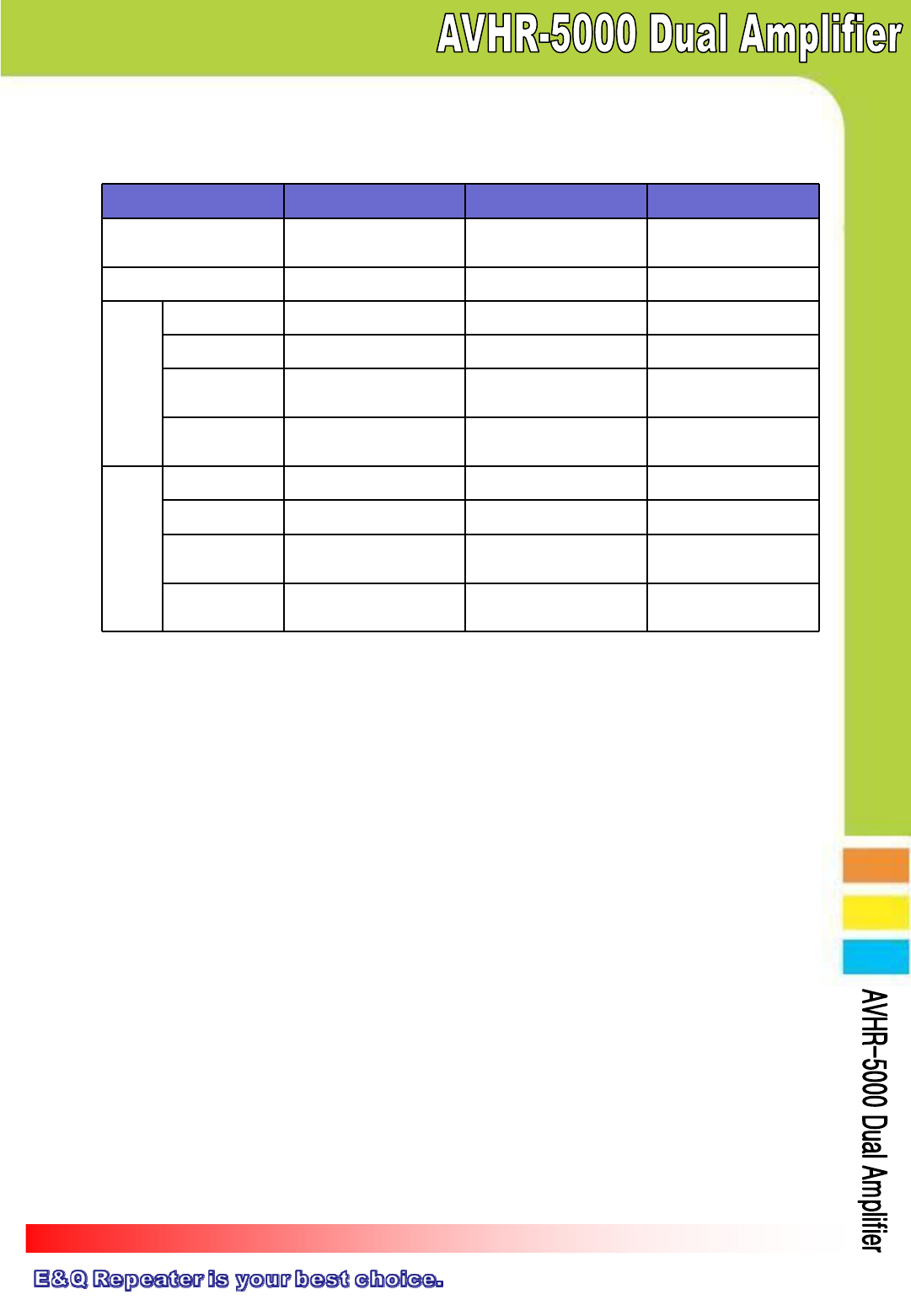
5. Specification
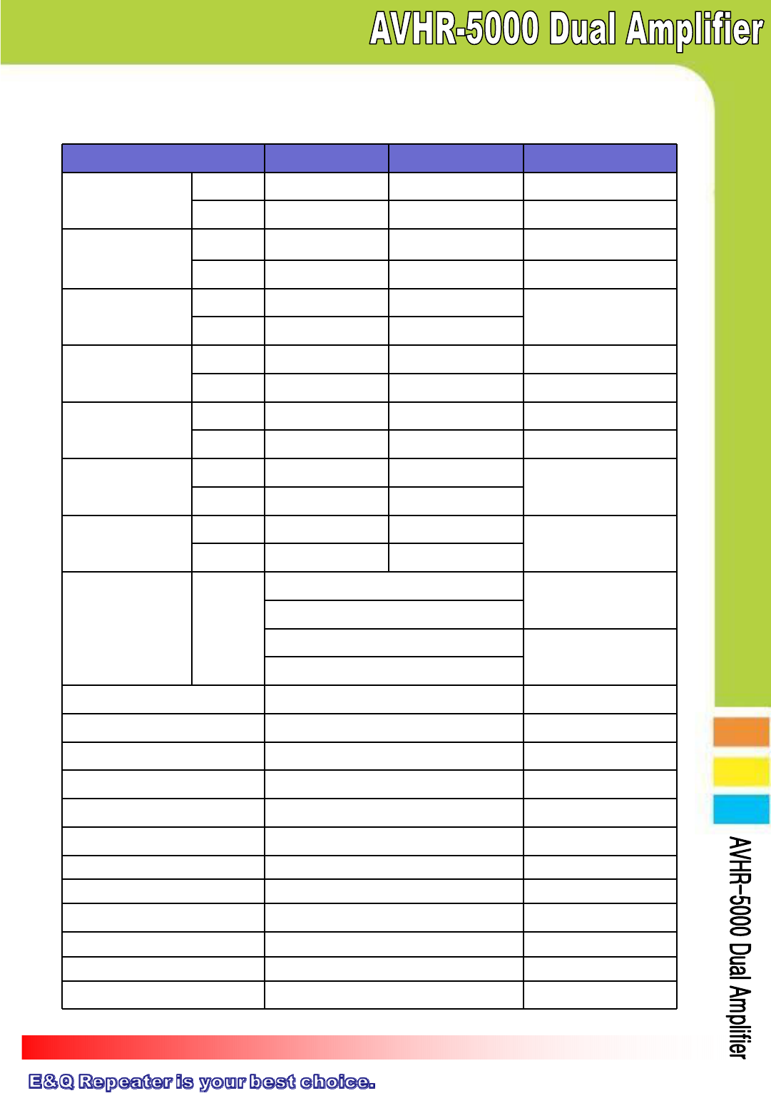
5.1 Amplifier Specification
Items Cellular PCS Remarks
Operating
Frequency
Downlink 869 ~ 894 MHz 1930 ~ 1990 MHz CDMA Only
Uplink 824 ~ 849 MHz 1850 ~ 1910 MHz CDMA Only
Gain
Downlink 55dB±2.0dB 55dB±2.0dB
Uplink 55dB±2.0dB 55dB±2.0dB
Output Power Level
Downlink +10dBm +10dBm
@ 1FA
Uplink +25dBm +25dBm
Ripple
Downlink < 5dB < 7dB
Uplink < 5dB < 7dB
Noise Figure
Downlink < 5dB < 5dB
Uplink < 5dB < 5dB
ALC Level
Downlink +10dBm ±1dB +10dBm ±1dB
@ 1FA
Uplink +25dBm ±1dB +25dBm ±1dB
Shutdown Level
Downlink +10dBm ±1dB +10dBm ±1dB
After ALC
Uplink +25dBm ±1dB +25dBm ±1dB
Spurious
Downlink
&
Uplink
-45dBc/30kHz @±885KHz
@PCS
-50dBc/30kHz @±1.98MHz
-45dBc/30kHz @±750KHz
@Cellular
-50dBc/30kHz @±1.98MHz
VSWR < 1 : 1.8
Propagation Delay < 1us
Frequency Stability ≤ ±0.05ppm
GUI Interface RS-232C
Isolation Detection Range 45dB ~ 65dB
Only Uplink Shutdown ≥ -45dBm ±1dB @ downlink Input Signal For BTS Protection
Input Voltage 6.0Vdc / 3.5A Cigar Charger ‘s Vdc
Power Consumption 6.0Vdc / 840mA @ No call
RF Connector Type FME-male
Operating Temperature -40°C ~ +50°C (-40°F ~ 122°F)
Weight < 2.2 Ibs (< 1.0kg)
Size(L*W*H) 4.9*4.8*1.4nch (125.5 * 123 * 35.5mm)
Page 11
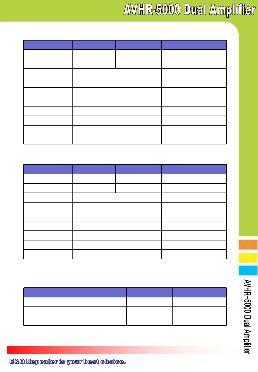
5.2 Outside Antenna Specification
5.3 Inside Antenna Specification
5.4 Cigarette Power Code Specification
5.4.1 Input Specification
Items Cellular PCS Remarks
Operating Frequency 820 ~ 890 MHz 1710 ~ 1990 MHz -
Bandwidth 70MHz 170MHz -
Gain 5dBi -
VSWR ≤ 2.0 : 1 -
Impedance 50 Ω -
Polarization Vertical -
Connector FME(Female) -
Antenna Length 28Cm -
Weight 220g -
Cable Length 5M -
Items Cellular PCS Remarks
Operating Frequency 820 ~ 890 MHz 1710 ~ 1990 MHz -
Bandwidth 70MHz 170MHz -
Gain 2dBi -
VSWR ≤ 2.0 : 1 -
Impedance 50 Ω -
Polarization Vertical or Horizontal -
Connector FME(Female) -
Weight 50g -
Cable Length 2M -
Items Min Typical Max
Normal DC Input Voltage 12V -24V
DC Input Voltage Range 12V -24V
DC Input Voltage Current - - 3.0A
Page 12
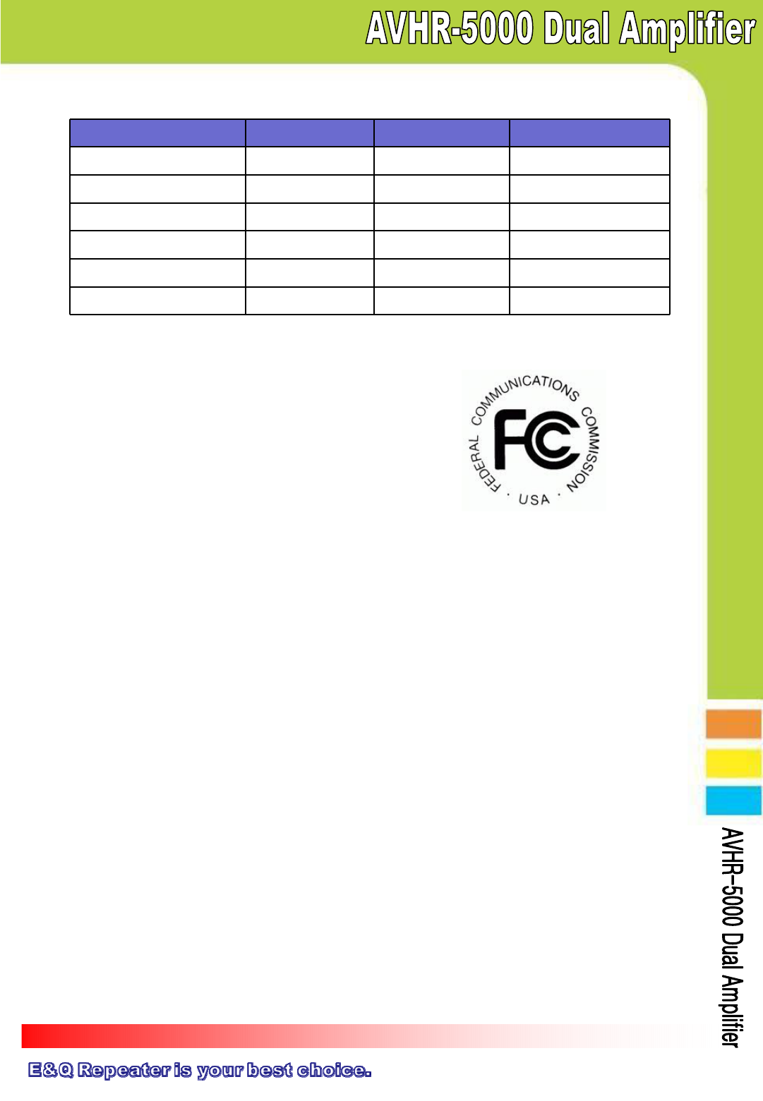
5.4.2 Output Specification
Items Min Typical Max
Normal DC Output Voltage -6.0Vdc -
DC Output Voltage Range 5.7Vdc -6.3Vdc
Load Current Range - - 3.5A
Ripple - - 350mV
Over Current Protection 4.2 -7.0A
Short Circuit Protection -Yes -
6. Certificates
6.1 FCC Certification
▪ Model : AVHR-5000
▪ Certificate Data : 2011.03
▪ Certificate No.:
6.2 IC Certification
▪ Model : AVHR-5000
▪ Certificate Data : 2011.03
▪ Certificate No.:
7. Requirement
A minimum separation distance of 8 inchs(20 cm)
must be maintained between the user/bystander and
the vehicle mounted external antenna to satisfy
FCC RF exposure requirements.
For more information about RF exposure, visit the FCC
website at www.fcc.gor
Page 13
7. Memo