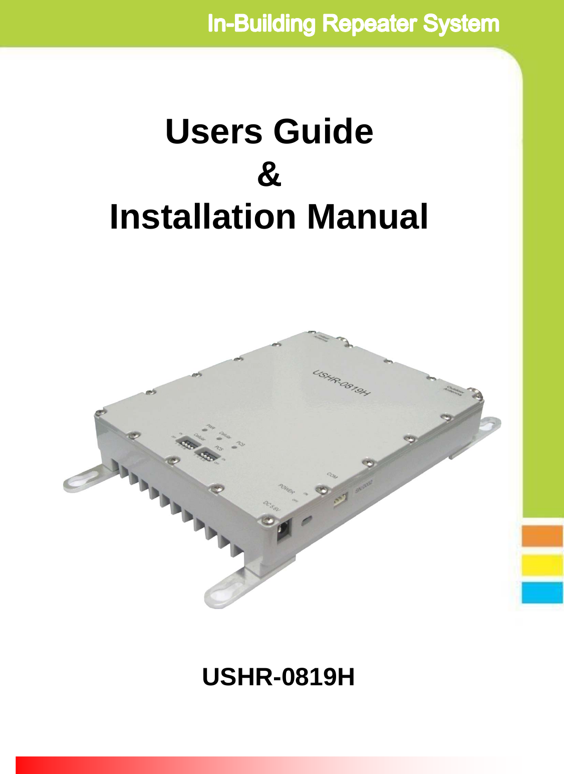
OPISYS orporated USHR-0819H Dual Band Repeater User Manual

OPISYS Incorporated Dual Band Repeater Users Manual

Users Manual

Users Guide&Installation ManualUSHR-0819H
Page 2- Content -1. General Information2. System Components3. Installation4. Trouble Shooting5. Specification6. Certificates7. MemoThis device complies with Part 15 of the FCC Rules. Operation is subject to the following conditions; This device complies with the Industry Canada license-exempt RSS standard(s). Operation is subject to the following conditions;(1) This device may not cause harmful interference.(2) This device must accept any interference received, including interference that may cause undesired operation.CAUTION: Changes or modifications not expressly approved by the party responsible for compliance could void the user’s authority to operate this device.Statement : The term “IC” before the radio certification number only signifies that Industry Canada technical specifications were met.CAUTION : The User that modifications to the unit may void the user’s authority to operate this device.To maintain compliance with RF energy exposure guidelines, the antenna used for this transmitter must be maintained a separation distance of at least 20cm from the user body when transmitting. Co-located or operated in conjunction with any other antenna or transmitter is prohibited.
Page 31. General Information1.1. Precautions1.1.1  Do not drop the device - It may damage the product and its function1.1.2  Do not place near magnetic material- It may cause of possible malfunction1.1.3  Product is recommended to be used with original AC/DC adapter1.1.4  Install the product where it is recommended- It may not properly operate if it is not recommended location1.1.5  Do not disassemble/ repair the product- Warranty may void once you disassemble the product. 1.1.6  Turn off the device immediately if a smog or any strange odor is detected from the product. 1.1.7  Use contained bolt to install on the wall.  Make sure it is safely installed before operation      Reference : Direction/Information for the proper operationCautions : Information for users to avoid malfunctionsWarning : Instruction for users to avoid unexpected hazard
1.2 . Features1.2.1.  SummaryThis device may be installed on residential area, office, warehouse etc. .Following is advantage of using in-building repeater system.This is RF type amplifier for Cellular800MHz and PCS1900MHz  signal enhancement.  It covers GSM, EDGE, CDMA, WCDMA  mobile phone users.(Please refer repeater specification for operating Frequency Range info.)1.2.2 .  FeaturesPage 4I. Decrease dropped call rateII. Increase signal strengthIII. Improve Data  / Voice  qualityIV. Prolong  hand phone battery  life V. Improve data Communication Rate I. Wider Coverage area- Gain 75dB .II. ALC(Automatic output  Level Control)- Stabilize operation in any  radio environmentIII. Fulfill  IS-95A spurious specification at +20dBm output power- Provide  high Data Communication Rate IV. Easy gain control by dip switch located on the front side of  productV. Support dual band - enable to connect  service from multiple carrier simultaneously- 800MHz / 1900MHz  service simultaneously- 800MHz / 1900MHz  adopt independent operation algorithmVI. Check status of product by LED indicatorVII. Manage and control product by GUI(Graphic User Interface)- Please ask professional installer about GUI ProgramVIII. Enable to stay connected in homes and offices- Please ask professional installer for installation on homes & officesIX. GSM, EDGE, CDMA, WCDMA  ready
Page 5①Dual Band Repeater ②AC/DC Adapter③User Manual2. System components④Installation bolts ① Dual band Repeater : BTS and mobile phone signal booster② AC/DC Adaptor : 110v power supply③ User Manual : Operation manual④ Installation Bolts : Holds repeater on the vertical wall
Page 63. Installation3.1. Installation diagram     3.2. Repeater Service ANTPortDonor ANT PortCellularStatus LEDPOWERLEDCellularGain controlDip Switch PCSGain controlDip SwitchPOWER JackPortPowerON/OFF SwitchPCSStatus LEDGUIPORTInstallationBracket3.1.1. Install Donor Antenna on higher location to avoid any signalinterference.3.1.2. Install service antenna at appropriate location such as wall or roof ceiling. Make sure service antenna is not blocked by furniture or hope appliance.3.1.3. Use enclosed bolt to fix repeater on the wall and plug in poweradaptor.
Page 73.3.  Repeater and Antenna connection3.3.1. Connect donor antenna to RVS connector as shown below.3.3.2. Connect Service antenna to FWD connector as shown below.3.3.3. Plug in power adaptor to power outlet.
Page 83.3.4. Plug in AD/CD adaptor to connector listed as DC5.6V3.3.5. Once power is on, it will show 3 green LED light on the front ofproduct as shown below.
Page 94.1.1.  Power on status4.1.2.  Power off status4.1.3.  Cellular  normal operation condition4.1.4.  During normal Cellular  operation, it detects excessive input signal orit is under oscillation condition due to insufficient isolation between antennas4.1.5.  Due to excessive input signal or oscillation, it cut off circuit to protect hardware        4.1.6.  PCS normal operation condition4.1.7. During normal PCS  operation, it detects excessive input signal orit is under oscillation condition due to insufficient isolation between antennas4.1.8. Due to excessive input signal or oscillation, it cut off circuit to protect hardware4. Trouble Shooting4.1.  LED Status     Item GREEN LED RED LED ProblemReferencePWRON - See 4.1.1OFF OFF See 4.1.2CellularON - See 4.1.3- ON See 4.1.4OFF OFF See 4.1.5PCSON - See 4.1.6- ON See 4.1.7OFF OFF See 4.1.8
Page 10Item Specifications NoteOperatingFrequencyDown Link 1930 ~ 1990 MHz PCS1900 BW: 60MHzUp Link 1850 ~ 1910 MHzDown Link 869 ~ 894 MHz Cellular800BW: 25 MHzUp Link 824 ~ 849 MHzModulation Type GSM, EDGE, CDMA, WCDMAInput Power -33dBm maxOutput PowerDown Link +17dBm PCS1900Up Link +20dBmDown Link +17dBm Cellular800Up Link +20dBmGainDown Link 75dB (±1.0dB) PCS1900, Average Gain on 60MHz BWUp Link 75dB (±1.0dB)Down Link 75dB (±1.0dB) Cellular800, Average Gain on 25MHz BWUp Link 75dB (±1.0dB)Gain Control Range 25dB Could be changed Dip switch or GUIRipple < 6.5dB PCS1900< 4.5dB Cellular800Noise Figure < 6dB PCS1900 Uplink Max Gain< 5dB Cellular800 Uplink Max GainPropagation Delay 5us max PCS1900/ Cellular800VSWR ≤ 1.8 : 1 PCS1900/ Cellular800ALC Level Down Link +17dBm (±1dB) PCS1900/ Cellular800Up Link +20dBm (±1dB) PCS1900/ Cellular800Shutdown Level Down Link +19dBm (±1dB) PCS1900/ Cellular800Up Link +22dBm (±1dB) PCS1900/ Cellular800Spectrum Mask 750KHz -45dBc/30kHz Note1. Downlink CDMA 9CH SignalNote2. Uplink CDMA Reverse Signal1.98MHz -55dBc/30kHzSpurious9 ~ 150kHz -13dBm/30kHz150kHz ~ 30MHz -13dBm/30kHz30MHz ~ 1GHz -13dBm/30kHz1GHz ~ 12.75GHz -13dBm/30kHzFrequency Stability ≤ ±0.01ppm PCS1900/ Cellular800GUI Interface RS-232CAlarm & Status DisplayPWR Normal : Green,  Pwr turn off : Off Cellular Normal : Green,  Shutdown : Off,  Checking SD : RedPCS Normal : Green,  Shutdown : Off,  Checking SD : RedPower Consumption 5.5Vdc / 1.7AInput Voltage DC 5.6Vdc / 2.5A AC/DC AdapterRF Connector N-type Female5. Specification5.1. Amplifier Specification
Page 11Item Specifications NoteDimensions (L W H) 151mm x 191mm x 35mm(5.95 x 7.5 x 1.38 inch)Weight 2KgItem Specifications NoteTemperature -30 ~ 55℃(-22 ~ 131℉)Humidity 10 ~ 95%4. 2. Mechanical Specification4. 3. Environment SpecificationNo Items Spec1 AC input power 90VAC ~ 264VAC, 47Hz ~ 63Hz2 Output rated Voltage +5.5VDC/1.3A3 Voltage Current range 2.5A ~ 0.0 A4 Operation Temperature -30℃ ~ +55℃5 Operation humidity  10% ~ 90%4. 4. AC/DC Adaptor Specification
Page 125. Certificates5.1  FCC CertificationModel : USHR-0819H▪Certificate Date :  Oct. 2012                ▪Certificate Number:  Q4EUSHR-0819H5.2  IC Certification Model : USHR-0819H▪Certificate Date : Oct. 2012             ▪Certificate Number:  8605A-USHR0819H
Page 136. Memo
Guide de l'utilisateur&Manuel d’installationUSHR-0819H
Page 2- Table des matières -1. Informations générales2. Éléments du système inclus3. Installation4. Dépannage5. Spécifications6. Certificats7. MémoCet appareil est conforme au paragraphe 15 de la règlementation FCC. Sonfonctionnement est sujet aux conditions suivantes ; cet appareil est conforme à la licence Industry Canada-à l’exception des normes RSS. Son fonctionnement est sujet aux conditions suivantes ;(1) cet appareil ne provoque pas d’interférences nocives.(2) cet appareil doit supporter toutes les interférences reçues, dont les interférences pouvant provoquer un fonctionnement indésirable.ATTENTION : Tout changement ou modification non approuvé expressément par la partie responsable de sa conformité, annulera le droit d’utilisateur permettant de faire fonctionner cet appareil.Instruction : Le terme “IC” situé avant le numéro de certification radio indique uniquement que les spécifications techniques sont conformes à Industry Canada.ATTENTION : L'utilisateur apportant des modifications à l’appareil annulera le droit d’utilisateur permettant de faire fonctionner cet appareil.Afin de rester en conformité avec les directives RF sur l'exposition à l'énergie, l’antenne utilisée pour ce transmetteur doit être placée à une distance d’au moins 20cm de l'utilisateur lors de la transmission.Tout fonctionnement conjoint avec une autre antenne ou toute autre antenne/transmetteur ayant la même position est interdit.
Page 31. Informations générales1.1. Précautions1.1.1  Ne pas faire tomber l’appareil - Risque d’endommager l’appareil et son fonctionnement1.1.2  Ne pas installer près de source magnétique- Risque possible de mauvais fonctionnement1.1.3  Il est recommandé d’utiliser cet appareil avec l’adaptateur AC/DC fourni1.1.4  Installer l’appareil selon les recommandations-Peut ne pas fonctionner correctement si placé dans un lieu non recommand1.1.5  Ne pas démonter/ réparer l’appareil- La garantie sera annulée en cas de démontage de l'appareil. 1.1.6  Éteindre immédiatement l'appareil si une fumée ou une odeur suspecte se dégage de l’appareil. 1.1.7  Utiliser les vis fournies pour l’installation sur un mur. S’assurer desa bonne installation avant utilisation      Référence : Instruction/Information pour un fonctionnement correctATTENTION : Information aux utilisateurs afin d’éviter tout mauvais  fonctionnementAvertissement : Instruction aux utilisateurs afin d’éviter tout danger inattendu
1.2 . caractéristiques1.2.1.  SommaireCet appareil peut être installé dans des zones résidentielles, des bureaux, des entrepôts etc. .Voici une liste des avantages à se servir d’un Système de répéteur en intérieur.Cet appareil est un amplificateur de type RF servant à améliorer le signal des portables 800MHz et PCS1900MHz.  Il couvre les utilisateurs de téléphone mobile GSM, EDGE, CDMA, WCDMA.(Veuillez vous référer aux spécifications du répéteur pour les plages des fréquences de fonctionnement.)1.2.2 .  caractéristiquesPage 4I. Baisse le taux d’appels déconnectésII. Renforce le signalIII. Améliore la qualité des données  / VoixIV. Prolonge la durée de vie des batteries des téléphones portables V.    Améliore le taux de transmission de données     I. Zone de couverture plus étendue- Gain 75dB .II. ALC(Niveau de réglage de sortie automatique)- Stabilise le fonctionnement pour tout environnement radioIII. Conforme aux spécifications sur les parasites IS-95A avec une puissance de sortie à +20dBm- Offre un taux de transmission de données élevéIV. Commande  de gain simple par commutateur DIP situé sur la façade avant de l’appareilV. Compatible double bande- permet de se connecter simultanément à un service à partir de multiples profils- service simultané 800MHz / 1900MHz- 800MHz / 1900MHz  adopte un algorithme de fonctionnement indépendant VI. Vérification de l’état de l'appareil grâce à un indicateur LEDVII. Gestion et contrôle de l'appareil par GUI(Interface Graphique Utilisateur)- Veuillez vous renseigner auprès d’un installateur professionnel en ce qui concerne le programme GUIVIII. permet de rester connecté à la maison et au bureau- Veuillez vous renseigner auprès d’un installateur professionnel pour une installation à la maison & au bureauIX. Compatible GSM, EDGE, CDMA, WCDMA
Page 5①Répéteur double bande ②Adaptateur AC/DC③Guide de l'utilisateur2. Éléments du système inclus④Vis d’installation ① Répéteur double bande : amplificateur de signal BTS et téléphone portable② Adaptateur AC/DC : fonctionne sur 110v③ Guide de l'utilisateur : manuel d’utilisation④ Vis d’installation : fixe le répéteur sur un mur vertical
Page 63. Installation3.1. Schéma d’installation3.2. répéteur Port ANT Service Port ANT extérieureLED du statut CellulaireLED POWERCommutateurDIPcontrôle de gain cellulaireCommutateurDIPcontrôlede gain PCSPortPOWER JackCommutateurON/OFF LED du statutPCSPORTGUIPatte de fixation3.1.1. Installer l’antenne extérieure sur un point élevé afin d’éviter toute interférence de signal.3.1.2. Installer l’antenne de service à un endroit approprié, tel qu’un mur ou un plafond. S’assurer que l’antenne n’est pas bloquée par un meuble ou un appareil domestique.3.1.3. Utiliser les vis fournies pour installer le répéteur sur un mur et brancher l’adaptateur.
Page 73.3. Connexion du répéteur et de l’antenne3.3.1. Connecter l’antenne extérieure au connecteur RVS tel qu'indiqué ci-dessous.3.3.2. Connecter l’antenne de service au connecteur FWD tel qu'indiqué ci-dessous.3.3.3. Brancher l’adaptateur sur une prise électrique.
Page 83.3.4. Brancher l’adaptateur AC/DC sur le connecteur référencé DC5.6V3.3.5. Une fois branché, 3 LED vertes vont s’allumer sur la façade avant de l’appareil, tel qu'indiqué ci-dessous.
Page 94.1.1.  État : allumé4.1.2.  État : éteint4.1.3. Conditions normales de fonctionnement du cellulaire4.1.4.  Au cours du fonctionnement normal du cellulaire, celui-ci détecte les signaux entrants excessifs ou les situations d'oscillation dues à une isolation insuffisante entre les antennes4.1.5.  A cause de signaux entrants excessifs ou d’oscillations, le circuit se coupe pour protéger les composants    4.1.6. Conditions normales de fonctionnement PCS4.1.7. Au cours du fonctionnement normal du PCS, celui-ci détecte les signaux entrants excessifs ou les situations d'oscillation dues à une isolation insuffisante entre les antennes4.1.8 A cause de signaux entrants excessifs ou d’oscillations, le circuit se coupe pour protéger les composants4. Dépannage4.1.  Statut LED     Élément LED VERTE LED ROUGE Référence ProblèmePWRON - Voir 4.1.1OFF OFF Voir 4.1.2CellulaireON - Voir 4.1.3- ON Voir 4.1.4OFF OFF Voir 4.1.5PCSON - Voir 4.1.6- ON Voir 4.1.7OFF OFF Voir 4.1.8
Page 10Élément Spécifications NoteFréquence de fonctionnementLiaison descendante 1930 ~ 1990 MHz PCS1900 BW: 60MHzLiaison montante 1850 ~ 1910 MHzLiaison descendante 869 ~ 894 MHz Cellular800BW: 25 MHzLiaison montante 824 ~ 849 MHzType de modulation GSM, EDGE, CDMA, WCDMAPuissance d'entrée -33dBm maxPuissance de sortieLiaison descendante +17dBmPCS1900Liaison montante +20dBmLiaison descendante +17dBmCellular800Liaison montante +20dBmGainLiaison descendante 75dB (±1.0dB)PCS1900, Gain moyen sur 60MHz BWLiaison montante 75dB (±1.0dB)Liaison descendante 75dB (±1.0dB)Cellular800, Gain moyen sur 25MHz BWLiaison montante 75dB (±1.0dB)Contrôle de plage de gain 25dB Peut être remplacé par commutateur DIPou GUIOndulation < 6.5dB PCS1900< 4.5dB Cellular800Facteur de bruit < 6dB PCS1900 Gain max liaison montante< 5dB Cellular800 Gain max liaison montanteTemps de propagation 5us max PCS1900/ Cellular800VSWR ≤ 1.8 : 1 PCS1900/ Cellular800Niveau ALCLiaison descendante +17dBm (±1dB) PCS1900/ Cellular800Liaison montante +20dBm (±1dB) PCS1900/ Cellular800Niveau arrêtLiaison descendante +19dBm (±1dB) PCS1900/ Cellular800Liaison montante +22dBm (±1dB) PCS1900/ Cellular800Spectre750KHz -45dBc/30kHz Note1. Signal CDMA 9CH liaison descendanteNote2. Signal inversé CDMA liaison montante1.98MHz -55dBc/30kHzParasites9 ~ 150kHz -13dBm/30kHz150kHz ~ 30MHz -13dBm/30kHz30MHz ~ 1GHz -13dBm/30kHz1GHz ~ 12.75GHz -13dBm/30kHzStabilité de fréquence ≤ ±0.01ppm PCS1900/ Cellular800Interface GUI  RS-232CAlarme & Etat AffichagePWR Normal : Vert,  Arrêt : Off Cellulaire Normal : Vert,  Arrêt: Off,  Vérification SD : RougePCSNormal : Vert Arrêt: Off Vérification SD : Rouge5. Spécifications5.1. Spécifications de l’amplificateur
Page 11Appareil Spécifications NoteDimensions (L l H) 151mm x 191mm x 35mm(5.95 x 7.5 x 1.38 inch)Poids 2 KgÉlément Spécifications NoteTempérature -30 ~ 55℃ (-22 ~ 131℉)Humidité 10 ~ 95%4. 2. Spécifications de l’appareil4. 3. Spécifications du milieu No Éléments Spec1 Puissance d'entrée AC 90VAC ~ 264VAC, 47Hz ~ 63Hz2 Tension de sortie nominale +5.5VDC/1.3A3 Plage courant/tension 2.5A ~ 0.0 A4Température de fonctionnement -30℃ ~ +55℃5 Humidité en fonctionnement 10% ~ 90%4. 4. Spécifications de l’adaptateur AC/DC
Page 125. Certificats5.1 Certification FCCModèle : USHR-0819H▪Date du Certificat :  Oct. 2012                ▪Numéro de Certificat :  Q4EUSHR-0819H5.2  Certification ICModèle : USHR-0819H▪Date du Certificat : Oct. 2012             ▪Numéro du Certificat :  8605A-USHR0819H
Page 136. Mémo
Item SpecificationFrequency Range 824 ∼894 MHz 1750 ∼2400MHzVSWR ≥ 2.0 : 1  ≥ 1.5 : 1 Gain ≥ 4.0 dBi ≥ 7.0 dBiHorizontal-3dB half power angle 90°±40° 60°± 20 °F/B ratio (@180±30°)  5 dB 10 dBVertical-3dB half power angle 90°±40° 60°± 20 °F/B ratio (@180±30°)  5 dB 10 dBImpedance 50 ΩPartiality Vertical3th, 5th IMD (2 x5W) ≥3차 -140 dBc≥ 5차 -160 dBcMaximum Power 10 WConnector Type N – Female x 1 (Cable 300 mm)Maximum Wind Pressure 30 m/sDimension (W x D x H) 150 × 170 × 45 mmWeight  0.8 ㎏Vibration (Grms) 3◆ Specification◆Photo◆Layout◆ Beam Patten수평수직Model Name : PAT-CPWI-M Service Antenna Specification
◆ Specification◆Photo◆Layout◆ Beam Patten수평수직Donor Antenna SpecificationModel Name : ALP-15QD-M Item SpecificationFrequency Range 824 ∼894 MHz 1750 ∼2400MHzVSWR ≥ 1.8 : 1  ≥ 1.5 : 1 Gain ≥ 5.0 dBi ≥ 11.0 dBiHorizontal-3dB half power angle 80° ~ 130° 40° ~ 60°F/B ratio (@180±30°)  4 dB 15 dBVertical-3dB half power angle 50° ~ 90° 35° ~ 55°F/B ratio (@180±30°)  4 dB  150 dB Impedance 50 ΩPartiality Vertical3th, 5th IMD (2 x5W) ≥3차 -140 dBc≥ 5차 -160 dBcMaximum Power 100 WConnector Type N – Female x 1 Maximum Wind Pressure 60 m/sDimension (W x D x H) 110 × 480 × 45 mmWeight  1.8 ㎏Vibration (Grms) 5

Navigation menu