OPISYS orporated USHR-0819H Dual Band Repeater User Manual
OPISYS Incorporated Dual Band Repeater Users Manual
Users Manual
Users Guide
&
Installation Manual
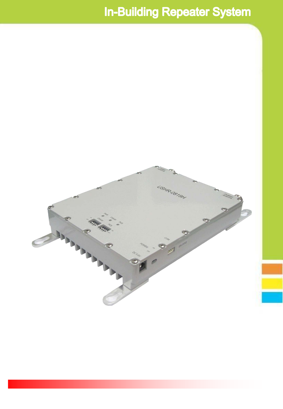
USHR-0819H

Page 2
- Content -
1. General Information
2. System Components
3. Installation
4. Trouble Shooting
5. Specification
6. Certificates
7. Memo
This device complies with Part 15 of the FCC Rules. Operation is subject to the following
conditions; This device complies with the Industry Canada license-exempt RSS standard(s).
Operation is subject to the following conditions;
(1) This device may not cause harmful interference.
(2) This device must accept any interference received, including interference that may
cause undesired operation.
CAUTION: Changes or modifications not expressly approved by the party responsible for
compliance could void the user’s authority to operate this device.
Statement : The term “IC” before the radio certification number only signifies that Industry
Canada technical specifications were met.
CAUTION : The User that modifications to the unit may void the user’s authority to operate
this device.
To maintain compliance with RF energy exposure guidelines, the antenna used for this
transmitter must be maintained a separation distance of at least 20cm from the user body
when transmitting.
Co-located or operated in conjunction with any other antenna or transmitter is prohibited.

Page 3
1. General Information
1.1. Precautions
1.1.1 Do not drop the device
- It may damage the product and its function
1.1.2 Do not place near magnetic material
- It may cause of possible malfunction
1.1.3 Product is recommended to be used with original AC/DC adapter
1.1.4 Install the product where it is recommended
- It may not properly operate if it is not recommended location
1.1.5 Do not disassemble/ repair the product
- Warranty may void once you disassemble the product.
1.1.6 Turn off the device immediately if a smog or any strange odor is
detected from the product.
1.1.7 Use contained bolt to install on the wall. Make sure it is safely
installed before operation
Reference : Direction/Information for the proper operation
Cautions : Information for users to avoid malfunctions
Warning : Instruction for users to avoid unexpected hazard
1.2 . Features
1.2.1. Summary
This device may be installed on residential area, office, warehouse etc. .
Following is advantage of using in-building repeater system.
This is RF type amplifier for Cellular800MHz and PCS1900MHz signal
enhancement. It covers GSM, EDGE, CDMA, WCDMA mobile phone users.
(Please refer repeater specification for operating Frequency Range info.)
1.2.2 . Features
Page 4
I. Decrease dropped call rate
II. Increase signal strength
III. Improve Data / Voice quality
IV. Prolong hand phone battery life
V. Improve data Communication Rate
I. Wider Coverage area
- Gain 75dB .
II. ALC(Automatic output Level Control)
- Stabilize operation in any radio environment
III. Fulfill IS-95A spurious specification at +20dBm output power
- Provide high Data Communication Rate
IV. Easy gain control by dip switch located on the front side of product
V. Support dual band
- enable to connect service from multiple carrier simultaneously
- 800MHz / 1900MHz service simultaneously
- 800MHz / 1900MHz adopt independent operation algorithm
VI. Check status of product by LED indicator
VII. Manage and control product by GUI(Graphic User Interface)
- Please ask professional installer about GUI Program
VIII. Enable to stay connected in homes and offices
- Please ask professional installer for installation on homes & offices
IX. GSM, EDGE, CDMA, WCDMA ready

Page 5
①Dual Band Repeater ②AC/DC Adapter
③User Manual
2. System components
④Installation bolts
① Dual band Repeater : BTS and mobile phone signal booster
② AC/DC Adaptor : 110v power supply
③ User Manual : Operation manual
④ Installation Bolts : Holds repeater on the vertical wall

Page 6
3. Installation
3.1. Installation diagram
3.2. Repeater
Service ANT
Port
Donor ANT
Port
Cellular
Status LED
POWER
LED
Cellular
Gain control
Dip Switch PCS
Gain control
Dip Switch
POWER Jack
Port
Power
ON/OFF
Switch
PCS
Status LED
GUI
PORT
Installation
Bracket
3.1.1. Install Donor Antenna on higher location to avoid any signal
interference.
3.1.2. Install service antenna at appropriate location such as wall or
roof ceiling. Make sure service antenna is not blocked by
furniture or hope appliance.
3.1.3. Use enclosed bolt to fix repeater on the wall and plug in power
adaptor.

Page 7
3.3. Repeater and Antenna connection
3.3.1. Connect donor antenna to RVS connector as shown below.
3.3.2. Connect Service antenna to FWD connector as shown below.
3.3.3. Plug in power adaptor to power outlet.

Page 8
3.3.4. Plug in AD/CD adaptor to connector listed as DC5.6V
3.3.5. Once power is on, it will show 3 green LED light on the front of
product as shown below.
Page 9
4.1.1. Power on status
4.1.2. Power off status
4.1.3. Cellular normal operation condition
4.1.4. During normal Cellular operation, it detects excessive input signal or
it is under oscillation condition due to insufficient isolation between
antennas
4.1.5. Due to excessive input signal or oscillation, it cut off circuit to protect
hardware
4.1.6. PCS normal operation condition
4.1.7. During normal PCS operation, it detects excessive input signal or
it is under oscillation condition due to insufficient isolation between
antennas
4.1.8. Due to excessive input signal or oscillation, it cut off circuit to protect
hardware
4. Trouble Shooting
4.1. LED Status
Item GREEN LED RED LED Problem
Reference
PWR
ON - See 4.1.1
OFF OFF See 4.1.2
Cellular
ON - See 4.1.3
- ON See 4.1.4
OFF OFF See 4.1.5
PCS
ON - See 4.1.6
- ON See 4.1.7
OFF OFF See 4.1.8

Page 10
Item Specifications Note
Operating
Frequency
Down Link 1930 ~ 1990 MHz PCS1900
BW: 60MHz
Up Link 1850 ~ 1910 MHz
Down Link 869 ~ 894 MHz Cellular800
BW: 25 MHz
Up Link 824 ~ 849 MHz
Modulation Type GSM, EDGE, CDMA, WCDMA
Input Power -33dBm max
Output Power
Down Link +17dBm PCS1900
Up Link +20dBm
Down Link +17dBm Cellular800
Up Link +20dBm
Gain
Down Link 75dB (±1.0dB) PCS1900, Average Gain on 60MHz BW
Up Link 75dB (±1.0dB)
Down Link 75dB (±1.0dB) Cellular800, Average Gain on 25MHz BW
Up Link 75dB (±1.0dB)
Gain Control Range 25dB Could be changed Dip switch or GUI
Ripple < 6.5dB PCS1900
< 4.5dB Cellular800
Noise Figure < 6dB PCS1900 Uplink Max Gain
< 5dB Cellular800 Uplink Max Gain
Propagation Delay 5us max PCS1900/ Cellular800
VSWR ≤ 1.8 : 1 PCS1900/ Cellular800
ALC Level Down Link +17dBm (±1dB) PCS1900/ Cellular800
Up Link +20dBm (±1dB) PCS1900/ Cellular800
Shutdown Level Down Link +19dBm (±1dB) PCS1900/ Cellular800
Up Link +22dBm (±1dB) PCS1900/ Cellular800
Spectrum Mask 750KHz -45dBc/30kHz Note1. Downlink CDMA 9CH Signal
Note2. Uplink CDMA Reverse Signal
1.98MHz -55dBc/30kHz
Spurious
9 ~ 150kHz -13dBm/30kHz
150kHz ~ 30MHz -13dBm/30kHz
30MHz ~ 1GHz -13dBm/30kHz
1GHz ~ 12.75GHz -13dBm/30kHz
Frequency Stability ≤ ±0.01ppm PCS1900/ Cellular800
GUI Interface RS-232C
Alarm & Status Display
PWR Normal : Green, Pwr turn off : Off
Cellular Normal : Green, Shutdown : Off, Checking SD : Red
PCS Normal : Green, Shutdown : Off, Checking SD : Red
Power Consumption 5.5Vdc / 1.7A
Input Voltage DC 5.6Vdc / 2.5A AC/DC Adapter
RF Connector N-type Female
5. Specification
5.1. Amplifier Specification
Page 11
Item Specifications Note
Dimensions (L W H) 151mm x 191mm x 35mm
(5.95 x 7.5 x 1.38 inch)
Weight 2Kg
Item Specifications Note
Temperature -30 ~ 55℃(-22 ~ 131℉)
Humidity 10 ~ 95%
4. 2. Mechanical Specification
4. 3. Environment Specification
No Items Spec
1 AC input power 90VAC ~ 264VAC, 47Hz ~ 63Hz
2 Output rated Voltage +5.5VDC/1.3A
3 Voltage Current range 2.5A ~ 0.0 A
4 Operation Temperature -30℃ ~ +55℃
5 Operation humidity 10% ~ 90%
4. 4. AC/DC Adaptor Specification

Page 12
5. Certificates
5.1 FCC Certification
Model : USHR-0819H
▪Certificate Date : Oct. 2012
▪Certificate Number: Q4EUSHR-0819H
5.2 IC Certification
Model : USHR-0819H
▪Certificate Date : Oct. 2012
▪Certificate Number: 8605A-USHR0819H

Page 13
6. Memo

Guide de l'utilisateur
&
Manuel d’installation
USHR-0819H

Page 2
- Table des matières -
1. Informations générales
2. Éléments du système inclus
3. Installation
4. Dépannage
5. Spécifications
6. Certificats
7. Mémo
Cet appareil est conforme au paragraphe 15 de la règlementation FCC. Son
fonctionnement est sujet aux conditions suivantes ; cet appareil est conforme à la licence
Industry Canada-à l’exception des normes RSS.
Son fonctionnement est sujet aux conditions suivantes ;
(1) cet appareil ne provoque pas d’interférences nocives.
(2) cet appareil doit supporter toutes les interférences reçues, dont les interférences
pouvant provoquer un fonctionnement indésirable.
ATTENTION : Tout changement ou modification non approuvé expressément par la partie
responsable de sa conformité, annulera le droit d’utilisateur permettant de faire
fonctionner cet appareil.
Instruction : Le terme “IC” situé avant le numéro de certification radio indique uniquement
que les spécifications techniques sont conformes à Industry Canada.
ATTENTION : L'utilisateur apportant des modifications à l’appareil annulera le droit
d’utilisateur permettant de faire fonctionner cet appareil.
Afin de rester en conformité avec les directives RF sur l'exposition à l'énergie, l’antenne
utilisée pour ce transmetteur doit être placée à une distance d’au moins 20cm de
l'utilisateur lors de la transmission.
Tout fonctionnement conjoint avec une autre antenne ou toute autre antenne/transmetteur
ayant la même position est interdit.
Page 3
1. Informations générales
1.1. Précautions
1.1.1 Ne pas faire tomber l’appareil
- Risque d’endommager l’appareil et son fonctionnement
1.1.2 Ne pas installer près de source magnétique
- Risque possible de mauvais fonctionnement
1.1.3 Il est recommandé d’utiliser cet appareil avec l’adaptateur AC/DC fourni
1.1.4 Installer l’appareil selon les recommandations
-Peut ne
p
as fonctionner correctement si
p
lacé dans un lieu non recomman
d
1.1.5 Ne pas démonter/ réparer l’appareil
- La garantie sera annulée en cas de démontage de l'appareil.
1.1.6 Éteindre immédiatement l'appareil si une fumée ou une odeur suspecte
se dégage de l’appareil.
1.1.7 Utiliser les vis fournies pour l’installation sur un mur. S’assurer de
sa bonne installation avant utilisation
Référence : Instruction/Information pour un fonctionnement correct
ATTENTION : Information aux utilisateurs afin d’éviter tout mauvais
fonctionnement
Avertissement : Instruction aux utilisateurs afin d’éviter tout danger
inattendu
1.2 . caractéristiques
1.2.1. Sommaire
Cet appareil peut être installé dans des zones résidentielles, des bureaux, des
entrepôts etc. .
Voici une liste des avantages à se servir d’un Système de répéteur en intérieur.
Cet appareil est un amplificateur de type RF servant à améliorer le signal des
portables 800MHz et PCS1900MHz. Il couvre les utilisateurs de téléphone mobile GSM,
EDGE, CDMA, WCDMA.
(Veuillez vous référer aux spécifications du répéteur pour les plages des
fréquences de fonctionnement.)
1.2.2 . caractéristiques
Page 4
I. Baisse le taux d’appels déconnectés
II. Renforce le signal
III. Améliore la qualité des données / Voix
IV. Prolonge la durée de vie des batteries
des téléphones portables
V. Améliore le taux de transmission de données
I. Zone de couverture plus étendue
- Gain 75dB .
II. ALC(Niveau de réglage de sortie automatique)
- Stabilise le fonctionnement pour tout environnement radio
III. Conforme aux spécifications sur les parasites IS-95A avec une
puissance de sortie à +20dBm
- Offre un taux de transmission de données élevé
IV. Commande de gain simple par commutateur DIP situé sur la façade
avant de l’appareil
V. Compatible double bande
- permet de se connecter simultanément à un service à partir de
multiples profils
- service simultané 800MHz / 1900MHz
- 800MHz / 1900MHz adopte un algorithme de fonctionnement
indépendant
VI. Vérification de l’état de l'appareil grâce à un indicateur LED
VII. Gestion et contrôle de l'appareil par GUI(Interface Graphique
Utilisateur)
- Veuillez vous renseigner auprès d’un installateur professionnel en
ce qui concerne le programme GUI
VIII. permet de rester connecté à la maison et au bureau
- Veuillez vous renseigner auprès d’un installateur professionnel
pour une installation à la maison & au bureau
IX. Compatible GSM, EDGE, CDMA, WCDMA

Page 5
①Répéteur double bande ②Adaptateur AC/DC
③Guide de l'utilisateur
2. Éléments du système inclus
④Vis d’installation
① Répéteur double bande : amplificateur de signal BTS et téléphone
portable
② Adaptateur AC/DC : fonctionne sur 110v
③ Guide de l'utilisateur : manuel d’utilisation
④ Vis d’installation : fixe le répéteur sur un mur vertical

Page 6
3. Installation
3.1. Schéma d’installation
3.2. répéteur
Port ANT
Service
Port ANT
extérieure
LED du
statut
Cellulaire
LED
POWER
Commutateu
rDIP
contrôle de
gain
cellulaire
Commutateur
DIPcontrôle
de gain PCS
Port
POWER Jack
Commutateur
ON/OFF
LED du statut
PCS
PORT
GUI
Patte de
fixation
3.1.1. Installer l’antenne extérieure sur un point élevé afin d’éviter toute
interférence de signal.
3.1.2. Installer l’antenne de service à un endroit approprié, tel qu’un
mur ou un plafond. S’assurer que l’antenne n’est pas bloquée par un
meuble ou un appareil domestique.
3.1.3. Utiliser les vis fournies pour installer le répéteur sur un mur et
brancher l’adaptateur.
Page 7
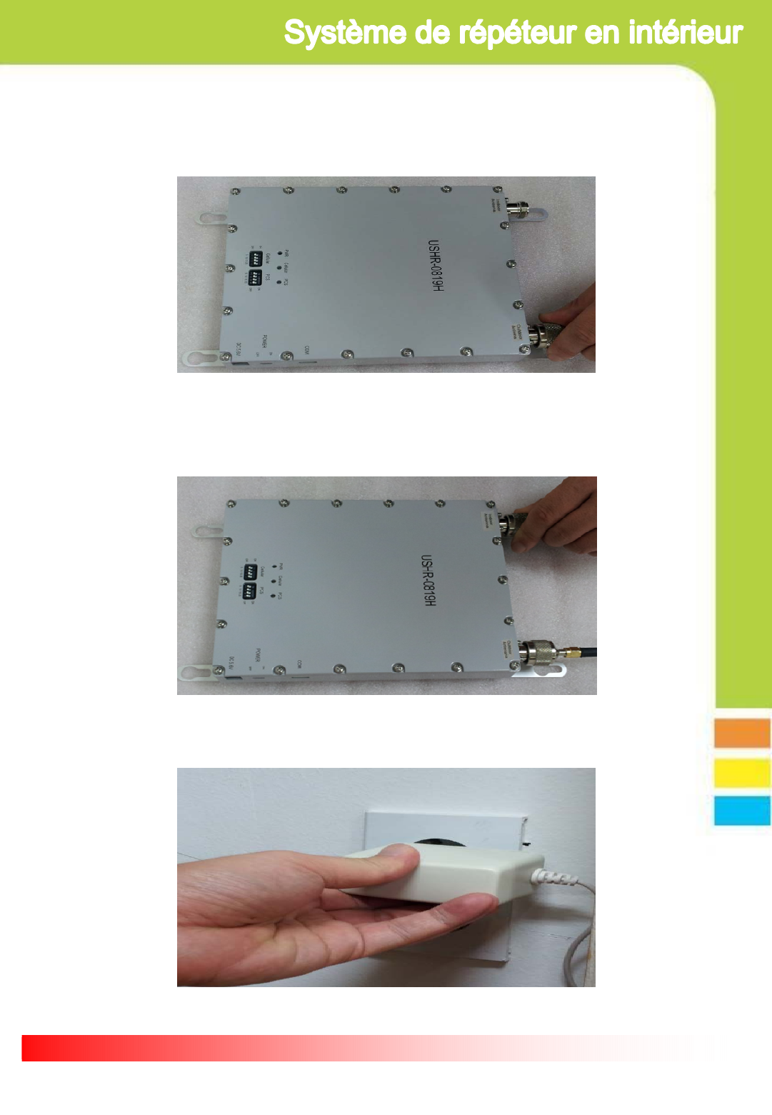
3.3. Connexion du répéteur et de l’antenne
3.3.1. Connecter l’antenne extérieure au connecteur RVS tel qu'indiqué
ci-dessous.
3.3.2. Connecter l’antenne de service au connecteur FWD tel
qu'indiqué ci-dessous.
3.3.3. Brancher l’adaptateur sur une prise électrique.

Page 8
3.3.4. Brancher l’adaptateur AC/DC sur le connecteur référencé
DC5.6V
3.3.5. Une fois branché, 3 LED vertes vont s’allumer sur la façade
avant de l’appareil, tel qu'indiqué ci-dessous.

Page 9
4.1.1. État : allumé
4.1.2. État : éteint
4.1.3. Conditions normales de fonctionnement du cellulaire
4.1.4. Au cours du fonctionnement normal du cellulaire, celui-ci détecte les
signaux entrants excessifs ou les situations d'oscillation dues à une isolation
insuffisante entre les antennes
4.1.5. A cause de signaux entrants excessifs ou d’oscillations, le circuit se
coupe pour protéger les composants
4.1.6. Conditions normales de fonctionnement PCS
4.1.7. Au cours du fonctionnement normal du PCS, celui-ci détecte les
signaux entrants excessifs ou les situations d'oscillation dues à une isolation
insuffisante entre les antennes
4.1.8 A cause de signaux entrants excessifs ou d’oscillations, le circuit se
coupe pour protéger les composants
4. Dépannage
4.1. Statut LED
Élément LED VERTE LED ROUGE Référence
Problème
PWR
ON - Voir 4.1.1
OFF OFF Voir 4.1.2
Cellulaire
ON - Voir 4.1.3
- ON Voir 4.1.4
OFF OFF Voir 4.1.5
PCS
ON - Voir 4.1.6
- ON Voir 4.1.7
OFF OFF Voir 4.1.8
Page 10
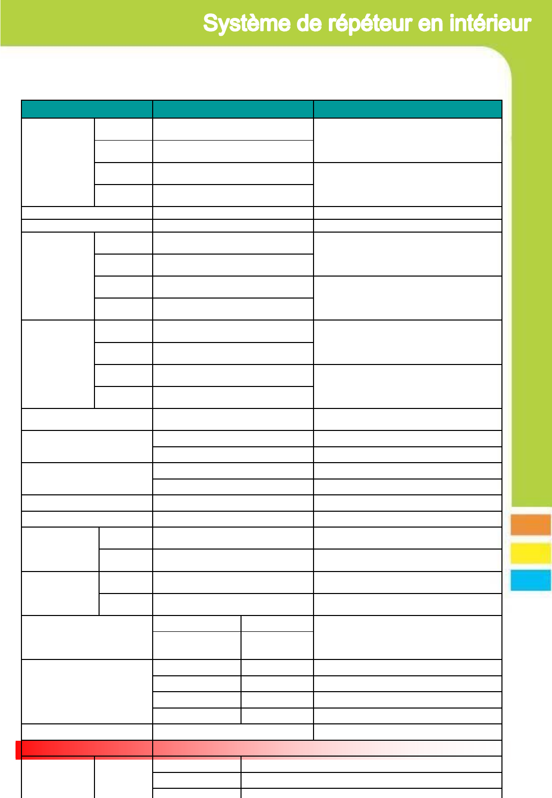
Élément Spécifications Note
Fréquence de fo
nctionnement
Liaison desc
endante 1930 ~ 1990 MHz PCS1900
BW: 60MHzLiaison mon
tante 1850 ~ 1910 MHz
Liaison desc
endante 869 ~ 894 MHz Cellular800
BW: 25 MHzLiaison mon
tante 824 ~ 849 MHz
Type de modulation GSM, EDGE, CDMA, WCDMA
Puissance d'entrée -33dBm max
Puissance de so
rtie
Liaison desc
endante +17dBm
PCS1900
Liaison mon
tante +20dBm
Liaison desc
endante +17dBm
Cellular800
Liaison mon
tante +20dBm
Gain
Liaison desc
endante 75dB (±1.0dB)
PCS1900, Gain moyen sur 60MHz BW
Liaison mon
tante 75dB (±1.0dB)
Liaison desc
endante 75dB (±1.0dB)
Cellular800, Gain moyen sur 25MHz BW
Liaison mon
tante 75dB (±1.0dB)
Contrôle de plage de gain 25dB Peut être remplacé par commutateur DIP
ou GUI
Ondulation < 6.5dB PCS1900
< 4.5dB Cellular800
Facteur de bruit < 6dB PCS1900 Gain max liaison montante
< 5dB Cellular800 Gain max liaison montante
Temps de propagation 5us max PCS1900/ Cellular800
VSWR ≤ 1.8 : 1 PCS1900/ Cellular800
Niveau ALC
Liaison des
cendante +17dBm (±1dB) PCS1900/ Cellular800
Liaison mo
ntante +20dBm (±1dB) PCS1900/ Cellular800
Niveau arrêt
Liaison des
cendante +19dBm (±1dB) PCS1900/ Cellular800
Liaison mo
ntante +22dBm (±1dB) PCS1900/ Cellular800
Spectre
750KHz -45dBc/30kHz Note1. Signal CDMA 9CH liaison descenda
nte
Note2. Signal inversé CDMA liaison montan
te
1.98MHz -55dBc/30kHz
Parasites
9 ~ 150kHz -13dBm/30kHz
150kHz ~ 30MHz -13dBm/30kHz
30MHz ~ 1GHz -13dBm/30kHz
1GHz ~ 12.75GHz -13dBm/30kHz
Stabilité de fréquence ≤ ±0.01ppm PCS1900/ Cellular800
Interface GUI RS-232C
Alarme & Etat Affichage
PWR Normal : Vert, Arrêt : Off
Cellulaire Normal : Vert, Arrêt: Off, Vérification SD : Rouge
PCS
Normal : Vert Arrêt: Off Vérification SD : Rouge
5. Spécifications
5.1. Spécifications de l’amplificateur
Page 11
Appareil Spécifications Note
Dimensions (L l H) 151mm x 191mm x 35mm
(5.95 x 7.5 x 1.38 inch)
Poids 2 Kg
Élément Spécifications Note
Température -30 ~ 55℃ (-22 ~ 131℉)
Humidité 10 ~ 95%
4. 2. Spécifications de l’appareil
4. 3. Spécifications du milieu
No Éléments Spec
1 Puissance d'entrée AC 90VAC ~ 264VAC, 47Hz ~ 63Hz
2 Tension de sortie nominale +5.5VDC/1.3A
3 Plage courant/tension 2.5A ~ 0.0 A
4Température de
fonctionnement -30℃ ~ +55℃
5 Humidité en fonctionnement 10% ~ 90%
4. 4. Spécifications de l’adaptateur AC/DC

Page 12
5. Certificats
5.1 Certification FCC
Modèle : USHR-0819H
▪Date du Certificat : Oct. 2012
▪Numéro de Certificat : Q4EUSHR-0819H
5.2 Certification IC
Modèle : USHR-0819H
▪Date du Certificat : Oct. 2012
▪Numéro du Certificat : 8605A-USHR0819H

Page 13
6. Mémo
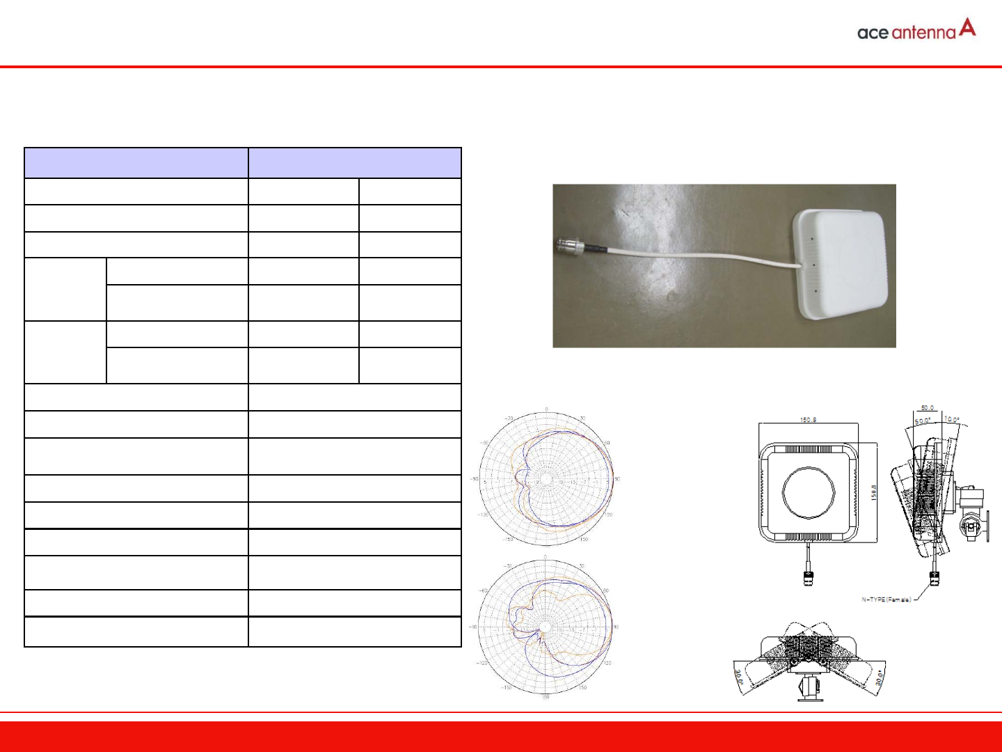
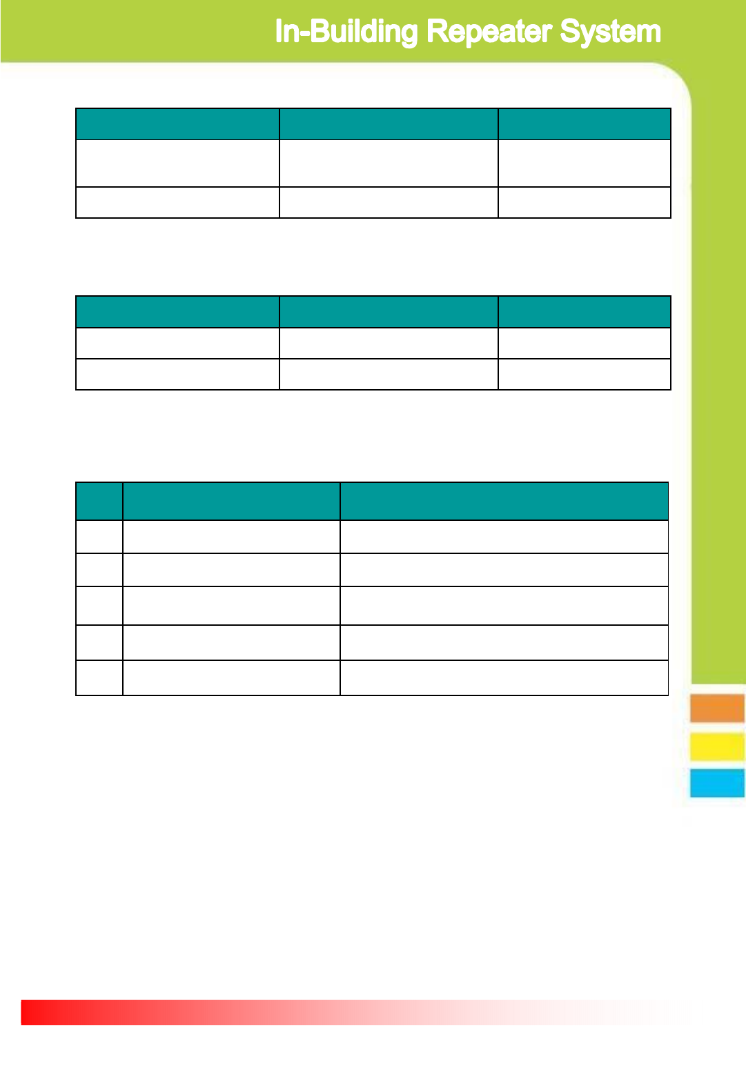
Item Specification
Frequency Range 824 ∼894 MHz 1750 ∼2400MHz
VSWR ≥ 2.0 : 1 ≥ 1.5 : 1
Gain ≥ 4.0 dBi ≥ 7.0 dBi
Horizontal
-3dB half power angle 90°±40° 60°± 20 °
F/B ratio (@180±30°) 5 dB 10 dB
Vertical
-3dB half power angle 90°±40° 60°± 20 °
F/B ratio (@180±30°) 5 dB 10 dB
Impedance 50 Ω
Partiality Vertical
3th, 5th IMD (2 x5W) ≥3차 -140 dBc
≥ 5차 -160 dBc
Maximum Power 10 W
Connector Type N – Female x 1 (Cable 300 mm)
Maximum Wind Pressure 30 m/s
Dimension (W x D x H) 150 × 170 × 45 mm
Weight 0.8 ㎏
Vibration (Grms) 3
◆ Specification
◆Photo
◆Layout
◆ Beam Patten
수평
수직
Model Name : PAT-CPWI-M
Service Antenna Specification
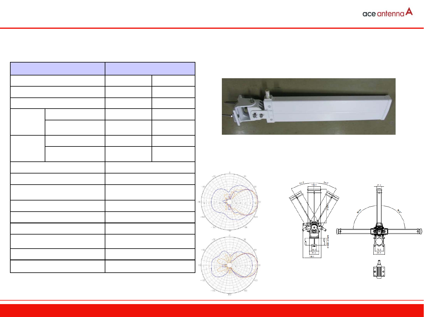
◆ Specification
◆Photo
◆Layout
◆ Beam Patten
수평
수직
Donor Antenna Specification
Model Name : ALP-15QD-M
Item Specification
Frequency Range 824 ∼894 MHz 1750 ∼2400MHz
VSWR ≥ 1.8 : 1 ≥ 1.5 : 1
Gain ≥ 5.0 dBi ≥ 11.0 dBi
Horizontal
-3dB half power angle 80° ~ 130° 40° ~ 60°
F/B ratio (@180±30°) 4 dB 15 dB
Vertical
-3dB half power angle 50° ~ 90° 35° ~ 55°
F/B ratio (@180±30°) 4 dB 150 dB
Impedance 50 Ω
Partiality Vertical
3th, 5th IMD (2 x5W) ≥3차 -140 dBc
≥ 5차 -160 dBc
Maximum Power 100 W
Connector Type N – Female x 1
Maximum Wind Pressure 60 m/s
Dimension (W x D x H) 110 × 480 × 45 mm
Weight 1.8 ㎏
Vibration (Grms) 5