ORBCOMM License ST6000 Mobile Satellite Earth Station Module User Manual T407 ST 6000 Hardware Guide
ORBCOMM License Corp. Mobile Satellite Earth Station Module T407 ST 6000 Hardware Guide
Users Manual

ST 6000
Hardware Guide
T407, Version 0.10 BETA
Sep 2017
© ORBCOMMInc.

ST 6000 - HARDWARE GUIDE
LEGAL NOTICE
This documentation is owned by ORBCOMM and protected by applicable copyright laws and international treaty
provisions. Other copyrighted names used are the property of their respective owners. Therefore, you must treat this
documentation like any other copyrighted material. This publication, or any part thereof, may not be reproduced or
transmitted in any form or by any means, electronic or mechanical, including photocopying, recording, storage in an
information retrieval system, or otherwise, without prior written permission by ORBCOMM, Inc. 395 W Passaic Street,
Suite 325, Rochelle Park, NJ 07662 USA Phone 703-433-6325. The information in this document is for information
purposes only and contains technical information and descriptions of the ORBCOMM product(s) and is subject to
change without notice. No warranty or representation, express or implied, is made with respect to its contents.
INMARSAT, the Inmarsat logo and IsatData Pro are trademarks of Inmarsat used under license by SkyWave (an
ORBCOMM company). Inmarsat is not responsible for the operation and regulatory compliance of the products and
services referred to in this document that connect to the Inmarsat system.
T407, VERSION 0.10 BETA
2
© ORBCOMM PROPRIETARY

ST 6000 - HARDWARE GUIDE
CONTACT INFORMATION
Visit ORBCOMM Online
www.ORBCOMM.com
Contact Customer Support
support@skywave.com
+1.613.836.2222
Headquarters
395 W Passaic Street, Suite 325
Rochelle Park, NJ 07662 USA
Tel: +1-703-433-6300
Fax: 1-703-433-6400
Email: sales@orbcomm.com
T407, VERSION 0.10 BETA
3
© ORBCOMM PROPRIETARY

ST 6000 - HARDWARE GUIDE
TABLE OF CONTENTS
Legal Notice 2
Contact Information 3
Contact Customer Support 3
TABLE OF CONTENTS 4
List of Figures 6
List of Tables 7
Preface 8
Purpose 8
Notation 8
Reference 8
1 Overview 9
1.1 Key Features and Benefits 9
2 Compliance 10
3 Specifications 12
3.1 Connectors 12
3.1.1 ST 6000 Connector Details 12
3.1.2 Mating Connector Details 12
3.1.3 ST 6000 Connector 13
3.1.4 Mating Connector 13
3.1.5 Connector Electrical Pin Assignment 14
3.2 Antenna 15
3.3 Power 15
3.3.1 Input Power 15
3.3.2 Power Consumption 16
3.3.3 Inrush Current 16
3.4 Input/Output 17
3.4.1 Input Bandwidth 18
3.4.2 Output Bandwidth 18
3.5 Serial Interfaces 18
3.5.1 Console/Auxiliary (RS-232) Interface 18
3.5.2 RS-485/J1708 Interface 19
3.6 Accelerometer/GNSS/Temperature Sensor 19
3.7 RF Specifications 19
3.7.1 Frequency 19
3.7.2 Antenna 19
3.8 GNSS 19
T407, VERSION 0.10 BETA
4
© ORBCOMM PROPRIETARY
ST 6000 - HARDWARE GUIDE
3.9 Accelerometer 20
3.10 Mechanical 22
3.10.1 Dimensions 22
3.10.2 Mass and UV Resistance 23
3.11 LED 23
3.12 Nonvolatile Storage 23
3.13 Environmental 24
3.13.1 Temperature 24
3.13.2 Environmental 24
4 Integration Guidelines 25
4.1 Enclosure Design 25
4.2 Ground Plane Requirements 25
4.3 Labeling 26
T407, VERSION 0.10 BETA
5
© ORBCOMM PROPRIETARY
ST 6000 - HARDWARE GUIDE
LIST OF FIGURES
Figure 1: ST 6000 9
Figure 2: ST 6000 Connector 13
Figure 3: Mating Connector 13
Figure 4: Onboard Antennas 15
Figure 5: Accelerometer Axis 21
Figure 6: ST 6000 Top View 22
Figure 7: ST 6000 Side View Dimensions (in.) 22
Figure 8: ST 6000 Bottom View Dimensions (in.) 23
Figure 9: Ground Plane Requirements (in.) 26
T407, VERSION 0.10 BETA
6
© ORBCOMM PROPRIETARY

ST 6000 - HARDWARE GUIDE
LIST OF TABLES
Table 1: Connector Details 12
Table 2: Mating Connector Details 12
Table 3: Electrical Pin Assignment (ST 6000) 14
Table 4: Input Power 16
Table 5: ST 6000 Power Consumption 16
Table 6: Inrush Current 17
Table 7: I/O Electrical Characteristics 17
Table 8: Analog Input Characteristics 18
Table 9: Electrical Characteristics 18
Table 10: Multi-GNSS Specifications 20
Table 11: Accelerometer Specifications 21
T407, VERSION 0.10 BETA
7
© ORBCOMM PROPRIETARY

ST 6000 - HARDWARE GUIDE
PREFACE
Purpose
This document provides an overview of the hardware characteristics and specifications for the 20-pin ST 6000.
Notation
An OEM Integrator is an ORBCOMM customer who purchases an ST 6000 for integration into their own enclosure. To
become an OEM Integrator certain commercial criteria must be met. Contact your Account Executive for further
details.
Hardware components and hardware stickers in this document might not be exactly as shown and are subject to
change without notice.
CAUTION: This safety symbol warns of possible hazards to personnel, equipment, or both. It includes
hazards that will or can cause personal injury, property damage, or death if the hazard is not
avoided.
Note: A note indicates information with no potential hazard. A note indicates points of interest or provides
supplementary information about a feature or task.
Numbered lists indicate a series of steps required to complete a task or function.
Bulleted lists highlight information where order or sequence is not crucial.
Reference
The content of the following documents may be useful in conjunction with this guide. These documents are
available from the ORBCOMM Developer Toolkit (hereafter referred to as the Toolkit) or customer support.
[T404] LSF Developer Guide for FW v3.x
[T405] IsatData Pro Service API Reference for FW v3.x
T407, VERSION 0.10 BETA
8
© ORBCOMM PROPRIETARY
ST 6000 - HARDWARE GUIDE
1 OVERVIEW
The ST 6000 provides a high performance, low latency, two-way communication solution that uses the IsatData Pro
network.
The device consists of a Lua application controller, integral antennas, a satellite modem for communicating with the
satellite, an integral GNSS subsystem, several input/output feeds capable of monitoring and controlling external
sensors and devices, and dedicated serial ports (two RS-232 ports and an RS-485). Solution Providers (SPs) must
create a custom power supply for their particular application.
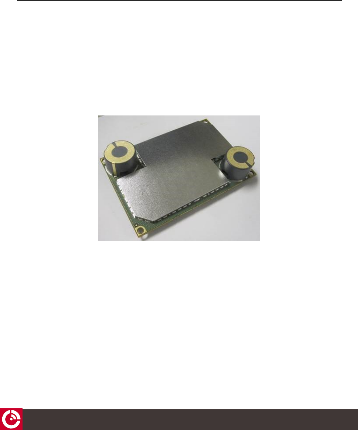
Figure 1: ST 6000
The ST 6000 is suitable for both industrial and fixed applications, and it can work as a standalone data-messaging
device, with built-in I/O data collection and processing capabilities. Feature-rich software tools make programming
easy and shorten the design and testing time.
1.1 Key Features and Benefits
The ST 6000 has the following key features and benefits:
lDesigned to be incorporated into a custom solution
lBuilt-in GNSS receiver to calculate position, speed, and heading that uses the satellite antenna
lBroad operational temperature range
lIsatData Pro message payload and latency capabilities
T407, VERSION 0.10 BETA
9
© ORBCOMM PROPRIETARY

ST 6000 - HARDWARE GUIDE
2 COMPLIANCE
Certification is pending for all the items below.
CE Mark Norms
lEN 301 426
lEN 301 489-20; EN 301 489-1
lEN 60950
lIEC 62311
FCC Regulations
lFCC ID: XGS-ST6000
l47 CFR 25
l47 CFR 15
lOET 65
Industry Canada Regulations
lIC ID: 11881A-ST6000
lICES-003
lRSS-170
lRSS-102
T407, VERSION 0.10 BETA
10
© ORBCOMM PROPRIETARY
Note: Integrators who integrate ST6000 OEM module into their final products should follow FCC and IC labeling rules
to indicate the final product "CONTAINS FCC ID: XGS-ST6000 and IC ID: 1181A-ST6000" on product label. In some
cases, If the regulation is applied, Integrators may need to get their own FCC ID and IC ID for the final product.
Anatel
Anatel certification and test results are available to Solution Providers for use as a baseline for the certification
approval of their ST 6000 enclosure.
In all cases, the SP is responsible for ensuring that their final ST 6000 enclosure complies with all local regulatory,
electrical and safety codes. As the ST 6000 enclosure contains the SP's power supply and possibly other circuitry that
affects the ST 6000, likely additional testing or a repeat of some of the tests listed below may be required.
Inmarsat Type Approval

ST 6000 - HARDWARE GUIDE
RoHS 2
lRestriction of Hazardous Substances (RoHS) 2 1
1European Union's (EU) Directive 2011/65/EU "Restriction of Hazardous Substances" (RoHS) 2 in Electronic and Electrical
Equipment.
T407, VERSION 0.10 BETA
11
© ORBCOMM PROPRIETARY
ST 6000 - HARDWARE GUIDE
3 SPECIFICATIONS
3.1 Connectors
3.1.1 ST 6000 Connector Details
See Table 1 for ST 6000 connector details.
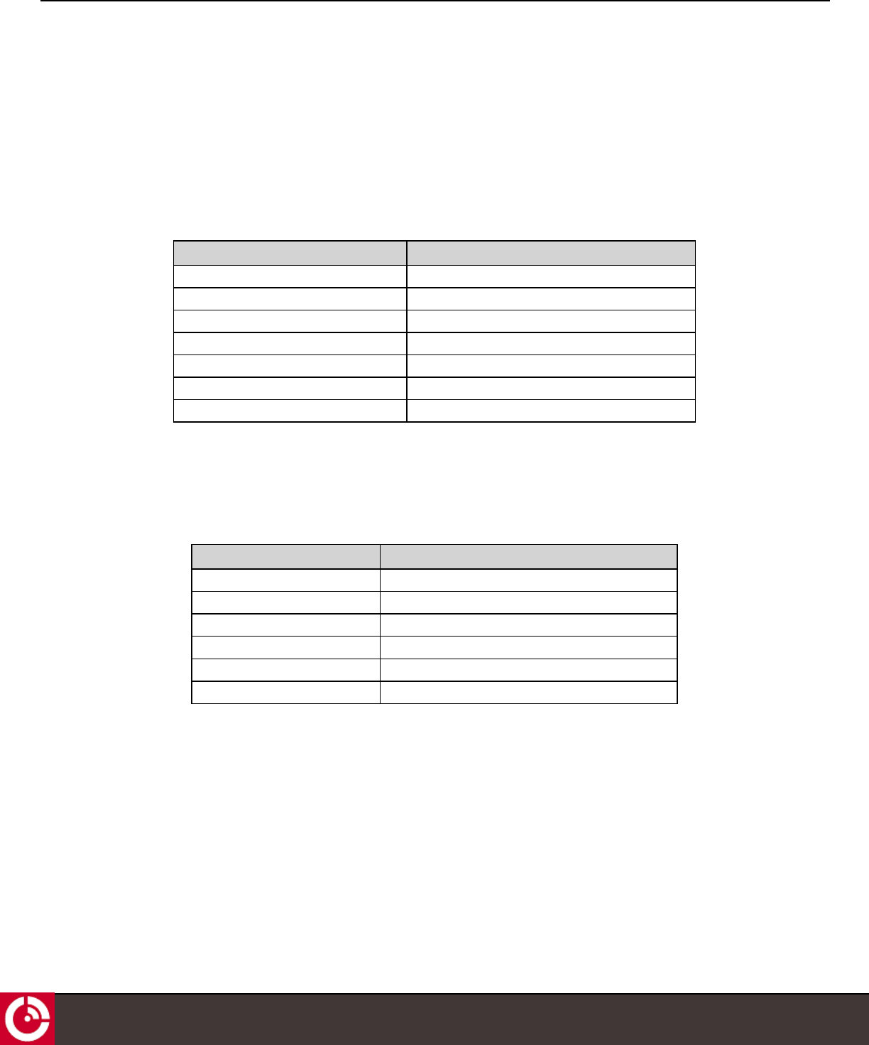
Table 1: Connector Details
Parameter
Manufacturer Part Number Samtec SFC-110-T2-L-D-A-K-TR
Connector Rectangular, shrouded female socket, SMT
Temperature Rating -55°C to +125°C
Insulator Material Black Liquid Crystal Polymer
Contact Material Phosphor Bronze
Configuration 2 x 10, SMT connector
Contact Rating 3.1 A per pin
3.1.2 Mating Connector Details
The ST 6000 requires a mating connector (not included), see Table 2.
Table 2: Mating Connector Details
Parameter
Manufacturer Part Number Samtec TFC-110-32-L-D
Connector Rectangular, shrouded male header, SMT
Temperature Rating -55°C to +125°C
Insulator Material Black Liquid Crystal Polymer
Device Material Phosphor Bronze
Contact Rating 3.1 A per pin
T407, VERSION 0.10 BETA
12
© ORBCOMM PROPRIETARY
ST 6000 - HARDWARE GUIDE
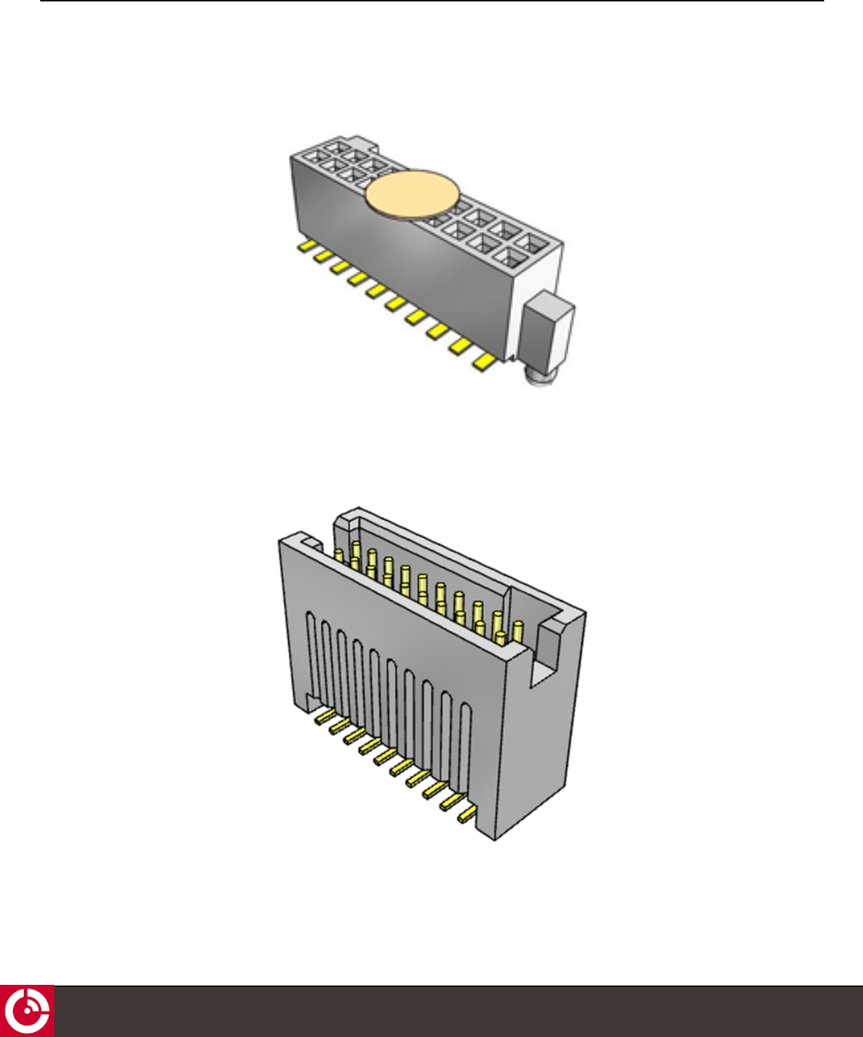
3.1.3 ST 6000 Connector
Figure 2: ST 6000 Connector
3.1.4 Mating Connector
Figure 3: Mating Connector
T407, VERSION 0.10 BETA
13
© ORBCOMM PROPRIETARY

ST 6000 - HARDWARE GUIDE
3.1.5 Connector Electrical Pin Assignment
Table 3: Electrical Pin Assignment (ST 6000)
PIN Functionality Description
1 GND The negative terminal of the external power supply must be connected to this pin.
2 VIN This pin is used to provide input power directly to the power amplifier circuitry. Regulated
power must be applied to this pin whenever the device drives the TX_PWR EN line high and
may be removed when the TX_PWR EN line is low. Alternatively, power may be applied to this
pin continuously.
3 VAUX This is the input power pin for the RF and baseband processors. Regulated power must be
applied to this pin continuously to keep the device alive.
4 TX PWR EN This is the control signal to apply power to the VIN pin. Power must be applied to VIN
whenever this signal is high. If not used (VIN powered continuously), this pin should be left
unconnected.
5 RS-485/J1708 TX 3.3 V transmit data connection to the external RS-485 transceiver. This signal can also be
connected to a J1708 network when the external transceiver is configured for J1708 operation.
6 AUX TX This pin is 3.3 V compatible TTL signal to be connected to the receive input of the external
serial port. May be used for logging and debugging.
7 RS-485/J1708 RX 3.3 V receive data connection from the external RS-485 transceiver. This signal can also be
connected to a J1708 network when the external transceiver is configured for J1708 operation.
8 AUX RX This pin is 3.3 V compatible TTL signal to be connected to the transmit output of the external
serial port. May be used for logging and debugging.
9 Console TX 3.3V compatible TTL transmit output from the modem console port to be connected to the
receive input of the external serial port.
10 OUT1 This pin is a 3.3 V TTL compatible connection for Output channel 5.
11 Console RX This pin is 3.3 V compatible TTL receive input to the modem console port to be connected to
the transmit output of the external serial port.
12 OUT2 This pin is a 3.3 V TTL compatible connection for Output channel 6.
13 I/O_1 This pin is 3.3V TTL compatible connection for Input / Output channel 1
14 I/O_3 This pin is 3.3V TTL compatible connection for Input / Output channel 3
15 I/O_2 This pin is 3.3V TTL compatible connection for Input / Output channel 2
16 I/O_4 This pin is 3.3V TTL compatible connection for Input / Output channel 4
17 1 PPS This pin is 3.3V TTL compatible 1 pulse per second output generated by the internal GNSS
module.
18 Console Valid This pin is 3.3V TTL compatible active high input that indicates if valid RS-232 levels are
present on the external console receiver input.
19 AUX Valid This pin is 3.3V TTL compatible active high input that indicates if valid RS-232 levels are
present on the external auxiliary receiver input.
20 Reset Out~ N/A
T407, VERSION 0.10 BETA
14
© ORBCOMM PROPRIETARY
ST 6000 - HARDWARE GUIDE
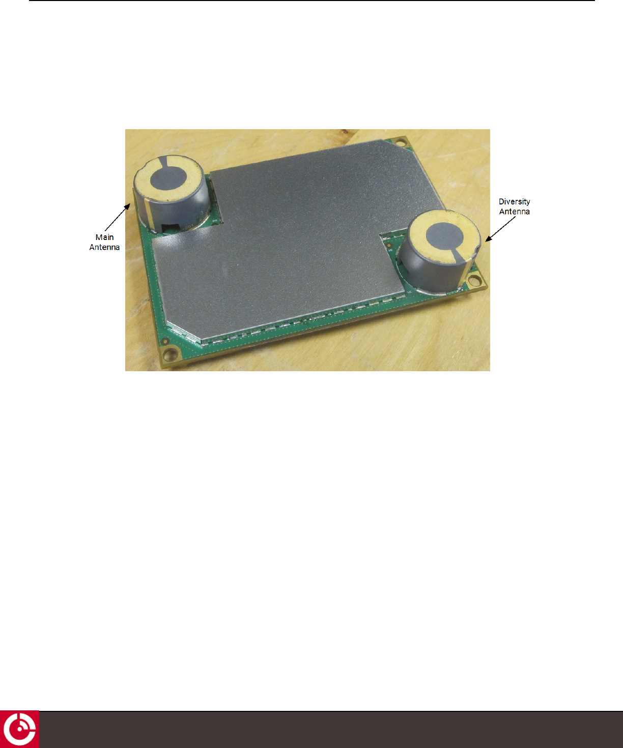
3.2 Antenna
The ST 6000 supports two standard onboard antennas: Main and Diversity. Refer to [T406] for general antenna
specifications.
Figure 4: Onboard Antennas
3.3 Power
3.3.1 Input Power
The ST 6000 has two power input pins (VAUX and VIN), and can be powered from either a single or dual external DC
power source.
VAUX supplies power to the ST 6000 baseband and RF processors. Regulated power must be applied to this pin
continuously to keep the device alive and synchronized with the satellite network.
VIN is the input power pin for the RF power amplifier circuitry. Regulated power must be applied to this pin whenever
the device drives the TX_PWR EN line high and may be removed when the TX_PWR EN line is low. Alternatively, power
may be applied to this pin continuously and TX_PWR_EN ignored.
Note: Input power protection is not provided on the ST 6000.
T407, VERSION 0.10 BETA
15
© ORBCOMM PROPRIETARY
ST 6000 - HARDWARE GUIDE
Table 4: Input Power
Parameter Values
VAUX voltage 3.5 to 5.8 VDC (6 V Max)
VAUX Ripple 50 mV p-p (max)
VAUX Current 600 mA (max)
VIN Voltage 5.8 VDC ± 3%
VIN Ripple 50 mV p-p (max)
VIN Current 1.6 A (max)
TX_PWR EN Asserted to VIN Stable 10 ms (max)
Reverse Polarity Protection None
Over Voltage Protection None
Over Current Protection None
ESD Protection Protection to ±30 kV contact discharge on all signals connected to the 20 pin
interface header, except for the power pins.
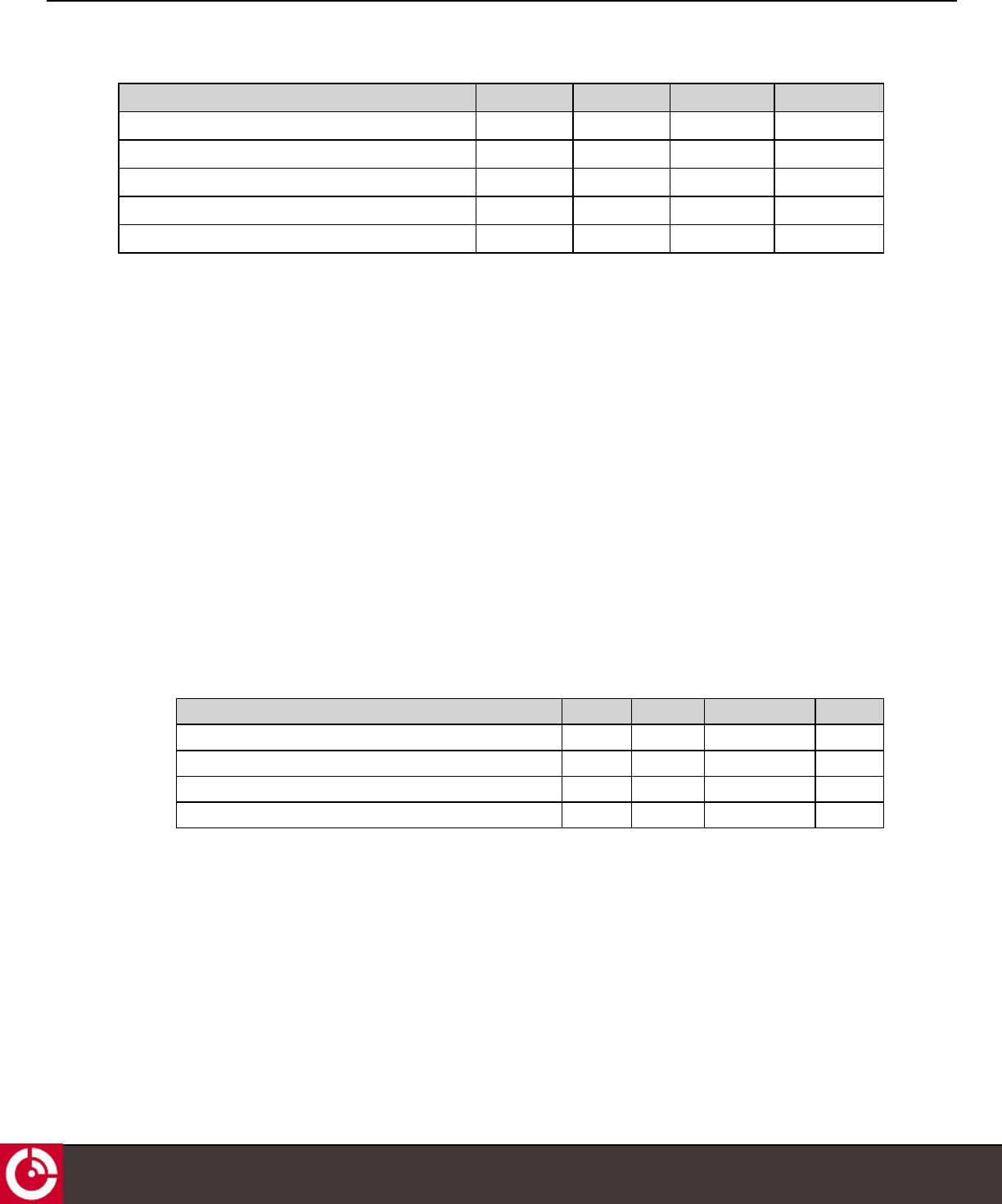
3.3.2 Power Consumption
Typical power consumption values at VIN and VAUX=5.8 V and at room temperature (23°C)
Table 5: ST 6000 Power Consumption
Scenario -40°C RT +85°C
VIN VAUX VIN VAUX VIN VAUX
Shutdown 10 nA 7.93 µA 10 nA 11 µA 10 nA 32.1 µA
Sleep 10 nA 108 µA 10 nA 129 µA 10 nA 211 µA
Power On 18.2 µA 23 mA 20.2 µA 24 mA 22.4 µA 26 mA
RFIC On 18.2 µA 37 mA 19.5 µA 38 mA 22.1 µA 40 ma
RFIC + GPS On 18.2 µA 84 mA 19.3 µA 83 mA 21.9 µA 84 mA
Tx On 0.83 A 275 mA 0.85 A 273 mA 0.81 A 274 mA
3.3.3 Inrush Current
Inrush current transients occur when the ST 6000:
lFirst powers on
lWakes up
lApplies power to the RF transmit circuitry
These transients are of very short duration and low energy but can have high peak currents. The power supply must
be capable of handling these inrush currents without dipping below the minimum input voltage of the respective
power rails. Typical inrush currents are listed in the following table.
T407, VERSION 0.10 BETA
16
© ORBCOMM PROPRIETARY
ST 6000 - HARDWARE GUIDE
Table 6: Inrush Current
Scenario1-40°C RT +85°C
VIN VAUX VIN VAUX VIN VAUX
Power Application - 1.71 A
(<343µs)
- 1.9 A
(<263µs)
- 1.6 A (<263µs)
RFIC On - 1.4 A (<333µs) - 2 A (<243µs) - 1.7 A (<253µs)
GPS On - 1 A (<243µs) - 1 A (<173µs) - 1 A (<212µs)
Tx Activation (with main
antenna)
1.5 A
(<1ms)
0.7 A (<262µs) 1.7 A
(<1ms)
0.6 A
(<105µs)
0.85 A
(<1ms)
0.35 A
(<425µs)
3.4 Input/Output
The ST 6000 I/Os are each independently operable and configurable in one of the following modes:
lAnalog input
lDigital input
lDigital output – push pull
The ST 6000 is equipped with various I/O ports. Refer to the pin number descriptions in section 3.1.5 for an
explanation of each I/O signal. To connect these ports to an external device you may need to use a suitable translator
depending on what the signal is connected to.
The I/O electrical characteristics of this interface are shown in Table 7 and Table 8 shows the analog characteristics.
Table 7: I/O Electrical Characteristics
Parameter Min. Typ. Max. Units
Input high voltage threshold 2.31 - - V
Input low voltage threshold - - 1.155 V
Output high voltage threshold 2.8 - - V
Output low voltage threshold - - 0.5 V
Output high voltage, high drive strength - - -8 mA
Output high voltage, low drive strength - - -2 mA
Output low voltage, high drive strength - - 9 mA
Output low voltage, low drive strength - - 2 mA
OUT1 and OUT2 are dedicated push-pull outputs only. These outputs may be used to drive off board circuitry capable
of driving high current loads.
1All VIN and VAUX measurements were performed at 5.8 V.
T407, VERSION 0.10 BETA
17
© ORBCOMM PROPRIETARY
ST 6000 - HARDWARE GUIDE
Table 8: Analog Input Characteristics
Parameter Min. Typ. Max. Units
Input resistance - 2 5 kΩ
Input capacitance - 4 5 pF
Normal input range 0 - 3.3 V
Resolution (12 bits) - 0.8 - mV
Full scale error - - 5.4 LSB
3.4.1 Input Bandwidth
When used as a digital or analog input, the bandwidth of the I/O circuitry is 1 kHz or more.
Note: This does not imply that the software must have a sample rate greater than 1 Hz.
3.4.2 Output Bandwidth
When used as a digital output the I/O circuitry has a bandwidth exceeding 100Hz.
Note: This does not imply that the software must have the capability of generating high rate pulse trains at
frequencies > 10 Hz.
3.5 Serial Interfaces
The ST 6000 is equipped with various serial ports. To connect these ports to a standard RS-232 serial device such as
a computer for example, you must use a 3.3 V TTL/CMOS to RS-232 translator device.
The electrical characteristics (Table 9) of the interface are:
Table 9: Electrical Characteristics
Parameter Min. Typical Max. Units
Rx input high voltage threshold 2.31 V
Rx input low voltage threshold 1.155 V
Tx output high voltage threshold 2.8 V
Tx output low voltage threshold - 0.5 V
3.5.1 Console/Auxiliary (RS-232) Interface
The ST 6000 is equipped with an RS-232 console and an auxiliary TTL level serial port. The auxiliary port is primarily
intended for debug output or software upgrade downloads. The console and auxiliary serial port is connected directly
to the UART of the microcontroller and therefore communicates via CMOS level RS-232 style signaling (0-3.3 V, non-
inverted).
The console and auxiliary serial interfaces to the ST 6000 are asynchronous with 1 start bit, 8 data bits, no parity, 1
stop bit; the default rate is 9600 bps, while the maximum rate is 115.2 kbps. The interfaces are 3.3 V TTL compatible.
T407, VERSION 0.10 BETA
18
© ORBCOMM PROPRIETARY
ST 6000 - HARDWARE GUIDE
3.5.2 RS-485/J1708 Interface
The ST 6000 has a dedicated TTL level serial port for interfacing to an RS-485/J1708 interface as an accessory bus
and for SCADA interfacing. The ST 6000 does not incorporate a driver and termination resistor. The RS-485 serial port
is connected directly to the UART of the microcontroller and therefore communicates via 3.3 V CMOS levels.
3.6 Accelerometer/GNSS/Temperature Sensor
The ST 6000 supports an accelerometer, a multi-GNSS module, and a temperature sensor. Refer to [T406] for details.
3.7 RF Specifications
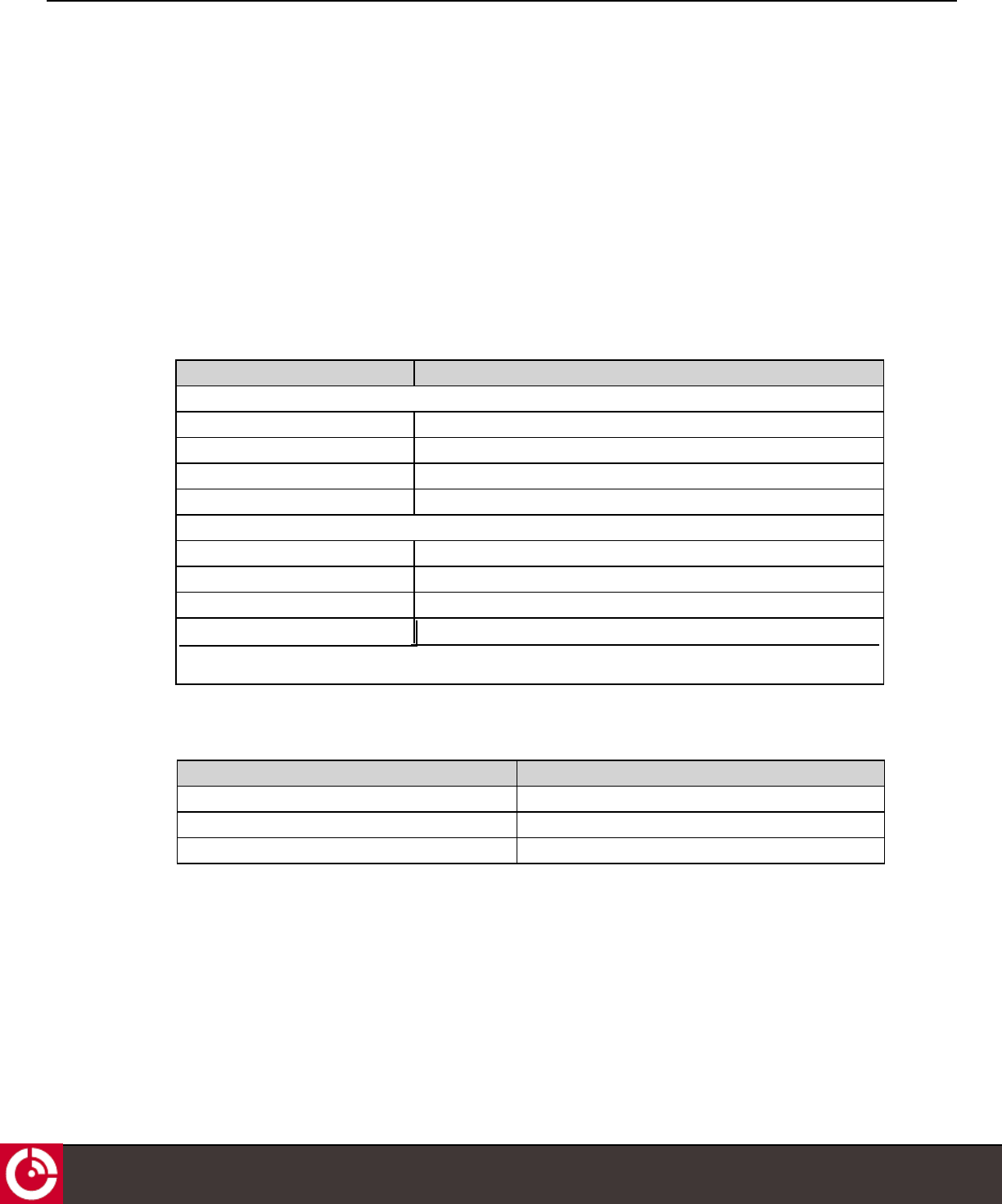
3.7.1 Frequency
Parameter Value
Receive
Frequency Band 1525 to 1559 MHz
Modulation OQPSK
Symbol Rate 3000 symbols/seconds
Polarization RHCP
Transmit
Frequency Band 1626.5 to 1660.5 MHz
Modulation OQPSK
Symbol Rate 900 symbols/seconds (maximum)
Polarization RHCP
Parameter Value
Maximum EIRP 7 dBW
Elevation Angle 0 to 90 degrees
Maximum transmit antenna gain 3.9 dBic
3.8 GNSS
The manufacturer's specifications are given in the table below.
T407, VERSION 0.10 BETA
19
© ORBCOMM PROPRIETARY
Typical Output Power 1.5W
WARNING: Please keep the device minimum 20cm away from human body
3.7.2 Antenna
ST 6000 - HARDWARE GUIDE
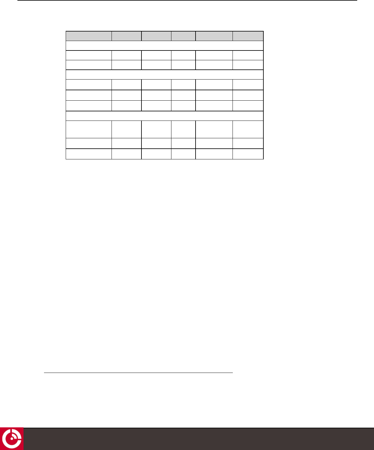
Table 10: Multi-GNSS Specifications
Parameter GPS GLONASS BeiDou GPS/GLONASS GPS/BeiDou
Time to First Fix1
Cold Start 29 s 30 s 36 s 26 s 27 s
Hot Start 1 s 1 s 1 s 1 s 1 s
Sensitivity
Tracking -166 dBm -166 dBm -160 dBm -167 dBm -165 dBm
Hot Start -156 dBm -155 dBm -155 dBm -156 dBm -156 dBm
Cold Start -148 dBm -145 dBm -138 dBm -148 dBm -148 dBm
Accuracy
Horizontal Position
(CEP) 2
2.5/2.0 m 4.0 m 3.0 m 2.5/2.0 m 2.5/2.0 m
Velocity 0.05 m/s 0.1 m/s 0.1 m/s 0.05 m/s 0.05 m/s
Heading 0.3 degrees 0.4 degrees - 0.3 degrees 0.3 degrees
3.9 Accelerometer
The device has an internal 3D accelerometer to detect motion in any axis. Figure 5 shows the positive axes for the
accelerometer.
1All satellites at -130 dBm
2CEP, 50%, 24 hours static, -130 dBm
T407, VERSION 0.10 BETA
20
© ORBCOMM PROPRIETARY
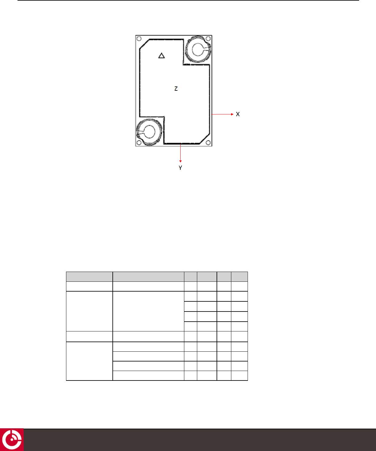
ST 6000 - HARDWARE GUIDE
Figure 5: Accelerometer Axis
The accelerometer is very important for low power devices when it is critical to save power while stationary and
quickly detect when motion starts. In powered devices where low power is not critical, GPS can be polled to detect
motion. However, for low power applications frequent GPS fixes can dominate the power budget. To reduce power
budget effects of GPS fixes, an accelerometer can be used to trigger a GPS fix to detect if motion occurred.
The accelerometer thresholds to detect motion vary depending on the environment. In order to avoid, false motion
detects, extensive testing is required to ensure that adequate acceleration magnitude thresholds and time durations
are used. Refer to [T405] for further details about the accelerometer.
Table 11: Accelerometer Specifications
Parameter Condition Min. Typical Max. Units
Resolution 2 g - 3.91 - mG
Tracking software selectable - ±2 - g
- ±4 - g
- ±8 - g
- ±16 - g
Bandwidth Filtering Selectable via digital interface 8 - 1000 Hz
Sensitivity 2 g - 256 - LSB/g
4 g - 128 - LSB/g
8 g - 64 - LSB/g
16 g - 32 - LSB/g
T407, VERSION 0.10 BETA
21
© ORBCOMM PROPRIETARY
ST 6000 - HARDWARE GUIDE
If using the accelerometer, mount the device in one of the configurations shown in [T405].
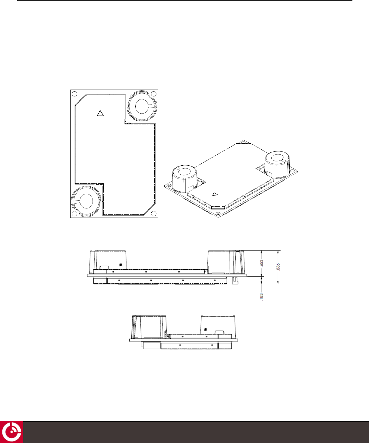
3.10 Mechanical
3.10.1 Dimensions
Figure 6: ST 6000 Top View
Figure 7: ST 6000 Side View Dimensions (in.)
T407, VERSION 0.10 BETA
22
© ORBCOMM PROPRIETARY
ST 6000 - HARDWARE GUIDE
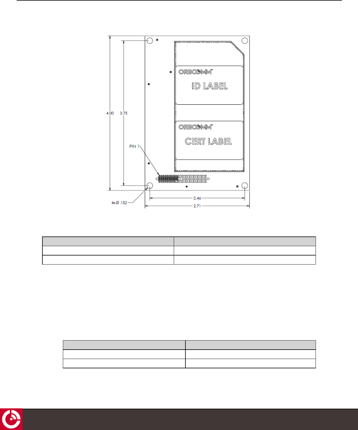
Figure 8: ST 6000 Bottom View Dimensions (in.)
3.10.2 Mass and UV Resistance
Parameter Value
ST 6000 mass 59.4 g
UV resistance TBD
3.11 LED
The ST 6000 has a white visual indicator that is controlled by the software. It is a power indicator during initial power
on, otherwise it is off.
3.12 Nonvolatile Storage
The device has nonvolatile flash memory, which is shared by both the device firmware and user services.
Parameter Value
Nonvolatile Onboard Flash Storage 4 MB
Write-Erase Cycles (per operating life) 100 000
T407, VERSION 0.10 BETA
23
© ORBCOMM PROPRIETARY
ST 6000 - HARDWARE GUIDE
3.13 Environmental
3.13.1 Temperature
Parameter Value
Operating Temperature -40° to +85°C
Storage Temperature -40° to +85°C
3.13.2 Environmental
Parameter Description
Vibration The ST 6000 meets all its specifications during exposure to random vehicular vibration levels per
SAE J1455, section 4.9.4.2 figures 6, 7, and 8, and MIL-STD-810G, section 514.6, figure 514.6C-1.
Mechanical Shock The ST 6000 meets all its specifications after exposure to positive and negative saw tooth shock
pulses with peaks of 20G and durations of 11 ms as specified in MIL-STD-810G, section 516.6,
Procedure I, section 2.3.2c.
Altitude The ST 6000 meets all of its specifications after a non-operating 12.2 km altitude test as detailed in
SAE J1455, section 4.9.3, except with an ambient temperature of -40 °C.
Thermal Shock The ST 6000 meets all of its specifications after a thermal shock test as detailed in SAE J1455,
section 4.1.3.2.
ESD The ST 6000 meets all its specifications after exposure of the ST 6000 to 2 kV ESD contact
discharge per IEC 60945 and IEC 61000-4-2, level 3.
All the connections on the connectors, except for the VIN and VAUX power rails, are ESD protected
to ±30 kV contact discharge according to IEC 61000-4-2 far exceeding level 4.
T407, VERSION 0.10 BETA
24
© ORBCOMM PROPRIETARY

ST 6000 - HARDWARE GUIDE
4 INTEGRATION GUIDELINES
This section contains a number of guidelines to assist the Solution Provider (SP) in building their ST 6000 enclosure.
It must be recognized that this section provides guidelines only and each SP must use their own discretion to finalize
the integration approach that works for them.
4.1 Enclosure Design
The ST 6000 is not designed for outdoor environments. Consequently, the ST 6000 requires a robust
environmentally sealed enclosure that can house the ST 6000.
The following guidelines are recommended for the enclosure design.
lAn IP67 rating or better for outdoor use.
lUse enclosure materials that are transparent to L-Band (1-2 GHz) radio signals.
lTwo recommended enclosure materials are:
lXenoy®Resin 5220U. This plastic material offers good chemical and UV resistance and great impact
resistance even at low temperatures.
lLexan EXL 9330.
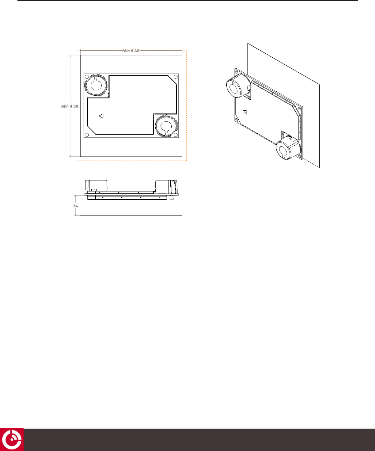
4.2 Ground Plane Requirements
A metal plate is required under the antenna board. The optimal recommended separation between the metal plate
and the modem card is 0.86”. This can be reduced to 0.5” with some moderate impact on low elevation gain.
If the ST 6000 is installed on a metal surface larger than the metal plate size indicated in Figure 9, then no metal plate
is needed as long as the surface-to-antenna distance is the same as shown in Figure 9.
T407, VERSION 0.10 BETA
25
© ORBCOMM PROPRIETARY
ST 6000 - HARDWARE GUIDE
Figure 9: Ground Plane Requirements (in.)
4.3 Labeling
The mobile ID on the ST 6000 is the network identification number. It is recommended that the SP place a copy of
the mobile ID on the exterior of the enclosure housing the device. With the mobile ID on the enclosure, installers can
readily identify the network identification number.
T407, VERSION 0.10 BETA
26
© ORBCOMM PROPRIETARY